EP3449185B1 - Turbomaschineneinspritzsystem mit einem aerodynamischen deflektor an seinem einlass und einem lufteinlassverwirbler - Google Patents
Turbomaschineneinspritzsystem mit einem aerodynamischen deflektor an seinem einlass und einem lufteinlassverwirbler Download PDFInfo
- Publication number
- EP3449185B1 EP3449185B1 EP17725689.8A EP17725689A EP3449185B1 EP 3449185 B1 EP3449185 B1 EP 3449185B1 EP 17725689 A EP17725689 A EP 17725689A EP 3449185 B1 EP3449185 B1 EP 3449185B1
- Authority
- EP
- European Patent Office
- Prior art keywords
- air intake
- injection system
- axis
- swirler
- aerodynamic deflector
- Prior art date
- Legal status (The legal status is an assumption and is not a legal conclusion. Google has not performed a legal analysis and makes no representation as to the accuracy of the status listed.)
- Active
Links
- 238000002347 injection Methods 0.000 title claims description 69
- 239000007924 injection Substances 0.000 title claims description 69
- 238000011144 upstream manufacturing Methods 0.000 claims description 31
- 238000002485 combustion reaction Methods 0.000 claims description 22
- 239000000446 fuel Substances 0.000 claims description 14
- 239000000203 mixture Substances 0.000 claims description 7
- 238000002156 mixing Methods 0.000 description 2
- 230000001681 protective effect Effects 0.000 description 2
- 239000000654 additive Substances 0.000 description 1
- 230000000996 additive effect Effects 0.000 description 1
- 238000000889 atomisation Methods 0.000 description 1
- 230000000295 complement effect Effects 0.000 description 1
- 230000001788 irregular Effects 0.000 description 1
- 239000007788 liquid Substances 0.000 description 1
- 238000004519 manufacturing process Methods 0.000 description 1
- 238000002844 melting Methods 0.000 description 1
- 230000008018 melting Effects 0.000 description 1
- 238000009834 vaporization Methods 0.000 description 1
- 230000008016 vaporization Effects 0.000 description 1
Images


Classifications
-
- F—MECHANICAL ENGINEERING; LIGHTING; HEATING; WEAPONS; BLASTING
- F23—COMBUSTION APPARATUS; COMBUSTION PROCESSES
- F23R—GENERATING COMBUSTION PRODUCTS OF HIGH PRESSURE OR HIGH VELOCITY, e.g. GAS-TURBINE COMBUSTION CHAMBERS
- F23R3/00—Continuous combustion chambers using liquid or gaseous fuel
- F23R3/02—Continuous combustion chambers using liquid or gaseous fuel characterised by the air-flow or gas-flow configuration
- F23R3/04—Air inlet arrangements
- F23R3/10—Air inlet arrangements for primary air
- F23R3/12—Air inlet arrangements for primary air inducing a vortex
- F23R3/14—Air inlet arrangements for primary air inducing a vortex by using swirl vanes
-
- F—MECHANICAL ENGINEERING; LIGHTING; HEATING; WEAPONS; BLASTING
- F23—COMBUSTION APPARATUS; COMBUSTION PROCESSES
- F23R—GENERATING COMBUSTION PRODUCTS OF HIGH PRESSURE OR HIGH VELOCITY, e.g. GAS-TURBINE COMBUSTION CHAMBERS
- F23R3/00—Continuous combustion chambers using liquid or gaseous fuel
- F23R3/02—Continuous combustion chambers using liquid or gaseous fuel characterised by the air-flow or gas-flow configuration
- F23R3/26—Controlling the air flow
-
- F—MECHANICAL ENGINEERING; LIGHTING; HEATING; WEAPONS; BLASTING
- F23—COMBUSTION APPARATUS; COMBUSTION PROCESSES
- F23R—GENERATING COMBUSTION PRODUCTS OF HIGH PRESSURE OR HIGH VELOCITY, e.g. GAS-TURBINE COMBUSTION CHAMBERS
- F23R3/00—Continuous combustion chambers using liquid or gaseous fuel
- F23R3/28—Continuous combustion chambers using liquid or gaseous fuel characterised by the fuel supply
- F23R3/286—Continuous combustion chambers using liquid or gaseous fuel characterised by the fuel supply having fuel-air premixing devices
Definitions
- the present invention relates to an air intake swirler intended to form part of an air and fuel injection system in a turbomachine, as well as an injection system for a turbomachine comprising at least one such swirler. air intake, and a turbomachine for an aircraft comprising such an injection system.
- the document WO 2010/081940 A1 discloses an injection system for injecting a mixture of air and fuel into a combustion chamber of a turbomachine according to the preamble of claim 1.
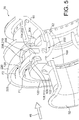
- the figure 1 attached illustrates a turbomachine 10 for an aircraft of a known type, for example a bypass turbojet, generally comprising a fan 12 intended for the suction of an air flow dividing downstream of the fan into a flow primary supplying a core of the turbomachine and a secondary flow bypassing this core.
- the heart of the turbomachine generally comprises a low pressure compressor 14, a high pressure compressor 16, a combustion chamber 18, a high pressure turbine 20 and a low pressure turbine 22.
- the turbomachine is streamlined by a nacelle 24 surrounding the flow space 26 of the secondary flow.
- the rotors of the turbomachine are mounted to rotate about a longitudinal axis 28 of the turbomachine.
- the figure 2 represents the combustion chamber 18 of the turbomachine of the figure 1 .
- this combustion chamber which is of the annular type, comprises two coaxial annular walls, respectively radially internal 32 and radially external 34, which extend from upstream to downstream, in the direction 36 of flow. the primary flow of gas in the turbomachine, around the axis of the combustion chamber which merges with the axis 28 of the turbomachine.
- These internal 32 and external 34 annular walls are interconnected at their upstream end by an annular chamber bottom wall 40 which extends substantially radially around the axis 28.
- This annular chamber bottom wall 40 is equipped with injection systems 42 distributed around the axis 28 to allow, each, the injection of a pre-mixture of air and fuel centered along a respective injection axis 44.
- injection systems 42 distributed around the axis 28 to allow, each, the injection of a pre-mixture of air and fuel centered along a respective injection axis 44.
- the axial and radial directions are defined with reference to the injection axis 44.
- a transverse plane is a plane orthogonal to the injection axis 44.
- the combustion chamber generally comprises an annular protective shroud 45 extending opposite an upstream face of the chamber bottom wall 40 and comprising orifices for passage of injectors and for air intake.
- a part 46 of an air flow 48 coming from a diffuser 49 and coming from the compressor 16 feeds the injection systems 42 while another part 50 of this air flow bypasses the combustion chamber. by flowing downstream along the coaxial walls 32 and 34 of this chamber and in particular allows the supply of air inlet openings provided within these walls 32 and 34.
- each injection system 42 generally comprises a sleeve 52, sometimes referred to as a “sliding bushing”, in which a fuel injection nose 54 forming the end of an injector arm 55 is mounted, as well as one or more air intake swirls 56, 58, and finally a bowl 60, sometimes referred to as a “mixing bowl” or “pre-vaporization bowl”, which essentially takes the form of an annular wall having a flared tapered portion downstream.
- a sleeve 52 sometimes referred to as a “sliding bushing”
- a fuel injection nose 54 forming the end of an injector arm 55
- one or more air intake swirls 56, 58 and finally a bowl 60, sometimes referred to as a “mixing bowl” or “pre-vaporization bowl”, which essentially takes the form of an annular wall having a flared tapered portion downstream.
- the air intake tendrils 56, 58 are separated from each other by an annular wall which extends radially inwards to form a annular internal deflection wall 62, also called “venturi”, having an internal profile of convergent-divergent shape.
- the injection systems 42 have an essential role in the operation of the combustion chamber. Their efficiency depends in particular on the quality of their air supply which comes directly from the diffuser.
- the air intake augers 56, 58 contribute to the mixing of air and fuel.
- Each spinner 56, 58 thus comprises an annular row of inclined fins so as to set the air flow 64 in rotation and thus improve the atomization of the fuel jet coming from the fuel injection nose 54.
- some of this fuel trickles in liquid form on the internal surface of the venturi 62 and is sheared by the swirling air at the downstream end of the venturi 62.
- the object of the invention is to improve the performance of the injection systems of turbomachines.
- an injection system for injecting a mixture of air and fuel into a combustion chamber of a turbomachine with an air intake swirl comprising an upstream wall and a downstream wall both of revolution around 'an axis of the air intake swirler, and fins distributed around the axis and connecting the upstream wall to the downstream wall so as to delimit between the upstream and downstream walls air inlet channels having each has an inlet arranged on a radially outer side and an outlet arranged on a radially inner side.
- the air intake swirler further comprises an aerodynamic deflector which extends the downstream wall radially outwards to a free end of the aerodynamic deflector, and which has a concavity facing upstream of so that the aerodynamic deflector extends radially opposite the respective inlets of the air inlet channels.
- the aerodynamic deflector makes it possible to channel the air flow intended to enter the air inlet channels and therefore to limit the pressure losses of this air flow as much as possible.
- the aerodynamic deflector extends continuously over 360 degrees around the axis, from the downstream wall to the free end of the aerodynamic deflector.
- the aerodynamic deflector comprises recesses formed in the free end of the aerodynamic deflector so as to define between them teeth respectively arranged opposite the respective inlets of the air inlet channels. .
- the upstream and downstream walls extend substantially orthogonally to the axis.
- the aerodynamic deflector is preferably shaped so that at each point of the free end of the aerodynamic deflector, a circumferential plane tangent to a radially inner edge of the free end is substantially parallel to the axis of the twist air intake.
- the injection system for injecting a mixture of air and fuel into a combustion chamber of a turbomachine also comprises a sleeve for centering an injector, a bowl, and at least a first spinner. Air intake of the type described above arranged axially between the sleeve and the bowl.
- the injection system further comprises a second air intake swirler also of the type described above, arranged axially between the first air intake swirler and the bowl.
- downstream wall of the first air intake swirler is the upstream wall of the second air intake swirler.
- the injection system advantageously comprises an annular internal deflection wall having an internal profile of converging-diverging shape, which extends the downstream wall of the first air intake swirl towards the interior of the injection system.
- the respective free ends of the respective aerodynamic deflectors of the first and second air intake swirlers extend substantially in the same transverse plane.
- the upstream wall of the first air intake swirler advantageously extends in the same transverse plane.
- the respective free ends of the respective aerodynamic deflectors of the first and second air intake swirlers can be offset with respect to each other in the direction of the axis of the air intake swirler.
- At least one of the respective aerodynamic deflectors of the first and second air intake swirlers is shaped so that the radial extent of the air intake section of the intake swirler d The corresponding air varies around the axis of the air intake swirl.
- the invention also relates to a turbomachine for an aircraft, comprising a combustion chamber and at least one injection system of the type described above for supplying the combustion chamber with a mixture of air and fuel.
- the figures 4 and 5 illustrate an injection system 70 similar to the injection system 42 of the figure 2 described above but comprising two air intake swirls 100, 200.
- the injection system 70 is intended to equip an aircraft turbomachine of the same type as the turbomachine of the figure 1 described above, or any other type of turbomachine.
- the injection system 70 thus comprises a bush 52 intended to receive a fuel injection nozzle, the air intake swirls 100, 200, and a bowl 60.
- the air intake swirls 100, 200 are intended for the injection of a swirling air flow into two internal annular spaces of the injection system separated from each other by an annular internal deflection wall 62 having an internal profile of convergent-divergent shape, also called “venturi”, as explained above in relation to the injection system 42 of known type.
- the first air intake swirl 100 also called an "internal swirl", comprises an upstream wall 102 and a downstream wall 104 which are both of revolution about an axis of the swirler which merges with the axis. injection 44 of the injection system.
- the first air intake swirl 100 further comprises fins 106 distributed around the axis 44 and connecting the upstream wall 102 to the downstream wall 104 so as to define between the upstream and downstream walls air inlet channels 108.
- Each air inlet channel 108 has an inlet 110 arranged on a radially outer side and an outlet 112 arranged on a radially inner side. More precisely, each inlet 110 is delimited between respective radially outer ends of two consecutive fins 106 which delimit the corresponding air inlet channel 108. Similarly, each outlet 112 is delimited between respective radially internal ends of two consecutive fins 106 which delimit the corresponding air inlet channel 108.
- the first air intake swirler 100 further comprises an aerodynamic deflector 120 which extends the downstream wall 104 radially outwards to a free end 122 of the aerodynamic deflector 120.
- the latter has a turned concavity. upstream.
- the aerodynamic deflector 120 thus extends radially opposite the respective inlets 110 of the air inlet channels 108.
- the free end 122 of the aerodynamic deflector 120 is therefore oriented generally in the upstream direction and delimits a section of air inlet of the first air inlet swirl 100.
- the aerodynamic deflector 120 thus makes it possible to channel the air flow F1 entering the air inlet channels 108 and therefore to limit the pressure losses of this air flow as much as possible.
- the aerodynamic deflector 120 extends continuously over 360 degrees around the axis 44, from the downstream wall 104 to the free end 122 of the aerodynamic deflector 120.
- the upstream 102 and downstream 104 walls of the first air intake swirler 100 extend orthogonally to the axis 44.
- the swirler is therefore of the radial type and thus has optimum compactness in the direction. axial.
- upstream 102 and downstream 104 walls can be inclined relative to the axis 44, without departing from the scope of the invention.
- the aerodynamic deflector 120 has a curved shape from the downstream wall 104 and up to the free end 122.
- the aerodynamic deflector 120 can advantageously be manufactured by means of an additive manufacturing process, for example of the selective laser melting (SLM) type.
- SLM selective laser melting
- the aerodynamic deflector 120 may have one or more curved axial sections and one or more cylindrical or frustoconical axial sections arranged axially end-to-end, without departing from the scope of the invention.
- the aerodynamic deflector 120 may consist of a succession of axial sections of frustoconical shape, having respective apex angles that are all the smaller as the axial section considered is away from the downstream wall 104.
- the aerodynamic deflector 120 can have a segmented curvature instead of a continuous curvature, without departing from the scope of the invention.
- the aerodynamic deflector 120 is shaped so that at each point of its free end 122, a circumferential plane P1 tangent to a radially inner edge 124 of the free end 122 is parallel to the axis 44 of the first air intake swirl 100.
- the air intake section of the first air intake swirl 100 is greater than or equal to three times the sum of the respective passage sections of the inlet channels d. air 108 from the first 100 air intake spin.
- At least one of the respective aerodynamic deflectors (120,220) of the first and second air intake swirls (100,200) is shaped so that the radial extent (S1, S2) of the inlet section d
- the air from the corresponding air intake swirl varies around the axis (44).
- the first aerodynamic deflector 120 may have an irregular shape around the axis 44 so as to adapt the radial extent S1 of the air inlet section to the pressure irregularities of the air flow 46 coming from the diffuser. 49 of the turbomachine, as will appear more clearly in what follows.
- the second air intake swirl 200 which is arranged axially between the first air intake swirl 100 and the bowl 60, has a configuration similar to that of the first air intake swirl 100.
- the second air intake swirl 200 also called an “external swirl”, comprises an upstream wall 202, which is the downstream wall 104 of the first air intake swirl 100, and a downstream wall 204
- the two walls 202, 204 are of revolution about the axis of the swirler 200 which merges with the injection axis 44 of the injection system.
- the second air intake swirler 200 further comprises fins 206 distributed around the axis 44 and connecting the upstream wall 202 to the downstream wall 204 so as to delimit between the upstream and downstream walls of the inlet channels d. air 208.
- Each air inlet channel 208 has an inlet 210 arranged on a radially outer side and an outlet 212 arranged on a radially inner side.
- each inlet 210 is delimited between respective radially outer ends of two consecutive fins 206 which delimit the corresponding air inlet channel 208.
- each outlet 212 is delimited between respective radially internal ends of two consecutive fins 206 which delimit the corresponding air inlet channel 208.
- the second air intake swirler 200 comprises an aerodynamic deflector 220 which extends the downstream wall 204 radially outward to a free end 222 of the aerodynamic deflector 220 oriented generally in the upstream direction and delimiting an air inlet section of the second air inlet swirl 200.
- the aerodynamic deflector 220 has characteristics similar to those of the aerodynamic deflector 120 of the first air intake swirl 100 described above, and thus makes it possible to channel the air flow F2 entering the inlet channels of air 208.
- a circumferential plane P2 tangent to a radially inner edge 224 of the free end 222 is parallel to the axis 44 of the second air intake swirl 200 ( figure 4 ).
- the respective free ends 122, 222 of the respective aerodynamic deflectors 120, 220 of the first and second air intake swirlers 100, 200 extend substantially in the same transverse plane P3, in which extends also the upstream wall 102 of the first air intake swirl 100.
- the air intake sections delimited respectively by the aerodynamic deflectors 120 and 220 are defined substantially in the transverse plane P3.
- annular internal deflection wall 62 extends in the extension of the downstream wall 104 of the first air intake swirl 100 towards the interior of the injection system 70.
- FIGS. 6 and 7 illustrate an injection system 70A generally similar to the injection system 70 described above, but in which the first and second air intake swirls 100A, 200A differ from the swirls 100, 200 described above, because that each of their respective aerodynamic deflectors 120A, 220A has recesses 126A, 226A formed in its free end 122A, 222A. These recesses 126A, 226A define between them teeth 128A, 228A respectively arranged facing the respective inlets 110, 210 of the air inlet channels 108, 208.
- the teeth 128A of the aerodynamic deflector 120A of the first air intake swirl 100A are advantageously offset angularly with respect to the teeth 228A of the aerodynamic deflector 220A of the second air intake swirl 200A, so that each tooth 128A or arranged axially facing a corresponding recess 226A.
- the recesses 126A of the aerodynamic deflector 120A of the first air intake swirl 100A thus allow additional air to pass in the direction of the second air intake swirl 200A.
- an injection system according to the invention may comprise a first air intake swirler in accordance with the second embodiment described above and a second air intake swirler in accordance with the first embodiment described. above, or vice versa.
- the figure 8 illustrates an injection system 70B generally similar to the injection system 70 described above, but in which the aerodynamic deflector 220B of the second air intake swirl 200B is shaped so that the radial extent S2 of the air inlet section of said air intake swirl 200B varies around the axis 44.
- the aerodynamic deflector 220B is in particular shaped so that its free end 222B is circular in shape and is eccentric with respect to the axis 44.
- the free end 222B is for example eccentric from the axis 44 in a direction oriented radially. outwards in relation to axis 28 of the combustion chamber (visible on the figure 2 ).
- the radial extent S2 preferably takes a minimum value S2min equal to half of a nominal value corresponding to the radial extent that an equivalent section but of constant radial extent would have (as in the figures 4 and 5 ).
- the radial extent S2 preferably takes a maximum value S2max equal to three times the nominal value.
- the variability of the radial extent S2 of the air inlet section can be obtained by a non-axisymmetric shape of the aerodynamic deflector 220B, for example an eccentric oval shape.
- the aerodynamic deflector of the first air intake swirler can adopt a configuration such that the radial extent S1 of the air inlet section of the first air intake swirler varies around axis 44.
- the variability of the radial extent of the air inlet section of at least one of the air inlet swirlers makes it possible to optimize the homogeneity of the air supply of the air inlet.
- this spin having regard to various design parameters of the turbomachine, including in particular the possible heterogeneity of the flow at the outlet of compressor 16, the wake induced by the injector arm 55 in the air flow supplying the system d injection 70B, and the influence of the protective annular fairing 45 on the aforementioned air flow.
- the figures 9 and 10 respectively illustrate injection systems 70C and 70D generally similar to the injection system 70 described above, but in which the respective free ends of the respective aerodynamic deflectors of the first and second air intake swirlers are offset one by one with respect to the other in the direction of axis 44.
- the aerodynamic deflector 120C of the first air intake swirl 100C extends upstream beyond the free end 222 of the aerodynamic deflector 220 of the second air intake swirl 200.
- the aerodynamic baffle 220D of the second air intake twist 200D extends upstream beyond the free end 122 of the aerodynamic baffle 120 of the first air intake twist 100.
- the figure 11 illustrates a 70E injection system similar to that of the figure 10 , except in that the aerodynamic deflector 220E of the second air intake swirl 200E has an oval or oblong free end 222E, extending for example from an annular portion of circular section 223E of the deflector.
- the major axis 230E of the free end 222E is oriented in a circumferential direction defined with respect to the axis 28 of the combustion chamber (visible on the figure 2 ).
- the shape of the free end 222E provides variability in the radial extent of the air inlet section of the second air inlet swirl 200E around axis 44, similarly to what has been described with reference to the figure 8 .
Claims (12)
- Einspritzsystem (70; 70A; 70B; 70C; 70D; 70E) zum Einspritzen eines Gemisches aus Luft und Kraftstoff in eine Brennkammer einer Turbomaschine, umfassend eine Hülse (52) zum Zentrieren eines Injektors, eine Schale (60), einen ersten Lufteinlassverwirbler (100; 100A; 100C), der axial zwischen der Hülse (52) und der Schale (60) angeordnet ist, und einen zweiten Lufteinlassverwirbler (200; 200A; 200B; 200D; 200E), der axial zwischen dem ersten Lufteinlassverwirbler (100; 100A; 100C) und der Schale (60) angeordnet ist, wobei ein jeder der Lufteinlassverwirbler eine stromaufwärtige Wand (102, 202) und eine stromabwärtige Wand (104, 204) aufweist, die beide um eine Achse (44) des Lufteinlassverwirblers umlaufend sind, sowie Rippen (106, 206), die um die Achse (44) verteilt sind und die stromaufwärtige Wand mit der stromabwärtigen Wand verbinden, um zwischen den stromaufwärtigen und stromabwärtigen Wänden Lufteinlasskanäle (108, 208) zu definieren, die jeweils einen Einlass (110, 210), welcher auf einer radial äußeren Seite angeordnet ist, und einen Auslass (112, 212), welcher auf einer radial inneren Seite angeordnet ist, aufweisen, wobei die stromabwärtige Wand (104) des ersten Lufteinlassverwirblers (100; 100A; 100C) die stromaufwärtige Wand (202) des zweiten Lufteinlassverwirblers (200; 200A; 200B; 200D; 200E) ist, dadurch gekennzeichnet, dass ein jeder der Lufteinlassverwirbler ferner einen jeweiligen aerodynamischen Deflektor (120, 220; 120A, 220A; 120, 220B; 120C, 220; 120, 220D; 120, 220E) umfasst, der die stromabwärtige Wand (104, 204) des entsprechenden Lufteinlassverwirblers radial nach außen fortsetzt und mit einem freien Ende (122, 222; 122A, 222A; 122, 222B; 122, 222E) abschließt, wobei jeder jeweilige aerodynamische Deflektor eine in Richtung stromaufwärts weisende Konkavität aufweist, so dass sich der aerodynamische Deflektor radial gegenüber den jeweiligen Einlässen (110, 210) der Lufteinlasskanäle des entsprechenden Lufteinlassverwirblers erstreckt, wobei wenigstens einer der jeweiligen aerodynamischen Deflektoren (220B; 220E) des ersten und des zweiten Lufteinlassverwirblers derart angepasst ist, dass die radiale Ausdehnung (S2) des Lufteinlassquerschnitts des entsprechenden Lufteinlassverwirblers (200B; 200E) um die Achse (44) herum variiert.
- Einspritzsystem nach Anspruch 1, bei dem der aerodynamische Deflektor (120, 220; 120, 220B; 120C, 220; 120, 220D; 120, 220E) von wenigstens einem der ersten und zweiten Lufteinlassverwirbler (100, 200; 100, 200B; 100C, 200; 100, 200D; 100, 200E) sich von der stromabwärtigen Wand (104, 204) bis zu dem freien Ende (122, 222; 122, 222B; 122, 222E) des aerodynamischen Deflektors um die Achse (44) über 360 Grad durchgehend erstreckt.
- Einspritzsystem nach Anspruch 1, bei dem der aerodynamische Deflektor (120A, 220A) von wenigstens einem der ersten und zweiten Lufteinlassverwirbler (100A, 200A) Ausnehmungen (126A, 226A) umfasst, die in dem freien Ende (122A, 222A) des aerodynamischen Deflektors ausgebildet sind, um zwischen sich Zähne (128A, 228A) zu begrenzen, welche jeweils gegenüber den jeweiligen Einlässen (110, 210) der Lufteinlasskanäle des entsprechenden Lufteinlassverwirblers (100A, 200A) angeordnet sind.
- Einspritzsystem nach einem der Ansprüche 1 bis 3, bei dem die stromaufwärtigen (102, 202) und stromabwärtigen (104, 204) Wände eines jeden der ersten und zweiten Lufteinlassverwirbler (100, 200; 100A, 200A; 100, 200B; 100C, 200; 100, 200D; 100, 200E) sich im Wesentlichen orthogonal zur Achse (44) erstrecken.
- Einspritzsystem nach einem der Ansprüche 1 bis 4, bei dem der aerodynamische Deflektor (120, 220; 120A, 220A; 120, 220B; 120C, 220; 120, 220D; 120, 220E) von jedem der ersten und zweiten Lufteinlassverwirbler (100, 200; 100A, 200A; 100, 200B; 100C, 200; 100, 200D; 100, 200E) derart angepasst ist, dass an jedem Punkt des freien Endes (122, 222) des aerodynamischen Deflektors eine Umfangsebene (P1, P2), die einen radial inneren Rand (124, 224) des freien Endes berührt, im Wesentlichen parallel zur Achse (44) verläuft.
- Einspritzsystem nach einem der Ansprüche 1 bis 5, ferner umfassend eine ringförmige innere Ablenkwand (62) mit einem Innenprofil von konvergentdivergenter Form, welche die stromabwärtige Wand (104) des ersten Lufteinlassverwirblers in das Innere des Einspritzsystems fortsetzt.
- Einspritzsystem nach einem der Ansprüche 1 bis 6, bei dem die jeweiligen freien Enden (122, 222; 122A, 222A; 122, 222B) der jeweiligen aerodynamischen Deflektoren (120, 220; 120A, 220A; 120, 220B) des ersten und des zweiten Lufteinlassverwirblers (100, 200; 100A, 200A; 100, 200B) sich im Wesentlichen in einer gleichen Querebene (P3) erstrecken.
- Einspritzsystem nach Anspruch 7, bei dem sich die stromaufwärtige Wand (102) des ersten Lufteinlassverwirblers (100; 100A) in der gleichen Querebene (P3) erstreckt.
- Einspritzsystem nach einem der Ansprüche 1 bis 6, bei dem die jeweiligen freien Enden (122, 222) der jeweiligen aerodynamischen Deflektoren (120C, 220; 120, 220D) des ersten und des zweiten Lufteinlassverwirblers (100C, 200; 100, 200D) in der Richtung der Achse (44) zueinander versetzt sind.
- Einspritzsystem nach einem der Ansprüche 1 bis 9, bei dem der aerodynamische Deflektor (220B; 220E), welcher derart angepasst ist, dass die radiale Ausdehnung (S2) des Lufteinlassquerschnitts des entsprechenden Lufteinlassverwirblers (200B; 200E) um die Achse (44) variiert, derart angepasst ist, dass sein freies Ende (222B; 222E) in Bezug auf die Achse (44) exzentrisch ist.
- Einspritzsystem nach einem der Ansprüche 1 bis 10, bei dem der aerodynamische Deflektor (220B; 220E), welcher derart angepasst ist, dass die radiale Ausdehnung (S2) des Lufteinlassquerschnitts des entsprechenden Lufteinlassverwirblers (200B; 200E) um die Achse (44) variiert, eine nicht achsensymmetrische Form aufweist.
- Turbomaschine für ein Luftfahrzeug, umfassend eine Brennkammer und wenigstens ein Einspritzsystem (70, 70A) nach einem der Ansprüche 1 bis 11, um die Brennkammer mit einem Gemisch aus Luft und Kraftstoff zu beaufschlagen.
Applications Claiming Priority (2)
| Application Number | Priority Date | Filing Date | Title |
|---|---|---|---|
| FR1653828A FR3050806B1 (fr) | 2016-04-28 | 2016-04-28 | Vrille d'admission d'air pour systeme d'injection de turbomachine comprenant un deflecteur aerodynamique a son entree |
| PCT/FR2017/051017 WO2017187104A1 (fr) | 2016-04-28 | 2017-04-28 | Vrille d'admission d'air pour système d'injection de turbomachine comprenant un déflecteur aérodynamique à son entrée |
Publications (2)
| Publication Number | Publication Date |
|---|---|
| EP3449185A1 EP3449185A1 (de) | 2019-03-06 |
| EP3449185B1 true EP3449185B1 (de) | 2021-08-04 |
Family
ID=56148528
Family Applications (1)
| Application Number | Title | Priority Date | Filing Date |
|---|---|---|---|
| EP17725689.8A Active EP3449185B1 (de) | 2016-04-28 | 2017-04-28 | Turbomaschineneinspritzsystem mit einem aerodynamischen deflektor an seinem einlass und einem lufteinlassverwirbler |
Country Status (5)
| Country | Link |
|---|---|
| US (1) | US10883718B2 (de) |
| EP (1) | EP3449185B1 (de) |
| CN (1) | CN109073224B (de) |
| FR (1) | FR3050806B1 (de) |
| WO (1) | WO2017187104A1 (de) |
Families Citing this family (1)
| Publication number | Priority date | Publication date | Assignee | Title |
|---|---|---|---|---|
| FR3096114B1 (fr) | 2019-05-13 | 2022-10-28 | Safran Aircraft Engines | Chambre de combustion comprenant des moyens de refroidissement d’une zone d’enveloppe annulaire en aval d’une cheminée |
Citations (2)
| Publication number | Priority date | Publication date | Assignee | Title |
|---|---|---|---|---|
| US2958195A (en) * | 1959-02-25 | 1960-11-01 | Philip G Dooley | Air inlet construction |
| WO2010081940A1 (fr) * | 2009-01-16 | 2010-07-22 | Snecma | Dispositif d'injection d'un mélange d'air et de carburant dans une chambre de combustion de turbomachine |
Family Cites Families (23)
| Publication number | Priority date | Publication date | Assignee | Title |
|---|---|---|---|---|
| US3648457A (en) * | 1970-04-30 | 1972-03-14 | Gen Electric | Combustion apparatus |
| GB1421399A (en) * | 1972-11-13 | 1976-01-14 | Snecma | Fuel injectors |
| FR2235274B1 (de) * | 1973-06-28 | 1976-09-17 | Snecma | |
| US3946552A (en) * | 1973-09-10 | 1976-03-30 | General Electric Company | Fuel injection apparatus |
| US3972182A (en) * | 1973-09-10 | 1976-08-03 | General Electric Company | Fuel injection apparatus |
| DE4110507C2 (de) * | 1991-03-30 | 1994-04-07 | Mtu Muenchen Gmbh | Brenner für Gasturbinentriebwerke mit mindestens einer für die Zufuhr von Verbrennungsluft lastabhängig regulierbaren Dralleinrichtung |
| EP0678708B1 (de) | 1994-04-20 | 1998-12-02 | ROLLS-ROYCE plc | Brennstoffeinspritzdüse für Gasturbinentriebwerke |
| US6550251B1 (en) * | 1997-12-18 | 2003-04-22 | General Electric Company | Venturiless swirl cup |
| US6272865B1 (en) * | 1999-04-30 | 2001-08-14 | United Technologies Corporation | Swirler scoop and bearing plate for combustor |
| US6883332B2 (en) | 1999-05-07 | 2005-04-26 | Parker-Hannifin Corporation | Fuel nozzle for turbine combustion engines having aerodynamic turning vanes |
| GB0219461D0 (en) | 2002-08-21 | 2002-09-25 | Rolls Royce Plc | Fuel injection arrangement |
| FR2903171B1 (fr) * | 2006-06-29 | 2008-10-17 | Snecma Sa | Agencement a liaison par crabot pour chambre de combustion de turbomachine |
| JP4421620B2 (ja) | 2007-02-15 | 2010-02-24 | 川崎重工業株式会社 | ガスタービンエンジンの燃焼器 |
| US8806871B2 (en) * | 2008-04-11 | 2014-08-19 | General Electric Company | Fuel nozzle |
| GB0916944D0 (en) | 2009-09-28 | 2009-11-11 | Rolls Royce Plc | Air blast fuel injector |
| FR2975467B1 (fr) * | 2011-05-17 | 2013-11-08 | Snecma | Systeme d'injection de carburant pour une chambre de combustion de turbomachine |
| GB201112434D0 (en) | 2011-07-20 | 2011-08-31 | Rolls Royce Plc | A fuel injector |
| GB201315008D0 (en) | 2013-08-22 | 2013-10-02 | Rolls Royce Plc | Airblast fuel injector |
| EP2944792A1 (de) * | 2014-05-12 | 2015-11-18 | Siemens Aktiengesellschaft | Verfahren zum Betrieb eines Brenners und Verbrennungssystem |
| CN204084467U (zh) * | 2014-09-22 | 2015-01-07 | 北京华清燃气轮机与煤气化联合循环工程技术有限公司 | 燃气轮机燃烧室轴向两级方向相反的旋流喷嘴 |
| US10317083B2 (en) * | 2014-10-03 | 2019-06-11 | Pratt & Whitney Canada Corp. | Fuel nozzle |
| US9927126B2 (en) * | 2015-06-10 | 2018-03-27 | General Electric Company | Prefilming air blast (PAB) pilot for low emissions combustors |
| US20160377293A1 (en) * | 2015-06-25 | 2016-12-29 | Delavan Inc | Fuel injector systems |
-
2016
- 2016-04-28 FR FR1653828A patent/FR3050806B1/fr active Active
-
2017
- 2017-04-28 EP EP17725689.8A patent/EP3449185B1/de active Active
- 2017-04-28 US US16/095,813 patent/US10883718B2/en active Active
- 2017-04-28 WO PCT/FR2017/051017 patent/WO2017187104A1/fr active Application Filing
- 2017-04-28 CN CN201780025996.3A patent/CN109073224B/zh active Active
Patent Citations (2)
| Publication number | Priority date | Publication date | Assignee | Title |
|---|---|---|---|---|
| US2958195A (en) * | 1959-02-25 | 1960-11-01 | Philip G Dooley | Air inlet construction |
| WO2010081940A1 (fr) * | 2009-01-16 | 2010-07-22 | Snecma | Dispositif d'injection d'un mélange d'air et de carburant dans une chambre de combustion de turbomachine |
Also Published As
| Publication number | Publication date |
|---|---|
| US20200033007A1 (en) | 2020-01-30 |
| US10883718B2 (en) | 2021-01-05 |
| FR3050806B1 (fr) | 2020-02-21 |
| EP3449185A1 (de) | 2019-03-06 |
| CN109073224B (zh) | 2021-02-05 |
| CN109073224A (zh) | 2018-12-21 |
| FR3050806A1 (fr) | 2017-11-03 |
| WO2017187104A1 (fr) | 2017-11-02 |
Similar Documents
| Publication | Publication Date | Title |
|---|---|---|
| EP1688588B1 (de) | Diffusor für Ringbrennkammer, sowie Brennkammer und Turboprop mit einem solchen Diffusor | |
| CA2835361C (fr) | Chambre annulaire de combustion pour une turbomachine | |
| CA2750856C (fr) | Ensemble diffuseur-redresseur pour une turbomachine | |
| EP3312391B1 (de) | Enteisungseinlass eines kompressors einer axialen turbomaschine | |
| EP2003399B1 (de) | Brennkammer einer Strömungsmaschine mit helikoidaler Luftströmung | |
| EP2409085B1 (de) | Turbomotorbrennkammer mit einer verbesserten primärluft-zufuhreinrichtung | |
| FR2930591A1 (fr) | Optimisation du positionnement angulaire d'un distributeur de turbine en sortie d'une chambre de combustion de turbomachine | |
| EP3286500B1 (de) | Tubomaschinenbrennkammer mit einer luftstromführungsvorrichtung mit bestimmter form | |
| EP3039342B1 (de) | Gasturbinenverbrennungskammer mit homogenem lufteinlass durch die brennstoffeinspritzungsvorrichtungen | |
| FR3091332A1 (fr) | Nez d’injecteur pour turbomachine comprenant une vrille secondaire de carburant à section évolutive | |
| FR3091574A1 (fr) | Systeme d’injection pour turbomachine, comprenant une vrille et des trous tourbillonnaires de bol melangeur | |
| EP3449185B1 (de) | Turbomaschineneinspritzsystem mit einem aerodynamischen deflektor an seinem einlass und einem lufteinlassverwirbler | |
| EP3227612B1 (de) | Lufteinlassring für turbomaschinenbrennkammerkraftstoffeinspritzsystem und verfahren zur vernebelung von kraftstoff in einem einspritzsystem mit solch einem lufteinlassring | |
| FR3029271B1 (fr) | Paroi annulaire de deflection pour systeme d'injection de chambre de combustion de turbomachine offrant une zone etendue d'atomisation de carburant | |
| EP3877699B1 (de) | Einspritzdüse für eine turbomaschine mit einem primärbrennstoffkreis, der um einen sekundären brennstoffkreislauf herum angeordnet ist | |
| FR2927950A1 (fr) | Ensemble diffuseur-redresseur pour une turbomachine | |
| FR3022597A1 (fr) | Diffuseur a triple flux pour module de turbomachine comprenant des dispositifs de canalisation d'air entre les deux parois de separation du diffuseur |
Legal Events
| Date | Code | Title | Description |
|---|---|---|---|
| STAA | Information on the status of an ep patent application or granted ep patent |
Free format text: STATUS: UNKNOWN |
|
| STAA | Information on the status of an ep patent application or granted ep patent |
Free format text: STATUS: THE INTERNATIONAL PUBLICATION HAS BEEN MADE |
|
| PUAI | Public reference made under article 153(3) epc to a published international application that has entered the european phase |
Free format text: ORIGINAL CODE: 0009012 |
|
| STAA | Information on the status of an ep patent application or granted ep patent |
Free format text: STATUS: REQUEST FOR EXAMINATION WAS MADE |
|
| 17P | Request for examination filed |
Effective date: 20181105 |
|
| AK | Designated contracting states |
Kind code of ref document: A1 Designated state(s): AL AT BE BG CH CY CZ DE DK EE ES FI FR GB GR HR HU IE IS IT LI LT LU LV MC MK MT NL NO PL PT RO RS SE SI SK SM TR |
|
| AX | Request for extension of the european patent |
Extension state: BA ME |
|
| DAV | Request for validation of the european patent (deleted) | ||
| DAX | Request for extension of the european patent (deleted) | ||
| STAA | Information on the status of an ep patent application or granted ep patent |
Free format text: STATUS: EXAMINATION IS IN PROGRESS |
|
| 17Q | First examination report despatched |
Effective date: 20200423 |
|
| STAA | Information on the status of an ep patent application or granted ep patent |
Free format text: STATUS: EXAMINATION IS IN PROGRESS |
|
| GRAP | Despatch of communication of intention to grant a patent |
Free format text: ORIGINAL CODE: EPIDOSNIGR1 |
|
| STAA | Information on the status of an ep patent application or granted ep patent |
Free format text: STATUS: GRANT OF PATENT IS INTENDED |
|
| INTG | Intention to grant announced |
Effective date: 20210222 |
|
| GRAS | Grant fee paid |
Free format text: ORIGINAL CODE: EPIDOSNIGR3 |
|
| GRAA | (expected) grant |
Free format text: ORIGINAL CODE: 0009210 |
|
| STAA | Information on the status of an ep patent application or granted ep patent |
Free format text: STATUS: THE PATENT HAS BEEN GRANTED |
|
| AK | Designated contracting states |
Kind code of ref document: B1 Designated state(s): AL AT BE BG CH CY CZ DE DK EE ES FI FR GB GR HR HU IE IS IT LI LT LU LV MC MK MT NL NO PL PT RO RS SE SI SK SM TR |
|
| REG | Reference to a national code |
Ref country code: GB Ref legal event code: FG4D Free format text: NOT ENGLISH |
|
| REG | Reference to a national code |
Ref country code: AT Ref legal event code: REF Ref document number: 1417343 Country of ref document: AT Kind code of ref document: T Effective date: 20210815 |
|
| REG | Reference to a national code |
Ref country code: CH Ref legal event code: EP |
|
| REG | Reference to a national code |
Ref country code: DE Ref legal event code: R096 Ref document number: 602017043327 Country of ref document: DE |
|
| REG | Reference to a national code |
Ref country code: IE Ref legal event code: FG4D Free format text: LANGUAGE OF EP DOCUMENT: FRENCH |
|
| REG | Reference to a national code |
Ref country code: SE Ref legal event code: TRGR |
|
| REG | Reference to a national code |
Ref country code: LT Ref legal event code: MG9D |
|
| REG | Reference to a national code |
Ref country code: NL Ref legal event code: MP Effective date: 20210804 |
|
| REG | Reference to a national code |
Ref country code: AT Ref legal event code: MK05 Ref document number: 1417343 Country of ref document: AT Kind code of ref document: T Effective date: 20210804 |
|
| PG25 | Lapsed in a contracting state [announced via postgrant information from national office to epo] |
Ref country code: RS Free format text: LAPSE BECAUSE OF FAILURE TO SUBMIT A TRANSLATION OF THE DESCRIPTION OR TO PAY THE FEE WITHIN THE PRESCRIBED TIME-LIMIT Effective date: 20210804 Ref country code: HR Free format text: LAPSE BECAUSE OF FAILURE TO SUBMIT A TRANSLATION OF THE DESCRIPTION OR TO PAY THE FEE WITHIN THE PRESCRIBED TIME-LIMIT Effective date: 20210804 Ref country code: NO Free format text: LAPSE BECAUSE OF FAILURE TO SUBMIT A TRANSLATION OF THE DESCRIPTION OR TO PAY THE FEE WITHIN THE PRESCRIBED TIME-LIMIT Effective date: 20211104 Ref country code: PT Free format text: LAPSE BECAUSE OF FAILURE TO SUBMIT A TRANSLATION OF THE DESCRIPTION OR TO PAY THE FEE WITHIN THE PRESCRIBED TIME-LIMIT Effective date: 20211206 Ref country code: FI Free format text: LAPSE BECAUSE OF FAILURE TO SUBMIT A TRANSLATION OF THE DESCRIPTION OR TO PAY THE FEE WITHIN THE PRESCRIBED TIME-LIMIT Effective date: 20210804 Ref country code: ES Free format text: LAPSE BECAUSE OF FAILURE TO SUBMIT A TRANSLATION OF THE DESCRIPTION OR TO PAY THE FEE WITHIN THE PRESCRIBED TIME-LIMIT Effective date: 20210804 Ref country code: LT Free format text: LAPSE BECAUSE OF FAILURE TO SUBMIT A TRANSLATION OF THE DESCRIPTION OR TO PAY THE FEE WITHIN THE PRESCRIBED TIME-LIMIT Effective date: 20210804 Ref country code: BG Free format text: LAPSE BECAUSE OF FAILURE TO SUBMIT A TRANSLATION OF THE DESCRIPTION OR TO PAY THE FEE WITHIN THE PRESCRIBED TIME-LIMIT Effective date: 20211104 Ref country code: AT Free format text: LAPSE BECAUSE OF FAILURE TO SUBMIT A TRANSLATION OF THE DESCRIPTION OR TO PAY THE FEE WITHIN THE PRESCRIBED TIME-LIMIT Effective date: 20210804 |
|
| PG25 | Lapsed in a contracting state [announced via postgrant information from national office to epo] |
Ref country code: PL Free format text: LAPSE BECAUSE OF FAILURE TO SUBMIT A TRANSLATION OF THE DESCRIPTION OR TO PAY THE FEE WITHIN THE PRESCRIBED TIME-LIMIT Effective date: 20210804 Ref country code: LV Free format text: LAPSE BECAUSE OF FAILURE TO SUBMIT A TRANSLATION OF THE DESCRIPTION OR TO PAY THE FEE WITHIN THE PRESCRIBED TIME-LIMIT Effective date: 20210804 Ref country code: GR Free format text: LAPSE BECAUSE OF FAILURE TO SUBMIT A TRANSLATION OF THE DESCRIPTION OR TO PAY THE FEE WITHIN THE PRESCRIBED TIME-LIMIT Effective date: 20211105 |
|
| PG25 | Lapsed in a contracting state [announced via postgrant information from national office to epo] |
Ref country code: NL Free format text: LAPSE BECAUSE OF FAILURE TO SUBMIT A TRANSLATION OF THE DESCRIPTION OR TO PAY THE FEE WITHIN THE PRESCRIBED TIME-LIMIT Effective date: 20210804 |
|
| PG25 | Lapsed in a contracting state [announced via postgrant information from national office to epo] |
Ref country code: DK Free format text: LAPSE BECAUSE OF FAILURE TO SUBMIT A TRANSLATION OF THE DESCRIPTION OR TO PAY THE FEE WITHIN THE PRESCRIBED TIME-LIMIT Effective date: 20210804 |
|
| REG | Reference to a national code |
Ref country code: DE Ref legal event code: R097 Ref document number: 602017043327 Country of ref document: DE |
|
| PG25 | Lapsed in a contracting state [announced via postgrant information from national office to epo] |
Ref country code: SM Free format text: LAPSE BECAUSE OF FAILURE TO SUBMIT A TRANSLATION OF THE DESCRIPTION OR TO PAY THE FEE WITHIN THE PRESCRIBED TIME-LIMIT Effective date: 20210804 Ref country code: SK Free format text: LAPSE BECAUSE OF FAILURE TO SUBMIT A TRANSLATION OF THE DESCRIPTION OR TO PAY THE FEE WITHIN THE PRESCRIBED TIME-LIMIT Effective date: 20210804 Ref country code: RO Free format text: LAPSE BECAUSE OF FAILURE TO SUBMIT A TRANSLATION OF THE DESCRIPTION OR TO PAY THE FEE WITHIN THE PRESCRIBED TIME-LIMIT Effective date: 20210804 Ref country code: EE Free format text: LAPSE BECAUSE OF FAILURE TO SUBMIT A TRANSLATION OF THE DESCRIPTION OR TO PAY THE FEE WITHIN THE PRESCRIBED TIME-LIMIT Effective date: 20210804 Ref country code: CZ Free format text: LAPSE BECAUSE OF FAILURE TO SUBMIT A TRANSLATION OF THE DESCRIPTION OR TO PAY THE FEE WITHIN THE PRESCRIBED TIME-LIMIT Effective date: 20210804 Ref country code: AL Free format text: LAPSE BECAUSE OF FAILURE TO SUBMIT A TRANSLATION OF THE DESCRIPTION OR TO PAY THE FEE WITHIN THE PRESCRIBED TIME-LIMIT Effective date: 20210804 |
|
| PLBE | No opposition filed within time limit |
Free format text: ORIGINAL CODE: 0009261 |
|
| STAA | Information on the status of an ep patent application or granted ep patent |
Free format text: STATUS: NO OPPOSITION FILED WITHIN TIME LIMIT |
|
| 26N | No opposition filed |
Effective date: 20220506 |
|
| PG25 | Lapsed in a contracting state [announced via postgrant information from national office to epo] |
Ref country code: SI Free format text: LAPSE BECAUSE OF FAILURE TO SUBMIT A TRANSLATION OF THE DESCRIPTION OR TO PAY THE FEE WITHIN THE PRESCRIBED TIME-LIMIT Effective date: 20210804 |
|
| REG | Reference to a national code |
Ref country code: CH Ref legal event code: PL |
|
| REG | Reference to a national code |
Ref country code: BE Ref legal event code: MM Effective date: 20220430 |
|
| PG25 | Lapsed in a contracting state [announced via postgrant information from national office to epo] |
Ref country code: MC Free format text: LAPSE BECAUSE OF FAILURE TO SUBMIT A TRANSLATION OF THE DESCRIPTION OR TO PAY THE FEE WITHIN THE PRESCRIBED TIME-LIMIT Effective date: 20210804 Ref country code: LU Free format text: LAPSE BECAUSE OF NON-PAYMENT OF DUE FEES Effective date: 20220428 Ref country code: LI Free format text: LAPSE BECAUSE OF NON-PAYMENT OF DUE FEES Effective date: 20220430 Ref country code: CH Free format text: LAPSE BECAUSE OF NON-PAYMENT OF DUE FEES Effective date: 20220430 |
|
| PG25 | Lapsed in a contracting state [announced via postgrant information from national office to epo] |
Ref country code: BE Free format text: LAPSE BECAUSE OF NON-PAYMENT OF DUE FEES Effective date: 20220430 |
|
| PG25 | Lapsed in a contracting state [announced via postgrant information from national office to epo] |
Ref country code: IE Free format text: LAPSE BECAUSE OF NON-PAYMENT OF DUE FEES Effective date: 20220428 |
|
| PGFP | Annual fee paid to national office [announced via postgrant information from national office to epo] |
Ref country code: FR Payment date: 20230321 Year of fee payment: 7 |
|
| PGFP | Annual fee paid to national office [announced via postgrant information from national office to epo] |
Ref country code: SE Payment date: 20230327 Year of fee payment: 7 Ref country code: IT Payment date: 20230322 Year of fee payment: 7 Ref country code: GB Payment date: 20230321 Year of fee payment: 7 |
|
| PGFP | Annual fee paid to national office [announced via postgrant information from national office to epo] |
Ref country code: DE Payment date: 20230321 Year of fee payment: 7 |
|
| PG25 | Lapsed in a contracting state [announced via postgrant information from national office to epo] |
Ref country code: HU Free format text: LAPSE BECAUSE OF FAILURE TO SUBMIT A TRANSLATION OF THE DESCRIPTION OR TO PAY THE FEE WITHIN THE PRESCRIBED TIME-LIMIT; INVALID AB INITIO Effective date: 20170428 |