EP3449080B1 - Revolving door - Google Patents
Revolving door Download PDFInfo
- Publication number
- EP3449080B1 EP3449080B1 EP17727970.0A EP17727970A EP3449080B1 EP 3449080 B1 EP3449080 B1 EP 3449080B1 EP 17727970 A EP17727970 A EP 17727970A EP 3449080 B1 EP3449080 B1 EP 3449080B1
- Authority
- EP
- European Patent Office
- Prior art keywords
- door
- wings
- revolving
- wing
- carrier
- Prior art date
- Legal status (The legal status is an assumption and is not a legal conclusion. Google has not performed a legal analysis and makes no representation as to the accuracy of the status listed.)
- Active
Links
Images




Classifications
-
- E—FIXED CONSTRUCTIONS
- E05—LOCKS; KEYS; WINDOW OR DOOR FITTINGS; SAFES
- E05D—HINGES OR SUSPENSION DEVICES FOR DOORS, WINDOWS OR WINGS
- E05D15/00—Suspension arrangements for wings
- E05D15/02—Suspension arrangements for wings for revolving wings
-
- E—FIXED CONSTRUCTIONS
- E05—LOCKS; KEYS; WINDOW OR DOOR FITTINGS; SAFES
- E05F—DEVICES FOR MOVING WINGS INTO OPEN OR CLOSED POSITION; CHECKS FOR WINGS; WING FITTINGS NOT OTHERWISE PROVIDED FOR, CONCERNED WITH THE FUNCTIONING OF THE WING
- E05F15/00—Power-operated mechanisms for wings
- E05F15/60—Power-operated mechanisms for wings using electrical actuators
- E05F15/603—Power-operated mechanisms for wings using electrical actuators using rotary electromotors
- E05F15/608—Power-operated mechanisms for wings using electrical actuators using rotary electromotors for revolving wings
-
- E—FIXED CONSTRUCTIONS
- E06—DOORS, WINDOWS, SHUTTERS, OR ROLLER BLINDS IN GENERAL; LADDERS
- E06B—FIXED OR MOVABLE CLOSURES FOR OPENINGS IN BUILDINGS, VEHICLES, FENCES OR LIKE ENCLOSURES IN GENERAL, e.g. DOORS, WINDOWS, BLINDS, GATES
- E06B3/00—Window sashes, door leaves, or like elements for closing wall or like openings; Layout of fixed or moving closures, e.g. windows in wall or like openings; Features of rigidly-mounted outer frames relating to the mounting of wing frames
- E06B3/90—Revolving doors; Cages or housings therefor
-
- E—FIXED CONSTRUCTIONS
- E05—LOCKS; KEYS; WINDOW OR DOOR FITTINGS; SAFES
- E05Y—INDEXING SCHEME ASSOCIATED WITH SUBCLASSES E05D AND E05F, RELATING TO CONSTRUCTION ELEMENTS, ELECTRIC CONTROL, POWER SUPPLY, POWER SIGNAL OR TRANSMISSION, USER INTERFACES, MOUNTING OR COUPLING, DETAILS, ACCESSORIES, AUXILIARY OPERATIONS NOT OTHERWISE PROVIDED FOR, APPLICATION THEREOF
- E05Y2900/00—Application of doors, windows, wings or fittings thereof
- E05Y2900/10—Application of doors, windows, wings or fittings thereof for buildings or parts thereof
- E05Y2900/13—Type of wing
- E05Y2900/132—Doors
Definitions
- the invention relates to a revolving door comprising a wall or walls in which openings for inlet and outlet of persons and/or objects are provided, and rotatable door wings that during use are rotatable around an imaginary central vertical axis in a passage area surrounded by the wall or walls, wherein a carrier or carriers are provided for the door wings.
- each door wing has a carrier dedicated to such door wing, which carrier comprises a horizontal bar and a vertical bar connected to said horizontal bar, wherein each door wing has two door wing parts that are positioned on opposite sides of the vertical bar of the carrier that supports the concerning door wing.
- the horizontal bar is arranged perpendicular to the door wing. This provides that loads such as the forces of the wind pushing at the door wing are effectively absorbed in the construction, since the load can be received by the vertical bar and then guided into the horizontal bar in its longitudinal direction. There is therefore hardly any load bearing against the horizontal bar that would provide it with a twisting moment.
- each door wing has two door wing parts that are positioned on opposite sides of the vertical bar of the carrier that supports the concerning door wing.
- the horizontal bar is provided with guide wheels that cooperate with a guide rail in a canopy of the door.
- the guide rail can have a smaller diameter than the revolving door, which is beneficial to make mounting and dismounting easy of the assembly of the carrier construction with the door wing or door wing parts.
- the revolving door is provided with a drive or drives for the door wings, in which case it is beneficial that in a construction wherein the door has plural carriers and door wings, the carriers are electronically or mechanically linked. This secures synchronicity in rotation of the door wings, and in case of a mechanical link a single drive can then suffice.
- a reliable construction is provided by arranging that a crossbar connects to the carrier and is arranged perpendicularly with reference to the horizontal bar of the carrier, wherein the door wing is suspended from the crossbar.
- the crossbar or crossbars can in certain embodiments also be used to provide a mechanical link between the plural carriers of the revolving door.
- the arrangement of the door wing or door wing parts can include all known embodiments of conventional doors. It is for instance possible to apply fixed door wings by arranging that the door wing or door wing parts are fixed to the carrier. It is however also possible that the door wing or door wing parts are collapsible or foldable while remaining connected with or near to the vertical bar of the carrier. In a preferable arrangement the door wing or the door wing parts are slidable. In the latter case it is preferred that the door wing parts are independently slidable.
- a guide is provided at or near to an end of the vertical bar distant from the horizontal bar for guiding the slidable door wing or door wing parts. This improves the rigidity or stiffness of the construction and is therefore a beneficial feature.
- One particular advantageous feature of the revolving door of the invention is that while maintaining its dimensions the door is convertible between a door configured with two door wings in each other's extended direction, and a door configured with three door wings with angles of 120° between said door wings.
- the horizontal bars of the carriers of said door wings substantially embody the legs of a triangle.
- the horizontal bars of the carriers of said door wings form the branches of a rectangle.
- FIG. 1 shows different ways in which a door wing or door wing parts 2, 3 are arranged to cooperate with a support construction for the door wing or door wing parts.
- the door wing has two door wing parts 2, 3 that are positioned on opposite sides of a vertical bar 6 of the carrier 4.
- an assembly 1 comprising a supporting construction and a door wing or door wing parts 2, 3, wherein part of the supporting construction is a carrier 4 which is arranged to support or suspend the door wing or door wing parts 2, 3 from.
- the door wing parts 2, 3 are in this embodiment fixed to the vertical bar 6 that is suspended from a horizontal bar 5 of the carrier 4.
- FIG 2 it is schematically shown that the door wing or door wing parts 2, 3 can be arranged slidable with reference to the carrier 4 as symbolized by arrows A.
- the vertical bar 6 of the carrier 4 is at a position 6' distant from the horizontal bar 5 provided with a guide for the door wing or door wing parts 2, 3.
- FIG 3 it is schematically shown that the door wing or door wing parts 2, 3 are arranged to be collapsible or foldable as symbolized by arrows B, while remaining connected with or near to the vertical bar 6 of the carrier 4.
- FIG 4 shows that a crossbar 7 is connected to the carrier 4, wherein the door wing or door wing parts 2, 3 are suspended from the crossbar 7 which is arranged perpendicular to the carrier 4. Further it is shown that the horizontal bar 5 of the carrier 4 is at its extremities provided with guide wheels 8.
- the just mentioned guide wheels 8 are arranged to cooperate with a guide rail 9 mounted in a canopy of a revolving door according to the invention, a detail of which revolving door is shown by figure 5 .
- a drive by a motor 16 is also shown, which motor 16 causes in use that the assembly of the carrier 4 and the door wings 2, 3 rotates around an imaginary central vertical axis in a passage area surrounded by a wall or walls of the revolving door of the invention.
- each door wing or door wing part 2, 3 is supported by a movable carrier 4 dedicated to such door wing or door wing part 2, 3, which carrier 4 comprises a horizontal bar 5 and a vertical bar 6.
- carrier 4 comprises a horizontal bar 5 and a vertical bar 6.
- each door wing has two door wing parts 2, 3 that are positioned on opposite sides of the vertical bar 6 of the carrier 4 that supports the concerning door wing parts 2, 3.
- a guide at or near the lower end 6' of the vertical bar 6 is shown which is preferably used when the door wing parts 2, 3 are arranged to be slidable (as shown in figure 2 ).
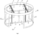
- the revolving door 10 of figure 6 shows a high-traffic solution with two sets of door wings 2, 3 that are arranged in each other's extended direction, wherein the horizontal bars 5 of the carriers 4 of said sets of door wings 2, 3 are parallel.
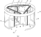
- Figure 7 shows an embodiment of the revolving door 10 wherein three sets of door wings 2, 3 are applied, wherein the horizontal bars 5 of the carriers of said sets of door wings 2, 3 substantially embody the legs of a triangle.
- One attractive feature of the revolving door 10 of the invention is that it enables that the revolving door 10 is convertible while maintaining its dimensions between a configuration with two sets of door wings placed in each other's extended direction as shown in figure 6 , and a door with three sets of door wings that are configured with angles of 120° between said sets of door wings as shown in figure 7 .
- Figure 8 shows again another embodiment of the revolving door 10 of the invention, wherein it has four sets of door wings 2, 3, and wherein the horizontal bars 5 of the carriers 4 of said sets of door wings 2, 3 form the branches of a rectangle.
Landscapes
- Engineering & Computer Science (AREA)
- Mechanical Engineering (AREA)
- Civil Engineering (AREA)
- Structural Engineering (AREA)
- Extensible Doors And Revolving Doors (AREA)
- Lock And Its Accessories (AREA)
- Glass Compositions (AREA)
- Centrifugal Separators (AREA)
- Power-Operated Mechanisms For Wings (AREA)
- Wing Frames And Configurations (AREA)
Description
- The invention relates to a revolving door comprising a wall or walls in which openings for inlet and outlet of persons and/or objects are provided, and rotatable door wings that during use are rotatable around an imaginary central vertical axis in a passage area surrounded by the wall or walls, wherein a carrier or carriers are provided for the door wings.
- Examples of such a revolving door with an imaginary central vertical axis and therefore without a fixed central column are known from for instance
US 5,634,295 , fromEP 0 606 193 , and fromEP 0 715 049 .US 5,634,295 describes a revolving door according to the preamble ofclaim 1. - The dimensions of such known revolving doors without a central column are limited due to their impaired strength in view of the missing central column. Accordingly the known revolving door is limited in its applicability, for instance due to its reduced capability to withstand wind load. Another problem is the inertia of the door which, particularly with larger diameters, may be too high to enable quick starting and stopping of the door. Still another problem is that the door wings of the revolving door without a central column tend to touch the floor due to bending forces in the construction, in view of the constructions' unsatisfactory rigidity.
- It is therefore an object of the invention to provide a revolving door with increased rigidity or stiffness, and wherein the prior art problems are effectively reduced.
- It is another object of the invention to provide a construction of the revolving door according to a modular design, to enable easy mounting and dismounting.
- It is still another object of the invention to provide a revolving door which can be easily converted between configurations with different numbers of door wings while maintaining the outer dimensions of the revolving door.
- According to the invention a revolving door is proposed that is embodied with the features mentioned in one or more of the appended claims.
- In a first aspect of the revolving door of the invention each door wing has a carrier dedicated to such door wing, which carrier comprises a horizontal bar and a vertical bar connected to said horizontal bar, wherein each door wing has two door wing parts that are positioned on opposite sides of the vertical bar of the carrier that supports the concerning door wing. With this construction it is possible to provide sufficient stiffness or rigidity to the revolving door by means of the carrier construction, in spite of the revolving door missing a fixed central column. Moreover an assembly of the supporting construction embodied as a carrier and a door wing or door wing parts supported thereby or suspended therefrom, can be easily handled and makes easy mounting and dismounting possible even in revolving doors of considerable sizes and dimensions. Another big advantage is that the required working height for mounting the revolving door of the invention in a façade of a building can be limited to the bare minimum, independent whether use is made of fixed door wings or slidable door wings.
- Preferably the horizontal bar is arranged perpendicular to the door wing. This provides that loads such as the forces of the wind pushing at the door wing are effectively absorbed in the construction, since the load can be received by the vertical bar and then guided into the horizontal bar in its longitudinal direction. There is therefore hardly any load bearing against the horizontal bar that would provide it with a twisting moment.
- According to the invention, each door wing has two door wing parts that are positioned on opposite sides of the vertical bar of the carrier that supports the concerning door wing. This has the advantage that a wind load pushing at the two door wing parts on respective sides of the vertical bar exactly compensate each other so that no torsional moment acts on the vertical bar of the carrier.
- Suitably the horizontal bar is provided with guide wheels that cooperate with a guide rail in a canopy of the door. The guide rail can have a smaller diameter than the revolving door, which is beneficial to make mounting and dismounting easy of the assembly of the carrier construction with the door wing or door wing parts.
- Commonly the revolving door is provided with a drive or drives for the door wings, in which case it is beneficial that in a construction wherein the door has plural carriers and door wings, the carriers are electronically or mechanically linked. This secures synchronicity in rotation of the door wings, and in case of a mechanical link a single drive can then suffice.
- A reliable construction is provided by arranging that a crossbar connects to the carrier and is arranged perpendicularly with reference to the horizontal bar of the carrier, wherein the door wing is suspended from the crossbar. The crossbar or crossbars can in certain embodiments also be used to provide a mechanical link between the plural carriers of the revolving door.
- The arrangement of the door wing or door wing parts can include all known embodiments of conventional doors. It is for instance possible to apply fixed door wings by arranging that the door wing or door wing parts are fixed to the carrier. It is however also possible that the door wing or door wing parts are collapsible or foldable while remaining connected with or near to the vertical bar of the carrier. In a preferable arrangement the door wing or the door wing parts are slidable. In the latter case it is preferred that the door wing parts are independently slidable.
- Suitably a guide is provided at or near to an end of the vertical bar distant from the horizontal bar for guiding the slidable door wing or door wing parts. This improves the rigidity or stiffness of the construction and is therefore a beneficial feature.
- One particular advantageous feature of the revolving door of the invention is that while maintaining its dimensions the door is convertible between a door configured with two door wings in each other's extended direction, and a door configured with three door wings with angles of 120° between said door wings.
- In the construction wherein the revolving door has two door wings in each other's extended direction, it is beneficial for the sturdiness of the construction that the horizontal bars of the carriers of said door wings are parallel.
- Likewise in the construction wherein the revolving door has three door wings the horizontal bars of the carriers of said door wings substantially embody the legs of a triangle.
- Further in the construction wherein the revolving door has four door wings, the horizontal bars of the carriers of said door wings form the branches of a rectangle.
- The invention will hereinafter be further elucidated with reference to the drawing of an exemplary embodiment of an apparatus according to the invention.
- In the drawing:
-
figure 1 shows a part of a fixed door wing according to the invention; -
figure 2 shows a part of a slidable door wing, comprising door wing parts, according to the invention; -
figure 3 shows a part of a collapsible door wing, comprising door wing parts, according to the invention; -
figure 4 shows a completed door wing of a support instruction and slidable door wing parts as shown infigure 2 ; -
figure 5 shows the door wing offigure 4 suspended from a guide rail of a revolving door; -
figure 6 shows a revolving door of the invention with two door wings; -
figure 7 shows a revolving door of the invention with three door wings; -
figure 8 shows a revolving door of the invention with four door wings; -
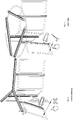
figures 9a and 9b show in detail a guide for a sliding door of the revolving door of the invention; -
figures 10 and 11 show comparatively next to each other a revolving door according to the prior art and a revolving door according to the invention. - Whenever in the figures the same reference numerals are applied, these numerals refer to the same parts.
- Reference is first made to
figures 1 - 3 showing different ways in which a door wing ordoor wing parts door wing parts vertical bar 6 of thecarrier 4. - In
figure 1 anassembly 1 according to the invention is schematically shown, comprising a supporting construction and a door wing ordoor wing parts carrier 4 which is arranged to support or suspend the door wing ordoor wing parts door wing parts vertical bar 6 that is suspended from ahorizontal bar 5 of thecarrier 4. - In
figure 2 it is schematically shown that the door wing ordoor wing parts carrier 4 as symbolized by arrows A. In this arrangement it is preferred -although not shown in the figure-that thevertical bar 6 of thecarrier 4 is at a position 6' distant from thehorizontal bar 5 provided with a guide for the door wing ordoor wing parts - In
figure 3 it is schematically shown that the door wing ordoor wing parts vertical bar 6 of thecarrier 4. - In
figure 4 some more detail is shown of the construction according tofigure 2 , although the additionally shown features can also be applied in the embodiments offigure 1 and figure 3 .Figure 4 shows that acrossbar 7 is connected to thecarrier 4, wherein the door wing ordoor wing parts crossbar 7 which is arranged perpendicular to thecarrier 4. Further it is shown that thehorizontal bar 5 of thecarrier 4 is at its extremities provided withguide wheels 8. - The just mentioned
guide wheels 8 are arranged to cooperate with aguide rail 9 mounted in a canopy of a revolving door according to the invention, a detail of which revolving door is shown byfigure 5 . Infigure 5 a drive by amotor 16 is also shown, whichmotor 16 causes in use that the assembly of thecarrier 4 and thedoor wings figures 6 - 8 showing different embodiments of the revolving door of the invention in which the assembly discussed hereinabove with reference tofigures 1 - 5 is applied. - In all
figures 6 - 8 the revolvingdoor 10 of the invention is shown, comprising a wall orwalls openings passage area 15 surrounded by the wall orwalls rotatable door wings door 10. Accordingly to what has been discussed hereinabove with reference tofigures 1 - 5 each door wing ordoor wing part movable carrier 4 dedicated to such door wing ordoor wing part carrier 4 comprises ahorizontal bar 5 and avertical bar 6. Asfigure 6 clearly shows thehorizontal bar 5 is each time perpendicular to the door wing ordoor wing part door wing parts vertical bar 6 of thecarrier 4 that supports the concerningdoor wing parts fig. 9a and 9b a guide at or near the lower end 6' of thevertical bar 6 is shown which is preferably used when thedoor wing parts figure 2 ). - To improve clarity of the
figures 6 - 8 , particular other features of the assembly as shown infigure 4 and figure 5 are not shown. This for instance applies to thecrossbar 7 that connects to thecarrier 4 and which is arranged perpendicularly with reference to thehorizontal bar 5 of thecarrier 4, and wherein the door wing ordoor wing parts crossbar 7. - The revolving
door 10 offigure 6 shows a high-traffic solution with two sets ofdoor wings horizontal bars 5 of thecarriers 4 of said sets ofdoor wings -
Figure 7 shows an embodiment of the revolvingdoor 10 wherein three sets ofdoor wings horizontal bars 5 of the carriers of said sets ofdoor wings - One attractive feature of the revolving
door 10 of the invention is that it enables that the revolvingdoor 10 is convertible while maintaining its dimensions between a configuration with two sets of door wings placed in each other's extended direction as shown infigure 6 , and a door with three sets of door wings that are configured with angles of 120° between said sets of door wings as shown infigure 7 . -
Figure 8 shows again another embodiment of the revolvingdoor 10 of the invention, wherein it has four sets ofdoor wings horizontal bars 5 of thecarriers 4 of said sets ofdoor wings - Finally it is reminded that the arrangement discussed above with reference to
figure 5 , the construction was shown to be provided with amotor 16 for driving thedoor wings figure 6 - 8 wherein the door each time hasplural carriers 4 and plural sets ofdoor wings respective carriers 4 of the sets ofdoor wings respective door wings door 10. - In the revolving door of the invention one out of plural favourable aspects is that loads such as the forces of the wind pushing at the door wing are effectively absorbed in the construction, since the load can be received by the vertical bar and then guided into the horizontal bar in its longitudinal direction. There is therefore hardly any load bearing against the horizontal bar that would provide it with a twisting moment. This is symbolized in the drawing of
figure 11 which relates to the revolving door of the invention. Conversely and comparativelyfigure 10 depicts the absorbance of a similar load acting on the door wing of a revolving door according to the prior art. In this latter construction there is a similar twisting moment applied to the horizontal bar of the carrier, but this acts transversely to the horizontal bar which is consequently less easily absorbed in the construction. - Although the invention has been discussed in the foregoing with reference to several exemplary embodiments of the revolving door of the invention, the invention is not restricted thereto and can be varied in many ways without departing from the invention as defined by the appended claims. The scope of protection of the invention shall therefore be construed in accordance with the appended claims only.
Claims (13)
- Revolving door (10) comprising a wall or walls (11, 12) in which openings (13, 14) for inlet and outlet of persons and/or objects are provided, and rotatable door wings that during use are rotatable around an imaginary central vertical axis in a passage area (15) surrounded by the wall or walls (11, 12), wherein a carrier or carriers are provided for the door wings, wherein each door wing (2, 3) has a carrier (4) dedicated to such door wing (2, 3), characterized in that said carrier (4) comprises a horizontal bar (5) and a vertical bar (6) connected to said horizontal bar (5), wherein each door wing has two door wing parts (2, 3) that are positioned on opposite sides of the vertical bar (6) of the carrier (4) that supports the concerning door wing.
- Revolving door according to claim 1, characterized in that the horizontal bar (5) is perpendicular to the door wing (2, 3).
- Revolving door according to claim 1 or 2, characterized in that the horizontal bar (5) is provided with guide wheels (8) that cooperate with a guide rail (9) in a canopy of the door.
- Revolving door according to any one of claims 1 - 3, provided with a drive (16) or drives for the door wings (2, 3), characterized in that the door has plural carriers (4) and plural door wings (2, 3), the carriers (4) are electronically or mechanically linked.
- Revolving door according to any one of claims 1 - 4, characterized in that a crossbar (7) connects to the carrier (4) and is arranged perpendicularly with reference to the horizontal bar (5) of the carrier (4), wherein the door wing or door wing parts (2, 3) are suspended from the crossbar (7) .
- Revolving door according to any one of claims 1 - 5, characterized in that the door wing or door wing parts (2, 3) are slidable.
- Revolving door according to any one of claims 1 - 6, characterized in that the door wing parts (2, 3) are independently slidable.
- Revolving door according to claim 6 or 7, characterized in that a guide is provided at or near to an end (6') of the vertical bar (6) distant from the horizontal bar (5) for guiding the slidable door wing or door wing parts (2, 3) .
- Revolving door according to any one of the previous claims 1 - 8, characterized in that the door wing or door wing parts (2, 3) are collapsible or foldable while remaining connected with or near to the vertical bar (6) of the carrier (4) .
- Revolving door according to any one of the previous claims 1 - 9, characterized in that while maintaining its dimensions the door is convertible between a door configured with two door wings in each other's extended direction (fig. 6), and a door configured with three door wings with angles of 120° between said door wings (fig. 7).
- Revolving door according to claim 10, characterized in that it has two door wings in each other's extended direction, the horizontal bars (5) of the carriers (4) of said door wings are parallel.
- Revolving door according to claim 10, characterized in that it has three door wings, the horizontal bars (5) of the carriers (4) of said door wings substantially embody the legs of a triangle.
- Revolving door according to any one of the previous claims 1 - 9, characterized in that it has four door wings, the horizontal bars (5) of the carriers (4) of said door wings form the branches of a rectangle.
Applications Claiming Priority (2)
| Application Number | Priority Date | Filing Date | Title |
|---|---|---|---|
| NL2016678A NL2016678B1 (en) | 2016-04-26 | 2016-04-26 | Revolving door. |
| PCT/NL2017/050262 WO2017188810A1 (en) | 2016-04-26 | 2017-04-24 | Revolving door |
Publications (2)
| Publication Number | Publication Date |
|---|---|
| EP3449080A1 EP3449080A1 (en) | 2019-03-06 |
| EP3449080B1 true EP3449080B1 (en) | 2020-02-12 |
Family
ID=56292843
Family Applications (1)
| Application Number | Title | Priority Date | Filing Date |
|---|---|---|---|
| EP17727970.0A Active EP3449080B1 (en) | 2016-04-26 | 2017-04-24 | Revolving door |
Country Status (9)
| Country | Link |
|---|---|
| US (1) | US10612286B2 (en) |
| EP (1) | EP3449080B1 (en) |
| KR (1) | KR102445659B1 (en) |
| CN (1) | CN107435495B (en) |
| ES (1) | ES2788704T3 (en) |
| MY (1) | MY193074A (en) |
| NL (1) | NL2016678B1 (en) |
| RU (1) | RU2724660C2 (en) |
| WO (1) | WO2017188810A1 (en) |
Families Citing this family (5)
| Publication number | Priority date | Publication date | Assignee | Title |
|---|---|---|---|---|
| NL2016353B1 (en) | 2016-03-02 | 2017-09-20 | Royal Boon Edam Int B V | Revolving door. |
| NL2016678B1 (en) | 2016-04-26 | 2017-11-07 | Royal Boon Edam Int B V | Revolving door. |
| NL2018868B1 (en) | 2017-05-08 | 2018-11-15 | Royal Boon Edam Int B V | Revolving door |
| USD1032880S1 (en) * | 2019-05-17 | 2024-06-25 | Assa Abloy Entrance Systems Ab | Revolving door entrance |
| KR102458137B1 (en) * | 2020-04-03 | 2022-10-24 | 한양대학교 산학협력단 | Revolving door system |
Family Cites Families (35)
| Publication number | Priority date | Publication date | Assignee | Title |
|---|---|---|---|---|
| US798786A (en) * | 1905-03-29 | 1905-09-05 | Lauritz C Hansen | Rotating door. |
| US1024797A (en) | 1908-09-01 | 1912-04-30 | William H Heulings | Car-door. |
| US1184725A (en) * | 1913-02-05 | 1916-05-30 | Claude T Dawes | Door. |
| US1417372A (en) * | 1921-01-08 | 1922-05-23 | Jacob M Friedland | Revolving door |
| US2081774A (en) | 1934-12-17 | 1937-05-25 | Internat Door Company | Revolving door mechanism |
| US3726044A (en) * | 1971-01-26 | 1973-04-10 | G Economou | Revolving door |
| FR2373664A1 (en) * | 1976-12-09 | 1978-07-07 | Saint Gobain | NEW REVERSIBLE GLASS PANEL |
| US4341165A (en) | 1980-05-29 | 1982-07-27 | Calandritti R | Security system including a revolving door |
| SU1164390A1 (en) * | 1983-04-08 | 1985-06-30 | Предприятие П/Я В-8721 | Hinged door |
| SE460678B (en) | 1987-06-18 | 1989-11-06 | Besam Ab | DEVICE AT CARUSAL DOOR |
| DE4211861C2 (en) | 1992-04-08 | 1995-11-16 | Tuerautomation Fehraltorf Ag F | Revolving door |
| DE9208898U1 (en) | 1992-07-03 | 1993-04-01 | Funke & Hellendahl GmbH, 5000 Köln | Revolving door arrangement |
| CH686692A5 (en) * | 1993-01-06 | 1996-05-31 | Schneebeli Metallbau Ag | Carousel Drehtuere. |
| DE4310295A1 (en) * | 1993-03-30 | 1994-10-06 | Tuerautomation Fehraltorf Ag F | Revolving door |
| NL9302235A (en) | 1993-12-22 | 1995-07-17 | Arnold Twigt | Revolving door |
| DE4442191C2 (en) * | 1994-11-28 | 2000-03-09 | Kaba Gallenschuetz Gmbh | Revolving door system |
| NL1002059C2 (en) * | 1996-01-10 | 1997-07-11 | Johannes Severijn Vergouw | Revolving door system. |
| NL1006050C2 (en) * | 1997-05-14 | 1998-11-17 | Boon Edam Bv | Revolving door. |
| FR2781248B1 (en) * | 1998-07-20 | 2000-09-15 | Pentagon Management Ltd | DRUM DOOR WHOSE LATERAL WALLS IN A CIRCLE OF CIRCLE ARE MOBILE TO AUTHORIZE THE CROSSING OF SEVERAL FLOWS WITHOUT MIXING OF THE DIFFERENT ELEMENTS CONSTITUTING THE FLOWS |
| DE19836391C2 (en) * | 1998-08-12 | 2000-08-31 | Dorma Gmbh & Co Kg | Revolving door |
| HUP0104639A3 (en) | 1998-12-16 | 2003-02-28 | Dorma Gmbh & Co Kg | Revolving door with a night closing panel |
| DE19905473C1 (en) | 1999-02-10 | 2001-01-04 | Dorma Gmbh & Co Kg | Carousel door has two fixed curved drum walls set inside rotatable walls and connected by partition wall which provides access on either side |
| NL1015852C2 (en) | 2000-08-01 | 2002-02-05 | Boon Edam Bv | Hinged door. |
| JP2005307716A (en) * | 2004-04-20 | 2005-11-04 | Yoshiichi Sano | Revolving door |
| RU2307909C2 (en) * | 2005-07-12 | 2007-10-10 | Владимир Георгиевич Ковалев | Controlled passage provision device |
| KR100641268B1 (en) * | 2005-07-29 | 2006-11-03 | 왕복권 | Automatic folding structure of rotary blade for automatic turnaround with distributed development structure |
| KR100638281B1 (en) * | 2005-07-29 | 2006-10-30 | 왕복권 | Automatic revolving telegraph with distributed deployment structure of rotating blades |
| JP4840561B2 (en) | 2005-09-06 | 2011-12-21 | 機能性木質新素材技術研究組合 | Method for purifying lignophenol derivatives |
| JP2007224620A (en) * | 2006-02-23 | 2007-09-06 | Matsushita Electric Works Ltd | Revolving door device |
| DE102006053708A1 (en) | 2006-11-15 | 2008-05-29 | BLASI - GMBH Automatische Türanlagen | Revolving door |
| DE102009014869A1 (en) * | 2009-03-30 | 2010-10-07 | Dorma Gmbh + Co. Kg | Sliding hinged door |
| JP2010001735A (en) | 2009-08-25 | 2010-01-07 | Masaaki Kimura | Safety device of revolving door |
| NL2016353B1 (en) | 2016-03-02 | 2017-09-20 | Royal Boon Edam Int B V | Revolving door. |
| NL2016678B1 (en) | 2016-04-26 | 2017-11-07 | Royal Boon Edam Int B V | Revolving door. |
| NL2018868B1 (en) | 2017-05-08 | 2018-11-15 | Royal Boon Edam Int B V | Revolving door |
-
2016
- 2016-04-26 NL NL2016678A patent/NL2016678B1/en active
-
2017
- 2017-04-24 EP EP17727970.0A patent/EP3449080B1/en active Active
- 2017-04-24 ES ES17727970T patent/ES2788704T3/en active Active
- 2017-04-24 MY MYPI2018703891A patent/MY193074A/en unknown
- 2017-04-24 WO PCT/NL2017/050262 patent/WO2017188810A1/en not_active Ceased
- 2017-04-24 KR KR1020187033700A patent/KR102445659B1/en active Active
- 2017-04-24 RU RU2018140935A patent/RU2724660C2/en active
- 2017-04-26 CN CN201710282071.9A patent/CN107435495B/en active Active
-
2018
- 2018-10-26 US US16/171,891 patent/US10612286B2/en active Active
Non-Patent Citations (1)
| Title |
|---|
| None * |
Also Published As
| Publication number | Publication date |
|---|---|
| RU2018140935A (en) | 2020-05-26 |
| ES2788704T3 (en) | 2020-10-22 |
| US20190063131A1 (en) | 2019-02-28 |
| WO2017188810A1 (en) | 2017-11-02 |
| RU2724660C2 (en) | 2020-06-25 |
| NL2016678B1 (en) | 2017-11-07 |
| US10612286B2 (en) | 2020-04-07 |
| RU2018140935A3 (en) | 2020-05-28 |
| KR102445659B1 (en) | 2022-09-20 |
| CN107435495A (en) | 2017-12-05 |
| MY193074A (en) | 2022-09-26 |
| EP3449080A1 (en) | 2019-03-06 |
| KR20180134415A (en) | 2018-12-18 |
| CN107435495B (en) | 2020-06-05 |
Similar Documents
| Publication | Publication Date | Title |
|---|---|---|
| US10612286B2 (en) | Revolving door | |
| RU2519334C2 (en) | Lifter and method of its assembly/disassembly | |
| KR101460354B1 (en) | Maximize the use of space and hanger device | |
| US20180238309A1 (en) | Crane basket | |
| CN102869551B (en) | Vehicle Washing Equipment | |
| ITBO940459A1 (en) | FUN CAROUSEL | |
| EP3772295B1 (en) | Screen lift system for arrangement in furniture or built-in furniture | |
| KR101854388B1 (en) | Zip line of auto drive type | |
| WO2009039848A1 (en) | A handling system for lifting or moving a person, a method for lifting or moving a person and use hereof | |
| JP3208988U (en) | Vertical rotating shelf device with motor-equipped reducer directly fitted to drive shaft | |
| WO2014054972A1 (en) | Ferris wheel, units therefor and device for installing same | |
| KR102209314B1 (en) | Layer laminating apparatus | |
| EP1512605B1 (en) | Cart for carrying and displaying items | |
| KR20130057545A (en) | Operator boarding type ceiling crane | |
| CN208932893U (en) | A kind of transport device | |
| DE102008031811A1 (en) | Serviettenfaltvorrichtung | |
| KR20100137823A (en) | ladder | |
| CN208500033U (en) | Cable drum mounting bracket and drilling machine | |
| KR20220006954A (en) | stage setting apparatus | |
| CN207524412U (en) | A kind of transmission device for building panel processing | |
| CN112240128A (en) | A tower support base and a communication tower | |
| CN215210728U (en) | Banister and supporting beam thereof | |
| CN107675447A (en) | A kind of Rainproof clothes-horse | |
| CN208933563U (en) | A kind of shaft device of moulting automatically | |
| CN223620679U (en) | Lifting mechanism of airing machine and airing machine |
Legal Events
| Date | Code | Title | Description |
|---|---|---|---|
| STAA | Information on the status of an ep patent application or granted ep patent |
Free format text: STATUS: UNKNOWN |
|
| STAA | Information on the status of an ep patent application or granted ep patent |
Free format text: STATUS: THE INTERNATIONAL PUBLICATION HAS BEEN MADE |
|
| PUAI | Public reference made under article 153(3) epc to a published international application that has entered the european phase |
Free format text: ORIGINAL CODE: 0009012 |
|
| STAA | Information on the status of an ep patent application or granted ep patent |
Free format text: STATUS: REQUEST FOR EXAMINATION WAS MADE |
|
| 17P | Request for examination filed |
Effective date: 20181126 |
|
| AK | Designated contracting states |
Kind code of ref document: A1 Designated state(s): AL AT BE BG CH CY CZ DE DK EE ES FI FR GB GR HR HU IE IS IT LI LT LU LV MC MK MT NL NO PL PT RO RS SE SI SK SM TR |
|
| AX | Request for extension of the european patent |
Extension state: BA ME |
|
| DAV | Request for validation of the european patent (deleted) | ||
| DAX | Request for extension of the european patent (deleted) | ||
| GRAP | Despatch of communication of intention to grant a patent |
Free format text: ORIGINAL CODE: EPIDOSNIGR1 |
|
| STAA | Information on the status of an ep patent application or granted ep patent |
Free format text: STATUS: GRANT OF PATENT IS INTENDED |
|
| INTG | Intention to grant announced |
Effective date: 20190828 |
|
| GRAS | Grant fee paid |
Free format text: ORIGINAL CODE: EPIDOSNIGR3 |
|
| GRAA | (expected) grant |
Free format text: ORIGINAL CODE: 0009210 |
|
| STAA | Information on the status of an ep patent application or granted ep patent |
Free format text: STATUS: THE PATENT HAS BEEN GRANTED |
|
| AK | Designated contracting states |
Kind code of ref document: B1 Designated state(s): AL AT BE BG CH CY CZ DE DK EE ES FI FR GB GR HR HU IE IS IT LI LT LU LV MC MK MT NL NO PL PT RO RS SE SI SK SM TR |
|
| REG | Reference to a national code |
Ref country code: GB Ref legal event code: FG4D |
|
| REG | Reference to a national code |
Ref country code: CH Ref legal event code: EP |
|
| REG | Reference to a national code |
Ref country code: AT Ref legal event code: REF Ref document number: 1232324 Country of ref document: AT Kind code of ref document: T Effective date: 20200215 |
|
| REG | Reference to a national code |
Ref country code: IE Ref legal event code: FG4D |
|
| REG | Reference to a national code |
Ref country code: DE Ref legal event code: R096 Ref document number: 602017011711 Country of ref document: DE |
|
| REG | Reference to a national code |
Ref country code: NL Ref legal event code: FP |
|
| REG | Reference to a national code |
Ref country code: SE Ref legal event code: TRGR |
|
| REG | Reference to a national code |
Ref country code: NO Ref legal event code: T2 Effective date: 20200212 |
|
| PG25 | Lapsed in a contracting state [announced via postgrant information from national office to epo] |
Ref country code: RS Free format text: LAPSE BECAUSE OF FAILURE TO SUBMIT A TRANSLATION OF THE DESCRIPTION OR TO PAY THE FEE WITHIN THE PRESCRIBED TIME-LIMIT Effective date: 20200212 Ref country code: FI Free format text: LAPSE BECAUSE OF FAILURE TO SUBMIT A TRANSLATION OF THE DESCRIPTION OR TO PAY THE FEE WITHIN THE PRESCRIBED TIME-LIMIT Effective date: 20200212 |
|
| REG | Reference to a national code |
Ref country code: LT Ref legal event code: MG4D |
|
| PG25 | Lapsed in a contracting state [announced via postgrant information from national office to epo] |
Ref country code: HR Free format text: LAPSE BECAUSE OF FAILURE TO SUBMIT A TRANSLATION OF THE DESCRIPTION OR TO PAY THE FEE WITHIN THE PRESCRIBED TIME-LIMIT Effective date: 20200212 Ref country code: LV Free format text: LAPSE BECAUSE OF FAILURE TO SUBMIT A TRANSLATION OF THE DESCRIPTION OR TO PAY THE FEE WITHIN THE PRESCRIBED TIME-LIMIT Effective date: 20200212 Ref country code: GR Free format text: LAPSE BECAUSE OF FAILURE TO SUBMIT A TRANSLATION OF THE DESCRIPTION OR TO PAY THE FEE WITHIN THE PRESCRIBED TIME-LIMIT Effective date: 20200513 Ref country code: IS Free format text: LAPSE BECAUSE OF FAILURE TO SUBMIT A TRANSLATION OF THE DESCRIPTION OR TO PAY THE FEE WITHIN THE PRESCRIBED TIME-LIMIT Effective date: 20200612 Ref country code: BG Free format text: LAPSE BECAUSE OF FAILURE TO SUBMIT A TRANSLATION OF THE DESCRIPTION OR TO PAY THE FEE WITHIN THE PRESCRIBED TIME-LIMIT Effective date: 20200512 |
|
| REG | Reference to a national code |
Ref country code: ES Ref legal event code: FG2A Ref document number: 2788704 Country of ref document: ES Kind code of ref document: T3 Effective date: 20201022 |
|
| PG25 | Lapsed in a contracting state [announced via postgrant information from national office to epo] |
Ref country code: RO Free format text: LAPSE BECAUSE OF FAILURE TO SUBMIT A TRANSLATION OF THE DESCRIPTION OR TO PAY THE FEE WITHIN THE PRESCRIBED TIME-LIMIT Effective date: 20200212 Ref country code: CZ Free format text: LAPSE BECAUSE OF FAILURE TO SUBMIT A TRANSLATION OF THE DESCRIPTION OR TO PAY THE FEE WITHIN THE PRESCRIBED TIME-LIMIT Effective date: 20200212 Ref country code: SK Free format text: LAPSE BECAUSE OF FAILURE TO SUBMIT A TRANSLATION OF THE DESCRIPTION OR TO PAY THE FEE WITHIN THE PRESCRIBED TIME-LIMIT Effective date: 20200212 Ref country code: LT Free format text: LAPSE BECAUSE OF FAILURE TO SUBMIT A TRANSLATION OF THE DESCRIPTION OR TO PAY THE FEE WITHIN THE PRESCRIBED TIME-LIMIT Effective date: 20200212 Ref country code: PT Free format text: LAPSE BECAUSE OF FAILURE TO SUBMIT A TRANSLATION OF THE DESCRIPTION OR TO PAY THE FEE WITHIN THE PRESCRIBED TIME-LIMIT Effective date: 20200705 Ref country code: DK Free format text: LAPSE BECAUSE OF FAILURE TO SUBMIT A TRANSLATION OF THE DESCRIPTION OR TO PAY THE FEE WITHIN THE PRESCRIBED TIME-LIMIT Effective date: 20200212 Ref country code: EE Free format text: LAPSE BECAUSE OF FAILURE TO SUBMIT A TRANSLATION OF THE DESCRIPTION OR TO PAY THE FEE WITHIN THE PRESCRIBED TIME-LIMIT Effective date: 20200212 Ref country code: SM Free format text: LAPSE BECAUSE OF FAILURE TO SUBMIT A TRANSLATION OF THE DESCRIPTION OR TO PAY THE FEE WITHIN THE PRESCRIBED TIME-LIMIT Effective date: 20200212 |
|
| REG | Reference to a national code |
Ref country code: DE Ref legal event code: R097 Ref document number: 602017011711 Country of ref document: DE |
|
| REG | Reference to a national code |
Ref country code: AT Ref legal event code: MK05 Ref document number: 1232324 Country of ref document: AT Kind code of ref document: T Effective date: 20200212 |
|
| PG25 | Lapsed in a contracting state [announced via postgrant information from national office to epo] |
Ref country code: MC Free format text: LAPSE BECAUSE OF FAILURE TO SUBMIT A TRANSLATION OF THE DESCRIPTION OR TO PAY THE FEE WITHIN THE PRESCRIBED TIME-LIMIT Effective date: 20200212 |
|
| REG | Reference to a national code |
Ref country code: CH Ref legal event code: PL |
|
| PLBE | No opposition filed within time limit |
Free format text: ORIGINAL CODE: 0009261 |
|
| STAA | Information on the status of an ep patent application or granted ep patent |
Free format text: STATUS: NO OPPOSITION FILED WITHIN TIME LIMIT |
|
| 26N | No opposition filed |
Effective date: 20201113 |
|
| PG25 | Lapsed in a contracting state [announced via postgrant information from national office to epo] |
Ref country code: AT Free format text: LAPSE BECAUSE OF FAILURE TO SUBMIT A TRANSLATION OF THE DESCRIPTION OR TO PAY THE FEE WITHIN THE PRESCRIBED TIME-LIMIT Effective date: 20200212 Ref country code: LU Free format text: LAPSE BECAUSE OF NON-PAYMENT OF DUE FEES Effective date: 20200424 Ref country code: LI Free format text: LAPSE BECAUSE OF NON-PAYMENT OF DUE FEES Effective date: 20200430 Ref country code: CH Free format text: LAPSE BECAUSE OF NON-PAYMENT OF DUE FEES Effective date: 20200430 Ref country code: IT Free format text: LAPSE BECAUSE OF FAILURE TO SUBMIT A TRANSLATION OF THE DESCRIPTION OR TO PAY THE FEE WITHIN THE PRESCRIBED TIME-LIMIT Effective date: 20200212 |
|
| PG25 | Lapsed in a contracting state [announced via postgrant information from national office to epo] |
Ref country code: SI Free format text: LAPSE BECAUSE OF FAILURE TO SUBMIT A TRANSLATION OF THE DESCRIPTION OR TO PAY THE FEE WITHIN THE PRESCRIBED TIME-LIMIT Effective date: 20200212 Ref country code: PL Free format text: LAPSE BECAUSE OF FAILURE TO SUBMIT A TRANSLATION OF THE DESCRIPTION OR TO PAY THE FEE WITHIN THE PRESCRIBED TIME-LIMIT Effective date: 20200212 |
|
| PG25 | Lapsed in a contracting state [announced via postgrant information from national office to epo] |
Ref country code: TR Free format text: LAPSE BECAUSE OF FAILURE TO SUBMIT A TRANSLATION OF THE DESCRIPTION OR TO PAY THE FEE WITHIN THE PRESCRIBED TIME-LIMIT Effective date: 20200212 Ref country code: MT Free format text: LAPSE BECAUSE OF FAILURE TO SUBMIT A TRANSLATION OF THE DESCRIPTION OR TO PAY THE FEE WITHIN THE PRESCRIBED TIME-LIMIT Effective date: 20200212 Ref country code: CY Free format text: LAPSE BECAUSE OF FAILURE TO SUBMIT A TRANSLATION OF THE DESCRIPTION OR TO PAY THE FEE WITHIN THE PRESCRIBED TIME-LIMIT Effective date: 20200212 |
|
| PG25 | Lapsed in a contracting state [announced via postgrant information from national office to epo] |
Ref country code: MK Free format text: LAPSE BECAUSE OF FAILURE TO SUBMIT A TRANSLATION OF THE DESCRIPTION OR TO PAY THE FEE WITHIN THE PRESCRIBED TIME-LIMIT Effective date: 20200212 Ref country code: AL Free format text: LAPSE BECAUSE OF FAILURE TO SUBMIT A TRANSLATION OF THE DESCRIPTION OR TO PAY THE FEE WITHIN THE PRESCRIBED TIME-LIMIT Effective date: 20200212 |
|
| PGFP | Annual fee paid to national office [announced via postgrant information from national office to epo] |
Ref country code: NL Payment date: 20250427 Year of fee payment: 9 |
|
| PGFP | Annual fee paid to national office [announced via postgrant information from national office to epo] |
Ref country code: DE Payment date: 20250429 Year of fee payment: 9 |
|
| PGFP | Annual fee paid to national office [announced via postgrant information from national office to epo] |
Ref country code: GB Payment date: 20250428 Year of fee payment: 9 Ref country code: ES Payment date: 20250505 Year of fee payment: 9 |
|
| PGFP | Annual fee paid to national office [announced via postgrant information from national office to epo] |
Ref country code: NO Payment date: 20250429 Year of fee payment: 9 |
|
| PGFP | Annual fee paid to national office [announced via postgrant information from national office to epo] |
Ref country code: BE Payment date: 20250428 Year of fee payment: 9 |
|
| PGFP | Annual fee paid to national office [announced via postgrant information from national office to epo] |
Ref country code: FR Payment date: 20250425 Year of fee payment: 9 |
|
| PGFP | Annual fee paid to national office [announced via postgrant information from national office to epo] |
Ref country code: IE Payment date: 20250428 Year of fee payment: 9 |
|
| PGFP | Annual fee paid to national office [announced via postgrant information from national office to epo] |
Ref country code: SE Payment date: 20250430 Year of fee payment: 9 |