EP3447520A1 - Guidé par des données de correction d'artéfacts dépendant de phase dans un système d'imagerie par résonance magnétique - Google Patents
Guidé par des données de correction d'artéfacts dépendant de phase dans un système d'imagerie par résonance magnétique Download PDFInfo
- Publication number
- EP3447520A1 EP3447520A1 EP17187235.1A EP17187235A EP3447520A1 EP 3447520 A1 EP3447520 A1 EP 3447520A1 EP 17187235 A EP17187235 A EP 17187235A EP 3447520 A1 EP3447520 A1 EP 3447520A1
- Authority
- EP
- European Patent Office
- Prior art keywords
- magnetic resonance
- data
- resonance data
- space
- acquired
- Prior art date
- Legal status (The legal status is an assumption and is not a legal conclusion. Google has not performed a legal analysis and makes no representation as to the accuracy of the status listed.)
- Withdrawn
Links
- 238000012937 correction Methods 0.000 title claims abstract description 94
- 238000002595 magnetic resonance imaging Methods 0.000 title claims description 74
- 230000001131 transforming effect Effects 0.000 claims abstract description 21
- 238000004088 simulation Methods 0.000 claims abstract description 10
- 238000003384 imaging method Methods 0.000 claims description 51
- 238000000034 method Methods 0.000 claims description 37
- 230000009466 transformation Effects 0.000 claims description 26
- 238000012935 Averaging Methods 0.000 claims description 23
- 238000001208 nuclear magnetic resonance pulse sequence Methods 0.000 claims description 18
- 238000004590 computer program Methods 0.000 claims description 11
- 238000005070 sampling Methods 0.000 claims description 8
- 230000001419 dependent effect Effects 0.000 claims description 7
- 230000033001 locomotion Effects 0.000 abstract description 13
- 230000029058 respiratory gaseous exchange Effects 0.000 abstract description 9
- 238000003860 storage Methods 0.000 description 29
- 230000006870 function Effects 0.000 description 12
- 238000010586 diagram Methods 0.000 description 10
- 230000000694 effects Effects 0.000 description 10
- 230000009286 beneficial effect Effects 0.000 description 9
- 230000035945 sensitivity Effects 0.000 description 7
- 238000013507 mapping Methods 0.000 description 6
- 210000004556 brain Anatomy 0.000 description 5
- 230000003287 optical effect Effects 0.000 description 5
- 238000012545 processing Methods 0.000 description 5
- 238000013459 approach Methods 0.000 description 4
- 230000000241 respiratory effect Effects 0.000 description 4
- 230000002123 temporal effect Effects 0.000 description 4
- 230000008901 benefit Effects 0.000 description 3
- 238000004364 calculation method Methods 0.000 description 3
- 230000000747 cardiac effect Effects 0.000 description 3
- 238000009826 distribution Methods 0.000 description 3
- 230000008569 process Effects 0.000 description 3
- 230000009467 reduction Effects 0.000 description 3
- 238000002592 echocardiography Methods 0.000 description 2
- 238000002599 functional magnetic resonance imaging Methods 0.000 description 2
- 238000005259 measurement Methods 0.000 description 2
- 230000000644 propagated effect Effects 0.000 description 2
- 238000012552 review Methods 0.000 description 2
- 238000012800 visualization Methods 0.000 description 2
- 210000000481 breast Anatomy 0.000 description 1
- 238000004422 calculation algorithm Methods 0.000 description 1
- 230000008859 change Effects 0.000 description 1
- 238000004891 communication Methods 0.000 description 1
- 229940079593 drug Drugs 0.000 description 1
- 239000003814 drug Substances 0.000 description 1
- 238000013535 dynamic contrast enhanced MRI Methods 0.000 description 1
- 238000009499 grossing Methods 0.000 description 1
- 238000010438 heat treatment Methods 0.000 description 1
- 238000012804 iterative process Methods 0.000 description 1
- 239000004973 liquid crystal related substance Substances 0.000 description 1
- 230000005415 magnetization Effects 0.000 description 1
- 238000004519 manufacturing process Methods 0.000 description 1
- 230000007246 mechanism Effects 0.000 description 1
- 239000013307 optical fiber Substances 0.000 description 1
- 239000002245 particle Substances 0.000 description 1
- 238000011002 quantification Methods 0.000 description 1
- 239000007787 solid Substances 0.000 description 1
- 238000002560 therapeutic procedure Methods 0.000 description 1
- 210000003813 thumb Anatomy 0.000 description 1
- 238000000844 transformation Methods 0.000 description 1
- 230000000007 visual effect Effects 0.000 description 1
- 238000005303 weighing Methods 0.000 description 1
Images


Classifications
-
- A—HUMAN NECESSITIES
- A61—MEDICAL OR VETERINARY SCIENCE; HYGIENE
- A61B—DIAGNOSIS; SURGERY; IDENTIFICATION
- A61B5/00—Measuring for diagnostic purposes; Identification of persons
- A61B5/05—Detecting, measuring or recording for diagnosis by means of electric currents or magnetic fields; Measuring using microwaves or radio waves
- A61B5/055—Detecting, measuring or recording for diagnosis by means of electric currents or magnetic fields; Measuring using microwaves or radio waves involving electronic [EMR] or nuclear [NMR] magnetic resonance, e.g. magnetic resonance imaging
-
- G—PHYSICS
- G01—MEASURING; TESTING
- G01R—MEASURING ELECTRIC VARIABLES; MEASURING MAGNETIC VARIABLES
- G01R33/00—Arrangements or instruments for measuring magnetic variables
- G01R33/20—Arrangements or instruments for measuring magnetic variables involving magnetic resonance
- G01R33/28—Details of apparatus provided for in groups G01R33/44 - G01R33/64
- G01R33/32—Excitation or detection systems, e.g. using radio frequency signals
- G01R33/36—Electrical details, e.g. matching or coupling of the coil to the receiver
- G01R33/3628—Tuning/matching of the transmit/receive coil
- G01R33/3635—Multi-frequency operation
-
- G—PHYSICS
- G01—MEASURING; TESTING
- G01R—MEASURING ELECTRIC VARIABLES; MEASURING MAGNETIC VARIABLES
- G01R33/00—Arrangements or instruments for measuring magnetic variables
- G01R33/20—Arrangements or instruments for measuring magnetic variables involving magnetic resonance
- G01R33/44—Arrangements or instruments for measuring magnetic variables involving magnetic resonance using nuclear magnetic resonance [NMR]
- G01R33/48—NMR imaging systems
- G01R33/54—Signal processing systems, e.g. using pulse sequences ; Generation or control of pulse sequences; Operator console
- G01R33/56—Image enhancement or correction, e.g. subtraction or averaging techniques, e.g. improvement of signal-to-noise ratio and resolution
- G01R33/561—Image enhancement or correction, e.g. subtraction or averaging techniques, e.g. improvement of signal-to-noise ratio and resolution by reduction of the scanning time, i.e. fast acquiring systems, e.g. using echo-planar pulse sequences
- G01R33/5611—Parallel magnetic resonance imaging, e.g. sensitivity encoding [SENSE], simultaneous acquisition of spatial harmonics [SMASH], unaliasing by Fourier encoding of the overlaps using the temporal dimension [UNFOLD], k-t-broad-use linear acquisition speed-up technique [k-t-BLAST], k-t-SENSE
-
- G—PHYSICS
- G01—MEASURING; TESTING
- G01R—MEASURING ELECTRIC VARIABLES; MEASURING MAGNETIC VARIABLES
- G01R33/00—Arrangements or instruments for measuring magnetic variables
- G01R33/20—Arrangements or instruments for measuring magnetic variables involving magnetic resonance
- G01R33/44—Arrangements or instruments for measuring magnetic variables involving magnetic resonance using nuclear magnetic resonance [NMR]
- G01R33/48—NMR imaging systems
- G01R33/54—Signal processing systems, e.g. using pulse sequences ; Generation or control of pulse sequences; Operator console
- G01R33/56—Image enhancement or correction, e.g. subtraction or averaging techniques, e.g. improvement of signal-to-noise ratio and resolution
- G01R33/565—Correction of image distortions, e.g. due to magnetic field inhomogeneities
Definitions
- the invention relates to phase correction in magnetic resonance imaging, in particular it relates to methods and apparatuses for phase correction in a magnetic resonance imaging system using multiple antenna elements.
- MRI magnetic resonance imaging
- ripples and intensity modulations which are caused by these fluctuations can significantly reduce the quality of the images.
- the invention provides for a magnetic resonance imaging system, a method of operating the magnetic resonance imaging system, and a computer program product in the independent claims. Embodiments are given in the dependent claims.
- aspects of the present invention may be embodied as an apparatus, method or computer program product. Accordingly, aspects of the present invention may take the form of an entirely hardware embodiment, an entirely software embodiment (including firmware, resident software, microcode, etc.) or an embodiment combining software and hardware aspects that may all generally be referred to herein as a "circuit,” “module” or “system.” Furthermore, aspects of the present invention may take the form of a computer program product embodied in one or more computer readable medium(s) having computer executable code embodied thereon.
- the computer readable medium may be a computer readable signal medium or a computer readable storage medium.
- a 'computer-readable storage medium' as used herein encompasses any tangible storage medium which may store instructions which are executable by a processor of a computing device.
- the computer-readable storage medium may be referred to as a computer-readable non-transitory storage medium.
- the computer-readable storage medium may also be referred to as a tangible computer readable medium.
- a computer-readable storage medium may also be able to store data which is able to be accessed by the processor of the computing device.
- Examples of computer-readable storage media include, but are not limited to: a floppy disk, a magnetic hard disk drive, a solid state hard disk, flash memory, a USB thumb drive, Random Access Memory (RAM), Read Only Memory (ROM), an optical disk, a magneto-optical disk, and the register file of the processor.
- Examples of optical disks include Compact Disks (CD) and Digital Versatile Disks (DVD), for example CD-ROM, CD-RW, CD-R, DVD-ROM, DVD-RW, or DVD-R disks.
- the term computer readable-storage medium also refers to various types of recording media capable of being accessed by the computer device via a network or communication link.
- a data may be retrieved over a modem, over the internet, or over a local area network.
- Computer executable code embodied on a computer readable medium may be transmitted using any appropriate medium, including but not limited to wireless, wire line, optical fiber cable, RF, etc., or any suitable combination of the foregoing.
- a computer readable signal medium may include a propagated data signal with computer executable code embodied therein, for example, in baseband or as part of a carrier wave. Such a propagated signal may take any of a variety of forms, including, but not limited to, electro-magnetic, optical, or any suitable combination thereof.
- a computer readable signal medium may be any computer readable medium that is not a computer readable storage medium and that can communicate, propagate, or transport a program for use by or in connection with an instruction execution system, apparatus, or device.
- 'Computer memory' or 'memory' is an example of a computer-readable storage medium.
- Computer memory is any memory which is directly accessible to a processor.
- 'Computer storage' or 'storage' is a further example of a computer-readable storage medium.
- Computer storage is any non-volatile computer-readable storage medium. In some embodiments computer storage may also be computer memory or vice versa.
- a 'processor' as used herein encompasses an electronic component which is able to execute a program or machine executable instruction or computer executable code.
- References to the computing device comprising "a processor” should be interpreted as possibly containing more than one processor or processing core.
- the processor may for instance be a multi-core processor.
- a processor may also refer to a collection of processors within a single computer system or distributed amongst multiple computer systems.
- the term computing device should also be interpreted to possibly refer to a collection or network of computing devices each comprising a processor or processors.
- the computer executable code may be executed by multiple processors that may be within the same computing device or which may even be distributed across multiple computing devices.
- Computer executable code may comprise machine executable instructions or a program which causes a processor to perform an aspect of the present invention.
- Computer executable code for carrying out operations for aspects of the present invention may be written in any combination of one or more programming languages, including an object-oriented programming language such as Java, Smalltalk, C++ or the like and conventional procedural programming languages, such as the "C" programming language or similar programming languages and compiled into machine executable instructions.
- the computer executable code may be in the form of a high-level language or in a pre-compiled form and be used in conjunction with an interpreter which generates the machine executable instructions on the fly.
- the computer executable code may execute entirely on the user's computer, partly on the user's computer, as a stand-alone software package, partly on the user's computer and partly on a remote computer or entirely on the remote computer or server.
- the remote computer may be connected to the user's computer through any type of network, including a local area network (LAN) or a wide area network (WAN), or the connection may be made to an external computer (for example, through the Internet using an Internet Service Provider).
- These computer program instructions may be provided to a processor of a general-purpose computer, special purpose computer, or other programmable data processing apparatus to produce a machine, such that the instructions, which execute via the processor of the computer or other programmable data processing apparatus, create means for implementing the functions/acts specified in the flowchart and/or block diagram block or blocks.
- These computer program instructions may also be stored in a computer readable medium that can direct a computer, other programmable data processing apparatus, or other devices to function in a particular manner, such that the instructions stored in the computer readable medium produce an article of manufacture including instructions which implement the function/act specified in the flowchart and/or block diagram block or blocks.
- the computer program instructions may also be loaded onto a computer, other programmable data processing apparatus, or other devices to cause a series of operational steps to be performed on the computer, other programmable apparatus or other devices to produce a computer implemented process such that the instructions which execute on the computer or other programmable apparatus provide processes for implementing the functions/acts specified in the flowchart and/or block diagram block or blocks.
- a 'user interface' as used herein is an interface which allows a user or operator to interact with a computer or computer system.
- a 'user interface' may also be referred to as a 'human interface device.
- a user interface may provide information or data to the operator and/or receive information or data from the operator.
- a user interface may enable input from an operator to be received by the computer and may provide output to the user from the computer.
- the user interface may allow an operator to control or manipulate a computer and the interface may allow the computer indicate the effects of the operator's control or manipulation.
- the display of data or information on a display or a graphical user interface is an example of providing information to an operator.
- the receiving of data through a keyboard, mouse, trackball, touchpad, pointing stick, graphics tablet, joystick, gamepad, webcam, headset, pedals, wired glove, remote control, and accelerometer are all examples of user interface components which enable the receiving of information or data from an operator.
- a 'hardware interface' as used herein encompasses an interface which enables the processor of a computer system to interact with and/or control an external computing device and/or apparatus.
- a hardware interface may allow a processor to send control signals or instructions to an external computing device and/or apparatus.
- a hardware interface may also enable a processor to exchange data with an external computing device and/or apparatus. Examples of a hardware interface include, but are not limited to: a universal serial bus, IEEE 1394 port, parallel port, IEEE 1284 port, serial port, RS-232 port, IEEE-488 port, Bluetooth connection, Wireless local area network connection, TCP/IP connection, Ethernet connection, control voltage interface, MIDI interface, analog input interface, and digital input interface.
- a 'display' or 'display device' as used herein encompasses an output device or a user interface adapted for displaying images or data.
- a display may output visual, audio, and or tactile data.
- Examples of a display include, but are not limited to: a computer monitor, a television screen, a touch screen, tactile electronic display, Braille screen, Cathode ray tube (CRT), Storage tube, Bi-stable display, Electronic paper, Vector display, Flat panel display, Vacuum fluorescent display (VF), Light-emitting diode (LED) displays, Electroluminescent display (ELD), Plasma display panels (PDP), Liquid crystal display (LCD), Organic light-emitting diode displays (OLED), a projector, and Head-mounted display.
- VF Vacuum fluorescent display
- LED Light-emitting diode
- ELD Electroluminescent display
- PDP Plasma display panels
- LCD Liquid crystal display
- OLED Organic light-emitting diode displays
- Magnetic Resonance (MR) data is defined herein as being the recorded measurements of radio frequency signals emitted by nuclear spins using the antenna of a Magnetic resonance apparatus during a magnetic resonance imaging scan.
- MRF magnetic resonance data is magnetic resonance data.
- Magnetic resonance data is an example of medical image data.
- a Magnetic Resonance Imaging (MRI) image or MR image is defined herein as being the reconstructed two or three-dimensional visualization of anatomic data contained within the magnetic resonance imaging data. This visualization can be performed using a computer.
- the invention provides for a magnetic resonance imaging system.
- the MRI system comprises a main magnet for generating a main magnetic field, i.e. a B0-off-resonance field, within an imaging zone as well as a magnetic field gradient system for generating a spatially dependent gradient magnetic field within the imaging zone.
- the MRI system comprises a radio-frequency system with a set of antenna elements each configured for acquiring magnetic resonance data from the imaging zone.
- the set of antenna elements may e.g. be provided in form of a magnetic resonance imaging coil which comprises multiple antenna elements, i.e. a multi-element magnetic resonance imaging coil.
- the coil functions a receiving coil for performing magnetic resonance imaging, i.e. the antenna elements may function as receiving coil elements.
- a memory of the MRI system stores machine executable instructions and pulse sequence commands.
- the pulse sequence commands are configured for controlling the MRI system to acquire the magnetic resonance data from the imaging zone.
- the pulse sequence commands maybe configured for controlling the magnetic resonance imaging system to acquire the magnetic resonance data according to a parallel imaging protocol.
- the pulse sequence data may for instance be provided in form of commands which may be executed by a processor or it may be provided in form of a timing diagram or timing information which may be converted by a program into commands for controlling the magnetic resonance imaging system.
- a processor is provided for controlling the magnetic resonance imaging system. An execution of the machine executable instructions causes the processor to control the MRI system to perform the following:
- the image data of the antenna elements may be combined by any suitable method appropriate for the chosen sampling scheme, for example sum-of-squares, SENSE, etc.
- the reconstructed combined image data is used to simulate magnetic resonance data acquired by each antenna element.
- This simulation comprises transforming the reconstructed combined image data from image space to k-space, for each antenna element, e.g. using Fourier transformation.
- Transformation from image space to k-space may be performed using Fourier transformation, while transformation from k-space to image space may be performed using inverse Fourier transformation.
- a phase correction factor for the acquired magnetic resonance data of the respective antenna element is determined using the acquired as well as the simulated magnetic resonance data. For this purpose, phase differences are calculated between the acquired magnetic resonance data, or a suitable combination of the acquired data, e.g. average over dynamics, and the simulated magnetic resonance data of the respective antenna element.
- the acquired magnetic resonance data of each element is corrected using the phase correction factor determined for the respective antenna element.
- the invention provides a magnetic resonance imaging system which may enabled to correct for drifts and fluctuations in the B 0 -off-resonance field during an MRI scan from the complex raw data, i.e. the acquired MRI data in k-space, without any additional information, e.g. from an optical camera, breathing belt, or MR navigator etc.
- Main magnetic field fluctuations are rather estimated form the raw MRI k-space data, i.e. a data-driven approach is used.
- Such a data-driven eastimation of field fluctuations may overcome the need for additional sensors, additional MR data acquisitions (navigators) as well as solutions for complicated minimization problems.
- the mechanism behind the correction is that the combination of magnetic resonance data from different channels, i.e. antenna elements, in the image domain and mapping this combined data back to k-space effectively mixed information from neighboring k-space points which may e.g. result in an averaging.
- the resulting averaged data also refered to as simulated magnetic resonances data herein, has a lower phase error because not all neighboring k-space points have experienced the same phase error during data acquisition.
- averaging may at least partly cancel phase errors comprised by the acquired magnetic resonance data.
- This may enable correcting image artefacts caused by B 0 -off-resonance field fluctuations, which may particularly be relevant for gradient-echo scans with long TE, such as for T2*-mapping, susceptibility weighted imaging or quantitative susceptibility mapping.
- Sources of temporal field fluctuations of the main magnetic field may e.g. be caused by a main magnetic field drift of the main magnet during scanning, e.g. due to heating.
- a further source may e.g. be a breathing motion of the subject in the imaging zone or cardiac motion.
- Cardiac motion may be particular relevant in e.g. dynamic contrast enhanced (DCE) breast imaging, where the heart is close to the region of interest.
- DCE dynamic contrast enhanced
- Embodiments may for example be used for artifact reduction for 3D Cartesian gradient echo scans, but may e.g. also be applied to multi-slice 2D scans.
- Other applications for the technique may e.g. be dynamic scans.
- the phase correction factor may be calculated using a single frames or an temporal average of all dynamic frames. The latter has the advantage that the SNR is improved.
- multiple acquisitions of magnetic resonance data of the same k-space lines may be executed.
- SNR of a final magnetic resonance image may be improved by acquirng some or all k-space lines multiple times and average them.
- the phase correction may be applied to the acquired magnetic resonance data e.g. before averaging over repetitions in order to remove the effect of the B 0 -fluctuations.
- Echo planar imaging is a technique which enables very fast imaging, but the k-space is assembled from multiple gradient echoes acquired at different echo times. Thus, off-resonance effects may accumulate during the echo train.
- the correction provided by the proposed magnetic resonace imaging system may as well be applied taking into account the actual echo time of each k-space line.
- the correction may also be applied to dynamic, single-shot EPI scans if the time average is taken as a common reference. This may e.g. be important for functional MRI, where single-shot EPI is the standard sequence and reliable signal intensity of T2* weighted images is a key factor in the quantification of the BOLD effect.
- a single coil magnetic resonance image may be reconstructed for each antenna element, which may e.g. be implemented in form of receiver coils, using the magnetic resonance data acquired by the respective antenna element.
- a combined magnetic resonance image may be formed e.g. as a weighted combination of the single coil images.
- Each of the single coil images may be weighted by a coil sensitivity of the receiver coil which has acquired the magnetic resonance data used to reconstruct the respective single coil image.
- simulated magnetic resonance data may be calculated, e.g. by back-transforming the combined magnetic resonance image weighted by the coil sensitivity of the respective coil.
- Phase deviates between the acquired MRI data and the simulated MRI data may be derived by comparing, e.g. taking the ratio, of the back-transformed k-space magnetic resonance data to the acquired, i.e. measured, magnetic resonance k-space magnetic resonance data.
- phase variations of the main magnetic field are computed from measured magnetic resonance signals from individual receiver coils.
- a combined image that is formed as a weighted superposition of several images reconstructed from data measured by the receiver coils, synthesized, i.e. simulated, k-space data for each of the respective reveiver coils is back-transformed.
- the combined image may provide a good approximation of the actual magnetization distribution in a subject to be examined in the imaging zone assuming Gaussian distributed noise.
- Embodiments may benefially be integrated in methods for parallel imaging.
- a parallel imaging method encompasses imaging methods using a plurality of antenna elements, e.g. receiving coils, for magnetic resonance imaging. Spatial information obtained from an array of antenna elements sampling data in parallel may be used to perform some portion of spatial encoding usually done by gradient fields, typically the phase encoding gradient. Thus, MRI acquisition times may be speeded up without a need for faster switching gradients or for additional RF power deposited.
- parallel imaging may be used to disentangle magnetic resonance signals originating from different spatial locations. Examples of parallel imaging methods are k-space simultaneous acquisition of spatial harmonics (SMASH), generalized autocalibrating partially parallel acquisitions (GRAPPA), and image domain sensitivity encoding (SENSE).
- SMASH spatial harmonics
- GRAPPA generalized autocalibrating partially parallel acquisitions
- SENSE image domain sensitivity encoding
- the SENSE reconstruction technique was introduced by the journal article Pruessmann et al., "SENSE: sensitivity encoding for fast MRI,” Magnetic Resonance in Medicine, 42:952-962 (1999 ).
- the terminology to describe the SENSE reconstruction is well known and has been the subject of many review articles and is present in standard texts on Magnetic Resonance Imaging. For example, " Handbook of MRI Pulse Sequences" by Bernstein et. al., published by Elsevier Academic Press in 2004 contains a review of the SENSE reconstruction technique on pages 527 to 531 .
- the reconstruction of combined image data, the simulation of magnetic resonance data, the determination of the phase correction factor and the correction of the acquired magnetic resonance data are iteratively repeated using the corrected magnetic resonance data in order to further correct the corrected magnetic resonance data until a predefined termination criterion is satisfied.
- the predefined termination criterion may for example be satified, when the calculated phase difference becomes smaller than a predefined threshold or when a predefined maximum number of iteration steps is reached.
- Embodiments may have the beneficial effect of providing an accurate and fast way of fully mapping spatial inhomogeneities of the main magnetic field in a magnetic resonance imaging system, i.e. B 0 -mapping. Iteration may eliminate phase variations due other causes and isolates the phase variations due to spatial variations of the main magnetic field. The drift of the B 0 -off-resonance frequency may thus be deduced from the raw magnetic resonance signal itself in an iterative process which improves the self-consistency of the data set. A small number of iteration steps, for example 3 to 10, like e.g. 4, 5, 6, or 7, may be sufficient to fully remove artefacts due to temporal inhomogeneities, i.e. effects of temporal variations.
- Steps 1 and 2 above describe a multi-channel reconstruction for e.g. a fully sampled Cartesian data sets. In more general terms, they describe a way from multi-channel k-space data to a single reconstructed image (e.g. 2D, 3D or 2D+time, etc), i.e. they describe an image reconstruction algorithm. Depending on the specifics of the data acquisition, e.g. under-sampling of k-space, or half-scan, the actual form of the image reconstruction may differ from the examplary formulas in 1 and 2 above.
- Step 3 describes a simulation data in k-space from an image, i.e. data in image space. Again, the mathematical details of this step depend on the specifics of the acquisition.
- the phase correction may e.g. be calculated iteratively as follows: Let ⁇ 0 ( k x ,k y ,k z ,a ) be the acquired magnetic resonace data of antenna element a in k-space and ⁇ 0 ′ k x k y k z a the magnetic resonance data in k-space simulated from ⁇ 0 , where k x,y,z is the position in k-space and a is the antenna element, i.e. channel, index.
- the data ⁇ 1 ( k x ,k y ,k z ,a ) and ⁇ 1 ′ k x k y k z a are then used to compute a further phase correction ⁇ 1 and so on until a predefined termination criterion is satisfied,.
- the predefined criterion may for example be satified, when a phase correction ⁇ n is reached which is smaller than a predefined threshold ⁇ t or when a predefined maximum number of iteration steps n is reached.
- the aforementioned iteration may converge after a few steps.
- ⁇ i and ⁇ i ′ * may be used in order to calculate the phase correction factor.
- ⁇ i ′ * is the complex conjugate of ⁇ i ′ .
- each antenna element acquires multiple sets of magnetic resonance data from the imaging zone. Each one of the sets is acquired at a different time.
- each antenna element may acquire a first set of magnetic resonance data at a first time, a second set of magnetic resonance data at a second time and so on.
- the transformation of the acquired magnetic resonance data of the antenna elements from k-space to image space comprises for each antenna element averaging the acquired magnetic resonance data of the sets of the respective antenna element over time and transforming the resulting magnetic resonance data from k-space to image space. Or for each antenna element the magnetic resonance data of the sets of the respective antenna element may be transformed and the resulting magnetic resonance data is averaged over time.
- Embodiments may have the beneficial effect of enabling a compensation of fluctuations in case of time series measurements, where multiple sets of magnetic resonance data are acquired at multiple times. This may be beneficial for DCE-MRI oder fMRI/EPI, where data is measured in 2D + time.
- an individual phase correction factor is determined and used for the correction of the magnetic resonance data acquired for the respective point.
- the determination of the individual phase correction factors comprises calculating for each of the points in k-space an individual phase difference between the magnetic resonance data acquired for the respective point and the magnetic resonance data simulated for the respective point.
- Embodiments may have the beneficial effect of for each point in k-space an individual phase correction factor may be determined allowing for a precise phase correction of individual frequencies.
- the phase correction factor is an averaged phase correction factor determined for a subset of the acquired magnetic resonance data and used for the correction of the acquired magnetic resonance data comprised by the subset.
- the determination of the averaged phase correction factor comprises calculating an averaged phase difference by averaging over the phase differences calculated between the acquired magnetic resonance data comprised by the subset and the simulated magnetic resonance data.
- Embodiments may have the beneficial effect depending on the selection of the subset and the details of the averaging procedure used, different ways of balancing the spatial resolution and SNR of the correction may be implemented. For example, points with high signal may contribute more to the final average than points with low signal resulting in an SNR weighted averaging
- the subset comprises a first data selection of the acquired magnetic resonance data which is located on a line along a read-out direction in k-space such that the averaged phase difference is averaged over the read-out direction.
- the read-out direction may be positioned along the direction k x
- the subset comprises a second data selection of the acquired magnetic resonance data of different ones of the antenna elements acquired for the same point in k-space such that the averaged phase difference is averaged over antenna elements.
- the subset comprises a third data selection of the acquired magnetic resonance data which is acquired within a predefined time window such that the averaged phase difference is averaged over the time window.
- the averaging operation includes all k-space points k x , y , z ′ which are acquired within a certain time-window around the acquisition time of k x,y,z .
- weighting factors are assigned to the acquired magnetic resonance data comprised by the subset and used for calculating the averaged phase difference.
- hard weights of 0 or 1 may be used. Such hard weights correspond to a selection of a subset as described above, where all the magnetic resonance data comprised by the subset is weighted equally, while all the magnetic resonance data is neglected for the averaging.
- a plurality of different discrete weighting factors may be introduced. These may e.g. be uniformly distributed over the interval [0;1] or according to a continues function, e.g. according to a Gaussian distribution.
- different data points of the magnetic resonance data maybe weighted differently depending e.g. on their position in k-space, on their time of acquisition, on the antenna element by which it has been acquired, etc.
- the transformation of the reconstructed combined image data from image space to k-space is performed for each dimension of image-space.
- Embodiments may have the beneficial effect that the phase error averaging effect describe above is implemented for all k-space dimensions.
- the transformation of the reconstructed combined image data from image space to k-space is performed for each dimension of image-space except for a subset of dimensions of image space which is kept untransformed such that the resulting simulated magnetic resonance data is located in a hybrid space comprising the subset of dimensions of image space and one or more k-space dimensions.
- a transformation of the acquired magnetic resonance data of each antenna element from k-space to image space is performed for the dimensions of image space comprised by the subset of dimensions such that the resulting transformed acquired magnetic resonance data is located in the hybrid space and the determination of the phase correction factor and the correction of the acquired magnetic resonance data are performed in the hybrid space using the transformed acquired magnetic resonance data.
- the subset of dimensions of image space comprises one dimension of image space, the respective dimension e.g. coinciding with the read-out direction.
- the subset of dimensions of image space comprises multiple dimensions of image space.
- Embodiments may have the beneficial effect that instead of computing the phase correction factor in pure k-space, the phase correction factor is computed in a hybrid space x, k y , k z where the inverse Fourier-transform has been carried out e.g. in readout direction.
- This may have the advantage that the spatial information in x-direction may be directly used in the calculation of the phase correction. If there is e.g. a reason to believe that the Bo fluctuations may vary spatially, the readout direction can be positioned along the direction of the strongest variation and the correction calculation carried out in hybrid space. Spatial smoothing along x may be used to improve SNR analogous to averaging over k x as described above.
- Using the hybrid space may e.g. for a Cartesian magnetic resonance data acquisitions.
- an interlaced sampling scheme in k-space is used for the acquisition of the magnetic resonance data, wherein according to the interlaced sampling scheme magnetic resonance data from neighboring points in k-space comprised by the acquired magnetic resonance data is not acquired in direct succession.
- Embodiments may have the beneficial effect that the sampling of k-space may be optimized in order to maximize the "averaging" effect of the convolution with the Fourier-transform described above.
- the error reduction may become more effective.
- Magnetic resonance data acquired close in time from neighboring k-space points may experience almost the same phase error.
- the averaging effect described above due to combining magnetic resonance data from different antenna elements in the image domain and mapping the combined data back to k-space may be more effective, because data acquired at almost the same time may experience almost the same phase error and thus reduce the averaging effect which is based on different phase error experienced by the k-space points during acquisition.
- the distance between points in k-space for which magnetic resonance data is acquired in direct succession is at least as large as an effective antenna element footprint in k-space.
- Embodiments may have the beneficial effect that they may guarantee an efficient error reduction.
- the effective antenna element footprint in k-space may depends on the parallel imaging capability of the employed coil array which may thus be taken into account.
- the invention provides invention a computer program product comprising machine executable instructions for execution by a processor controlling a magnetic resonance imaging system.
- the magnetic resonance imaging system comprises a main magnet for generating a main magnetic field within an imaging zone, a magnetic field gradient system for generating a spatially dependent gradient magnetic field within the imaging zone, and a radio-frequency system comprising a plurality of antenna elements each configured for acquiring magnetic resonance data from the imaging zone.
- the magnetic resonance imaging system may further comprise a memory for storing machine executable instructions and pulse sequence commands, wherein the pulse sequence commands are configured for controlling the magnetic resonance imaging system to acquire the magnetic resonance data from the imaging zone.
- An execution of the machine executable instructions causes the processor to control the magnetic resonance imaging system to acquire magnetic resonance data from the imaging zone by each of the antenna elements.
- the MRI sytsem reconstructs combined image data.
- the reconstruction comprises transforming the acquired magnetic resonance data of the antenna elements from k-space to image space, e.g. using inverse Fourier transformation, and combining the resulting image data of the antenna elements.
- Magnetic resonance data acquired by each antenna element is simulated using the reconstructed combined image data.
- the simulation comprises transforming the reconstructed combined image data from image space to k-space, e.g. using Fourier transformation.
- the MRI system determines a phase correction factor for the acquired magnetic resonance data of the respective antenna element.
- the determination comprises calculating phase differences between the acquired magnetic resonance data and the simulated magnetic resonance data of the respective antenna element.
- the acquired magnetic resonance data of each respective antenna element is then corrected using the phase correction factor determined for the respective antenna element.
- the invention provides a method of operating a magnetic resonance imaging system as described above.
- the method comprises acquiring magnetic resonance data from the imaging zone by each of the antenna elements.
- Combined image data is reconstructed.
- the reconstruction comprises transforming the acquired magnetic resonance data of the antenna elements from k-space to image space, e.g. using inverse Fourier transformation, and combining the resulting image data of the antenna elements.
- Magnetic resonance data acquired by each antenna element is simulated using the reconstructed combined image data.
- the simulation comprises transforming the reconstructed combined image data from image space to k-space, e.g. using Fourier transformation.
- a phase correction factor is determined for the acquired magnetic resonance data of the respective antenna element.
- the determination comprises calculating phase differences between the acquired magnetic resonance data and the simulated magnetic resonance data of the respective antenna element.
- the acquired magnetic resonance data of each antenna element is corrected using the phase correction factor determined for the respective antenna element.
- Fig. 1 shows an example of a magnetic resonance imaging system 100.
- the magnetic resonance imaging system 100 comprises a main magnet 104.
- the magnet 104 is a superconducting cylindrical type magnet 104 with a bore 106 through it.
- the use of different types of magnets is also possible for instance it is also possible to use both a split cylindrical magnet and a so called open magnet.
- a split cylindrical magnet is similar to a standard cylindrical magnet, except that the cryostat has been split into two sections to allow access to the iso-plane of the magnet, such magnets may for instance be used in conjunction with charged particle beam therapy.
- An open magnet has two magnet sections, one above the other with a space in-between that is large enough to receive a subject: the arrangement of the two sections area similar to that of a Helmholtz coil.
- Open magnets are popular, because the subject is less confined. Inside the cryostat of the cylindrical magnet there is a collection of superconducting coils. Within the bore 106 of the cylindrical magnet 104 there is an imaging zone 108 where the magnetic field is strong and uniform enough to perform magnetic resonance imaging.
- the magnetic field gradient coils 110 are intended to be representative. Typically, magnetic field gradient coils 110 contain three separate sets of coils for spatially encoding in three orthogonal spatial directions.
- a magnetic field gradient power supply supplies current to the magnetic field gradient coils. The current supplied to the magnetic field gradient coils 110 is controlled as a function of time and may be ramped or pulsed.
- the body coil 114 may be e.g. be a quadrature body coil (QBC) or a whole-body coil.
- the body coil 114 is shown as being connected to a transceiver 116.
- body coil 114 may be a whole-body coil and connected to a whole-body coil radio frequency amplifier and/or receiver, however this is not shown in this example. If both a transmitter and a receiver 116 are connected to the whole-body coil 114, a means for switching between the transmit and receive mode may be provided. For example, a circuit with a pin diode may be used to select the transmit or receive mode.
- a subject support 120 supports a subject 118 within the imaging zone.
- a transceiver 122 is shown as being connected to a radio-frequency system comprising a magnetic resonance imaging coil 124.
- the magnetic resonance imaging coil 124 is a surface coil comprising multiple antenna elements 126.
- the transceiver 122 is operable for sending and receiving individual RF signals to the individual antenna elements 126.
- the transceiver 116 and the transceiver 122 are shown as being separate units. However, in other examples the units 116 and 122 could be combined.
- the transceiver 116, the transceiver 122, and the magnetic field gradient coil power supply 112 are shown as being connected to a hardware interface 132 of a computer 130.
- the computer 130 is further shown as containing a processor 133 which is operable for executing the machine-readable instructions.
- the computer 130 is further shown as comprising a user interface 134, computer storage 136 and computer memory 138 which are all accessible and connected to the processor 133.
- the computer storage 136 is shown as containing one of more pulse sequences 140.
- the pulse sequences 140 are either instructions or data which can be converted into instructions which enable the processor 133 to acquire magnetic resonance data using the magnetic resonance imaging system 100.
- the computer storage is further shown as containing magnetic resonance data 142 acquired by the antenna elements 126.
- the computer storage is further shown as containing reconstructed combined image data 144.
- the reconstructed combined image data 144 is calculated using the acquired magnetic resonance data 142. This may be performed using several different techniques. It may e.g. be done using the SENSE protocol.
- the computer storage 136 is further shown as containing simulated magnetic resonance data 146 simulated using the reconstructed combined image data 144.
- simulated magnetic resonance data 146 simulated using the reconstructed combined image data 144.
- a set of coil sensitivities of the set antenna elements 126 may be provided by the computer storage 136 as well.
- the computer storage may further comprise a definition of a set of points in Fourier space which are used as points for averaging the acquired magnetic resonance data 142 and the simulated magnetic resonance data 146.
- the computer storage 136 is further shown as containing corrected magnetic resonance data 148 which is calculated from the acquired magnetic resonance data 142 using the simulated magnetic resonance data 146 in order to determine a phase correction factor for the acquired magnetic resonance data 142.
- the computer storage 136 is shown as containing a diagnostic magnetic resonance image 150 which is reconstructed using the corrected magnetic resonance data 148.
- the diagnostic magnetic resonance image 150 may e.g. be reconstructed based on a parallel imaging magnetic resonance technique using the corrected magnetic resonance data 148.
- a set of coil sensitivities of antenna elements 126 maybe used.
- the body coil 114 is not present. In other examples, the body coil 114 is used to acquire part of the magnetic resonance data 142.
- the computer memory 138 is shown as being a control module 160.
- the control module 160 contains computer-executable code or instructions which enable the processor 133 to control the operation and function of the magnetic resonance imaging system. For instance, the control module 160 may work in conjunction with the pulse sequences 140 to acquire the various magnetic resonance data.
- the computer memory 138 is shown as further containing an imaging reconstruction Fourier transform module 162 and phase correction module 164. These two modules 162, 164 contain computer-executable code which enable the processor 133 to perform one or more of the methods shown in Figs. 2 to 3 . Furthermore, depending on the method used, the phase correction module 164 may also perform an averaging of magnetic resonance data 142, 146.
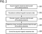
- Fig. 2 shows a flowchart which illustrates a method of operating the magnetic resonance imaging system 100 shown in Fig. 1 .
- magnetic resonance data 142 is acquired from the imaging zone 108 by each of the antenna elements 126.
- the control module 160 may work in conjunction with the pulse sequences 140 to acquire the magnetic resonance data 142.
- magnetic resonance data may also be acquired by the body coil, i.e. the body coil may provide the functionality of an antenna element.
- combined image data 144 is reconstructed from the magnetic resonance data 142.
- the acquired magnetic resonance data 142 of the antenna elements 126 is transformed from k-space to image space using inverse Fourier transformation. The transformation may be executed using the transformation module 162.
- the resulting image data of two or more of the antenna elements 126 in image space is combined in receive the combined image data 146.
- the resulting image data of all the antenna elements 126 is combined.
- a 3D imge is reconstructed.
- one or more 2D images e.g. a stack of 2D images, are reconstructed.
- a parallel imaging protocol like e.g. the SENSE protocol maybe used.
- multiple sets of magnetic resonace data 142 are acquired by each antenna element 126, each set of a given antenna element 126 being acquired at another time.
- the transformation may comprise averaging the acquired magnetic resonance data 142 of each antenna elements 126 over time, e.g. over the sets of magnetic resonace data 142 of the respective antenna element 126, and transforming the result from k-space to image space, or first transforming to image space followed by averaging over time.
- the magnetic resonance data acquired by each antenna element is simulated using the reconstructed combined image data 144.
- the reconstructed combined image data 144 is transformed by the transformation module 162 from image space to k-space using Fourier transformation. According to embodiments all dimensions of image space are tranformed into k-space dimensions, i.e. a full basis change transforming all coordinates of k-space is perfomed. According to other embodiments, only a subset of coordinates of k-space is transforemed, while the remaining coordiantes of k-space are kept untransformed.
- the reconstructed combined image data 144 are transformed into a hybrid space, i.e. a space e.g. comprising at least one image space dimension and one or more k-space dimensions.
- the simulated magnetic resonance data 146 may be the result of one the above transformations.
- a phase correction factor is determined by the phase correction module 164.
- the determination comprises calculating phase differences between the acquired magnetic resonance data 142 and the simulated magnetic resonance data 146 of the respective antenna element.
- the phase difference may calculated by computing the ratio of the acquired magnetic resonance data 142 and the simulated magnetic resonance data 146, e.g. for each data point in k-space or hybrid space.
- the product of the acquired magnetic resonance data 142 and the complex conjugate of the simulated magnetic resonance data 146 is computed, e.g. for each data point in k-space or hybrid space.
- ratio or product is averaged.
- the acquired magnetic resonance data 142 and the simulated magnetic resonance data 146 is averaged over the read-out direction, i.e. over k x in case of the full k-space or x in case of the hybrid space.
- it is averaged over channels, i.e. the magnetic resonance data 146 simulated for the different antenna elements 126 as well as the magnetic resonance data 142 acquired by the different antenna elements 126 is averaged over the antenna elements.
- it is averaged over time.
- Magnetic resonance data 142, 146 of k-space points for which the magnetic resonance data 142 has been acquired within a predefined time-window are averaged.
- all the acquired magnetic resonance data 142 and the simulated magnetic resonance data 146 which is averaged maybe weighted equally or the data points may be assigned with different weightening factors. For example, a Gaussian distribution of weighing factors may be assigned to the data points, when being averaged.
- a phase correction factor may be determined for each data point comprised by the acquired magnetic resonance data 142. However, averaging may result in equal phase correction factors for one or more of the dta points comprsied by the acquired magnetic resonance data 142.
- step 208 the phase correction factor calculated in step 206 is used by the phase correction module 164 to correct the acquired magnetic resonance data 142 of each antenna element.
- Each data point comprised by the acquired magnetic resonance data 142 may be corrected using the phase correction factor calculated for the respective data point resulting in the corrected magnetic resonance data 148.
- Fig. 3 shows a flowchart of an iterative implementation of the method of v 2.
- the correction of the acquired magnetic resonance data 142 i.e. the calculation of the corrected magnetic resonance data 148
- the termination criterion may e.g. require that the phase correction factor determined in step 206 is smaller than a predefined threshold or that a predefined maximum number of iteration steps is reached.
- the method is continued with step 212.
- the acquired magnetic resonance data 142 is replaced by the corrected magnetic resonance data 146 for the further procedure.
- steps 201 to 208 of the method are repeated with the corrected magnetic resonance data 146 instead of the acquired magnetic resonance data 142.
- the repetition which results in new corrected magnetic resonance data
- it is checked in step 210 for the new corrected magnetic resonance data, whether the termination criterion is satisfied, e.g. whether the phase correction factor determined by repeating steps 201 to 208 is smaller than the predefined threshold.
- the steps 202 to 208 are iteratively repeated until a correction factor is determined which is smaller than the predefined threshold.
- the steps 202 may be repeated until each of the phase correction factors are smaller than the threshold.
- step 214 the correct magnetic resonance data last calculated is used to reconstruct a diagnostic magnetic resonance image 150.
- the diagnostic magnetic resonance image 150 may be reconstructed from the corrrected magnetic resonance data last calculated using a parallel imagine protocol, like e.g. the SENSE protocol.
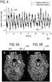
- Fig. 4 shows a diagram 500 which illustrates the correlation of the estimated phase correction 502 with the signal of a respiratory bellows 504, i.e. the breathing motion of a subject.
- Physiologic sources like e.g. a breathing motion, may introduce drifts or fluctuations of the main magnetic filed, i.e. the B 0 -off-resonance field, which may have a significant impact on image quality. They may e.g. lead to ghosting and other artefacts.
- the phase correction factor 502 determined by the method of Figs 2 and 3 in case of an main magnetic felad which comprises inhomogeneties induced by breathing motions of the subject may correspond to the respective breathing motion 504. Therefore, phase artefacts induced by breathing motion may efficiently be corrected using the data-driven correction method described above e.g. with regard of FIGs. 2 and 3 .
- FIGs. 5A and 5B show the impact on the estimated phase correction on a T 2 *-weighted, gradient-echo brain image.
- Fig. 5A shows a diagnostic magnetic resonance image which has been recontructed using the uncorrected magnetic reonance data acquired by the antenna elements.
- Fig. 5B shows a diagnostic magnetic resonance image which has been recontructed using the corrected magnetic resonance data calculated according to one or more of the aformentioned embodiments. Artifacts due to B 0 -fluctuation are present in Fig.
- a computer program may be stored/distributed on a suitable medium, such as an optical storage medium or a solid-state medium supplied together with or as part of other hardware, but may also be distributed in other forms, such as via the Internet or other wired or wireless telecommunication systems. Any reference signs in the claims should not be construed as limiting the scope.
Landscapes
- Physics & Mathematics (AREA)
- Health & Medical Sciences (AREA)
- Nuclear Medicine, Radiotherapy & Molecular Imaging (AREA)
- General Health & Medical Sciences (AREA)
- Radiology & Medical Imaging (AREA)
- Engineering & Computer Science (AREA)
- High Energy & Nuclear Physics (AREA)
- Condensed Matter Physics & Semiconductors (AREA)
- General Physics & Mathematics (AREA)
- Signal Processing (AREA)
- Life Sciences & Earth Sciences (AREA)
- Biophysics (AREA)
- Pathology (AREA)
- Biomedical Technology (AREA)
- Heart & Thoracic Surgery (AREA)
- Medical Informatics (AREA)
- Molecular Biology (AREA)
- Surgery (AREA)
- Animal Behavior & Ethology (AREA)
- Public Health (AREA)
- Veterinary Medicine (AREA)
- Magnetic Resonance Imaging Apparatus (AREA)
Priority Applications (7)
| Application Number | Priority Date | Filing Date | Title |
|---|---|---|---|
| EP17187235.1A EP3447520A1 (fr) | 2017-08-22 | 2017-08-22 | Guidé par des données de correction d'artéfacts dépendant de phase dans un système d'imagerie par résonance magnétique |
| PCT/EP2018/072078 WO2019038147A1 (fr) | 2017-08-22 | 2018-08-15 | Correction dirigée par des données d'artefacts dépendants d'une phase dans un système d'imagerie par résonance magnétique |
| RU2020111530A RU2764643C2 (ru) | 2017-08-22 | 2018-08-15 | Управляемая потоком данных коррекция фазозависимых артефактов в системе магнитно-резонансной томографии |
| EP18762455.6A EP3673282B1 (fr) | 2017-08-22 | 2018-08-15 | Correction, guidée par des données, d'artéfacts dépendant de la phase dans un système d'imagerie par résonance magnétique |
| JP2020511195A JP6925512B2 (ja) | 2017-08-22 | 2018-08-15 | 磁気共鳴イメージングシステムにおける位相依存アーチファクトのデータ駆動型補正 |
| CN201880068610.1A CN111263896B (zh) | 2017-08-22 | 2018-08-15 | 在磁共振成像系统中对相位相关的伪影的数据驱动的校正 |
| US16/639,770 US11061097B2 (en) | 2017-08-22 | 2018-08-15 | Data driven correction of phase depending artefacts in a magnetic resonance imaging system |
Applications Claiming Priority (1)
| Application Number | Priority Date | Filing Date | Title |
|---|---|---|---|
| EP17187235.1A EP3447520A1 (fr) | 2017-08-22 | 2017-08-22 | Guidé par des données de correction d'artéfacts dépendant de phase dans un système d'imagerie par résonance magnétique |
Publications (1)
| Publication Number | Publication Date |
|---|---|
| EP3447520A1 true EP3447520A1 (fr) | 2019-02-27 |
Family
ID=59683477
Family Applications (2)
| Application Number | Title | Priority Date | Filing Date |
|---|---|---|---|
| EP17187235.1A Withdrawn EP3447520A1 (fr) | 2017-08-22 | 2017-08-22 | Guidé par des données de correction d'artéfacts dépendant de phase dans un système d'imagerie par résonance magnétique |
| EP18762455.6A Active EP3673282B1 (fr) | 2017-08-22 | 2018-08-15 | Correction, guidée par des données, d'artéfacts dépendant de la phase dans un système d'imagerie par résonance magnétique |
Family Applications After (1)
| Application Number | Title | Priority Date | Filing Date |
|---|---|---|---|
| EP18762455.6A Active EP3673282B1 (fr) | 2017-08-22 | 2018-08-15 | Correction, guidée par des données, d'artéfacts dépendant de la phase dans un système d'imagerie par résonance magnétique |
Country Status (6)
| Country | Link |
|---|---|
| US (1) | US11061097B2 (fr) |
| EP (2) | EP3447520A1 (fr) |
| JP (1) | JP6925512B2 (fr) |
| CN (1) | CN111263896B (fr) |
| RU (1) | RU2764643C2 (fr) |
| WO (1) | WO2019038147A1 (fr) |
Families Citing this family (3)
| Publication number | Priority date | Publication date | Assignee | Title |
|---|---|---|---|---|
| EP3916417A1 (fr) * | 2020-05-28 | 2021-12-01 | Koninklijke Philips N.V. | Correction d'images par résonance magnétique utilisant plusieurs configurations de système d'imagerie par résonance magnétique |
| DE102020209382A1 (de) * | 2020-07-24 | 2022-01-27 | Siemens Healthcare Gmbh | Verfahren zur Aufnahme von Messdaten mittels einer Magnetresonanzanlage mit einer Korrektur der verwendeten k-Raumtrajektorien |
| CN114325528B (zh) * | 2021-12-25 | 2024-01-02 | 沈阳工业大学 | 一种磁共振成像方法及相关设备 |
Citations (2)
| Publication number | Priority date | Publication date | Assignee | Title |
|---|---|---|---|---|
| US5759152A (en) * | 1996-10-02 | 1998-06-02 | Mayo Foundation For Medical Education And Research | Phase-aligned NMR surface coil image reconstruction |
| WO2011106649A1 (fr) * | 2010-02-25 | 2011-09-01 | Mcw Research Foundation, Inc. | Procédé d'imagerie simultanée par résonance magnétique à tranches multiples à l'aide de bobines réceptrices à canaux uniques et multiples |
Family Cites Families (26)
| Publication number | Priority date | Publication date | Assignee | Title |
|---|---|---|---|---|
| US5929638A (en) * | 1996-08-07 | 1999-07-27 | U.S. Philips Corporation | MR method and device for carrying out the method |
| KR100768677B1 (ko) * | 1999-05-20 | 2007-10-23 | 코닌클리케 필립스 일렉트로닉스 엔.브이. | 서브-샘플링에 의한 자기 공명 영상 형성 방법 |
| AU1811201A (en) * | 1999-12-03 | 2001-06-12 | Johns Hopkins University, The | Apparatus and methods for spatial encoded mri |
| US7408345B2 (en) * | 2006-02-06 | 2008-08-05 | The Board Of Trustees Of The Leland Stanford Junior University | Generalized MRI reconstruction with correction for multiple image distortion |
| EP2044454A1 (fr) * | 2006-07-18 | 2009-04-08 | Koninklijke Philips Electronics N.V. | Suppression d'artefact dans une irm à plusieurs bobines |
| US7619411B2 (en) * | 2006-08-28 | 2009-11-17 | Wisconsin Alumni Research Foundation | Generalized method for MRI chemical species separation using arbitrary k-space trajectories |
| DE102007054863B4 (de) * | 2007-11-16 | 2009-09-10 | Siemens Ag | Verfahren und Computersoftwareprodukt zur Magnet-Resonanz-Bildgebung auf Basis einer partiellen parallelen Akquisition (PPA) |
| US8077955B2 (en) * | 2009-03-19 | 2011-12-13 | Kabushiki Kaisha Toshiba | B1 mapping in MRI system using k-space spatial frequency domain filtering |
| CN102362192A (zh) * | 2009-03-25 | 2012-02-22 | 皇家飞利浦电子股份有限公司 | 磁共振成像中针对刚性、非刚性、平移、旋转和跨平面运动的运动检测和校正 |
| EP2696212A1 (fr) * | 2012-08-06 | 2014-02-12 | Universitätsklinikum Freiburg | Procédé et appareil permettant d'accélérer l'imagerie par résonance magnétique |
| CN102798829B (zh) * | 2012-08-14 | 2015-04-22 | 深圳先进技术研究院 | 基于机器学习的并行磁共振成像grappa方法 |
| DE102012216327B4 (de) * | 2012-09-13 | 2021-01-14 | Siemens Healthcare Gmbh | Verfahren zur Erfassung einer Bewegung eines Patienten während einer medizinischen Bildgebungsuntersuchung |
| JP6317756B2 (ja) * | 2012-12-06 | 2018-04-25 | コーニンクレッカ フィリップス エヌ ヴェKoninklijke Philips N.V. | 副作用の少ない局所アーチファクトの低減 |
| US9726742B2 (en) * | 2013-02-01 | 2017-08-08 | Regents Of The University Of Minnesota | System and method for iteratively calibrated reconstruction kernel for accelerated magnetic resonance imaging |
| CN103961097B (zh) * | 2013-02-04 | 2016-08-31 | 上海联影医疗科技有限公司 | 一种磁共振扫描短te成像方法及磁共振扫描系统 |
| CN103278784B (zh) * | 2013-06-02 | 2015-06-17 | 南方医科大学 | 一种多约束滑动窗的磁共振并行成像方法 |
| JP6479782B2 (ja) * | 2013-10-08 | 2019-03-06 | コーニンクレッカ フィリップス エヌ ヴェKoninklijke Philips N.V. | 補正マルチスライス磁気共鳴イメージング |
| DE102013221940B3 (de) * | 2013-10-29 | 2015-02-12 | Siemens Aktiengesellschaft | Kompensation von Störfeldern in Magnetresonanzbildern mittels einer Matrix-Methode |
| US10353023B2 (en) * | 2013-12-10 | 2019-07-16 | Koninklijke Philips N.V. | Calculating MRI RF coil sensitivities using interpolation into an enlarged field of view |
| WO2015144568A1 (fr) * | 2014-03-24 | 2015-10-01 | Koninklijke Philips N.V. | Imagerie à résonance magnétique propeller |
| RU2672151C2 (ru) * | 2014-03-28 | 2018-11-12 | Конинклейке Филипс Н.В. | Коррекция посторонних эхосигналов epi |
| RU2685057C2 (ru) * | 2014-03-31 | 2019-04-16 | Конинклейке Филипс Н.В. | Магнитно-резонансная томография с катушками обнаружения рч шумов |
| DE102015107347A1 (de) * | 2015-05-11 | 2016-11-17 | Universitätsspital Basel | Ein magnetresonanztomographie-verfahren mit asymmetrischer radialer akquisition von k-raum-daten |
| JP6763892B2 (ja) * | 2015-06-26 | 2020-09-30 | コーニンクレッカ フィリップス エヌ ヴェKoninklijke Philips N.V. | 位相補正したディクソン磁気共鳴撮像 |
| CN106597333B (zh) * | 2016-12-30 | 2019-05-31 | 上海联影医疗科技有限公司 | 一种磁共振并行成像方法及磁共振成像系统 |
| US11009577B2 (en) * | 2018-06-01 | 2021-05-18 | Regents Of The University Of Minnesota | System and method for Nyquist ghost correction in medical imaging |
-
2017
- 2017-08-22 EP EP17187235.1A patent/EP3447520A1/fr not_active Withdrawn
-
2018
- 2018-08-15 RU RU2020111530A patent/RU2764643C2/ru active
- 2018-08-15 WO PCT/EP2018/072078 patent/WO2019038147A1/fr unknown
- 2018-08-15 JP JP2020511195A patent/JP6925512B2/ja active Active
- 2018-08-15 CN CN201880068610.1A patent/CN111263896B/zh active Active
- 2018-08-15 EP EP18762455.6A patent/EP3673282B1/fr active Active
- 2018-08-15 US US16/639,770 patent/US11061097B2/en active Active
Patent Citations (2)
| Publication number | Priority date | Publication date | Assignee | Title |
|---|---|---|---|---|
| US5759152A (en) * | 1996-10-02 | 1998-06-02 | Mayo Foundation For Medical Education And Research | Phase-aligned NMR surface coil image reconstruction |
| WO2011106649A1 (fr) * | 2010-02-25 | 2011-09-01 | Mcw Research Foundation, Inc. | Procédé d'imagerie simultanée par résonance magnétique à tranches multiples à l'aide de bobines réceptrices à canaux uniques et multiples |
Non-Patent Citations (5)
| Title |
|---|
| ALEXEY A. SAMSONOV ET AL: "POCS-enhanced correction of motion artifacts in parallel MRI", MAGNETIC RESONANCE IN MEDICINE, vol. 63, no. 4, 1 April 2010 (2010-04-01), pages 1104 - 1110, XP055087023, ISSN: 0740-3194, DOI: 10.1002/mrm.22254 * |
| BERNSTEIN: "Handbook of MRI Pulse Sequences", 2004, ELSEVIER ACADEMIC PRESS, article "contains a review of the SENSE reconstruction technique", pages: 527 - 531 |
| DJ LARKMAN ET AL: "Consistency Based Ghost Busting (CBGB)", PROCEEDINGS OF THE INTERNATIONAL SOCIETY FOR MAGNETIC RESONANCE IN MEDICINE, ISMRM, JOINT ANNUAL MEETING ISMRM-ESMRMB, BERLIN, GERMANY, 19-25 MAY 2007, 5 May 2007 (2007-05-05), pages 987, XP040600166 * |
| PRUESSMANN ET AL.: "SENSE: sensitivity encoding for fast MRI", MAGNETIC RESONANCE IN MEDICINE, vol. 42, 1999, pages 952 - 962, XP000866655, DOI: doi:10.1002/(SICI)1522-2594(199911)42:5<952::AID-MRM16>3.0.CO;2-S |
| STEFAN SKARE ET AL: "An auto-calibrated, angularly continuous, two-dimensional GRAPPA kernel for propeller trajectories", MAGNETIC RESONANCE IN MEDICINE, vol. 60, no. 6, 24 November 2008 (2008-11-24), pages 1457 - 1465, XP055012933, ISSN: 0740-3194, DOI: 10.1002/mrm.21788 * |
Also Published As
| Publication number | Publication date |
|---|---|
| CN111263896A (zh) | 2020-06-09 |
| US20200209331A1 (en) | 2020-07-02 |
| RU2020111530A3 (fr) | 2021-09-23 |
| EP3673282B1 (fr) | 2021-07-21 |
| US11061097B2 (en) | 2021-07-13 |
| RU2764643C2 (ru) | 2022-01-19 |
| JP2020531140A (ja) | 2020-11-05 |
| WO2019038147A1 (fr) | 2019-02-28 |
| CN111263896B (zh) | 2022-09-06 |
| EP3673282A1 (fr) | 2020-07-01 |
| RU2020111530A (ru) | 2021-09-23 |
| JP6925512B2 (ja) | 2021-08-25 |
Similar Documents
| Publication | Publication Date | Title |
|---|---|---|
| US9317917B2 (en) | Method, reconstruction device, and magnetic resonance apparatus for reconstructing magnetic resonance raw data | |
| US20140350386A1 (en) | Mri with dixon-type water/fact separation and prior knowledge about inhomogeneity of the main magnetic field | |
| EP3803428B1 (fr) | Détection de mouvement dans une imagerie par résonance magnétique par transfert de saturation d'échange chimique (cest) à partir d'une analyse du spectre z | |
| US10890638B2 (en) | Determination of higher order terms of the three-dimensional gradient impulse response function | |
| EP3123191B1 (fr) | Imagerie par résonance magnétique d'hélice | |
| EP3673282B1 (fr) | Correction, guidée par des données, d'artéfacts dépendant de la phase dans un système d'imagerie par résonance magnétique | |
| EP3698155B1 (fr) | Mesure quantitative des durées de relaxation en imagerie par résonance magnétique | |
| US11852708B2 (en) | Reconstruction of spiral k-space sampled magnetic resonance images | |
| US10955508B2 (en) | BO-corrected sensitivity encoding magnetic resonance imaging | |
| US20160124065A1 (en) | Method and apparatus for correction of magnetic resonance image recordings with the use of a converted field map | |
| US20160146918A1 (en) | Corrected magnetic resonance imaging using coil sensitivities | |
| EP3931587B1 (fr) | Calcul d'une image b0 utilisant de multiples images irm de diffusion | |
| US10031203B2 (en) | Method and apparatus for reconstructing image data from undersampled raw magnetic resonance data and reference data | |
| JP7167172B2 (ja) | 脂肪/水分離を使用したmri | |
| WO2020201336A1 (fr) | Correction d'images de résonance magnétique à l'aide d'images de résonance magnétique simulées | |
| US11959988B2 (en) | Iterative reconstruction of gradient echo Magnetic Resonance Images | |
| EP3543724A1 (fr) | Détermination dimensionnelle (3-n) de conductivité électrique |
Legal Events
| Date | Code | Title | Description |
|---|---|---|---|
| PUAI | Public reference made under article 153(3) epc to a published international application that has entered the european phase |
Free format text: ORIGINAL CODE: 0009012 |
|
| AK | Designated contracting states |
Kind code of ref document: A1 Designated state(s): AL AT BE BG CH CY CZ DE DK EE ES FI FR GB GR HR HU IE IS IT LI LT LU LV MC MK MT NL NO PL PT RO RS SE SI SK SM TR |
|
| AX | Request for extension of the european patent |
Extension state: BA ME |
|
| STAA | Information on the status of an ep patent application or granted ep patent |
Free format text: STATUS: THE APPLICATION IS DEEMED TO BE WITHDRAWN |
|
| 18D | Application deemed to be withdrawn |
Effective date: 20190828 |