EP3447021A1 - Transport device - Google Patents
Transport device Download PDFInfo
- Publication number
- EP3447021A1 EP3447021A1 EP17380018.6A EP17380018A EP3447021A1 EP 3447021 A1 EP3447021 A1 EP 3447021A1 EP 17380018 A EP17380018 A EP 17380018A EP 3447021 A1 EP3447021 A1 EP 3447021A1
- Authority
- EP
- European Patent Office
- Prior art keywords
- cover member
- balustrade
- transport device
- handrail
- landing area
- Prior art date
- Legal status (The legal status is an assumption and is not a legal conclusion. Google has not performed a legal analysis and makes no representation as to the accuracy of the status listed.)
- Granted
Links
Images

Classifications
-
- B—PERFORMING OPERATIONS; TRANSPORTING
- B66—HOISTING; LIFTING; HAULING
- B66B—ELEVATORS; ESCALATORS OR MOVING WALKWAYS
- B66B23/00—Component parts of escalators or moving walkways
-
- B—PERFORMING OPERATIONS; TRANSPORTING
- B66—HOISTING; LIFTING; HAULING
- B66B—ELEVATORS; ESCALATORS OR MOVING WALKWAYS
- B66B29/00—Safety devices of escalators or moving walkways
- B66B29/02—Safety devices of escalators or moving walkways responsive to, or preventing, jamming by foreign objects
- B66B29/04—Safety devices of escalators or moving walkways responsive to, or preventing, jamming by foreign objects for balustrades or handrails
-
- B—PERFORMING OPERATIONS; TRANSPORTING
- B66—HOISTING; LIFTING; HAULING
- B66B—ELEVATORS; ESCALATORS OR MOVING WALKWAYS
- B66B23/00—Component parts of escalators or moving walkways
- B66B23/14—Guiding means for carrying surfaces
-
- B—PERFORMING OPERATIONS; TRANSPORTING
- B66—HOISTING; LIFTING; HAULING
- B66B—ELEVATORS; ESCALATORS OR MOVING WALKWAYS
- B66B23/00—Component parts of escalators or moving walkways
- B66B23/16—Means allowing tensioning of the endless member
- B66B23/20—Means allowing tensioning of the endless member for handrails
-
- B—PERFORMING OPERATIONS; TRANSPORTING
- B66—HOISTING; LIFTING; HAULING
- B66B—ELEVATORS; ESCALATORS OR MOVING WALKWAYS
- B66B23/00—Component parts of escalators or moving walkways
- B66B23/22—Balustrades
-
- B—PERFORMING OPERATIONS; TRANSPORTING
- B66—HOISTING; LIFTING; HAULING
- B66B—ELEVATORS; ESCALATORS OR MOVING WALKWAYS
- B66B31/00—Accessories for escalators, or moving walkways, e.g. for sterilising or cleaning
- B66B31/02—Accessories for escalators, or moving walkways, e.g. for sterilising or cleaning for handrails
Definitions
- the present invention relates to a transport device, especially an escalator or a moving walk.
- An escalator is a moving staircase, i.e. constitutes a conveyor or transport device generally used for carrying people between floors of a building in a conveying direction.
- the device comprises a motor-driven chain of individual, linked steps that move up or down on tracks in the conveying direction, allowing the step treads to remain horizontal.
- a balustrade on both sides of the escalator or moving walk on which a handrail is provided, which also moves in conveying direction essentially at the same speed as the steps.
- Escalators are used to move pedestrian traffic in places where elevators would be impractical. Principal areas of usage include locations such as department stores, malls, airports and other transit stations, train stations and public buildings.
- Escalators have the capacity to move large numbers of people, and they can be placed in the same physical space as a staircase. They have no waiting interval (except during very heavy traffic), they can be used to guide people toward main exits or special exhibits, and they may be weatherproofed for outdoor use.
- Moving walks are similar to escalators in that they also constitute conveyor or transport devices, albeit in a horizontal plane.
- the present invention is applicable to both escalators and moving walks. To simplify the description, only escalators will be specifically referred to in the following.
- escalators are required to have moving handrails that keep pace with the movement of the steps, as mentioned above.
- the handrail assists passengers to steady themselves, especially when stepping onto the moving steps.
- handrails can also pose a danger for passengers.
- a passenger positions himself on an entrance landing of an escalator, and inadvertently comes into contact with a handrail moving away from the entrance landing, i.e. in the conveying direction of the escalator, he can lose his balance, and might even fall over a balustrade.
- a passenger enters an exit landing of an escalator, he might inadvertently contact a section of the handrail entering a newel end cap of the escalator, which may lead to injuries such as bruising or squashing of limbs.
- the present invention seeks to enhance safety of transport devices such as escalators and moving walks.
- a transport device especially an escalator or a moving walk, comprising the features of claim 1, a cover member for a transport device comprising the features of claim 10 and a method of retrofitting a transport device with such a cover member comprising the features of claim 14.
- a transport device for conveying passengers between a first landing area and a second landing area in a conveying direction, with a skirt member and a balustrade, the balustrade comprising a lower and an upper side, the skirt member and the balustrade extending between the first landing area and the second landing area, the skirt member being adapted to secure the balustrade by engagement with its lower side, further comprising an endless moving handrail forming a loop, a first section of which moves along the upper side of the balustrade in conveying direction, and a second section of which moves within the skirt member in a direction opposed to the conveying direction, wherein two turnaround sections are provided between the first and the second sections in the vicinity of the first landing area and of the second landing area respectively, wherein at least one of the turnaround sections is provided with a cover member adapted to render at least a part of the turnaround section of the handrail inaccessible to passengers, the cover member comprising a positioning mechanism configured and adapted to position the cover
- the invention provides a reliable and easy to handle safety feature for transport devices, by means of which the danger of inadvertently being drawn onto a transport device can be minimized.
- a horizontal distance between a balustrade and a side of the cover member, and/or a vertical distance between a handrail and an upper side of the cover member can be adjustably set.
- the positioning mechanism comprises at least one adjustable screw mechanism configured and adapted to adjust a distance and/or an orientation of the cover member relative to the balustrade.
- a screw mechanism is robust and easy to mount, whereby a desired distance between the balustrade (and thus the handrail) and the cover member can be easily set. Also, by means of such a screw mechanism, a set position can be easily maintained, providing enhanced stability for the cover member.
- the screw mechanism comprises a screw engaging a side wall of the cover member, an intermediate threaded or double threaded bushing and a support element engaging the balustrade, wherein the screw and the support element are adapted to threadingly engage the intermediate bushing such that the distance and/or orientation of cover member relative to balustrade can be adjustably set.
- a mechanism is characterized by its robustness and simple handling.
- the positioning mechanism comprises a first screw mechanism interacting with a first side surface of the balustrade and a second screw mechanism interacting with a second side surface of the balustrade.
- a cover member essentially straddling the balustrade thus offering protection from both sides, can be positioned in a simple and reliable way, and also reliably be maintained in this set position
- the cover member extends between a newel end cap of the balustrade and a point essentially vertically above a starting point of moving steps of the transport device.
- the newel end cap is defined as the part of the skirt member where the handrail enters (or exits) the skirt member.
- the cover member is fixedly attached to the skirt member, especially the newel end cap, and/or a landing cover plate of the transport device. It is emphasized that this feature can be provided independently of the feature of providing the cover member with a positioning mechanism. Thus, the cover member could be fixedly attached to a skirt member and/or landing cover without additionally positioning it by means of a positioning mechanism. However, according to a preferred embodiment, the cover member is fixedly attached to a skirt member and/or a landing cover and, at the same time, positioned relative to a balustrade using an adjustable positioning device. This provides enhanced stability for the cover member.
- the cover member is made of a plastics or polycarbonate material, which is preferably reinforced with fibres. Such materials are robust and can be provided in an aesthetically pleasing manner.
- the transport device advantageously further comprises an anti-entrapment safety device adapted to cooperate with the cover member.
- an anti-entrapment safety device serves to prevent a passenger inserting his hand between the handrail and the cover member. It can, for example, be provided in form of a mesh or other features extending vertically downward from an end of the cover element in the direction of the handrail.
- the transport device may further comprise a deactivation system adapted to deactivate the transport device in case a passenger enters it in a direction opposed to transportation direction.
- a deactivation system adapted to deactivate the transport device in case a passenger enters it in a direction opposed to transportation direction.
- a cover member for a handrail of a transport device especially of an escalator or a moving walk, comprising a positioning mechanism configured and adapted to position the cover member relative to a balustrade of the transport device in an adjustable manner.
- the positioning mechanism comprises at least one adjustable screw mechanism configured and adapted to adjust a distance and/or an orientation of the cover member relative to the balustrade.
- the screw mechanism comprises a screw engaging a side wall of the cover member, an intermediate threaded or double threaded bushing and a support element engaging the balustrade, wherein the screw and the support element are adapted to threadingly engage the intermediate bushing such that the distance and/or orientation of cover member relative to balustrade can be set.
- the positioning mechanism comprises a first screw mechanism engaging a first side surface of the balustrade and a second screw mechanism engaging a second side surface of the balustrade.
- the invention also suggests a method for retro- or backfitting a transport device, especially an escalator or moving walk, with a cover member for a handrail, comprising the following steps: providing a cover member according to the invention, especially according to one of the advantageous embodiments, over a handrail provided on a balustrade of the transport device, adjusting the position of the cover member by means of a positioning mechanism relative to the balustrade such that the cover member has a desired position comprising desired distance and/or orientation relative to the balustrade, and fixing the cover member in the desired position.
- This method advantageously comprises fixedly attaching the cover member to a skirt member and/or a landing cover plate of the transport device. This can be done before or after fixing the cover member in its desired position by means of the positioning mechanism.
- the cover member according to the invention is of a simple design that can be installed over an existing handrail on any escalator. As outlined above, it especially serves two purposes: preventing passengers, for example children, from accidentally contacting the handrail in the newel sections, and also providing a stationary hand guide, for example for elderly passengers, to gain footing when approaching the moving steps of an escalator.
- Figure 1 shows a perspective view of a first landing area 1a of an escalator 1 according to a preferred embodiment of the invention.
- the arrows P1 depict the conveying direction of the escalator 1 so that the landing area 1a shown is an entrance area.
- the escalator 1 comprises two endless moving handrails 4, a stairway 2, comprising steps 2a and a skirt 3, for each handrail 4.
- handrails 4 which each form an endless loop, are described as being respectively provided with a first section 4a which is accessible to passengers, and travels in the conveying direction of the elevator, and a second section, which is inaccessible to passengers and travels in a direction opposed to the conveying direction. Part of this second section is shown in figure 3 and designated 4b. This second section travels within skirt 3, which extends over the whole length of the escalator between the two landing areas. Between the first and the second sections, at each landing area of the elevator, a turnaround section 4c is provided for each handrail.
- turnaround section 4c Only one such turnaround section 4c per handrail is visible in figure 1 . Obviously, further turnaround sections (not shown) are provided at the opposing landing area of the escalator 1. Typical escalator features such as a comb in the transition area between landing area and steps are not explicitly shown in the figures.
- the skirts 3 are respectively adapted to hold a balustrade 5 at their respective lower sides.
- the balustrades 5 also extend along the whole length of the escalator.
- the rounded end sections of balustrade 5 are referred to a newel, designated 5a in the figures.
- Balustrades 5 serve to guide the handrails 4 in first section 4a.
- the handrail is adapted to move along the upper sides of respective balustrades 5.
- the upper side of the balustrade 5 is provided with a holding mechanism 5b, which, in a preferred embodiment, straddles the upper side of the balustrade 5 with its lower and 5c, and comprises an upper member 5d defining a gliding surface 5e for handrail 4.
- a cover member 6 which covers or straddles handrail 4 in turnaround section 4c.
- Cover member 6 comprises a first side wall 6d, a second side wall 6e and a top section 6f connecting the two side walls.
- Cover member 6 comprises a cover section 61 which essentially follows the curvature of handrail 4 in the turnaround section 4c. It is also provided with an attachment section 62, at which it is fixedly attached to static components of the escalator, as will be described in the following.
- Attachment section 62 which advantageously is integrally formed with the cover section 61, can be attached to a landing cover plate 15, as especially shown in figure 3 .
- the attachment section 62 of cover member 6 is shown in more detail.
- part of the second section 4b and of turnaround section 4c of handrail 4 is shown.
- the attachment section 62 is fixedly connected to a landing cover plate 15 of the escalator.
- a number of bolts or screws 15a, 15b, interacting with corresponding threaded holes in attachment section 62 and landing cover plate 15 are utilized.
- cover member 6 is provided with a positioning mechanism 18, which provide stabilization of cover member 6 relative to balustrade 5 by engaging side walls 6d and 6e. Furthermore, the positioning mechanism 18 is provided such that respective distances D1, D2 between the side walls 6d, 6e of cover member 6 and the balustrade 5 can be adjusted and secured in the set position.
- the positioning mechanism 18 comprises a first screw mechanism 181, provided between side wall 6d and balustrade 5, and a second screw mechanism 182 between side wall 6e and balustrade 5.
- first screw mechanism 181 provided between side wall 6d and balustrade 5
- second screw mechanism 182 between side wall 6e and balustrade 5.
- Each screw mechanism comprises a screw 181a, comprising a threading, extending through a hole in side wall 6d, 6e, i. e. engaging the side wall 6d, 6e, and also a support element 181b engaging the balustrade 5.
- Support element 181b comprises a threading on its circumference.
- an intermediate bushing 181c adapted to be threadingly engaged by screw 181a and support element 181b.
- figure 4 shows an escalator according to the prior art, one advantageous feature, which is also applicable to the transport device according to the present invention shall now be briefly explained with reference to figure 4 .
- Figure 4 shows a cover member 6' of an escalator according to the prior art.
- an upper landing area 1b' is shown, from which the conveying direction of the elevator is downward to wards a lower landing (not shown in figure 4 ), as indicated by the arrow P2.
- Corresponding components of the escalator are designated with the same reference numerals as in the previous figures (with hyphons added), so that a description of these components and their functions will be omitted.
- cover element 6 The main difference between this prior art elevator and the embodiment of the previous figures according to the invention lies in the attachment of cover element 6 relative to static components of the escalator.
- the lower end 6f of cover member 6 is attached to a newel end cap 20 which forms the end cap of and is attached to skirt member 3. It could additionally or alternatively be attached to a side panel 3a or a top panel 3b of skirt 3.
- brackets 24 are attached to balustrade 5 by means of a number of brackets 24.
- brackets as used in the prior art require the provision of holes in the balustrade, which interact with screws or bolts for securing the brackets and thus the cover member to the balustrade.
- Especially retrofitting an escalator with such a cover member is cumbersome and requires a substantial amount of skilled work, including providing bore holes in the balustrade.
- as positioning a cover member relative to a balustrade only requires setting the adjustment mechanism without in any way damaging the balustrade, such retrofitting work is significantly reduced.
- cover member 6 is positioned essentially or exactly vertically above the position at which moving steps 2a of stairway 2 emerge from under cover plate member 15, for example in a comb area (not specifically shown), as indicted by dashed line L.
- This dimensioning of cover member 6 especially ensures that a passenger approaching escalator 1 can position himself on cover plate member 15 (which does not move), and at the same time stabilize himself by grasping cover member 6, which is also static. By simultaneously stepping on a step 2a and grasping handrail 4, a safe transition from the static landing to the moveable steps of the escalator can be accomplished.
- this dimensioning of the cover member is advantageously also applicable for the embodiment of the invention shown in figures 1 to 3 .
Landscapes
- Escalators And Moving Walkways (AREA)
- Electrical Discharge Machining, Electrochemical Machining, And Combined Machining (AREA)
- Threshing Machine Elements (AREA)
- Branching, Merging, And Special Transfer Between Conveyors (AREA)
Abstract
Description
- The present invention relates to a transport device, especially an escalator or a moving walk.
- An escalator is a moving staircase, i.e. constitutes a conveyor or transport device generally used for carrying people between floors of a building in a conveying direction. The device comprises a motor-driven chain of individual, linked steps that move up or down on tracks in the conveying direction, allowing the step treads to remain horizontal. Commonly, there is provided a balustrade on both sides of the escalator or moving walk, on which a handrail is provided, which also moves in conveying direction essentially at the same speed as the steps.
- Escalators are used to move pedestrian traffic in places where elevators would be impractical. Principal areas of usage include locations such as department stores, malls, airports and other transit stations, train stations and public buildings.
- Escalators have the capacity to move large numbers of people, and they can be placed in the same physical space as a staircase. They have no waiting interval (except during very heavy traffic), they can be used to guide people toward main exits or special exhibits, and they may be weatherproofed for outdoor use.
- Moving walks are similar to escalators in that they also constitute conveyor or transport devices, albeit in a horizontal plane. The present invention is applicable to both escalators and moving walks. To simplify the description, only escalators will be specifically referred to in the following.
- As a safety measure, escalators are required to have moving handrails that keep pace with the movement of the steps, as mentioned above. The handrail assists passengers to steady themselves, especially when stepping onto the moving steps.
- However, handrails can also pose a danger for passengers. For example, in case a passenger positions himself on an entrance landing of an escalator, and inadvertently comes into contact with a handrail moving away from the entrance landing, i.e. in the conveying direction of the escalator, he can lose his balance, and might even fall over a balustrade. As a further example, in case a passenger enters an exit landing of an escalator, he might inadvertently contact a section of the handrail entering a newel end cap of the escalator, which may lead to injuries such as bruising or squashing of limbs.
- The present invention seeks to enhance safety of transport devices such as escalators and moving walks. According to the invention, there is provided a transport device, especially an escalator or a moving walk, comprising the features of claim 1, a cover member for a transport device comprising the features of claim 10 and a method of retrofitting a transport device with such a cover member comprising the features of claim 14.
- According to the invention there is provided a transport device, especially an escalator or moving walk, for conveying passengers between a first landing area and a second landing area in a conveying direction, with a skirt member and a balustrade, the balustrade comprising a lower and an upper side, the skirt member and the balustrade extending between the first landing area and the second landing area, the skirt member being adapted to secure the balustrade by engagement with its lower side, further comprising an endless moving handrail forming a loop, a first section of which moves along the upper side of the balustrade in conveying direction, and a second section of which moves within the skirt member in a direction opposed to the conveying direction, wherein two turnaround sections are provided between the first and the second sections in the vicinity of the first landing area and of the second landing area respectively, wherein at least one of the turnaround sections is provided with a cover member adapted to render at least a part of the turnaround section of the handrail inaccessible to passengers, the cover member comprising a positioning mechanism configured and adapted to position the cover member relative to the balustrade in an adjustable manner. The invention provides a reliable and easy to handle safety feature for transport devices, by means of which the danger of inadvertently being drawn onto a transport device can be minimized. Especially, a horizontal distance between a balustrade and a side of the cover member, and/or a vertical distance between a handrail and an upper side of the cover member can be adjustably set.
- Advantageously, the positioning mechanism comprises at least one adjustable screw mechanism configured and adapted to adjust a distance and/or an orientation of the cover member relative to the balustrade. Such a screw mechanism is robust and easy to mount, whereby a desired distance between the balustrade (and thus the handrail) and the cover member can be easily set. Also, by means of such a screw mechanism, a set position can be easily maintained, providing enhanced stability for the cover member.
- Preferably, the screw mechanism comprises a screw engaging a side wall of the cover member, an intermediate threaded or double threaded bushing and a support element engaging the balustrade, wherein the screw and the support element are adapted to threadingly engage the intermediate bushing such that the distance and/or orientation of cover member relative to balustrade can be adjustably set. Again, such a mechanism is characterized by its robustness and simple handling.
- According to a preferred embodiment, the positioning mechanism comprises a first screw mechanism interacting with a first side surface of the balustrade and a second screw mechanism interacting with a second side surface of the balustrade. Herewith, a cover member essentially straddling the balustrade, thus offering protection from both sides, can be positioned in a simple and reliable way, and also reliably be maintained in this set position
- Avantageously, the cover member extends between a newel end cap of the balustrade and a point essentially vertically above a starting point of moving steps of the transport device. The newel end cap is defined as the part of the skirt member where the handrail enters (or exits) the skirt member. By providing the cover member over this length of the turnaround section, it can be effectively ensured that only when a passenger steps on the moving steps will he be able to touch or grasp a moving handrail. Situations, in which he is not yet walked on to the steps, but can come into contact with or grasp a moving handrail, which might lead to a passenger losing his balance, can be avoided.
- According to an especially preferred embodiment, the cover member is fixedly attached to the skirt member, especially the newel end cap, and/or a landing cover plate of the transport device. It is emphasized that this feature can be provided independently of the feature of providing the cover member with a positioning mechanism. Thus, the cover member could be fixedly attached to a skirt member and/or landing cover without additionally positioning it by means of a positioning mechanism. However, according to a preferred embodiment, the cover member is fixedly attached to a skirt member and/or a landing cover and, at the same time, positioned relative to a balustrade using an adjustable positioning device. This provides enhanced stability for the cover member.
- Advantageously, the cover member is made of a plastics or polycarbonate material, which is preferably reinforced with fibres. Such materials are robust and can be provided in an aesthetically pleasing manner.
- The transport device advantageously further comprises an anti-entrapment safety device adapted to cooperate with the cover member. Such a device serves to prevent a passenger inserting his hand between the handrail and the cover member. It can, for example, be provided in form of a mesh or other features extending vertically downward from an end of the cover element in the direction of the handrail.
- The transport device may further comprise a deactivation system adapted to deactivate the transport device in case a passenger enters it in a direction opposed to transportation direction. Hereby, especially accidents due to entrapment of for example a hand or an arm of a passenger between the handrail and the cover member due to inappropriate use of an escalator can be avoided.
- According to the invention there is also suggested a cover member for a handrail of a transport device, especially of an escalator or a moving walk, comprising a positioning mechanism configured and adapted to position the cover member relative to a balustrade of the transport device in an adjustable manner. Advantages achievable herewith have been discussed above.
- According to a preferred embodiment of the cover member, the positioning mechanism comprises at least one adjustable screw mechanism configured and adapted to adjust a distance and/or an orientation of the cover member relative to the balustrade. Again, the advantages of such a mechanism are discussed above.
- Advantageously, the screw mechanism comprises a screw engaging a side wall of the cover member, an intermediate threaded or double threaded bushing and a support element engaging the balustrade, wherein the screw and the support element are adapted to threadingly engage the intermediate bushing such that the distance and/or orientation of cover member relative to balustrade can be set.
- According to a preferred embodiment, the positioning mechanism comprises a first screw mechanism engaging a first side surface of the balustrade and a second screw mechanism engaging a second side surface of the balustrade.
- The invention also suggests a method for retro- or backfitting a transport device, especially an escalator or moving walk, with a cover member for a handrail, comprising the following steps: providing a cover member according to the invention, especially according to one of the advantageous embodiments, over a handrail provided on a balustrade of the transport device, adjusting the position of the cover member by means of a positioning mechanism relative to the balustrade such that the cover member has a desired position comprising desired distance and/or orientation relative to the balustrade, and fixing the cover member in the desired position. With this method, existing transport devices can be effectively backfitted to enhance safety.
- This method advantageously comprises fixedly attaching the cover member to a skirt member and/or a landing cover plate of the transport device. This can be done before or after fixing the cover member in its desired position by means of the positioning mechanism.
- It is also possible to fixedly attach the cover member to a skirt member and/or a landing cover plate without also fixing it in its desired position by means of the positioning mechanism. The cover member according to the invention is of a simple design that can be installed over an existing handrail on any escalator. As outlined above, it especially serves two purposes: preventing passengers, for example children, from accidentally contacting the handrail in the newel sections, and also providing a stationary hand guide, for example for elderly passengers, to gain footing when approaching the moving steps of an escalator.
- Further embodiments and advantages of the invention will become apparent from the attached figures in combination with the following description.
-
Figure 1 is a perspective view of a first landing area of an elevator according to an embodiment of the invention, -
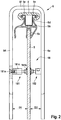
Figure 2 is a sectional view through the cover member and corresponding section of the handrail according tofigure 1 , -
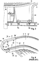
Figure 3 is an enlarged cross sectional view of a preferred attachment of the cover member offigure 1 to a landing cover plate, and -
Figure 4 is a perspective view of an elevator comprising a cover element according to the prior art. -
Figure 1 shows a perspective view of afirst landing area 1a of an escalator 1 according to a preferred embodiment of the invention. The arrows P1 depict the conveying direction of the escalator 1 so that thelanding area 1a shown is an entrance area. - The escalator 1 comprises two endless moving
handrails 4, astairway 2, comprisingsteps 2a and askirt 3, for eachhandrail 4. For purposes of easy reference,handrails 4, which each form an endless loop, are described as being respectively provided with afirst section 4a which is accessible to passengers, and travels in the conveying direction of the elevator, and a second section, which is inaccessible to passengers and travels in a direction opposed to the conveying direction. Part of this second section is shown infigure 3 and designated 4b. This second section travels withinskirt 3, which extends over the whole length of the escalator between the two landing areas. Between the first and the second sections, at each landing area of the elevator, aturnaround section 4c is provided for each handrail. Only onesuch turnaround section 4c per handrail is visible infigure 1 . Obviously, further turnaround sections (not shown) are provided at the opposing landing area of the escalator 1. Typical escalator features such as a comb in the transition area between landing area and steps are not explicitly shown in the figures. - The
skirts 3 are respectively adapted to hold abalustrade 5 at their respective lower sides. Thebalustrades 5 also extend along the whole length of the escalator. The rounded end sections ofbalustrade 5 are referred to a newel, designated 5a in the figures.Balustrades 5 serve to guide thehandrails 4 infirst section 4a. As can be seen infigure 1 andfigure 2 , the handrail is adapted to move along the upper sides ofrespective balustrades 5. In order to provide such a movement of thehandrail 4 along thebalustrade 5 in a safe manner with low friction, the upper side of thebalustrade 5 is provided with aholding mechanism 5b, which, in a preferred embodiment, straddles the upper side of thebalustrade 5 with its lower and 5c, and comprises anupper member 5d defining agliding surface 5e forhandrail 4. - As can be seen in
figure 1 andfigure 2 , acover member 6 is provided, which covers or straddleshandrail 4 inturnaround section 4c.Cover member 6 comprises afirst side wall 6d, asecond side wall 6e and atop section 6f connecting the two side walls. Be it noted that infigure 1 only onehandrail 4 is shown with such acover member 6. In practice, usually bothhandrails 4 will be provided with such acover member 6. However, it is also possible to provide only onehandrail 4 with such acover member 6, for example if dangers or hazards are only present on one side of the escalator. -
Cover member 6 comprises acover section 61 which essentially follows the curvature ofhandrail 4 in theturnaround section 4c. It is also provided with anattachment section 62, at which it is fixedly attached to static components of the escalator, as will be described in the following. -
Attachment section 62, which advantageously is integrally formed with thecover section 61, can be attached to alanding cover plate 15, as especially shown infigure 3 . Infigure 3 , theattachment section 62 ofcover member 6 is shown in more detail. Also, part of thesecond section 4b and ofturnaround section 4c ofhandrail 4 is shown. Here, theattachment section 62 is fixedly connected to alanding cover plate 15 of the escalator. For fixation, a number of bolts orscrews attachment section 62 and landingcover plate 15 are utilized. - As can be seen from
figures 1 and2 ,cover member 6 is provided with apositioning mechanism 18, which provide stabilization ofcover member 6 relative tobalustrade 5 by engagingside walls positioning mechanism 18 is provided such that respective distances D1, D2 between theside walls cover member 6 and thebalustrade 5 can be adjusted and secured in the set position. Thepositioning mechanism 18 comprises afirst screw mechanism 181, provided betweenside wall 6d andbalustrade 5, and asecond screw mechanism 182 betweenside wall 6e andbalustrade 5. For ease of reference, the individual components of the screw mechanism will only be described forfirst screw mechanism 181 in the following. Each screw mechanism comprises ascrew 181a, comprising a threading, extending through a hole inside wall side wall support element 181b engaging thebalustrade 5.Support element 181b comprises a threading on its circumference. Between there is provided anintermediate bushing 181c adapted to be threadingly engaged byscrew 181a andsupport element 181b. By turningscrew 181a and/orsupport element 181b relative tobushing 181c, the distance betweenside wall balustrade 5 can be adjusted and set. - Reference is now made to
figure 4 . Althoughfigure 4 shows an escalator according to the prior art, one advantageous feature, which is also applicable to the transport device according to the present invention shall now be briefly explained with reference tofigure 4 . -
Figure 4 shows a cover member 6' of an escalator according to the prior art. Here, anupper landing area 1b' is shown, from which the conveying direction of the elevator is downward to wards a lower landing (not shown infigure 4 ), as indicated by the arrow P2. Corresponding components of the escalator are designated with the same reference numerals as in the previous figures (with hyphons added), so that a description of these components and their functions will be omitted. - The main difference between this prior art elevator and the embodiment of the previous figures according to the invention lies in the attachment of
cover element 6 relative to static components of the escalator. According to this prior art escalator, thelower end 6f ofcover member 6 is attached to anewel end cap 20 which forms the end cap of and is attached toskirt member 3. It could additionally or alternatively be attached to aside panel 3a or atop panel 3b ofskirt 3. - Furthermore, along its extension between said
lower end 6f and anupper end 6g, i.e. inturnaround section 4c, the cover member is attached tobalustrade 5 by means of a number ofbrackets 24. Such brackets as used in the prior art require the provision of holes in the balustrade, which interact with screws or bolts for securing the brackets and thus the cover member to the balustrade. Especially retrofitting an escalator with such a cover member is cumbersome and requires a substantial amount of skilled work, including providing bore holes in the balustrade. According to the invention, as positioning a cover member relative to a balustrade only requires setting the adjustment mechanism without in any way damaging the balustrade, such retrofitting work is significantly reduced. - According to the embodiment shown in
figure 4 , theupper end 6g ofcover member 6 is positioned essentially or exactly vertically above the position at which movingsteps 2a ofstairway 2 emerge from undercover plate member 15, for example in a comb area (not specifically shown), as indicted by dashed line L. This dimensioning ofcover member 6 especially ensures that a passenger approaching escalator 1 can position himself on cover plate member 15 (which does not move), and at the same time stabilize himself by graspingcover member 6, which is also static. By simultaneously stepping on astep 2a and graspinghandrail 4, a safe transition from the static landing to the moveable steps of the escalator can be accomplished. As mentioned, this dimensioning of the cover member is advantageously also applicable for the embodiment of the invention shown infigures 1 to 3 . - Be it noted that the components for fixedly attaching the
cover member 6 to static components of the escalator as described in connection with the first embodiment offigures 1 to 3 and of the prior art escalator offigure 4 may also be combined, at least in part.
Claims (15)
- Transport device, especially escalator or moving walk, for conveying passengers between a first landing area and a second landing area in a conveying direction (P1,P2), with a skirt member and a balustrade (5), the balustrade comprising a lower and an upper side, the skirt member and the balustrade extending between the first landing area and the second landing area, the skirt member being adapted to secure the balustrade by engagement with its lower side, further comprising an endless moving handrail (4) forming a loop, a first section (4a) of which moves along the upper side of the balustrade in conveying direction (P1,P2),and a second section (4b) of which moves within the skirt member (3) in a direction opposed to the conveying direction, wherein two turnaround sections (4c) are provided between the first and the second sections (4a, 4b) in the vicinity of the first landing area and of the second landing area respectively, wherein at least one of the turnaround sections (4c) is provided with a cover member (6) adapted to render at least a part of the turnaround section (4c) of handrail (4) inaccessible to passengers, the cover member (6) comprising a positioning mechanism configured and adapted to position the cover member relative to the balustrade (5) in an adjustable manner.
- Transport device according to claim 1, wherein the positioning mechanism comprises at least one adjustable screw mechanism (181) configured and adapted to adjust a distance and/or an orientation of the cover member (6) relative to the balustrade (5).
- Transport device according to claim 2, wherein the screw mechanism (181) comprises a screw (181a) engaging a side wall (6d) of the cover member, an intermediate threaded or double threaded bushing (181c) and a support element (181b) engaging the balustrade, wherein the screw (181a) and the support element (181b) are adapted to threadingly engage the intermediate bushing (181c) such that the distance and/or orientation of cover member relative to balustrade can be adjustably set.
- Transport device according to any one of the preceding claims, wherein the positioning mechanism comprises a first screw mechanism (181) interacting with a first side surface of the balustrade and a second screw mechanism (182) interacting with a second side surface of the balustrade.
- Transport device according to any one of the preceding claims, wherein the cover member (6) extends between a newel end cap (20) of the balustrade and a point essentially vertically above a starting point of moving steps (2a) of the transport device.
- Transport device according to any one of the preceding claims, wherein the cover member (6) is fixedly attached to the skirt member (3) and/or a landing cover plate (15) of the transport device.
- Transport device according to any one of the preceding claims, wherein the cover member (6) is made of a plastics or polycarbonate material, which is preferably reinforced with fibres.
- Transport device according to any one of the preceding claims further comprising an anti-entrapment safety device adapted to cooperate with cover member (6).
- Transport device according to any one of the preceding claims, further comprising a deactivation system adapted to deactivate the transport device in case a passenger enters it in a direction opposed to transportation direction.
- Cover member for a handrail of a transport device, especially of an escalator or a moving walk, comprising a positioning mechanism configured and adapted to position the cover member relative to a balustrade (5) of the transport device in an adjustable manner.
- Cover member according to claim 10, wherein the positioning mechanism comprises at least one adjustable screw mechanism configured and adapted to adjust a distance and/or an orientation of the cover member relative to the balustrade (5).
- Cover member according to claim 10, wherein the screw mechanism comprises a screw engaging a side wall of the cover member, an intermediate threaded or double threaded bushing and a support element engaging the balustrade, wherein the screw and the support element are adapted to threadingly engage the intermediate bushing such that the distance and/or orientation of cover member relative to balustrade can be set.
- Cover member according to any one of the preceding claims 10 or 11, wherein the positioning mechanism comprises a first screw mechanism engaging a first side surface of the balustrade and a second screw mechanism engaging a second side surface of the balustrade.
- Method for backfitting a transport device, especially an escalator or moving walk, with a cover member (6) for a handrail, comprising the following steps: providing a cover member according to any one of claims 10-12 over a handrail provided on a balustrade of the transport device, adjusting the position of the cover member by means of positioning mechanism (18) relative to the balustrade such that the cover member has a desired position comprising desired distance and/or orientation relative to the balustrade, fixing the cover member in the desired position.
- Method according to claim 13, further comprising fixing the cover member (6) to a skirt member (3) and/or a landing cover plate (15) of the transport device.
Priority Applications (4)
| Application Number | Priority Date | Filing Date | Title |
|---|---|---|---|
| ES17380018T ES2952423T3 (en) | 2017-08-21 | 2017-08-21 | Transport device |
| EP17380018.6A EP3447021B1 (en) | 2017-08-21 | 2017-08-21 | Transport device |
| CN201810943409.5A CN109422189A (en) | 2017-08-21 | 2018-08-17 | Transport device |
| US16/105,131 US10597261B2 (en) | 2017-08-21 | 2018-08-20 | Transport device |
Applications Claiming Priority (1)
| Application Number | Priority Date | Filing Date | Title |
|---|---|---|---|
| EP17380018.6A EP3447021B1 (en) | 2017-08-21 | 2017-08-21 | Transport device |
Publications (2)
| Publication Number | Publication Date |
|---|---|
| EP3447021A1 true EP3447021A1 (en) | 2019-02-27 |
| EP3447021B1 EP3447021B1 (en) | 2023-05-24 |
Family
ID=59858669
Family Applications (1)
| Application Number | Title | Priority Date | Filing Date |
|---|---|---|---|
| EP17380018.6A Active EP3447021B1 (en) | 2017-08-21 | 2017-08-21 | Transport device |
Country Status (4)
| Country | Link |
|---|---|
| US (1) | US10597261B2 (en) |
| EP (1) | EP3447021B1 (en) |
| CN (1) | CN109422189A (en) |
| ES (1) | ES2952423T3 (en) |
Families Citing this family (3)
| Publication number | Priority date | Publication date | Assignee | Title |
|---|---|---|---|---|
| BR112022016845A2 (en) * | 2020-02-28 | 2022-10-11 | Inventio Ag | PERSON TRANSPORT INSTALLATION AND METHOD FOR PERSON TRANSPORT INSTALLATION OPERATION |
| USD951566S1 (en) * | 2020-08-21 | 2022-05-10 | Roger William Hickey | Escalator sanitizer |
| JP7307903B1 (en) | 2022-05-17 | 2023-07-13 | フジテック株式会社 | Man conveyor balustrade device, ultraviolet irradiation device and man conveyor |
Citations (5)
| Publication number | Priority date | Publication date | Assignee | Title |
|---|---|---|---|---|
| JPS58192871U (en) * | 1982-06-16 | 1983-12-22 | 三菱電機株式会社 | passenger conveyor safety device |
| US5366060A (en) * | 1993-10-07 | 1994-11-22 | Johnson Gerald E | Balustrade handrail entry housing |
| WO2006099829A1 (en) * | 2005-03-19 | 2006-09-28 | Kone Corporation | Balustrade head of an escalator or of a moving walkway |
| US7854313B1 (en) * | 2010-03-12 | 2010-12-21 | Jonathan Gotsche | Escalator handrail sanitizer |
| CN206088722U (en) * | 2016-10-19 | 2017-04-12 | 四川西子孚朗电梯有限公司 | Automatic staircase handrail lag |
Family Cites Families (11)
| Publication number | Priority date | Publication date | Assignee | Title |
|---|---|---|---|---|
| US2550918A (en) * | 1946-09-27 | 1951-05-01 | Sears Roebuck & Co | Escalator rail guard |
| US3941241A (en) * | 1974-04-02 | 1976-03-02 | Kinue Hishitani | Device for cleaning moving balustrade belt |
| FR2368309A1 (en) * | 1976-10-19 | 1978-05-19 | Leroger Nicole | Escalator hand-rail cleaning appts. - has housing containing impregnated pad pressed continuously against hand-rail by spring |
| DE10327312A1 (en) * | 2003-06-16 | 2005-01-05 | Dgth Druckgusstechnik Heiligenhaus Gmbh | Spacer for adjusting distance between wall and construction member, has positioning sleeve rotated to alter the length of the spacer as well as the distance separating the wall and the construction component |
| BR0318468B1 (en) * | 2003-08-20 | 2013-03-05 | protection device for escalator handrail. | |
| WO2006059364A1 (en) * | 2004-11-30 | 2006-06-08 | Mitsubishi Denki Kabushiki Kaisha | Device and method for repairing moving handrail of passenger conveyor |
| JP2008179481A (en) * | 2006-12-29 | 2008-08-07 | Thyssenkrupp Norte Sa | Safety device for moving handrail |
| ES2299408B1 (en) | 2007-10-18 | 2009-06-12 | Thyssenkrupp Elevator (Es/Pbb) Ltd. | SELF-SUPPORTING GUIDE SYSTEM FOR ROLLING CORRIDORS. |
| US10160622B2 (en) * | 2015-03-19 | 2018-12-25 | Sookyoung A.I.D. Co., Ltd. | Self-powered handrail sterilizing device and information collecting device using handrail sterilizing device |
| CN205274997U (en) * | 2015-12-31 | 2016-06-01 | 谢伯京 | Automatic protection device of staircase entry handrail |
| CN205312855U (en) * | 2016-01-28 | 2016-06-15 | 重庆交通大学 | Automatic handrail area safety device of staircase |
-
2017
- 2017-08-21 EP EP17380018.6A patent/EP3447021B1/en active Active
- 2017-08-21 ES ES17380018T patent/ES2952423T3/en active Active
-
2018
- 2018-08-17 CN CN201810943409.5A patent/CN109422189A/en active Pending
- 2018-08-20 US US16/105,131 patent/US10597261B2/en active Active
Patent Citations (5)
| Publication number | Priority date | Publication date | Assignee | Title |
|---|---|---|---|---|
| JPS58192871U (en) * | 1982-06-16 | 1983-12-22 | 三菱電機株式会社 | passenger conveyor safety device |
| US5366060A (en) * | 1993-10-07 | 1994-11-22 | Johnson Gerald E | Balustrade handrail entry housing |
| WO2006099829A1 (en) * | 2005-03-19 | 2006-09-28 | Kone Corporation | Balustrade head of an escalator or of a moving walkway |
| US7854313B1 (en) * | 2010-03-12 | 2010-12-21 | Jonathan Gotsche | Escalator handrail sanitizer |
| CN206088722U (en) * | 2016-10-19 | 2017-04-12 | 四川西子孚朗电梯有限公司 | Automatic staircase handrail lag |
Also Published As
| Publication number | Publication date |
|---|---|
| EP3447021B1 (en) | 2023-05-24 |
| CN109422189A (en) | 2019-03-05 |
| ES2952423T3 (en) | 2023-10-31 |
| US20190055110A1 (en) | 2019-02-21 |
| US10597261B2 (en) | 2020-03-24 |
Similar Documents
| Publication | Publication Date | Title |
|---|---|---|
| EP3447021A1 (en) | Transport device | |
| CN104030144A (en) | Passenger conveyor | |
| KR100951521B1 (en) | Traffic flow indicator on passenger conveyor | |
| JP5654569B2 (en) | Balustrade assembly for passenger conveyor | |
| HK1262326A1 (en) | Transport device | |
| US11220829B2 (en) | System for the safety of workers installing escalators | |
| US20190010709A1 (en) | Extendable rail system for heliports | |
| JP2008013290A (en) | Passenger conveyor | |
| TW200301217A (en) | Passenger conveyer device | |
| KR101576542B1 (en) | The safety handrail to easy installation | |
| KR101844397B1 (en) | Hand lift for inclined road walking | |
| EP3533746B1 (en) | Passenger conveying device having an antipinch structure | |
| CN100383031C (en) | Passenger Conveyor | |
| JP3435382B2 (en) | Stairway aisle equipment | |
| JP4410339B2 (en) | Passenger conveyor installation method | |
| JP5280017B2 (en) | Escalator device | |
| JP3595717B2 (en) | Passage equipment | |
| CN107826954B (en) | Anti-pinch device for escalator with guiding function | |
| US20220034095A1 (en) | Extendable rail system for heliports | |
| CN215479114U (en) | Escalator foundation pit cover plate with buckles | |
| WO2015119532A1 (en) | Elevating device | |
| JPH11159094A (en) | Staircase | |
| JP2006062812A (en) | Inlet safety device for man-conveyor | |
| JPH04286594A (en) | passenger conveyor railing | |
| KR200206393Y1 (en) | Apparatus for safety of escalator passenger |
Legal Events
| Date | Code | Title | Description |
|---|---|---|---|
| PUAI | Public reference made under article 153(3) epc to a published international application that has entered the european phase |
Free format text: ORIGINAL CODE: 0009012 |
|
| STAA | Information on the status of an ep patent application or granted ep patent |
Free format text: STATUS: THE APPLICATION HAS BEEN PUBLISHED |
|
| AK | Designated contracting states |
Kind code of ref document: A1 Designated state(s): AL AT BE BG CH CY CZ DE DK EE ES FI FR GB GR HR HU IE IS IT LI LT LU LV MC MK MT NL NO PL PT RO RS SE SI SK SM TR |
|
| AX | Request for extension of the european patent |
Extension state: BA ME |
|
| STAA | Information on the status of an ep patent application or granted ep patent |
Free format text: STATUS: REQUEST FOR EXAMINATION WAS MADE |
|
| 17P | Request for examination filed |
Effective date: 20190827 |
|
| RBV | Designated contracting states (corrected) |
Designated state(s): AL AT BE BG CH CY CZ DE DK EE ES FI FR GB GR HR HU IE IS IT LI LT LU LV MC MK MT NL NO PL PT RO RS SE SI SK SM TR |
|
| STAA | Information on the status of an ep patent application or granted ep patent |
Free format text: STATUS: EXAMINATION IS IN PROGRESS |
|
| RAP1 | Party data changed (applicant data changed or rights of an application transferred) |
Owner name: THYSSENKRUPP ELEVATOR INNOVATION CENTER, S.A. |
|
| 17Q | First examination report despatched |
Effective date: 20200512 |
|
| RAP3 | Party data changed (applicant data changed or rights of an application transferred) |
Owner name: TK ELEVATOR INNOVATION CENTER S.A. |
|
| RAP1 | Party data changed (applicant data changed or rights of an application transferred) |
Owner name: TK ESCALATOR NORTE, S.A. |
|
| GRAP | Despatch of communication of intention to grant a patent |
Free format text: ORIGINAL CODE: EPIDOSNIGR1 |
|
| STAA | Information on the status of an ep patent application or granted ep patent |
Free format text: STATUS: GRANT OF PATENT IS INTENDED |
|
| INTG | Intention to grant announced |
Effective date: 20221207 |
|
| GRAS | Grant fee paid |
Free format text: ORIGINAL CODE: EPIDOSNIGR3 |
|
| GRAA | (expected) grant |
Free format text: ORIGINAL CODE: 0009210 |
|
| STAA | Information on the status of an ep patent application or granted ep patent |
Free format text: STATUS: THE PATENT HAS BEEN GRANTED |
|
| AK | Designated contracting states |
Kind code of ref document: B1 Designated state(s): AL AT BE BG CH CY CZ DE DK EE ES FI FR GB GR HR HU IE IS IT LI LT LU LV MC MK MT NL NO PL PT RO RS SE SI SK SM TR |
|
| REG | Reference to a national code |
Ref country code: GB Ref legal event code: FG4D |
|
| REG | Reference to a national code |
Ref country code: CH Ref legal event code: EP |
|
| REG | Reference to a national code |
Ref country code: DE Ref legal event code: R096 Ref document number: 602017068968 Country of ref document: DE |
|
| REG | Reference to a national code |
Ref country code: AT Ref legal event code: REF Ref document number: 1569404 Country of ref document: AT Kind code of ref document: T Effective date: 20230615 |
|
| REG | Reference to a national code |
Ref country code: IE Ref legal event code: FG4D |
|
| P01 | Opt-out of the competence of the unified patent court (upc) registered |
Effective date: 20230614 |
|
| REG | Reference to a national code |
Ref country code: LT Ref legal event code: MG9D |
|
| REG | Reference to a national code |
Ref country code: NL Ref legal event code: MP Effective date: 20230524 |
|
| REG | Reference to a national code |
Ref country code: AT Ref legal event code: MK05 Ref document number: 1569404 Country of ref document: AT Kind code of ref document: T Effective date: 20230524 |
|
| PG25 | Lapsed in a contracting state [announced via postgrant information from national office to epo] |
Ref country code: SE Free format text: LAPSE BECAUSE OF FAILURE TO SUBMIT A TRANSLATION OF THE DESCRIPTION OR TO PAY THE FEE WITHIN THE PRESCRIBED TIME-LIMIT Effective date: 20230524 Ref country code: PT Free format text: LAPSE BECAUSE OF FAILURE TO SUBMIT A TRANSLATION OF THE DESCRIPTION OR TO PAY THE FEE WITHIN THE PRESCRIBED TIME-LIMIT Effective date: 20230925 Ref country code: NO Free format text: LAPSE BECAUSE OF FAILURE TO SUBMIT A TRANSLATION OF THE DESCRIPTION OR TO PAY THE FEE WITHIN THE PRESCRIBED TIME-LIMIT Effective date: 20230824 Ref country code: NL Free format text: LAPSE BECAUSE OF FAILURE TO SUBMIT A TRANSLATION OF THE DESCRIPTION OR TO PAY THE FEE WITHIN THE PRESCRIBED TIME-LIMIT Effective date: 20230524 Ref country code: AT Free format text: LAPSE BECAUSE OF FAILURE TO SUBMIT A TRANSLATION OF THE DESCRIPTION OR TO PAY THE FEE WITHIN THE PRESCRIBED TIME-LIMIT Effective date: 20230524 |
|
| REG | Reference to a national code |
Ref country code: ES Ref legal event code: FG2A Ref document number: 2952423 Country of ref document: ES Kind code of ref document: T3 Effective date: 20231031 |
|
| PG25 | Lapsed in a contracting state [announced via postgrant information from national office to epo] |
Ref country code: RS Free format text: LAPSE BECAUSE OF FAILURE TO SUBMIT A TRANSLATION OF THE DESCRIPTION OR TO PAY THE FEE WITHIN THE PRESCRIBED TIME-LIMIT Effective date: 20230524 Ref country code: PL Free format text: LAPSE BECAUSE OF FAILURE TO SUBMIT A TRANSLATION OF THE DESCRIPTION OR TO PAY THE FEE WITHIN THE PRESCRIBED TIME-LIMIT Effective date: 20230524 Ref country code: LV Free format text: LAPSE BECAUSE OF FAILURE TO SUBMIT A TRANSLATION OF THE DESCRIPTION OR TO PAY THE FEE WITHIN THE PRESCRIBED TIME-LIMIT Effective date: 20230524 Ref country code: LT Free format text: LAPSE BECAUSE OF FAILURE TO SUBMIT A TRANSLATION OF THE DESCRIPTION OR TO PAY THE FEE WITHIN THE PRESCRIBED TIME-LIMIT Effective date: 20230524 Ref country code: IS Free format text: LAPSE BECAUSE OF FAILURE TO SUBMIT A TRANSLATION OF THE DESCRIPTION OR TO PAY THE FEE WITHIN THE PRESCRIBED TIME-LIMIT Effective date: 20230924 Ref country code: HR Free format text: LAPSE BECAUSE OF FAILURE TO SUBMIT A TRANSLATION OF THE DESCRIPTION OR TO PAY THE FEE WITHIN THE PRESCRIBED TIME-LIMIT Effective date: 20230524 |
|
| PG25 | Lapsed in a contracting state [announced via postgrant information from national office to epo] |
Ref country code: FI Free format text: LAPSE BECAUSE OF FAILURE TO SUBMIT A TRANSLATION OF THE DESCRIPTION OR TO PAY THE FEE WITHIN THE PRESCRIBED TIME-LIMIT Effective date: 20230524 |
|
| PG25 | Lapsed in a contracting state [announced via postgrant information from national office to epo] |
Ref country code: SK Free format text: LAPSE BECAUSE OF FAILURE TO SUBMIT A TRANSLATION OF THE DESCRIPTION OR TO PAY THE FEE WITHIN THE PRESCRIBED TIME-LIMIT Effective date: 20230524 |
|
| PG25 | Lapsed in a contracting state [announced via postgrant information from national office to epo] |
Ref country code: SM Free format text: LAPSE BECAUSE OF FAILURE TO SUBMIT A TRANSLATION OF THE DESCRIPTION OR TO PAY THE FEE WITHIN THE PRESCRIBED TIME-LIMIT Effective date: 20230524 Ref country code: SK Free format text: LAPSE BECAUSE OF FAILURE TO SUBMIT A TRANSLATION OF THE DESCRIPTION OR TO PAY THE FEE WITHIN THE PRESCRIBED TIME-LIMIT Effective date: 20230524 Ref country code: RO Free format text: LAPSE BECAUSE OF FAILURE TO SUBMIT A TRANSLATION OF THE DESCRIPTION OR TO PAY THE FEE WITHIN THE PRESCRIBED TIME-LIMIT Effective date: 20230524 Ref country code: EE Free format text: LAPSE BECAUSE OF FAILURE TO SUBMIT A TRANSLATION OF THE DESCRIPTION OR TO PAY THE FEE WITHIN THE PRESCRIBED TIME-LIMIT Effective date: 20230524 Ref country code: DK Free format text: LAPSE BECAUSE OF FAILURE TO SUBMIT A TRANSLATION OF THE DESCRIPTION OR TO PAY THE FEE WITHIN THE PRESCRIBED TIME-LIMIT Effective date: 20230524 Ref country code: CZ Free format text: LAPSE BECAUSE OF FAILURE TO SUBMIT A TRANSLATION OF THE DESCRIPTION OR TO PAY THE FEE WITHIN THE PRESCRIBED TIME-LIMIT Effective date: 20230524 |
|
| REG | Reference to a national code |
Ref country code: DE Ref legal event code: R097 Ref document number: 602017068968 Country of ref document: DE |
|
| PG25 | Lapsed in a contracting state [announced via postgrant information from national office to epo] |
Ref country code: MC Free format text: LAPSE BECAUSE OF FAILURE TO SUBMIT A TRANSLATION OF THE DESCRIPTION OR TO PAY THE FEE WITHIN THE PRESCRIBED TIME-LIMIT Effective date: 20230524 |
|
| REG | Reference to a national code |
Ref country code: CH Ref legal event code: PL |
|
| PG25 | Lapsed in a contracting state [announced via postgrant information from national office to epo] |
Ref country code: MC Free format text: LAPSE BECAUSE OF FAILURE TO SUBMIT A TRANSLATION OF THE DESCRIPTION OR TO PAY THE FEE WITHIN THE PRESCRIBED TIME-LIMIT Effective date: 20230524 |
|
| PLBE | No opposition filed within time limit |
Free format text: ORIGINAL CODE: 0009261 |
|
| STAA | Information on the status of an ep patent application or granted ep patent |
Free format text: STATUS: NO OPPOSITION FILED WITHIN TIME LIMIT |
|
| PG25 | Lapsed in a contracting state [announced via postgrant information from national office to epo] |
Ref country code: LU Free format text: LAPSE BECAUSE OF NON-PAYMENT OF DUE FEES Effective date: 20230821 |
|
| PG25 | Lapsed in a contracting state [announced via postgrant information from national office to epo] |
Ref country code: LU Free format text: LAPSE BECAUSE OF NON-PAYMENT OF DUE FEES Effective date: 20230821 Ref country code: CH Free format text: LAPSE BECAUSE OF NON-PAYMENT OF DUE FEES Effective date: 20230831 |
|
| 26N | No opposition filed |
Effective date: 20240227 |
|
| PG25 | Lapsed in a contracting state [announced via postgrant information from national office to epo] |
Ref country code: SI Free format text: LAPSE BECAUSE OF FAILURE TO SUBMIT A TRANSLATION OF THE DESCRIPTION OR TO PAY THE FEE WITHIN THE PRESCRIBED TIME-LIMIT Effective date: 20230524 |
|
| REG | Reference to a national code |
Ref country code: BE Ref legal event code: MM Effective date: 20230831 |
|
| REG | Reference to a national code |
Ref country code: IE Ref legal event code: MM4A |
|
| PG25 | Lapsed in a contracting state [announced via postgrant information from national office to epo] |
Ref country code: SI Free format text: LAPSE BECAUSE OF FAILURE TO SUBMIT A TRANSLATION OF THE DESCRIPTION OR TO PAY THE FEE WITHIN THE PRESCRIBED TIME-LIMIT Effective date: 20230524 Ref country code: IT Free format text: LAPSE BECAUSE OF FAILURE TO SUBMIT A TRANSLATION OF THE DESCRIPTION OR TO PAY THE FEE WITHIN THE PRESCRIBED TIME-LIMIT Effective date: 20230524 |
|
| PG25 | Lapsed in a contracting state [announced via postgrant information from national office to epo] |
Ref country code: IE Free format text: LAPSE BECAUSE OF NON-PAYMENT OF DUE FEES Effective date: 20230821 |
|
| PG25 | Lapsed in a contracting state [announced via postgrant information from national office to epo] |
Ref country code: IE Free format text: LAPSE BECAUSE OF NON-PAYMENT OF DUE FEES Effective date: 20230821 Ref country code: FR Free format text: LAPSE BECAUSE OF NON-PAYMENT OF DUE FEES Effective date: 20230831 |
|
| PG25 | Lapsed in a contracting state [announced via postgrant information from national office to epo] |
Ref country code: BE Free format text: LAPSE BECAUSE OF NON-PAYMENT OF DUE FEES Effective date: 20230831 |
|
| PG25 | Lapsed in a contracting state [announced via postgrant information from national office to epo] |
Ref country code: BG Free format text: LAPSE BECAUSE OF FAILURE TO SUBMIT A TRANSLATION OF THE DESCRIPTION OR TO PAY THE FEE WITHIN THE PRESCRIBED TIME-LIMIT Effective date: 20230524 |
|
| PG25 | Lapsed in a contracting state [announced via postgrant information from national office to epo] |
Ref country code: BG Free format text: LAPSE BECAUSE OF FAILURE TO SUBMIT A TRANSLATION OF THE DESCRIPTION OR TO PAY THE FEE WITHIN THE PRESCRIBED TIME-LIMIT Effective date: 20230524 |
|
| PG25 | Lapsed in a contracting state [announced via postgrant information from national office to epo] |
Ref country code: CY Free format text: LAPSE BECAUSE OF FAILURE TO SUBMIT A TRANSLATION OF THE DESCRIPTION OR TO PAY THE FEE WITHIN THE PRESCRIBED TIME-LIMIT; INVALID AB INITIO Effective date: 20170821 |
|
| PG25 | Lapsed in a contracting state [announced via postgrant information from national office to epo] |
Ref country code: HU Free format text: LAPSE BECAUSE OF FAILURE TO SUBMIT A TRANSLATION OF THE DESCRIPTION OR TO PAY THE FEE WITHIN THE PRESCRIBED TIME-LIMIT; INVALID AB INITIO Effective date: 20170821 |
|
| PG25 | Lapsed in a contracting state [announced via postgrant information from national office to epo] |
Ref country code: GR Free format text: LAPSE BECAUSE OF FAILURE TO SUBMIT A TRANSLATION OF THE DESCRIPTION OR TO PAY THE FEE WITHIN THE PRESCRIBED TIME-LIMIT; INVALID AB INITIO Effective date: 20170821 |
|
| PGFP | Annual fee paid to national office [announced via postgrant information from national office to epo] |
Ref country code: ES Payment date: 20250926 Year of fee payment: 9 |
|
| PGFP | Annual fee paid to national office [announced via postgrant information from national office to epo] |
Ref country code: DE Payment date: 20250820 Year of fee payment: 9 |
|
| PGFP | Annual fee paid to national office [announced via postgrant information from national office to epo] |
Ref country code: GB Payment date: 20250821 Year of fee payment: 9 |
|
| PG25 | Lapsed in a contracting state [announced via postgrant information from national office to epo] |
Ref country code: TR Free format text: LAPSE BECAUSE OF FAILURE TO SUBMIT A TRANSLATION OF THE DESCRIPTION OR TO PAY THE FEE WITHIN THE PRESCRIBED TIME-LIMIT Effective date: 20230524 |