EP3446951A1 - Working device on inclined surface and cleaning method applied in solar power station - Google Patents
Working device on inclined surface and cleaning method applied in solar power station Download PDFInfo
- Publication number
- EP3446951A1 EP3446951A1 EP18189863.6A EP18189863A EP3446951A1 EP 3446951 A1 EP3446951 A1 EP 3446951A1 EP 18189863 A EP18189863 A EP 18189863A EP 3446951 A1 EP3446951 A1 EP 3446951A1
- Authority
- EP
- European Patent Office
- Prior art keywords
- trailer
- cleaning
- solar panel
- inclined surface
- robot
- Prior art date
- Legal status (The legal status is an assumption and is not a legal conclusion. Google has not performed a legal analysis and makes no representation as to the accuracy of the status listed.)
- Granted
Links
Images


Classifications
-
- B—PERFORMING OPERATIONS; TRANSPORTING
- B08—CLEANING
- B08B—CLEANING IN GENERAL; PREVENTION OF FOULING IN GENERAL
- B08B1/00—Cleaning by methods involving the use of tools
-
- B—PERFORMING OPERATIONS; TRANSPORTING
- B08—CLEANING
- B08B—CLEANING IN GENERAL; PREVENTION OF FOULING IN GENERAL
- B08B1/00—Cleaning by methods involving the use of tools
- B08B1/10—Cleaning by methods involving the use of tools characterised by the type of cleaning tool
- B08B1/12—Brushes
-
- B—PERFORMING OPERATIONS; TRANSPORTING
- B08—CLEANING
- B08B—CLEANING IN GENERAL; PREVENTION OF FOULING IN GENERAL
- B08B1/00—Cleaning by methods involving the use of tools
- B08B1/30—Cleaning by methods involving the use of tools by movement of cleaning members over a surface
- B08B1/32—Cleaning by methods involving the use of tools by movement of cleaning members over a surface using rotary cleaning members
-
- B—PERFORMING OPERATIONS; TRANSPORTING
- B08—CLEANING
- B08B—CLEANING IN GENERAL; PREVENTION OF FOULING IN GENERAL
- B08B1/00—Cleaning by methods involving the use of tools
- B08B1/30—Cleaning by methods involving the use of tools by movement of cleaning members over a surface
- B08B1/32—Cleaning by methods involving the use of tools by movement of cleaning members over a surface using rotary cleaning members
- B08B1/34—Cleaning by methods involving the use of tools by movement of cleaning members over a surface using rotary cleaning members rotating about an axis parallel to the surface
-
- B—PERFORMING OPERATIONS; TRANSPORTING
- B08—CLEANING
- B08B—CLEANING IN GENERAL; PREVENTION OF FOULING IN GENERAL
- B08B13/00—Accessories or details of general applicability for machines or apparatus for cleaning
-
- B—PERFORMING OPERATIONS; TRANSPORTING
- B08—CLEANING
- B08B—CLEANING IN GENERAL; PREVENTION OF FOULING IN GENERAL
- B08B3/00—Cleaning by methods involving the use or presence of liquid or steam
-
- E—FIXED CONSTRUCTIONS
- E04—BUILDING
- E04G—SCAFFOLDING; FORMS; SHUTTERING; BUILDING IMPLEMENTS OR AIDS, OR THEIR USE; HANDLING BUILDING MATERIALS ON THE SITE; REPAIRING, BREAKING-UP OR OTHER WORK ON EXISTING BUILDINGS
- E04G23/00—Working measures on existing buildings
- E04G23/002—Arrangements for cleaning building facades
-
- F—MECHANICAL ENGINEERING; LIGHTING; HEATING; WEAPONS; BLASTING
- F24—HEATING; RANGES; VENTILATING
- F24S—SOLAR HEAT COLLECTORS; SOLAR HEAT SYSTEMS
- F24S40/00—Safety or protection arrangements of solar heat collectors; Preventing malfunction of solar heat collectors
- F24S40/20—Cleaning; Removing snow
-
- G—PHYSICS
- G05—CONTROLLING; REGULATING
- G05D—SYSTEMS FOR CONTROLLING OR REGULATING NON-ELECTRIC VARIABLES
- G05D1/00—Control of position, course, altitude or attitude of land, water, air or space vehicles, e.g. using automatic pilots
-
- G—PHYSICS
- G05—CONTROLLING; REGULATING
- G05D—SYSTEMS FOR CONTROLLING OR REGULATING NON-ELECTRIC VARIABLES
- G05D1/00—Control of position, course, altitude or attitude of land, water, air or space vehicles, e.g. using automatic pilots
- G05D1/02—Control of position or course in two dimensions
- G05D1/021—Control of position or course in two dimensions specially adapted to land vehicles
- G05D1/0212—Control of position or course in two dimensions specially adapted to land vehicles with means for defining a desired trajectory
- G05D1/0219—Control of position or course in two dimensions specially adapted to land vehicles with means for defining a desired trajectory ensuring the processing of the whole working surface
-
- G—PHYSICS
- G05—CONTROLLING; REGULATING
- G05D—SYSTEMS FOR CONTROLLING OR REGULATING NON-ELECTRIC VARIABLES
- G05D1/00—Control of position, course, altitude or attitude of land, water, air or space vehicles, e.g. using automatic pilots
- G05D1/02—Control of position or course in two dimensions
- G05D1/021—Control of position or course in two dimensions specially adapted to land vehicles
- G05D1/0231—Control of position or course in two dimensions specially adapted to land vehicles using optical position detecting means
-
- G—PHYSICS
- G05—CONTROLLING; REGULATING
- G05D—SYSTEMS FOR CONTROLLING OR REGULATING NON-ELECTRIC VARIABLES
- G05D1/00—Control of position, course, altitude or attitude of land, water, air or space vehicles, e.g. using automatic pilots
- G05D1/02—Control of position or course in two dimensions
- G05D1/021—Control of position or course in two dimensions specially adapted to land vehicles
- G05D1/0287—Control of position or course in two dimensions specially adapted to land vehicles involving a plurality of land vehicles, e.g. fleet or convoy travelling
-
- H—ELECTRICITY
- H02—GENERATION; CONVERSION OR DISTRIBUTION OF ELECTRIC POWER
- H02S—GENERATION OF ELECTRIC POWER BY CONVERSION OF INFRARED RADIATION, VISIBLE LIGHT OR ULTRAVIOLET LIGHT, e.g. USING PHOTOVOLTAIC [PV] MODULES
- H02S40/00—Components or accessories in combination with PV modules, not provided for in groups H02S10/00 - H02S30/00
- H02S40/10—Cleaning arrangements
-
- B—PERFORMING OPERATIONS; TRANSPORTING
- B08—CLEANING
- B08B—CLEANING IN GENERAL; PREVENTION OF FOULING IN GENERAL
- B08B3/00—Cleaning by methods involving the use or presence of liquid or steam
- B08B3/04—Cleaning involving contact with liquid
-
- Y—GENERAL TAGGING OF NEW TECHNOLOGICAL DEVELOPMENTS; GENERAL TAGGING OF CROSS-SECTIONAL TECHNOLOGIES SPANNING OVER SEVERAL SECTIONS OF THE IPC; TECHNICAL SUBJECTS COVERED BY FORMER USPC CROSS-REFERENCE ART COLLECTIONS [XRACs] AND DIGESTS
- Y02—TECHNOLOGIES OR APPLICATIONS FOR MITIGATION OR ADAPTATION AGAINST CLIMATE CHANGE
- Y02E—REDUCTION OF GREENHOUSE GAS [GHG] EMISSIONS, RELATED TO ENERGY GENERATION, TRANSMISSION OR DISTRIBUTION
- Y02E10/00—Energy generation through renewable energy sources
- Y02E10/40—Solar thermal energy, e.g. solar towers
-
- Y—GENERAL TAGGING OF NEW TECHNOLOGICAL DEVELOPMENTS; GENERAL TAGGING OF CROSS-SECTIONAL TECHNOLOGIES SPANNING OVER SEVERAL SECTIONS OF THE IPC; TECHNICAL SUBJECTS COVERED BY FORMER USPC CROSS-REFERENCE ART COLLECTIONS [XRACs] AND DIGESTS
- Y02—TECHNOLOGIES OR APPLICATIONS FOR MITIGATION OR ADAPTATION AGAINST CLIMATE CHANGE
- Y02E—REDUCTION OF GREENHOUSE GAS [GHG] EMISSIONS, RELATED TO ENERGY GENERATION, TRANSMISSION OR DISTRIBUTION
- Y02E10/00—Energy generation through renewable energy sources
- Y02E10/50—Photovoltaic [PV] energy
Definitions
- the invention herein refers to the working robot working on inclined surfaces, which can be applied to the solar power stations, in particular to the inclined surfaces, as well as the cleaning method thereof applied in a solar power station.
- the solar panel is exposed to the air, where the dust falls on the components and blocks the sunlight, which will seriously affect the solar panel conversion efficiency.
- the uneven illumination may cause local overheating to generate hot spots, thereby destroying the solar panel.
- the operation process is as follows. First, two or more workers are required to mount the robot on the solar panel arrays. After installation, the robot begins to move laterally along the solar panel arrays, and the cleaning unit on the robot moves up and down along the path, thereby cleaning the solar panel arrays. After cleaning one solar panel array, two or more workers are needed to take the robot down and install it on another solar panel array.
- the problem with this cleaning method is:
- the technicians propose a further solution, which is a rail-mounted robot installed on each solar panel array.
- the robot works in the same way as the robot described above.
- the difference is that a rail-mounted robot is installed on a solar panel array for a long time and only needs to be installed once, which enables frequent and efficient cleaning and ensures that the solar panels are always clean. It can significantly increase power generation efficiency.
- the number of arrays of solar power stations is hundreds of thousands. If one robot is installed on each array, thousands of robots are needed. A large number of robots are distributed in the solar power station covering thousands of acres, which will not only lead to challenging pre-installation work and high investment, but also bring about demanding management and maintenance work.
- the technical problem to be solved by the present invention is to provide a working device and a method thereof on an inclined surface, for example, a cleaning device for a solar power station and a cleaning method thereof, which features low investment, easy installation and removal, operator-friendly management and maintenance.
- the invention mentioned herein refers to a working device for the inclined surface, consisting of a working robot and a trailer that runs on an inclined surface, and a cable connecting the working robot and the trailer.
- the working robot and the trailer are equipped with the positioning system detecting their relative positions, so the trailer can recognize the position of the working robot and follow the working robot autonomously.
- the trailer is equipped with a power supply to supply continuous power to the working robot via the cable.
- the invention mentioned herein serves as a cleaning device for the solar power station with solar panel arrays comprising one or more solar panels.
- the cleaning device of the solar power station comprises a cleaning robot and a trailer for cleaning each solar panel array, as well as a cable between the cleaning robot and the trailer, which share their positions mutually via the positioning system.
- the trailer is capable of recognizing the position of the cleaning robot and performing autonomous movement following the cleaning robot.
- the trailer is equipped with a power supply to supply continuous power to the cleaning robot via the cable.
- an orientation sensor and an edge detection sensor are provided on the cleaning robot to enable autonomous movement on the solar panel array along the predetermined cleaning path; a signal indicator is designed on the cleaning robot, which issues the signal after the cleaning is completed.
- a conduit is included in the cable between the cleaning robot and the trailer, and a raw material box is provided on the trailer.
- the cleaning materials such as water, cleaning agent, etc, are provided to the cleaning robot.
- the trailer consists of a frame and the detachable parts, including a battery, and/or a controller, and/or a raw material box.
- an edge detection device capable of detecting the edge of the inclined surface is provided on the trailer.
- the inclined surface refers to an inclined surface of the solar panel arrays
- the edge detection device on the trailer is capable of detecting the edge of the solar panel array.
- the edge detection device is compose of two object sensing sets.
- each object sensing set consists of two object sensing cells.
- the camera and the image processing system are mounted on the trailer, of which the camera captures the image of the inclined surface and the edge thereof.
- the captured image is transmitted to the image processing system in real time for analysis and processing, and the pixel coordinates of the lower edge in the image are used to determine the position and direction of the trailer relative to the lower edge of the inclined surface.
- the position and direction of the trailer are adjusted accordingly to ensure that the trailer moves generally along the lower edge of the inclined surface.
- the invention mentioned herein also provides a cleaning method for the solar power station with one or more solar panel arrays comprising multiple solar panel, of which the inclined surface as described above can be cleaned with the working device mentioned above.
- the inclined surface refers to the surface of the solar panel array.
- the operation mentioned herein refers to the cleaning work, and the working robot refers to the cleaning robot.
- the cleaning work involves the following steps:
- the invention mentioned herein also provides a cleaning method for the solar power station with one or more solar panel arrays comprising multiple solar panels, of which the inclined surface as described above can be cleaned with the working device mentioned above.
- the inclined surface refers to the surface of the solar panel array.
- the operation mentioned herein refers to the cleaning work, and the working robot refers to the cleaning robot.
- the cleaning work involves the following steps:
- the working device for the inclined surface mentioned herein and the cleaning method thereof applied to the solar power station have the following characteristics:
- the invention mentioned herein refers to a working device for working on the inclined surface, consisting of a working robot and a trailer that runs on an inclined surface, and a cable connecting the working robot and the trailer.
- the working robot and the trailer detect the relative positions via the positioning system, so the trailer can recognize the position of the working robot and follow the working robot autonomously.
- the trailer is equipped with a power supply to supply continuous power to the working robot via the cable.
- the example of the invention for cleaning solar power stations is shown in Figure 1 .
- the solar power station consists of one or more solar panel arrays A, which are composed of one or more solar panels.
- the surface of the solar panel array A is inclined toward the direction of the sun.
- the cleaning device of the solar power station consists of a cleaning robot 1 and a trailer 2 that are cleaning each solar panel array, as well as a cable 3 connecting the cleaning robot 1 and the trailer 2.
- the positioning system is composed of a wireless distance-measuring unit 4. Two wireless distance-measuring units 4 are provided on the trailer 2. A wireless distance-measuring unit 5 is provided on the cleaning robot 1. The wireless distance-measuring units can communicate with each other and detect the distance between each other. Thus, the trailer 2 can recognize the position of the cleaning robot 1 and follow the cleaning robot 1 for autonomous movement.
- An orientation sensor is mounted on the trailer 2, of which the signal is used to maintain its linear motion.
- the cleaning tools such as rotating brushes, are provided on the front and rear sides of the cleaning robot 1 respectively.
- the power supply is equipped on the trailer 2, which supplies the continuous power for the cleaning work of the cleaning robot 1 via the cable 3.
- the trailer 2 is loaded with a large-capacity battery, and the cleaning robot 1 is continuously powered via the cable 3.
- An orientation senor and an edge detecting sensor are provided on the cleaning robot 1. With the signal from the orientation senor, the cleaning robot 1 can maintain its direction of motion; with the signal from the edge detecting sensor, the cleaning robot 1 can judge the edge of the solar panel array A.
- the cleaning robot 1 can autonomously move on the solar panel array A according to a predetermined cleaning path (dashed line in Figure 3 ) and ensure that it does not fall off the solar panel array.
- a predetermined cleaning path dashed line in Figure 3
- the edge detecting sensor of the cleaning robot 1 is triggered by the edge of the solar panel array A multiple times in a short time, and the cleaning is thought to have completed.
- a signal indicator is provided on the cleaning robot 1 to issue a prompt signal.
- a conduit is included in the cable 3 connecting the cleaning robot 1 and the trailer 2.
- a raw material box is provided on the trailer, and the cleaning materials, such as water are cleaning agent, are supplied to the cleaning robot.
- the volume and weight of the trailer 2 are designed as small as possible. If the trailer 2 is designed to be small (For example, it is assembled with small wheels, compact body and small power motor), the trailer 2's traveling ability, obstacle performance and driving performance will be affected. Solar power stations are usually built in deserts and farmland, where the ground is uneven and there will be a large number of pits and bulges. Moving on such a ground puts high requirements for the trailer 2 on overcoming obstacles and driving performance. Obviously, the higher the frame of the trailer 2, the larger the wheel, the greater the driving power and the better the traveling ability on the complex ground surface, but the weight and volume of the frame will also become larger, which is not conducive to daily maintenance. For example, a worker needs to recover the trailer 2 and charge it every day. If the trailer 2 becomes bigger and heavier, it will be very difficult for the workers.
- the trailer 2 is designed in a split manner as shown in Figure 2 .
- the trailer 2 is composed of a frame 6 and a detachable part 7.
- the detachable part 7 consists of a battery, and/or a controller, and/or a raw material box.
- the frame 6 can be designed to be tall, large and heavy according to the road conditions, which is placed in the solar power station for a long time.
- the detachable part 7 requires scheduled maintenance, special maintenance and protection (For example, the battery pack, the control circuit board and the raw material box). Taking daily battery charging as an example, the worker only needs to take off the detachable part of the battery pack and take it back to the charging center, which greatly reduces the labor intensity of the worker.
- the trailer can maintain the direction of linear motion along the solar panel arrays.
- This method has the following problems, which may cause the trailer to collide with the solar panel arrays.
- An edge detection device is mounted on the trailer 2, which can detect the edge of the solar panel array A. It is fixed to the trailer 2 via a sensor holder 8. With the help of the edge detection device, the trailer knows its relative position to the solar panel arrays so that it can move smoothly along the solar panel arrays.
- the edge detection device consists of two object sensing sets, and each object sensing set are composed of two object sensing cells installed at high and low positions.
- the edge detection device consists of four object sensing cells, which are divided into two sets, two in each set, respectively mounted on the sensor holders 8 on both sides of the trailer 2, labeled G1, G2, G3 and G4.
- the partially enlarged schematic view showing the relative position between the object sensing cells and the edge of the solar panel array A is shown in Figure 5 .
- the object sensing cell at the higher position is located directly above the inclined surface, which can detect the inclined surface, and the object sensing cell at the lower position is located beyond the inclined surface, which cannot detect the inclined surface.
- the object sensing cells are respectively located on the upper and lower sides of the edge of the solar panel array A.
- One object sensing cell can detect the solar panel, and the other object sensing cell cannot detect the solar panel.
- the relative position between the trailer 2 and the solar panel array A can be known by checking the status of the four object sensing cells.
- the direction and moving path of the trailer 2 can be adjusted such that it can always move along the solar panel array A, of which edge serves as the reference. For example, when G1 and G3 sense the solar panel, but G2 and G4 do not detect the solar panel, then the trailer 2 maintains a desirable position from the edge of the solar panel array A; when only G1 senses the solar panel, but G3, G2 and G4 do not perceive the solar panel, it indicates that the trailer 2 has been seriously skewed relative to the edge of the solar panel array A.
- the direction of the trailer 2 shall be adjusted in time to help the trailer 2 to resume the desirable relative position with the edge of the solar panel array A.
- the edge detection device is installed on the trailer 2, a closed loop control system is formed; even if there are some external disturbances (For example, the road surface is not flat, the solar panel array is not strictly aligned and the wheels of the trailer have a speed difference in rotation), the trailer 2 can move smoothly along the edge of the solar panel array A.
- the wireless distance-measuring units 4 and 5 are respectively installed on the trailer 2 and the cleaning robot 1, so that the distance L between the two units is measured.
- the trailer 2 moves accordingly to maintain the distance L, keeping both units at an appropriate distance and ensuring that the cable 3 is not over tensioned.
- the cleaning tools such as rotating brushes, are provided on the front and rear sides of the cleaning robot 1 respectively.
- the edge detection device can also be equipped with the image processing technology.
- the camera 9 is mounted on the trailer 2, which can capture an image of the solar panel array A and its edges.
- the captured image is analyzed by an appropriate image processing system (For example, analyzed against the color of the solar panel array frame or the color change between the solar panel array and the ground) to obtain the pixel coordinates of the lower edge of the solar panel array A.
- an appropriate image processing system For example, analyzed against the color of the solar panel array frame or the color change between the solar panel array and the ground
- the position and position of the trailer 2 relative to the lower edge can be adjusted accordingly, to ensure that the trailer 2 moves generally along the edge of the solar panel array A.
- the cleaning method of the Solar power station with the cleaning device can be carried out by taking the following steps:
- one worker can simultaneously manage and operate multiple sets of such cleaning devices. Based on the actual trial operation, one worker can operate and manage 30 to 50 cleaning devices at the same time, who is responsible for placing the cleaning robot 1 and moving the cleaning robot between the solar panel arrays A. Once the cleaning robot 1 is placed, the cleaning robot 1 and the trailer 2 can start cleaning automatically. After cleaning one solar panel array A, the cleaning robot 1 issues a prompt signal to the worker, who can come over to move the cleaning robot 1 to the next solar panel array A, and then continues to clean.
- the cleaning method of the solar power station with the cleaning device can be carried out in the following steps:
Landscapes
- Engineering & Computer Science (AREA)
- Architecture (AREA)
- Physics & Mathematics (AREA)
- Remote Sensing (AREA)
- Automation & Control Theory (AREA)
- General Physics & Mathematics (AREA)
- Aviation & Aerospace Engineering (AREA)
- Radar, Positioning & Navigation (AREA)
- Chemical & Material Sciences (AREA)
- Mechanical Engineering (AREA)
- Chemical Kinetics & Catalysis (AREA)
- Structural Engineering (AREA)
- Civil Engineering (AREA)
- Electrochemistry (AREA)
- Electromagnetism (AREA)
- Sustainable Energy (AREA)
- Sustainable Development (AREA)
- Thermal Sciences (AREA)
- Combustion & Propulsion (AREA)
- General Engineering & Computer Science (AREA)
- Life Sciences & Earth Sciences (AREA)
- Cleaning In General (AREA)
- Photovoltaic Devices (AREA)
- Manipulator (AREA)
- Business, Economics & Management (AREA)
- Health & Medical Sciences (AREA)
- Artificial Intelligence (AREA)
- Evolutionary Computation (AREA)
- Game Theory and Decision Science (AREA)
- Medical Informatics (AREA)
- Control Of Position, Course, Altitude, Or Attitude Of Moving Bodies (AREA)
- Electric Vacuum Cleaner (AREA)
Abstract
Description
- The invention herein refers to the working robot working on inclined surfaces, which can be applied to the solar power stations, in particular to the inclined surfaces, as well as the cleaning method thereof applied in a solar power station.
- Some specific work needs to be performed on the inclined surfaces with the obtuse, right angle or acute angle between the inclined surface and the ground level, for example, cleaning the solar panel arrays arranged obliquely. The solar panel is exposed to the air, where the dust falls on the components and blocks the sunlight, which will seriously affect the solar panel conversion efficiency. In addition, the uneven illumination may cause local overheating to generate hot spots, thereby destroying the solar panel. There is a lot of dust in the air. Even soon after cleaning, the solar panels will be covered by dust. Therefore, it is necessary to clean the solar panels frequently.
- Currently, the cleaning work of solar power stations is still carried out manually. However, due to the many drawbacks of manual cleaning (for example, high labor costs, low cleaning efficiency, unstable cleaning quality, easy damage to panels, etc.), the robotic cleaning is now gradually replacing the manual cleaning. Taking the existing rail-mounted cleaning robot as an example, the operation process is as follows. First, two or more workers are required to mount the robot on the solar panel arrays. After installation, the robot begins to move laterally along the solar panel arrays, and the cleaning unit on the robot moves up and down along the path, thereby cleaning the solar panel arrays. After cleaning one solar panel array, two or more workers are needed to take the robot down and install it on another solar panel array. The problem with this cleaning method is:
- (1) This type of rail-mounted cleaning robot is bulky, heavy and complicated to install and remove, which is difficult for one person to carry out and must be done by two or more workers. Moreover, it puts high demand on physical strength and installation experience of workers. Installation and removal take a long time.
- (2) Thousands of solar panel arrays in solar power stations are arranged independent of each other. Workers must constantly move the cleaning robot, so they have to repeatedly perform the installation and removal of the robot, which seriously reduces the efficiency of cleaning.
- To solve the above problems, the technicians propose a further solution, which is a rail-mounted robot installed on each solar panel array. The robot works in the same way as the robot described above. The difference is that a rail-mounted robot is installed on a solar panel array for a long time and only needs to be installed once, which enables frequent and efficient cleaning and ensures that the solar panels are always clean. It can significantly increase power generation efficiency. However, there remain serious problems: the number of arrays of solar power stations is hundreds of thousands. If one robot is installed on each array, thousands of robots are needed. A large number of robots are distributed in the solar power station covering thousands of acres, which will not only lead to challenging pre-installation work and high investment, but also bring about demanding management and maintenance work.
- The technical problem to be solved by the present invention is to provide a working device and a method thereof on an inclined surface, for example, a cleaning device for a solar power station and a cleaning method thereof, which features low investment, easy installation and removal, operator-friendly management and maintenance.
- The invention mentioned herein refers to a working device for the inclined surface, consisting of a working robot and a trailer that runs on an inclined surface, and a cable connecting the working robot and the trailer. The working robot and the trailer are equipped with the positioning system detecting their relative positions, so the trailer can recognize the position of the working robot and follow the working robot autonomously. The trailer is equipped with a power supply to supply continuous power to the working robot via the cable.
- Taking the cleaning work of the Solar power station as an example, the invention mentioned herein serves as a cleaning device for the solar power station with solar panel arrays comprising one or more solar panels. The cleaning device of the solar power station comprises a cleaning robot and a trailer for cleaning each solar panel array, as well as a cable between the cleaning robot and the trailer, which share their positions mutually via the positioning system. The trailer is capable of recognizing the position of the cleaning robot and performing autonomous movement following the cleaning robot. The trailer is equipped with a power supply to supply continuous power to the cleaning robot via the cable.
- Moreover, an orientation sensor and an edge detection sensor are provided on the cleaning robot to enable autonomous movement on the solar panel array along the predetermined cleaning path; a signal indicator is designed on the cleaning robot, which issues the signal after the cleaning is completed.
- Further, a conduit is included in the cable between the cleaning robot and the trailer, and a raw material box is provided on the trailer. The cleaning materials, such as water, cleaning agent, etc, are provided to the cleaning robot.
- In addition, the trailer consists of a frame and the detachable parts, including a battery, and/or a controller, and/or a raw material box.
- Further, an edge detection device capable of detecting the edge of the inclined surface is provided on the trailer.
- Specifically, the inclined surface refers to an inclined surface of the solar panel arrays, and the edge detection device on the trailer is capable of detecting the edge of the solar panel array.
- Further, the edge detection device is compose of two object sensing sets.
- In addition, each object sensing set consists of two object sensing cells.
- Moreover, the camera and the image processing system are mounted on the trailer, of which the camera captures the image of the inclined surface and the edge thereof. The captured image is transmitted to the image processing system in real time for analysis and processing, and the pixel coordinates of the lower edge in the image are used to determine the position and direction of the trailer relative to the lower edge of the inclined surface. The position and direction of the trailer are adjusted accordingly to ensure that the trailer moves generally along the lower edge of the inclined surface.
- The invention mentioned herein also provides a cleaning method for the solar power station with one or more solar panel arrays comprising multiple solar panel, of which the inclined surface as described above can be cleaned with the working device mentioned above. The inclined surface refers to the surface of the solar panel array. The operation mentioned herein refers to the cleaning work, and the working robot refers to the cleaning robot. The cleaning work involves the following steps:
- Step 1: Transport the cleaning robot and the trailer to the site of the solar power station;
- Step 2: Manually place the cleaning robot on a solar panel array to be cleaned, and connect the cleaning robot to the trailer with a cable. Turn on the cleaning robot to automatically clean the solar panel array, which is followed by the trailer automatically;
- Step 3: The cleaning robot performs automatic cleaning on the surface of the solar panel array along the predetermined cleaning path, and issues the prompt signal after the cleaning is completed;
- Step 4: Manually move the cleaning robot to another solar panel array to be cleaned, and repeat
steps - The invention mentioned herein also provides a cleaning method for the solar power station with one or more solar panel arrays comprising multiple solar panels, of which the inclined surface as described above can be cleaned with the working device mentioned above. The inclined surface refers to the surface of the solar panel array. The operation mentioned herein refers to the cleaning work, and the working robot refers to the cleaning robot. The cleaning work involves the following steps:
- Step 1: Transport the cleaning robot and the trailer to the site of the solar power station;
- Step 2: Manually place the cleaning robot on a solar panel array to be cleaned, and connect the cleaning robot to the trailer with a cable. Turn on the cleaning robot to automatically clean the solar panel arrays, which is followed by the trailer directed by the edge detection device thereon constantly, so it can adjust the position and direction automatically along the edge of the solar panel array and follow the movement of the cleaning robot;
- Step 3: The cleaning robot performs automatic cleaning on the surface of the solar panel array along the predetermined cleaning path, and issues the prompt signal after the cleaning is completed;
- Step 4: Manually move the cleaning robot to another solar panel array to be cleaned, and repeat
steps - Compared with the existing technology, the working device for the inclined surface mentioned herein and the cleaning method thereof applied to the solar power station have the following characteristics:
- (1) The weight and volume of the cleaning robot and the trailer are very small, which can be carried by one worker. During installation, the worker only needs to place the cleaning robot on the solar panel array and start the cleaning robot and the trailer. After the cleaning is completed, the worker takes the cleaning robot down and places it on another solar panel array. The process of installation, removal and moving puts low requirements of physical and operational skills for workers.
- (2) As it is easy to install and remove the cleaning device, a set of cleaning device (cleaning robot + trailer) can be easily used on different solar panel arrays, which eliminates the need to prepare a cleaning device for each solar panel array and significantly reduces the investment.
- (3) Although the number of the cleaning device is reduced, since a cleaning device can be easily used on different solar panel arrays, the solar panel arrays can still be cleaned frequently.
- (4) The number of cleaning devices is reduced, and for the power station, the initial investment in the cleaning system can be greatly decreased.
- (5) As the number of cleaning devices is reduced, the management and maintenance work in the later stage can be greatly lowered. For example, workers can easily recover the cleaning devices for maintenance and daily battery charging.
- (6) The trailer has detachable parts, which is convenient for handling and transportation, reducing the labor intensity when handling the trailer. It is beneficial for efficient cleaning of the solar power station.
-
-
Figure 1 Side view showing the first example of the working device on the inclined surface; -
Figure 2 Front view of the trailer inFigure 1 ; -
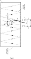
Figure 3 Top view ofFigure 1 ; -
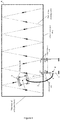
Figure 4 Top view showing the second example of the working device for the inclined surface; -
Figure 5 Enlarged side view of local parts ofFigure 4 ; -
Figure 6 Side view showing the third example of the working device for the inclined surface; - The invention mentioned herein will be further described in detail below with reference to the attached drawings and examples. It is understood that the specific examples described herein are merely illustrative of the invention and are not limited to the invention.
- The invention mentioned herein refers to a working device for working on the inclined surface, consisting of a working robot and a trailer that runs on an inclined surface, and a cable connecting the working robot and the trailer. The working robot and the trailer detect the relative positions via the positioning system, so the trailer can recognize the position of the working robot and follow the working robot autonomously. The trailer is equipped with a power supply to supply continuous power to the working robot via the cable. The working device mentioned herein and its application method will be specifically described below as an example.
- The example of the invention for cleaning solar power stations is shown in
Figure 1 . The solar power station consists of one or more solar panel arrays A, which are composed of one or more solar panels. The surface of the solar panel array A is inclined toward the direction of the sun. The cleaning device of the solar power station consists of acleaning robot 1 and atrailer 2 that are cleaning each solar panel array, as well as acable 3 connecting thecleaning robot 1 and thetrailer 2. - There is a positioning system detecting mutual position between the cleaning
robot 1 and thetrailer 2. As shown inFigure 3 , the positioning system is composed of a wireless distance-measuringunit 4. Two wireless distance-measuringunits 4 are provided on thetrailer 2. A wireless distance-measuring unit 5 is provided on thecleaning robot 1. The wireless distance-measuring units can communicate with each other and detect the distance between each other. Thus, thetrailer 2 can recognize the position of the cleaningrobot 1 and follow thecleaning robot 1 for autonomous movement. An orientation sensor is mounted on thetrailer 2, of which the signal is used to maintain its linear motion. The cleaning tools, such as rotating brushes, are provided on the front and rear sides of the cleaningrobot 1 respectively. - The power supply is equipped on the
trailer 2, which supplies the continuous power for the cleaning work of the cleaningrobot 1 via thecable 3. For example, thetrailer 2 is loaded with a large-capacity battery, and thecleaning robot 1 is continuously powered via thecable 3. - An orientation senor and an edge detecting sensor are provided on the
cleaning robot 1. With the signal from the orientation senor, the cleaningrobot 1 can maintain its direction of motion; with the signal from the edge detecting sensor, the cleaningrobot 1 can judge the edge of the solar panel array A. - Therefore, the cleaning
robot 1 can autonomously move on the solar panel array A according to a predetermined cleaning path (dashed line inFigure 3 ) and ensure that it does not fall off the solar panel array. When the cleaningrobot 1 moves to the end of the solar panel array A, the edge detecting sensor of the cleaningrobot 1 is triggered by the edge of the solar panel array A multiple times in a short time, and the cleaning is thought to have completed. A signal indicator is provided on thecleaning robot 1 to issue a prompt signal. - As shown in
Figure 3 , since two wireless distance-measuringunits 4 are mounted on thetrailer 2, there is a certain distance between the two wireless distance-measuringunits 4, which is indicated as L1. Moreover, one distance-measuring unit 5 is mounted on thecleaning robot 1. The three distance-measuring units can communicate with each other and measure the distance between each other. Then, the two distances measured by the distance-measuring unit of the cleaningrobot 1 and the two distance-measuring units of thetrailer 2 are denoted as L2 and L3 respectively. A triangle of a known side lengths can be formed between the cleaningrobot 1 and thetrailer 2. Based on the triangle, the cleaningrobot 1 and thetrailer 2 can determine their relative position, so that thetrailer 2 can follow thecleaning robot 1 autonomously. - A conduit is included in the
cable 3 connecting thecleaning robot 1 and thetrailer 2. A raw material box is provided on the trailer, and the cleaning materials, such as water are cleaning agent, are supplied to the cleaning robot. - To facilitate handling, the volume and weight of the
trailer 2 are designed as small as possible. If thetrailer 2 is designed to be small (For example, it is assembled with small wheels, compact body and small power motor), thetrailer 2's traveling ability, obstacle performance and driving performance will be affected. Solar power stations are usually built in deserts and farmland, where the ground is uneven and there will be a large number of pits and bulges. Moving on such a ground puts high requirements for thetrailer 2 on overcoming obstacles and driving performance. Obviously, the higher the frame of thetrailer 2, the larger the wheel, the greater the driving power and the better the traveling ability on the complex ground surface, but the weight and volume of the frame will also become larger, which is not conducive to daily maintenance. For example, a worker needs to recover thetrailer 2 and charge it every day. If thetrailer 2 becomes bigger and heavier, it will be very difficult for the workers. - To solve the above problem, the
trailer 2 is designed in a split manner as shown inFigure 2 . As another example of the invention, thetrailer 2 is composed of aframe 6 and adetachable part 7. Thedetachable part 7 consists of a battery, and/or a controller, and/or a raw material box. Theframe 6 can be designed to be tall, large and heavy according to the road conditions, which is placed in the solar power station for a long time. Thedetachable part 7 requires scheduled maintenance, special maintenance and protection (For example, the battery pack, the control circuit board and the raw material box). Taking daily battery charging as an example, the worker only needs to take off the detachable part of the battery pack and take it back to the charging center, which greatly reduces the labor intensity of the worker. - In the above example, with the signal of the orientation sensor, the trailer can maintain the direction of linear motion along the solar panel arrays. This method has the following problems, which may cause the trailer to collide with the solar panel arrays.
- (1) The orientaion sensor is unstable and is prone to generating severe errors. For example, the compass sensor based on the magnetic field is highly susceptible to interference from a peripheral magnetic field; the orientaion sensor based on acceleration variation is highly prone to cumulative errors.
- (2) The orientaion sensor can ensure that the trailer moves linearly, but it is not suitable for the case where the solar panel arrays are not linearly arranged, for example, a solar panel array arranged in a curved shape.
- Therefore, a better solution is proposed in this invention. An edge detection device is mounted on the
trailer 2, which can detect the edge of the solar panel array A. It is fixed to thetrailer 2 via asensor holder 8. With the help of the edge detection device, the trailer knows its relative position to the solar panel arrays so that it can move smoothly along the solar panel arrays. - To better understand it working principle, a scheme of an edge detection device will be described in detail herein. The edge detection device consists of two object sensing sets, and each object sensing set are composed of two object sensing cells installed at high and low positions.
- As shown in
Figure 4 , the edge detection device consists of four object sensing cells, which are divided into two sets, two in each set, respectively mounted on thesensor holders 8 on both sides of thetrailer 2, labeled G1, G2, G3 and G4. The partially enlarged schematic view showing the relative position between the object sensing cells and the edge of the solar panel array A is shown inFigure 5 . When the edge detection device is in operation, the object sensing cell at the higher position is located directly above the inclined surface, which can detect the inclined surface, and the object sensing cell at the lower position is located beyond the inclined surface, which cannot detect the inclined surface. The object sensing cells are respectively located on the upper and lower sides of the edge of the solar panel array A. One object sensing cell can detect the solar panel, and the other object sensing cell cannot detect the solar panel. The relative position between thetrailer 2 and the solar panel array A can be known by checking the status of the four object sensing cells. The direction and moving path of thetrailer 2 can be adjusted such that it can always move along the solar panel array A, of which edge serves as the reference. For example, when G1 and G3 sense the solar panel, but G2 and G4 do not detect the solar panel, then thetrailer 2 maintains a desirable position from the edge of the solar panel array A; when only G1 senses the solar panel, but G3, G2 and G4 do not perceive the solar panel, it indicates that thetrailer 2 has been seriously skewed relative to the edge of the solar panel array A. Then, the direction of thetrailer 2 shall be adjusted in time to help thetrailer 2 to resume the desirable relative position with the edge of the solar panel array A. After the edge detection device is installed on thetrailer 2, a closed loop control system is formed; even if there are some external disturbances (For example, the road surface is not flat, the solar panel array is not strictly aligned and the wheels of the trailer have a speed difference in rotation), thetrailer 2 can move smoothly along the edge of the solar panel array A. At the same time, the wireless distance-measuringunits 4 and 5 are respectively installed on thetrailer 2 and thecleaning robot 1, so that the distance L between the two units is measured. Thetrailer 2 moves accordingly to maintain the distance L, keeping both units at an appropriate distance and ensuring that thecable 3 is not over tensioned. The cleaning tools, such as rotating brushes, are provided on the front and rear sides of the cleaningrobot 1 respectively. - Referring to the third example, the edge detection device can also be equipped with the image processing technology. As shown in
Figure 6 , thecamera 9 is mounted on thetrailer 2, which can capture an image of the solar panel array A and its edges. The captured image is analyzed by an appropriate image processing system (For example, analyzed against the color of the solar panel array frame or the color change between the solar panel array and the ground) to obtain the pixel coordinates of the lower edge of the solar panel array A. In this way, the position and position of thetrailer 2 relative to the lower edge can be adjusted accordingly, to ensure that thetrailer 2 moves generally along the edge of the solar panel array A. - The cleaning method of the Solar power station with the cleaning device can be carried out by taking the following steps:
- Step 1: Carry the
cleaning robot 1, thetrailer 2 or the detachable parts of the trailer to the site of the solar power station; - Step 2: Manually place the cleaning
robot 1 on a solar panel array A to be cleaned, and connect thecleaning robot 1 to thetrailer 2 with thecable 3. Turn on thecleaning robot 1 to automatically clean the solar panel array A. During the cleaning work, thetrailer 2 automatically follows the cleaningrobot 1 to move; - Step 3: The cleaning
robot 1 performs automatic cleaning on the solar panel array A along the predetermined cleaning path, and the signal indicator issues the prompt signal after the cleaning is completed; - Step 4: Manually move the
cleaning robot 1 to another solar panel array A to be cleaned, and repeatsteps - With the method mentioned above, one worker can simultaneously manage and operate multiple sets of such cleaning devices. Based on the actual trial operation, one worker can operate and manage 30 to 50 cleaning devices at the same time, who is responsible for placing the
cleaning robot 1 and moving the cleaning robot between the solar panel arrays A. Once the cleaningrobot 1 is placed, the cleaningrobot 1 and thetrailer 2 can start cleaning automatically. After cleaning one solar panel array A, the cleaningrobot 1 issues a prompt signal to the worker, who can come over to move thecleaning robot 1 to the next solar panel array A, and then continues to clean. - The cleaning method of the solar power station with the cleaning device can be carried out in the following steps:
- Step 1: Carry the
cleaning robot 1, thetrailer 2 or the detachable parts of the trailer to the site of the solar power station; - Step 2: Manually place the cleaning
robot 1 on a solar panel array A to be cleaned, and connect thecleaning robot 1 to thetrailer 2 with thecable 3. Turn on the cleaning robot to automatically clean the solar panel arrays, which is followed by thetrailer 2 directed by the edge detection device thereon constantly, so it can adjust the position and direction automatically along the edge of the solar panel arrays and follow the movement of the cleaningrobot 1; - Step 3: The cleaning
robot 1 performs automatic cleaning on the solar panel array A along the predetermined cleaning path, and the signal indicator issues the prompt signal after the cleaning is completed; - Step 4: Manually move the
cleaning robot 1 to another solar panel array A to be cleaned, and repeatsteps - The examples mentioned above are only the reference for the operation of the invention herein, which are not limited to the invention herein. Any modifications, equivalent substitutions and improvements made within the spirit and principles of the invention shall be covered in the invention patent.
Claims (11)
- The working device is designed for working on an inclined surface, consisting of the working robot working on an inclined surface and the trailer, as well as the cable connecting the working robot and the trailer. The working robot and the trailer are equipped with the positioning system detecting their relative positions, so the trailer can recognize the position of the working robot and follow the working robot to move autonomously. The trailer is equipped with a power supply to provide continuous power to the working robot via the cable.
- The working device for the inclined surface mentioned in 1 herein features an orientation sensor and edge detection sensor, so that it can move autonomously on the inclined surface according to a predetermined working path. A signal indicator is provided on the working robot, which issues a prompt signal after the operation is completed.
- The working device for the inclined surface mentioned in 1 herein has a conduit in the cable between the working robot and the trailer. The raw material box is equipped on the trailer, which provides the raw materials required for the operation of the working robot.
- The working device for the inclined surface mentioned in 1 or 3 herein features the trailer composed of a frame and a detachable part.
- The working device for the inclined surface mentioned in 1 herein is designed with an edge detection device on the trailer capable of detecting an edge of the inclined surface.
- The working device for the inclined surface mentioned in 5 herein features the inclined surface made of an solar panel arrays and the edge detection device on the trailer capable of detecting an edge of the solar panel array.
- The working device for the inclined surface mentioned in 5 or 6 herein features the edge detection device with two object sensing sets.
- The working device for the inclined surface mentioned in 7 herein features two object sensing cells in each object sensing set.
- The working device for the inclined surface mentioned in 5 or 6 herein is characterized with a camera and an image processing system mounted on the trailer. The camera can capture an image of the inclined surface and the edge thereof, and the captured image is transmitted to the image processing system for analysis and processing in real time. The pixel coordinates of the lower edge of the inclined surface in the image are obtained, by which the position and direction of the trailer relative to the lower edge of the inclined surface can be identified. The position and direction of the trailer can be adjusted accordingly to ensure that the trailer moves roughly along the edge of the inclined surface.
- The cleaning method is for cleaning the solar power station comprising one or more solar panel arrays. solar panel array is composed of one or more solar panel. The inclined surface can be cleaned with the working device mentioned from 1 to 9 herein. The inclined surface refers to the surface of the solar panel arrays. The operation mentioned herein refers to the cleaning work, and the working robot refers to the cleaning robot. The cleaning work can be performed in the following steps:Step 1. Transport the cleaning robot and the trailer to the site of the solar power station;Step 2: Manually place the cleaning robot on the solar panel array to be cleaned, and connect the cleaning robot to the trailer with a cable; turn on the cleaning robot to automatically clean the solar panel arrays, which is followed by the trailer automatically;Step 3: The cleaning robot performs automatic cleaning on the surface of the solar panel array along the predetermined cleaning path, and sends the prompt signal after the cleaning is completed;Step 4: Manually move the cleaning robot to another solar panel array to be cleaned, and repeat steps 2 and 3.
- The cleaning method is for the solar power station comprising one or more solar panel arrays. The solar panel array composed of one or more solar panel modules. The inclined surface can be cleaned with the working device mentioned in 7 herein. The inclined surface refers to the surface of the solar panel array. The operation mentioned herein refers to the cleaning work, and the working robot refers to the cleaning robot. The cleaning work involves the following steps:Step 1: Carry the cleaning robot and the trailer to the site of the solar power station;Step 2: Manually place the cleaning robot on the solar panel array to be cleaned, and connect the cleaning robot to the trailer with a cable. Turn on the cleaning robot to automatically clean the solar panel arrays, which is followed by the trailer directed by the edge detection device thereon constantly, so it can adjust the position and direction automatically along the edge of the solar panel arrays and follow the movement of the cleaning robot;Step 3: The cleaning robot performs automatic cleaning on the surface of the solar panel array along the predetermined cleaning track, and issues the prompt signal after the cleaning is completed;Step 4: Manually move the cleaning robot to another solar panel array to be cleaned, and repeat steps 2 and 3.
Applications Claiming Priority (1)
| Application Number | Priority Date | Filing Date | Title |
|---|---|---|---|
| CN201710720195.0A CN107362994A (en) | 2017-08-21 | 2017-08-21 | Apparatus for work in inclined plane and its apply cleaning method in photovoltaic plant |
Publications (2)
| Publication Number | Publication Date |
|---|---|
| EP3446951A1 true EP3446951A1 (en) | 2019-02-27 |
| EP3446951B1 EP3446951B1 (en) | 2022-01-05 |
Family
ID=60310359
Family Applications (1)
| Application Number | Title | Priority Date | Filing Date |
|---|---|---|---|
| EP18189863.6A Not-in-force EP3446951B1 (en) | 2017-08-21 | 2018-08-21 | Working device on inclined surface and cleaning method applied in solar power station |
Country Status (4)
| Country | Link |
|---|---|
| US (1) | US10955850B2 (en) |
| EP (1) | EP3446951B1 (en) |
| JP (1) | JP6948296B2 (en) |
| CN (2) | CN107362994A (en) |
Families Citing this family (19)
| Publication number | Priority date | Publication date | Assignee | Title |
|---|---|---|---|---|
| CN107947723B (en) * | 2017-11-23 | 2020-11-03 | 浙江国自机器人技术有限公司 | Cleaning method of photovoltaic cleaning robot |
| CN107966986A (en) * | 2017-11-23 | 2018-04-27 | 浙江国自机器人技术有限公司 | A kind of robot and its air navigation aid, system, equipment |
| KR102063561B1 (en) * | 2017-12-21 | 2020-02-11 | (주)디엠비에이치 | Dust Cleaning Robot |
| US10575699B2 (en) * | 2018-01-05 | 2020-03-03 | Irobot Corporation | System for spot cleaning by a mobile robot |
| US11638939B2 (en) * | 2018-11-27 | 2023-05-02 | Steam Tech, Llc | Mobile panel cleaner |
| USD938114S1 (en) * | 2019-03-22 | 2021-12-07 | Sungrow Power Supply Co., Ltd. | Intelligent cleaning robot |
| CN110125124B (en) * | 2019-05-14 | 2021-07-20 | 合肥仁洁智能科技有限公司 | Photovoltaic cleaning machine tilt attitude detection method, controller and photovoltaic cleaning machine |
| KR102334755B1 (en) * | 2019-08-28 | 2021-12-06 | 한국기계연구원 | Solar panel cleaning device having cleaning module |
| CN111332977A (en) * | 2020-03-06 | 2020-06-26 | 北京中电博顺智能设备技术有限公司 | A transition device and its control method |
| CN112093741B (en) * | 2020-09-23 | 2025-09-16 | 浙江大学 | Inclined plane mobile machine and multi-robot system and method of use thereof |
| JP2022175834A (en) * | 2021-05-14 | 2022-11-25 | 株式会社Ihi | Solar panel cleaning system, and cleaning path generation device |
| CN113477592A (en) * | 2021-07-13 | 2021-10-08 | 苏州热工研究院有限公司 | Cleaning device and method for secondary side hard sludge of steam generator |
| CN114942635B (en) | 2022-04-30 | 2024-12-24 | 苏州瑞得恩光能科技有限公司 | A robot and a linear motion control method and data processing device thereof |
| CN114737801A (en) * | 2022-05-23 | 2022-07-12 | 金螳螂精装科技(苏州)有限公司 | A sun room designed to automatically clean the top surface to prevent dust accumulation |
| CN115121528A (en) * | 2022-07-27 | 2022-09-30 | 湖州丽天智能科技有限公司 | Photovoltaic cleaning system and cleaning method |
| CN116360467B (en) * | 2023-06-01 | 2023-08-15 | 中国科学院自动化研究所 | Autonomous cruising system and autonomous cruising method for unmanned cleaning device of photovoltaic panel column |
| CN117021105B (en) * | 2023-08-30 | 2024-10-22 | 北京瑞科同创科技股份有限公司 | Control method, device and equipment of photovoltaic cleaning robot |
| CN118270193B (en) * | 2024-03-25 | 2026-08-11 | 南通理工学院 | A recyclable wall-climbing vehicle device and a method for adjusting the attitude of the wall-climbing vehicle. |
| CN120395843A (en) * | 2025-05-13 | 2025-08-01 | 绍兴实界智能科技有限公司 | A multifunctional photovoltaic maintenance intelligent robot system compatible with complex terrain |
Citations (3)
| Publication number | Priority date | Publication date | Assignee | Title |
|---|---|---|---|---|
| JPS60259388A (en) * | 1984-06-01 | 1985-12-21 | バブコツク日立株式会社 | Wall-surface travelling robot device |
| CN105149253B (en) * | 2015-06-24 | 2017-06-13 | 中国科学院合肥物质科学研究院 | Solar panel clearing apparatus and system |
| EP3392124A1 (en) * | 2017-04-19 | 2018-10-24 | Zhejiang University | Multifunctional robot system and method |
Family Cites Families (24)
| Publication number | Priority date | Publication date | Assignee | Title |
|---|---|---|---|---|
| JPH0789295B2 (en) * | 1986-06-09 | 1995-09-27 | 株式会社ダイフク | Travel control equipment for mobile vehicles |
| JPS6421511A (en) * | 1987-07-16 | 1989-01-24 | Kubota Ltd | Working car with steering control device |
| JPH07265827A (en) * | 1994-03-29 | 1995-10-17 | Sumitomo Constr Mach Co Ltd | Powder deposit remover |
| JP2970990B2 (en) * | 1994-04-14 | 1999-11-02 | 新キャタピラー三菱株式会社 | Wall treatment machine |
| JPH11220003A (en) * | 1998-02-03 | 1999-08-10 | Shin Meiwa Ind Co Ltd | Wafer holding device |
| JP2002029671A (en) * | 2000-07-13 | 2002-01-29 | Nihon Bisoh Co Ltd | Arrangement structure of optical information transmission / reception equipment |
| CN101010151B (en) * | 2004-09-03 | 2012-01-11 | 松下电器产业株式会社 | Substrate edge part cleaning apparatus and substrate edge part cleaning method |
| US20060048800A1 (en) * | 2004-09-09 | 2006-03-09 | Rast Rodger H | Automated building exterior cleaning apparatus |
| JP4477685B1 (en) * | 2008-12-26 | 2010-06-09 | 三井造船株式会社 | Cleaning robot system and control method thereof |
| JP2012139792A (en) * | 2011-01-05 | 2012-07-26 | Mitsui Eng & Shipbuild Co Ltd | Cleaning robot system, and method for controlling the same |
| DE102012103574B4 (en) * | 2012-04-24 | 2018-03-29 | MULAG FAHRZEUGWERK Heinz Wössner GmbH & Co. KG | Cleaning device and cleaning method for even cleaning surfaces |
| US8948995B2 (en) * | 2012-06-28 | 2015-02-03 | Toyota Motor Engineering & Manufacturing North America, Inc. | Preceding vehicle state prediction |
| US20140062061A1 (en) * | 2012-08-31 | 2014-03-06 | Robotex Inc. | Trailer and hitch system and method |
| JP2014232795A (en) * | 2013-05-29 | 2014-12-11 | 東レエンジニアリング株式会社 | Solar battery panel washing system |
| JP6376732B2 (en) * | 2013-07-18 | 2018-08-22 | Ihi運搬機械株式会社 | Contactless power supply system |
| CN103926253B (en) * | 2014-04-22 | 2017-04-12 | 哈尔滨工业大学 | Infrared Thermal Wave Nondestructive Testing Method and System Excited by Linear Frequency Modulation Ultrasonic |
| JP6404348B2 (en) * | 2014-06-25 | 2018-10-17 | 株式会社未来機械 | Self-propelled robot |
| CN204107929U (en) * | 2014-08-28 | 2015-01-21 | 金丹 | The comprehensive cleaning device of solar power station |
| CN205945631U (en) * | 2016-06-23 | 2017-02-08 | 汉能联创移动能源投资有限公司 | Photovoltaic power plant's self - cleaning device |
| CN106160649A (en) * | 2016-07-29 | 2016-11-23 | 无锡信大气象传感网科技有限公司 | Self-cleaning type solar energy photovoltaic panel |
| CN106269624B (en) * | 2016-09-21 | 2019-03-08 | 苏州瑞得恩光能科技有限公司 | Solar panel cleaning robot |
| CN206211936U (en) * | 2016-11-17 | 2017-05-31 | 浙江国自机器人技术有限公司 | A kind of photovoltaic array straddle cleaning device |
| CN106926253A (en) * | 2017-04-19 | 2017-07-07 | 浙江大学 | Multifunctional robot system and its application |
| CN106903101B (en) * | 2017-04-28 | 2019-04-12 | 浙江海鸿工业产品设计有限公司 | A kind of intelligent photovoltaic component cleaning device |
-
2017
- 2017-08-21 CN CN201710720195.0A patent/CN107362994A/en active Pending
-
2018
- 2018-08-09 CN CN201810900530.XA patent/CN109420629B/en active Active
- 2018-08-20 JP JP2018154133A patent/JP6948296B2/en not_active Expired - Fee Related
- 2018-08-21 US US16/107,690 patent/US10955850B2/en not_active Expired - Fee Related
- 2018-08-21 EP EP18189863.6A patent/EP3446951B1/en not_active Not-in-force
Patent Citations (3)
| Publication number | Priority date | Publication date | Assignee | Title |
|---|---|---|---|---|
| JPS60259388A (en) * | 1984-06-01 | 1985-12-21 | バブコツク日立株式会社 | Wall-surface travelling robot device |
| CN105149253B (en) * | 2015-06-24 | 2017-06-13 | 中国科学院合肥物质科学研究院 | Solar panel clearing apparatus and system |
| EP3392124A1 (en) * | 2017-04-19 | 2018-10-24 | Zhejiang University | Multifunctional robot system and method |
Also Published As
| Publication number | Publication date |
|---|---|
| CN107362994A (en) | 2017-11-21 |
| EP3446951B1 (en) | 2022-01-05 |
| US10955850B2 (en) | 2021-03-23 |
| JP6948296B2 (en) | 2021-10-13 |
| JP2019034306A (en) | 2019-03-07 |
| CN109420629B (en) | 2020-05-22 |
| CN109420629A (en) | 2019-03-05 |
| US20190056744A1 (en) | 2019-02-21 |
Similar Documents
| Publication | Publication Date | Title |
|---|---|---|
| US10955850B2 (en) | Working device on inclined surface and cleaning method applied in solar power station | |
| US20240190009A1 (en) | Automated solar robot system and method | |
| US12158759B2 (en) | Docking method | |
| JP6404348B2 (en) | Self-propelled robot | |
| US8046101B2 (en) | Cleaning robot system and method of controlling same | |
| CN106272331B (en) | The method for path navigation that robot travels in rectangular slope | |
| CN115889271B (en) | A photovoltaic cleaning method combined with drones | |
| US20130133172A1 (en) | Method for the automated mounting of modules on receiving devices, in particular solar modules on stands and mobile mounting device for such modules | |
| CN107544519A (en) | Solar panel sweeping robot docking system and its method of plugging into | |
| CN209460646U (en) | A kind of robot cleaner for photovoltaic module hardware system | |
| CN105149253A (en) | Solar cell panel cleaning device and system | |
| CN106325267A (en) | Omnidirectional mobile platform vehicle with automatic line patrolling and obstacle avoiding functions | |
| CN109039264B (en) | Automatic cross-row photovoltaic panel cleaning and defect detection system device | |
| CN206854321U (en) | A kind of AGV dollies for transporting solar power station photovoltaic board cleaning device | |
| CN114754822B (en) | Multiple information intelligent fusion acquisition, study and judgment decision robot based on intelligent agriculture and use method thereof | |
| CN110640759B (en) | Full-automatic road garbage picking robot and using method thereof | |
| CN217657441U (en) | Automatic robot system that gathers of domestic fungus | |
| CN114946540A (en) | Automatic robot system that gathers of domestic fungus | |
| CN103955150A (en) | Semi-automatic intelligent tennis pick-up robot and control method thereof | |
| CN115351797A (en) | Photovoltaic panel cleaning equipment | |
| CN106248083B (en) | A kind of method for path navigation that robot travels in rectangular slope | |
| CN106584454B (en) | A kind of path navigation control method that robot travels in rectangular slope | |
| CN212256105U (en) | An intelligent trolley for line inspection in substations | |
| CN114161386A (en) | Photovoltaic module cleaning device intelligent movement robot | |
| CN111352412B (en) | Intelligent track inspection robot |
Legal Events
| Date | Code | Title | Description |
|---|---|---|---|
| PUAI | Public reference made under article 153(3) epc to a published international application that has entered the european phase |
Free format text: ORIGINAL CODE: 0009012 |
|
| STAA | Information on the status of an ep patent application or granted ep patent |
Free format text: STATUS: THE APPLICATION HAS BEEN PUBLISHED |
|
| AK | Designated contracting states |
Kind code of ref document: A1 Designated state(s): AL AT BE BG CH CY CZ DE DK EE ES FI FR GB GR HR HU IE IS IT LI LT LU LV MC MK MT NL NO PL PT RO RS SE SI SK SM TR |
|
| AX | Request for extension of the european patent |
Extension state: BA ME |
|
| RIN1 | Information on inventor provided before grant (corrected) |
Inventor name: LI, XIN |
|
| STAA | Information on the status of an ep patent application or granted ep patent |
Free format text: STATUS: REQUEST FOR EXAMINATION WAS MADE |
|
| 17P | Request for examination filed |
Effective date: 20190813 |
|
| RBV | Designated contracting states (corrected) |
Designated state(s): AL AT BE BG CH CY CZ DE DK EE ES FI FR GB GR HR HU IE IS IT LI LT LU LV MC MK MT NL NO PL PT RO RS SE SI SK SM TR |
|
| STAA | Information on the status of an ep patent application or granted ep patent |
Free format text: STATUS: EXAMINATION IS IN PROGRESS |
|
| 17Q | First examination report despatched |
Effective date: 20200121 |
|
| GRAP | Despatch of communication of intention to grant a patent |
Free format text: ORIGINAL CODE: EPIDOSNIGR1 |
|
| STAA | Information on the status of an ep patent application or granted ep patent |
Free format text: STATUS: GRANT OF PATENT IS INTENDED |
|
| RIC1 | Information provided on ipc code assigned before grant |
Ipc: F24S 40/20 20180101ALI20210917BHEP Ipc: E04G 23/00 20060101ALI20210917BHEP Ipc: H02S 40/10 20140101ALI20210917BHEP Ipc: B08B 1/00 20060101ALI20210917BHEP Ipc: B08B 13/00 20060101ALI20210917BHEP Ipc: B62D 57/024 20060101AFI20210917BHEP |
|
| INTG | Intention to grant announced |
Effective date: 20211027 |
|
| GRAS | Grant fee paid |
Free format text: ORIGINAL CODE: EPIDOSNIGR3 |
|
| GRAA | (expected) grant |
Free format text: ORIGINAL CODE: 0009210 |
|
| STAA | Information on the status of an ep patent application or granted ep patent |
Free format text: STATUS: THE PATENT HAS BEEN GRANTED |
|
| AK | Designated contracting states |
Kind code of ref document: B1 Designated state(s): AL AT BE BG CH CY CZ DE DK EE ES FI FR GB GR HR HU IE IS IT LI LT LU LV MC MK MT NL NO PL PT RO RS SE SI SK SM TR |
|
| REG | Reference to a national code |
Ref country code: GB Ref legal event code: FG4D |
|
| REG | Reference to a national code |
Ref country code: CH Ref legal event code: EP |
|
| REG | Reference to a national code |
Ref country code: AT Ref legal event code: REF Ref document number: 1460300 Country of ref document: AT Kind code of ref document: T Effective date: 20220115 |
|
| REG | Reference to a national code |
Ref country code: DE Ref legal event code: R096 Ref document number: 602018029014 Country of ref document: DE |
|
| REG | Reference to a national code |
Ref country code: IE Ref legal event code: FG4D |
|
| REG | Reference to a national code |
Ref country code: LT Ref legal event code: MG9D |
|
| REG | Reference to a national code |
Ref country code: NL Ref legal event code: MP Effective date: 20220105 |
|
| REG | Reference to a national code |
Ref country code: AT Ref legal event code: MK05 Ref document number: 1460300 Country of ref document: AT Kind code of ref document: T Effective date: 20220105 |
|
| PG25 | Lapsed in a contracting state [announced via postgrant information from national office to epo] |
Ref country code: NL Free format text: LAPSE BECAUSE OF FAILURE TO SUBMIT A TRANSLATION OF THE DESCRIPTION OR TO PAY THE FEE WITHIN THE PRESCRIBED TIME-LIMIT Effective date: 20220105 |
|
| PG25 | Lapsed in a contracting state [announced via postgrant information from national office to epo] |
Ref country code: SE Free format text: LAPSE BECAUSE OF FAILURE TO SUBMIT A TRANSLATION OF THE DESCRIPTION OR TO PAY THE FEE WITHIN THE PRESCRIBED TIME-LIMIT Effective date: 20220105 Ref country code: RS Free format text: LAPSE BECAUSE OF FAILURE TO SUBMIT A TRANSLATION OF THE DESCRIPTION OR TO PAY THE FEE WITHIN THE PRESCRIBED TIME-LIMIT Effective date: 20220105 Ref country code: PT Free format text: LAPSE BECAUSE OF FAILURE TO SUBMIT A TRANSLATION OF THE DESCRIPTION OR TO PAY THE FEE WITHIN THE PRESCRIBED TIME-LIMIT Effective date: 20220505 Ref country code: NO Free format text: LAPSE BECAUSE OF FAILURE TO SUBMIT A TRANSLATION OF THE DESCRIPTION OR TO PAY THE FEE WITHIN THE PRESCRIBED TIME-LIMIT Effective date: 20220405 Ref country code: LT Free format text: LAPSE BECAUSE OF FAILURE TO SUBMIT A TRANSLATION OF THE DESCRIPTION OR TO PAY THE FEE WITHIN THE PRESCRIBED TIME-LIMIT Effective date: 20220105 Ref country code: HR Free format text: LAPSE BECAUSE OF FAILURE TO SUBMIT A TRANSLATION OF THE DESCRIPTION OR TO PAY THE FEE WITHIN THE PRESCRIBED TIME-LIMIT Effective date: 20220105 Ref country code: ES Free format text: LAPSE BECAUSE OF FAILURE TO SUBMIT A TRANSLATION OF THE DESCRIPTION OR TO PAY THE FEE WITHIN THE PRESCRIBED TIME-LIMIT Effective date: 20220105 Ref country code: BG Free format text: LAPSE BECAUSE OF FAILURE TO SUBMIT A TRANSLATION OF THE DESCRIPTION OR TO PAY THE FEE WITHIN THE PRESCRIBED TIME-LIMIT Effective date: 20220405 |
|
| PG25 | Lapsed in a contracting state [announced via postgrant information from national office to epo] |
Ref country code: PL Free format text: LAPSE BECAUSE OF FAILURE TO SUBMIT A TRANSLATION OF THE DESCRIPTION OR TO PAY THE FEE WITHIN THE PRESCRIBED TIME-LIMIT Effective date: 20220105 Ref country code: LV Free format text: LAPSE BECAUSE OF FAILURE TO SUBMIT A TRANSLATION OF THE DESCRIPTION OR TO PAY THE FEE WITHIN THE PRESCRIBED TIME-LIMIT Effective date: 20220105 Ref country code: GR Free format text: LAPSE BECAUSE OF FAILURE TO SUBMIT A TRANSLATION OF THE DESCRIPTION OR TO PAY THE FEE WITHIN THE PRESCRIBED TIME-LIMIT Effective date: 20220406 Ref country code: FI Free format text: LAPSE BECAUSE OF FAILURE TO SUBMIT A TRANSLATION OF THE DESCRIPTION OR TO PAY THE FEE WITHIN THE PRESCRIBED TIME-LIMIT Effective date: 20220105 Ref country code: AT Free format text: LAPSE BECAUSE OF FAILURE TO SUBMIT A TRANSLATION OF THE DESCRIPTION OR TO PAY THE FEE WITHIN THE PRESCRIBED TIME-LIMIT Effective date: 20220105 |
|
| PG25 | Lapsed in a contracting state [announced via postgrant information from national office to epo] |
Ref country code: IS Free format text: LAPSE BECAUSE OF FAILURE TO SUBMIT A TRANSLATION OF THE DESCRIPTION OR TO PAY THE FEE WITHIN THE PRESCRIBED TIME-LIMIT Effective date: 20220505 |
|
| REG | Reference to a national code |
Ref country code: DE Ref legal event code: R097 Ref document number: 602018029014 Country of ref document: DE |
|
| PG25 | Lapsed in a contracting state [announced via postgrant information from national office to epo] |
Ref country code: SM Free format text: LAPSE BECAUSE OF FAILURE TO SUBMIT A TRANSLATION OF THE DESCRIPTION OR TO PAY THE FEE WITHIN THE PRESCRIBED TIME-LIMIT Effective date: 20220105 Ref country code: SK Free format text: LAPSE BECAUSE OF FAILURE TO SUBMIT A TRANSLATION OF THE DESCRIPTION OR TO PAY THE FEE WITHIN THE PRESCRIBED TIME-LIMIT Effective date: 20220105 Ref country code: RO Free format text: LAPSE BECAUSE OF FAILURE TO SUBMIT A TRANSLATION OF THE DESCRIPTION OR TO PAY THE FEE WITHIN THE PRESCRIBED TIME-LIMIT Effective date: 20220105 Ref country code: EE Free format text: LAPSE BECAUSE OF FAILURE TO SUBMIT A TRANSLATION OF THE DESCRIPTION OR TO PAY THE FEE WITHIN THE PRESCRIBED TIME-LIMIT Effective date: 20220105 Ref country code: DK Free format text: LAPSE BECAUSE OF FAILURE TO SUBMIT A TRANSLATION OF THE DESCRIPTION OR TO PAY THE FEE WITHIN THE PRESCRIBED TIME-LIMIT Effective date: 20220105 Ref country code: CZ Free format text: LAPSE BECAUSE OF FAILURE TO SUBMIT A TRANSLATION OF THE DESCRIPTION OR TO PAY THE FEE WITHIN THE PRESCRIBED TIME-LIMIT Effective date: 20220105 |
|
| PLBE | No opposition filed within time limit |
Free format text: ORIGINAL CODE: 0009261 |
|
| STAA | Information on the status of an ep patent application or granted ep patent |
Free format text: STATUS: NO OPPOSITION FILED WITHIN TIME LIMIT |
|
| PG25 | Lapsed in a contracting state [announced via postgrant information from national office to epo] |
Ref country code: AL Free format text: LAPSE BECAUSE OF FAILURE TO SUBMIT A TRANSLATION OF THE DESCRIPTION OR TO PAY THE FEE WITHIN THE PRESCRIBED TIME-LIMIT Effective date: 20220105 |
|
| 26N | No opposition filed |
Effective date: 20221006 |
|
| PG25 | Lapsed in a contracting state [announced via postgrant information from national office to epo] |
Ref country code: SI Free format text: LAPSE BECAUSE OF FAILURE TO SUBMIT A TRANSLATION OF THE DESCRIPTION OR TO PAY THE FEE WITHIN THE PRESCRIBED TIME-LIMIT Effective date: 20220105 |
|
| REG | Reference to a national code |
Ref country code: DE Ref legal event code: R119 Ref document number: 602018029014 Country of ref document: DE |
|
| PG25 | Lapsed in a contracting state [announced via postgrant information from national office to epo] |
Ref country code: MC Free format text: LAPSE BECAUSE OF FAILURE TO SUBMIT A TRANSLATION OF THE DESCRIPTION OR TO PAY THE FEE WITHIN THE PRESCRIBED TIME-LIMIT Effective date: 20220105 |
|
| REG | Reference to a national code |
Ref country code: CH Ref legal event code: PL |
|
| GBPC | Gb: european patent ceased through non-payment of renewal fee |
Effective date: 20220821 |
|
| PG25 | Lapsed in a contracting state [announced via postgrant information from national office to epo] |
Ref country code: LU Free format text: LAPSE BECAUSE OF NON-PAYMENT OF DUE FEES Effective date: 20220821 Ref country code: LI Free format text: LAPSE BECAUSE OF NON-PAYMENT OF DUE FEES Effective date: 20220831 Ref country code: CH Free format text: LAPSE BECAUSE OF NON-PAYMENT OF DUE FEES Effective date: 20220831 |
|
| REG | Reference to a national code |
Ref country code: BE Ref legal event code: MM Effective date: 20220831 |
|
| PG25 | Lapsed in a contracting state [announced via postgrant information from national office to epo] |
Ref country code: IT Free format text: LAPSE BECAUSE OF FAILURE TO SUBMIT A TRANSLATION OF THE DESCRIPTION OR TO PAY THE FEE WITHIN THE PRESCRIBED TIME-LIMIT Effective date: 20220105 Ref country code: IE Free format text: LAPSE BECAUSE OF NON-PAYMENT OF DUE FEES Effective date: 20220821 Ref country code: FR Free format text: LAPSE BECAUSE OF NON-PAYMENT OF DUE FEES Effective date: 20220831 Ref country code: DE Free format text: LAPSE BECAUSE OF NON-PAYMENT OF DUE FEES Effective date: 20230301 |
|
| PG25 | Lapsed in a contracting state [announced via postgrant information from national office to epo] |
Ref country code: BE Free format text: LAPSE BECAUSE OF NON-PAYMENT OF DUE FEES Effective date: 20220831 |
|
| PG25 | Lapsed in a contracting state [announced via postgrant information from national office to epo] |
Ref country code: GB Free format text: LAPSE BECAUSE OF NON-PAYMENT OF DUE FEES Effective date: 20220821 |
|
| PG25 | Lapsed in a contracting state [announced via postgrant information from national office to epo] |
Ref country code: HU Free format text: LAPSE BECAUSE OF FAILURE TO SUBMIT A TRANSLATION OF THE DESCRIPTION OR TO PAY THE FEE WITHIN THE PRESCRIBED TIME-LIMIT; INVALID AB INITIO Effective date: 20180821 |
|
| PG25 | Lapsed in a contracting state [announced via postgrant information from national office to epo] |
Ref country code: CY Free format text: LAPSE BECAUSE OF FAILURE TO SUBMIT A TRANSLATION OF THE DESCRIPTION OR TO PAY THE FEE WITHIN THE PRESCRIBED TIME-LIMIT Effective date: 20220105 |
|
| PG25 | Lapsed in a contracting state [announced via postgrant information from national office to epo] |
Ref country code: MK Free format text: LAPSE BECAUSE OF FAILURE TO SUBMIT A TRANSLATION OF THE DESCRIPTION OR TO PAY THE FEE WITHIN THE PRESCRIBED TIME-LIMIT Effective date: 20220105 |
|
| PG25 | Lapsed in a contracting state [announced via postgrant information from national office to epo] |
Ref country code: MT Free format text: LAPSE BECAUSE OF FAILURE TO SUBMIT A TRANSLATION OF THE DESCRIPTION OR TO PAY THE FEE WITHIN THE PRESCRIBED TIME-LIMIT Effective date: 20220105 |
|
| PG25 | Lapsed in a contracting state [announced via postgrant information from national office to epo] |
Ref country code: TR Free format text: LAPSE BECAUSE OF FAILURE TO SUBMIT A TRANSLATION OF THE DESCRIPTION OR TO PAY THE FEE WITHIN THE PRESCRIBED TIME-LIMIT Effective date: 20220105 |