EP3446649B1 - Subintimaler wiedereintrittskatheter - Google Patents
Subintimaler wiedereintrittskatheter Download PDFInfo
- Publication number
- EP3446649B1 EP3446649B1 EP18190670.2A EP18190670A EP3446649B1 EP 3446649 B1 EP3446649 B1 EP 3446649B1 EP 18190670 A EP18190670 A EP 18190670A EP 3446649 B1 EP3446649 B1 EP 3446649B1
- Authority
- EP
- European Patent Office
- Prior art keywords
- tubular member
- catheter
- flexible tubular
- distal
- balloon
- Prior art date
- Legal status (The legal status is an assumption and is not a legal conclusion. Google has not performed a legal analysis and makes no representation as to the accuracy of the status listed.)
- Active
Links
Images


Classifications
-
- A—HUMAN NECESSITIES
- A61—MEDICAL OR VETERINARY SCIENCE; HYGIENE
- A61B—DIAGNOSIS; SURGERY; IDENTIFICATION
- A61B17/00—Surgical instruments, devices or methods
- A61B17/22—Implements for squeezing-off ulcers or the like on inner organs of the body; Implements for scraping-out cavities of body organs, e.g. bones; for invasive removal or destruction of calculus using mechanical vibrations; for removing obstructions in blood vessels, not otherwise provided for
-
- A—HUMAN NECESSITIES
- A61—MEDICAL OR VETERINARY SCIENCE; HYGIENE
- A61B—DIAGNOSIS; SURGERY; IDENTIFICATION
- A61B17/00—Surgical instruments, devices or methods
- A61B17/32—Surgical cutting instruments
- A61B17/3205—Excision instruments
- A61B17/3207—Atherectomy devices working by cutting or abrading; Similar devices specially adapted for non-vascular obstructions
- A61B17/320758—Atherectomy devices working by cutting or abrading; Similar devices specially adapted for non-vascular obstructions with a rotating cutting instrument, e.g. motor driven
-
- A—HUMAN NECESSITIES
- A61—MEDICAL OR VETERINARY SCIENCE; HYGIENE
- A61M—DEVICES FOR INTRODUCING MEDIA INTO, OR ONTO, THE BODY; DEVICES FOR TRANSDUCING BODY MEDIA OR FOR TAKING MEDIA FROM THE BODY; DEVICES FOR PRODUCING OR ENDING SLEEP OR STUPOR
- A61M25/00—Catheters; Hollow probes
- A61M25/0067—Catheters; Hollow probes characterised by the distal end, e.g. tips
- A61M25/0082—Catheter tip comprising a tool
-
- A—HUMAN NECESSITIES
- A61—MEDICAL OR VETERINARY SCIENCE; HYGIENE
- A61M—DEVICES FOR INTRODUCING MEDIA INTO, OR ONTO, THE BODY; DEVICES FOR TRANSDUCING BODY MEDIA OR FOR TAKING MEDIA FROM THE BODY; DEVICES FOR PRODUCING OR ENDING SLEEP OR STUPOR
- A61M25/00—Catheters; Hollow probes
- A61M25/01—Introducing, guiding, advancing, emplacing or holding catheters
- A61M25/0194—Tunnelling catheters
-
- A—HUMAN NECESSITIES
- A61—MEDICAL OR VETERINARY SCIENCE; HYGIENE
- A61M—DEVICES FOR INTRODUCING MEDIA INTO, OR ONTO, THE BODY; DEVICES FOR TRANSDUCING BODY MEDIA OR FOR TAKING MEDIA FROM THE BODY; DEVICES FOR PRODUCING OR ENDING SLEEP OR STUPOR
- A61M25/00—Catheters; Hollow probes
- A61M25/10—Balloon catheters
- A61M25/104—Balloon catheters used for angioplasty
-
- A—HUMAN NECESSITIES
- A61—MEDICAL OR VETERINARY SCIENCE; HYGIENE
- A61B—DIAGNOSIS; SURGERY; IDENTIFICATION
- A61B17/00—Surgical instruments, devices or methods
- A61B17/00234—Surgical instruments, devices or methods for minimally invasive surgery
- A61B2017/00292—Surgical instruments, devices or methods for minimally invasive surgery mounted on or guided by flexible, e.g. catheter-like, means
- A61B2017/003—Steerable
- A61B2017/00318—Steering mechanisms
- A61B2017/00331—Steering mechanisms with preformed bends
-
- A—HUMAN NECESSITIES
- A61—MEDICAL OR VETERINARY SCIENCE; HYGIENE
- A61B—DIAGNOSIS; SURGERY; IDENTIFICATION
- A61B17/00—Surgical instruments, devices or methods
- A61B17/22—Implements for squeezing-off ulcers or the like on inner organs of the body; Implements for scraping-out cavities of body organs, e.g. bones; for invasive removal or destruction of calculus using mechanical vibrations; for removing obstructions in blood vessels, not otherwise provided for
- A61B2017/22051—Implements for squeezing-off ulcers or the like on inner organs of the body; Implements for scraping-out cavities of body organs, e.g. bones; for invasive removal or destruction of calculus using mechanical vibrations; for removing obstructions in blood vessels, not otherwise provided for with an inflatable part, e.g. balloon, for positioning, blocking, or immobilisation
- A61B2017/22061—Implements for squeezing-off ulcers or the like on inner organs of the body; Implements for scraping-out cavities of body organs, e.g. bones; for invasive removal or destruction of calculus using mechanical vibrations; for removing obstructions in blood vessels, not otherwise provided for with an inflatable part, e.g. balloon, for positioning, blocking, or immobilisation for spreading elements apart
-
- A—HUMAN NECESSITIES
- A61—MEDICAL OR VETERINARY SCIENCE; HYGIENE
- A61B—DIAGNOSIS; SURGERY; IDENTIFICATION
- A61B17/00—Surgical instruments, devices or methods
- A61B17/22—Implements for squeezing-off ulcers or the like on inner organs of the body; Implements for scraping-out cavities of body organs, e.g. bones; for invasive removal or destruction of calculus using mechanical vibrations; for removing obstructions in blood vessels, not otherwise provided for
- A61B2017/22051—Implements for squeezing-off ulcers or the like on inner organs of the body; Implements for scraping-out cavities of body organs, e.g. bones; for invasive removal or destruction of calculus using mechanical vibrations; for removing obstructions in blood vessels, not otherwise provided for with an inflatable part, e.g. balloon, for positioning, blocking, or immobilisation
- A61B2017/22065—Functions of balloons
- A61B2017/22071—Steering
-
- A—HUMAN NECESSITIES
- A61—MEDICAL OR VETERINARY SCIENCE; HYGIENE
- A61B—DIAGNOSIS; SURGERY; IDENTIFICATION
- A61B17/00—Surgical instruments, devices or methods
- A61B17/22—Implements for squeezing-off ulcers or the like on inner organs of the body; Implements for scraping-out cavities of body organs, e.g. bones; for invasive removal or destruction of calculus using mechanical vibrations; for removing obstructions in blood vessels, not otherwise provided for
- A61B2017/22094—Implements for squeezing-off ulcers or the like on inner organs of the body; Implements for scraping-out cavities of body organs, e.g. bones; for invasive removal or destruction of calculus using mechanical vibrations; for removing obstructions in blood vessels, not otherwise provided for for crossing total occlusions, i.e. piercing
- A61B2017/22095—Implements for squeezing-off ulcers or the like on inner organs of the body; Implements for scraping-out cavities of body organs, e.g. bones; for invasive removal or destruction of calculus using mechanical vibrations; for removing obstructions in blood vessels, not otherwise provided for for crossing total occlusions, i.e. piercing accessing a blood vessel true lumen from the sub-intimal space
-
- A—HUMAN NECESSITIES
- A61—MEDICAL OR VETERINARY SCIENCE; HYGIENE
- A61B—DIAGNOSIS; SURGERY; IDENTIFICATION
- A61B17/00—Surgical instruments, devices or methods
- A61B17/32—Surgical cutting instruments
- A61B17/3205—Excision instruments
- A61B17/3207—Atherectomy devices working by cutting or abrading; Similar devices specially adapted for non-vascular obstructions
- A61B2017/320733—Atherectomy devices working by cutting or abrading; Similar devices specially adapted for non-vascular obstructions with a flexible cutting or scraping element, e.g. with a whip-like distal filament member
-
- A—HUMAN NECESSITIES
- A61—MEDICAL OR VETERINARY SCIENCE; HYGIENE
- A61M—DEVICES FOR INTRODUCING MEDIA INTO, OR ONTO, THE BODY; DEVICES FOR TRANSDUCING BODY MEDIA OR FOR TAKING MEDIA FROM THE BODY; DEVICES FOR PRODUCING OR ENDING SLEEP OR STUPOR
- A61M25/00—Catheters; Hollow probes
- A61M25/0067—Catheters; Hollow probes characterised by the distal end, e.g. tips
- A61M25/0082—Catheter tip comprising a tool
- A61M2025/0096—Catheter tip comprising a tool being laterally outward extensions or tools, e.g. hooks or fibres
-
- A—HUMAN NECESSITIES
- A61—MEDICAL OR VETERINARY SCIENCE; HYGIENE
- A61M—DEVICES FOR INTRODUCING MEDIA INTO, OR ONTO, THE BODY; DEVICES FOR TRANSDUCING BODY MEDIA OR FOR TAKING MEDIA FROM THE BODY; DEVICES FOR PRODUCING OR ENDING SLEEP OR STUPOR
- A61M25/00—Catheters; Hollow probes
- A61M25/01—Introducing, guiding, advancing, emplacing or holding catheters
- A61M2025/018—Catheters having a lateral opening for guiding elongated means lateral to the catheter
-
- A—HUMAN NECESSITIES
- A61—MEDICAL OR VETERINARY SCIENCE; HYGIENE
- A61M—DEVICES FOR INTRODUCING MEDIA INTO, OR ONTO, THE BODY; DEVICES FOR TRANSDUCING BODY MEDIA OR FOR TAKING MEDIA FROM THE BODY; DEVICES FOR PRODUCING OR ENDING SLEEP OR STUPOR
- A61M25/00—Catheters; Hollow probes
- A61M25/01—Introducing, guiding, advancing, emplacing or holding catheters
- A61M25/0194—Tunnelling catheters
- A61M2025/0197—Tunnelling catheters for creating an artificial passage within the body, e.g. in order to go around occlusions
-
- A—HUMAN NECESSITIES
- A61—MEDICAL OR VETERINARY SCIENCE; HYGIENE
- A61M—DEVICES FOR INTRODUCING MEDIA INTO, OR ONTO, THE BODY; DEVICES FOR TRANSDUCING BODY MEDIA OR FOR TAKING MEDIA FROM THE BODY; DEVICES FOR PRODUCING OR ENDING SLEEP OR STUPOR
- A61M25/00—Catheters; Hollow probes
- A61M25/10—Balloon catheters
- A61M2025/1043—Balloon catheters with special features or adapted for special applications
Definitions
- the disclosure is directed to devices and methods for recanalization of an occluded blood vessel. More particularly, the disclosure is directed to devices and methods for re-entry into the true lumen from the extraluminal or subintimal space of a blood vessel.
- Chronic total occlusion is an arterial vessel blockage that obstructs blood flow through the vessel, and can occur in both coronary and peripheral arteries.
- CTO chronic total occlusion
- techniques have been developed for creating a subintimal pathway (i.e., a pathway between the intimal and adventitial tissue layers of the vessel) around the occlusion and then re-entering the true lumen of the vessel distal of the occlusion in an attempt to recanalize the vessel.
- re-cutering the true lumen from the subintimal space and/or recanalization can be difficult. Accordingly, it is desirable to provide alternative recanalization devices and/or methods of recanalizing a blood vessel in which a CTO is present.
- US 2011/098561 A1 describes a medical device including, e.g., a sheath delivered to a target location within a patient via a catheter capable of subselecting vessels or other cavities, passages, or the like within the patient's body.
- the catheter employs an inflatable member that, when actuated, acts to deflect a medical device to direct the device into a vessel or other cavity, passage, or the like branching off of, e.g., a vessel in which the catheter is arranged.
- the inflatable member acts to deflect the delivery catheter, which in turn necessarily deflects the implantable medical device arranged therein.
- the inflatable member acts to deflect the medical device to turn the device into a vessel or other cavity, passage, or the like branching off of the vessel in which the catheter is arranged.
- WO 97/44083 A1 discloses a catheter/guide wire steering mechanism includes a catheter having a proximal end, a distal end, and sidewalls which define at least the first lumen.
- An opening is formed in a sidewall of the catheter, near the distal end thereof in communication with the first lumen.
- a plug is disposed in the catheter at the distal end thereof and includes a curved surface for deflecting and directing out the opening, the leading end of a guide wire (or other catheter) inserted into the lumen at the proximal end of the catheter. This enables guiding the guide wire laterally from the catheter either into a passageway branching from the main passageway into which the catheter is inserted, or to perforate a sidewall of the main passageway.
- US 6 726 677 B1 discloses a tissue penetrating catheter that is usable to advance a tissue penetrator from within a blood vessel, through the wall of the blood vessel to a target location.
- the catheter includes at least one stabilizing device thereon for stabilizing catheter prior to advancing the tissue penetrator.
- the tissue penetrator may extend through a lumen in the body of the catheter and project transversely through an exit port.
- the stabilizing device may be located closely adjacent to the exit port, or may surround the exit port.
- the stabilizing device may be one or more balloons, or other mechanical structure that is expandable into contact with the inner luminal wall of the blood vessel. Desirably, the exit port is forced into contact with the blood vessel wall to shorten the distance that the tissue penetrator projects from the catheter body to the target location.
- US 2008/154172 A1 describes a catheter having a lumen with a distal end opening and a side opening.
- a tubular member is moveable between a retracted position where it is within the catheter lumen proximal to the side opening and an extended position where it extends out of the side opening.
- When the tubular member is in its retracted position its lumen is substantially coaxial with the catheter lumen such that a guidewire may extend through the lumen of the tubular member and out of the distal end opening of the catheter.
- the guidewire may then be retracted into the lumen of the tubular member and the tubular member may then be advanced out of the side opening. Thereafter, the same guidewire (or a different guidewire) may be advanced out of the distal end of the tubular member.
- one illustrative embodiment is a catheter for recanalizing a blood vessel having an occlusion therein.
- the catheter includes a catheter shaft having a proximal end, a distal end, and a distal end portion proximate the distal end.
- the catheter also includes an expandable member coupled to the distal end portion of the catheter shaft.
- a flexible tubular member extends from the catheter shaft and along an exterior of the expandable member. Expansion of the expandable member deflects the flexible tubular member into a deflected configuration away from a longitudinal axis of the catheter shaft.
- Another illustrative embodiment is a catheter assembly for navigating through a lumen of a blood vessel to an occlusion in an antegrade direction that is configured to redirect an atherectomy device toward the occlusion in a retrograde direction in the lumen of the blood vessel.
- the catheter assembly includes a catheter shaft having a proximal end, a distal end and a distal end portion proximate the distal end.
- the catheter assembly also includes an inflatable balloon secured to the distal end portion of the catheter shaft.
- a tubular member extends distally from a location on the catheter shaft proximal of the inflatable balloon. The tubular member is configured to be deflectable away from the catheter shaft into a curved configuration upon inflation of the inflatable balloon.
- Another illustrative embodiment not forming part of the invention is a method of recanalizing a blood vessel having an occlusion therein.
- the method includes advancing a catheter through a lumen of a blood vessel to a location proximal of a proximal end of an occlusion.
- a distal end of the catheter is directed between a first tissue layer and a second tissue layer of a wall of the vessel to a location distal of a distal end of the occlusion.
- a flexible tubular member of the catheter re-enters the lumen of the blood vessel distal of the distal end of the occlusion and an occlusion crossing device is delivered through a lumen of the flexible tubular member to the distal end of the occlusion.
- the occlusion crossing device is then advanced into the occlusion from the distal end of the occlusion toward the proximal end of the occlusion.
- Yet another illustrative embodiment not forming part of the invention is a method of recanalizing a blood vessel having an occlusion therein.
- the method includes advancing a catheter through a lumen of a blood vessel to a location proximal of a proximal end of an occlusion.
- the catheter includes a balloon mounted thereon and a flexible tubular member extending along an exterior of the balloon.
- the distal end of the catheter is directed between a first tissue layer and a second tissue layer of a wall of the vessel to a location distal of a distal end of the occlusion.
- the balloon is inflated between the first tissue layer and the second tissue layer distal of the distal end of the occlusion, thereby deflecting the flexible tubular member into a deflected configuration. Thereafter, the flexible tubular member of the catheter re-enters the lumen of the blood vessel distal of the distal end of the occlusion with the flexible tubular member of the catheter in the deflected configuration.
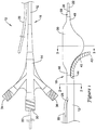
- the recanalization catheter 10 may include a main catheter shaft 12 extending from a hub assembly 14 at a proximal end 16 of the catheter shaft 12 to an expandable member, shown as an inflatable balloon 20 mounted on a distal portion of the catheter shaft 12 proximate the distal end 18 of the catheter shaft 12.
- an expandable member shown as an inflatable balloon 20 mounted on a distal portion of the catheter shaft 12 proximate the distal end 18 of the catheter shaft 12.
- the expandable member is illustrated as an inflatable balloon 20, in some embodiments the expandable member may be an expandable framework formed of one or more, or a plurality of struts which may be automatically or manually expanded, or other manually expandable or automatically expandable structure.
- the catheter 10 may be configured to be advanced over a guidewire 22 for delivery to a remote location in the vasculature of a patient.
- the catheter 10 may be configured as a single-operator-exchange (SOE) catheter having a guidewire lumen 24 extending from a distal port 26 to a proximal guidewire port 28 located a short distance proximal of the balloon 20 and distal of the hub assembly 14.
- SOE single-operator-exchange
- the guidewire 22 may extend through the guidewire lumen 24 between the distal port 26 and the proximal port 28, and extend along an exterior of the catheter shaft 12 proximal of the proximal port 28 to the proximal end 16 of the catheter shaft 12.
- the catheter 10 may be configured as an over-the-wire (OTW) catheter having a guidewire lumen 24 extending through the entire length of the catheter 10 from a distal port 26 at a distal tip of the catheter 10 to a proximal guidewire port 30 in the hub assembly 14.
- FIG. 1 illustrates such a configuration with the proximally extending portion of the guidewire 22 in dashed lines.
- the hub assembly 14 may not include a proximal guidewire port 30 and/or in instances in which the catheter 10 is an OTW catheter, the proximal guidewire port 28 may not be present.
- the catheter shaft 12 may also include an inflation lumen 32 extending from an inflation port 34 of the hub assembly 14 to an interior of the balloon 20.
- the inflation lumen 32 may be configured for delivering inflation fluid to the balloon 20 to inflate the balloon 20 during a medical procedure.
- the catheter 10 may also include a flexible tubular member 40 extending from the main catheter shaft 12 through opening 44.
- the opening 44 may be a side opening extending through a sidewall of a tubular member of the main catheter shaft 12, or the opening 44 may be a distal opening at the distal end of a tubular member of the main catheter shaft 12.
- the flexible tubular member 40 may extend along a portion of the exterior of the balloon 20, such that an exterior surface of the balloon 20 may engage the flexible tubular member 40 when the balloon 20 is inflated.
- the flexible tubular member 40 may extend from the main catheter shaft 12 at a location proximal of the balloon 20, and extend distally therefrom, such that the flexible tubular member 40 extends exterior of the proximal waist 46 of the balloon 20, which may be secured to a portion of the main catheter shaft 12.
- the distal tip 42 of the flexible tubular member 40 may terminate proximal of the distal waist 48 of the balloon 20, which may be secured to a portion of the main catheter shaft 12.
- the flexible tubular member 40 which may be considered a deflectable re-entry tube or redirection tube (e.g., a "stinger") in some instances, may include flexibility characteristics permitting the flexible tubular member 40 to be deflected away from the main catheter shaft 12 (e.g., away from the central longitudinal axis of the main catheter shaft 12) into a curved or deflected configuration.
- the flexible tubular member 40 may include one or more, or a plurality of cuts or slits formed through the sidewall of the flexible tubular member 40, providing the flexible tubular member 40 with a degree of lateral flexibility.
- the flexible tubular member 40 may include a helical cut or slit formed through the sidewall of the flexible tubular member 40 and extending along a length of the flexible tubular member 40, an arrangement of a plurality of cuts or slits formed through the sidewall of the flexible tubular member 40 and extending partially around the circumference of the flexible tubular member 40 along a length of the flexible tubular member 40, or another arrangement of cuts or slits formed in another fashion to provide a desired degree of lateral flexibility.
- the flexible tubular member 40 may be formed of a metallic material, including a stainless steel or a nickel-titanium alloy such as nitinol, a polymeric material such as polyamide, polyether block amide, polyethylene, or polyethylene terephthalate, or a combination of metallic and polymeric materials, for example.
- a metallic material including a stainless steel or a nickel-titanium alloy such as nitinol, a polymeric material such as polyamide, polyether block amide, polyethylene, or polyethylene terephthalate, or a combination of metallic and polymeric materials, for example.
- the flexible tubular member 40 may define a third, device delivery lumen 38 configured for delivering an elongated medical device to a target location via the catheter 10.
- the device delivery lumen 38 may extend from an access port 36 in the hub assembly 14 through the main catheter shaft 12 to the distal tip 42 of the flexible tubular member 40. Accordingly an elongated medical device may be inserted through the device delivery lumen 38 to be advanced from the distal tip 42 of the flexible tubular member 40 during a medical procedure.
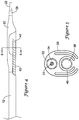
- the catheter shaft 12, or a portion thereof may include an outer tubular member 50, a first inner tubular member 52 extending through the outer tubular member 50, and a second inner tubular member 54 extending through the outer tubular member 50.
- the first inner tubular member 52 may define the guidewire lumen 24, and the second inner tubular member 54 may define the device delivery lumen 38.
- the second inner tubular member 54 may be an extension of the flexible tubular member 40 extending into the outer tubular member 50, or the second tubular member 54 may be secured to the flexible tubular member 40 and extend therefrom, providing the device delivery lumen 38 therein.
- the main catheter shaft 12 may be configured such that the proximal waist 46 of the balloon 20 is secured to the distal end of the outer tubular member 50, while the distal waist 48 of the balloon 20 is secured to the distal end of the first inner tubular member 52, extending through the interior of the balloon 20.
- the inflation lumen 32 may be defined between the outer tubular member 50 and the first and second inner tubular members 52, 54.
- the catheter shaft 12, or a portion thereof may be an extruded shaft 56 having a plurality of lumens formed therein.
- the extruded shaft 56 may include the guidewire lumen 24, the inflation lumen 32, and the device delivery lumen 38.
- the main catheter shaft 12 may be configured such that the proximal waist 46 of the balloon 20 is secured to a portion of the extruded shaft 56, while the distal waist 48 of the balloon 20 is secured to another portion of the extruded shaft 56 or a tubular member extending therefrom, extending through the interior of the balloon 20.
- the catheter 10 may also include a distal tip 58 extending distally from the balloon 20.
- the distal tip 58 may have a lumen extending therethrough and opening out to the distal port 26 at the distal end thereof to accommodate the guidewire 22 extending from the distal port 26.
- the distal tip 58 may be an atraumatic tip, such as a flexible, low durometer tip similar to tips provided with typical angioplasty balloon catheters.
- the distal tip 58 may be configured to facilitate piercing and/or dissection of tissue layers of the blood vessel.
- the distal tip 58 may include a sharp, rigid and/or piercing feature.
- the distal tip 58 may include an angled distal edge, providing the distal tip 58 with a sharpened cutting or piercing edge.
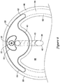
- FIG. 3 is a cross-sectional view of the catheter 10 taken through the balloon 20.
- the balloon 20 when inflated, may include a central bulbous portion 60, a first wing portion 62 extending from the bulbous portion 60 in a first direction, and a second wing portion 64 extending from the bulbous portion 60 is a second direction, generally opposite the first direction.
- the first and second wing portions 62, 64 may extend outwardly in opposing directions from the central bulbous portion 60.
- the balloon 20 may be formed of a non-distensible or stiffer material, such that when the balloon 20 is inflated, the balloon 20 maintains the bulbous portion 60 and wing portions 62, 64 shown in FIG. 3 .
- the winged portions 62, 64 may be configured to follow the curvature of a vessel wall, and thus generally orient the flexible tubular member 40 toward the center of the true lumen of the vessel during use. Furthermore, the bulbous portion 60 may be configured to contact and press against the flexible tubular member 40, thereby deflecting the flexible tubular member 40 upon inflation of the balloon 20.
- FIGS. 4 and 5 illustrate an exemplary arrangement of the catheter 10 with the balloon 20 deflated and in a delivery configuration.
- the deflated balloon 20 may be folded around the flexible tubular member 40 to provide the distal portion of the catheter 10 with a small delivery profile.
- the catheter 10 in the folded delivery configuration, may have an outer diameter of about 3 French (1 mm) to about 5 French (1.67 mm), for example about 3 French (1 mm), about 3.5 French (1.17 mm), about 4 French (1.33 mm), about 4.5 French (1.5 mm) or about 5 French (1.67 mm).
- the distal tip 42 of the flexible tubular member 40 may be wrapped within the folds of the balloon 20 to cover and protect the distal tip 42 from inadvertent contact with the vessel wall during delivery of the balloon 20 and flexible tubular member 40 to a target location in the vasculature.
- portions of balloon material forming the wings 62, 64 may be folded around the flexible tubular member 40 to maintain the flexible tubular member 40 in an elongated configuration generally parallel to the central longitudinal axis of the catheter shaft 12.
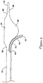
- FIG. 6 illustrates an alternative embodiment, in which the catheter 10 includes a pull wire 70, or other actuation mechanism to facilitate deflecting the flexible tubular member 40 into a curved configuration.
- the pull wire 70 may have a distal end secured to a distal portion of the flexible tubular member 40 proximate the distal tip 42 of the flexible tubular member 40.
- the pull wire 70 may extend to the proximal end of the catheter 10, or be attached to an actuatable component accessible at the proximal end of the catheter 10, to be manipulated by the operator to deflect the flexible tubular member 40 into a curved configuration.
- the flexible tubular member 40 may be configured to be curved or deflected from a generally axially aligned configuration A in which the flexible tubular member 40 extends along a central longitudinal axis Y generally parallel to the central longitudinal axis X of the main catheter shaft 12 to a curved configuration in which the distal portion of the flexible tubular member 40 is curved away from the longitudinal axis Y.
- the distal portion of the flexible tubular member 40 may be curved or deflected to a curved configuration B having an angle of curvature (i.e., arc angle) ⁇ 1 of less than 90°, for example about 30°, about 45°, or about 60°, in some instances.
- the distal portion of the flexible tubular member 40 may be curved or deflected to a curved configuration C having an angle of curvature (i.e., arc angle) ⁇ 2 of about 90°.
- the distal portion of the flexible tubular member 40 may be curved or deflected to a curved configuration D having an angle of curvature (i.e., arc angle) ⁇ 3 of greater than 90°, for example about 95° or more, about 100° or more, or about 105° or more in some instances.
- the "arc angle” or “angle of curvature” is intended to be the angle through which the distal portion of the flexible tubular member 40 curves through from the point along the longitudinal axis Y in which the flexible tubular member 40 begins to curve away from the longitudinal axis Y to the center of the opening at the distal tip 42 of the flexible tubular member 40.
- the opening of the lumen 38 at the distal tip 42 may face in a proximal direction in the curved configuration.
- the opening of the lumen 38 at the distal tip 42 may face in a proximal direction when the distal portion of the flexible tubular member 40 is deflected through an arc angle of 90° or more, 95° degrees or more, 100° degrees or more, or 105° degrees or more.
- an elongate medical device advanced out of the distal opening of the lumen 38 of the flexible tubular member 40 may be directed in a proximal or retrograde direction, for example.
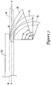
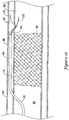
- FIG. 8 is a cross-sectional view of the distal portion of the catheter 10 positioned in a subintimal space created between two tissue layers of a vessel wall 80.
- the blood vessel 80 typically has three tissue layers, an innermost layer or intima layer (i.e., tunica intima) 82, an intermediate layer or media layer (i.e., tunica media) 84, and an outermost layer or adventitia layer (tunica adventitia) 86, with the media layer 84 positioned between the intima layer 80 and the adventitia layer 86.
- the intima layer 82 is a layer of endothelial cells lining the lumen 88 of the vessel 80, as well as a subendothelial layer made up of mostly loose connective tissue.
- the media layer 84 is a muscular layer formed primarily of circumferentially arranged smooth muscle cells.
- the adventitia layer 86, which forms the exterior layer of the vessel wall 80 is formed primarily of loose connective tissue made up of fibroblasts and associated collagen fibers.
- the distal portion of the catheter 10, including the balloon 20 may be advanced into a subintimal space (i.e., a space between the intima layer 82 and the adventitia layer 86) created in the vessel wall 80, such as through dissection of the tissue layers of the vessel wall 80.
- a subintimal space i.e., a space between the intima layer 82 and the adventitia layer 86
- the balloon 20 may be inflated between the intima layer 82 and the adventitia layer 86 of the vessel wall 80.
- the wings 62, 64 of the balloon 20 may be unfolded and inflated between the intima layer 82 and the adventitia layer 86 to orient the flexible tubular member 40 radially inward of the bulbous portion 60 of the balloon 20.
- the bulbous portion 60 of the balloon 20 may be inflated to press against the flexible tubular member 40 to deflect the flexible tubular member 40 toward the true lumen 88 of the vessel 80. Inflation of the bulbous portion 60 against the flexible tubular member 40 may cause the distal tip 42 of the flexible tubular member 40 to pierce through the intima layer 82 into the true lumen 88 to allow re-entry into the true lumen 88 with an elongate medical device advanced through the lumen 38.
- the forces generated through inflation of the balloon 20 may cause the internal intima layer 82 to yield first, bending or folding towards the true lumen 88, rather than causing the external adventitia layer 86 to stretch.
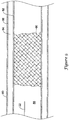
- FIGS. 9-14 several aspects of an exemplary method for recanalizing an occluded blood vessel using the catheter 10 are illustrated.
- a guidewire 22 may initially be advanced through the lumen 88 of the vessel 80 to a location proximate a proximal end of an occlusion 90 blocking the lumen 88.
- the guidewire 22 may then be advanced to penetrate outward through the intima layer 82 at a location proximal of the proximal end of the occlusion 90 into the vessel wall 80. With the tip of the guidewire 22 located between the intima layer 82 and the adventitia layer 86, the guidewire 22 may be further advanced distally in a subintimal manner to create a subintimal space between the intima layer 82 and the adventitia layer 86. As shown in FIG.
- the guidewire 22 may be advanced in a subintimal manner until the distal tip of the guidewire 22 is located distal of the distal end of the occlusion 90 in the subintimal space created, such as by dissection of the tissue layers of the vessel wall 80.
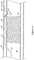
- the recanalization catheter 10 may then be advanced distally over the guidewire 22 from the true lumen 88 proximal of the occlusion 90, into the subintimal space between the intima layer 82 and the adventitia layer 86, to a position in the subintimal space in which the distal portion of the catheter 10, including the balloon 20, is located distal of the distal end of the occlusion 90, as shown in FIG. 11 .
- the recanalization catheter 10 may be advanced through the subintimal space in a delivery configuration, such as with the balloon 20 in a deflated, folded configuration wrapped around the flexible tubular member 40 extending from the main catheter shaft 12.
- the sharp, rigid or piercing feature of the distal tip 58 may be used to pierce and/or dissect tissue layers of the vessel wall 80 as the catheter 10 is advanced distally.
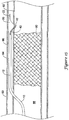
- the balloon 20 With the balloon 20 positioned distal of the distal end of the occlusion 90, the balloon 20 may be inflated in the subintimal space formed between the intima layer 82 and the adventitia layer 86, as shown in FIG. 12 .
- the wings 62, 64 of the balloon 20 may be unfolded and inflated between the intima layer 82 and the adventitia layer 86 to orient the flexible tubular member 40 radially inward of the bulbous portion 60 of the balloon 20.
- the bulbous portion 60 of the balloon 20 may be inflated to press against the flexible tubular member 40 to deflect the flexible tubular member 40 toward the true lumen 88 of the vessel 80.
- Inflation of the bulbous portion 60 against the flexible tubular member 40 may cause the distal tip 42 of the flexible tubular member 40 to pierce through the intima layer 82 and thus re-enter into the true lumen 88 to allow re-entry into the true lumen 88 distal of the occlusion 90 with an elongate medical device advanced through the lumen 38.
- the pull wire 70 may be actuated to facilitate and/or augment curving the flexible tubular member 40 into a curved configuration.
- the distal portion of the main catheter shaft 12, including the distal tip of the main catheter shaft 12 and the balloon 20, as well as the guidewire 22, may remain positioned in the subintimal space after the flexible tubular member 40 is deflected into the curved configuration and penetrates into the true lumen 88.
- the flexible tubular member 40 may be configured to be curved or deflected from a generally axially aligned configuration in which the flexible tubular member 40 extends parallel to the main catheter shaft 12 to a curved configuration in which the distal portion of the flexible tubular member 40 is curved away from the longitudinal axis of the main catheter shaft 12.
- the distal portion of the flexible tubular member 40 may be curved or deflected to a curved configuration having an angle of curvature (i.e., arc angle) of about 90° or greater than 90°, for example about 95° or more, about 100° or more, or about 105° or more in some instances.
- An elongate medical device 100 may then be advanced through the device delivery lumen 38 of the catheter 10 and exit the flexible tubular member 40 into the true lumen 88 distal of the occlusion 90 through the opening in the distal tip 42 of the flexible tubular member 40, shown in FIG. 13 .
- the flexible tubular member 40 may be curved such that the distal opening of the lumen 38 at the distal tip 42 of the flexible tubular member 40 faces in a proximal direction, and thus faces the distal end of the occlusion 90. Accordingly, the elongate medical device 100, upon exiting the flexible tubular member 40, may be directed or advanced proximally toward the distal end of the occlusion 90.
- the elongate medical device 100 is an occlusion crossing device, such as an atherectomy device, a needle-tipped catheter, a stylet or a guidewire
- the elongate medical device may be directed or advanced proximally from the distal opening of the lumen 38 of the flexible tubular member 40 toward the distal end of the occlusion 90 to penetrate into or through the occlusion 90 in a retrograde manner.
- the elongate medical device 100 may be an atherectomy device having an elongate shaft 104 with a distal cutting tip 102 attached thereto for penetrating into or through the occlusion 90.
- the distal cutting tip 102 may be a rotatable cutting tip or burr, such as a micro burr, expandable burr, an angled burr, an enhanced wire tip burr, a diamond coated burr, or other cutting device.
- the distal cutting tip 102 may be an ablation electrode or ultrasound transducer configured for ablating a pathway through the occlusion 90.
- the elongate medical device 100 may be advanced in a retrograde direction (i.e., proximally) into the distal end of the occlusion 90.
- the elongate medical device 100 may be advanced through the occlusion 90 from the distal end of the occlusion 90 to the proximal end of the occlusion 90 in a retrograde manner, as shown in FIG. 14 , to create a pathway through the occlusion 90 to recanalize the vessel and provide a pathway through the occlusion 90 for blood to flow therethrough.
- emboli created while boring or ablating through the occlusion 90 may flow distally away from the occlusion 90 as the atherectomy device is advanced through the occlusion 90.
- the balloon 20 may be inflated in the subintimal space formed between the intima layer 82 and the adventitia layer 86 to deflect the flexible tubular member 40 into a curved configuration by inflating the bulbous portion 60 of the balloon 20 against the flexible tubular member 40 to deflect the flexible tubular member 40 toward the true lumen 88 of the vessel 80.
- Inflation of the bulbous portion 60 against the flexible tubular member 40 may cause the distal tip 42 of the flexible tubular member 40 to pierce through the intima layer 82 and thus re-enter into the true lumen 88 to allow re-entry into the true lumen 88 distal of the occlusion 90 with an elongate medical device advanced through the lumen 38.
- the pull wire 70 may be actuated to facilitate and/or augment curving the flexible tubular member 40 into a curved configuration.
- the distal portion of the main catheter shaft 12, including the distal tip of the main catheter shaft 12 and the balloon 20, as well as the guidewire 22, may remain positioned in the subintimal space after the flexible tubular member 40 is deflected into the curved configuration and penetrates into the true lumen 88.
- inflation of the bulbous portion 60 against the flexible tubular member 40 may cause the distal tip 42 of the flexible tubular member 40 to be oriented toward the intima layer 82 and an elongate medical device, such as a guidewire, a stylet, a needle, or other device may be advanced through the flexible tubular member 40 to pierce through the intima layer 82 to re-enter into the true lumen 88 distal of the occlusion 90.
- an elongate medical device such as a guidewire, a stylet, a needle, or other device may be advanced through the flexible tubular member 40 to pierce through the intima layer 82 to re-enter into the true lumen 88 distal of the occlusion 90.
- the flexible tubular member 40 may be configured to be curved or deflected from a generally axially aligned configuration in which the flexible tubular member 40 extends parallel to the main catheter shaft 12 to a curved configuration in which the distal portion of the flexible tubular member 40 is curved away from the longitudinal axis of the main catheter shaft 12.
- the distal portion of the flexible tubular member 40 may be curved or deflected to a curved configuration having an angle of curvature (i.e., arc angle) of less than 90° such that the distal opening of the lumen 38 at the distal tip 42 of the flexible tubular member 40 faces in a distal direction.
- An elongate medical device 100 may then be advanced through the device delivery lumen 38 of the catheter 10 and exit the flexible tubular member 40 into the true lumen 88 distal of the occlusion 90 through the opening in the distal tip 42 of the flexible tubular member 40, shown in FIG. 16 .
- the flexible tubular member 40 may be curved such that the distal opening of the lumen 38 at the distal tip 42 of the flexible tubular member 40 faces in a distal direction, and thus faces away from the distal end of the occlusion 90. Accordingly, the elongate medical device 100, upon exiting the flexible tubular member 40, may be directed or advanced distally through the true lumen 88 away from the distal end of the occlusion 90.
- one or more additional medical devices may be advanced through the blood vessel 80 to enlarge the pathway and/or pass distally of the occlusion 90 to perform a further medical procedure.
Landscapes
- Health & Medical Sciences (AREA)
- Life Sciences & Earth Sciences (AREA)
- Surgery (AREA)
- Heart & Thoracic Surgery (AREA)
- Animal Behavior & Ethology (AREA)
- General Health & Medical Sciences (AREA)
- Biomedical Technology (AREA)
- Veterinary Medicine (AREA)
- Public Health (AREA)
- Engineering & Computer Science (AREA)
- Vascular Medicine (AREA)
- Molecular Biology (AREA)
- Medical Informatics (AREA)
- Nuclear Medicine, Radiotherapy & Molecular Imaging (AREA)
- Biophysics (AREA)
- Pulmonology (AREA)
- Anesthesiology (AREA)
- Hematology (AREA)
- Child & Adolescent Psychology (AREA)
- Orthopedic Medicine & Surgery (AREA)
- Media Introduction/Drainage Providing Device (AREA)
- Surgical Instruments (AREA)
Claims (14)
- Katheter (10) zum Rekanalisieren eines Blutgefäßes, das einen Verschluss darin hat, wobei der Katheter aufweist:einen Katheterschaft (12), der ein proximales Ende, ein distales Ende (18) und einen distalen Endabschnitt nahe dem distalen Ende aufweist;ein ausdehnbares Element, das an dem distalen Endabschnitt des Katheterschafts (12) befestigt ist; undein flexibles röhrenförmiges Element (40), das sich vom Katheterschaft (12) und längs eines Äußeren des ausdehnbaren Elements erstreckt;wobei eine Ausdehnung des ausdehnbaren Elements das flexible röhrenförmige Element weg von einer Längsachse des Katheterschafts (12) zu einer ausgelenkten Konfiguration auslenkt;wobei das ausdehnbare Element ein inflatierbarer Ballon (20) ist, der einen ersten Flügelabschnitt (62) und einen zweiten Flügelabschnitt (64) aufweist, die sich in entgegengesetzte Richtungen nach außen erstrecken und das flexible röhrenförmige Element zur Mitte des wahren Gefäßlumens hin ausrichten.
- Katheter nach Anspruch 1, wobei der erste und zweite Flügelabschnitt um das flexible röhrenförmige Element herum gefaltet sind, um das flexible röhrenförmige Element in einer länglichen Konfiguration im allgemeinen parallel zur Längsachse des Katheterschafts (12) in einer Zuführungskonfiguration zu halten.
- Katheter nach Anspruch 1, wobei der inflatierbare Ballon (20) einen bauchigen Abschnitt (60) aufweist, der zwischen dem ersten Flügelabschnitt (62) und dem zweiten Flügelabschnitt (64) angeordnet ist.
- Katheter nach Anspruch 3, wobei der bauchige Abschnitt (60) gegen das flexible röhrenförmige Element (40) inflatierbar ist, um das flexible röhrenförmige Element (40) zum wahren Lumen hin auszulenken.
- Katheter nach einem der vorhergehenden Ansprüche, wobei das flexible röhrenförmige Element (40) in eine gekrümmte Konfiguration von mindestens 90° auslenkbar ist.
- Katheter nach einem der vorhergehenden Ansprüche, wobei das flexible röhrenförmige Element (40) ein metallisches röhrenförmiges Element ist, das einen schraubenförmigen Schlitz aufweist, der sich dort hindurch erstreckt.
- Katheter nach Anspruch 6, wobei das metallische röhrenförmige Element eine abgewinkelte Spitze aufweist.
- Katheter nach einem der vorhergehenden Ansprüche, wobei das flexible röhrenförmige Element (40) eine distale Öffnung an einem distalen Ende des flexiblen röhrenförmigen Elements (40) aufweist, wobei die distale Öffnung in der ausgelenkten Konfiguration in eine proximale Richtung weist.
- Katheter nach einem der vorhergehenden Ansprüche, der ferner einen Zugdraht (70) mit einem distalen Ende aufweist, das an einem distalen Abschnitt des flexiblen röhrenförmigen Elements (40) befestigt ist.
- Katheter nach Anspruch 9, wobei sich der Zugdraht zu einem proximalen Ende des Katheters erstreckt.
- Katheter nach Anspruch 10, wobei der Zugdraht zum Auslenken des flexiblen röhrenförmigen Elements (40) handhabbar ist.
- Katheter nach einem der vorhergehenden Ansprüche, wobei der Katheterschaft (12) ein äußeres röhrenförmiges Element (50) und ein sich durch das äußere röhrenförmige Element erstreckendes inneres röhrenförmiges Element (52) aufweist.
- Katheter nach Anspruch 12, wobei eine proximale Taille (46) des Ballons (20) an einem distalen Ende des äußeren röhrenförmigen Elements befestigt ist und eine distale Taille (48) des Ballons (20) an einem distalen Ende des inneren röhrenförmigen Elements befestigt ist.
- Katheter nach Anspruch 13, wobei sich das innere röhrenförmige Element durch ein Inneres des Ballons (20) erstreckt.
Applications Claiming Priority (3)
| Application Number | Priority Date | Filing Date | Title |
|---|---|---|---|
| US201161536229P | 2011-09-19 | 2011-09-19 | |
| PCT/US2012/055905 WO2013043592A1 (en) | 2011-09-19 | 2012-09-18 | Subintimal re-entry catheter and retrograde recanalization |
| EP12777963.5A EP2757984B1 (de) | 2011-09-19 | 2012-09-18 | Subintimaler wiedereintrittskatheter und retrograde rekanalisation dafür |
Related Parent Applications (1)
| Application Number | Title | Priority Date | Filing Date |
|---|---|---|---|
| EP12777963.5A Division EP2757984B1 (de) | 2011-09-19 | 2012-09-18 | Subintimaler wiedereintrittskatheter und retrograde rekanalisation dafür |
Publications (2)
| Publication Number | Publication Date |
|---|---|
| EP3446649A1 EP3446649A1 (de) | 2019-02-27 |
| EP3446649B1 true EP3446649B1 (de) | 2020-05-20 |
Family
ID=47073496
Family Applications (2)
| Application Number | Title | Priority Date | Filing Date |
|---|---|---|---|
| EP18190670.2A Active EP3446649B1 (de) | 2011-09-19 | 2012-09-18 | Subintimaler wiedereintrittskatheter |
| EP12777963.5A Active EP2757984B1 (de) | 2011-09-19 | 2012-09-18 | Subintimaler wiedereintrittskatheter und retrograde rekanalisation dafür |
Family Applications After (1)
| Application Number | Title | Priority Date | Filing Date |
|---|---|---|---|
| EP12777963.5A Active EP2757984B1 (de) | 2011-09-19 | 2012-09-18 | Subintimaler wiedereintrittskatheter und retrograde rekanalisation dafür |
Country Status (6)
| Country | Link |
|---|---|
| US (3) | US9402981B2 (de) |
| EP (2) | EP3446649B1 (de) |
| JP (2) | JP6030655B2 (de) |
| AU (1) | AU2012312666B2 (de) |
| CA (1) | CA2848781C (de) |
| WO (1) | WO2013043592A1 (de) |
Families Citing this family (56)
| Publication number | Priority date | Publication date | Assignee | Title |
|---|---|---|---|---|
| US9511214B2 (en) | 2006-05-02 | 2016-12-06 | Vascular Access Technologies, Inc. | Methods of transvascular retrograde access placement and devices for facilitating therein |
| WO2008070189A2 (en) | 2006-12-06 | 2008-06-12 | The Cleveland Clinic Foundation | Method and system for treating acute heart failure by neuromodulation |
| WO2009042614A1 (en) * | 2007-09-26 | 2009-04-02 | Retro Vascular, Inc. | Recanalizing occluded vessels using radiofrequency energy |
| US9561073B2 (en) | 2007-09-26 | 2017-02-07 | Retrovascular, Inc. | Energy facilitated composition delivery |
| EP3446649B1 (de) * | 2011-09-19 | 2020-05-20 | Boston Scientific Scimed, Inc. | Subintimaler wiedereintrittskatheter |
| WO2013177394A1 (en) | 2012-05-24 | 2013-11-28 | Boston Scientific Scimed, Inc. | Subintimal re-entry device |
| US9623217B2 (en) | 2012-05-30 | 2017-04-18 | Vascular Access Techonlogies, Inc. | Transvascular access methods |
| WO2014012008A1 (en) | 2012-07-13 | 2014-01-16 | Boston Scientific Scimed, Inc. | Subintimal reentry system |
| US9456842B2 (en) * | 2012-07-13 | 2016-10-04 | Boston Scientific Scimed, Inc. | Wire-guided recanalization system |
| US9278192B2 (en) * | 2013-02-12 | 2016-03-08 | Invatec S.P.A. | Re-entry catheters and related methods |
| CN105228538B (zh) * | 2013-03-14 | 2018-04-24 | 波士顿科学国际有限公司 | 具有形状可控球囊的内膜下再进入导管 |
| US9878128B2 (en) * | 2013-03-14 | 2018-01-30 | Boston Scientific Scimed, Inc. | Systems, apparatus and methods for treating blood vessels |
| US9308356B2 (en) | 2013-07-29 | 2016-04-12 | Invatec S.P.A. | Occlusion bypassing apparatuses and methods for bypassing an occlusion in a blood vessel |
| US9301777B2 (en) | 2013-07-29 | 2016-04-05 | Invatec S.P.A. | Occlusion bypassing apparatuses and methods for bypassing an occlusion in a blood vessel |
| US9364642B2 (en) | 2013-08-14 | 2016-06-14 | Invatec S.P.A. | Balloon catheter systems and methods for bypassing an occlusion in a blood vessel |
| US9320874B2 (en) | 2013-08-15 | 2016-04-26 | Invatec S.P.A. | Catheter systems with a blocking mechanism and methods for bypassing an occlusion in a blood vessel |
| US9446222B2 (en) | 2014-03-05 | 2016-09-20 | Invatec S.P.A. | Catheter assemblies and methods for stabilizing a catheter assembly within a subintimal space |
| CA2946791C (en) | 2014-05-22 | 2023-09-19 | CARDIONOMIC, Inc. | Catheter and catheter system for electrical neuromodulation |
| US10098650B2 (en) * | 2014-06-09 | 2018-10-16 | Boston Scientific Scimed, Inc. | Systems and methods for treating atherosclerotic plaque |
| US10391282B2 (en) | 2014-07-08 | 2019-08-27 | Teleflex Innovations S.À.R.L. | Guidewires and methods for percutaneous occlusion crossing |
| US10456557B2 (en) | 2014-08-14 | 2019-10-29 | Invatec S.P.A. | Occlusion bypassing apparatus with varying flexibility and methods for bypassing an occlusion in a blood vessel |
| JP6651504B2 (ja) | 2014-08-21 | 2020-02-19 | コーニンクレッカ フィリップス エヌ ヴェKoninklijke Philips N.V. | 閉塞を横断するためのデバイス及び方法 |
| EP3194007B1 (de) * | 2014-09-08 | 2018-07-04 | Cardionomic, Inc. | Katheter und elektrodensysteme zur elektrischen neuromodulation |
| AU2015315570B2 (en) | 2014-09-08 | 2020-05-14 | CARDIONOMIC, Inc. | Methods for electrical neuromodulation of the heart |
| US10729454B2 (en) | 2014-09-10 | 2020-08-04 | Teleflex Life Sciences Limited | Guidewire capture |
| EP3194003B1 (de) * | 2014-09-15 | 2025-11-05 | Orbusneich Medical Pte. Ltd | Vaskulärer wiedereintrittskatheter |
| US10130384B2 (en) | 2014-09-23 | 2018-11-20 | CARDINAL HEALTH SWITZERLAND 515 GmbH | Catheter systems and methods for re-entry in body vessels with chronic total occlusion |
| CN109568786A (zh) | 2015-01-05 | 2019-04-05 | 卡迪诺米克公司 | 心脏调节促进方法及系统 |
| WO2016138004A1 (en) * | 2015-02-23 | 2016-09-01 | David Martini | Injection needle having varying caliber |
| EP3270999B1 (de) * | 2015-03-19 | 2022-12-07 | Boston Scientific Scimed, Inc. | Ballonkatheter für subintimalen wiedereintritt sowie herstellungsverfahren dafür |
| US10172632B2 (en) | 2015-09-22 | 2019-01-08 | Medtronic Vascular, Inc. | Occlusion bypassing apparatus with a re-entry needle and a stabilization tube |
| US10327791B2 (en) | 2015-10-07 | 2019-06-25 | Medtronic Vascular, Inc. | Occlusion bypassing apparatus with a re-entry needle and a distal stabilization balloon |
| CA3015372A1 (en) | 2016-03-09 | 2017-09-14 | CARDIONOMIC, Inc. | Cardiac contractility neurostimulation systems and methods |
| US10610669B2 (en) * | 2016-03-16 | 2020-04-07 | Krishna Rocha-Singh, M.D. | Apparatus and method for promoting angiogenesis in ischemic tissue |
| US10065018B2 (en) | 2016-03-16 | 2018-09-04 | Krishna Rocha-Singh | Apparatus and method for promoting angiogenesis in ischemic tissue |
| US10588637B2 (en) * | 2016-05-17 | 2020-03-17 | Cook Medical Technologies Llc | Temporary occlusion of blood vessel using extra-luminal balloon |
| US10245050B2 (en) * | 2016-09-30 | 2019-04-02 | Teleflex Innovations S.À.R.L. | Methods for facilitating revascularization of occlusion |
| US12053602B2 (en) * | 2016-12-09 | 2024-08-06 | Vascular Access Technologies, Inc. | Methods and devices for vascular access |
| US10617854B2 (en) * | 2016-12-09 | 2020-04-14 | Vascular Access Technologies, Inc. | Trans-jugular carotid artery access methods |
| US11654224B2 (en) | 2016-12-30 | 2023-05-23 | Vascular Access Technologies, Inc. | Methods and devices for percutaneous implantation of arterio-venous grafts |
| US11690645B2 (en) | 2017-05-03 | 2023-07-04 | Medtronic Vascular, Inc. | Tissue-removing catheter |
| EP3618734B1 (de) | 2017-05-03 | 2021-06-30 | Medtronic Vascular, Inc. | Gewebeentfernender katheter |
| WO2019046976A1 (en) * | 2017-09-11 | 2019-03-14 | Sunnybrook Research Institute | CATHETER DEVICE FOR LIGHT RE-INPUT AND METHODS OF USE |
| EP3664703A4 (de) | 2017-09-13 | 2021-05-12 | Cardionomic, Inc. | Neurostimulationssysteme und verfahren zur beeinflussung der herzkontraktilität |
| EP3700615B1 (de) | 2017-10-26 | 2022-08-24 | Teleflex Life Sciences Limited | Subintimalkathetervorrichtung und -anordnung |
| US10058684B1 (en) * | 2017-12-05 | 2018-08-28 | Justin Panian | Method and devices for passing a chronic total occlusion and re-entry into a true lumen |
| WO2019189826A1 (ja) * | 2018-03-29 | 2019-10-03 | 朝日インテック株式会社 | カテーテル、及び、再開通カテーテルシステム |
| EP3784143B8 (de) | 2018-04-24 | 2023-01-04 | Asahi Intecc Co., Ltd. | Wiedereintrittskatheter |
| WO2020036886A1 (en) | 2018-08-13 | 2020-02-20 | CARDIONOMIC, Inc. | Systems and methods for affecting cardiac contractility and/or relaxation |
| CN109045439B (zh) * | 2018-08-21 | 2020-08-14 | 业聚医疗器械(深圳)有限公司 | 一种导管系统 |
| CN118697424A (zh) | 2018-11-16 | 2024-09-27 | 美敦力瓦斯科尔勒公司 | 组织去除导管 |
| ES2993314T3 (en) * | 2019-04-05 | 2024-12-27 | Traverse Vascular Inc | Reentry catheters for traversing chronic total occlusions |
| SG11202111619WA (en) | 2019-05-06 | 2021-11-29 | Cardionomic Inc | Systems and methods for denoising physiological signals during electrical neuromodulation |
| US11819236B2 (en) | 2019-05-17 | 2023-11-21 | Medtronic Vascular, Inc. | Tissue-removing catheter |
| US20210260341A1 (en) * | 2020-02-20 | 2021-08-26 | Olympus Corporation | Method for collecting tissue in bile duct |
| US20230320571A1 (en) * | 2022-04-08 | 2023-10-12 | Olympus Medical Systems Corp. | Endoscope insertion method and overtube |
Family Cites Families (73)
| Publication number | Priority date | Publication date | Assignee | Title |
|---|---|---|---|---|
| US4878495A (en) * | 1987-05-15 | 1989-11-07 | Joseph Grayzel | Valvuloplasty device with satellite expansion means |
| GB8814898D0 (en) * | 1988-06-22 | 1988-07-27 | Evans J M | Catheters & methods of manufacture |
| US5141494A (en) * | 1990-02-15 | 1992-08-25 | Danforth Biomedical, Inc. | Variable wire diameter angioplasty dilatation balloon catheter |
| US5797960A (en) | 1993-02-22 | 1998-08-25 | Stevens; John H. | Method and apparatus for thoracoscopic intracardiac procedures |
| KR19990064209A (ko) | 1995-10-13 | 1999-07-26 | 트랜스바스큘라, 인코포레이티드 | 간질성 경혈관 개입을 위한 장치, 시스템 및 방법 |
| US6726677B1 (en) * | 1995-10-13 | 2004-04-27 | Transvascular, Inc. | Stabilized tissue penetrating catheters |
| EP1166721A3 (de) | 1995-10-13 | 2003-12-03 | Transvascular, Inc. | Vorrichtung für transvaskuläre Chirurgie |
| US5690642A (en) | 1996-01-18 | 1997-11-25 | Cook Incorporated | Rapid exchange stent delivery balloon catheter |
| US5916194A (en) * | 1996-05-24 | 1999-06-29 | Sarcos, Inc. | Catheter/guide wire steering apparatus and method |
| US6692483B2 (en) | 1996-11-04 | 2004-02-17 | Advanced Stent Technologies, Inc. | Catheter with attached flexible side sheath |
| US6010449A (en) | 1997-02-28 | 2000-01-04 | Lumend, Inc. | Intravascular catheter system for treating a vascular occlusion |
| US6120516A (en) | 1997-02-28 | 2000-09-19 | Lumend, Inc. | Method for treating vascular occlusion |
| US6508825B1 (en) | 1997-02-28 | 2003-01-21 | Lumend, Inc. | Apparatus for treating vascular occlusions |
| US5968064A (en) | 1997-02-28 | 1999-10-19 | Lumend, Inc. | Catheter system for treating a vascular occlusion |
| US6217549B1 (en) | 1997-02-28 | 2001-04-17 | Lumend, Inc. | Methods and apparatus for treating vascular occlusions |
| US5938671A (en) | 1997-11-14 | 1999-08-17 | Reflow, Inc. | Recanalization apparatus and devices for use therein and method |
| US5935108A (en) | 1997-11-14 | 1999-08-10 | Reflow, Inc. | Recanalization apparatus and devices for use therein and method |
| US6217527B1 (en) | 1998-09-30 | 2001-04-17 | Lumend, Inc. | Methods and apparatus for crossing vascular occlusions |
| US20050171478A1 (en) | 1998-01-13 | 2005-08-04 | Selmon Matthew R. | Catheter system for crossing total occlusions in vasculature |
| US6231546B1 (en) | 1998-01-13 | 2001-05-15 | Lumend, Inc. | Methods and apparatus for crossing total occlusions in blood vessels |
| US6241667B1 (en) | 1998-01-15 | 2001-06-05 | Lumend, Inc. | Catheter apparatus for guided transvascular treatment of arterial occlusions |
| US6398798B2 (en) | 1998-02-28 | 2002-06-04 | Lumend, Inc. | Catheter system for treating a vascular occlusion |
| US6475226B1 (en) * | 1999-02-03 | 2002-11-05 | Scimed Life Systems, Inc. | Percutaneous bypass apparatus and method |
| US20090093791A1 (en) | 1999-09-17 | 2009-04-09 | Heuser Richard R | Devices and methods for treating chronic total occlusion |
| US6506178B1 (en) | 2000-11-10 | 2003-01-14 | Vascular Architects, Inc. | Apparatus and method for crossing a position along a tubular body structure |
| WO2002045598A2 (en) | 2000-12-05 | 2002-06-13 | Lumend, Inc. | Catheter system for vascular re-entry from a sub-intimal space |
| US7740623B2 (en) | 2001-01-13 | 2010-06-22 | Medtronic, Inc. | Devices and methods for interstitial injection of biologic agents into tissue |
| US7357794B2 (en) | 2002-01-17 | 2008-04-15 | Medtronic Vascular, Inc. | Devices, systems and methods for acute or chronic delivery of substances or apparatus to extravascular treatment sites |
| US8214015B2 (en) | 2001-02-06 | 2012-07-03 | Medtronic Vascular, Inc. | In vivo localization and tracking of tissue penetrating catheters using magnetic resonance imaging |
| US6579302B2 (en) | 2001-03-06 | 2003-06-17 | Cordis Corporation | Total occlusion guidewire device |
| US6663577B2 (en) | 2001-12-07 | 2003-12-16 | Abbott Laboratories | Catheter deployment device |
| US20070219464A1 (en) * | 2002-03-22 | 2007-09-20 | Stephen Davis | Guidewire with deflectable re-entry tip |
| US20040102719A1 (en) | 2002-11-22 | 2004-05-27 | Velocimed, L.L.C. | Guide wire control catheters for crossing occlusions and related methods of use |
| US7008438B2 (en) * | 2003-07-14 | 2006-03-07 | Scimed Life Systems, Inc. | Anchored PTCA balloon |
| EP1786502A2 (de) | 2004-07-15 | 2007-05-23 | Incumed | Vorrichtung und verfahren zur behandlung eines blutgefässes |
| US7507256B2 (en) | 2004-12-17 | 2009-03-24 | Depuy Products, Inc. | Modular implant system and method with diaphyseal implant |
| WO2006084256A2 (en) | 2005-02-02 | 2006-08-10 | Peacock James C | Total vascular occlusion treatment system and method |
| CN101495171A (zh) | 2005-03-30 | 2009-07-29 | 卢门德公司 | 用于穿过脉管系统中的完全闭塞的导管系统 |
| US7200704B2 (en) | 2005-04-07 | 2007-04-03 | International Business Machines Corporation | Virtualization of an I/O adapter port using enablement and activation functions |
| JP5586147B2 (ja) | 2005-09-12 | 2014-09-10 | ブリッジポイント、メディカル、インコーポレイテッド | 壁内空間を活用するための脈管内デバイス |
| US7938819B2 (en) | 2005-09-12 | 2011-05-10 | Bridgepoint Medical, Inc. | Endovascular devices and methods |
| US7918870B2 (en) | 2005-09-12 | 2011-04-05 | Bridgepoint Medical, Inc. | Endovascular devices and methods |
| US8083727B2 (en) | 2005-09-12 | 2011-12-27 | Bridgepoint Medical, Inc. | Endovascular devices and methods for exploiting intramural space |
| WO2007055382A1 (ja) | 2005-11-14 | 2007-05-18 | Jms Co., Ltd. | 血流路拡張具及び大動脈解離用治療具 |
| EP3391934B1 (de) | 2006-02-13 | 2023-06-21 | RetroVascular, inc. | Rekanalisation verstopfter gefässe mit kontrollierter vorwärts- und rückwärtsverfolgung |
| US9119651B2 (en) | 2006-02-13 | 2015-09-01 | Retro Vascular, Inc. | Recanalizing occluded vessels using controlled antegrade and retrograde tracking |
| US8636715B2 (en) | 2006-09-25 | 2014-01-28 | Medtronic Vascular, Inc. | High torque, low profile catheters and methods for transluminal interventions |
| US8019404B2 (en) | 2006-10-06 | 2011-09-13 | The Cleveland Clinic Foundation | Apparatus and method for targeting a body tissue |
| WO2008063621A2 (en) | 2006-11-21 | 2008-05-29 | Bridgepoint Medical, Inc. | Endovascular devices and methods for exploiting intramural space |
| US10888354B2 (en) | 2006-11-21 | 2021-01-12 | Bridgepoint Medical, Inc. | Endovascular devices and methods for exploiting intramural space |
| US9060802B2 (en) | 2006-11-21 | 2015-06-23 | Bridgepoint Medical, Inc. | Endovascular devices and methods for exploiting intramural space |
| US20080154172A1 (en) | 2006-12-20 | 2008-06-26 | Medtronic Vascular, Inc. | Low Profile Catheters and Methods for Treatment of Chronic Total Occlusions and Other Disorders |
| US8257382B2 (en) | 2007-03-29 | 2012-09-04 | Boston Scientific Limited | Lumen reentry devices and methods |
| JP5453586B2 (ja) | 2007-10-22 | 2014-03-26 | ブリッジポイント、メディカル、インコーポレイテッド | 慢性的な完全閉塞部を横断するためのデバイスおよび方法 |
| US8337425B2 (en) | 2008-02-05 | 2012-12-25 | Bridgepoint Medical, Inc. | Endovascular device with a tissue piercing distal probe and associated methods |
| EP3251719B1 (de) | 2008-02-05 | 2020-10-21 | Bridgepoint Medical, Inc. | Durchqueren von okklusionen in blutgefässen |
| US8374680B2 (en) | 2008-04-21 | 2013-02-12 | Medtronic Vascular, Inc. | Needleless catheters and methods for true lumen re-entry in treatment of chronic total occlusions and other disorders |
| EP4545025A1 (de) | 2008-04-28 | 2025-04-30 | Boston Scientific Scimed Inc. | Verfahren und vorrichtung zum durchqueren von occlussionen in blutgefässen |
| WO2009141822A1 (en) | 2008-05-21 | 2009-11-26 | The Medical Research, Infrastructure, And Health Services Fund Of The Tel Aviv Medical Center | A device and method for crossing occlusions |
| US9775632B2 (en) | 2008-05-23 | 2017-10-03 | Medinol Ltd. | Method and device for recanalization of total occlusions |
| US20090299171A1 (en) | 2008-06-03 | 2009-12-03 | Medtronic Vascular, Inc. | Intraluminal Access and Imaging Device |
| US8150169B2 (en) | 2008-09-16 | 2012-04-03 | Viewdle Inc. | System and method for object clustering and identification in video |
| US8021330B2 (en) | 2008-11-14 | 2011-09-20 | Medtronic Vascular, Inc. | Balloon catheter for crossing a chronic total occlusion |
| US8226566B2 (en) | 2009-06-12 | 2012-07-24 | Flowcardia, Inc. | Device and method for vascular re-entry |
| US20120265233A1 (en) * | 2009-08-28 | 2012-10-18 | Lea Waisman | Inverted balloon neck on catheter |
| WO2011028632A1 (en) * | 2009-09-03 | 2011-03-10 | Si Therapies Ltd. | Lancet micro-catheter |
| US8372055B2 (en) * | 2009-10-27 | 2013-02-12 | Medtronic, Inc. | Method of using a deflectable subselecting catheter |
| US8241311B2 (en) | 2009-12-15 | 2012-08-14 | Medtronic Vascular, Inc. | Methods and systems for bypassing an occlusion in a blood vessel |
| CA2784499C (en) * | 2009-12-15 | 2017-04-18 | Edwards Lifesciences Corporation | Expansion device for treatment of vascular passageways |
| US9814862B2 (en) | 2011-06-30 | 2017-11-14 | The Spectranetics Corporation | Reentry catheter and method thereof |
| US8998936B2 (en) | 2011-06-30 | 2015-04-07 | The Spectranetics Corporation | Reentry catheter and method thereof |
| US8956376B2 (en) | 2011-06-30 | 2015-02-17 | The Spectranetics Corporation | Reentry catheter and method thereof |
| EP3446649B1 (de) * | 2011-09-19 | 2020-05-20 | Boston Scientific Scimed, Inc. | Subintimaler wiedereintrittskatheter |
-
2012
- 2012-09-18 EP EP18190670.2A patent/EP3446649B1/de active Active
- 2012-09-18 AU AU2012312666A patent/AU2012312666B2/en not_active Ceased
- 2012-09-18 JP JP2014530946A patent/JP6030655B2/ja active Active
- 2012-09-18 US US13/622,128 patent/US9402981B2/en active Active
- 2012-09-18 WO PCT/US2012/055905 patent/WO2013043592A1/en not_active Ceased
- 2012-09-18 EP EP12777963.5A patent/EP2757984B1/de active Active
- 2012-09-18 CA CA2848781A patent/CA2848781C/en not_active Expired - Fee Related
-
2016
- 2016-06-28 US US15/195,293 patent/US10149689B2/en active Active
- 2016-07-07 JP JP2016134828A patent/JP6408517B2/ja active Active
-
2018
- 2018-11-06 US US16/181,586 patent/US11033286B2/en active Active
Non-Patent Citations (1)
| Title |
|---|
| None * |
Also Published As
| Publication number | Publication date |
|---|---|
| CA2848781C (en) | 2018-10-23 |
| US10149689B2 (en) | 2018-12-11 |
| JP6408517B2 (ja) | 2018-10-17 |
| JP2014526347A (ja) | 2014-10-06 |
| AU2012312666B2 (en) | 2016-09-15 |
| WO2013043592A1 (en) | 2013-03-28 |
| US20160302807A1 (en) | 2016-10-20 |
| JP2016187616A (ja) | 2016-11-04 |
| CA2848781A1 (en) | 2013-03-28 |
| US20190069914A1 (en) | 2019-03-07 |
| EP2757984A1 (de) | 2014-07-30 |
| EP3446649A1 (de) | 2019-02-27 |
| US9402981B2 (en) | 2016-08-02 |
| JP6030655B2 (ja) | 2016-11-24 |
| US11033286B2 (en) | 2021-06-15 |
| US20130072957A1 (en) | 2013-03-21 |
| AU2012312666A1 (en) | 2014-04-17 |
| EP2757984B1 (de) | 2018-08-29 |
Similar Documents
| Publication | Publication Date | Title |
|---|---|---|
| US11033286B2 (en) | Subintimal re-entry catheter and retrograde recanalization | |
| EP3270999B1 (de) | Ballonkatheter für subintimalen wiedereintritt sowie herstellungsverfahren dafür | |
| EP2872209B1 (de) | Subintimaler re-entry-system | |
| EP2967637B1 (de) | Subintimaler wiedereintrittskatheter mit formkontrolliertem ballon | |
| US10117659B2 (en) | Subintimal re-entry catheter with actuatable orientation mechanism | |
| EP3903701B1 (de) | Endovaskuläre vorrichtung mit einer gewebedurchdringenden distalen sonde | |
| US9486239B2 (en) | Subintimal re-entry device | |
| EP2777744B1 (de) | Katheter mit Nadeln zur Ablation von Gewebeschichten in einem Gefäß | |
| US20140277009A1 (en) | Device and Method for Treating a Chronic Total Occlusion | |
| WO2014158866A1 (en) | Device and method for treating a chronic total occlusion | |
| US20240299712A1 (en) | Subintimal re-entry catheter with intravascular ultrasound capabilities |
Legal Events
| Date | Code | Title | Description |
|---|---|---|---|
| PUAI | Public reference made under article 153(3) epc to a published international application that has entered the european phase |
Free format text: ORIGINAL CODE: 0009012 |
|
| STAA | Information on the status of an ep patent application or granted ep patent |
Free format text: STATUS: REQUEST FOR EXAMINATION WAS MADE |
|
| 17P | Request for examination filed |
Effective date: 20180924 |
|
| AC | Divisional application: reference to earlier application |
Ref document number: 2757984 Country of ref document: EP Kind code of ref document: P |
|
| AK | Designated contracting states |
Kind code of ref document: A1 Designated state(s): AL AT BE BG CH CY CZ DE DK EE ES FI FR GB GR HR HU IE IS IT LI LT LU LV MC MK MT NL NO PL PT RO RS SE SI SK SM TR |
|
| GRAP | Despatch of communication of intention to grant a patent |
Free format text: ORIGINAL CODE: EPIDOSNIGR1 |
|
| STAA | Information on the status of an ep patent application or granted ep patent |
Free format text: STATUS: GRANT OF PATENT IS INTENDED |
|
| INTG | Intention to grant announced |
Effective date: 20191202 |
|
| GRAS | Grant fee paid |
Free format text: ORIGINAL CODE: EPIDOSNIGR3 |
|
| GRAA | (expected) grant |
Free format text: ORIGINAL CODE: 0009210 |
|
| STAA | Information on the status of an ep patent application or granted ep patent |
Free format text: STATUS: THE PATENT HAS BEEN GRANTED |
|
| AC | Divisional application: reference to earlier application |
Ref document number: 2757984 Country of ref document: EP Kind code of ref document: P |
|
| AK | Designated contracting states |
Kind code of ref document: B1 Designated state(s): AL AT BE BG CH CY CZ DE DK EE ES FI FR GB GR HR HU IE IS IT LI LT LU LV MC MK MT NL NO PL PT RO RS SE SI SK SM TR |
|
| REG | Reference to a national code |
Ref country code: GB Ref legal event code: FG4D |
|
| REG | Reference to a national code |
Ref country code: CH Ref legal event code: EP |
|
| REG | Reference to a national code |
Ref country code: DE Ref legal event code: R096 Ref document number: 602012070287 Country of ref document: DE |
|
| REG | Reference to a national code |
Ref country code: AT Ref legal event code: REF Ref document number: 1272095 Country of ref document: AT Kind code of ref document: T Effective date: 20200615 |
|
| REG | Reference to a national code |
Ref country code: NL Ref legal event code: FP |
|
| REG | Reference to a national code |
Ref country code: LT Ref legal event code: MG4D |
|
| PG25 | Lapsed in a contracting state [announced via postgrant information from national office to epo] |
Ref country code: GR Free format text: LAPSE BECAUSE OF FAILURE TO SUBMIT A TRANSLATION OF THE DESCRIPTION OR TO PAY THE FEE WITHIN THE PRESCRIBED TIME-LIMIT Effective date: 20200821 Ref country code: FI Free format text: LAPSE BECAUSE OF FAILURE TO SUBMIT A TRANSLATION OF THE DESCRIPTION OR TO PAY THE FEE WITHIN THE PRESCRIBED TIME-LIMIT Effective date: 20200520 Ref country code: IS Free format text: LAPSE BECAUSE OF FAILURE TO SUBMIT A TRANSLATION OF THE DESCRIPTION OR TO PAY THE FEE WITHIN THE PRESCRIBED TIME-LIMIT Effective date: 20200920 Ref country code: NO Free format text: LAPSE BECAUSE OF FAILURE TO SUBMIT A TRANSLATION OF THE DESCRIPTION OR TO PAY THE FEE WITHIN THE PRESCRIBED TIME-LIMIT Effective date: 20200820 Ref country code: LT Free format text: LAPSE BECAUSE OF FAILURE TO SUBMIT A TRANSLATION OF THE DESCRIPTION OR TO PAY THE FEE WITHIN THE PRESCRIBED TIME-LIMIT Effective date: 20200520 Ref country code: SE Free format text: LAPSE BECAUSE OF FAILURE TO SUBMIT A TRANSLATION OF THE DESCRIPTION OR TO PAY THE FEE WITHIN THE PRESCRIBED TIME-LIMIT Effective date: 20200520 Ref country code: PT Free format text: LAPSE BECAUSE OF FAILURE TO SUBMIT A TRANSLATION OF THE DESCRIPTION OR TO PAY THE FEE WITHIN THE PRESCRIBED TIME-LIMIT Effective date: 20200921 |
|
| PG25 | Lapsed in a contracting state [announced via postgrant information from national office to epo] |
Ref country code: HR Free format text: LAPSE BECAUSE OF FAILURE TO SUBMIT A TRANSLATION OF THE DESCRIPTION OR TO PAY THE FEE WITHIN THE PRESCRIBED TIME-LIMIT Effective date: 20200520 Ref country code: LV Free format text: LAPSE BECAUSE OF FAILURE TO SUBMIT A TRANSLATION OF THE DESCRIPTION OR TO PAY THE FEE WITHIN THE PRESCRIBED TIME-LIMIT Effective date: 20200520 Ref country code: RS Free format text: LAPSE BECAUSE OF FAILURE TO SUBMIT A TRANSLATION OF THE DESCRIPTION OR TO PAY THE FEE WITHIN THE PRESCRIBED TIME-LIMIT Effective date: 20200520 Ref country code: BG Free format text: LAPSE BECAUSE OF FAILURE TO SUBMIT A TRANSLATION OF THE DESCRIPTION OR TO PAY THE FEE WITHIN THE PRESCRIBED TIME-LIMIT Effective date: 20200820 |
|
| REG | Reference to a national code |
Ref country code: AT Ref legal event code: MK05 Ref document number: 1272095 Country of ref document: AT Kind code of ref document: T Effective date: 20200520 |
|
| PG25 | Lapsed in a contracting state [announced via postgrant information from national office to epo] |
Ref country code: AL Free format text: LAPSE BECAUSE OF FAILURE TO SUBMIT A TRANSLATION OF THE DESCRIPTION OR TO PAY THE FEE WITHIN THE PRESCRIBED TIME-LIMIT Effective date: 20200520 |
|
| PG25 | Lapsed in a contracting state [announced via postgrant information from national office to epo] |
Ref country code: ES Free format text: LAPSE BECAUSE OF FAILURE TO SUBMIT A TRANSLATION OF THE DESCRIPTION OR TO PAY THE FEE WITHIN THE PRESCRIBED TIME-LIMIT Effective date: 20200520 Ref country code: CZ Free format text: LAPSE BECAUSE OF FAILURE TO SUBMIT A TRANSLATION OF THE DESCRIPTION OR TO PAY THE FEE WITHIN THE PRESCRIBED TIME-LIMIT Effective date: 20200520 Ref country code: RO Free format text: LAPSE BECAUSE OF FAILURE TO SUBMIT A TRANSLATION OF THE DESCRIPTION OR TO PAY THE FEE WITHIN THE PRESCRIBED TIME-LIMIT Effective date: 20200520 Ref country code: EE Free format text: LAPSE BECAUSE OF FAILURE TO SUBMIT A TRANSLATION OF THE DESCRIPTION OR TO PAY THE FEE WITHIN THE PRESCRIBED TIME-LIMIT Effective date: 20200520 Ref country code: AT Free format text: LAPSE BECAUSE OF FAILURE TO SUBMIT A TRANSLATION OF THE DESCRIPTION OR TO PAY THE FEE WITHIN THE PRESCRIBED TIME-LIMIT Effective date: 20200520 Ref country code: DK Free format text: LAPSE BECAUSE OF FAILURE TO SUBMIT A TRANSLATION OF THE DESCRIPTION OR TO PAY THE FEE WITHIN THE PRESCRIBED TIME-LIMIT Effective date: 20200520 Ref country code: IT Free format text: LAPSE BECAUSE OF FAILURE TO SUBMIT A TRANSLATION OF THE DESCRIPTION OR TO PAY THE FEE WITHIN THE PRESCRIBED TIME-LIMIT Effective date: 20200520 Ref country code: SM Free format text: LAPSE BECAUSE OF FAILURE TO SUBMIT A TRANSLATION OF THE DESCRIPTION OR TO PAY THE FEE WITHIN THE PRESCRIBED TIME-LIMIT Effective date: 20200520 |
|
| REG | Reference to a national code |
Ref country code: DE Ref legal event code: R097 Ref document number: 602012070287 Country of ref document: DE |
|
| PG25 | Lapsed in a contracting state [announced via postgrant information from national office to epo] |
Ref country code: PL Free format text: LAPSE BECAUSE OF FAILURE TO SUBMIT A TRANSLATION OF THE DESCRIPTION OR TO PAY THE FEE WITHIN THE PRESCRIBED TIME-LIMIT Effective date: 20200520 Ref country code: SK Free format text: LAPSE BECAUSE OF FAILURE TO SUBMIT A TRANSLATION OF THE DESCRIPTION OR TO PAY THE FEE WITHIN THE PRESCRIBED TIME-LIMIT Effective date: 20200520 |
|
| PLBE | No opposition filed within time limit |
Free format text: ORIGINAL CODE: 0009261 |
|
| STAA | Information on the status of an ep patent application or granted ep patent |
Free format text: STATUS: NO OPPOSITION FILED WITHIN TIME LIMIT |
|
| 26N | No opposition filed |
Effective date: 20210223 |
|
| REG | Reference to a national code |
Ref country code: CH Ref legal event code: PL |
|
| GBPC | Gb: european patent ceased through non-payment of renewal fee |
Effective date: 20200918 |
|
| PG25 | Lapsed in a contracting state [announced via postgrant information from national office to epo] |
Ref country code: SI Free format text: LAPSE BECAUSE OF FAILURE TO SUBMIT A TRANSLATION OF THE DESCRIPTION OR TO PAY THE FEE WITHIN THE PRESCRIBED TIME-LIMIT Effective date: 20200520 |
|
| REG | Reference to a national code |
Ref country code: BE Ref legal event code: MM Effective date: 20200930 |
|
| PG25 | Lapsed in a contracting state [announced via postgrant information from national office to epo] |
Ref country code: LU Free format text: LAPSE BECAUSE OF NON-PAYMENT OF DUE FEES Effective date: 20200918 |
|
| PG25 | Lapsed in a contracting state [announced via postgrant information from national office to epo] |
Ref country code: FR Free format text: LAPSE BECAUSE OF NON-PAYMENT OF DUE FEES Effective date: 20200930 |
|
| PG25 | Lapsed in a contracting state [announced via postgrant information from national office to epo] |
Ref country code: LI Free format text: LAPSE BECAUSE OF NON-PAYMENT OF DUE FEES Effective date: 20200930 Ref country code: BE Free format text: LAPSE BECAUSE OF NON-PAYMENT OF DUE FEES Effective date: 20200930 Ref country code: CH Free format text: LAPSE BECAUSE OF NON-PAYMENT OF DUE FEES Effective date: 20200930 Ref country code: GB Free format text: LAPSE BECAUSE OF NON-PAYMENT OF DUE FEES Effective date: 20200918 |
|
| PG25 | Lapsed in a contracting state [announced via postgrant information from national office to epo] |
Ref country code: TR Free format text: LAPSE BECAUSE OF FAILURE TO SUBMIT A TRANSLATION OF THE DESCRIPTION OR TO PAY THE FEE WITHIN THE PRESCRIBED TIME-LIMIT Effective date: 20200520 Ref country code: MT Free format text: LAPSE BECAUSE OF FAILURE TO SUBMIT A TRANSLATION OF THE DESCRIPTION OR TO PAY THE FEE WITHIN THE PRESCRIBED TIME-LIMIT Effective date: 20200520 Ref country code: CY Free format text: LAPSE BECAUSE OF FAILURE TO SUBMIT A TRANSLATION OF THE DESCRIPTION OR TO PAY THE FEE WITHIN THE PRESCRIBED TIME-LIMIT Effective date: 20200520 |
|
| PG25 | Lapsed in a contracting state [announced via postgrant information from national office to epo] |
Ref country code: MK Free format text: LAPSE BECAUSE OF FAILURE TO SUBMIT A TRANSLATION OF THE DESCRIPTION OR TO PAY THE FEE WITHIN THE PRESCRIBED TIME-LIMIT Effective date: 20200520 Ref country code: MC Free format text: LAPSE BECAUSE OF FAILURE TO SUBMIT A TRANSLATION OF THE DESCRIPTION OR TO PAY THE FEE WITHIN THE PRESCRIBED TIME-LIMIT Effective date: 20200520 |
|
| PGFP | Annual fee paid to national office [announced via postgrant information from national office to epo] |
Ref country code: NL Payment date: 20250820 Year of fee payment: 14 |
|
| PGFP | Annual fee paid to national office [announced via postgrant information from national office to epo] |
Ref country code: DE Payment date: 20250820 Year of fee payment: 14 |
|
| PGFP | Annual fee paid to national office [announced via postgrant information from national office to epo] |
Ref country code: IE Payment date: 20250822 Year of fee payment: 14 |