EP3446587A1 - Tread pattern for article of footwear - Google Patents
Tread pattern for article of footwear Download PDFInfo
- Publication number
- EP3446587A1 EP3446587A1 EP18200599.1A EP18200599A EP3446587A1 EP 3446587 A1 EP3446587 A1 EP 3446587A1 EP 18200599 A EP18200599 A EP 18200599A EP 3446587 A1 EP3446587 A1 EP 3446587A1
- Authority
- EP
- European Patent Office
- Prior art keywords
- ground engaging
- engaging members
- footwear
- sole
- article
- Prior art date
- Legal status (The legal status is an assumption and is not a legal conclusion. Google has not performed a legal analysis and makes no representation as to the accuracy of the status listed.)
- Granted
Links
Images


Classifications
-
- A—HUMAN NECESSITIES
- A43—FOOTWEAR
- A43B—CHARACTERISTIC FEATURES OF FOOTWEAR; PARTS OF FOOTWEAR
- A43B13/00—Soles; Sole-and-heel integral units
- A43B13/14—Soles; Sole-and-heel integral units characterised by the constructive form
- A43B13/141—Soles; Sole-and-heel integral units characterised by the constructive form with a part of the sole being flexible, e.g. permitting articulation or torsion
-
- A—HUMAN NECESSITIES
- A43—FOOTWEAR
- A43B—CHARACTERISTIC FEATURES OF FOOTWEAR; PARTS OF FOOTWEAR
- A43B13/00—Soles; Sole-and-heel integral units
- A43B13/02—Soles; Sole-and-heel integral units characterised by the material
- A43B13/026—Composites, e.g. carbon fibre or aramid fibre; the sole, one or more sole layers or sole part being made of a composite
-
- A—HUMAN NECESSITIES
- A43—FOOTWEAR
- A43B—CHARACTERISTIC FEATURES OF FOOTWEAR; PARTS OF FOOTWEAR
- A43B13/00—Soles; Sole-and-heel integral units
- A43B13/02—Soles; Sole-and-heel integral units characterised by the material
- A43B13/04—Plastics, rubber or vulcanised fibre
-
- A—HUMAN NECESSITIES
- A43—FOOTWEAR
- A43B—CHARACTERISTIC FEATURES OF FOOTWEAR; PARTS OF FOOTWEAR
- A43B13/00—Soles; Sole-and-heel integral units
- A43B13/02—Soles; Sole-and-heel integral units characterised by the material
- A43B13/12—Soles with several layers of different materials
- A43B13/122—Soles with several layers of different materials characterised by the outsole or external layer
-
- A—HUMAN NECESSITIES
- A43—FOOTWEAR
- A43B—CHARACTERISTIC FEATURES OF FOOTWEAR; PARTS OF FOOTWEAR
- A43B13/00—Soles; Sole-and-heel integral units
- A43B13/02—Soles; Sole-and-heel integral units characterised by the material
- A43B13/12—Soles with several layers of different materials
- A43B13/125—Soles with several layers of different materials characterised by the midsole or middle layer
-
- A—HUMAN NECESSITIES
- A43—FOOTWEAR
- A43B—CHARACTERISTIC FEATURES OF FOOTWEAR; PARTS OF FOOTWEAR
- A43B13/00—Soles; Sole-and-heel integral units
- A43B13/14—Soles; Sole-and-heel integral units characterised by the constructive form
-
- A—HUMAN NECESSITIES
- A43—FOOTWEAR
- A43B—CHARACTERISTIC FEATURES OF FOOTWEAR; PARTS OF FOOTWEAR
- A43B13/00—Soles; Sole-and-heel integral units
- A43B13/14—Soles; Sole-and-heel integral units characterised by the constructive form
- A43B13/18—Resilient soles
- A43B13/181—Resiliency achieved by the structure of the sole
-
- A—HUMAN NECESSITIES
- A43—FOOTWEAR
- A43B—CHARACTERISTIC FEATURES OF FOOTWEAR; PARTS OF FOOTWEAR
- A43B13/00—Soles; Sole-and-heel integral units
- A43B13/14—Soles; Sole-and-heel integral units characterised by the constructive form
- A43B13/18—Resilient soles
- A43B13/187—Resiliency achieved by the features of the material, e.g. foam, non liquid materials
-
- A—HUMAN NECESSITIES
- A43—FOOTWEAR
- A43B—CHARACTERISTIC FEATURES OF FOOTWEAR; PARTS OF FOOTWEAR
- A43B13/00—Soles; Sole-and-heel integral units
- A43B13/14—Soles; Sole-and-heel integral units characterised by the constructive form
- A43B13/22—Soles made slip-preventing or wear-resisting, e.g. by impregnation or spreading a wear-resisting layer
-
- A—HUMAN NECESSITIES
- A43—FOOTWEAR
- A43B—CHARACTERISTIC FEATURES OF FOOTWEAR; PARTS OF FOOTWEAR
- A43B13/00—Soles; Sole-and-heel integral units
- A43B13/14—Soles; Sole-and-heel integral units characterised by the constructive form
- A43B13/22—Soles made slip-preventing or wear-resisting, e.g. by impregnation or spreading a wear-resisting layer
- A43B13/223—Profiled soles
-
- A—HUMAN NECESSITIES
- A43—FOOTWEAR
- A43B—CHARACTERISTIC FEATURES OF FOOTWEAR; PARTS OF FOOTWEAR
- A43B13/00—Soles; Sole-and-heel integral units
- A43B13/14—Soles; Sole-and-heel integral units characterised by the constructive form
- A43B13/22—Soles made slip-preventing or wear-resisting, e.g. by impregnation or spreading a wear-resisting layer
- A43B13/24—Soles made slip-preventing or wear-resisting, e.g. by impregnation or spreading a wear-resisting layer by use of insertions
- A43B13/26—Soles made slip-preventing or wear-resisting, e.g. by impregnation or spreading a wear-resisting layer by use of insertions projecting beyond the sole surface
-
- A—HUMAN NECESSITIES
- A43—FOOTWEAR
- A43C—FASTENINGS OR ATTACHMENTS OF FOOTWEAR; LACES IN GENERAL
- A43C15/00—Non-skid devices or attachments
- A43C15/16—Studs or cleats for football or like boots
- A43C15/161—Studs or cleats for football or like boots characterised by the attachment to the sole
-
- A—HUMAN NECESSITIES
- A43—FOOTWEAR
- A43C—FASTENINGS OR ATTACHMENTS OF FOOTWEAR; LACES IN GENERAL
- A43C15/00—Non-skid devices or attachments
- A43C15/16—Studs or cleats for football or like boots
- A43C15/162—Studs or cleats for football or like boots characterised by the shape
- A43C15/164—Studs or cleats for football or like boots characterised by the shape having a circular cross section
- A43C15/165—Studs or cleats for football or like boots characterised by the shape having a circular cross section pointed or conical, e.g. calks, spikes, pins
Definitions
- the present invention relates generally to a tread pattern for an article of footwear. It is advantageous, when participating in various activities, to have footwear that provides traction and stability on the surface upon which the activities take place. Accordingly, sole structures for articles of footwear have been developed with traction systems that include ground engaging members to provide traction on a variety of surfaces. Examples include cleated shoes developed for outdoor sports, such as soccer, football, and baseball.
- the present disclosure is directed to an article of footwear, including a sole having a lower surface exposed to the ground.
- the article of footwear may include a forefoot region having a first forefoot section and a second forefoot section separated by a first flex groove.
- the first flex groove may be formed by an upwardly extending elongate recess in the lower surface of the sole.
- the first forefoot section may include a first set of ground engaging members extending substantially downward from the lower surface of the sole, the first set of ground engaging members forming a substantially arcuate first arrangement.
- the second forefoot section may include a second set of ground engaging members extending substantially downward from the lower surface of the sole, the second set of ground engaging members forming a substantially arcuate second arrangement.
- the first arrangement may be curved in a different direction than the second arrangement.
- each ground engaging member of the first set of ground engaging members may have a length extending along an arc.
- the present disclosure is directed to an article of footwear including a ground engaging sole.
- the ground engaging sole may include a lower surface exposed to the ground and divided, in a forefoot region of the article of footwear, into a first forefoot section and a second forefoot section by a first flex groove formed by an upwardly extending elongate recess in the lower surface of the sole.
- the first forefoot section may include a first set of ground engaging members extending substantially downward from the lower surface of the sole, the first set of ground engaging members forming a substantially arcuate first arrangement.
- the second forefoot section may include a second set of ground engaging members extending substantially downward from the lower surface of the sole, the second set of ground engaging members forming a substantially arcuate second arrangement curved in a different direction than the arcuate arrangement of the first set of ground engaging members.
- the first set of ground engaging members may include two or more rows of ground engaging members having substantially the same shape and the second set of ground engaging members includes two or more rows of ground engaging members having substantially the same shape.
- the first set of ground engaging members may each have a first shape and the second set of ground engaging members may each have a second shape substantially different from the first shape.
- the present disclosure is directed to an article of footwear including a sole.
- the sole may include a lower surface exposed to the ground.
- the lower surface may include a first forefoot section separated from a second forefoot section by a first flex groove formed by an upwardly extending elongate recess in the lower surface of the sole.
- the lower surface may include a third forefoot section separated from the second forefoot section by a second flex groove formed by an upwardly extending elongate recess in the lower surface of the sole.
- the first forefoot section may include a first set of ground engaging members extending substantially downward from the lower surface of the sole, the first set of ground engaging members forming a substantially arcuate first arrangement having a first concavity oriented in a first lateral direction.
- the second forefoot section may include a second set of ground engaging members extending substantially downward from the lower surface of the sole, the second set of ground engaging members forming a substantially arcuate second arrangement having a first concavity oriented in a second lateral direction substantially opposite the first lateral direction and away from the first set of ground engaging members.
- the third forefoot section may include a third set of ground engaging members extending substantially downward from the lower surface of the sole, the third set of ground engaging members forming a substantially arcuate third arrangement that shares an approximately similar center as the substantially arcuate second arrangement of the second set of ground engaging members.
- the present disclosure is directed to an article of footwear including a ground engaging sole.
- the sole may include a lower surface exposed to the ground.
- the sole may include a first set of ground engaging members extending substantially downward from the lower surface of the sole in a heel region of the article of footwear, the first set of ground engaging members forming a substantially arcuate first arrangement curved about a center point.
- the sole may further include a second set of ground engaging members in the heel region of the article of footwear and extending substantially downward from the lower surface of the sole, the second set of ground engaging members being radially spaced from the first set of ground engaging members.
- the second set of ground engaging members may be concentric with the first set of ground engaging members, forming a substantially arcuate second arrangement curved about approximately the same center point as the first set of ground engaging members.
- the present disclosure is directed to an article of footwear including a ground engaging sole.
- the sole may include a lower surface exposed to the ground.
- the sole may also include a first set of ground engaging members extending substantially downward from the lower surface of the sole in a heel region of the article of footwear, the first set of ground engaging members forming a substantially arcuate arrangement with a concavity in a rearward direction.
- the sole may include a second set of ground engaging members in the heel region of the article of footwear, extending substantially downward from the lower surface of the sole, and forming a substantially arcuate arrangement with a concavity in a rearward direction.
- the second set of ground engaging members may be longitudinally displaced rearward of, and discontinuous with, the first set of ground engaging members.
- first set of ground engaging members may include two or more rows of ground engaging members having substantially the same shape and the second set of ground engaging members includes two or more rows of ground engaging members having substantially the same shape.
- each ground engaging member in the second set of ground engaging members may have a length extending along an arc, a width that is shorter than the length and substantially constant along the length, and a height that is substantially constant along the length.
- longitudinal refers to a direction extending a length of a sole structure, i.e., extending from a forefoot portion to a heel portion of the sole.
- forward is used to refer to the general direction in which the toes of a foot point, and the term “rearward” is used to refer to the opposite direction, i.e., the direction in which the heel of the foot is facing.
- lateral direction refers to a side-to-side direction extending a width of a sole.
- the lateral direction may extend between a medial side and a lateral side of an article of footwear, with the lateral side of the article of footwear being the surface that faces away from the other foot, and the medial side being the surface that faces toward the other foot.
- lateral axis refers to an axis oriented in a lateral direction.
- horizontal refers to any direction substantially parallel with the ground, including the longitudinal direction, the lateral direction, and all directions in between.
- side refers to any portion of a component facing generally in a lateral, medial, forward, and/or rearward direction, as opposed to an upward or downward direction.
- vertical refers to a direction generally perpendicular to both the lateral and longitudinal directions. For example, in cases where a sole is planted flat on a ground surface, the vertical direction may extend from the ground surface upward. It will be understood that each of these directional adjectives may be applied to individual components of a sole.
- upward refers to the vertical direction heading away from a ground surface, while the term “downward” refers to the vertical direction heading towards the ground surface.
- top refers to the portion of an object substantially furthest from the ground in a vertical direction
- bottom refers to the portion of an object substantially closest to the ground in a vertical direction
- the foregoing directional terms when used in reference to an article of footwear, shall refer to the article of footwear when sitting in an upright position, with the sole facing groundward, that is, as it would be positioned when worn by a wearer standing on a substantially level surface.
- fixedly attached shall refer to two components joined in a manner such that the components may not be readily separated (for example, without destroying one or both of the components).
- Exemplary modalities of fixed attachment may include joining with permanent adhesive, rivets, stitches, nails, staples, welding or other thermal bonding, and/or other joining techniques.
- two components may be "fixedly attached” by virtue of being integrally formed, for example, in a molding process.
- FIG. 1 depicts an embodiment of an article of footwear 10, which may include a sole 105 and an upper 14.
- footwear 10 may be divided into three general regions: a forefoot region 16, a midfoot region 18, and a heel region 20.
- Forefoot region 16 generally includes portions of footwear 10 corresponding with the toes and the joints connecting the metatarsals with the phalanges.
- Midfoot region 18 generally includes portions of footwear 10 corresponding with an arch area of the foot.
- Heel region 20 generally corresponds with rear portions of the foot, including the calcaneus bone.
- Regions 16, 18, and 20 are not intended to demarcate precise areas of footwear 10. Rather, regions 16, 18, and 20 are intended to represent general relative areas of footwear 10 to aid in the following discussion.
- sole 105 and upper 14 both span substantially the entire length of footwear 10, the terms forefoot region 16, midfoot region 18, and heel region 20 apply not only to footwear 10 in general, but also to sole structure 12 and upper 14, as well as the individual elements of sole structure 12 and upper 14.
- sole 105 may have a lower surface 110 exposed to the ground.
- Lower surface 110 may include various ground engaging members (cleats) extending generally downward from lower surface 110. These ground engaging members may be disposed in arcuate arrangements to provide directionally specific traction. Exemplary such arcuate arrangements are discussed in greater detail below.
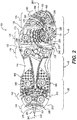
- FIG. 2 shows a bottom view of sole 105.
- forefoot region 16 may be subdivided into a first forefoot section 125, a second forefoot section 130, and a third forefoot section 135.
- first forefoot section 125, second forefoot section 130, and third forefoot section 135 may be separated by flex grooves.
- sole 105 may include a first flex groove 150, formed as an elongate recess in lower surface 110.
- First flex groove 150 may separate first forefoot section 125 from second forefoot section 130.
- first flex groove 150 may form a thinner portion (in a vertical direction) of an outsole portion of sole 105 than other portions of the outsole (such as first forefoot section 125 and second forefoot section 130), in order to provide increased flexibility of sole 105 in this area.
- first flex groove 150 may extend in a lateral direction.
- sole 105 may have a medial side 160 and a lateral side 165.
- first flex groove 150 may extend substantially from a medial edge 170 of lower surface 110 of sole 105 to a lateral edge 175 of outer surface 110.
- first flex groove 150 may extend completely from medial edge 170 to lateral edge 175, as shown in FIG. 2 .
- a second flex groove 155 may separate second forefoot section 130 from third forefoot section 135 and may be similarly configured to first flex groove 150.
- First forefoot section 125 may be disposed in a forward-most region of sole 105, and may include a first set of ground engaging members 180 extending substantially downward from lower surface 110 of sole 105.
- first set of ground engaging members 180 may form a substantially arcuate first arrangement.
- a first ground engaging member 185, a second ground engaging member 190, and a third ground engaging member 195 may be arranged in alignment with a first arc 200, as shown in FIG. 2 . That is, each ground engaging member of first set of ground engaging members 180 may have a length extending along first arc 200.
- First arc 200 may have a first concavity oriented in a generally lateral direction 205.
- the concavity of first arc 200 (generally lateral direction 205) may be oriented slightly rearward, as shown in FIG. 2 .
- This configuration may provide traction when a wearer is applying torque to the ground, for example, during a cricket swing, baseball swing, golf swing, or throwing of a baseball or football. During such movements, an athlete may turn their body, and thus, apply torque to the ground about the ball of the foot. Accordingly, providing arcuate ground engaging members oriented with a concavity in a generally lateral direction may prevent slippage in the lateral direction of the forward-most portion of the athlete's rear foot while performing such athletic movements.
- this arrangement may prevent or reduce undesired catching of the ground engaging members of the forward-most portion of the sole on the ground during running or other movements.
- second forefoot section 130 may be disposed rearward of first forefoot section 125, and may include a second set of ground engaging members 210 extending substantially downward from lower surface 110 of sole 105.
- Second set of ground engaging members 210 may form a substantially arcuate second arrangement.
- second set of ground engaging members 210 may be arranged along a second arc 215, as shown in FIG. 2 .
- second arc 215 may be substantially circular, and thus, may have a first radius 220 from a first center point 225.
- the substantially arcuate first arrangement is curved in a different direction than the second arrangement.
- the substantially arcuate first arrangement of first set of ground engaging members 180 (indicated by first arc 200) has a first concavity and the substantially arcuate second arrangement of second set of ground engaging members 210 has a second concavity oriented in an opposite direction and facing away from the first concavity.
- the first concavity may be oriented in generally lateral direction 205 and the second concavity may be oriented in a generally medial direction extending from second arc 215 toward center point 225.
- third forefoot section 130 may be disposed rearward of second forefoot section 130, and may include a third set of ground engaging members 230 extending substantially downward from lower surface 110 of sole 105.
- Third set of ground engaging members 230 may form a substantially arcuate third arrangement.
- third set of ground engaging members 210 may be arranged along a third arc 235, as shown in FIG. 2 .
- third arc 235 may be substantially circular, and thus, may have a second radius 240.
- the substantially arcuate third arrangement of third set of ground engaging members 230 may share an approximately similar center as the substantially arcuate second arrangement of second set of ground engaging members 210.
- third arc 235 may be located at second radius 240 from first center point 225.
- the use of stud-like ground engaging members about a center point in the second and third sections of the forefoot may provide traction in more of a variety of athletic movements.
- the stud-like ground engaging members may provide traction in all directions, and the arcuate arrangement about a center point in the ball of the foot may facilitate the application of torque and general traction when the athlete is on the ball of their foot.
- sole 105 may have a particular arrangement of ground engaging members in heel region 20.
- sole 105 may include a fourth set of ground engaging members 140 extending substantially downward from lower surface 110.
- Fourth set of ground engaging members 140 may form a substantially arcuate fourth arrangement, which may be curved along a fourth arc 245 about a second center point 250.
- Fourth arc 245 may have a third radius 255 from second center point 250, as shown in FIG. 2 .
- the substantially arcuate fourth arrangement may have a concavity in a rearward direction (from fourth arc 245 toward second center point 250). The rearward concavity may provide traction during both acceleration and deceleration.
- Sole 105 may also include a fifth set of ground engaging members 145 in heel region 20 of the article of footwear, extending substantially downward from lower surface 110.
- Fifth set of ground engaging members 145 may form a substantially arcuate fifth arrangement, which may be curved along a fifth arc 260 about second center point 250.
- Fifth arc 260 may have a fourth radius 265 from second center point 250, as shown in FIG. 2 .
- the substantially arcuate fifth arrangement may have a concavity in a rearward direction (from fifth arc 260 toward second center point 250).
- Fifth set of ground engaging members 145 may be radially spaced from fourth set of ground engaging members 140, and thus, may be closer to second center point 250 than fourth set of ground engaging members 140.
- fifth set of ground engaging members 145 being longitudinally displaced rearward of the fourth set of ground engaging members 140. That is, fourth radius 265 may be shorter than third radius 255.
- fifth set of ground engaging members 145 may be discontinuous with fourth set of ground engaging members 140.
- the term "discontinuous" shall refer to ground engaging members arranged in a first pattern in a first area and a second pattern in a second area, where spacing between the first area and the second area provides a discontinuity between the first pattern and the second pattern.
- the first pattern may include a plurality of ground engaging members arranged with a regular spacing.
- the second area may be located a distance from the first area that is greater than the regular spacing between ground engaging members of the first pattern.
- fourth set of ground engaging members 140 and/or fifth set of ground engaging members 145 may include two or more rows of ground engaging members that are radially spaced from one another, in a substantially concentric configuration.
- fifth set of ground engaging members 145 may be concentric with fourth set of ground engaging members 140.
- the center point about which the fourth set of ground engaging members 140 and fifth set of ground engaging members 145 are arced may be located off sole 105. That is, in some embodiments, second center point 250 of the substantially arcuate fourth arrangement and the substantially arcuate fifth arrangement may be located beyond a peripheral edge 270 of sole 105. For example, as shown in FIG. 2 , in some embodiments, second center point 250 may be located rearward of a rear-most edge 275 of sole 105. Further, in some embodiments, second center point 250 may be located in substantial alignment with a longitudinal central axis 280 of sole 105.
- Providing the elongate ground engaging members at the rearward-most portion of the sole may provide traction during deceleration.
- these rear-most ground engaging members with a concavity that is oriented rearward, more ground engaging members may be provided at the peripheral edge of the sole in this region, due to the forward facing concavity of the arc formed by the peripheral edge of the heel. That is, instead of having one long ground engaging member along the peripheral edge, the three ground engaging members terminate in six end portions proximate the peripheral edge.
- deceleration may be provided that is similar to concave forward designs, however, additional traction is also provided at the periphery in a wider range of athletic movements.
- sole 105 may also include a plurality of receptacles 285, which may be configured to receive threaded portions of removable ground engaging members (not shown). Further details of receptacles 285 and other features of sole 105 are disclosed in Binzer, U.S. Patent Application Publication No. _, published on _ (Now U.S. Patent Application Number _, filed on even date herewith [attorney docket no. 51-2878]), and entitled "Reinforcing Member for Article of Footwear," the entire disclosure of which is incorporated herein by reference.
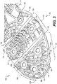
- FIG. 3 shows a perspective view of forefoot region 16 of sole 105.
- the ground engaging members of first set of ground engaging members 180 may have a substantially different shape than the ground engaging members of second set of ground engaging members 210.
- the ground engaging members of second set of ground engaging members 210 may have a stud-like, rectangular shape
- the ground engaging members of first set of ground engaging members 180 may have a substantially elongate shape.
- the ground engaging members in first set of ground engaging members 180 may be curved along first arc 200.
- the elongate shape of the ground engaging members in first forefoot section 125 is illustrated in FIG. 3 using a peripheral ground engaging member 290.
- First set of ground engaging members 180 may each have an elongate configuration similar to peripheral ground engaging member 290. As shown in FIG. 3 , peripheral ground engaging member 290 may have a width 295 that is shorter than a length 300. Width 295 may be substantially constant along length 300. In addition, peripheral ground engaging member 290 may have a height 305, which may be constant along length 300.
- first set of ground engaging members 180, second set of ground engaging members 210, and third set of ground engaging members 230 may include two or more rows of ground engaging members having substantially the same shape. That is, within a set of ground engaging members, the ground engaging members in each row of ground engaging members may have the same shape as the ground engaging members in adjacent rows. For example, as shown in FIG. 3 , first ground engaging member 185, second ground engaging member 190, and third ground engaging member may all have an elongate shape. Similarly, the ground engaging members of second set of ground engaging members 210 may be substantially square or rectangular in each row of the set.
- the shapes of these ground engaging members may be substantially different from set to set as with first set of ground engaging members 180 and second set of ground engaging members 210.
- the two or more rows of second set of ground engaging members may be radially spaced in a substantially concentric configuration.
- ground engaging members may differ slightly but still have substantially the same general shape.
- elongate ground engaging members such as provided in first forefoot section 125 may have various lengths.
- the ground engaging members of second forefoot section 130 may have varying dimensions, yet all have a substantially rectangular or trapezoidal shape.
- elongate ground engaging members may be continuous, like second ground engaging member 190 and third ground engaging member 195.
- elongate ground engaging members may be interrupted by other features of sole 105, such as first ground engaging member 185, which is separated into two portions.
- spacing between ground engaging members in the same set may vary. For example, rows that are more radially outward may or may not include larger spacing between ground engaging members than rows that are positioned more radially inward.
- FIG. 4 shows a perspective view of heel region 20 of sole 105.
- fourth set of ground engaging members 140 and/or second set of ground engaging members 145 may include two or more rows of ground engaging members having substantially the same shape. In some embodiments, these rows may be radially spaced in a substantially concentric configuration, as shown in FIG. 4 .
- fourth set of ground engaging members 140 may include a first row 310 and a second row 315.
- First row 310 may include an arrangement of substantially rectangular ground engaging members 312.
- second row 315 may also include a similar pattern of substantially rectangular ground engaging members.
- first row 310 may also include an arrangement of substantially circular ground engaging members 313.
- second row 315 may also include a similar pattern of substantially circular ground engaging members.
- fourth set of ground engaging members 140 may consist of the arrangement of substantially rectangular ground engaging members 312 and/or the substantially circular ground engaging members 313.
- fifth set of ground engaging members 145 may include a fourth row 320, a fifth row 325, and a sixth row 330. As shown in FIG. 4 , fourth row 320, fifth row 325, and sixth row 330 may each include an elongate ground engaging member. It will be noted that, in some embodiments, the ground engaging members in fifth set of ground engaging members 145 may have a substantially different shape than the ground engaging members of the fourth set of ground engaging members 140. Also, fifth set of ground engaging members 145 may be radially spaced from fourth set of ground engaging members 140, as indicated by a gap 335, which is significantly larger than the spacing between ground engaging members in either fourth set 140 or fifth set 145.
- the elongate ground engaging members of fifth set of ground engaging members 145 may have a substantially similar shape to the ground engaging members in first forefoot section 125, including first set of ground engaging members 180.
- the elongate members of fifth set 145 may have a substantially constant width and height.
- the invention also contains the following items:
Landscapes
- Chemical & Material Sciences (AREA)
- Engineering & Computer Science (AREA)
- Materials Engineering (AREA)
- Footwear And Its Accessory, Manufacturing Method And Apparatuses (AREA)
Abstract
Description
- This application claims priority under 35 U.S.C. § 119(e) to
U.S. Provisional Patent Application Number 61/704,440 U.S. Provisional Patent Application Number 61/704,444 - The present invention relates generally to a tread pattern for an article of footwear. It is advantageous, when participating in various activities, to have footwear that provides traction and stability on the surface upon which the activities take place. Accordingly, sole structures for articles of footwear have been developed with traction systems that include ground engaging members to provide traction on a variety of surfaces. Examples include cleated shoes developed for outdoor sports, such as soccer, football, and baseball.
- In one aspect, the present disclosure is directed to an article of footwear, including a sole having a lower surface exposed to the ground. The article of footwear may include a forefoot region having a first forefoot section and a second forefoot section separated by a first flex groove. The first flex groove may be formed by an upwardly extending elongate recess in the lower surface of the sole. In addition, the first forefoot section may include a first set of ground engaging members extending substantially downward from the lower surface of the sole, the first set of ground engaging members forming a substantially arcuate first arrangement. Also, the second forefoot section may include a second set of ground engaging members extending substantially downward from the lower surface of the sole, the second set of ground engaging members forming a substantially arcuate second arrangement. The first arrangement may be curved in a different direction than the second arrangement. In addition, each ground engaging member of the first set of ground engaging members may have a length extending along an arc.
- In another aspect, the present disclosure is directed to an article of footwear including a ground engaging sole. The ground engaging sole may include a lower surface exposed to the ground and divided, in a forefoot region of the article of footwear, into a first forefoot section and a second forefoot section by a first flex groove formed by an upwardly extending elongate recess in the lower surface of the sole. The first forefoot section may include a first set of ground engaging members extending substantially downward from the lower surface of the sole, the first set of ground engaging members forming a substantially arcuate first arrangement. The second forefoot section may include a second set of ground engaging members extending substantially downward from the lower surface of the sole, the second set of ground engaging members forming a substantially arcuate second arrangement curved in a different direction than the arcuate arrangement of the first set of ground engaging members. The first set of ground engaging members may include two or more rows of ground engaging members having substantially the same shape and the second set of ground engaging members includes two or more rows of ground engaging members having substantially the same shape. In addition, the first set of ground engaging members may each have a first shape and the second set of ground engaging members may each have a second shape substantially different from the first shape.
- In another aspect, the present disclosure is directed to an article of footwear including a sole. The sole may include a lower surface exposed to the ground. The lower surface may include a first forefoot section separated from a second forefoot section by a first flex groove formed by an upwardly extending elongate recess in the lower surface of the sole. In addition, the lower surface may include a third forefoot section separated from the second forefoot section by a second flex groove formed by an upwardly extending elongate recess in the lower surface of the sole. Also, the first forefoot section may include a first set of ground engaging members extending substantially downward from the lower surface of the sole, the first set of ground engaging members forming a substantially arcuate first arrangement having a first concavity oriented in a first lateral direction. Further, the second forefoot section may include a second set of ground engaging members extending substantially downward from the lower surface of the sole, the second set of ground engaging members forming a substantially arcuate second arrangement having a first concavity oriented in a second lateral direction substantially opposite the first lateral direction and away from the first set of ground engaging members. The third forefoot section may include a third set of ground engaging members extending substantially downward from the lower surface of the sole, the third set of ground engaging members forming a substantially arcuate third arrangement that shares an approximately similar center as the substantially arcuate second arrangement of the second set of ground engaging members.
- In another aspect, the present disclosure is directed to an article of footwear including a ground engaging sole. The sole may include a lower surface exposed to the ground. In addition, the sole may include a first set of ground engaging members extending substantially downward from the lower surface of the sole in a heel region of the article of footwear, the first set of ground engaging members forming a substantially arcuate first arrangement curved about a center point. The sole may further include a second set of ground engaging members in the heel region of the article of footwear and extending substantially downward from the lower surface of the sole, the second set of ground engaging members being radially spaced from the first set of ground engaging members. The second set of ground engaging members may be concentric with the first set of ground engaging members, forming a substantially arcuate second arrangement curved about approximately the same center point as the first set of ground engaging members.
- In another aspect, the present disclosure is directed to an article of footwear including a ground engaging sole. The sole may include a lower surface exposed to the ground. The sole may also include a first set of ground engaging members extending substantially downward from the lower surface of the sole in a heel region of the article of footwear, the first set of ground engaging members forming a substantially arcuate arrangement with a concavity in a rearward direction. In addition, the sole may include a second set of ground engaging members in the heel region of the article of footwear, extending substantially downward from the lower surface of the sole, and forming a substantially arcuate arrangement with a concavity in a rearward direction. The second set of ground engaging members may be longitudinally displaced rearward of, and discontinuous with, the first set of ground engaging members. In addition, the first set of ground engaging members may include two or more rows of ground engaging members having substantially the same shape and the second set of ground engaging members includes two or more rows of ground engaging members having substantially the same shape. Further, each ground engaging member in the second set of ground engaging members may have a length extending along an arc, a width that is shorter than the length and substantially constant along the length, and a height that is substantially constant along the length.
- The invention can be better understood with reference to the following drawings and description. The components in the figures are not necessarily to scale, emphasis instead being placed upon illustrating the principles of the invention. Moreover, in the figures, like reference numerals designate corresponding parts throughout the different views.
-
FIG. 1 shows an elevation side view of an exemplary article of footwear; -
FIG. 2 shows a bottom view of an exemplary sole for an article of footwear; -
FIG. 3 shows a perspective view of a forefoot region of the sole shown inFIG. 2 ; and -
FIG. 4 shows a perspective view of a heel region of the sole shown inFIG. 2 . - The following discussion and accompanying figures disclose a sole structure for an article of footwear. Concepts associated with the footwear disclosed herein may be applied to a variety of athletic footwear types, including cricket shoes, golf shoes, soccer shoes, baseball shoes, football shoes, and hiking shoes and boots, for example. Accordingly, the concepts disclosed herein apply to a wide variety of footwear types.
- For consistency and convenience, directional adjectives are employed throughout this detailed description corresponding to the illustrated embodiments. The term "longitudinal," as used throughout this detailed description and in the claims, refers to a direction extending a length of a sole structure, i.e., extending from a forefoot portion to a heel portion of the sole. The term "forward" is used to refer to the general direction in which the toes of a foot point, and the term "rearward" is used to refer to the opposite direction, i.e., the direction in which the heel of the foot is facing.
- The term "lateral direction," as used throughout this detailed description and in the claims, refers to a side-to-side direction extending a width of a sole. In other words, the lateral direction may extend between a medial side and a lateral side of an article of footwear, with the lateral side of the article of footwear being the surface that faces away from the other foot, and the medial side being the surface that faces toward the other foot.
- The term "lateral axis," as used throughout this detailed description and in the claims, refers to an axis oriented in a lateral direction.
- The term "horizontal," as used throughout this detailed description and in the claims, refers to any direction substantially parallel with the ground, including the longitudinal direction, the lateral direction, and all directions in between. Similarly, the term "side," as used in this specification and in the claims, refers to any portion of a component facing generally in a lateral, medial, forward, and/or rearward direction, as opposed to an upward or downward direction.
- The term "vertical," as used throughout this detailed description and in the claims, refers to a direction generally perpendicular to both the lateral and longitudinal directions. For example, in cases where a sole is planted flat on a ground surface, the vertical direction may extend from the ground surface upward. It will be understood that each of these directional adjectives may be applied to individual components of a sole. The term "upward" refers to the vertical direction heading away from a ground surface, while the term "downward" refers to the vertical direction heading towards the ground surface. Similarly, the terms "top," "upper," and other similar terms refer to the portion of an object substantially furthest from the ground in a vertical direction, and the terms "bottom," "lower," and other similar terms refer to the portion of an object substantially closest to the ground in a vertical direction.
- For purposes of this disclosure, the foregoing directional terms, when used in reference to an article of footwear, shall refer to the article of footwear when sitting in an upright position, with the sole facing groundward, that is, as it would be positioned when worn by a wearer standing on a substantially level surface.
- In addition, for purposes of this disclosure, the term "fixedly attached" shall refer to two components joined in a manner such that the components may not be readily separated (for example, without destroying one or both of the components). Exemplary modalities of fixed attachment may include joining with permanent adhesive, rivets, stitches, nails, staples, welding or other thermal bonding, and/or other joining techniques. In addition, two components may be "fixedly attached" by virtue of being integrally formed, for example, in a molding process.
-
FIG. 1 depicts an embodiment of an article offootwear 10, which may include a sole 105 and an upper 14. For reference purposes,footwear 10 may be divided into three general regions: aforefoot region 16, amidfoot region 18, and aheel region 20.Forefoot region 16 generally includes portions offootwear 10 corresponding with the toes and the joints connecting the metatarsals with the phalanges.Midfoot region 18 generally includes portions offootwear 10 corresponding with an arch area of the foot.Heel region 20 generally corresponds with rear portions of the foot, including the calcaneus bone.Regions footwear 10. Rather,regions footwear 10 to aid in the following discussion. - Since sole 105 and upper 14 both span substantially the entire length of
footwear 10, theterms forefoot region 16,midfoot region 18, andheel region 20 apply not only tofootwear 10 in general, but also to sole structure 12 and upper 14, as well as the individual elements of sole structure 12 and upper 14. - As shown in
FIG. 1 , sole 105 may have alower surface 110 exposed to the ground.Lower surface 110 may include various ground engaging members (cleats) extending generally downward fromlower surface 110. These ground engaging members may be disposed in arcuate arrangements to provide directionally specific traction. Exemplary such arcuate arrangements are discussed in greater detail below. -
FIG. 2 shows a bottom view of sole 105. As shown inFIG. 2 ,forefoot region 16 may be subdivided into afirst forefoot section 125, asecond forefoot section 130, and athird forefoot section 135. In some embodiments,first forefoot section 125,second forefoot section 130, andthird forefoot section 135 may be separated by flex grooves. For example, as shown inFIG. 2 , sole 105 may include afirst flex groove 150, formed as an elongate recess inlower surface 110.First flex groove 150 may separatefirst forefoot section 125 fromsecond forefoot section 130. In some embodiments,first flex groove 150 may form a thinner portion (in a vertical direction) of an outsole portion of sole 105 than other portions of the outsole (such asfirst forefoot section 125 and second forefoot section 130), in order to provide increased flexibility of sole 105 in this area. - In some embodiments,
first flex groove 150 may extend in a lateral direction. For example, sole 105 may have amedial side 160 and alateral side 165. As shown inFIG. 2 ,first flex groove 150 may extend substantially from amedial edge 170 oflower surface 110 of sole 105 to alateral edge 175 ofouter surface 110. Further, in some embodiments,first flex groove 150 may extend completely frommedial edge 170 tolateral edge 175, as shown inFIG. 2 . Asecond flex groove 155 may separatesecond forefoot section 130 fromthird forefoot section 135 and may be similarly configured tofirst flex groove 150. -
First forefoot section 125 may be disposed in a forward-most region of sole 105, and may include a first set ofground engaging members 180 extending substantially downward fromlower surface 110 of sole 105. In some embodiments first set ofground engaging members 180 may form a substantially arcuate first arrangement. For example, a firstground engaging member 185, a secondground engaging member 190, and a thirdground engaging member 195 may be arranged in alignment with afirst arc 200, as shown inFIG. 2 . That is, each ground engaging member of first set ofground engaging members 180 may have a length extending alongfirst arc 200. -
First arc 200 may have a first concavity oriented in a generallylateral direction 205. In some embodiments, the concavity of first arc 200 (generally lateral direction 205) may be oriented slightly rearward, as shown inFIG. 2 . This configuration may provide traction when a wearer is applying torque to the ground, for example, during a cricket swing, baseball swing, golf swing, or throwing of a baseball or football. During such movements, an athlete may turn their body, and thus, apply torque to the ground about the ball of the foot. Accordingly, providing arcuate ground engaging members oriented with a concavity in a generally lateral direction may prevent slippage in the lateral direction of the forward-most portion of the athlete's rear foot while performing such athletic movements. In addition, since many of these elongate ground engaging members in the forward-most portion of the sole are at least somewhat longitudinally aligned, this arrangement may prevent or reduce undesired catching of the ground engaging members of the forward-most portion of the sole on the ground during running or other movements. - As shown in
FIG. 2 ,second forefoot section 130 may be disposed rearward offirst forefoot section 125, and may include a second set ofground engaging members 210 extending substantially downward fromlower surface 110 of sole 105. Second set ofground engaging members 210 may form a substantially arcuate second arrangement. For example, second set ofground engaging members 210 may be arranged along asecond arc 215, as shown inFIG. 2 . In some embodiments,second arc 215 may be substantially circular, and thus, may have afirst radius 220 from afirst center point 225. - In some embodiments, the substantially arcuate first arrangement is curved in a different direction than the second arrangement. As shown in
FIG. 2 , the substantially arcuate first arrangement of first set of ground engaging members 180 (indicated by first arc 200) has a first concavity and the substantially arcuate second arrangement of second set ofground engaging members 210 has a second concavity oriented in an opposite direction and facing away from the first concavity. For example, as shown inFIG. 2 , the first concavity may be oriented in generallylateral direction 205 and the second concavity may be oriented in a generally medial direction extending fromsecond arc 215 towardcenter point 225. - As shown in
FIG. 2 ,third forefoot section 130 may be disposed rearward ofsecond forefoot section 130, and may include a third set ofground engaging members 230 extending substantially downward fromlower surface 110 of sole 105. Third set ofground engaging members 230 may form a substantially arcuate third arrangement. For example, third set ofground engaging members 210 may be arranged along athird arc 235, as shown inFIG. 2 . In some embodiments,third arc 235 may be substantially circular, and thus, may have asecond radius 240. In some embodiments, the substantially arcuate third arrangement of third set ofground engaging members 230 may share an approximately similar center as the substantially arcuate second arrangement of second set ofground engaging members 210. Thus,third arc 235 may be located atsecond radius 240 fromfirst center point 225. - The use of stud-like ground engaging members about a center point in the second and third sections of the forefoot may provide traction in more of a variety of athletic movements. The stud-like ground engaging members may provide traction in all directions, and the arcuate arrangement about a center point in the ball of the foot may facilitate the application of torque and general traction when the athlete is on the ball of their foot.
- In some embodiments, sole 105 may have a particular arrangement of ground engaging members in
heel region 20. For example, in some embodiments, sole 105 may include a fourth set ofground engaging members 140 extending substantially downward fromlower surface 110. Fourth set ofground engaging members 140 may form a substantially arcuate fourth arrangement, which may be curved along afourth arc 245 about asecond center point 250.Fourth arc 245 may have athird radius 255 fromsecond center point 250, as shown inFIG. 2 . As also shown inFIG. 2 , in some embodiments, the substantially arcuate fourth arrangement may have a concavity in a rearward direction (fromfourth arc 245 toward second center point 250). The rearward concavity may provide traction during both acceleration and deceleration. -
Sole 105 may also include a fifth set ofground engaging members 145 inheel region 20 of the article of footwear, extending substantially downward fromlower surface 110. Fifth set ofground engaging members 145 may form a substantially arcuate fifth arrangement, which may be curved along afifth arc 260 aboutsecond center point 250.Fifth arc 260 may have afourth radius 265 fromsecond center point 250, as shown inFIG. 2 . As also shown inFIG. 2 , in some embodiments, the substantially arcuate fifth arrangement may have a concavity in a rearward direction (fromfifth arc 260 toward second center point 250). - Fifth set of
ground engaging members 145 may be radially spaced from fourth set ofground engaging members 140, and thus, may be closer tosecond center point 250 than fourth set ofground engaging members 140. For example, fifth set ofground engaging members 145 being longitudinally displaced rearward of the fourth set ofground engaging members 140. That is,fourth radius 265 may be shorter thanthird radius 255. In addition, fifth set ofground engaging members 145 may be discontinuous with fourth set ofground engaging members 140. As used in the present disclosure, the term "discontinuous" shall refer to ground engaging members arranged in a first pattern in a first area and a second pattern in a second area, where spacing between the first area and the second area provides a discontinuity between the first pattern and the second pattern. For example, the first pattern may include a plurality of ground engaging members arranged with a regular spacing. The second area may be located a distance from the first area that is greater than the regular spacing between ground engaging members of the first pattern. - In some embodiments, fourth set of
ground engaging members 140 and/or fifth set ofground engaging members 145 may include two or more rows of ground engaging members that are radially spaced from one another, in a substantially concentric configuration. In addition, in some embodiments, fifth set ofground engaging members 145 may be concentric with fourth set ofground engaging members 140. - In some embodiments, the center point about which the fourth set of
ground engaging members 140 and fifth set ofground engaging members 145 are arced may be located off sole 105. That is, in some embodiments,second center point 250 of the substantially arcuate fourth arrangement and the substantially arcuate fifth arrangement may be located beyond aperipheral edge 270 of sole 105. For example, as shown inFIG. 2 , in some embodiments,second center point 250 may be located rearward of arear-most edge 275 of sole 105. Further, in some embodiments,second center point 250 may be located in substantial alignment with a longitudinalcentral axis 280 of sole 105. - Providing the elongate ground engaging members at the rearward-most portion of the sole may provide traction during deceleration. In addition, by making these rear-most ground engaging members with a concavity that is oriented rearward, more ground engaging members may be provided at the peripheral edge of the sole in this region, due to the forward facing concavity of the arc formed by the peripheral edge of the heel. That is, instead of having one long ground engaging member along the peripheral edge, the three ground engaging members terminate in six end portions proximate the peripheral edge. Thus, deceleration may be provided that is similar to concave forward designs, however, additional traction is also provided at the periphery in a wider range of athletic movements.
- In some embodiments, sole 105 may also include a plurality of
receptacles 285, which may be configured to receive threaded portions of removable ground engaging members (not shown). Further details ofreceptacles 285 and other features of sole 105 are disclosed in Binzer, U.S. Patent Application Publication No. _, published on _ (Now U.S. Patent Application Number _, filed on even date herewith [attorney docket no. 51-2878]), and entitled "Reinforcing Member for Article of Footwear," the entire disclosure of which is incorporated herein by reference. -
FIG. 3 shows a perspective view offorefoot region 16 of sole 105. As shown inFIG. 3 , the ground engaging members of first set ofground engaging members 180 may have a substantially different shape than the ground engaging members of second set ofground engaging members 210. For example, the ground engaging members of second set ofground engaging members 210 may have a stud-like, rectangular shape, the ground engaging members of first set ofground engaging members 180 may have a substantially elongate shape. In some embodiments, the ground engaging members in first set ofground engaging members 180 may be curved alongfirst arc 200. The elongate shape of the ground engaging members in first forefoot section 125 (including first set of ground engaging members 180) is illustrated inFIG. 3 using a peripheralground engaging member 290. First set ofground engaging members 180 may each have an elongate configuration similar to peripheralground engaging member 290. As shown inFIG. 3 , peripheralground engaging member 290 may have awidth 295 that is shorter than alength 300.Width 295 may be substantially constant alonglength 300. In addition, peripheralground engaging member 290 may have aheight 305, which may be constant alonglength 300. - In some embodiments, at least one of first set of
ground engaging members 180, second set ofground engaging members 210, and third set ofground engaging members 230 may include two or more rows of ground engaging members having substantially the same shape. That is, within a set of ground engaging members, the ground engaging members in each row of ground engaging members may have the same shape as the ground engaging members in adjacent rows. For example, as shown inFIG. 3 , firstground engaging member 185, secondground engaging member 190, and third ground engaging member may all have an elongate shape. Similarly, the ground engaging members of second set ofground engaging members 210 may be substantially square or rectangular in each row of the set. It will also be noted that, in some embodiments, the shapes of these ground engaging members may be substantially different from set to set as with first set ofground engaging members 180 and second set ofground engaging members 210. As further illustrated inFIG. 3 , the two or more rows of second set of ground engaging members may be radially spaced in a substantially concentric configuration. - It will also be noted that, in some embodiments, ground engaging members may differ slightly but still have substantially the same general shape. For example, elongate ground engaging members, such as provided in
first forefoot section 125 may have various lengths. Similarly, as shown inFIG. 3 , the ground engaging members ofsecond forefoot section 130 may have varying dimensions, yet all have a substantially rectangular or trapezoidal shape. In addition, in some embodiments, elongate ground engaging members may be continuous, like secondground engaging member 190 and thirdground engaging member 195. In some embodiments, elongate ground engaging members may be interrupted by other features of sole 105, such as firstground engaging member 185, which is separated into two portions. In some embodiments, spacing between ground engaging members in the same set may vary. For example, rows that are more radially outward may or may not include larger spacing between ground engaging members than rows that are positioned more radially inward. -
FIG. 4 shows a perspective view ofheel region 20 of sole 105. In some embodiments, fourth set ofground engaging members 140 and/or second set ofground engaging members 145 may include two or more rows of ground engaging members having substantially the same shape. In some embodiments, these rows may be radially spaced in a substantially concentric configuration, as shown inFIG. 4 . For example, fourth set ofground engaging members 140 may include afirst row 310 and asecond row 315.First row 310 may include an arrangement of substantially rectangularground engaging members 312. As shown inFIG. 4 ,second row 315 may also include a similar pattern of substantially rectangular ground engaging members. In addition,first row 310 may also include an arrangement of substantially circularground engaging members 313. As shown inFIG. 4 ,second row 315 may also include a similar pattern of substantially circular ground engaging members. In some embodiments, fourth set ofground engaging members 140 may consist of the arrangement of substantially rectangularground engaging members 312 and/or the substantially circularground engaging members 313. - In addition, fifth set of
ground engaging members 145 may include afourth row 320, afifth row 325, and asixth row 330. As shown inFIG. 4 ,fourth row 320,fifth row 325, andsixth row 330 may each include an elongate ground engaging member. It will be noted that, in some embodiments, the ground engaging members in fifth set ofground engaging members 145 may have a substantially different shape than the ground engaging members of the fourth set ofground engaging members 140. Also, fifth set ofground engaging members 145 may be radially spaced from fourth set ofground engaging members 140, as indicated by agap 335, which is significantly larger than the spacing between ground engaging members in eitherfourth set 140 orfifth set 145. - It will also be noted that the elongate ground engaging members of fifth set of
ground engaging members 145 may have a substantially similar shape to the ground engaging members infirst forefoot section 125, including first set ofground engaging members 180. For example, the elongate members offifth set 145 may have a substantially constant width and height. - While various embodiments of the invention have been described, the description is intended to be exemplary, rather than limiting and it will be apparent to those of ordinary skill in the art that many more embodiments and implementations are possible that are within the scope of the invention. Although many possible combinations of features are shown in the accompanying figures and discussed in this detailed description, many other combinations of the disclosed features are possible. Therefore, it will be understood that any of the features shown and/or discussed in the present disclosure may be implemented together in any suitable combination and that features of one embodiment may be implemented in other disclosed embodiments. Accordingly, the invention is not to be restricted except in light of the attached claims and their equivalents. Also, various modifications and changes may be made within the scope of the attached claims.
- The invention also contains the following items:
- Item 1. An article of footwear, comprising:
- a sole having a lower surface exposed to the ground;
- a forefoot region of the article of footwear having a first forefoot section and a second forefoot section separated by a first flex groove;
- the first flex groove formed by an upwardly extending elongate recess in the lower surface of the sole;
- the first forefoot section including a first set of ground engaging members extending substantially downward from the lower surface of the sole, the first set of ground engaging members forming a substantially arcuate first arrangement; and
- the second forefoot section including a second set of ground engaging members extending substantially downward from the lower surface of the sole, the second set of ground engaging members forming a substantially arcuate second arrangement;
- wherein the first arrangement is curved in a different direction than the second arrangement; and
- wherein each ground engaging member of the first set of ground engaging members has a length extending along an arc.
- Item 2. The article of footwear of item 1, wherein the ground engaging members in the first set of ground engaging members has a width shorter than the length and substantially constant along the length.
- Item 3. The article of footwear of item 1, wherein each of the ground engaging members in the first set of ground engaging members has a substantially constant height.
- Item 4. The article of footwear of item 1, wherein the substantially arcuate first arrangement of the first set of ground engaging members has a first concavity and the substantially arcuate second arrangement of the second set of ground engaging members has a second concavity oriented in an opposite direction and facing away from the first concavity.
- Item 5. The article of footwear of item 4, wherein the first concavity is oriented in a first generally lateral direction and the second concavity is oriented in a second generally medial direction.
- Item 6. The article of footwear of item 5, wherein the first forefoot section is disposed in a forward-most region of the sole, and the second forefoot section is disposed rearward of the first forefoot section.
- Item 7. The article of footwear of item 1, wherein the second set of ground engaging members includes two or more rows of ground engaging members having substantially the same shape.
- Item 8. The article of footwear of item 1, wherein the ground engaging members of the first set of ground engaging members have a substantially different shape than the ground engaging members of the second set of ground engaging members.
- Item 9. The article of footwear of item 1, further including a third forefoot section including a third set of ground engaging members extending substantially downward from the lower surface of the sole, the third set of ground engaging members forming a substantially arcuate third arrangement that shares an approximately similar center as the substantially arcuate second arrangement of the second set of ground engaging members.
-
Item 10. An article of footwear including a ground engaging sole, comprising:- a lower surface exposed to the ground and divided, in a forefoot region of the article of footwear, into a first forefoot section and a second forefoot section by a first flex groove formed by an upwardly extending elongate recess in the lower surface of the sole;
- the first forefoot section including a first set of ground engaging members extending substantially downward from the lower surface of the sole, the first set of ground engaging members forming a substantially arcuate first arrangement; and
- the second forefoot section including a second set of ground engaging members extending substantially downward from the lower surface of the sole, the second set of ground engaging members forming a substantially arcuate second arrangement curved in a different direction than the arcuate arrangement of the first set of ground engaging members;
- wherein the first set of ground engaging members includes two or more rows of ground engaging members having substantially the same shape and the second set of ground engaging members includes two or more rows of ground engaging members having substantially the same shape; and
- wherein the first set of ground engaging members each have a first shape and the second set of ground engaging members each have a second shape substantially different from the first shape.
- Item 11. The article of footwear of
item 10, wherein the substantially arcuate first arrangement of the first set of ground engaging members has a first concavity and the substantially arcuate second arrangement of the second set of ground engaging members has a second concavity oriented in an opposite direction and facing away from the first concavity. - Item 12. The article of footwear of item 11, wherein the first concavity is oriented in a first generally lateral direction and the second concavity is oriented in a second generally medial direction.
- Item 13. The article of footwear of item 12, wherein the first forefoot section is disposed in a forward-most region of the sole, and the second forefoot section is disposed rearward of the first forefoot section.
-
Item 14. The article of footwear ofitem 10, further including a third forefoot section including a third set of ground engaging members extending substantially downward from the lower surface of the sole, the third set of ground engaging members forming a substantially arcuate third arrangement that shares an approximately similar center as the substantially arcuate second arrangement of the second set of ground engaging members. - Item 15. An article of footwear including a sole, comprising:
- a lower surface exposed to the ground;
- the lower surface including a first forefoot section separated from a second forefoot section by a first flex groove formed by an upwardly extending elongate recess in the lower surface of the sole;
- the lower surface further including a third forefoot section separated from the second forefoot section by a second flex groove formed by an upwardly extending elongate recess in the lower surface of the sole;
- the first forefoot section including a first set of ground engaging members extending substantially downward from the lower surface of the sole, the first set of ground engaging members forming a substantially arcuate first arrangement having a first concavity oriented in a first lateral direction; and
- the second forefoot section including a second set of ground engaging members extending substantially downward from the lower surface of the sole, the second set of ground engaging members forming a substantially arcuate second arrangement having a first concavity oriented in a second lateral direction substantially opposite the first lateral direction and away from the first set of ground engaging members;
- the third forefoot section including a third set of ground engaging members extending substantially downward from the lower surface of the sole, the third set of ground engaging members forming a substantially arcuate third arrangement that shares an approximately similar center as the substantially arcuate second arrangement of the second set of ground engaging members.
-
Item 16. The article of footwear of item 15, wherein the first concavity is oriented in a first generally lateral direction and the second concavity is oriented in a second generally medial direction. - Item 17. The article of footwear of
item 16, wherein the first forefoot section is disposed in a forward-most region of the sole, and the second forefoot section is disposed rearward of the first forefoot section. -
Item 18. The article of footwear of item 15, wherein at least one of the first set of ground engaging members, the second set of ground engaging members, and the third set of ground engaging members includes two or more rows of ground engaging members having substantially the same shape. - Item 19. The article of footwear of
item 18, wherein the two or more rows are radially spaced in a substantially concentric configuration. -
Item 20. The article of footwear of item 15, wherein the first forefoot section is separated from the first forefoot section by a first flex groove formed by an elongate recess extending upward into the sole, and wherein the second forefoot section is separated from the third forefoot section by a second flex groove formed by an elongate recess extending upward into the sole. - Item 21. An article of footwear including a ground engaging sole, comprising:
- a lower surface exposed to the ground;
- a first set of ground engaging members extending substantially downward from the lower surface of the sole in a heel region of the article of footwear, the first set of ground engaging members forming a substantially arcuate first arrangement curved about a center point; and
- a second set of ground engaging members in the heel region of the article of footwear and extending substantially downward from the lower surface of the sole, the second set of ground engaging members being radially spaced from the first set of ground engaging members;
- the second set of ground engaging members being concentric with the first set of ground engaging members, forming a substantially arcuate second arrangement curved about approximately the same center point as the first set of ground engaging members.
- Item 22. The article of footwear of item 21, wherein at least one of the first set of ground engaging members and the second set of ground engaging members includes two or more rows of ground engaging members having substantially the same shape.
- Item 23. The article of footwear of item 22, wherein the two or more rows are radially spaced in a substantially concentric configuration.
- Item 24. The article of footwear of item 21, wherein the center point of the substantially arcuate first arrangement and the substantially arcuate second arrangement is located beyond a peripheral edge of the sole.
- Item 25. The article of footwear of item 24, wherein the center point of the substantially arcuate first arrangement and the substantially arcuate second arrangement is located rearward of a rear-most edge of the sole, in substantial alignment with a longitudinal central axis of the sole.
- Item 26. The article of footwear of item 21, wherein the ground engaging members of the first set of ground engaging members have a substantially different shape than the ground engaging members of the second set of ground engaging members.
- Item 27. The article of footwear of item 21, wherein the ground engaging members of the second set of ground engaging members are located proximate a rear-most edge of the sole, and wherein the ground engaging members of the second set of ground engaging members each have an elongate shape, including a length extending along an arc of the substantially arcuate second arrangement.
- Item 28. The article of item 27, wherein the ground engaging members in the second set of ground engaging members has a width shorter than the length and substantially constant along the length, and a height that is substantially constant along the length.
- Item 29. An article of footwear including a ground engaging sole, comprising:
- a lower surface exposed to the ground;
- a first set of ground engaging members extending substantially downward from the lower surface of the sole in a heel region of the article of footwear, the first set of ground engaging members forming a substantially arcuate arrangement with a concavity in a rearward direction; and
- a second set of ground engaging members in the heel region of the article of footwear, extending substantially downward from the lower surface of the sole, and forming a substantially arcuate arrangement with a concavity in a rearward direction;
- the second set of ground engaging members being longitudinally displaced rearward of, and discontinuous with, the first set of ground engaging members;
- wherein the first set of ground engaging members includes two or more rows of ground engaging members having substantially the same shape and the second set of ground engaging members includes two or more rows of ground engaging members having substantially the same shape; and
- wherein each ground engaging member in the second set of ground engaging members has a length extending along an arc, a width that is shorter than the length and substantially constant along the length, and a height that is substantially constant along the length.
- Item 30. The article of footwear of item 29, wherein the ground engaging members of the first set of ground engaging members have a substantially different shape than the ground engaging members of the second set of ground engaging members.
- Item 31. The article of footwear of item 29, wherein the ground engaging members of the second set of ground engaging members are located proximate a rear-most edge of the sole.
- Item 32. The article of footwear of item 29, wherein the substantially arcuate first arrangement and the substantially arcuate second arrangement share a center point that is located beyond a peripheral edge of the sole.
- Item 33. The article of footwear of item 32, wherein the center point is located rearward of a rear-most edge of the sole, in substantial alignment with a longitudinal central axis of the sole.
- Item 34. An article of footwear including a ground engaging sole, comprising:
- a lower surface exposed to the ground;
- a first set of ground engaging members extending substantially downward from the lower surface of the sole in a heel region of the article of footwear, the first set of ground engaging members forming a substantially arcuate first arrangement with a concavity in a rearward direction; and
- a second set of ground engaging members in the heel region of the article of footwear, extending substantially downward from the lower surface of the sole, and forming a substantially arcuate second arrangement with a concavity in a rearward direction;
- the second set of ground engaging members being longitudinally displaced rearward of, and discontinuous with, the first set of ground engaging members;
- wherein the second set of ground engaging members are disposed proximate the rearward most edge of the lower surface of the sole; and
- wherein each ground engaging member in the second set of ground engaging members has a length extending along an arc.
- Item 35. The article of footwear of item 34, wherein the substantially arcuate first arrangement and the substantially arcuate second arrangement share a center point that is located beyond a peripheral edge of the sole.
- Item 36. The article of footwear of item 35, wherein the center point is located rearward of a rear-most edge of the sole, in substantial alignment with a longitudinal central axis of the sole.
- Item 37. The article of footwear of item 34, wherein the ground engaging members of the first set of ground engaging members have a substantially different shape than the ground engaging members of the second set of ground engaging members.
- Item 38. The article of footwear of item 34, wherein the ground engaging members of the second set of ground engaging members each have a width that is shorter than the length and substantially constant along the length, and a height that is substantially constant along the length.
- Item 39. The article of footwear of item 34, wherein at least one of the first set of ground engaging members and the second set of ground engaging members includes two or more rows of ground engaging members having substantially the same shape.
- Item 40. The article of footwear of item 39, wherein the two or more rows are radially spaced in a substantially concentric configuration.
Claims (15)
- An article of footwear including a ground engaging sole (105), comprising:a lower surface (110) exposed to the ground;a first set of ground engaging members (140) extending substantially downward from the lower surface (110) of the sole (105) in a heel region (20) of the article of footwear, the first set of ground engaging members (140) forming a substantially arcuate first arrangement curved about a center point (250); anda second set of ground engaging members (145) in the heel region (20) of the article of footwear and extending substantially downward from the lower surface (110) of the sole (105), the second set of ground engaging members (145) being radially spaced from the first set of ground engaging members (140);the second set of ground engaging members (145) being concentric with the first set of ground engaging members (140), forming a substantially arcuate second arrangement curved about approximately the same center point (250) as the first set of ground engaging members (140).
- The article of footwear of claim 1, wherein at least one of the first set of ground engaging members (140) and the second set of ground engaging members (145) includes two or more rows (310, 315, 320, 325, 330) of ground engaging members having substantially the same shape.
- The article of footwear of claim 2, wherein the two or more rows (310, 315, 320, 325, 330) are radially spaced in a substantially concentric configuration.
- The article of footwear of claim 1, wherein the center point (250) of the substantially arcuate first arrangement and the substantially arcuate second arrangement is located beyond a peripheral edge (270) of the sole (105).
- The article of footwear of claim 4, wherein the center point (250) of the substantially arcuate first arrangement and the substantially arcuate second arrangement is located rearward of a rear-most edge (275) of the sole (105), in substantial alignment with a longitudinal central axis of the sole (105).
- The article of footwear of claim 1, wherein the ground engaging members of the second set of ground engaging members (145) are located proximate a rear-most edge (275) of the sole (105), and wherein the ground engaging members of the second set of ground engaging members (145) each have an elongate shape, including a length extending along an arc (260) of the substantially arcuate second arrangement.
- The article of footwear of claim 6, wherein the ground engaging members in the second set of ground engaging members (145) has a width shorter than the length and substantially constant along the length, and a height that is substantially constant along the length.
- The article of footwear of claim 1, wherein:the first set of ground engaging members (140) is configured to form the substantially arcuate first arrangement with a concavity in a rearward direction;the second set of ground engaging members (145) is configured to form the substantially arcuate second arrangement with a concavity in a rearward direction;the second set of ground engaging members (145) being longitudinally displaced rearward of, and discontinuous with, the first set of ground engaging members (140);the first set of ground engaging members (140) includes two or more rows (310, 315) of ground engaging members having substantially the same shape and the second set of ground engaging members (145) includes two or more rows (320, 325, 330) of ground engaging members having substantially the same shape;andeach ground engaging member in the second set of ground engaging members (145) has a length extending along an arc, a width that is shorter than the length and substantially constant along the length, and a height that is substantially constant along the length.
- The article of footwear of claim 8, wherein the ground engaging members of the second set of ground engaging members (145) are located proximate a rear-most edge (275) of the sole (105).
- The article of footwear of claim 1, wherein:the first set of ground engaging members (140) is configured to form the substantially arcuate first arrangement with a concavity in a rearward direction;the second set of ground engaging members (145) is configured to form the substantially arcuate second arrangement with a concavity in a rearward direction;the second set of ground engaging members (145) is longitudinally displaced rearward of, and discontinuous with, the first set of ground engaging members (140);the second set of ground engaging members (145) are disposed proximate the rearward most edge (275) of the lower surface (110) of the sole (105); andeach ground engaging member in the second set of ground engaging members (145) has a length extending along an arc.
- The article of footwear of claim 8 or 10, wherein the substantially arcuate first arrangement and the substantially arcuate second arrangement share a center point (250) that is located beyond a peripheral edge (270) of the sole (105).
- The article of footwear of claim 11, wherein the center point (250) is located rearward of a rear-most edge (275) of the sole (105), in substantial alignment with a longitudinal central axis of the sole (105).
- The article of footwear of claim 1, 8 or 10, wherein the ground engaging members of the first set of ground engaging members (140) have a substantially different shape than the ground engaging members of the second set of ground engaging members (145).
- The article of footwear of claim 10, wherein the ground engaging members of the second set of ground engaging members (145) each have a width that is shorter than the length and substantially constant along the length, and a height that is substantially constant along the length.
- The article of footwear of claim 10, wherein at least one of the first set of ground engaging members (140) and the second set of ground engaging members (145) includes two or more rows (310, 315, 320, 325, 330) of ground engaging members having substantially the same shape,
particularly, wherein the two or more rows (310, 315, 320, 325, 330) are radially spaced in a substantially concentric configuration.
Applications Claiming Priority (6)
| Application Number | Priority Date | Filing Date | Title |
|---|---|---|---|
| US201261704444P | 2012-09-21 | 2012-09-21 | |
| US201261704440P | 2012-09-21 | 2012-09-21 | |
| US14/031,552 US20140082968A1 (en) | 2012-09-21 | 2013-09-19 | Tread Pattern For Article of Footwear |
| US14/031,510 US9427044B2 (en) | 2012-09-21 | 2013-09-19 | Reinforcing member for article of footwear |
| EP13788802.0A EP2866603B1 (en) | 2012-09-21 | 2013-09-20 | Tread pattern for article of footwear |
| PCT/US2013/060866 WO2014047419A1 (en) | 2012-09-21 | 2013-09-20 | Tread pattern for article of footwear |
Related Parent Applications (1)
| Application Number | Title | Priority Date | Filing Date |
|---|---|---|---|
| EP13788802.0A Division EP2866603B1 (en) | 2012-09-21 | 2013-09-20 | Tread pattern for article of footwear |
Publications (2)
| Publication Number | Publication Date |
|---|---|
| EP3446587A1 true EP3446587A1 (en) | 2019-02-27 |
| EP3446587B1 EP3446587B1 (en) | 2020-06-10 |
Family
ID=50337460
Family Applications (4)
| Application Number | Title | Priority Date | Filing Date |
|---|---|---|---|
| EP13788802.0A Active EP2866603B1 (en) | 2012-09-21 | 2013-09-20 | Tread pattern for article of footwear |
| EP17001853.5A Active EP3305118B1 (en) | 2012-09-21 | 2013-09-20 | Reinforcing member for article of footwear |
| EP18200599.1A Active EP3446587B1 (en) | 2012-09-21 | 2013-09-20 | Tread pattern for article of footwear |
| EP13788801.2A Active EP2869722B1 (en) | 2012-09-21 | 2013-09-20 | Article of footwear with reinforcing member |
Family Applications Before (2)
| Application Number | Title | Priority Date | Filing Date |
|---|---|---|---|
| EP13788802.0A Active EP2866603B1 (en) | 2012-09-21 | 2013-09-20 | Tread pattern for article of footwear |
| EP17001853.5A Active EP3305118B1 (en) | 2012-09-21 | 2013-09-20 | Reinforcing member for article of footwear |
Family Applications After (1)
| Application Number | Title | Priority Date | Filing Date |
|---|---|---|---|
| EP13788801.2A Active EP2869722B1 (en) | 2012-09-21 | 2013-09-20 | Article of footwear with reinforcing member |
Country Status (4)
| Country | Link |
|---|---|
| US (3) | US20140082968A1 (en) |
| EP (4) | EP2866603B1 (en) |
| AU (3) | AU2013317879B2 (en) |
| WO (2) | WO2014047404A1 (en) |
Families Citing this family (29)
| Publication number | Priority date | Publication date | Assignee | Title |
|---|---|---|---|---|
| US9055784B2 (en) * | 2011-01-06 | 2015-06-16 | Nike, Inc. | Article of footwear having a sole structure incorporating a plate and chamber |
| US9173450B2 (en) | 2011-09-16 | 2015-11-03 | Nike, Inc. | Medial rotational traction element arrangement for an article of footwear |
| US20140082968A1 (en) | 2012-09-21 | 2014-03-27 | Nike, Inc. | Tread Pattern For Article of Footwear |
| US9930934B2 (en) * | 2014-07-03 | 2018-04-03 | Nike, Inc. | Article of footwear with a segmented plate |
| USD763560S1 (en) * | 2014-08-05 | 2016-08-16 | Chinook Asia Llc | Boot outsole |
| TWI678167B (en) * | 2015-01-09 | 2019-12-01 | 巨大機械工業股份有限公司 | Soles of bicycle shoes |
| US9820529B2 (en) * | 2015-02-20 | 2017-11-21 | Nike, Inc. | Asymmetric torsion plate and composite sole structure for article of footwear |
| USD781040S1 (en) | 2015-07-24 | 2017-03-14 | Chinook Asia Llc | Sole for footwear |
| USD792068S1 (en) | 2015-08-07 | 2017-07-18 | Chinook Asia Llc | Shoe outsole |
| USD804793S1 (en) | 2015-08-28 | 2017-12-12 | Chinook Asia Llc | Boot outsole |
| USD789048S1 (en) | 2015-09-11 | 2017-06-13 | Chinook Asia Llc | Boot |
| USD794296S1 (en) | 2015-09-16 | 2017-08-15 | Chinook Asia Llc | Shoe outsole |
| USD776407S1 (en) | 2015-11-04 | 2017-01-17 | Adidas Ag | Shoe |
| US9591891B1 (en) * | 2015-12-07 | 2017-03-14 | Nike, Inc. | Article having sole assembly with cleats |
| USD807622S1 (en) * | 2016-06-03 | 2018-01-16 | Ecco Sko A/S | Sole for footwear |
| USD808136S1 (en) | 2016-06-03 | 2018-01-23 | Ecco Sko A/S | Sole for footwear |
| US10188319B2 (en) * | 2017-02-14 | 2019-01-29 | Aetrex Worldwide, Inc. | Method of producing a foot orthotic through 3D printing using foot pressure measurements and material hardness and/or structure to unload foot pressure |
| USD819311S1 (en) * | 2017-10-25 | 2018-06-05 | Nike, Inc. | Shoe midsole |
| USD871038S1 (en) * | 2017-11-17 | 2019-12-31 | Under Armour, Inc. | Sole structure |
| USD898612S1 (en) * | 2018-09-21 | 2020-10-13 | Roger Vivier S.P.A. | Buckle |
| CN109805512B (en) * | 2019-01-30 | 2021-03-12 | 泉州匹克鞋业有限公司 | Anti-cracking structure for flexion part of sports shoe |
| JP1652754S (en) | 2019-06-12 | 2020-02-10 | ||
| US11633010B2 (en) | 2020-07-22 | 2023-04-25 | Nike, Inc. | Sole structure for article of footwear and article of footwear |
| US11957216B2 (en) | 2020-09-11 | 2024-04-16 | Nike, Inc. | Sole structure for article of footwear |
| KR102427105B1 (en) * | 2021-03-25 | 2022-07-29 | (주)바라크 | Spikeless golf shoes |
| US20230137398A1 (en) * | 2021-10-28 | 2023-05-04 | Nike, Inc. | Sole structure for article of footwear |
| US12114735B2 (en) * | 2021-12-16 | 2024-10-15 | Jeffery Stuart Goff | Multiple cleat plate sole |
| US20230284732A1 (en) * | 2022-03-14 | 2023-09-14 | Hbn Shoe, Llc | Cleated footwear |
| WO2025144856A1 (en) * | 2023-12-30 | 2025-07-03 | Nike Innovate C.V. | Sole structure for an article of footwear |
Citations (5)
| Publication number | Priority date | Publication date | Assignee | Title |
|---|---|---|---|---|
| US485459A (en) * | 1892-11-01 | crocker | ||
| US4670997A (en) * | 1984-03-23 | 1987-06-09 | Stanley Beekman | Athletic shoe sole |
| US6101746A (en) * | 1996-08-23 | 2000-08-15 | Evans; Anthony | Footwear |
| US20020040539A1 (en) * | 2000-08-03 | 2002-04-11 | Kazuhiko Kobayashi | Golf shoes |
| US20080222921A1 (en) * | 2007-03-12 | 2008-09-18 | Nike, Inc. | Article of Footwear with Circular Tread Pattern |
Family Cites Families (100)
| Publication number | Priority date | Publication date | Assignee | Title |
|---|---|---|---|---|
| US362923A (en) | 1887-05-17 | Shank-stiffener | ||
| GB191105477A (en) | 1911-03-04 | 1911-04-27 | Walter Henry Huckett | Improved Detachable Studded Boot Sole for use in Cricket, Football and like Sports. |
| US1560995A (en) * | 1924-06-11 | 1925-11-10 | Kaplan Louis | Sole |
| US1528782A (en) * | 1924-11-04 | 1925-03-10 | Eric S Perry | Athletic shoe sole |
| US1706478A (en) | 1924-12-03 | 1929-03-26 | United Shoe Machinery Corp | Resilient shank stiffener |
| US1594965A (en) * | 1925-03-02 | 1926-08-03 | Kaplan Louis | Heel |
| GB379872A (en) | 1931-09-21 | 1932-09-08 | Edgar Freemantle Towell | Improvements in cricket boots |
| CH246465A (en) | 1945-10-02 | 1947-01-15 | Soc D Rech Et D Applic Tech | Shoe. |
| GB1174099A (en) | 1966-12-02 | 1969-12-10 | Avon Rubber Company Ltd | Improvements in Footwear |
| US3629962A (en) * | 1970-03-04 | 1971-12-28 | Louis C Brock | Shoe outsole |
| FR2374863A1 (en) * | 1976-07-29 | 1978-07-21 | Adidas Chaussures | SOLE FOR SPORTS AND LEISURE SHOES |
| DE3127793C1 (en) | 1981-07-14 | 1983-01-13 | Michael 5100 Aachen Schmohl | Continuous outsole for sports shoes made of elastic material for sports shoes with a tread pattern |
| CA1213139A (en) * | 1983-01-17 | 1986-10-28 | Norbert Hamy | Sports shoe |
| US4562651A (en) * | 1983-11-08 | 1986-01-07 | Nike, Inc. | Sole with V-oriented flex grooves |
| US4586274A (en) * | 1984-06-11 | 1986-05-06 | Blair Roy D | Athletic shoe cleats for artificial turf |
| US4689901A (en) * | 1984-10-19 | 1987-09-01 | Frederick Ihlenburg | Reduced torsion resistance athletic shoe sole |
| USD293274S (en) | 1985-07-01 | 1987-12-22 | Reebok International, Ltd. | Shoe sole |
| US4724624A (en) * | 1986-01-21 | 1988-02-16 | The Stride Rite Corporation | Slip resistant shoe |
| US4897936A (en) * | 1988-02-16 | 1990-02-06 | Kaepa, Inc. | Shoe sole construction |
| GB2223394B (en) | 1988-08-27 | 1991-08-07 | Crook And Sons Limited Benjami | Sports shoe |
| US5313718A (en) * | 1988-10-07 | 1994-05-24 | Nike, Inc. | Athletic shoe with bendable traction projections |
| EP0373336B1 (en) | 1988-12-13 | 1992-12-30 | Helmut Mayer | Insert for a shoe |
| US5012597A (en) * | 1989-04-26 | 1991-05-07 | Robert Thomasson | Shoe sole with twist flex feature |
| US5203097A (en) * | 1990-08-21 | 1993-04-20 | Blair Roy D | Athletic shoe outer sole for improved traction |
| US5423135A (en) * | 1991-07-09 | 1995-06-13 | The Timberland Company | Outsole for boating shoes having flattened sine wave incision |
| US6145221A (en) | 1996-11-12 | 2000-11-14 | Hockerson; Stan | Cleated athletic shoe |
| IT1290354B1 (en) * | 1997-02-07 | 1998-10-22 | Vibram Spa | BIOMECHANICAL SOLE |
| USD415608S (en) | 1997-08-18 | 1999-10-26 | Nordstrom, Inc. | Sole for a golf shoe |
| US5943794A (en) * | 1997-08-18 | 1999-08-31 | Nordstrom, Inc. | Golf shoes with aligned traction members |
| US6016613A (en) * | 1997-11-05 | 2000-01-25 | Nike International Ltd. | Golf shoe outsole with pivot control traction elements |
| USD428242S (en) | 1998-07-02 | 2000-07-18 | A/S Eccolet Sko | Shoe sole |
| USD455543S1 (en) * | 1999-05-11 | 2002-04-16 | Acushnet Company | Sole adapted for a golf shoe |
| JP3542755B2 (en) * | 2000-02-25 | 2004-07-14 | 美津濃株式会社 | Sole structure |
| USD440747S1 (en) * | 2000-06-06 | 2001-04-24 | Wolverine World Wide, Inc. | Footwear sole |
| ATE298209T1 (en) | 2000-06-26 | 2005-07-15 | Dassler Puma Sportschuh | SOLE DESIGNED AS A MIDSOLE, INNER SOLE OR INSOLE FOR A SHOE AND SHOE WITH SUCH A SOLE |
| USD458739S1 (en) | 2001-01-12 | 2002-06-18 | L'article Chaussant Europeen | Shoe sole |
| USD468515S1 (en) | 2001-05-30 | 2003-01-14 | Acushnet Company | Outsole for a golf shoe |
| JP3831686B2 (en) * | 2001-06-07 | 2006-10-11 | 美津濃株式会社 | Sport shoe sole assembly |
| WO2003030670A1 (en) * | 2001-10-10 | 2003-04-17 | Cole Charles D Iii | Apparatus and methods for imbedded rubber outer |
| US7143529B2 (en) * | 2002-01-14 | 2006-12-05 | Acushnet Company | Torsion management outsoles and shoes including such outsoles |
| USD476143S1 (en) | 2002-10-24 | 2003-06-24 | Nike, Inc. | Portion of a shoe outsole |
| US7421805B2 (en) | 2003-07-17 | 2008-09-09 | Red Wing Shoe Company, Inc. | Integral spine structure for footwear |
| US8112909B2 (en) | 2003-10-17 | 2012-02-14 | Asics Corporation | Sole with reinforcement structure |
| FR2864882B1 (en) | 2004-01-13 | 2006-05-26 | Christophe Rovida | SHOE WITH INTERCHANGEABLE SOLE |
| USD504555S1 (en) | 2004-06-01 | 2005-05-03 | Wolverine World Wide, Inc. | Footwear sole |
| US20060042124A1 (en) | 2004-08-24 | 2006-03-02 | David Mills | Athletic shoe having an improved cleat configuration |
| US20060059717A1 (en) * | 2004-09-21 | 2006-03-23 | Mitchell David P | Footwear having tread which facilitates the discharge of loose mud and debris from the tread |
| USD516781S1 (en) | 2004-11-16 | 2006-03-14 | Wolverine World Wide, Inc. | Footwear sole |
| WO2006070549A1 (en) | 2004-12-27 | 2006-07-06 | Mizuno Corporation | Sole structure body for shoe |
| US20080127523A1 (en) * | 2005-02-11 | 2008-06-05 | Rottefella As | Outsole for a Cross-Country Ski Boot or Telemark Boot and Cross-Country Ski Boot or Telemark Boot Having Such an Outsole |
| US20060242863A1 (en) * | 2005-04-28 | 2006-11-02 | Hi-Tec Sports Plc | Cleated sports shoes |
| WO2006129392A1 (en) * | 2005-05-30 | 2006-12-07 | Mizuno Corporation | Sole structure body for shoes |
| USD533712S1 (en) * | 2005-08-04 | 2006-12-19 | Keen Llc | Toe portion of a shoe upper |
| US7707748B2 (en) * | 2006-02-24 | 2010-05-04 | Nike, Inc. | Flexible foot-support structures and products containing such support structures |
| US7650707B2 (en) | 2006-02-24 | 2010-01-26 | Nike, Inc. | Flexible and/or laterally stable foot-support structures and products containing such support structures |
| USD550437S1 (en) * | 2006-05-18 | 2007-09-11 | Wolverine World Wide, Inc. | Footwear sole |
| JP4153002B2 (en) * | 2006-08-30 | 2008-09-17 | 美津濃株式会社 | Middle foot structure of shoe sole assembly |
| USD542016S1 (en) * | 2006-09-08 | 2007-05-08 | Skechers U.S.A., Inc. Ii | Combined shoe bottom and periphery |
| WO2008047538A1 (en) * | 2006-10-20 | 2008-04-24 | Asics Corporation | Structure for front foot portion of shoe sole |
| USD566935S1 (en) * | 2006-11-09 | 2008-04-22 | Wolverine World Wide, Inc. | Footwear sole |
| JP2010517710A (en) | 2007-02-14 | 2010-05-27 | メンフィス カンパニー リミテッド | Athletic shoes |
| US20090038182A1 (en) | 2007-08-09 | 2009-02-12 | Lans Maris J | Footwear with built-in scale |
| CN101795592A (en) * | 2007-09-06 | 2010-08-04 | 新平衡运动鞋公司 | Sole and shoe for midfoot touchdown person |
| USD578280S1 (en) * | 2007-09-12 | 2008-10-14 | Nike, Inc. | Shoe sole |
| USD609441S1 (en) * | 2007-10-26 | 2010-02-09 | New Balance Athletic Shoe, Inc. | Shoe sole |
| US7895773B2 (en) * | 2007-11-06 | 2011-03-01 | Acushnet Company | Golf shoe |
| USD587437S1 (en) | 2008-01-04 | 2009-03-03 | Columbia Insurance Company | Outsole for a shoe |
| DK2247212T3 (en) | 2008-02-27 | 2017-12-04 | Ecco Sko As | Midsole for a running shoe |
| US20090249652A1 (en) * | 2008-04-07 | 2009-10-08 | Gunthel Peter J | Sports shoe sole with functional topography |
| USD604488S1 (en) * | 2008-07-11 | 2009-11-24 | Salomon S.A.S. | Footwear |
| USD610332S1 (en) * | 2008-09-18 | 2010-02-23 | Solidschuhwerk Gmbh | Shoe sole |
| AU2008362408B2 (en) * | 2008-09-30 | 2013-06-06 | Asics Corporation | Shoe sole of athletic shoe with high running efficiency |
| US8516723B2 (en) * | 2008-10-08 | 2013-08-27 | Nike, Inc. | Midfoot insert construction |
| USD593291S1 (en) * | 2008-10-23 | 2009-06-02 | C2 Corporation | Sole |
| USD591945S1 (en) | 2008-11-03 | 2009-05-12 | Wolverine World Wide, Inc. | Footwear sole |
| USD595488S1 (en) * | 2008-11-03 | 2009-07-07 | Wolverine World Wide, Inc. | Footwear sole |
| US8219461B2 (en) | 2009-03-13 | 2012-07-10 | Nike, Inc. | Method of customized cleat arrangement |
| USD607191S1 (en) | 2009-04-16 | 2010-01-05 | Columbia Insurance Company | Shoe |
| US8104197B2 (en) * | 2009-04-27 | 2012-01-31 | Nike, Inc. | Article of footwear with vertical grooves |
| USD605385S1 (en) * | 2009-05-07 | 2009-12-08 | Wolverine World Wide, Inc. | Footwear sole |
| USD609895S1 (en) | 2009-05-07 | 2010-02-16 | Wolverine World Wide, Inc. | Footwear sole |
| DE102009028627B4 (en) | 2009-08-18 | 2019-12-19 | Adidas Ag | Sports Shoe |
| USD618894S1 (en) * | 2009-08-26 | 2010-07-06 | Ecco Sko A/S | Shoe sole |
| US8356428B2 (en) * | 2009-10-20 | 2013-01-22 | Nike, Inc. | Article of footwear with flexible reinforcing plate |
| USD615740S1 (en) * | 2009-11-05 | 2010-05-18 | Wolverine World Wide, Inc. | Footwear sole |
| US8671589B2 (en) * | 2009-12-22 | 2014-03-18 | K-Swiss, Inc. | Shoe sole having forwardly and rearwardly facing protrusions |
| USD631237S1 (en) * | 2010-03-09 | 2011-01-25 | Roger Genuin | Shoe sole |
| USD657941S1 (en) * | 2010-03-19 | 2012-04-24 | Vibram S.P.A. | Running shoes |
| US10765169B2 (en) * | 2010-05-04 | 2020-09-08 | Vibram S.P.A. | High foot mobility shoe |
| US8635785B2 (en) * | 2010-07-28 | 2014-01-28 | Jione Frs Corporation | Midsole for a shoe |
| US8322050B2 (en) * | 2010-11-05 | 2012-12-04 | Shoes For Crews, Llc | Outsole tread pattern |
| USD700766S1 (en) * | 2010-11-25 | 2014-03-11 | Vibram S.P.A. | Shoe |
| US8695234B2 (en) * | 2010-12-27 | 2014-04-15 | Han-Ching Wu | Anti-slip spike structure |
| US8516721B2 (en) * | 2011-01-10 | 2013-08-27 | Saucony Ip Holdings Llc | Articles of footwear |
| US8938893B2 (en) | 2011-03-08 | 2015-01-27 | Athalonz, Llc | Athletic positioning apparatus and applications thereof |
| USD674170S1 (en) * | 2011-06-21 | 2013-01-15 | Vibram S.P.A. | Shoe |
| US8931187B2 (en) * | 2011-08-25 | 2015-01-13 | Tbl Licensing Llc | Wave technology |
| US20130067765A1 (en) * | 2011-09-16 | 2013-03-21 | Nike, Inc. | Article Of Footwear |
| US20130086821A1 (en) * | 2011-10-07 | 2013-04-11 | Jim Lussier | Tread Element and Configuration |
| US20140082968A1 (en) | 2012-09-21 | 2014-03-27 | Nike, Inc. | Tread Pattern For Article of Footwear |
-
2013
- 2013-09-19 US US14/031,552 patent/US20140082968A1/en not_active Abandoned
- 2013-09-19 US US14/031,510 patent/US9427044B2/en active Active
- 2013-09-20 WO PCT/US2013/060850 patent/WO2014047404A1/en not_active Ceased
- 2013-09-20 EP EP13788802.0A patent/EP2866603B1/en active Active
- 2013-09-20 WO PCT/US2013/060866 patent/WO2014047419A1/en not_active Ceased
- 2013-09-20 AU AU2013317879A patent/AU2013317879B2/en not_active Ceased
- 2013-09-20 EP EP17001853.5A patent/EP3305118B1/en active Active
- 2013-09-20 AU AU2013317955A patent/AU2013317955B2/en not_active Ceased
- 2013-09-20 EP EP18200599.1A patent/EP3446587B1/en active Active
- 2013-09-20 EP EP13788801.2A patent/EP2869722B1/en active Active
-
2016
- 2016-07-28 US US15/221,829 patent/US9974357B2/en active Active
- 2016-12-12 AU AU2016273841A patent/AU2016273841B2/en not_active Ceased
Patent Citations (5)
| Publication number | Priority date | Publication date | Assignee | Title |
|---|---|---|---|---|
| US485459A (en) * | 1892-11-01 | crocker | ||
| US4670997A (en) * | 1984-03-23 | 1987-06-09 | Stanley Beekman | Athletic shoe sole |
| US6101746A (en) * | 1996-08-23 | 2000-08-15 | Evans; Anthony | Footwear |
| US20020040539A1 (en) * | 2000-08-03 | 2002-04-11 | Kazuhiko Kobayashi | Golf shoes |
| US20080222921A1 (en) * | 2007-03-12 | 2008-09-18 | Nike, Inc. | Article of Footwear with Circular Tread Pattern |
Also Published As
| Publication number | Publication date |
|---|---|
| EP2869722B1 (en) | 2017-12-20 |
| EP2866603A1 (en) | 2015-05-06 |
| EP2869722A1 (en) | 2015-05-13 |
| US9974357B2 (en) | 2018-05-22 |
| WO2014047419A1 (en) | 2014-03-27 |
| AU2013317955B2 (en) | 2016-06-30 |
| AU2013317955A1 (en) | 2015-02-26 |
| US20160331074A1 (en) | 2016-11-17 |
| WO2014047404A1 (en) | 2014-03-27 |
| EP2866603B1 (en) | 2018-11-07 |
| AU2013317879A1 (en) | 2015-02-19 |
| AU2016273841B2 (en) | 2018-04-26 |
| US20140082968A1 (en) | 2014-03-27 |
| EP3305118B1 (en) | 2019-03-27 |
| US9427044B2 (en) | 2016-08-30 |
| AU2016273841A1 (en) | 2017-01-05 |
| US20140082969A1 (en) | 2014-03-27 |
| AU2013317879B2 (en) | 2016-09-29 |
| EP3446587B1 (en) | 2020-06-10 |
| EP3305118A1 (en) | 2018-04-11 |
Similar Documents
| Publication | Publication Date | Title |
|---|---|---|
| AU2016273841B2 (en) | Tread pattern for article of footwear | |
| EP2782466B1 (en) | Article of footwear with a lateral offset heel stud | |
| EP3153050B1 (en) | Article of footwear with a medial rotational traction element arrangement | |
| EP2753207B1 (en) | Article of footwear with forefoot secondary studs | |
| EP2755517B1 (en) | Cut step traction element arrangement for an article of footwear | |
| US20100281714A1 (en) | Article of Footwear with Sipes | |
| US8365442B2 (en) | Cleat assembly |
Legal Events
| Date | Code | Title | Description |
|---|---|---|---|
| PUAI | Public reference made under article 153(3) epc to a published international application that has entered the european phase |
Free format text: ORIGINAL CODE: 0009012 |
|
| STAA | Information on the status of an ep patent application or granted ep patent |
Free format text: STATUS: THE APPLICATION HAS BEEN PUBLISHED |
|
| AC | Divisional application: reference to earlier application |
Ref document number: 2866603 Country of ref document: EP Kind code of ref document: P |
|
| AK | Designated contracting states |
Kind code of ref document: A1 Designated state(s): AL AT BE BG CH CY CZ DE DK EE ES FI FR GB GR HR HU IE IS IT LI LT LU LV MC MK MT NL NO PL PT RO RS SE SI SK SM TR |
|
| STAA | Information on the status of an ep patent application or granted ep patent |
Free format text: STATUS: REQUEST FOR EXAMINATION WAS MADE |
|
| 17P | Request for examination filed |
Effective date: 20190814 |
|
| RBV | Designated contracting states (corrected) |
Designated state(s): AL AT BE BG CH CY CZ DE DK EE ES FI FR GB GR HR HU IE IS IT LI LT LU LV MC MK MT NL NO PL PT RO RS SE SI SK SM TR |
|
| RIC1 | Information provided on ipc code assigned before grant |
Ipc: A43B 13/02 20060101AFI20191118BHEP Ipc: A43B 13/12 20060101ALI20191118BHEP Ipc: A43B 13/14 20060101ALI20191118BHEP |
|
| GRAP | Despatch of communication of intention to grant a patent |
Free format text: ORIGINAL CODE: EPIDOSNIGR1 |
|
| STAA | Information on the status of an ep patent application or granted ep patent |
Free format text: STATUS: GRANT OF PATENT IS INTENDED |
|
| INTG | Intention to grant announced |
Effective date: 20200108 |
|
| GRAS | Grant fee paid |
Free format text: ORIGINAL CODE: EPIDOSNIGR3 |
|
| GRAA | (expected) grant |
Free format text: ORIGINAL CODE: 0009210 |
|
| STAA | Information on the status of an ep patent application or granted ep patent |
Free format text: STATUS: THE PATENT HAS BEEN GRANTED |
|
| AC | Divisional application: reference to earlier application |
Ref document number: 2866603 Country of ref document: EP Kind code of ref document: P |
|
| AK | Designated contracting states |
Kind code of ref document: B1 Designated state(s): AL AT BE BG CH CY CZ DE DK EE ES FI FR GB GR HR HU IE IS IT LI LT LU LV MC MK MT NL NO PL PT RO RS SE SI SK SM TR |
|
| REG | Reference to a national code |
Ref country code: GB Ref legal event code: FG4D |
|
| REG | Reference to a national code |
Ref country code: CH Ref legal event code: EP Ref country code: AT Ref legal event code: REF Ref document number: 1278536 Country of ref document: AT Kind code of ref document: T Effective date: 20200615 |
|
| REG | Reference to a national code |
Ref country code: DE Ref legal event code: R096 Ref document number: 602013069853 Country of ref document: DE |
|
| REG | Reference to a national code |
Ref country code: IE Ref legal event code: FG4D |
|
| REG | Reference to a national code |
Ref country code: LT Ref legal event code: MG4D |
|
| PG25 | Lapsed in a contracting state [announced via postgrant information from national office to epo] |
Ref country code: SE Free format text: LAPSE BECAUSE OF FAILURE TO SUBMIT A TRANSLATION OF THE DESCRIPTION OR TO PAY THE FEE WITHIN THE PRESCRIBED TIME-LIMIT Effective date: 20200610 Ref country code: LT Free format text: LAPSE BECAUSE OF FAILURE TO SUBMIT A TRANSLATION OF THE DESCRIPTION OR TO PAY THE FEE WITHIN THE PRESCRIBED TIME-LIMIT Effective date: 20200610 Ref country code: FI Free format text: LAPSE BECAUSE OF FAILURE TO SUBMIT A TRANSLATION OF THE DESCRIPTION OR TO PAY THE FEE WITHIN THE PRESCRIBED TIME-LIMIT Effective date: 20200610 Ref country code: GR Free format text: LAPSE BECAUSE OF FAILURE TO SUBMIT A TRANSLATION OF THE DESCRIPTION OR TO PAY THE FEE WITHIN THE PRESCRIBED TIME-LIMIT Effective date: 20200911 Ref country code: NO Free format text: LAPSE BECAUSE OF FAILURE TO SUBMIT A TRANSLATION OF THE DESCRIPTION OR TO PAY THE FEE WITHIN THE PRESCRIBED TIME-LIMIT Effective date: 20200910 |
|
| REG | Reference to a national code |
Ref country code: NL Ref legal event code: MP Effective date: 20200610 |
|
| PG25 | Lapsed in a contracting state [announced via postgrant information from national office to epo] |
Ref country code: LV Free format text: LAPSE BECAUSE OF FAILURE TO SUBMIT A TRANSLATION OF THE DESCRIPTION OR TO PAY THE FEE WITHIN THE PRESCRIBED TIME-LIMIT Effective date: 20200610 Ref country code: HR Free format text: LAPSE BECAUSE OF FAILURE TO SUBMIT A TRANSLATION OF THE DESCRIPTION OR TO PAY THE FEE WITHIN THE PRESCRIBED TIME-LIMIT Effective date: 20200610 Ref country code: RS Free format text: LAPSE BECAUSE OF FAILURE TO SUBMIT A TRANSLATION OF THE DESCRIPTION OR TO PAY THE FEE WITHIN THE PRESCRIBED TIME-LIMIT Effective date: 20200610 Ref country code: BG Free format text: LAPSE BECAUSE OF FAILURE TO SUBMIT A TRANSLATION OF THE DESCRIPTION OR TO PAY THE FEE WITHIN THE PRESCRIBED TIME-LIMIT Effective date: 20200910 |
|
| REG | Reference to a national code |
Ref country code: AT Ref legal event code: MK05 Ref document number: 1278536 Country of ref document: AT Kind code of ref document: T Effective date: 20200610 |
|
| PG25 | Lapsed in a contracting state [announced via postgrant information from national office to epo] |
Ref country code: NL Free format text: LAPSE BECAUSE OF FAILURE TO SUBMIT A TRANSLATION OF THE DESCRIPTION OR TO PAY THE FEE WITHIN THE PRESCRIBED TIME-LIMIT Effective date: 20200610 Ref country code: AL Free format text: LAPSE BECAUSE OF FAILURE TO SUBMIT A TRANSLATION OF THE DESCRIPTION OR TO PAY THE FEE WITHIN THE PRESCRIBED TIME-LIMIT Effective date: 20200610 |
|
| PG25 | Lapsed in a contracting state [announced via postgrant information from national office to epo] |
Ref country code: CZ Free format text: LAPSE BECAUSE OF FAILURE TO SUBMIT A TRANSLATION OF THE DESCRIPTION OR TO PAY THE FEE WITHIN THE PRESCRIBED TIME-LIMIT Effective date: 20200610 Ref country code: RO Free format text: LAPSE BECAUSE OF FAILURE TO SUBMIT A TRANSLATION OF THE DESCRIPTION OR TO PAY THE FEE WITHIN THE PRESCRIBED TIME-LIMIT Effective date: 20200610 Ref country code: PT Free format text: LAPSE BECAUSE OF FAILURE TO SUBMIT A TRANSLATION OF THE DESCRIPTION OR TO PAY THE FEE WITHIN THE PRESCRIBED TIME-LIMIT Effective date: 20201012 Ref country code: ES Free format text: LAPSE BECAUSE OF FAILURE TO SUBMIT A TRANSLATION OF THE DESCRIPTION OR TO PAY THE FEE WITHIN THE PRESCRIBED TIME-LIMIT Effective date: 20200610 Ref country code: EE Free format text: LAPSE BECAUSE OF FAILURE TO SUBMIT A TRANSLATION OF THE DESCRIPTION OR TO PAY THE FEE WITHIN THE PRESCRIBED TIME-LIMIT Effective date: 20200610 Ref country code: AT Free format text: LAPSE BECAUSE OF FAILURE TO SUBMIT A TRANSLATION OF THE DESCRIPTION OR TO PAY THE FEE WITHIN THE PRESCRIBED TIME-LIMIT Effective date: 20200610 Ref country code: SM Free format text: LAPSE BECAUSE OF FAILURE TO SUBMIT A TRANSLATION OF THE DESCRIPTION OR TO PAY THE FEE WITHIN THE PRESCRIBED TIME-LIMIT Effective date: 20200610 Ref country code: IT Free format text: LAPSE BECAUSE OF FAILURE TO SUBMIT A TRANSLATION OF THE DESCRIPTION OR TO PAY THE FEE WITHIN THE PRESCRIBED TIME-LIMIT Effective date: 20200610 |
|
| PG25 | Lapsed in a contracting state [announced via postgrant information from national office to epo] |
Ref country code: SK Free format text: LAPSE BECAUSE OF FAILURE TO SUBMIT A TRANSLATION OF THE DESCRIPTION OR TO PAY THE FEE WITHIN THE PRESCRIBED TIME-LIMIT Effective date: 20200610 Ref country code: PL Free format text: LAPSE BECAUSE OF FAILURE TO SUBMIT A TRANSLATION OF THE DESCRIPTION OR TO PAY THE FEE WITHIN THE PRESCRIBED TIME-LIMIT Effective date: 20200610 Ref country code: IS Free format text: LAPSE BECAUSE OF FAILURE TO SUBMIT A TRANSLATION OF THE DESCRIPTION OR TO PAY THE FEE WITHIN THE PRESCRIBED TIME-LIMIT Effective date: 20201010 |
|
| REG | Reference to a national code |
Ref country code: DE Ref legal event code: R097 Ref document number: 602013069853 Country of ref document: DE |
|
| PLBE | No opposition filed within time limit |
Free format text: ORIGINAL CODE: 0009261 |
|
| STAA | Information on the status of an ep patent application or granted ep patent |
Free format text: STATUS: NO OPPOSITION FILED WITHIN TIME LIMIT |
|
| PG25 | Lapsed in a contracting state [announced via postgrant information from national office to epo] |
Ref country code: DK Free format text: LAPSE BECAUSE OF FAILURE TO SUBMIT A TRANSLATION OF THE DESCRIPTION OR TO PAY THE FEE WITHIN THE PRESCRIBED TIME-LIMIT Effective date: 20200610 |
|
| REG | Reference to a national code |
Ref country code: CH Ref legal event code: PL |
|
| 26N | No opposition filed |
Effective date: 20210311 |
|
| PG25 | Lapsed in a contracting state [announced via postgrant information from national office to epo] |
Ref country code: SI Free format text: LAPSE BECAUSE OF FAILURE TO SUBMIT A TRANSLATION OF THE DESCRIPTION OR TO PAY THE FEE WITHIN THE PRESCRIBED TIME-LIMIT Effective date: 20200610 |
|
| REG | Reference to a national code |
Ref country code: BE Ref legal event code: MM Effective date: 20200930 |
|
| PG25 | Lapsed in a contracting state [announced via postgrant information from national office to epo] |
Ref country code: LU Free format text: LAPSE BECAUSE OF NON-PAYMENT OF DUE FEES Effective date: 20200920 |
|
| PG25 | Lapsed in a contracting state [announced via postgrant information from national office to epo] |
Ref country code: IE Free format text: LAPSE BECAUSE OF NON-PAYMENT OF DUE FEES Effective date: 20200920 Ref country code: LI Free format text: LAPSE BECAUSE OF NON-PAYMENT OF DUE FEES Effective date: 20200930 Ref country code: BE Free format text: LAPSE BECAUSE OF NON-PAYMENT OF DUE FEES Effective date: 20200930 Ref country code: CH Free format text: LAPSE BECAUSE OF NON-PAYMENT OF DUE FEES Effective date: 20200930 |
|
| PG25 | Lapsed in a contracting state [announced via postgrant information from national office to epo] |
Ref country code: TR Free format text: LAPSE BECAUSE OF FAILURE TO SUBMIT A TRANSLATION OF THE DESCRIPTION OR TO PAY THE FEE WITHIN THE PRESCRIBED TIME-LIMIT Effective date: 20200610 Ref country code: MT Free format text: LAPSE BECAUSE OF FAILURE TO SUBMIT A TRANSLATION OF THE DESCRIPTION OR TO PAY THE FEE WITHIN THE PRESCRIBED TIME-LIMIT Effective date: 20200610 Ref country code: CY Free format text: LAPSE BECAUSE OF FAILURE TO SUBMIT A TRANSLATION OF THE DESCRIPTION OR TO PAY THE FEE WITHIN THE PRESCRIBED TIME-LIMIT Effective date: 20200610 |
|
| PG25 | Lapsed in a contracting state [announced via postgrant information from national office to epo] |
Ref country code: MK Free format text: LAPSE BECAUSE OF FAILURE TO SUBMIT A TRANSLATION OF THE DESCRIPTION OR TO PAY THE FEE WITHIN THE PRESCRIBED TIME-LIMIT Effective date: 20200610 Ref country code: MC Free format text: LAPSE BECAUSE OF FAILURE TO SUBMIT A TRANSLATION OF THE DESCRIPTION OR TO PAY THE FEE WITHIN THE PRESCRIBED TIME-LIMIT Effective date: 20200610 |
|
| P01 | Opt-out of the competence of the unified patent court (upc) registered |
Effective date: 20230515 |
|
| PGFP | Annual fee paid to national office [announced via postgrant information from national office to epo] |
Ref country code: DE Payment date: 20250702 Year of fee payment: 13 |
|
| PGFP | Annual fee paid to national office [announced via postgrant information from national office to epo] |
Ref country code: GB Payment date: 20250703 Year of fee payment: 13 |
|
| PGFP | Annual fee paid to national office [announced via postgrant information from national office to epo] |
Ref country code: FR Payment date: 20250708 Year of fee payment: 13 |