EP3446385B1 - Dispositif de commande de contrainte multiple pour accessoires de câble et procédés ainsi que systèmes le comprenant - Google Patents
Dispositif de commande de contrainte multiple pour accessoires de câble et procédés ainsi que systèmes le comprenant Download PDFInfo
- Publication number
- EP3446385B1 EP3446385B1 EP17719761.3A EP17719761A EP3446385B1 EP 3446385 B1 EP3446385 B1 EP 3446385B1 EP 17719761 A EP17719761 A EP 17719761A EP 3446385 B1 EP3446385 B1 EP 3446385B1
- Authority
- EP
- European Patent Office
- Prior art keywords
- cover sleeve
- type
- stress control
- control element
- stress
- Prior art date
- Legal status (The legal status is an assumption and is not a legal conclusion. Google has not performed a legal analysis and makes no representation as to the accuracy of the status listed.)
- Active
Links
- 238000000034 method Methods 0.000 title claims description 6
- 239000004065 semiconductor Substances 0.000 claims description 19
- 229920002943 EPDM rubber Polymers 0.000 claims description 9
- 239000013536 elastomeric material Substances 0.000 claims description 5
- 229920000459 Nitrile rubber Polymers 0.000 claims description 4
- 229920001971 elastomer Polymers 0.000 claims description 3
- 229920001084 poly(chloroprene) Polymers 0.000 claims description 3
- 229920001296 polysiloxane Polymers 0.000 claims description 3
- 239000005060 rubber Substances 0.000 claims description 3
- OKTJSMMVPCPJKN-UHFFFAOYSA-N Carbon Chemical compound [C] OKTJSMMVPCPJKN-UHFFFAOYSA-N 0.000 claims description 2
- 229910052799 carbon Inorganic materials 0.000 claims description 2
- 239000002245 particle Substances 0.000 claims description 2
- 229920001021 polysulfide Polymers 0.000 claims description 2
- 239000005077 polysulfide Substances 0.000 claims description 2
- 150000008117 polysulfides Polymers 0.000 claims description 2
- 229920003225 polyurethane elastomer Polymers 0.000 claims description 2
- 229920003048 styrene butadiene rubber Polymers 0.000 claims description 2
- 239000010410 layer Substances 0.000 description 53
- 239000000463 material Substances 0.000 description 18
- 239000004020 conductor Substances 0.000 description 8
- 230000005684 electric field Effects 0.000 description 6
- 229920000181 Ethylene propylene rubber Polymers 0.000 description 5
- 238000009413 insulation Methods 0.000 description 5
- 229920002379 silicone rubber Polymers 0.000 description 5
- 239000004944 Liquid Silicone Rubber Substances 0.000 description 4
- 239000000758 substrate Substances 0.000 description 4
- 239000002365 multiple layer Substances 0.000 description 3
- RYGMFSIKBFXOCR-UHFFFAOYSA-N Copper Chemical compound [Cu] RYGMFSIKBFXOCR-UHFFFAOYSA-N 0.000 description 2
- 239000006229 carbon black Substances 0.000 description 2
- 230000015556 catabolic process Effects 0.000 description 2
- 229910052802 copper Inorganic materials 0.000 description 2
- 239000010949 copper Substances 0.000 description 2
- 229920003020 cross-linked polyethylene Polymers 0.000 description 2
- 239000004703 cross-linked polyethylene Substances 0.000 description 2
- 229920001903 high density polyethylene Polymers 0.000 description 2
- 239000004700 high-density polyethylene Substances 0.000 description 2
- 229920001684 low density polyethylene Polymers 0.000 description 2
- 239000004702 low-density polyethylene Substances 0.000 description 2
- 239000002184 metal Substances 0.000 description 2
- 229910052751 metal Inorganic materials 0.000 description 2
- 238000012986 modification Methods 0.000 description 2
- 230000004048 modification Effects 0.000 description 2
- 239000004743 Polypropylene Substances 0.000 description 1
- 241000872198 Serjania polyphylla Species 0.000 description 1
- 230000005540 biological transmission Effects 0.000 description 1
- 230000015572 biosynthetic process Effects 0.000 description 1
- 239000011231 conductive filler Substances 0.000 description 1
- 230000002089 crippling effect Effects 0.000 description 1
- 238000006731 degradation reaction Methods 0.000 description 1
- 239000003989 dielectric material Substances 0.000 description 1
- 230000000694 effects Effects 0.000 description 1
- 239000012777 electrically insulating material Substances 0.000 description 1
- 230000005670 electromagnetic radiation Effects 0.000 description 1
- 230000007613 environmental effect Effects 0.000 description 1
- 230000003203 everyday effect Effects 0.000 description 1
- 239000011888 foil Substances 0.000 description 1
- 238000002513 implantation Methods 0.000 description 1
- 238000009434 installation Methods 0.000 description 1
- 239000007788 liquid Substances 0.000 description 1
- 230000014759 maintenance of location Effects 0.000 description 1
- 230000007935 neutral effect Effects 0.000 description 1
- 230000002085 persistent effect Effects 0.000 description 1
- -1 polypropylene Polymers 0.000 description 1
- 229920001155 polypropylene Polymers 0.000 description 1
- 230000001681 protective effect Effects 0.000 description 1
- 239000000565 sealant Substances 0.000 description 1
- 239000004945 silicone rubber Substances 0.000 description 1
- 239000007787 solid Substances 0.000 description 1
Images


Classifications
-
- H—ELECTRICITY
- H01—ELECTRIC ELEMENTS
- H01B—CABLES; CONDUCTORS; INSULATORS; SELECTION OF MATERIALS FOR THEIR CONDUCTIVE, INSULATING OR DIELECTRIC PROPERTIES
- H01B17/00—Insulators or insulating bodies characterised by their form
- H01B17/42—Means for obtaining improved distribution of voltage; Protection against arc discharges
- H01B17/44—Structural association of insulators with corona rings
-
- H—ELECTRICITY
- H01—ELECTRIC ELEMENTS
- H01B—CABLES; CONDUCTORS; INSULATORS; SELECTION OF MATERIALS FOR THEIR CONDUCTIVE, INSULATING OR DIELECTRIC PROPERTIES
- H01B13/00—Apparatus or processes specially adapted for manufacturing conductors or cables
- H01B13/06—Insulating conductors or cables
- H01B13/062—Insulating conductors or cables by pulling on an insulating sleeve
-
- H—ELECTRICITY
- H01—ELECTRIC ELEMENTS
- H01B—CABLES; CONDUCTORS; INSULATORS; SELECTION OF MATERIALS FOR THEIR CONDUCTIVE, INSULATING OR DIELECTRIC PROPERTIES
- H01B19/00—Apparatus or processes specially adapted for manufacturing insulators or insulating bodies
-
- H—ELECTRICITY
- H02—GENERATION; CONVERSION OR DISTRIBUTION OF ELECTRIC POWER
- H02G—INSTALLATION OF ELECTRIC CABLES OR LINES, OR OF COMBINED OPTICAL AND ELECTRIC CABLES OR LINES
- H02G15/00—Cable fittings
- H02G15/02—Cable terminations
- H02G15/06—Cable terminating boxes, frames or other structures
- H02G15/064—Cable terminating boxes, frames or other structures with devices for relieving electrical stress
-
- H—ELECTRICITY
- H02—GENERATION; CONVERSION OR DISTRIBUTION OF ELECTRIC POWER
- H02G—INSTALLATION OF ELECTRIC CABLES OR LINES, OR OF COMBINED OPTICAL AND ELECTRIC CABLES OR LINES
- H02G15/00—Cable fittings
- H02G15/08—Cable junctions
- H02G15/18—Cable junctions protected by sleeves, e.g. for communication cable
- H02G15/182—Cable junctions protected by sleeves, e.g. for communication cable held in expanded condition in radial direction prior to installation
- H02G15/1826—Cable junctions protected by sleeves, e.g. for communication cable held in expanded condition in radial direction prior to installation on a removable hollow core, e.g. a tube
- H02G15/1833—Cable junctions protected by sleeves, e.g. for communication cable held in expanded condition in radial direction prior to installation on a removable hollow core, e.g. a tube formed of helically wound strip with adjacent windings, which are removable by applying a pulling force to a strip end
-
- H—ELECTRICITY
- H02—GENERATION; CONVERSION OR DISTRIBUTION OF ELECTRIC POWER
- H02G—INSTALLATION OF ELECTRIC CABLES OR LINES, OR OF COMBINED OPTICAL AND ELECTRIC CABLES OR LINES
- H02G15/00—Cable fittings
- H02G15/08—Cable junctions
- H02G15/18—Cable junctions protected by sleeves, e.g. for communication cable
- H02G15/184—Cable junctions protected by sleeves, e.g. for communication cable with devices for relieving electrical stress
Definitions
- the present invention relates to electrical cables and connections and, more particularly, to protective covers for electrical cables and connections.
- a loss of cable integrity for example, a short circuit in a high voltage cable, may result in a crippling power outage or, even worse, a loss of life.
- One everyday task that may pose a great threat to cable integrity is the formation of electrical connections.
- the termination When a power cable is terminated, the termination may create an abrupt discontinuity in the electrical characteristics of the cable.
- the discontinuity may change the shape of the resulting electrical field electrical stress, which may increase the risk of the insulation breaking down.
- terminations are commonly provided with stress control elements (e.g., a stress cone or high-K layer).
- stress control elements e.g., a stress cone or high-K layer.
- Two general classes of stress relief elements include high-K or capacitive type stress relief elements and geometric type stress relief elements.
- a high-K type stress relief element may be generally cylindrical and may rely primarily on material selection to manage the electrical field in the electrical stresses.
- a high-K type stress relief element may be implemented as two separate tubes that are layered.
- One tube may include a high-K material and may be installed to cover the entire portion of the termination and another tube that covers only a portion of the termination.
- a geometric type stress relief element may rely on the geometry of its design and material type to manage the electrical field and electrical stresses.
- geometric type stress relief elements may include a deflector portion that pushes electric stress in the outward direction.
- the deflector At lower voltages, such as 5kV, the deflector may be relatively small and may be provided in cold shrink termination devices.
- medium voltage cable terminations such as 69kV, the size of the deflector portion in a geometric type stress relief element may become too great for reasonable implantation in a cold shrink termination.
- US 7476114 discloses a cover unit device to cover and seal a splice between two electrical cables.
- the device has a cover sleeve defining a through passage that is configured to receive the electrical cables.
- the cover sleeve has a series of stress cones that are surrounded by an inner sleeve of an elastic expandable material.
- An outer sleeve surrounds the inner sleeve and there is a semiconductor layer between the outer and inner sleeves.
- a cover unit device for termination of an electrical cable, the device comprising: a unitary cold shrinkable, tubular, elastomeric cover sleeve defining a cover sleeve through passage that is configured to receive the electrical cable, the cover sleeve comprising: a first type of stress control element which comprises a geometrical stress relief element and wherein the geometrical stress relief element comprises a stress cone that includes an electrically conductive and/or semiconductive portion that is configured to conductively engage a semiconductor layer of the electrical cable, and an outer electrically insulating layer, characterized by a second type of stress control element that is different from the first type of stress control element and that is radially disposed around the first type of stress control element, wherein the second type of stress control element includes a high-K stress relief element, as a high-K tube and is configured to conductively engage the semiconductor layer of the electrical cable when installed thereon and wherein the second type of stress control element is bonded to the outer electrically
- the insulating layer includes an elastomeric material that includes at least one of ethylene propylene diene monomer (EPDM) rubber, silicone, polyurethane rubber, styrene-butadiene copolymer, polychloroprene, nitrile rubber, butyl rubber and/or polysulfide rubber.
- EPDM ethylene propylene diene monomer
- the high-K layer includes carbon particles embedded therein.
- Some embodiments provide that the device is operable to manage the electrical field and electrical stresses at operating voltages greater than 40 kVolts.
- Some embodiments include a holdout that maintains the cover sleeve in an expanded state in which the cover sleeve is elastically expanded and when removed, permits the cover sleeve to radially contract to a contracted state about the electrical cable.
- Some embodiments provide that the holdout is a removable holdout that is mounted within the cover sleeve through passage and configured to be removed therefrom.
- a method for installing a cover sleeve on an electrical cable comprising the operations of: providing: a unitary cold shrinkable, tubular, elastomeric cover sleeve defining a cover sleeve through passage that is configured to receive the electrical cable, the cover sleeve comprising: a first type of stress control element which comprises a geometrical stress relief element and wherein the geometrical stress relief element comprises a stress cone that includes an electrically conductive and/or semiconductive portion that is configured to conductively engage a semiconductor layer of the electrical cable, a second type of stress control element that is different from the first type of stress control element and that is radially disposed around the first type of stress control element wherein the second type of stress control element includes a high-K stress relief element, as a high-K tube and is configured to conductively engage the semiconductor layer of the electrical cable when installed thereon, and an outer electrically insulating layer, the second type of stress control element being bonded to
- an operating voltage of the electrical cable is greater than about 40 kVolts.
- first, second, etc. may be used herein to describe various elements, components, regions, layers and/or sections, these elements, components, regions, layers and/or sections should not be limited by these terms. These terms are only used to distinguish one element, component, region, layer or section from another region, layer or section. Thus, a first element, component, region, layer or section discussed below could be termed a second element, component, region, layer or section without departing from the teachings of the present invention.
- spatially relative terms such as “beneath”, “below”, “lower”, “above”, “upper” and the like, may be used herein for ease of description to describe one element or feature's relationship to another element(s) or feature(s) as illustrated in the figures. It will be understood that the spatially relative terms are intended to encompass different orientations of the device in use or operation in addition to the orientation depicted in the figures. For example, if the device in the figures is turned over, elements described as “below” or “beneath” other elements or features would then be oriented “above” the other elements or features. Thus, the exemplary term “below” can encompass both an orientation of above and below. The device may be otherwise oriented (rotated 90° or at other orientations) and the spatially relative descriptors used herein interpreted accordingly.
- cold-applied or “cold-applied cover” means that the cover or component can be assembled or installed about a substrate (e.g., a cable) without requiring the use of applied heat at the time of installation.
- cold shrink or “cold shrink cover” means that the cover or component can be shrunk or contracted about a substrate (e.g., a cable) without requiring the use of applied heat.
- monolithic means an object that is a single, unitary piece formed or composed of a material without joints or seams.
- high-K material means high electrical permittivity material.
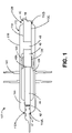
- FIG. 1 is a side cross-sectional schematic view of a cover unit including multiple types of stress control elements secured to a cable (not shown in cross-section) according to some embodiments of the invention.
- a cover system 101 includes a termination body or cover assembly, unit, body or sleeve 110 that includes multiple stress control elements and/or types thereof.
- the cover system 101 may be used to form a protected cable assembly including a terminated (or spliced) cable 40, a termination or connector 17, and the cover sleeve 110.
- the cover system 101 or a portion thereof is provided as a unitary cold shrinkable, tubular, elastomeric cover sleeve defining a cover sleeve through passage that is configured to receive the electrical cable 40.
- the cover sleeve 110 is a multilayer device that includes a first type of stress control element and a second type of stress control element that is different from the first type of stress control element.
- the cable 40 includes a primary electrical conductor 42, a polymeric insulation layer 44, a semiconductor layer 46, a metal electromagnetic radiation shield layer 48, and a jacket 50, with each component being concentrically surrounded by the next.
- the shield layer 48 includes a metal tape, foil, strip or sheath wrapped or wound (e.g., circumferentially or helically) about and fully circumferentially surrounding the semiconductor layer 46 along the length of the cable 40.
- the shield layer 48 may include individual concentric neutral wires longitudinally and/or helically wound about the semiconductor layer 46 along the length of the cable 40 and about a center axis of the cable that corresponds to the longitudinal center of the primary electrical conductor 42, for example.
- the primary electrical conductor 42 may be formed of any suitable electrically conductive materials such as copper (solid or stranded).
- the polymeric insulation layer 44 may be formed of any suitable electrically insulative material such as crosslinked polyethylene (XLPE) or EPR.
- XLPE crosslinked polyethylene
- EPR EPR
- the semiconductor layer 46 may be formed of any suitable semiconductor material such as carbon black with silicone.
- the semiconductor layer has a thickness in the range of from about 0.76 to 1.78 mm (0.030 to 0.070 inch), however, such embodiments are non-limiting.
- the shield layer 48 may be formed of any suitable material such as copper.
- the jacket 50 may be formed of any suitable material such as EPDM rubber or PVC.
- the cable 40 is a medium-voltage or high-voltage (e.g., greater than about 40 kV) power transmission cable.
- the cable 40 has a size (outer diameter) in the range of from about 15 to 127 mm (0.6 to 5 inches).
- the cover sleeve 110 is a cold shrink cover, meaning that it can be shrunk or retracted about the substrate(s) without requiring the use of applied heat.
- the cover sleeve 110 includes an outer, electrically insulating sleeve or layer 120.
- the longitudinal center of the primary electrical conductor 42 may form a longitudinal axis which may be common to a longitudinal axis of the cover sleeve 110 when installed on the electrical cable 40.
- the cover sleeve 110 has opposed inner and outer surfaces 114 and 116, and opposed ends 110A, 110B.
- the cover sleeve 110 is tubular and defines an axially extending conductor through passage 112C that communicates with opposed end openings 112A, 112B.
- the cover sleeve 110 may include integral sheds 142.
- the electrically insulating layer 120 forms the outer surface 116 and has the opposed inner surface 114.
- the electrically insulating layer 120 is tubular and may define an axially extending conductor through passage that communicates with the opposed end openings 112A, 112B.
- the electrically insulating layer 120 can be formed of any suitable elastically expandable, dielectric or electrically insulating material. According to some embodiments, the electrically insulating layer 120 has a Modulus at 100 percent elongation (M100) in the range of from about 0.13 to 0.80 MPa. According to some embodiments, the electrically insulating layer 120 is formed of an elastomeric material. According to some embodiments, the electrically insulating layer 120 is formed of ethylene propylene diene monomer (EPDM) rubber, liquid silicone rubber (LSR), ethylene propylene rubber (EPR), neoprene, silicone rubber, or other suitable rubber.
- EPDM ethylene propylene diene monomer
- LSR liquid silicone rubber
- EPR ethylene propylene rubber
- neoprene silicone rubber
- cover sleeve 110 is multilayered and includes multiple types of stress control elements that may smooth the abrupt change in the electrical field that can cause electrical stress at the terminal edge 46A of the cable semiconductor layer 46. Such electrical stress, if not addressed by a stress control element, may cause the insulation of the cable 40 to breakdown.
- a first type of stress control element includes a geometric stress relief element such as, for example, a stress cone 130.
- a stress cone may include an integral electrically conductive (e.g., semiconductive) stress element layer or cone 130.
- the layers 120 and 130 are thus formed of electrically and functionally dissimilar materials.
- the stress cone 130 may be a layer that is a generally tubular sleeve that extends axially such that the inner surface 132 of the stress cone 130 defines an axially extending conductor through passage that defines, in part, the passage 112C.
- the stress cone 130 may be formed of a suitable electrically conductive, elastically expandable material.
- the stress cone 130 is formed of a material having a Modulus at 100 percent elongation (M100) in the range of from about 0.15 to 0.90 MPa.
- the stress cone 130 is formed of an elastomeric material.
- the stress cone 130 is formed of liquid silicone rubber (LSR), EPDM rubber, or ethylene propylene rubber (EPR).
- the elastomeric material may include an electrically conductive filler material such as carbon black, for example.
- a second type of stress control element is a capacitive stress relief element being in the form of a high-K tube 150 which is also referred to as a high-K layer 150.
- the high-K tube 150 includes a high-K material such as EPDM rubber. Some embodiments provide that the high-K tube has a dielectric constant that is greater than about 12. The length of the high K tube 150 may be determined by the dielectric constant of the tube. As illustrated, the high-K tube 150 is bonded to an inner surface of the electrically insulating layer 120. Additionally, the stress cone 130 may be bonded to an inner surface of the high-K tube 150 and/or embedded in and/or integral to the high-K tube 150.
- the stress cone 130 and the high-K tube 150 may be integrally formed in the cover sleeve 110 to provide a unitary structure that includes multiple layers that include multiple types of stress control elements.
- the stress control elements e.g., stress cone and high-K tube
- the stress control elements may have different shapes than illustrated in FIG. 1 .
- the stress control element 130 and the high-K tube 150 in combination serve to taper the electrical field lines by forcing them to follow the contour of the stress cone 130 and to reduce the concentration of the field lines at the terminal edge 46A.
- the cover sleeve 110 may be formed by any suitable method and apparatus.
- the stress cone 130 is molded and the high-K layer 150 is molded around the stress cone 130.
- the electrically insulating layer 120 may then be molded around the high-K layer 150 and stress cone 130.
- a multiple-layer unitary cold shrinkable, elastomeric cover sleeve that includes two types of stress relief elements may be formed.
- the first type of stress relief element is radially disposed between the cable 40 and the second type of stress relief element.
- sealants may also be included and/or implemented when practicing embodiments herein including sealants, tapes, clamps, straps, retention members, and/or positioning devices as needed.
- FIG. 2 is a side cross-sectional schematic view of a cover unit including multiple types of stress control elements secured to a cable included for background information.
- reference numerals that are the same as those of FIG. 1 denote the same elements, and thus, their detailed description may be omitted.
- a cover system 102 includes a cover sleeve 110 that includes multiple stress control elements and/or types thereof. Similar to the cover system 101 illustrated in FIG. 1 , the cover sleeve 110 is a multilayer cover that includes the stress cone 130, the high-K tube 150 and the electrically insulating layer 120. In contrast with the cover system 101 illustrated in FIG. 1 , the cover sleeve 110 of FIG. 2 provides that the stress cone 130 may be bonded to an inner surface of the electrically insulating layer 120. Additionally, the electrically insulating layer 120 may be bonded to an outer surface of the high-K tube 150 and/or embedded in and/or integral to the high-K tube 150. In this manner the stress cone 130 and the high-K tube 150 may be integrally formed in the cover sleeve 110 to provide a unitary structure that includes multiple layers that include multiple types of stress control elements.
- the high-K tube 150 may be formed to be on a portion of an inner surface of the stress cone 130.
- the high-K tube 150 may include an inner surface having a portion that contacts a portion of the semiconductor layer 46, and the stress cone 130 may include an inner surface having a portion that contacts another portion of the semiconductor layer 46.
- the cover system 102 may be used to form a protected cable assembly including a terminated (or spliced) cable 40, a termination or connector 17, and the cover sleeve 110.
- the cover system 102 or a portion thereof is provided as a unitary cold shrinkable, tubular, elastomeric cover sleeve defining a cover sleeve through passage that is configured to receive the electrical cable 40.
- the cover sleeve 110 may be a multilayer device that includes a first type of stress control element and a second type of stress control element that is different from the first type of stress control element.
- FIG. 3 is a side cross-sectional schematic view of a pre-expanded cover unit including multiple types of stress control elements and a holdout positioned on a cable according to some embodiments of the invention.
- reference numerals that are the same as those of FIGS. 1 and 2 denote the same elements, and thus, their detailed description may be omitted.
- the cover sleeve 110 may be provided as a pre-expanded cover unit.
- the cover system 103 includes a holdout 140 that is configured to retain the cover sleeve 110 in an expanded position.
- the cover sleeve 110 is mounted on the holdout 140 in an expanded state or position.
- the holdout 140 is a disintegratable or collapsible rigid tube.
- the holdout 140 is what is commonly referred to as a spiral holdout or core.
- the holdout 140 is a non-spiral core that may be removable and/or retractable.
- the holdout 140 may include a tubular, cylindrical member or body.
- the holdout 140 may include through passage or bore 142C communicating with opposed end openings thereof.
- the holdout 140 includes a continuous, flexible ribbon or strip that is helically wound to form a series of looped strip segments. The segments may be releasably or detachably joined to the respective adjacent segments along their edges to thereby form or constitute the holdout body in the form of a rigid, tubular cylinder.
- suitable holdouts may include holdouts as disclosed in U.S. Patent No. 5,925,427 to Sadlo et al. , U.S. Patent No. 5,944,929 to Vallauri et al. and U.S. Patent No. 5,670,223 to Sadlo et al.
- the holdout 140 can be formed of any suitable material. According to some embodiments, the holdout 140 is formed of a semi-rigid polymeric material. According to some embodiments, the holdout 140 is formed of high density polyethylene (HDPE), low density polyethylene (LDPE), polypropylene, ABS, or PVC.
- HDPE high density polyethylene
- LDPE low density polyethylene
- ABS polypropylene
- PVC PVC
- the cover sleeve 110 When mounted on the holdout 140, the cover sleeve 110 is maintained in an elastically radially expanded state or position. According to some embodiments, in the expanded state the cover sleeve 110 is expanded in the range of from about 200 to 400 percent of its relaxed diameter ( i.e ., not on a substrate). As a result, the cover sleeve 110 of the pre-expanded unit 102 will exert a radially compressive pressure or load on the holdout 140.
- the cover sleeve 110 shrinks towards the cable 40.
- the relaxed inner diameter of the cover sleeve 110 is less than at least the outer diameter of the jacket 50 and the outer diameter of the semiconductor layer 46. Therefore, the cover sleeve 110 exerts a persistent radially inwardly compressive or clamping force or pressure (due to elastic tension) onto the cable 40.
- the cover sleeve 110 may thereby effect a liquid tight seal at the interface between the cable 40 and the cover sleeve 110. This seal can protect the cable and the connection from the ingress of environmental moisture.
- the relaxed inner diameter of the cover sleeve 110 is between about 20 and 40 percent less than the smallest diameter cable upon which the cover sleeve 110 is intended to be installed.
- FIG. 2 While illustrated as including multi-layer arrangement similar to that discussed above regarding FIG. 1 , the multi-layer arrangement as illustrated in FIG. 2 and described above may be used in embodiments corresponding to FIG. 3 .
Landscapes
- Engineering & Computer Science (AREA)
- Manufacturing & Machinery (AREA)
- Power Engineering (AREA)
- Cable Accessories (AREA)
- Flexible Shafts (AREA)
- Measuring Pulse, Heart Rate, Blood Pressure Or Blood Flow (AREA)
- Buffer Packaging (AREA)
Claims (8)
- Dispositif à unité de revêtement (101) pour la terminaison d'un câble électrique (40), le dispositif comprenant :
une gaine de revêtement élastomère, tubulaire, unitaire rétrécissable à froid (110) définissant un passage traversant de gaine de revêtement (112C) qui est configuré pour recevoir le câble électrique, la gaine de revêtement comprenant :un premier type d'élément de commande de contrainte (130) qui comprend un élément de détente géométrique des contraintes (130) et l'élément de détente géométrique des contraintes comprenant un cône de contrainte (130) qui inclut une portion électriquement conductrice et/ou semi-conductrice qui est configurée pour se mettre en prise conductivement avec une couche semi-conductrice (46) du câble électrique (40), etune couche extérieure électriquement isolante (120),caractérisé parun deuxième type d'élément de commande de contrainte (150) qui est différent du premier type d'élément de commande de contrainte et qui est disposé radialement autour du premier type d'élément de commande de contrainte, le deuxième type d'élément de commande de contrainte étant une couche à K élevé (150) et étant configuré pour se mettre en prise conductivement avec la couche semi-conductrice (46) du câble électrique (40) lorsqu'elle est installée sur celui-ci et le deuxième type d'élément de commande de contrainte (150) étant liaisonné à la surface intérieure de la couche extérieure électriquement isolante (120) . - Dispositif selon la revendication 1, dans lequel le deuxième type d'élément de commande de contrainte comprend un élément de détente des contraintes à constante diélectrique élevée (150).
- Dispositif selon la revendication 1, dans lequel la couche à K élevé (150) comprend des particules de carbone qui sont incorporées dans celle-ci.
- Dispositif selon la revendication 1, comprenant en outre un dispositif de retenue (140) qui maintient la gaine de revêtement (110) dans un état expansé dans lequel la gaine de revêtement est expansée élastiquement et lorsqu'il est enlevé, permet à la gaine de revêtement de se contracter radialement jusqu'à un état contracté autour du câble électrique (40),
dans lequel le dispositif de retenue (140) est un dispositif de retenue amovible qui est monté au sein du passage traversant de gaine de revêtement (112C) et configuré pour être enlevé de celui-ci. - Dispositif selon la revendication 1, dans lequel la couche électriquement isolante (120) comprend un matériau élastomère qui inclut au moins une substance parmi caoutchouc monomère éthylène-propylène (EPDM), silicone, caoutchouc polyuréthanne, copolymère styrène-butadiène, polychloroprène, caoutchouc nitrile, caoutchouc butyle et/ou caoutchouc de polysulfure.
- Dispositif selon la revendication 1, dans lequel le premier type d'élément de commande de contrainte (130) est liaisonné ou fait corps avec le deuxième type d'élément de commande de contrainte (150), le premier type d'élément de commande de contrainte et le deuxième type d'élément de commande de contrainte étant formés d'un seul tenant dans la gaine de revêtement (110) afin de fournir une structure unitaire qui inclut des couches multiples qui incluent de multiples types d'éléments de commande de contrainte.
- Dispositif selon la revendication 1, dans lequel la couche extérieure électriquement isolante (120) est disposée radialement autour du deuxième type d'élément de commande de contrainte (150).
- Procédé d'installation d'une gaine de revêtement (110) sur un câble électrique (40), le procédé comprenant les opérations de :
fourniture :
d'une gaine de revêtement élastomère, tubulaire, unitaire rétrécissable à froid (110) définissant un passage traversant de gaine de revêtement (112C) qui est configuré pour recevoir le câble électrique, la gaine de revêtement comprenant :un premier type d'élément de commande de contrainte (130) qui comprend un élément de détente géométrique des contraintes (130) et l'élément de détente géométrique des contraintes comprenant un cône de contrainte (130) qui inclut une portion électriquement conductrice et/ou semi-conductrice qui est configurée pour se mettre en prise conductivement avec une couche semi-conductrice (46) du câble électrique (40),un deuxième type d'élément de commande de contrainte (150) qui est différent du premier type d'élément de commande de contrainte et qui est disposé radialement autour du premier type d'élément de commande de contrainte, le deuxième type d'élément de commande de contrainte étant une couche à K élevé (150) et étant configuré pour se mettre en prise conductivement avec la couche semi-conductrice (46) du câble électrique (40) lorsqu'elle est installée sur celui-ci, etune couche extérieure électriquement isolante (120), le deuxième type d'élément de commande de contrainte (150) étant liaisonné à la couche extérieure électriquement isolante (120) ;etun dispositif de retenue (140) qui maintient la gaine de revêtement (110) dans un état expansé dans lequel la gaine de revêtement est expansée élastiquement et lorsqu'il est enlevé, permet à cette gaine de revêtement de se contracter radialement jusqu'à un état contracté autour du câble électrique (40) ;positionnement du dispositif de retenue (140) et de la gaine de revêtement (110) autour du câble électrique (40) ; etenlèvement du dispositif de retenue (140) depuis la gaine de revêtement (110) afin d'amener la gaine de revêtement à se contracter radialement sur le câble électrique (40).
Applications Claiming Priority (2)
| Application Number | Priority Date | Filing Date | Title |
|---|---|---|---|
| US15/135,781 US9870848B2 (en) | 2016-04-22 | 2016-04-22 | Multiple stress control device for cable accessories and methods and systems including same |
| PCT/US2017/025872 WO2017184330A1 (fr) | 2016-04-22 | 2017-04-04 | Dispositif de commande de contrainte multiple pour accessoires de câble et procédés ainsi que systèmes le comprenant |
Publications (2)
| Publication Number | Publication Date |
|---|---|
| EP3446385A1 EP3446385A1 (fr) | 2019-02-27 |
| EP3446385B1 true EP3446385B1 (fr) | 2022-09-07 |
Family
ID=58633092
Family Applications (1)
| Application Number | Title | Priority Date | Filing Date |
|---|---|---|---|
| EP17719761.3A Active EP3446385B1 (fr) | 2016-04-22 | 2017-04-04 | Dispositif de commande de contrainte multiple pour accessoires de câble et procédés ainsi que systèmes le comprenant |
Country Status (5)
| Country | Link |
|---|---|
| US (1) | US9870848B2 (fr) |
| EP (1) | EP3446385B1 (fr) |
| CN (1) | CN109478772B (fr) |
| ES (1) | ES2931208T3 (fr) |
| WO (1) | WO2017184330A1 (fr) |
Families Citing this family (2)
| Publication number | Priority date | Publication date | Assignee | Title |
|---|---|---|---|---|
| DE102018116416A1 (de) * | 2018-07-06 | 2020-01-09 | Nkt Gmbh & Co. Kg | Verbindungsmuffe |
| US11908594B2 (en) | 2020-08-20 | 2024-02-20 | Te Connectivity Solutions Gmbh | Method for monitoring an electrical cable accessory system |
Citations (1)
| Publication number | Priority date | Publication date | Assignee | Title |
|---|---|---|---|---|
| US20140338953A1 (en) * | 2013-05-14 | 2014-11-20 | Tyco Electronics Raychem Gmbh | Joint bodies and methods for covering electrical cables and connections |
Family Cites Families (29)
| Publication number | Priority date | Publication date | Assignee | Title |
|---|---|---|---|---|
| US3585274A (en) | 1969-09-15 | 1971-06-15 | Minnesota Mining & Mfg | Relief of dielectric stress in high voltage cable connections |
| US3796821A (en) * | 1972-10-06 | 1974-03-12 | G & W Electric Speciality Co | High voltage cable termination |
| CA1277371C (fr) * | 1984-07-02 | 1990-12-04 | Graham J. Clarke | Dispositif a haute tension |
| US4822952A (en) * | 1985-08-21 | 1989-04-18 | Cable Technology Laboratories, Inc. | Electrical cable joint and electrical cable termination and methods of making same |
| GB8630335D0 (en) | 1986-12-19 | 1987-01-28 | Raychem Gmbh | Hv cables |
| NL8901138A (nl) | 1989-05-03 | 1990-12-03 | Nkf Kabel Bv | Insteekverbinding voor hoogspanningskunststofkabels. |
| DE3943296C2 (de) | 1989-12-29 | 1994-08-11 | Minnesota Mining & Mfg | Muffe zum Einhüllen einer Verbindung oder eines Endes eines Elektrokabels |
| US5670223A (en) | 1995-02-06 | 1997-09-23 | Minnesota Mining And Manufacturing Company | Support core ribbon for cold-shrink tube |
| US5925427A (en) | 1995-02-06 | 1999-07-20 | Minnesota Mining And Manufacturing Company | Support core ribbon for cold-shrink tube |
| IT1275976B1 (it) | 1995-03-27 | 1997-10-24 | Pirelli Cavi S P A Ora Pirelli | Supporto per un manicotto elastico |
| US5801332A (en) * | 1995-08-31 | 1998-09-01 | Minnesota Mining And Manufacturing Company | Elastically recoverable silicone splice cover |
| US6455779B1 (en) * | 1995-10-11 | 2002-09-24 | Michael G. Jones | Dual element cable connection cover |
| ES2151990T3 (es) | 1995-12-23 | 2001-01-16 | Minnesota Mining & Mfg | Adaptador de cable universal, junta de cable que usa el adaptador y metodo para fabricarlo. |
| US5844170A (en) | 1996-03-01 | 1998-12-01 | Minnesota Mining And Manufacturing Company | Closure with flowable material and reinforcing core |
| WO1999021259A1 (fr) | 1997-10-22 | 1999-04-29 | Minnesota Mining And Manufacturing Company | Epissure perfectionnee de branchement moyenne tension, et procede associe |
| EP0920102B1 (fr) * | 1997-11-28 | 2002-03-06 | Nexans | Protection extérieure à interruption de blindage pour jonction de câble haute tension |
| US6103975A (en) | 1998-06-29 | 2000-08-15 | 3M Innovative Properties Company | Pre-assembled electrical splice component |
| TW588488B (en) * | 2001-11-27 | 2004-05-21 | Fujikura Ltd | Connecting structure for electrical connection power cable, connecting device and manufacturing method of connecting device |
| JP4158904B2 (ja) | 2003-04-18 | 2008-10-01 | 古河電気工業株式会社 | 常温収縮型ゴムユニット |
| US7251881B2 (en) | 2004-10-14 | 2007-08-07 | 3M Innovative Properties Company | Method of delivering geometric stress relief element to high voltage cable terminations |
| US7476114B1 (en) * | 2008-05-05 | 2009-01-13 | Tyco Electronics Corporation | Cover assemblies for cables and electrical connections and methods for making and using the same |
| US7901243B1 (en) * | 2010-03-30 | 2011-03-08 | Tyco Electronics Corporation | Methods and systems for forming a protected disconnectable joint assembly |
| EP2466708A1 (fr) | 2010-12-17 | 2012-06-20 | 3M Innovative Properties Company | Dispositif de contrôle de contrainte |
| DK2608338T3 (en) | 2011-12-21 | 2014-02-17 | 3M Innovative Properties Co | Terminal connector for a power cable |
| US8889989B2 (en) * | 2012-09-14 | 2014-11-18 | Tyco Electronics Corporation | Elastomeric cable adapters for power transmission cables and cover assemblies and methods including the same |
| US9224520B2 (en) * | 2012-12-03 | 2015-12-29 | Tyco Electronics Corporation | Cover assemblies and methods for covering electrical cables and connections |
| EP2747227B1 (fr) | 2012-12-21 | 2017-03-01 | Tyco Electronics Raychem GmbH | Manchon tubulaire thermorétractable multicouche avec éléments de commande de contrainte |
| US9504195B2 (en) | 2014-05-16 | 2016-11-22 | Tyco Electronics Corporation | Cover assemblies, kits and methods for covering electrical cables and connections |
| CN104882844B (zh) * | 2015-05-07 | 2018-02-09 | 深圳市沃尔核材股份有限公司 | 一种热缩复合应力管及其生产方法 |
-
2016
- 2016-04-22 US US15/135,781 patent/US9870848B2/en active Active
-
2017
- 2017-04-04 CN CN201780038623.XA patent/CN109478772B/zh active Active
- 2017-04-04 EP EP17719761.3A patent/EP3446385B1/fr active Active
- 2017-04-04 ES ES17719761T patent/ES2931208T3/es active Active
- 2017-04-04 WO PCT/US2017/025872 patent/WO2017184330A1/fr active Application Filing
Patent Citations (1)
| Publication number | Priority date | Publication date | Assignee | Title |
|---|---|---|---|---|
| US20140338953A1 (en) * | 2013-05-14 | 2014-11-20 | Tyco Electronics Raychem Gmbh | Joint bodies and methods for covering electrical cables and connections |
Also Published As
| Publication number | Publication date |
|---|---|
| EP3446385A1 (fr) | 2019-02-27 |
| US9870848B2 (en) | 2018-01-16 |
| CN109478772A (zh) | 2019-03-15 |
| ES2931208T3 (es) | 2022-12-27 |
| US20170309376A1 (en) | 2017-10-26 |
| WO2017184330A1 (fr) | 2017-10-26 |
| CN109478772B (zh) | 2020-08-21 |
Similar Documents
| Publication | Publication Date | Title |
|---|---|---|
| US10411456B2 (en) | Cover assemblies and methods for covering electrical cables and connections | |
| US9504195B2 (en) | Cover assemblies, kits and methods for covering electrical cables and connections | |
| US7476114B1 (en) | Cover assemblies for cables and electrical connections and methods for making and using the same | |
| US8030570B2 (en) | Cover assemblies for cables and electrical connections and methods for making and using the same | |
| US8889989B2 (en) | Elastomeric cable adapters for power transmission cables and cover assemblies and methods including the same | |
| US7858883B2 (en) | Methods and kits for covering electrical cables and connections | |
| EP3350896B1 (fr) | Ensembles de gaine et procédés de gainage de câbles et connexions électriques | |
| US9960576B2 (en) | Cover assemblies for cables and electrical connections and methods for making and using the same | |
| US10283878B2 (en) | Neutral conductor connection protection devices and cover assembly kits, electrical connections and methods including same | |
| EP3446385B1 (fr) | Dispositif de commande de contrainte multiple pour accessoires de câble et procédés ainsi que systèmes le comprenant | |
| US10389103B2 (en) | Breakout boot assemblies and methods for covering electrical cables and connections |
Legal Events
| Date | Code | Title | Description |
|---|---|---|---|
| STAA | Information on the status of an ep patent application or granted ep patent |
Free format text: STATUS: UNKNOWN |
|
| STAA | Information on the status of an ep patent application or granted ep patent |
Free format text: STATUS: THE INTERNATIONAL PUBLICATION HAS BEEN MADE |
|
| PUAI | Public reference made under article 153(3) epc to a published international application that has entered the european phase |
Free format text: ORIGINAL CODE: 0009012 |
|
| STAA | Information on the status of an ep patent application or granted ep patent |
Free format text: STATUS: REQUEST FOR EXAMINATION WAS MADE |
|
| 17P | Request for examination filed |
Effective date: 20181115 |
|
| AK | Designated contracting states |
Kind code of ref document: A1 Designated state(s): AL AT BE BG CH CY CZ DE DK EE ES FI FR GB GR HR HU IE IS IT LI LT LU LV MC MK MT NL NO PL PT RO RS SE SI SK SM TR |
|
| AX | Request for extension of the european patent |
Extension state: BA ME |
|
| DAV | Request for validation of the european patent (deleted) | ||
| DAX | Request for extension of the european patent (deleted) | ||
| STAA | Information on the status of an ep patent application or granted ep patent |
Free format text: STATUS: EXAMINATION IS IN PROGRESS |
|
| 17Q | First examination report despatched |
Effective date: 20190905 |
|
| STAA | Information on the status of an ep patent application or granted ep patent |
Free format text: STATUS: EXAMINATION IS IN PROGRESS |
|
| STAA | Information on the status of an ep patent application or granted ep patent |
Free format text: STATUS: EXAMINATION IS IN PROGRESS |
|
| GRAP | Despatch of communication of intention to grant a patent |
Free format text: ORIGINAL CODE: EPIDOSNIGR1 |
|
| STAA | Information on the status of an ep patent application or granted ep patent |
Free format text: STATUS: GRANT OF PATENT IS INTENDED |
|
| INTG | Intention to grant announced |
Effective date: 20220525 |
|
| GRAS | Grant fee paid |
Free format text: ORIGINAL CODE: EPIDOSNIGR3 |
|
| GRAA | (expected) grant |
Free format text: ORIGINAL CODE: 0009210 |
|
| STAA | Information on the status of an ep patent application or granted ep patent |
Free format text: STATUS: THE PATENT HAS BEEN GRANTED |
|
| AK | Designated contracting states |
Kind code of ref document: B1 Designated state(s): AL AT BE BG CH CY CZ DE DK EE ES FI FR GB GR HR HU IE IS IT LI LT LU LV MC MK MT NL NO PL PT RO RS SE SI SK SM TR |
|
| REG | Reference to a national code |
Ref country code: GB Ref legal event code: FG4D |
|
| REG | Reference to a national code |
Ref country code: CH Ref legal event code: EP Ref country code: AT Ref legal event code: REF Ref document number: 1517851 Country of ref document: AT Kind code of ref document: T Effective date: 20220915 |
|
| REG | Reference to a national code |
Ref country code: DE Ref legal event code: R096 Ref document number: 602017061482 Country of ref document: DE |
|
| REG | Reference to a national code |
Ref country code: IE Ref legal event code: FG4D |
|
| REG | Reference to a national code |
Ref country code: NO Ref legal event code: T2 Effective date: 20220907 |
|
| REG | Reference to a national code |
Ref country code: SE Ref legal event code: TRGR |
|
| REG | Reference to a national code |
Ref country code: LT Ref legal event code: MG9D Ref country code: ES Ref legal event code: FG2A Ref document number: 2931208 Country of ref document: ES Kind code of ref document: T3 Effective date: 20221227 |
|
| REG | Reference to a national code |
Ref country code: NL Ref legal event code: MP Effective date: 20220907 |
|
| PG25 | Lapsed in a contracting state [announced via postgrant information from national office to epo] |
Ref country code: RS Free format text: LAPSE BECAUSE OF FAILURE TO SUBMIT A TRANSLATION OF THE DESCRIPTION OR TO PAY THE FEE WITHIN THE PRESCRIBED TIME-LIMIT Effective date: 20220907 Ref country code: LV Free format text: LAPSE BECAUSE OF FAILURE TO SUBMIT A TRANSLATION OF THE DESCRIPTION OR TO PAY THE FEE WITHIN THE PRESCRIBED TIME-LIMIT Effective date: 20220907 Ref country code: LT Free format text: LAPSE BECAUSE OF FAILURE TO SUBMIT A TRANSLATION OF THE DESCRIPTION OR TO PAY THE FEE WITHIN THE PRESCRIBED TIME-LIMIT Effective date: 20220907 Ref country code: FI Free format text: LAPSE BECAUSE OF FAILURE TO SUBMIT A TRANSLATION OF THE DESCRIPTION OR TO PAY THE FEE WITHIN THE PRESCRIBED TIME-LIMIT Effective date: 20220907 |
|
| REG | Reference to a national code |
Ref country code: AT Ref legal event code: MK05 Ref document number: 1517851 Country of ref document: AT Kind code of ref document: T Effective date: 20220907 |
|
| PG25 | Lapsed in a contracting state [announced via postgrant information from national office to epo] |
Ref country code: HR Free format text: LAPSE BECAUSE OF FAILURE TO SUBMIT A TRANSLATION OF THE DESCRIPTION OR TO PAY THE FEE WITHIN THE PRESCRIBED TIME-LIMIT Effective date: 20220907 Ref country code: GR Free format text: LAPSE BECAUSE OF FAILURE TO SUBMIT A TRANSLATION OF THE DESCRIPTION OR TO PAY THE FEE WITHIN THE PRESCRIBED TIME-LIMIT Effective date: 20221208 |
|
| PG25 | Lapsed in a contracting state [announced via postgrant information from national office to epo] |
Ref country code: SM Free format text: LAPSE BECAUSE OF FAILURE TO SUBMIT A TRANSLATION OF THE DESCRIPTION OR TO PAY THE FEE WITHIN THE PRESCRIBED TIME-LIMIT Effective date: 20220907 Ref country code: RO Free format text: LAPSE BECAUSE OF FAILURE TO SUBMIT A TRANSLATION OF THE DESCRIPTION OR TO PAY THE FEE WITHIN THE PRESCRIBED TIME-LIMIT Effective date: 20220907 Ref country code: PT Free format text: LAPSE BECAUSE OF FAILURE TO SUBMIT A TRANSLATION OF THE DESCRIPTION OR TO PAY THE FEE WITHIN THE PRESCRIBED TIME-LIMIT Effective date: 20230109 Ref country code: CZ Free format text: LAPSE BECAUSE OF FAILURE TO SUBMIT A TRANSLATION OF THE DESCRIPTION OR TO PAY THE FEE WITHIN THE PRESCRIBED TIME-LIMIT Effective date: 20220907 Ref country code: AT Free format text: LAPSE BECAUSE OF FAILURE TO SUBMIT A TRANSLATION OF THE DESCRIPTION OR TO PAY THE FEE WITHIN THE PRESCRIBED TIME-LIMIT Effective date: 20220907 |
|
| PG25 | Lapsed in a contracting state [announced via postgrant information from national office to epo] |
Ref country code: SK Free format text: LAPSE BECAUSE OF FAILURE TO SUBMIT A TRANSLATION OF THE DESCRIPTION OR TO PAY THE FEE WITHIN THE PRESCRIBED TIME-LIMIT Effective date: 20220907 Ref country code: PL Free format text: LAPSE BECAUSE OF FAILURE TO SUBMIT A TRANSLATION OF THE DESCRIPTION OR TO PAY THE FEE WITHIN THE PRESCRIBED TIME-LIMIT Effective date: 20220907 Ref country code: IS Free format text: LAPSE BECAUSE OF FAILURE TO SUBMIT A TRANSLATION OF THE DESCRIPTION OR TO PAY THE FEE WITHIN THE PRESCRIBED TIME-LIMIT Effective date: 20230107 Ref country code: EE Free format text: LAPSE BECAUSE OF FAILURE TO SUBMIT A TRANSLATION OF THE DESCRIPTION OR TO PAY THE FEE WITHIN THE PRESCRIBED TIME-LIMIT Effective date: 20220907 |
|
| PGFP | Annual fee paid to national office [announced via postgrant information from national office to epo] |
Ref country code: SE Payment date: 20230310 Year of fee payment: 7 |
|
| REG | Reference to a national code |
Ref country code: DE Ref legal event code: R097 Ref document number: 602017061482 Country of ref document: DE |
|
| PG25 | Lapsed in a contracting state [announced via postgrant information from national office to epo] |
Ref country code: NL Free format text: LAPSE BECAUSE OF FAILURE TO SUBMIT A TRANSLATION OF THE DESCRIPTION OR TO PAY THE FEE WITHIN THE PRESCRIBED TIME-LIMIT Effective date: 20220907 Ref country code: AL Free format text: LAPSE BECAUSE OF FAILURE TO SUBMIT A TRANSLATION OF THE DESCRIPTION OR TO PAY THE FEE WITHIN THE PRESCRIBED TIME-LIMIT Effective date: 20220907 |
|
| PLBE | No opposition filed within time limit |
Free format text: ORIGINAL CODE: 0009261 |
|
| STAA | Information on the status of an ep patent application or granted ep patent |
Free format text: STATUS: NO OPPOSITION FILED WITHIN TIME LIMIT |
|
| PG25 | Lapsed in a contracting state [announced via postgrant information from national office to epo] |
Ref country code: DK Free format text: LAPSE BECAUSE OF FAILURE TO SUBMIT A TRANSLATION OF THE DESCRIPTION OR TO PAY THE FEE WITHIN THE PRESCRIBED TIME-LIMIT Effective date: 20220907 |
|
| PGFP | Annual fee paid to national office [announced via postgrant information from national office to epo] |
Ref country code: NO Payment date: 20230412 Year of fee payment: 7 Ref country code: ES Payment date: 20230512 Year of fee payment: 7 |
|
| 26N | No opposition filed |
Effective date: 20230608 |
|
| PG25 | Lapsed in a contracting state [announced via postgrant information from national office to epo] |
Ref country code: SI Free format text: LAPSE BECAUSE OF FAILURE TO SUBMIT A TRANSLATION OF THE DESCRIPTION OR TO PAY THE FEE WITHIN THE PRESCRIBED TIME-LIMIT Effective date: 20220907 |
|
| REG | Reference to a national code |
Ref country code: NO Ref legal event code: CREP Representative=s name: BRYN AARFLOT AS, STORTINGSGATA 8, 0161 OSLO, NORGE Ref country code: NO Ref legal event code: CHAD Owner name: TE CONNECTIVITY SOLUTIONS GMBH, CH |
|
| REG | Reference to a national code |
Ref country code: DE Ref legal event code: R119 Ref document number: 602017061482 Country of ref document: DE |
|
| REG | Reference to a national code |
Ref country code: CH Ref legal event code: PL |
|
| GBPC | Gb: european patent ceased through non-payment of renewal fee |
Effective date: 20230404 |
|
| PG25 | Lapsed in a contracting state [announced via postgrant information from national office to epo] |
Ref country code: LU Free format text: LAPSE BECAUSE OF NON-PAYMENT OF DUE FEES Effective date: 20230404 |
|
| REG | Reference to a national code |
Ref country code: BE Ref legal event code: MM Effective date: 20230430 |
|
| PG25 | Lapsed in a contracting state [announced via postgrant information from national office to epo] |
Ref country code: MC Free format text: LAPSE BECAUSE OF FAILURE TO SUBMIT A TRANSLATION OF THE DESCRIPTION OR TO PAY THE FEE WITHIN THE PRESCRIBED TIME-LIMIT Effective date: 20220907 |
|
| PG25 | Lapsed in a contracting state [announced via postgrant information from national office to epo] |
Ref country code: GB Free format text: LAPSE BECAUSE OF NON-PAYMENT OF DUE FEES Effective date: 20230404 |
|
| PG25 | Lapsed in a contracting state [announced via postgrant information from national office to epo] |
Ref country code: MC Free format text: LAPSE BECAUSE OF FAILURE TO SUBMIT A TRANSLATION OF THE DESCRIPTION OR TO PAY THE FEE WITHIN THE PRESCRIBED TIME-LIMIT Effective date: 20220907 Ref country code: LI Free format text: LAPSE BECAUSE OF NON-PAYMENT OF DUE FEES Effective date: 20230430 Ref country code: GB Free format text: LAPSE BECAUSE OF NON-PAYMENT OF DUE FEES Effective date: 20230404 Ref country code: FR Free format text: LAPSE BECAUSE OF NON-PAYMENT OF DUE FEES Effective date: 20230430 Ref country code: DE Free format text: LAPSE BECAUSE OF NON-PAYMENT OF DUE FEES Effective date: 20231103 Ref country code: CH Free format text: LAPSE BECAUSE OF NON-PAYMENT OF DUE FEES Effective date: 20230430 |
|
| REG | Reference to a national code |
Ref country code: IE Ref legal event code: MM4A |
|
| PG25 | Lapsed in a contracting state [announced via postgrant information from national office to epo] |
Ref country code: BE Free format text: LAPSE BECAUSE OF NON-PAYMENT OF DUE FEES Effective date: 20230430 |
|
| PG25 | Lapsed in a contracting state [announced via postgrant information from national office to epo] |
Ref country code: IE Free format text: LAPSE BECAUSE OF NON-PAYMENT OF DUE FEES Effective date: 20230404 |
|
| PG25 | Lapsed in a contracting state [announced via postgrant information from national office to epo] |
Ref country code: IE Free format text: LAPSE BECAUSE OF NON-PAYMENT OF DUE FEES Effective date: 20230404 |