EP3445963B1 - Dual-fuel-kraftstoffeinspritzsystem für eine brennkraftmaschine - Google Patents
Dual-fuel-kraftstoffeinspritzsystem für eine brennkraftmaschine Download PDFInfo
- Publication number
- EP3445963B1 EP3445963B1 EP17721961.5A EP17721961A EP3445963B1 EP 3445963 B1 EP3445963 B1 EP 3445963B1 EP 17721961 A EP17721961 A EP 17721961A EP 3445963 B1 EP3445963 B1 EP 3445963B1
- Authority
- EP
- European Patent Office
- Prior art keywords
- liquid fuel
- dual
- fuel injection
- injection system
- fuel
- Prior art date
- Legal status (The legal status is an assumption and is not a legal conclusion. Google has not performed a legal analysis and makes no representation as to the accuracy of the status listed.)
- Active
Links
Images

Classifications
-
- F—MECHANICAL ENGINEERING; LIGHTING; HEATING; WEAPONS; BLASTING
- F02—COMBUSTION ENGINES; HOT-GAS OR COMBUSTION-PRODUCT ENGINE PLANTS
- F02D—CONTROLLING COMBUSTION ENGINES
- F02D19/00—Controlling engines characterised by their use of non-liquid fuels, pluralities of fuels, or non-fuel substances added to the combustible mixtures
- F02D19/06—Controlling engines characterised by their use of non-liquid fuels, pluralities of fuels, or non-fuel substances added to the combustible mixtures peculiar to engines working with pluralities of fuels, e.g. alternatively with light and heavy fuel oil, other than engines indifferent to the fuel consumed
- F02D19/0663—Details on the fuel supply system, e.g. tanks, valves, pipes, pumps, rails, injectors or mixers
- F02D19/0684—High pressure fuel injection systems; Details on pumps, rails or the arrangement of valves in the fuel supply and return systems
-
- F—MECHANICAL ENGINEERING; LIGHTING; HEATING; WEAPONS; BLASTING
- F02—COMBUSTION ENGINES; HOT-GAS OR COMBUSTION-PRODUCT ENGINE PLANTS
- F02D—CONTROLLING COMBUSTION ENGINES
- F02D19/00—Controlling engines characterised by their use of non-liquid fuels, pluralities of fuels, or non-fuel substances added to the combustible mixtures
- F02D19/06—Controlling engines characterised by their use of non-liquid fuels, pluralities of fuels, or non-fuel substances added to the combustible mixtures peculiar to engines working with pluralities of fuels, e.g. alternatively with light and heavy fuel oil, other than engines indifferent to the fuel consumed
- F02D19/0663—Details on the fuel supply system, e.g. tanks, valves, pipes, pumps, rails, injectors or mixers
- F02D19/0673—Valves; Pressure or flow regulators; Mixers
-
- F—MECHANICAL ENGINEERING; LIGHTING; HEATING; WEAPONS; BLASTING
- F02—COMBUSTION ENGINES; HOT-GAS OR COMBUSTION-PRODUCT ENGINE PLANTS
- F02M—SUPPLYING COMBUSTION ENGINES IN GENERAL WITH COMBUSTIBLE MIXTURES OR CONSTITUENTS THEREOF
- F02M21/00—Apparatus for supplying engines with non-liquid fuels, e.g. gaseous fuels stored in liquid form
- F02M21/02—Apparatus for supplying engines with non-liquid fuels, e.g. gaseous fuels stored in liquid form for gaseous fuels
- F02M21/0218—Details on the gaseous fuel supply system, e.g. tanks, valves, pipes, pumps, rails, injectors or mixers
- F02M21/0245—High pressure fuel supply systems; Rails; Pumps; Arrangement of valves
-
- F—MECHANICAL ENGINEERING; LIGHTING; HEATING; WEAPONS; BLASTING
- F02—COMBUSTION ENGINES; HOT-GAS OR COMBUSTION-PRODUCT ENGINE PLANTS
- F02M—SUPPLYING COMBUSTION ENGINES IN GENERAL WITH COMBUSTIBLE MIXTURES OR CONSTITUENTS THEREOF
- F02M43/00—Fuel-injection apparatus operating simultaneously on two or more fuels, or on a liquid fuel and another liquid, e.g. the other liquid being an anti-knock additive
-
- F—MECHANICAL ENGINEERING; LIGHTING; HEATING; WEAPONS; BLASTING
- F02—COMBUSTION ENGINES; HOT-GAS OR COMBUSTION-PRODUCT ENGINE PLANTS
- F02M—SUPPLYING COMBUSTION ENGINES IN GENERAL WITH COMBUSTIBLE MIXTURES OR CONSTITUENTS THEREOF
- F02M43/00—Fuel-injection apparatus operating simultaneously on two or more fuels, or on a liquid fuel and another liquid, e.g. the other liquid being an anti-knock additive
- F02M43/02—Pumps peculiar thereto
-
- F—MECHANICAL ENGINEERING; LIGHTING; HEATING; WEAPONS; BLASTING
- F02—COMBUSTION ENGINES; HOT-GAS OR COMBUSTION-PRODUCT ENGINE PLANTS
- F02M—SUPPLYING COMBUSTION ENGINES IN GENERAL WITH COMBUSTIBLE MIXTURES OR CONSTITUENTS THEREOF
- F02M43/00—Fuel-injection apparatus operating simultaneously on two or more fuels, or on a liquid fuel and another liquid, e.g. the other liquid being an anti-knock additive
- F02M43/04—Injectors peculiar thereto
-
- F—MECHANICAL ENGINEERING; LIGHTING; HEATING; WEAPONS; BLASTING
- F02—COMBUSTION ENGINES; HOT-GAS OR COMBUSTION-PRODUCT ENGINE PLANTS
- F02M—SUPPLYING COMBUSTION ENGINES IN GENERAL WITH COMBUSTIBLE MIXTURES OR CONSTITUENTS THEREOF
- F02M63/00—Other fuel-injection apparatus having pertinent characteristics not provided for in groups F02M39/00 - F02M57/00 or F02M67/00; Details, component parts, or accessories of fuel-injection apparatus, not provided for in, or of interest apart from, the apparatus of groups F02M39/00 - F02M61/00 or F02M67/00; Combination of fuel pump with other devices, e.g. lubricating oil pump
- F02M63/0012—Valves
- F02M63/0014—Valves characterised by the valve actuating means
- F02M63/0028—Valves characterised by the valve actuating means hydraulic
-
- F—MECHANICAL ENGINEERING; LIGHTING; HEATING; WEAPONS; BLASTING
- F02—COMBUSTION ENGINES; HOT-GAS OR COMBUSTION-PRODUCT ENGINE PLANTS
- F02M—SUPPLYING COMBUSTION ENGINES IN GENERAL WITH COMBUSTIBLE MIXTURES OR CONSTITUENTS THEREOF
- F02M21/00—Apparatus for supplying engines with non-liquid fuels, e.g. gaseous fuels stored in liquid form
- F02M21/02—Apparatus for supplying engines with non-liquid fuels, e.g. gaseous fuels stored in liquid form for gaseous fuels
- F02M21/0218—Details on the gaseous fuel supply system, e.g. tanks, valves, pipes, pumps, rails, injectors or mixers
- F02M21/023—Valves; Pressure or flow regulators in the fuel supply or return system
-
- F—MECHANICAL ENGINEERING; LIGHTING; HEATING; WEAPONS; BLASTING
- F02—COMBUSTION ENGINES; HOT-GAS OR COMBUSTION-PRODUCT ENGINE PLANTS
- F02M—SUPPLYING COMBUSTION ENGINES IN GENERAL WITH COMBUSTIBLE MIXTURES OR CONSTITUENTS THEREOF
- F02M21/00—Apparatus for supplying engines with non-liquid fuels, e.g. gaseous fuels stored in liquid form
- F02M21/02—Apparatus for supplying engines with non-liquid fuels, e.g. gaseous fuels stored in liquid form for gaseous fuels
- F02M21/0218—Details on the gaseous fuel supply system, e.g. tanks, valves, pipes, pumps, rails, injectors or mixers
- F02M21/0248—Injectors
-
- F—MECHANICAL ENGINEERING; LIGHTING; HEATING; WEAPONS; BLASTING
- F02—COMBUSTION ENGINES; HOT-GAS OR COMBUSTION-PRODUCT ENGINE PLANTS
- F02M—SUPPLYING COMBUSTION ENGINES IN GENERAL WITH COMBUSTIBLE MIXTURES OR CONSTITUENTS THEREOF
- F02M37/00—Apparatus or systems for feeding liquid fuel from storage containers to carburettors or fuel-injection apparatus; Arrangements for purifying liquid fuel specially adapted for, or arranged on, internal-combustion engines
- F02M37/0011—Constructional details; Manufacturing or assembly of elements of fuel systems; Materials therefor
- F02M37/0023—Valves in the fuel supply and return system
-
- F—MECHANICAL ENGINEERING; LIGHTING; HEATING; WEAPONS; BLASTING
- F02—COMBUSTION ENGINES; HOT-GAS OR COMBUSTION-PRODUCT ENGINE PLANTS
- F02M—SUPPLYING COMBUSTION ENGINES IN GENERAL WITH COMBUSTIBLE MIXTURES OR CONSTITUENTS THEREOF
- F02M47/00—Fuel-injection apparatus operated cyclically with fuel-injection valves actuated by fluid pressure
- F02M47/02—Fuel-injection apparatus operated cyclically with fuel-injection valves actuated by fluid pressure of accumulator-injector type, i.e. having fuel pressure of accumulator tending to open, and fuel pressure in other chamber tending to close, injection valves and having means for periodically releasing that closing pressure
-
- Y—GENERAL TAGGING OF NEW TECHNOLOGICAL DEVELOPMENTS; GENERAL TAGGING OF CROSS-SECTIONAL TECHNOLOGIES SPANNING OVER SEVERAL SECTIONS OF THE IPC; TECHNICAL SUBJECTS COVERED BY FORMER USPC CROSS-REFERENCE ART COLLECTIONS [XRACs] AND DIGESTS
- Y02—TECHNOLOGIES OR APPLICATIONS FOR MITIGATION OR ADAPTATION AGAINST CLIMATE CHANGE
- Y02T—CLIMATE CHANGE MITIGATION TECHNOLOGIES RELATED TO TRANSPORTATION
- Y02T10/00—Road transport of goods or passengers
- Y02T10/10—Internal combustion engine [ICE] based vehicles
- Y02T10/30—Use of alternative fuels, e.g. biofuels
Definitions
- the invention relates to a dual-fuel fuel injection system for an internal combustion engine according to the preamble of claim 1.
- 183 A1 describes an internal combustion engine with a dual-fuel fuel injection system.
- the internal combustion engine is operated with liquid or gaseous fuel, the injection of which takes place via fuel injectors of the dual-fuel fuel injection system, larger injectors being provided for the injection of the liquid fuel in liquid fuel operation and smaller injectors for pilot injection of the liquid fuel in gas operation.
- the liquid fuel is delivered to the differently sized injectors by means of correspondingly differently sized pumps.
- a dual fuel fuel injection system for internal combustion engines is known.
- the injection takes place via liquid fuel injectors and fuel gas injectors, the inflow of fuel to the respective injectors being controllable via switching valves.
- Another example of a dual fuel fuel injection system is in the DE 10 2013 017 853 shown.
- the invention has for its object to provide a dual fuel fuel injection system with a simple design.
- the dual-fuel fuel injection system is used in or for internal combustion engines and uses, for example, diesel fuel or heavy oil or bio-oil as the liquid fuel and a fuel gas such as natural gas or biogas as the gas fuel.
- the liquid fuel and the gas fuel are each fed to the internal combustion engine via an associated injection branch, in each of which one Injector arrangement for the injection of the liquid or gaseous fuel is arranged.
- the gas injector arrangement in the gas fuel injection branch can be controlled via a control fluid which adjusts the gas injector arrangement between the open and closed positions.
- the liquid fuel forms the control fluid of the gas injector arrangement.
- This procedure has the advantage that no actuation circuit with an additional hydraulic fluid is required to control the gas injector arrangement. Rather, it is sufficient to branch off a partial flow of the liquid fuel and to use it as a control fluid for controlling the gas injector arrangement. An additional hydraulic fluid for controlling the gas injector arrangement is not necessary, so that corresponding storage containers and lines can also be dispensed with.
- a common tank for holding the liquid fuel is sufficient, which is led to the assigned liquid fuel injectors in liquid fuel operation and controls the gas injector arrangement in gas operation.
- a pilot injection is advantageously carried out with the liquid fuel to ignite the gas mixture.
- the dual-fuel fuel injection system comprises a high-pressure pump, via which the liquid fuel is conveyed to the gas injector arrangement in gas operation.
- the high-pressure pump can be part of a pump arrangement which comprises a plurality of pumps connected in parallel and / or in series, via which the pressure required in the liquid fuel for the injection in liquid fuel operation as well as for the control of the gas injector arrangement and optionally for the pilot injection in gas operation is generated.
- the pump arrangement has, for example, two high-pressure pumps connected in parallel, of which a first high-pressure pump for conveying the liquid fuel is used for the gas injector arrangement for controlling the same and the second high-pressure pump is used exclusively for conveying the liquid fuel to liquid fuel injectors.
- the first high-pressure pump can optionally also deliver to the liquid fuel injectors in liquid fuel operation, so that the liquid fuel is fed to these injectors together with the second high-pressure pump.
- This version has the advantage of both High-pressure pumps can be dimensioned smaller than a single pump, which must provide the high liquid fuel pressure for liquid fuel operation.
- the high-pressure pump that is used to control the gas injector arrangement is dimensioned larger than the further high-pressure pump that is used exclusively to deliver the liquid fuel to the liquid fuel injectors.
- the larger high-pressure pump may be expedient for the larger high-pressure pump to provide at least 75%, possibly at least 90% of the total pump output, and the second high-pressure pump correspondingly to provide a maximum of 25% or a maximum of 10% of the total pump output.
- the high-pressure pump which is used to control the gas injector arrangement, is dimensioned smaller than the further high-pressure pump, which is used exclusively to deliver the liquid fuel to the liquid fuel injectors.
- a switching device is assigned to the high-pressure pump, via which liquid fuel can optionally be conveyed to the liquid fuel injectors or to the gas injector arrangement, and which switches between different switching positions is adjustable. Depending on the switching position of the switching device, liquid fuel is delivered to the liquid fuel injectors or to the gas injector arrangement.
- the switching device can either be integrated in the high-pressure pump or be formed separately from the high-pressure pump and be arranged outside the high-pressure pump.
- the high-pressure pump has, for example, two outlets which can be opened and closed in each case and which allow liquid fuel to be selectively conveyed to the liquid fuel injectors or to the gas injector arrangement.
- the high-pressure pump via which liquid fuel can optionally be conveyed to the liquid fuel injectors or to the gas injector arrangement, is followed by a switching valve forming the switching device in order, depending on the operating mode liquid fuel, either only to the liquid fuel injectors for liquid fuel operation or liquid fuel in gas operation both for control purposes to promote the gas injector arrangement as well as for pilot injection to the fuel injectors.
- the switching device is designed separately from the high pressure pump.
- the gas injector arrangement is connected to a liquid fuel tank via a leakage return line.
- the liquid fuel injectors can be connected to the liquid fuel tank via a leakage return line.
- line sections from the gas injector arrangement and the liquid force injectors open into a common leakage return line.
- the high-pressure pump or the high-pressure pumps can optionally be driven by electric motors, as a result of which the energy requirement can be minimized and, moreover, precise control of the pumps is possible.
- a pressure relief valve in the control fluid line, which leads from the pump arrangement to the gas injector arrangement, to protect the gas injector arrangement from excessive pressure, in particular during a switchover between gas and liquid fuel operation.
- the pressure relief valve can be connected to the liquid fuel tank or the leakage line via a connecting line.
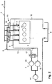
- the dual-fuel fuel injection system 2 comprises a liquid fuel injection branch 3, via which the liquid fuel is supplied to the internal combustion engine 1, and a gas fuel injection branch 4 for supplying fuel gas to the internal combustion engine 1.
- a liquid fuel line 6 in which a pump arrangement 7 is arranged, is connected to a liquid fuel tank 8. Via the pump arrangement 7, the liquid fuel from the tank 8 is fed to the liquid fuel injectors 5 under high pressure for injection into the cylinders of the internal combustion engine 1.
- the gas fuel injection branch 4 comprises a gas line 9 for supplying gas from a gas reservoir and a gas injector arrangement 10 for controlled injection of the fuel gas into the cylinders of the internal combustion engine.
- the gas injector arrangement 10 comprises control valves 11 and gas injectors 12, each associated with a control valve 11, with a gas needle, via which the fuel gas is fed into the cylinders of the internal combustion engine.
- the assigned gas injectors 12 are adjusted between the open and closed positions via the control valves 11.
- the control valves 11 of the gas injector arrangement 10 are controlled by a control fluid, which is the liquid fuel from the tank 8.
- the control valves 11 are connected via a line 13 to the pump arrangement 7 and the liquid fuel tank 8.
- the controlled injection of fuel gas into the internal combustion engine 1 takes place.
- the pump arrangement 7 comprises a backing pump 14 and two high pressure pumps 15 and 16 connected in parallel, which are connected in series with the backing pump 14 and are arranged downstream of it. Furthermore, a switching valve 17 downstream of the first high-pressure pump 15 is part of the pump arrangement 7.
- the first high-pressure pump 15 can be connected in flow connection with the liquid fuel line 6 ( Fig. 1 , Liquid fuel operation) or in flow connection with the line 13 for controlling the control valves 11 ( Fig. 2 , Gas operation).
- the second high-pressure pump 16 is located in the liquid fuel line 6, via which liquid fuel is delivered to the fuel injectors 5 both in liquid fuel operation and in gas operation.
- Both the control valves 11 of the gas injector arrangement 10 and the liquid fuel injectors 5 are connected to a leakage return line 18, via which the leakage fluid of the liquid fuel is returned to the tank 8.
- the switching valve 17 is switched in such a way that the liquid fuel delivered by the first high-pressure pump 15 is conveyed from the tank 8 exclusively into the liquid fuel line 6 of the liquid fuel injection branch 3 and further to the liquid fuel injectors 5.
- the gas fuel injection branch 4 is out of operation.
- liquid fuel is also conveyed into the line 6 and to the injectors 5 via the second high-pressure pump 16.
- the two high-pressure pumps 15 and 16 are dimensioned differently in terms of their pump output.
- the first high-pressure pump 15 has a greater pump output than the second high-pressure pump 16.
- the simultaneous operation of the two high-pressure pumps 15 and 16 makes it possible, in particular, to set the maximum pressure of the liquid fuel of, for example, 2,200 bar.
- a lower pressure of the liquid fuel can be set, for example a maximum of 1,500 bar.
- the gas operation of the dual fuel fuel injection system is in Fig. 2 shown.
- the switching valve 17 is switched in such a way that the fuel delivered by the first high-pressure pump 15 is led into the line 13 to the gas injector arrangement 10 and switches the control valves 11 there, so that gas from the gas line 9 via the control valves 11 to the Gas injectors 12 is guided, via which the injection into the cylinders of the internal combustion engine 1 takes place.
- Leakage quantities that occur in gas operation when the control valves 11 are actuated and in liquid fuel operation at the injectors 5 are returned to the fuel tank 8 via the leakage return line 18.
Landscapes
- Engineering & Computer Science (AREA)
- Chemical & Material Sciences (AREA)
- Combustion & Propulsion (AREA)
- Mechanical Engineering (AREA)
- General Engineering & Computer Science (AREA)
- Oil, Petroleum & Natural Gas (AREA)
- Chemical Kinetics & Catalysis (AREA)
- General Chemical & Material Sciences (AREA)
- Output Control And Ontrol Of Special Type Engine (AREA)
- Fuel-Injection Apparatus (AREA)
Description
- Die Erfindung bezieht sich auf ein Dual-Fuel-Kraftstoffeinspritzsystem für eine Brennkraftmaschine nach dem Oberbegriff des Anspruches 1.
- In der
DE 10 2010 061 183 A1 wird eine Brennkraftmaschine mit einem Dual-Fuel-Kraftstoffeinspritzsystem beschrieben. Der Betrieb der Brennkraftmaschine erfolgt mit flüssigem oder mit gasförmigem Kraftstoff, dessen Einspritzung über Kraftstoffinjektoren des Dual-Fuel-Kraftstoffeinspritzsystems erfolgt, wobei für die Einspritzung des Flüssigkraftstoffs im Flüssigkraftstoffbetrieb größere Injektoren und für eine Piloteinspritzung des Flüssigkraftstoffs im Gasbetrieb kleinere Injektoren vorgesehen sind. Die Förderung des Flüssigkraftstoffes zu den verschieden großen Injektoren erfolgt über entsprechend unterschiedlich dimensionierte Pumpen. - Auch aus der
DE 10 2014 105 439 A1 ist ein Dual-Fuel-Kraftstoffeinspritzsystem für Brennkraftmaschinen bekannt. Die Einspritzung erfolgt über Flüssigkraftstoffinjektoren und Brenngasinjektoren, wobei der Zufluss des Kraftstoffes zu den jeweiligen Injektoren über Schaltventile steuerbar ist. Ein weiteres Beispiel eines Dual-Fuel-Kraftstoffeinspritzsystem ist in derDE 10 2013 017 853 gezeigt. - Der Erfindung liegt die Aufgabe zugrunde, ein konstruktiv einfach aufgebautes Dual-Fuel-Kraftstoffeinspritzsystem zu schaffen.
- Diese Aufgabe wird erfindungsgemäß mit den Merkmalen des Anspruches 1 gelöst. Die Unteransprüche geben zweckmäßige Weiterbildungen an.
- Das erfindungsgemäße Dual-Fuel-Kraftstoffeinspritzsystem wird in bzw. für Brennkraftmaschinen eingesetzt und verwendet als Flüssigkraftstoff beispielsweise Dieselkraftstoff oder Schweröl oder Bioöl und als Gaskraftstoff ein Brenngas wie zum Beispiel Erdgas oder Biogas. Der Flüssigkraftstoff und der Gaskraftstoff werden über jeweils einen zugeordneten Einspritzzweig der Brennkraftmaschine zugeführt, in dem jeweils eine Injektoranordnung für die Einspritzung des flüssigen bzw. gasförmigen Kraftstoffes angeordnet ist. Die Gasinjektoranordnung im Gaskraftstoff-Einspritzzweig ist über ein Steuerfluid ansteuerbar, das die Gasinjektoranordnung zwischen Öffnungs- und Schließposition verstellt. Erfindungsgemäß bildet der Flüssigkraftstoff das Steuerfluid der Gasinjektoranordnung.
- Diese Vorgehensweise hat den Vorteil, dass kein Aktuierungskreislauf mit einem zusätzlichen Hydraulikfluid zur Ansteuerung der Gasinjektoranordnung erforderlich ist. Es genügt vielmehr, einen Teilstrom des Flüssigkraftstoffes abzuzweigen und als Steuerfluid zur Ansteuerung der Gasinjektoranordnung zu verwenden. Ein zusätzliches Hydraulikfluid für die Ansteuerung der Gasinjektoranordnung ist nicht erforderlich, so dass auch entsprechende Vorratsbehälter und Leitungen entfallen können.
- Bei der erfindungsgemäßen Ausführung genügt ein gemeinsamer Tank zur Aufnahme des Flüssigkraftstoffes, der im Flüssigkraftstoffbetrieb zu den zugeordneten Flüssigkraftstoffinjektoren geführt wird und im Gasbetrieb die Gasinjektoranordnung steuert.
- Vorteilhafterweise wird im Gasbetrieb eine Piloteinspritzung mit dem Flüssigkraftstoff zur Zündung des Gasgemisches durchgeführt.
- Gemäß einer vorteilhaften Ausführung umfasst das Dual-Fuel-Kraftstoffeinspritzsystem eine Hochdruckpumpe, über die der Flüssigkraftstoff zur Gasinjektoranordnung im Gasbetrieb gefördert wird. Die Hochdruckpumpe kann Teil einer Pumpenanordnung sein, welche mehrere parallel und/oder in Reihe geschaltete Pumpen umfasst, über die sowohl der erforderliche Druck im Flüssigkraftstoff für die Einspritzung im Flüssigkraftstoffbetrieb als auch für die Ansteuerung der Gasinjektoranordnung sowie gegebenenfalls für die Piloteinspritzung im Gasbetrieb erzeugt wird.
- Die Pumpenanordnung weist beispielsweise zwei parallel geschaltete Hochdruckpumpen auf, von denen eine erste Hochdruckpumpe zur Förderung des Flüssigkraftstoffs zur Gasinjektoranordnung zur Steuerung derselben und die zweite Hochdruckpumpe ausschließlich zur Förderung des Flüssigkraftstoffs zu Flüssigkraftstoffinjektoren eingesetzt werden. Die erste Hochdruckpumpe kann gegebenenfalls zusätzlich im Flüssigkraftstoffbetrieb zu den Flüssigkraftstoffinjektoren fördern, so dass diesen Injektoren der Flüssigkraftstoff gemeinsam mit der zweiten Hochdruckpumpe zugeführt wird. Diese Ausführung hat den Vorteil, dass beide Hochdruckpumpen kleiner dimensioniert werden können als eine einzige Pumpe, welche den hohen Flüssigkraftstoffdruck für den Flüssigkraftstoffbetrieb zur Verfügung stellen muss.
- Indem zwei Pumpen vorgesehen sind, können diese, gemäß einer weiteren vorteilhaften Ausführung, im Hinblick auf ihre Pumpenleistung unterschiedlich groß dimensioniert sein. Hierbei ist insbesondere diejenige Hochdruckpumpe, die zur Ansteuerung der Gasinjektoranordnung verwendet wird, größer dimensioniert als die weitere Hochdruckpumpe, die ausschließlich zur Förderung des Flüssigkraftstoffs zu den Flüssigkraftstoffinjektoren eingesetzt wird. Es kann beispielsweise zweckmäßig sein, dass die größere Hochdruckpumpe mindestens 75 %, gegebenenfalls mindestens 90 % der Gesamtpumpenleistung und die zweite Hochdruckpumpe entsprechend nur maximal 25 % oder maximal 10 % der Gesamtpumpenleistung erbringt.
- In einer weiteren Ausführung ist die Hochdruckpumpe, die zur Ansteuerung der Gasinjektoranordnung verwendet wird, kleiner dimensioniert als die weitere Hochdruckpumpe, die ausschließlich zur Förderung des Flüssigkraftstoffs zu den Flüssigkraftstoffinjektoren eingesetzt wird.
- Es kann zweckmäßig sein, der einen oder den mehreren Hochdruckpumpen, insbesondere in der Ausführung mit zwei parallel geschalteten Hochdruckpumpen, eine Vorförderpumpe vorzuschalten. Des Weiteren ist es auch möglich, lediglich eine Hochdruckpumpe vorzusehen, die ausreichend groß dimensioniert ist, um insbesondere den hohen Druck im Flüssigkraftstoffbetrieb zu erzeugen.
- Für den Fall mehrerer Hochdruckpumpen, insbesondere zwei parallel geschaltete Hochdruckpumpen können diese in einem gemeinsamen Pumpengehäuse angeordnet sein, wobei gegebenenfalls die Ausgänge der Pumpen separat geregelt werden, beispielsweise über jeweils eine Saugdrosselregelung. Der Vorteil des gemeinsamen Pumpengehäuses für mehrere Pumpen liegt im geringeren Bauraumbedarf.
- Gemäß noch einer weiteren zweckmäßigen Ausführung ist der Hochdruckpumpe, über die wahlweise Flüssigkraftstoff zu den Flüssigkraftstoffinjektoren oder zur Gasinjektoranordnung förderbar ist, eine Schalteinrichtung zugeordnet, die zwischen verschiedenen Schaltpositionen verstellbar ist. Je nach Schaltposition der Schalteinrichtung wird Flüssigkraftstoff zu den Flüssigkraftstoffinjektoren oder zur Gasinjektoranordnung gefördert.
- Die Schalteinrichtung kann entweder in die Hochdruckpumpe integriert oder separat von der Hochdruckpumpe ausgebildet sowie außerhalb der Hochdruckpumpe angeordnet sein. Bei in die Hochdruckpumpe integrierter Schalteinrichtung weist die Hochdruckpumpe beispielsweise zwei Ausgänge auf, die jeweils geöffnet und geschlossen werden können und die ein wahlweises Fördern von Flüssigkraftstoff zu den Flüssigkraftstoffinjektoren oder zur Gasinjektoranordnung ermöglichen.
- Gemäß noch einer weiteren zweckmäßigen Ausführung ist der Hochdruckpumpe, über die wahlweise Flüssigkraftstoff zu den Flüssigkraftstoffinjektoren oder zur Gasinjektoranordnung förderbar ist, ein die Schalteinrichtung bildendes Schaltventil nachgeordnet, um je nach Betriebsart Flüssigkraftstoff entweder nur zu den Flüssigkraftstoffinjektoren für den Flüssigkraftstoffbetrieb oder Flüssigkraftstoff im Gasbetrieb sowohl zur Steuerung der Gasinjektoranordnung als auch zur Piloteinspritzung zu den Kraftstoffinjektoren zu fördern. In dieser Ausführung ist die Schalteinrichtung separat von der Hochdruckpumpe ausgebildet.
- Gemäß einer weiteren zweckmäßigen Ausführung ist die Gasinjektoranordnung über eine Leckagerücklaufleitung mit einem Flüssigkraftstofftank verbunden. Ebenso können die Flüssigkraftstoffinjektoren über eine Leckagerücklaufleitung mit dem Flüssigkraftstofftank verbunden sein. Vorteilhafterweise münden Leitungsabschnitte von der Gasinjektoranordnung und den Flüssigkraftinjektoren in eine gemeinsame Leckagerücklaufleitung.
- Die Hochdruckpumpe bzw. die Hochdruckpumpen können gegebenenfalls über Elektromotoren angetrieben werden, wodurch der Energiebedarf minimiert werden kann und außerdem eine präzise Steuerung der Pumpen möglich ist.
- Gemäß einer weiteren vorteilhaften Ausführung befindet sich in der Steuerfluidleitung, die von der Pumpenanordnung zur Gasinjektoranordnung führt, ein Überdruckventil zum Schutz der Gasinjektoranordnung vor einem zu hohen Druck, insbesondere während eines Umschaltvorgangs zwischen Gas- und Flüssigkraftstoffbetrieb. Das Überdruckventil kann über eine Verbindungsleitung mit dem Flüssigkraftstofftank oder der Leckageleitung verbunden sein.
- Weitere Vorteile und zweckmäßige Ausführungen sind den weiteren Ansprüchen, der Figurenbeschreibung und den Zeichnungen zu entnehmen. Es zeigen:
- Fig. 1
- in schematischer Darstellung eine Brennkraftmaschine mit einem Dual-Fuel-Kraftstoffeinspritzsystem, dargestellt im Flüssigkraftstoffbetrieb,
- Fig. 2
- die Brennkraftmaschine mit Dual-Fuel-Kraftstoffeinspritzsystem, dargestellt im Gasbetrieb.
- In den Figuren sind gleiche Bauteile mit gleichen Bezugszeichen versehen.
- In den
Fig. 1 und2 ist eine Brennkraftmaschine 1 dargestellt, die mit einem Dual-Fuel-Kraftstoffeinspritzsystem 2 für den alternativen Betrieb mit Flüssigkraftstoff und mit Brenngas ausgestattet ist. Das Dual-Fuel-Kraftstoffeinspritzsystem 2 umfasst einen Flüssigkraftstoff-Einspritzzweig 3, über den der Flüssigkraftstoff der Brennkraftmaschine 1 zugeführt wird, sowie einen Gaskraftstoff-Einspritzzweig 4 zur Zufuhr von Brenngas zur Brennkraftmaschine 1. Im Flüssigkeitskraftstoff-Einspritzzweig 3 befinden sich Kraftstoffinjektoren 5, die über eine Flüssigkraftstoffleitung 6, in der eine Pumpenanordnung 7 angeordnet ist, mit einem Flüssigkeitskraftstofftank 8 verbunden sind. Über die Pumpenanordnung 7 wird der Flüssigkraftstoff aus dem Tank 8 unter Hochdruck den Flüssigkeitskraftstoffinjektoren 5 zur Einspritzung in die Zylinder der Brennkraftmaschine 1 zugeführt. - Der Gaskraftstoff-Einspritzzweig 4 umfasst eine Gasleitung 9 zur Zufuhr von Gas aus einem Gasreservoir und eine Gasinjektoranordnung 10 zur gesteuerten Einspritzung des Brenngases in die Zylinder der Brennkraftmaschine. Die Gasinjektoranordnung 10 umfasst Steuerventile 11 sowie jeweils einem Steuerventil 11 zugeordnete Gasinjektoren 12 mit einer Gasnadel, über die das Brenngas in die Zylinder der Brennkraftmaschine geleitet wird. Über die Steuerventile 11 werden die zugeordneten Gasinjektoren 12 zwischen Öffnungs- und Schließposition verstellt.
- Die Steuerventile 11 der Gasinjektoranordnung 10 werden von einem Steuerfluid gesteuert, bei dem es sich um den Flüssigkraftstoff aus dem Tank 8 handelt. Die Steuerventile 11 sind über eine Leitung 13 mit der Pumpenanordnung 7 und dem Flüssigkraftstofftank 8 verbunden. Über die Ansteuerung der Steuerventile 11 im Gasbetrieb mithilfe des Flüssigkraftstoffes, der als Steuerfluid fungiert, erfolgt die gesteuerte Einspritzung von Brenngas in die Brennkraftmaschine 1.
- Die Pumpenanordnung 7 umfasst eine Vorpumpe 14 und zwei parallel geschaltete Hochdruckpumpen 15 und 16, die mit der Vorpumpe 14 in Reihe geschaltet und dieser nachgeordnet sind. Des Weiteren gehört ein Schaltventil 17 stromab der ersten Hochdruckpumpe 15 zur Pumpenanordnung 7. Die erste Hochdruckpumpe 15 kann mithilfe des Schaltventils 17 in Strömungsverbindung mit der Flüssigkeitskraftstoffleitung 6 (
Fig. 1 , Flüssigkraftstoffbetrieb) oder in Strömungsverbindung mit der Leitung 13 zur Ansteuerung der Steuerventile 11 (Fig. 2 , Gasbetrieb) geschaltet werden. Die zweite Hochdruckpumpe 16 befindet sich in der Flüssigkeitskraftstoffleitung 6, über die sowohl im Flüssigkraftstoffbetrieb als auch im Gasbetrieb Flüssigkraftstoff zu den Kraftstoffinjektoren 5 gefördert wird. - Sowohl die Steuerventile 11 der Gasinjektoranordnung 10 als auch die FlüssigKraftstoffinjektoren 5 sind mit einer Leckagerücklaufleitung 18 verbunden, über die Leckagefluid des Flüssigkraftstoffes zum Tank 8 zurückgeführt wird.
- Bei dem in
Fig. 1 dargestellten Flüssigkraftstoffbetrieb ist das Schaltventil 17 in der Weise geschaltet, dass der von der ersten Hochdruckpumpe 15 geförderte Flüssigkraftstoff aus dem Tank 8 ausschließlich in die Flüssigkraftstoffleitung 6 des Flüssigkraftstoff-Einspritzzweigs 3 und weiter zu den Flüssigkraftstoffinjektoren 5 gefördert wird. Der Gaskraftstoff-Einspritzzweig 4 ist außer Betrieb. - Zusätzlich zur ersten Hochdruckpumpe 15 wird auch über die zweite Hochdruckpumpe 16 Flüssigkraftstoff in die Leitung 6 und zu den Injektoren 5 gefördert. Die beiden Hochdruckpumpen 15 und 16 sind im Hinblick auf ihre Pumpenleistung unterschiedlich groß dimensioniert. Die erste Hochdruckpumpe 15 weist eine größere Pumpenleistung als die zweite Hochdruckpumpe 16 auf. Über den gleichzeitigen Betrieb der beiden Hochdruckpumpen 15 und 16 ist insbesondere der maximale Druck des Flüssigkraftstoffs von beispielsweise 2.200 bar einstellbar. Über den alleinigen Betrieb der zweiten Hochdruckpumpe 16 ist dagegen nur ein geringerer Druck des Flüssigkeitskraftstoffes einstellbar, beispielsweise maximal 1.500 bar.
- Es kann gegebenenfalls genügen, dass im Flüssigkraftstoffbetrieb gemäß
Fig. 1 nur die erste Hochdruckpumpe 15 in Betrieb ist. - Der Gasbetrieb des Dual-Fuel-Kraftstoffeinspritzsystems ist in
Fig. 2 dargestellt. Im Gasbetrieb ist das Schaltventil 17 in der Weise geschaltet, dass der von der ersten Hochdruckpumpe 15 geförderte Kraftstoff in die Leitung 13 zu der Gasinjektoranordnung 10 geführt wird und dort die Steuerventile 11 schaltet, so dass Gas aus der Gasleitung 9 über die Steuerventile 11 zu den Gasinjektoren 12 geführt wird, über die die Einspritzung in die Zylinder der Brennkraftmaschine 1 erfolgt. - Zugleich wird über die zweite Hochdruckpumpe 16 Kraftstoff in die Flüssigkraftstoffleitung 6 und weiter zu den Flüssigkraftstoffinjektoren 5 geleitet, um eine Piloteinspritzung für die Zündung des Gasgemisches durchzuführen. Der Druck, unter dem der Flüssigkraftstoff von der zweiten Hochdruckpumpe 16 gefördert wird, liegt niedriger als der Druck des Flüssigkraftstoffes im Flüssigkraftstoffbetrieb gemäß
Fig. 1 . - Leckagemengen, die im Gasbetrieb bei der Ansteuerung der Steuerventile 11 und im Flüssigkraftstoffbetrieb an den Injektoren 5 auftreten, werden über die Leckagerücklaufleitung 18 zum Kraftstofftank 8 zurückgeführt.
Claims (11)
- Dual-Fuel-Kraftstoffeinspritzsystem für eine Brennkraftmaschine, mit einem Flüssigkraftstoff-Einspritzzweig (3) und einem Gaskraftstoff-Einspritzzweig (4) und mit einer Gasinjektoranordnung (10) im Gaskraftstoff-Einspritzzweig (4), die über ein Steuerfluid ansteuerbar ist, und wobei der Flüssigkraftstoff das Steuerfluid der Gasinjektoranordnung (10) bildet,
dadurch gekennzeichnet, dass eine erste Hochdruckpumpe (15) mit einer Schalteinrichtung (17) zur wahlweisen Förderung des Flüssigkraftstoffs zu den Flüssigkraftstoffinjektoren (5) oder zur Gasinjektoranordnung (10) angeordnet ist, dass das Dual-Fuel-Kraftstoffeinspritzsystem (2) die Hochdruckpumpe (15) zur Förderung des Flüssigkraftstoffs zur Gasinjektoranordnung (10) im Gasbetrieb umfasst, und dass das Dual-Fuel-Kraftstoffeinspritzsystem (2) eine zweite Hochdruckpumpe (16) zur Förderung des Flüssigkraftstoffs zu Flüssigkraftstoffinjektoren (5) im Flüssigkraftstoff-Einspritzzweig (3) umfasst. - Dual-Fuel-Kraftstoffeinspritzsystem nach Anspruch 1, dadurch gekennzeichnet, dass die Schalteinrichtung (17) als ein der gemeinsamen Hochdruckpumpe (15) nachgeordnetes Schaltventil (17) ausgebildet ist.
- Dual-Fuel-Kraftstoffeinspritzsystem nach einem der Ansprüche 1 bis 2, dadurch gekennzeichnet, dass mindestens zwei Hochdruckpumpen (15, 16) angeordnet sind, von denen die erste Hochdruckpumpe (15) zur Förderung des Flüssigkraftstoffs zur Gasinjektoranordnung (10) und die zweite Hochdruckpumpe (16) ausschließlich zur Förderung des Flüssigkraftstoffs zu Flüssigkraftstoffinjektoren (5) einsetzbar ist.
- Dual-Fuel-Kraftstoffeinspritzsystem nach Anspruch 3,
dadurch gekennzeichnet, dass den Hochdruckpumpen (15, 16) eine Vorförderpumpe (14) vorgeschaltet ist. - Dual-Fuel-Kraftstoffeinspritzsystem nach Anspruch 3 oder 4, dadurch gekennzeichnet, dass die Hochdruckpumpen (15, 16) parallel geschaltet sind.
- Dual-Fuel-Kraftstoffeinspritzsystem nach einem der Ansprüche 3 bis 5, dadurch gekennzeichnet, dass über die erste Hochdruckpumpe (15) wahlweise Flüssigkraftstoff zu den Flüssigkraftstoffinjektoren (5) oder zur Gasinjektoranordnung (10) förderbar ist.
- Dual-Fuel-Kraftstoffeinspritzsystem nach einem der Ansprüche 3 bis 6, dadurch gekennzeichnet, dass die Hochdruckpumpen (15, 16) eine unterschiedlich große Pumpenleistung aufweisen.
- Dual-Fuel-Kraftstoffeinspritzsystem nach einem der Ansprüche 1 bis 7, dadurch gekennzeichnet, dass die Gasinjektoranordnung (10) über eine Leckagerücklaufleitung (18) mit einem Flüssigkraftstofftank verbunden ist.
- Dual-Fuel-Kraftstoffeinspritzsystem nach einem der Ansprüche 1 bis 8, dadurch gekennzeichnet, dass die Flüssigkraftstoffinjektoren (5) über eine Leckagerücklaufleitung (18) mit dem Flüssigkraftstofftank verbunden sind.
- Brennkraftmaschine mit einem Dual-Fuel-Kraftstoffeinspritzsystem (2) nach einem der Ansprüche 1 bis 9.
- Verfahren zum Betrieb eines Dual-Fuel-Kraftstoffeinspritzsystem (2) nach einem der Ansprüche 1 bis 10, bei dem im Gasbetrieb Flüssigkraftstoff als Steuerfluid zur Gasinjektoranordnung (10) und zusätzlich Flüssigkraftstoff zu den Flüssigkraftstoffinjektoren (5) gefördert wird.
Applications Claiming Priority (2)
| Application Number | Priority Date | Filing Date | Title |
|---|---|---|---|
| DE102016107454.3A DE102016107454B4 (de) | 2016-04-22 | 2016-04-22 | Dual-Fuel-Kraftstoffeinspritzsystem für eine Brennkraftmaschine |
| PCT/EP2017/025093 WO2017182142A1 (de) | 2016-04-22 | 2017-04-21 | Dual-fuel-kraftstoffeinspritzsystem für eine brennkraftmaschine |
Publications (2)
| Publication Number | Publication Date |
|---|---|
| EP3445963A1 EP3445963A1 (de) | 2019-02-27 |
| EP3445963B1 true EP3445963B1 (de) | 2020-06-24 |
Family
ID=58672557
Family Applications (1)
| Application Number | Title | Priority Date | Filing Date |
|---|---|---|---|
| EP17721961.5A Active EP3445963B1 (de) | 2016-04-22 | 2017-04-21 | Dual-fuel-kraftstoffeinspritzsystem für eine brennkraftmaschine |
Country Status (5)
| Country | Link |
|---|---|
| US (1) | US10989122B2 (de) |
| EP (1) | EP3445963B1 (de) |
| CN (1) | CN108779740A (de) |
| DE (1) | DE102016107454B4 (de) |
| WO (1) | WO2017182142A1 (de) |
Families Citing this family (5)
| Publication number | Priority date | Publication date | Assignee | Title |
|---|---|---|---|---|
| DK3520510T3 (da) * | 2016-09-30 | 2022-06-07 | Ericsson Telefon Ab L M | Autonom tidsjustering til en trådløs indretning |
| DE102019209232A1 (de) * | 2019-06-26 | 2020-12-31 | Technische Universität München | HPDF-Betriebsverfahren für eine Brennkraftmaschine, Brennkraftmaschine und Arbeitsvorrichtung |
| CH716420A1 (de) * | 2019-07-18 | 2021-01-29 | Liebherr Machines Bulle Sa | Verfahren zur Konditionierung eines flüssigen Brenngases zur Hochdruckeinspritzung in eine Verbrennungskraftmaschine. |
| US11111848B1 (en) * | 2020-06-02 | 2021-09-07 | Pratt & Whitney Canada Corp. | Fuel injection system for aircraft engine |
| FR3132124B1 (fr) * | 2022-01-25 | 2026-05-01 | Renault Sas | Système d’alimentation à haute pression pour l’injection directe de carburant liquide dans un moteur à combustion interne à bicarburation |
Family Cites Families (13)
| Publication number | Priority date | Publication date | Assignee | Title |
|---|---|---|---|---|
| JP2538908B2 (ja) * | 1987-03-15 | 1996-10-02 | 三菱重工業株式会社 | 2種燃料エンジンの噴射システム |
| GB9121592D0 (en) * | 1991-10-11 | 1991-11-27 | Ricardo Consulting Eng | Fuel injectors for diesel engines |
| CA2204983A1 (en) * | 1997-05-09 | 1998-11-09 | Westport Research Inc. | Hydraulically actuated gaseous or dual fuel injector |
| US5890459A (en) * | 1997-09-12 | 1999-04-06 | Southwest Research Institute | System and method for a dual fuel, direct injection combustion engine |
| JP4297181B2 (ja) | 2007-07-17 | 2009-07-15 | 株式会社デンソー | インジェクタ |
| US8333171B2 (en) * | 2009-02-06 | 2012-12-18 | Exen Holdings, Llc | Homogenizing fuel enhancement system |
| US20120186560A1 (en) * | 2009-02-06 | 2012-07-26 | Exen Holdings, Llc | Homogenizing fuel enhancement system |
| WO2011130791A1 (en) * | 2010-04-20 | 2011-10-27 | Dgc Industries Pty Ltd | A dual fuel supply system for a direct-injection system of a diesel engine with on-board mixing |
| DE102010061183B4 (de) | 2010-12-13 | 2014-10-30 | L'orange Gmbh | Mit flüssigem und/oder gasförmigem Kraftstoff zu betreibende Brennkraftmaschine |
| US9376992B2 (en) * | 2012-06-04 | 2016-06-28 | Caterpillar Inc. | Dual fuel injector and fuel system |
| US9279391B2 (en) * | 2013-04-23 | 2016-03-08 | Caterpillar Inc. | Dual fuel system and engine system operating method |
| DE102013017853B4 (de) * | 2013-10-26 | 2021-03-04 | Woodward L'orange Gmbh | Verfahren zur Ausführung mit einem Dual-Fuel-Kraftstoffeinspritzsystem |
| DE102014105439B4 (de) | 2014-04-16 | 2020-03-26 | Woodward L'orange Gmbh | Mengenbegrenzungsventil für ein Dual-Fuel-Kraftstoffeinspritzsystem |
-
2016
- 2016-04-22 DE DE102016107454.3A patent/DE102016107454B4/de active Active
-
2017
- 2017-04-21 CN CN201780015510.8A patent/CN108779740A/zh active Pending
- 2017-04-21 EP EP17721961.5A patent/EP3445963B1/de active Active
- 2017-04-21 US US16/094,812 patent/US10989122B2/en active Active
- 2017-04-21 WO PCT/EP2017/025093 patent/WO2017182142A1/de not_active Ceased
Non-Patent Citations (1)
| Title |
|---|
| None * |
Also Published As
| Publication number | Publication date |
|---|---|
| CN108779740A (zh) | 2018-11-09 |
| DE102016107454B4 (de) | 2022-02-17 |
| US10989122B2 (en) | 2021-04-27 |
| DE102016107454A1 (de) | 2017-10-26 |
| WO2017182142A1 (de) | 2017-10-26 |
| EP3445963A1 (de) | 2019-02-27 |
| US20190120149A1 (en) | 2019-04-25 |
Similar Documents
| Publication | Publication Date | Title |
|---|---|---|
| EP3060783B1 (de) | Zwei-kraftstoff-einspritzsystem und verfahren zur ausführung mit einem solchen | |
| DE102004009792B3 (de) | Kraftstoffzuführeinrichtung zur Versorgung der Injektoren an Brennräumen einer Brennkraftmaschine mit Kraftstoff | |
| EP3292289B1 (de) | Verfahren zum betreiben einer wassereinspritzvorrichtung für eine brennkraftmaschine | |
| DE10157135B4 (de) | Kraftstoffversorgungsanlage in Form eines Common-Rail-Systems einer Brennkraftmaschine mit mehreren Zylindern | |
| DE112008002451B4 (de) | System und Methode zum Dosieren von Treibstoff in einem Hochdruck-Pumpensystem | |
| DE102016107454B4 (de) | Dual-Fuel-Kraftstoffeinspritzsystem für eine Brennkraftmaschine | |
| DE102010050560A1 (de) | Kraftstoffhochdruckpumpe für eine Brennkraftmaschine mit Direkteinspritzung | |
| EP3346120B1 (de) | Wassereinspritzvorrichtung einer brennkraftmaschine und verfahren zum betreiben einer solchen wassereinspritzvorrichtung | |
| EP1209349B1 (de) | Kraftstoffeinspritzsystem mit Kraftstoffvorwärmung und kraftstoffgekühltem Druckregelventil | |
| DE10215021A1 (de) | Kraftstoffeinspritzeinrichtung für eine Brennkraftmaschine | |
| DE112012001588T5 (de) | Dieselmotor für eine LPG-Dieselmischung | |
| DE102004060003A1 (de) | Kraftstoffversorgungsanlage in Form eines Common-Rail-Systems für mehrere Zylinder einer Brennkraftmaschine | |
| EP1476656A1 (de) | Kraftstoffeinspritzeinrichtung für eine brennkraftmaschine | |
| DE102020114581A1 (de) | Überströmventilanordnung zur verbesserten mindestförderfähigkeit in einem kraftstoffsystem | |
| EP2476890B1 (de) | Versorgungsvorrichtung mit einer Kraftstoffördereinrichtung und Verwendung einer dahingehenden Versorgungsvorrichtung | |
| DE102011112947B3 (de) | Hochdruckpumpensystem | |
| DE102008049492B4 (de) | Kraftstoff-Einspritzvorfüllsystem | |
| WO2015158413A1 (de) | Mengenbegrenzungsventil, insbesondere für ein dual-fuel-kraftstoffeinspritzsystem | |
| DE102014007880B4 (de) | Verfahren zur Einstellung des Drucks in einem Hochdrucksystem eines Kraftstoffeinspritzsystems einer Brennkraftmaschine und Brennkraftmaschine zur Durchführung des Verfahrens | |
| DE10057683B4 (de) | Kraftstoffeinspritzeinrichtung | |
| DE102017204925B3 (de) | Ventilanordnung für ein Kraftstoffeinspritzsystem sowie Kraftstoffeinspritzsystem | |
| DE102015006999B4 (de) | Brenngasinjektor | |
| DE102017131242B4 (de) | Doppelinjektor, Verfahren zum Betrieb eines Doppelinjektors, Einrichtung zum Steuern und/oder Regeln eines Doppelinjektors und Brennkraftmaschine | |
| DE102009047488A1 (de) | Kraftstoffeinspritzeinrichtung für eine Brennkraftmaschine | |
| DE19812011A1 (de) | Verfahren zur Einspritzung von Kraftstoff in den Brennraum einer Brennkraftmaschine und Kraftstoffeinspritzsystem |
Legal Events
| Date | Code | Title | Description |
|---|---|---|---|
| STAA | Information on the status of an ep patent application or granted ep patent |
Free format text: STATUS: UNKNOWN |
|
| STAA | Information on the status of an ep patent application or granted ep patent |
Free format text: STATUS: THE INTERNATIONAL PUBLICATION HAS BEEN MADE |
|
| PUAI | Public reference made under article 153(3) epc to a published international application that has entered the european phase |
Free format text: ORIGINAL CODE: 0009012 |
|
| STAA | Information on the status of an ep patent application or granted ep patent |
Free format text: STATUS: REQUEST FOR EXAMINATION WAS MADE |
|
| 17P | Request for examination filed |
Effective date: 20180912 |
|
| AK | Designated contracting states |
Kind code of ref document: A1 Designated state(s): AL AT BE BG CH CY CZ DE DK EE ES FI FR GB GR HR HU IE IS IT LI LT LU LV MC MK MT NL NO PL PT RO RS SE SI SK SM TR |
|
| AX | Request for extension of the european patent |
Extension state: BA ME |
|
| DAV | Request for validation of the european patent (deleted) | ||
| DAX | Request for extension of the european patent (deleted) | ||
| GRAP | Despatch of communication of intention to grant a patent |
Free format text: ORIGINAL CODE: EPIDOSNIGR1 |
|
| STAA | Information on the status of an ep patent application or granted ep patent |
Free format text: STATUS: GRANT OF PATENT IS INTENDED |
|
| INTG | Intention to grant announced |
Effective date: 20200306 |
|
| GRAS | Grant fee paid |
Free format text: ORIGINAL CODE: EPIDOSNIGR3 |
|
| GRAA | (expected) grant |
Free format text: ORIGINAL CODE: 0009210 |
|
| STAA | Information on the status of an ep patent application or granted ep patent |
Free format text: STATUS: THE PATENT HAS BEEN GRANTED |
|
| AK | Designated contracting states |
Kind code of ref document: B1 Designated state(s): AL AT BE BG CH CY CZ DE DK EE ES FI FR GB GR HR HU IE IS IT LI LT LU LV MC MK MT NL NO PL PT RO RS SE SI SK SM TR |
|
| REG | Reference to a national code |
Ref country code: GB Ref legal event code: FG4D Free format text: NOT ENGLISH |
|
| REG | Reference to a national code |
Ref country code: CH Ref legal event code: EP |
|
| REG | Reference to a national code |
Ref country code: DE Ref legal event code: R096 Ref document number: 502017005874 Country of ref document: DE |
|
| REG | Reference to a national code |
Ref country code: AT Ref legal event code: REF Ref document number: 1284121 Country of ref document: AT Kind code of ref document: T Effective date: 20200715 |
|
| REG | Reference to a national code |
Ref country code: IE Ref legal event code: FG4D Free format text: LANGUAGE OF EP DOCUMENT: GERMAN |
|
| PG25 | Lapsed in a contracting state [announced via postgrant information from national office to epo] |
Ref country code: LT Free format text: LAPSE BECAUSE OF FAILURE TO SUBMIT A TRANSLATION OF THE DESCRIPTION OR TO PAY THE FEE WITHIN THE PRESCRIBED TIME-LIMIT Effective date: 20200624 Ref country code: SE Free format text: LAPSE BECAUSE OF FAILURE TO SUBMIT A TRANSLATION OF THE DESCRIPTION OR TO PAY THE FEE WITHIN THE PRESCRIBED TIME-LIMIT Effective date: 20200624 Ref country code: NO Free format text: LAPSE BECAUSE OF FAILURE TO SUBMIT A TRANSLATION OF THE DESCRIPTION OR TO PAY THE FEE WITHIN THE PRESCRIBED TIME-LIMIT Effective date: 20200924 Ref country code: GR Free format text: LAPSE BECAUSE OF FAILURE TO SUBMIT A TRANSLATION OF THE DESCRIPTION OR TO PAY THE FEE WITHIN THE PRESCRIBED TIME-LIMIT Effective date: 20200925 Ref country code: FI Free format text: LAPSE BECAUSE OF FAILURE TO SUBMIT A TRANSLATION OF THE DESCRIPTION OR TO PAY THE FEE WITHIN THE PRESCRIBED TIME-LIMIT Effective date: 20200624 |
|
| REG | Reference to a national code |
Ref country code: LT Ref legal event code: MG4D |
|
| PG25 | Lapsed in a contracting state [announced via postgrant information from national office to epo] |
Ref country code: LV Free format text: LAPSE BECAUSE OF FAILURE TO SUBMIT A TRANSLATION OF THE DESCRIPTION OR TO PAY THE FEE WITHIN THE PRESCRIBED TIME-LIMIT Effective date: 20200624 Ref country code: RS Free format text: LAPSE BECAUSE OF FAILURE TO SUBMIT A TRANSLATION OF THE DESCRIPTION OR TO PAY THE FEE WITHIN THE PRESCRIBED TIME-LIMIT Effective date: 20200624 Ref country code: HR Free format text: LAPSE BECAUSE OF FAILURE TO SUBMIT A TRANSLATION OF THE DESCRIPTION OR TO PAY THE FEE WITHIN THE PRESCRIBED TIME-LIMIT Effective date: 20200624 Ref country code: BG Free format text: LAPSE BECAUSE OF FAILURE TO SUBMIT A TRANSLATION OF THE DESCRIPTION OR TO PAY THE FEE WITHIN THE PRESCRIBED TIME-LIMIT Effective date: 20200924 |
|
| REG | Reference to a national code |
Ref country code: NL Ref legal event code: MP Effective date: 20200624 |
|
| PG25 | Lapsed in a contracting state [announced via postgrant information from national office to epo] |
Ref country code: AL Free format text: LAPSE BECAUSE OF FAILURE TO SUBMIT A TRANSLATION OF THE DESCRIPTION OR TO PAY THE FEE WITHIN THE PRESCRIBED TIME-LIMIT Effective date: 20200624 Ref country code: NL Free format text: LAPSE BECAUSE OF FAILURE TO SUBMIT A TRANSLATION OF THE DESCRIPTION OR TO PAY THE FEE WITHIN THE PRESCRIBED TIME-LIMIT Effective date: 20200624 |
|
| PG25 | Lapsed in a contracting state [announced via postgrant information from national office to epo] |
Ref country code: RO Free format text: LAPSE BECAUSE OF FAILURE TO SUBMIT A TRANSLATION OF THE DESCRIPTION OR TO PAY THE FEE WITHIN THE PRESCRIBED TIME-LIMIT Effective date: 20200624 Ref country code: CZ Free format text: LAPSE BECAUSE OF FAILURE TO SUBMIT A TRANSLATION OF THE DESCRIPTION OR TO PAY THE FEE WITHIN THE PRESCRIBED TIME-LIMIT Effective date: 20200624 Ref country code: ES Free format text: LAPSE BECAUSE OF FAILURE TO SUBMIT A TRANSLATION OF THE DESCRIPTION OR TO PAY THE FEE WITHIN THE PRESCRIBED TIME-LIMIT Effective date: 20200624 Ref country code: PT Free format text: LAPSE BECAUSE OF FAILURE TO SUBMIT A TRANSLATION OF THE DESCRIPTION OR TO PAY THE FEE WITHIN THE PRESCRIBED TIME-LIMIT Effective date: 20201026 Ref country code: IT Free format text: LAPSE BECAUSE OF FAILURE TO SUBMIT A TRANSLATION OF THE DESCRIPTION OR TO PAY THE FEE WITHIN THE PRESCRIBED TIME-LIMIT Effective date: 20200624 Ref country code: SM Free format text: LAPSE BECAUSE OF FAILURE TO SUBMIT A TRANSLATION OF THE DESCRIPTION OR TO PAY THE FEE WITHIN THE PRESCRIBED TIME-LIMIT Effective date: 20200624 Ref country code: EE Free format text: LAPSE BECAUSE OF FAILURE TO SUBMIT A TRANSLATION OF THE DESCRIPTION OR TO PAY THE FEE WITHIN THE PRESCRIBED TIME-LIMIT Effective date: 20200624 |
|
| PG25 | Lapsed in a contracting state [announced via postgrant information from national office to epo] |
Ref country code: PL Free format text: LAPSE BECAUSE OF FAILURE TO SUBMIT A TRANSLATION OF THE DESCRIPTION OR TO PAY THE FEE WITHIN THE PRESCRIBED TIME-LIMIT Effective date: 20200624 Ref country code: SK Free format text: LAPSE BECAUSE OF FAILURE TO SUBMIT A TRANSLATION OF THE DESCRIPTION OR TO PAY THE FEE WITHIN THE PRESCRIBED TIME-LIMIT Effective date: 20200624 Ref country code: IS Free format text: LAPSE BECAUSE OF FAILURE TO SUBMIT A TRANSLATION OF THE DESCRIPTION OR TO PAY THE FEE WITHIN THE PRESCRIBED TIME-LIMIT Effective date: 20201024 |
|
| REG | Reference to a national code |
Ref country code: DE Ref legal event code: R097 Ref document number: 502017005874 Country of ref document: DE |
|
| PG25 | Lapsed in a contracting state [announced via postgrant information from national office to epo] |
Ref country code: DK Free format text: LAPSE BECAUSE OF FAILURE TO SUBMIT A TRANSLATION OF THE DESCRIPTION OR TO PAY THE FEE WITHIN THE PRESCRIBED TIME-LIMIT Effective date: 20200624 |
|
| PLBE | No opposition filed within time limit |
Free format text: ORIGINAL CODE: 0009261 |
|
| STAA | Information on the status of an ep patent application or granted ep patent |
Free format text: STATUS: NO OPPOSITION FILED WITHIN TIME LIMIT |
|
| 26N | No opposition filed |
Effective date: 20210325 |
|
| PG25 | Lapsed in a contracting state [announced via postgrant information from national office to epo] |
Ref country code: SI Free format text: LAPSE BECAUSE OF FAILURE TO SUBMIT A TRANSLATION OF THE DESCRIPTION OR TO PAY THE FEE WITHIN THE PRESCRIBED TIME-LIMIT Effective date: 20200624 |
|
| PG25 | Lapsed in a contracting state [announced via postgrant information from national office to epo] |
Ref country code: MC Free format text: LAPSE BECAUSE OF FAILURE TO SUBMIT A TRANSLATION OF THE DESCRIPTION OR TO PAY THE FEE WITHIN THE PRESCRIBED TIME-LIMIT Effective date: 20200624 |
|
| GBPC | Gb: european patent ceased through non-payment of renewal fee |
Effective date: 20210421 |
|
| PG25 | Lapsed in a contracting state [announced via postgrant information from national office to epo] |
Ref country code: LU Free format text: LAPSE BECAUSE OF NON-PAYMENT OF DUE FEES Effective date: 20210421 |
|
| REG | Reference to a national code |
Ref country code: BE Ref legal event code: MM Effective date: 20210430 |
|
| PG25 | Lapsed in a contracting state [announced via postgrant information from national office to epo] |
Ref country code: GB Free format text: LAPSE BECAUSE OF NON-PAYMENT OF DUE FEES Effective date: 20210421 Ref country code: FR Free format text: LAPSE BECAUSE OF NON-PAYMENT OF DUE FEES Effective date: 20210430 |
|
| PG25 | Lapsed in a contracting state [announced via postgrant information from national office to epo] |
Ref country code: IE Free format text: LAPSE BECAUSE OF NON-PAYMENT OF DUE FEES Effective date: 20210421 |
|
| PG25 | Lapsed in a contracting state [announced via postgrant information from national office to epo] |
Ref country code: IS Free format text: LAPSE BECAUSE OF FAILURE TO SUBMIT A TRANSLATION OF THE DESCRIPTION OR TO PAY THE FEE WITHIN THE PRESCRIBED TIME-LIMIT Effective date: 20201024 |
|
| PG25 | Lapsed in a contracting state [announced via postgrant information from national office to epo] |
Ref country code: BE Free format text: LAPSE BECAUSE OF NON-PAYMENT OF DUE FEES Effective date: 20210430 |
|
| PG25 | Lapsed in a contracting state [announced via postgrant information from national office to epo] |
Ref country code: CY Free format text: LAPSE BECAUSE OF FAILURE TO SUBMIT A TRANSLATION OF THE DESCRIPTION OR TO PAY THE FEE WITHIN THE PRESCRIBED TIME-LIMIT Effective date: 20200624 |
|
| PG25 | Lapsed in a contracting state [announced via postgrant information from national office to epo] |
Ref country code: HU Free format text: LAPSE BECAUSE OF FAILURE TO SUBMIT A TRANSLATION OF THE DESCRIPTION OR TO PAY THE FEE WITHIN THE PRESCRIBED TIME-LIMIT; INVALID AB INITIO Effective date: 20170421 |
|
| PG25 | Lapsed in a contracting state [announced via postgrant information from national office to epo] |
Ref country code: MK Free format text: LAPSE BECAUSE OF FAILURE TO SUBMIT A TRANSLATION OF THE DESCRIPTION OR TO PAY THE FEE WITHIN THE PRESCRIBED TIME-LIMIT Effective date: 20200624 |
|
| PG25 | Lapsed in a contracting state [announced via postgrant information from national office to epo] |
Ref country code: TR Free format text: LAPSE BECAUSE OF FAILURE TO SUBMIT A TRANSLATION OF THE DESCRIPTION OR TO PAY THE FEE WITHIN THE PRESCRIBED TIME-LIMIT Effective date: 20200624 |
|
| PG25 | Lapsed in a contracting state [announced via postgrant information from national office to epo] |
Ref country code: MT Free format text: LAPSE BECAUSE OF FAILURE TO SUBMIT A TRANSLATION OF THE DESCRIPTION OR TO PAY THE FEE WITHIN THE PRESCRIBED TIME-LIMIT Effective date: 20200624 |
|
| PGFP | Annual fee paid to national office [announced via postgrant information from national office to epo] |
Ref country code: DE Payment date: 20250429 Year of fee payment: 9 |
|
| PGFP | Annual fee paid to national office [announced via postgrant information from national office to epo] |
Ref country code: CH Payment date: 20250501 Year of fee payment: 9 |
|
| PGFP | Annual fee paid to national office [announced via postgrant information from national office to epo] |
Ref country code: AT Payment date: 20250402 Year of fee payment: 9 |
|
| REG | Reference to a national code |
Ref country code: CH Ref legal event code: U11 Free format text: ST27 STATUS EVENT CODE: U-0-0-U10-U11 (AS PROVIDED BY THE NATIONAL OFFICE) Effective date: 20260501 |