EP3445532B1 - Verfahren zum betreiben einer fertigungsanlage - Google Patents
Verfahren zum betreiben einer fertigungsanlage Download PDFInfo
- Publication number
- EP3445532B1 EP3445532B1 EP17714644.6A EP17714644A EP3445532B1 EP 3445532 B1 EP3445532 B1 EP 3445532B1 EP 17714644 A EP17714644 A EP 17714644A EP 3445532 B1 EP3445532 B1 EP 3445532B1
- Authority
- EP
- European Patent Office
- Prior art keywords
- robot arm
- vehicle
- drive
- component
- operating mode
- Prior art date
- Legal status (The legal status is an assumption and is not a legal conclusion. Google has not performed a legal analysis and makes no representation as to the accuracy of the status listed.)
- Active
Links
Images
Classifications
-
- B—PERFORMING OPERATIONS; TRANSPORTING
- B25—HAND TOOLS; PORTABLE POWER-DRIVEN TOOLS; MANIPULATORS
- B25J—MANIPULATORS; CHAMBERS PROVIDED WITH MANIPULATION DEVICES
- B25J5/00—Manipulators mounted on wheels or on carriages
- B25J5/007—Manipulators mounted on wheels or on carriages mounted on wheels
-
- B—PERFORMING OPERATIONS; TRANSPORTING
- B25—HAND TOOLS; PORTABLE POWER-DRIVEN TOOLS; MANIPULATORS
- B25J—MANIPULATORS; CHAMBERS PROVIDED WITH MANIPULATION DEVICES
- B25J13/00—Controls for manipulators
- B25J13/08—Controls for manipulators by means of sensing devices, e.g. viewing or touching devices
-
- B—PERFORMING OPERATIONS; TRANSPORTING
- B25—HAND TOOLS; PORTABLE POWER-DRIVEN TOOLS; MANIPULATORS
- B25J—MANIPULATORS; CHAMBERS PROVIDED WITH MANIPULATION DEVICES
- B25J19/00—Accessories fitted to manipulators, e.g. for monitoring, for viewing; Safety devices combined with or specially adapted for use in connection with manipulators
- B25J19/02—Sensing devices
- B25J19/04—Viewing devices
-
- B—PERFORMING OPERATIONS; TRANSPORTING
- B25—HAND TOOLS; PORTABLE POWER-DRIVEN TOOLS; MANIPULATORS
- B25J—MANIPULATORS; CHAMBERS PROVIDED WITH MANIPULATION DEVICES
- B25J9/00—Programme-controlled manipulators
- B25J9/16—Programme controls
- B25J9/1615—Programme controls characterised by special kind of manipulator, e.g. planar, scara, gantry, cantilever, space, closed chain, passive/active joints and tendon driven manipulators
- B25J9/162—Mobile manipulator, movable base with manipulator arm mounted on it
-
- B—PERFORMING OPERATIONS; TRANSPORTING
- B25—HAND TOOLS; PORTABLE POWER-DRIVEN TOOLS; MANIPULATORS
- B25J—MANIPULATORS; CHAMBERS PROVIDED WITH MANIPULATION DEVICES
- B25J9/00—Programme-controlled manipulators
- B25J9/16—Programme controls
- B25J9/1628—Programme controls characterised by the control loop
- B25J9/1633—Programme controls characterised by the control loop compliant, force, torque control, e.g. combined with position control
-
- B—PERFORMING OPERATIONS; TRANSPORTING
- B25—HAND TOOLS; PORTABLE POWER-DRIVEN TOOLS; MANIPULATORS
- B25J—MANIPULATORS; CHAMBERS PROVIDED WITH MANIPULATION DEVICES
- B25J9/00—Programme-controlled manipulators
- B25J9/16—Programme controls
- B25J9/1694—Programme controls characterised by use of sensors other than normal servo-feedback from position, speed or acceleration sensors, perception control, multi-sensor controlled systems, sensor fusion
- B25J9/1697—Vision controlled systems
-
- G—PHYSICS
- G05—CONTROLLING; REGULATING
- G05B—CONTROL OR REGULATING SYSTEMS IN GENERAL; FUNCTIONAL ELEMENTS OF SUCH SYSTEMS; MONITORING OR TESTING ARRANGEMENTS FOR SUCH SYSTEMS OR ELEMENTS
- G05B2219/00—Program-control systems
- G05B2219/30—Nc systems
- G05B2219/40—Robotics, robotics mapping to robotics vision
- G05B2219/40298—Manipulator on vehicle, wheels, mobile
Definitions
- the invention relates to a method for operating a production plant.
- the invention is therefore based on the object of further developing a method for operating an ergonomic production system.
- the object is achieved by a method having the features specified in claim 1 .
- the advantage here is that in the first operating mode, a component can be recognized and picked up automatically and then transported to it automatically. After that, the operator can move the vehicle with the robot arm in a rigid position, ie the second operating mode, or alternatively the operator can move the robot arm with the vehicle fixed, ie the third operating mode.
- the drives of the robot arm and/or the drive of the vehicle are operated in position control in the second and in the third operating mode.
- a target position is specified for each of the drives and the respective actual position of the respective drive is detected and regulated to the target position, in particular by the drive generating a torque dependent on the time profile of the difference between the actual position and the target position.
- the advantage here is that no position control can be carried out in autonomous operation, but rather, for example, torque control or speed control. Only in the case of human-controlled operating modes is the position control carried out, in which case the desired position can be changed, in particular shifted, by the human using the sensor ring.
- Important features of the invention in a production plant that can be used to carry out the method for manufacturing a product, in particular a geared motor, from a first component, in particular an electric motor, and from a second component, in particular a gear, are that the production plant has a robot arm which is mounted on a is arranged on a floor of the production plant, movable vehicle, a sensor ring being connected to the robot arm for low-force guidance of a first component picked up by the robot arm.
- the advantage here is that an ergonomic production is executable. Because the operator only has to exert a small amount of force, even if components with a large mass have to be moved.
- the vehicle acts as an assistant and moves the heavy mass according to the operator's specifications.
- the production system according to the invention with a mobile robot arm is intended as an assembly assistant, with a first component being picked up by the robot arm and driven to an operator, who then moves the first component to a stationary second component by guiding a sensor ring attached to the robot arm Component introduces and connects the two components.
- an image recognition unit is arranged on the vehicle, which is connected to the controller that controls the robot arm.
- a first component can be recognized by means of the image recognition unit and the robot arm can therefore be correspondingly controlled for picking up the first component.
- the advantage here is that a first component can be recognized by means of the image recognition unit.
- the components are delivered in a container and recognized by the image recognition unit, so that the first component can be picked up by the gripping tool of the robot arm.
- the robot arm has a number of drives which are connected to the controller which is set up to control the movement of the robot arm.
- the advantage here is that the robotic arm acts as an assistant.
- the picked-up first component can be guided by means of the robot arm to a stationary, second component and can be centered on it without any significant effort, in particular for connecting, in particular by screwing, the first to the second component.
- the advantage here is that ergonomic work, in particular without great effort, is made possible.
- the vehicle has a secondary winding which can be inductively coupled to a primary conductor arranged on the ground for the purpose of transmitting electrical energy, in particular for resonant transmission of electrical energy.
- a secondary winding which can be inductively coupled to a primary conductor arranged on the ground for the purpose of transmitting electrical energy, in particular for resonant transmission of electrical energy.
- the secondary winding has such a capacitance connected in series or in parallel that the resonant frequency of the resonant circuit formed in this way corresponds to the frequency of the alternating current impressed on the primary conductor.
- the primary conductor is designed as a primary winding, so that the vehicle can only be inductively supplied from the primary conductor in a first spatial area. wherein the vehicle has an energy store for supplying the vehicle outside the spatial area.
- the robot arm has a gripping tool, the gripping tool being controllable by the controller.
- the gripping tool being controllable by the controller.
- the energy store is a double-layer capacitor, in particular an ultracap.
- the advantage here is that rapid charging can be carried out, ie high charging currents are permitted.
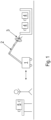
- FIG 1 a manufacturing plant for manufacturing a product, in particular a geared motor, is schematically sketched from a first component, in particular an electric motor 4, and a second component, in particular a transmission 5.
- the first components 4 are kept in stock in a container from which they can be removed by means of a robot arm 2 on which a gripping tool is arranged.
- the recording of the first component 4 is controlled by a controller, which is also supplied with the signals from an image recognition unit.
- the tool thus takes one of the first components 4 out of the container.
- the robot arm 2 Since the robot arm 2 is arranged on a vehicle 1 that can be moved on the ground, the robot arm 2 together with the first component 4 that is accommodated is arranged so that it can be moved and can be moved to a work area of an operator.
- the vehicle 1 has a drive.
- a second component 5 for example a gearbox, is arranged on a workbench. This second component 5 has to be connected to the first component 4 .
- the first and second components (4, 5) are centered on one another and then screw-connected.
- the vehicle is initially in autonomous operation together with the robot arm 2 .
- the first component 4 in the supply ie the container, is recognized by the image recognition unit and picked up by the robot arms 2 .
- the vehicle 1 then travels a distance in order to get closer to the operator or the intended starting position.
- the operator ie worker and/or worker, actuates an input means, selecting at least one of two human-controlled operating modes.
- the mode of operation initially selected by him is moving the vehicle 1, with the robot arm 2 is held immobile. To do this, the operator pulls on the sensor ring with a small force, so that the vehicle moves according to this pulling.
- the sensor signal of the sensor ring 3 is fed to the controller, which instructs the drives of the robot arm 2 to remain in their respective angular position, i.e. specifies the actual positions recorded when the input means is actuated as target positions for the drives of the robot arm 2.
- the action of the operator on the sensor ring 3 thus causes only a process of the drive of the vehicle that is dependent thereon. For example, in this operating mode, the operator can pull the vehicle 1 closer to him or move it to a desired position, with only a very small amount of effort being required, namely the actuation of the sensor ring 3.
- the operator then actuates the input means again, so that the other of the two human-guided operating modes is selected.
- the brake of the vehicle 1 is actuated and/or the actual value of the position of the drive of the vehicle 1 when the input means is actuated is specified as the target position for the drive of the vehicle 1 .
- the vehicle 1 thus stops.
- the operator touches the sensor ring 3 connected to the robot arm 2 and then guides the robot arm 2 together with the picked-up first component 4 to the second component 5 with extremely little effort and/or torque.
- the operator has to carry out a relative fine adjustment and centering of the two components (4, 5) relative to each other with this little effort.
- the sensor signals detected by the sensor ring are fed to the controller, which controls the robot arm in such a way that the picked-up second component 5 is moved in accordance with the direction of the detected force, with the mass or moment of inertia appearing effectively reduced for the operator.
- the operator is thus able to bring a first component 4, which has a very large mass, to the second component 5 with extremely little effort and then to connect the two components (4, 5) to form a product, in particular a screw connection to carry out with little effort.
- the drives of the robot arm 2 are regulated towards target values, which are changed according to the sensor signals of the sensor ring 3 .
- the vehicle is provided with a secondary winding on its underside, which can be inductively coupled to a primary conductor laid on the floor, to which a medium-frequency alternating current can be applied.
- the center frequency here is preferably between 10 kHz and 1000 kHz.
- the secondary winding has such a capacitance connected in series and/or in series that the resonant frequency of the resonant circuit formed in this way essentially corresponds to the frequency of the alternating current impressed on the primary conductor.
- the primary conductor is laid on the ground along the route of the vehicle.
- the primary conductor is designed as a winding, in particular as a ring winding.
- the floor does not have to be milled along the roadway of the vehicle to enable the primary conductor to be laid, but only in the area of the compact area of the winding.
- the energy store of the vehicle can thus be charged in the spatial area around the winding in which sufficient inductive coupling between the primary winding and the secondary winding of the vehicle can be achieved, and the vehicle, in particular its drive, the controller and the drives of the robot arm, can be loaded outside of the spatial area mentioned , can be supplied from the energy store.
Landscapes
- Engineering & Computer Science (AREA)
- Robotics (AREA)
- Mechanical Engineering (AREA)
- Human Computer Interaction (AREA)
- Health & Medical Sciences (AREA)
- General Health & Medical Sciences (AREA)
- Orthopedic Medicine & Surgery (AREA)
- Manipulator (AREA)
Description
- Die Erfindung betrifft ein Verfahren zum Betreiben einer Fertigungsanlage.
- Es ist allgemein bekannt, dass bei einer Fertigungsanlage zur Herstellung eines Produktes Komponenten zu verbinden sind.
- Aus dem Dokument "Robot Assistants at Manual Workplaces: Effective Co-operation and Safety Aspects" (Martin Hägele ET AL, 2002) ist als nächstliegender Stand der Technik ein Assistenzroboter bekannt.
- Aus dem Dokument "Montage am kontinuierlich bewegten Band" (F Lange ET AL, 2008) ist eine Fertigungsanlage mit Band bekannt.
- Aus dem Dokument "Move Over, Rover - Here Comes Justin the Robot" (youtube, 6. Juni 2011: https://www.youtube.com/watch?v=kBAqsTpcHEE) ist ein Roboter bekannt.
- Aus der
DE 10 2014 217352 ist eine verfahrbare Vorrichtung zur Manipulation von Gegenständen bekannt. - Aus dem Dokument "PowerMate - A Safe and Intuitive Robot Assistant for Handling and Assembly Tasks" (SCHRAFT R D ET AL, 2005) ist ein intuitives Robotersystem bekannt.
- Aus der
US 6 430 473 B1 ist ein Assistenzroboter bekannt. - Der Erfindung liegt daher die Aufgabe zugrunde, ein Verfahren zum Betreiben einer ergonomischen Fertigungsanlage weiterzubilden.
- Erfindungsgemäß wird die Aufgabe durch ein Verfahren nach den in Anspruch 1 angegebenen Merkmalen gelöst.
- Von Vorteil ist dabei, dass in der ersten Betriebsart ein automatisches Erkennen und Aufnehmen einer Komponente ausführbar ist und dann ein automatisches Herantransportieren ausführbar ist. danach ist vom Bediener ein Mensch-geführtes Verfahren des Fahrzeugs mit steif gestelltem Roboterarm ausführbar, also die zweite Betriebsart, oder alternativ vom Bediener ein Mensch-geführtes Bewegen des Roboterarms mit fixiertem Fahrzeug, also die dritte Betriebsart.
- Bei einer vorteilhaften Ausgestaltung werden in der zweiten und in der dritten Betriebsart die Antriebe des Roboterarms und/oder der Antrieb des Fahrzeugs in Lageregelung betrieben,
insbesondere also jedem der Antriebe jeweils eine Sollposition vorgegeben wird und die jeweilige Istposition des jeweiligen Antriebs erfasst wird und auf die Sollposition hin geregelt wird, insbesondere indem der Antrieb ein von dem zeitlichen Verlauf der Differenz zwischen Istposition und Sollposition abhängiges Drehmoment erzeugt. Von Vorteil ist dabei, dass im autonomen Betrieb keine Lageregelung, sondern beispielsweise eine Drehmomentenregelung oder eine Drehzahlregelung ausführbar ist. Erst bei Mensch-geführten Betriebsarten wird die Lageregelung ausgeführt, wobei die Sollposition vom Menschen mittels des Sensorrings veränderbar ist, insbesondere verschiebbar. - Wichtige Merkmale der Erfindung bei einer zur Durchführung des Verfahrens verwendbaren Fertigungsanlage zur Herstellung eines Produktes, insbesondere Getriebemotors, aus einer ersten Komponente, insbesondere Elektromotor, und aus einer zweiten Komponente, insbesondere Getriebe, sind, dass die Fertigungsanlage einen Roboterarm aufweist, welcher auf einem insbesondere auf einem Boden der Fertigungsanlage, verfahrbaren Fahrzeug angeordnet ist,
wobei ein Sensorring mit dem Roboterarm verbunden ist zur kraftarmen Führung einer vom Roboterarm aufgenommenen ersten Komponente. - Von Vorteil ist dabei, dass eine ergonomische Fertigung ausführbar ist. Denn der Bediener muss nur geringen Kraftaufwand aufbringen, auch wenn Komponenten mit großer Masse zu bewegen sind. Das Fahrzeug fungiert dabei als Assistent und bewegt die schwere Masse gemäß der Vorgabe des Bedieners. Mit anderen Worten ausgedrückt, ist die erfindungsgemäße Fertigungsanlage mit fahrbarem Roboterarm als Assistent bei der Montage vorgesehen, wobei eine erste Komponente vom Roboterarm aufgenommen und zu einem Bediener gefahren wird, der dann durch Führen eines am Roboterarm befestigten Sensorrings die erste Komponente zu einer stationär gelagerten zweiten Komponente heranführt und die beiden Kompoenten verbindet.
- Bei einer vorteilhaften Ausgestaltung ist eine Bilderkennungseinheit auf dem Fahrzeug angeordnet, welche mit der den Roboterarm steuernden Steuerung verbunden ist, insbesondere wobei mittels der Bilderkennungseinheit eine erste Komponente erkennbar ist und somit der Roboterarm zum Aufnehmen der ersten Komponente entsprechend steuerbar ist. Von Vorteil ist dabei, dass mittels der Bilderkennungseinheit eine erste Komponente erkennbar ist. Beispielsweise werden die Komponenten in einem Behältnis angeliefert und mittels der Bilderkennungseinheit erkannt, so dass die erste Komponente mittels des Greifwerkzeugs des Roboterarms aufnehmbar ist.
- Bei einer vorteilhaften Ausgestaltung weist der Roboterarm mehrere Antriebe auf, welche mit der Steuerung verbunden sind, welche eingerichtet ist, die Bewegung des Roboterarm zu steuern. Von Vorteil ist dabei, dass der Roboterarm als Assistenz fungiert.
- Bei einer vorteilhaften Ausgestaltung ist ein Eingabemittel zum wahlweisen Betrieb des Antriebs des Fahrzeugs oder der Antriebe des Roboterarms vorgesehen,
- wobei bei Auswahl des Betriebs des Antriebs des Fahrzeugs der Antrieb das Fahrzeug auf eine Sollposition hinsteuert, welche abhängig vom Signal des Sensorrings verschoben wird, und die Antriebe des Roboterarms ihre jeweilige Position, insbesondere Winkelposition, beibehalten,
- wobei bei Auswahl des Betriebs der Antriebe des Roboterarms diese Antriebe auf eine jeweilige Sollposition, insbesondere jeweilige Winkelposition, hinsteuert, welche abhängig vom Signal des Sensorrings verschoben werden, und der Antrieb des Fahrzeugs seine Position beibehält und/oder eine Bremse des Fahrzeugs aktiviert ist. Von Vorteil ist dabei, dass entweder das Fahrzeug bei steif gestelltem Roboterarm verschiebbar ist oder dass der Roboterarm bewegbar ist bei fest positioniertem Fahrzeug.
- Bei einer vorteilhaften Ausgestaltung ist die aufgenommene erste Komponente mittels des Roboterarms zu einer stationär gelagerten, zweiten Komponente hin führbar und an dieser zentrierbar ohne wesentlichen Kraftaufwand,
insbesondere zum Verbinden, insbesondere Schraubverbinden, der ersten mit der zweiten Komponente. Von Vorteil ist dabei, dass ein ergonomisches Arbeiten, insbesondere ohne großen Kraftaufwand, ermöglicht ist. - Bei einer vorteilhaften Ausgestaltung weist das Fahrzeug eine Sekundärwicklung auf, welche zur Übertragung elektrischer Energie mit einem am Boden angeordneten Primärleiter induktiv koppelbar ist, insbesondere zur resonanten Übertragung elektrischer Energie. Von Vorteil ist dabei, dass eine berührungslose Energieversorgung ermöglicht ist.
- Bei einer vorteilhaften Ausgestaltung ist der Sekundärwicklung eine derartige Kapazität in Reihe oder parallel zugeschaltet, dass die Resonanzfrequenz des so gebildeten Schwingkreises der Frequenz des in den Primärleiter eingeprägten Wechselstroms entspricht. Von Vorteil ist dabei, dass ein hoher Wirkungsgrad trotz schwacher Kopplungsstärke erreichbar ist.
- Bei einer vorteilhaften Ausgestaltung ist der Primärleiter als Primärwicklung ausgeführt, so dass das Fahrzeug nur in einem ersten Raumbereich aus dem Primärleiter induktiv versorgbar ist,
wobei das Fahrzeug einen Energiespeicher aufweist zur Versorgung des Fahrzeugs außerhalb des Raumbereichs. Von Vorteil ist dabei, dass der Boden der Anlage nur geringfügig bearbeitet werden muss. - Bei einer vorteilhaften Ausgestaltung weist der Roboterarm ein Greifwerkzeug auf, wobei das Greifwerkzeug von der Steuerung steuerbar ist. Von Vorteil ist dabei, dass die erste Komponente vom Greifwerkzeug aufnehmbar ist und somit vom Roboterarm transportierbar ist.
- Bei einer vorteilhaften Ausgestaltung ist der Energiespeicher ein Doppelschichtkondensator, insbesondere Ultracap. Von Vorteil ist dabei, dass ein schnelles Aufladen ausführbar ist, also hohe Ladeströme erlaubt sind.
- Weitere Vorteile ergeben sich aus den Unteransprüchen.
- Die Erfindung wird nun anhand von Abbildungen näher erläutert:
In derFigur 1 ist eine Fertigungsanlage zur Herstellung eines Produktes, insbesondere Getriebemotors, aus einer ersten Komponente, insbesondere Elektromotor 4, und aus einer zweiten Komponente, insbesondere Getriebe 5, schematisch skizziert. - Hierbei sind die ersten Komponenten 4 in einem Behältnis vorrätig gehalten, aus dem sie mittels eines Roboterarms 2, an welchem ein Greifwerkzeug angeordnet ist, entnehmbar sind.
- Das Aufnehmen der ersten Komponente 4 wird dabei von einer Steuerung gesteuert, der auch die Signale einer Bilderkennungseinheit zugeführt werden. Somit greift das Werkzeug eine der ersten Komponenten 4 aus dem Behältnis heraus.
- Da der Roboterarm 2 auf einem bodengängig verfahrbaren Fahrzeug 1 angeordnet ist, ist der Roboterarm 2 samt aufgenommener erster Komponente 4 verfahrbar angeordnet und zu einem Arbeitsbereich eines Bedieners hin verfahrbar. Hierzu weist das Fahrzeug 1 einen Antrieb auf.
- Auf einem Werktisch ist eine zweite Komponente 5, beispielsweise ein Getriebe, angeordnet. Diese zweite Komponente 5 muss mit der ersten Komponente 4 verbunden werden. Im Beispiel werden die erste und zweite Komponente (4, 5) aneinander zentriert und dann schraubverbunden.
- Wie oben beschrieben, ist das Fahrzeug zunächst samt Roboterarm 2 in autonomem Betrieb. Mittels der Bilderkennungseinheit wird die erste Komponente 4 in dem Vorrat, also Behältnis, erkannt und vom Roboterarme 2 aufgenommen. Das Fahrzeug 1 fährt danach eine Wegstrecke, um näher an den Bediener oder die vorgesehene Startposition zu gelangen.
- Der Bediener, also Arbeiter und/oder Werker, betätigt ein Eingabemittel, wobei er zumindest eines von zwei Mensch-geführten Betriebsarten auswählt. Dabei ist die von ihm zunächst ausgewählte Betriebsart ein Bewegen des Fahrzeugs 1, wobei der Roboterarm 2 unbeweglich gehalten wird. Hierzu zieht der Bediener am Sensorring mit einer kleinen Kraft, so dass das Fahrzeug entsprechend diesem Ziehen sich bewegt. Dabei wird das Sensorsignal des Sensorrings 3 der Steuerung zugeführt, welche den Antrieben des Roboterarms 2 vorgibt, in ihrer jeweiligen Winkelposition zu verbleiben, also die jeweils bei Betätigen des Eingabemittels erfassten Istpositionen als Sollpositionen für die Antriebe des Roboterarms 2 vorgibt. Die Einwirkung des Bedieners auf den Sensorring 3 bewirkt also nur ein davon abhängiges Verfahren des Antriebs des Fahrzeugs. Beispielsweise kann der Bediener das Fahrzeug 1 in dieser Betriebsart zu sich näher heranziehen oder zu einer gewünschten Position verschieben, wobei nur ein sehr geringer Kraftaufwand notwendig ist, nämlich die Betätigung des Sensorrings 3.
- Danach betätigt der Bediener wiederum das Eingabemittel, so dass die andere der beiden Mensch-geführten Betriebsarten ausgewählt wird. Hierbei wird die Bremse des Fahrzeugs 1 betätigt und/oder der beim Betätigen des Eingabemittels vorhandene Istwert der Position des Antriebs des Fahrzeugs 1 als Sollposition für den Antrieb des Fahrzeugs 1 vorgegeben. Somit bleibt das Fahrzeug 1 stehen. Der Bediener berührt den mit dem Roboterarm 2 verbundenen Sensorring 3 und führt dann mit äußerst wenig Aufwand an Kraft und/oder Drehmoment den Roboterarm 2 samt der aufgenommenen ersten Komponente 4 zur zweiten Komponente 5. Dabei ist vom Bediener eine relative Feinjustierung und Zentrierung der beiden Komponenten (4, 5) relativ zueinander mit diesem geringen Aufwand ausführbar.
- Hierzu werden die vom Sensorring erfassten Sensorsignale der Steuerung zugeführt, welche den Roboterarm derart steuert, dass die aufgenommene zweite Komponente 5 entsprechend der Richtung der detektierten Kraft bewegt wird, wobei Masse beziehungsweise Trägheitsmoment für den Bediener effektiv vermindert erscheinen. Somit ist der Bediener in der Lage, eine erste Komponente 4, welche eine sehr große Masse aufweist, mit äußerst geringem Kraftaufwand an die zweite Komponente 5 heranzuführen und dann die Verbindung der beiden Komponenten (4, 5) zu einem Produkt, insbesondere Schraubverbindung, mit geringem Aufwand auszuführen. Hierzu werden die Antriebe des Roboterarms 2 auf Sollwerte hin geregelt, welche entsprechend der Sensorsignale des Sensorrings 3 verändert werden.
- Somit ist mittels des Eingabemittels zwischen der autonomen und den beiden Mensch-geführten Betriebsarten umschaltbar.
- Das Fahrzeug ist an seiner Unterseite mit einer Sekundärwicklung vorgesehen, welche induktiv koppelbar ist mit einem am Boden verlegten Primärleiter, der mit einem mittelfrequenten Wechselstrom beaufschlagbar ist. Die Mittelfrequenz liegt hierbei vorzugsweise zwischen 10 kHz und 1000 kHz. Der Sekundärwicklung ist eine derartige Kapazität in Reihe und/oder seriell zugeschaltet, dass die Resonanzfrequenz des so gebildeten Schwingkreises im Wesentlichen der Frequenz des in den Primärleiter eingeprägten Wechselstroms entspricht.
- Somit ist eine induktive Versorgung des Fahrzeugs 1 ermöglicht.
- Der Primärleiter ist entlang der Fahrstrecke des Fahrzeugs am Boden verlegt.
- Bei einem weiteren erfindungsgemäßen Ausführungsbeispiel ist der Primärleiter als Wicklung ausgeführt, insbesondere als Ringwicklung.
- Somit muss der Boden nicht langgestreckt entlang der Fahrbahn des Fahrzeugs aufgefräst werden zur Ermöglichung der Verlegung des Primärleiters, sondern nur im Bereich des kompakten Bereiches der Wicklung. In demjenigen Raumbereich um die Wicklung herum, in welchem eine ausreichende induktive Kopplung zwischen Primärwicklung und Sekundärwicklung des Fahrzeugs erreichbar ist, ist somit der Energiespeicher des Fahrzeugs beladbar und außerhalb des genannten Raumbereichs ist das Fahrzeug, insbesondere dessen Antrieb, die Steuerung und die Antriebe des Roboterarms, aus dem Energiespeicher versorgbar.
-
- 1 Fahrzeug mit Roboterarm
- 2 Roboterarm
- 3 Sensorring
- 4 Elektromotor
- 5 Getriebe
Claims (2)
- Verfahren zum Betreiben einer Fertigungsanlage zur Herstellung eines Produktes, insbesondere Getriebemotors, aus einer ersten Komponente, insbesondere Elektromotor (4), und aus einer zweiten, stationär gelagerten Komponente, insbesondere Getriebe,wobei die Fertigungsanlage einen Roboterarm (2) aufweist, welcher auf einem insbesondere auf einem Boden der Fertigungsanlage, verfahrbaren Fahrzeug (1) angeordnet ist,wobei ein Sensorring (3) mit dem Roboterarm (2) verbunden ist zur kraftarmen Führung einer vom Roboterarm (2) aufgenommenen ersten Komponente,dadurch gekennzeichnet, dassmittels eines Eingabemittels eine erste, zweite oder dritte Betriebsart derart ausgewählt wird, so dass abhängig von der Betätigung des Eingabemittels- in einem ersten Verfahrensschritt in der ersten Betriebsart das Fahrzeug (1) samt Roboterarm (2) autonom betrieben wird, insbesondere von der Steuerung gesteuert wird,- in einem zweiten auf den ersten Verfahrensschritt zeitlich nachfolgenden Verfahrensschritt in der zweiten Betriebsart ein derartiges Mensch-geführtes Betreiben ausgeführt wird, dass abhängig von den Sensorsignalen des Sensorrings (3) die für den Antrieb des Fahrzeugs (1) vorgegebene Sollposition verändert wird, wobei als jeweilige Sollpositionen der jeweiligen Antriebe des Roboterarms (2) konstante Werte vorgegeben werden, wobei die bei Betätigen des Eingabemittels zum Auswählen der zweiten Betriebsart vorhandenen Istpositionen der jeweiligen Antriebe des Roboterarms (2) als Sollpositionen der jeweiligen Antriebe des Roboterarms (2) vorgegeben wird,- in einem dritten auf den zweiten Verfahrensschritt zeitlich nachfolgenden Verfahrensschritt in der dritten Betriebsart ein derartiges Mensch-geführtes Betreiben ausgeführt wird, dass abhängig von den Sensorsignalen des Sensorrings (3) die jeweiligen Sollpositionen der jeweiligen Antriebe des Roboterarms (2) verändert werden, wobei eine Bremse des Fahrzeugs (1) betätigt wird /oder als Sollposition für den Antrieb des Fahrzeugs (1) ein konstanter Wert vorgegeben wird, wobei die bei Betätigen des Eingabemittels zum Auswählen der dritten Betriebsart vorhandene Istposition des Antriebs des Fahrzeugs (1) als Sollposition des Antriebs des Fahrzeugs (1) vorgegeben wird,wobei die aufgenommene erste Komponente mittels des Roboterarms (2) zu der stationär gelagerten, zweiten Komponente hingeführt wird und an dieser zentriert wird ohne wesentlichen Kraftaufwand, zum Verbinden, insbesondere Schraubverbinden, der ersten mit der zweiten Komponente.
- Verfahren nach Anspruch 1,
dadurch gekennzeichnet, dassin der zweiten und in der dritten Betriebsart die Antriebe des Roboterarms (2) und/oder der Antrieb des Fahrzeugs (1) in Lageregelung betrieben werden,insbesondere also jedem der Antriebe jeweils eine Sollposition vorgegeben wird und die jeweilige Istposition des jeweiligen Antriebs erfasst wird und auf die Sollposition hin geregelt wird, insbesondere indem der Antrieb ein von dem zeitlichen Verlauf der Differenz zwischen Istposition und Sollposition abhängiges Drehmoment erzeugt.
Priority Applications (1)
| Application Number | Priority Date | Filing Date | Title |
|---|---|---|---|
| EP22000208.3A EP4134206B1 (de) | 2016-04-22 | 2017-03-28 | Fertigungsanlage und verfahren zum betreiben einer fertigungsanlage |
Applications Claiming Priority (2)
| Application Number | Priority Date | Filing Date | Title |
|---|---|---|---|
| DE102016004975 | 2016-04-22 | ||
| PCT/EP2017/025065 WO2017182133A1 (de) | 2016-04-22 | 2017-03-28 | Fertigungsanlage und verfahren zum betreiben einer fertigungsanlage |
Related Child Applications (2)
| Application Number | Title | Priority Date | Filing Date |
|---|---|---|---|
| EP22000208.3A Division-Into EP4134206B1 (de) | 2016-04-22 | 2017-03-28 | Fertigungsanlage und verfahren zum betreiben einer fertigungsanlage |
| EP22000208.3A Division EP4134206B1 (de) | 2016-04-22 | 2017-03-28 | Fertigungsanlage und verfahren zum betreiben einer fertigungsanlage |
Publications (3)
| Publication Number | Publication Date |
|---|---|
| EP3445532A1 EP3445532A1 (de) | 2019-02-27 |
| EP3445532B1 true EP3445532B1 (de) | 2023-06-07 |
| EP3445532C0 EP3445532C0 (de) | 2023-06-07 |
Family
ID=58461261
Family Applications (2)
| Application Number | Title | Priority Date | Filing Date |
|---|---|---|---|
| EP22000208.3A Active EP4134206B1 (de) | 2016-04-22 | 2017-03-28 | Fertigungsanlage und verfahren zum betreiben einer fertigungsanlage |
| EP17714644.6A Active EP3445532B1 (de) | 2016-04-22 | 2017-03-28 | Verfahren zum betreiben einer fertigungsanlage |
Family Applications Before (1)
| Application Number | Title | Priority Date | Filing Date |
|---|---|---|---|
| EP22000208.3A Active EP4134206B1 (de) | 2016-04-22 | 2017-03-28 | Fertigungsanlage und verfahren zum betreiben einer fertigungsanlage |
Country Status (3)
| Country | Link |
|---|---|
| EP (2) | EP4134206B1 (de) |
| DE (1) | DE102017002963B4 (de) |
| WO (1) | WO2017182133A1 (de) |
Families Citing this family (5)
| Publication number | Priority date | Publication date | Assignee | Title |
|---|---|---|---|---|
| WO2021180486A1 (de) | 2020-03-13 | 2021-09-16 | Sew-Eurodrive Gmbh & Co. Kg | Verfahren zum betreiben einer technischen anlage und technische anlage |
| EP4153510B1 (de) | 2020-05-20 | 2025-06-11 | Sew-Eurodrive GmbH & Co. KG | Verfahren zum betreiben einer technischen anlage und technische anlage |
| CN112246687A (zh) * | 2020-10-22 | 2021-01-22 | 荆楚理工学院 | 一种垃圾分类小车 |
| WO2022258366A1 (de) | 2021-06-07 | 2022-12-15 | Sew-Eurodrive Gmbh & Co. Kg | Verfahren und system zur unterstützung eines arbeitsschritts bei der herstellung eines produkts |
| WO2023208415A1 (de) | 2022-04-26 | 2023-11-02 | Sew-Eurodrive Gmbh & Co. Kg | Technische anlage zur herstellung von produkten und verfahren zum betreiben einer technischen anlage |
Family Cites Families (5)
| Publication number | Priority date | Publication date | Assignee | Title |
|---|---|---|---|---|
| JP3188953B2 (ja) * | 1999-10-13 | 2001-07-16 | 経済産業省産業技術総合研究所長 | パワーアシスト装置およびその制御方法 |
| JP4517726B2 (ja) * | 2004-05-25 | 2010-08-04 | 株式会社安川電機 | アシスト装置 |
| JP5446573B2 (ja) * | 2009-08-13 | 2014-03-19 | 株式会社Ihi | ロボット制御装置及びロボット操作用デバイス |
| DE102012103515A1 (de) * | 2012-04-20 | 2013-10-24 | Demag Cranes & Components Gmbh | Steuerverfahren für ein Balancier-Hebezeug und Balancier-Hebezeug hiermit |
| DE102014217352B4 (de) * | 2014-08-29 | 2018-04-19 | HAP Handhabungs-, Automatisierungs- und Präzisionstechnik GmbH | Verfahrbare Vorrichtung zur Manipulation von Gegenständen |
-
2017
- 2017-03-28 EP EP22000208.3A patent/EP4134206B1/de active Active
- 2017-03-28 EP EP17714644.6A patent/EP3445532B1/de active Active
- 2017-03-28 WO PCT/EP2017/025065 patent/WO2017182133A1/de not_active Ceased
- 2017-03-28 DE DE102017002963.6A patent/DE102017002963B4/de active Active
Also Published As
| Publication number | Publication date |
|---|---|
| EP4134206C0 (de) | 2023-11-22 |
| EP3445532C0 (de) | 2023-06-07 |
| EP4134206B1 (de) | 2023-11-22 |
| EP4134206A1 (de) | 2023-02-15 |
| WO2017182133A1 (de) | 2017-10-26 |
| DE102017002963A1 (de) | 2017-10-26 |
| EP3445532A1 (de) | 2019-02-27 |
| DE102017002963B4 (de) | 2025-04-17 |
Similar Documents
| Publication | Publication Date | Title |
|---|---|---|
| EP3445532B1 (de) | Verfahren zum betreiben einer fertigungsanlage | |
| DE102008062622B4 (de) | Verfahren und Vorrichtung zur Befehlseingabe in eine Steuerung eines Manipulators | |
| DE69723791T2 (de) | Rohrmolch | |
| EP4046755B1 (de) | Vorrichtung und verfahren zum automatisierten entnehmen von in einem behälter angeordneten werkstücken | |
| EP2631043B1 (de) | Verfahren und Vorrichtung zum Ausführen eines Manipulatorprozesses | |
| DE102011109531B4 (de) | Anlage zur Energieversorgung einer Maschine mittels eines Mobilteils und Verfahren zum Betreiben einer Anlage | |
| WO2010069429A1 (de) | Verfahren und vorrichtung zur befehlseingabe in eine steuerung eines manipulators | |
| DE3324739A1 (de) | Steuersystem fuer automaten mit direktanleitung und nachvollzug | |
| EP2577414B1 (de) | Verfahren und steuerungssystem zum programmieren oder vorgeben von bewegungen oder abläufen eines industrieroboters | |
| EP3277519B1 (de) | Lagersystem mit einem omnidirektionalen fahrzeug und verfahren zum betreiben eines solchen lagersystems | |
| DE102004038310A1 (de) | Lasereinrichtung und Betriebsverfahren | |
| DE102017109818A1 (de) | Ladeportal | |
| EP3333116A1 (de) | Verfahren zur automatischen ausrichtung eines flurförderzeugs in einem warenlager sowie system aus einem flurförderzeug und einem warenlager | |
| EP2431114B9 (de) | Drehmaschine mit einer Leit- und Zugspindel und einer elektronischen Steuerung für den Längs- und/oder Planschlitten | |
| EP3416401A1 (de) | Mobiles transportmittel zum transportieren von datensammlern, datensammelsystem und datensammelverfahren | |
| DE112021002948B4 (de) | Unabhängiges robotersicherheitssystem mit einer sicherheitsbewerteten sps | |
| DE202014100334U1 (de) | Roboterwerkzeug | |
| WO2017137558A1 (de) | Verfahren und anordnung zur hochgenauen positionierung einer robotergeführten interaktionsvorrichtung mittels radar | |
| DE102015117306B4 (de) | Mehrachs-Maus für einen Mehrachsroboter | |
| DE102012004059B4 (de) | Anlage zur Herstellung eines Produktes und Verfahren | |
| WO2020193340A1 (de) | Robotergreifer sowie verfahren zum betrieb eines robotergreifers | |
| DE3533275C2 (de) | ||
| EP3468753B1 (de) | Verfahren zum sicheren stillsetzen eines manipulators | |
| WO2017182132A1 (de) | Verfahren zum herstellen in einer fertigungszelle einer fertigungsanlage und fertigungsanlage zur durchführung des verfahrens | |
| DE102021130535B3 (de) | System und Verfahren zur Positionierung einer bewegbaren Manipulatoreinheit |
Legal Events
| Date | Code | Title | Description |
|---|---|---|---|
| STAA | Information on the status of an ep patent application or granted ep patent |
Free format text: STATUS: UNKNOWN |
|
| STAA | Information on the status of an ep patent application or granted ep patent |
Free format text: STATUS: THE INTERNATIONAL PUBLICATION HAS BEEN MADE |
|
| PUAI | Public reference made under article 153(3) epc to a published international application that has entered the european phase |
Free format text: ORIGINAL CODE: 0009012 |
|
| STAA | Information on the status of an ep patent application or granted ep patent |
Free format text: STATUS: REQUEST FOR EXAMINATION WAS MADE |
|
| 17P | Request for examination filed |
Effective date: 20181122 |
|
| AK | Designated contracting states |
Kind code of ref document: A1 Designated state(s): AL AT BE BG CH CY CZ DE DK EE ES FI FR GB GR HR HU IE IS IT LI LT LU LV MC MK MT NL NO PL PT RO RS SE SI SK SM TR |
|
| AX | Request for extension of the european patent |
Extension state: BA ME |
|
| DAV | Request for validation of the european patent (deleted) | ||
| DAX | Request for extension of the european patent (deleted) | ||
| STAA | Information on the status of an ep patent application or granted ep patent |
Free format text: STATUS: EXAMINATION IS IN PROGRESS |
|
| 17Q | First examination report despatched |
Effective date: 20211012 |
|
| GRAP | Despatch of communication of intention to grant a patent |
Free format text: ORIGINAL CODE: EPIDOSNIGR1 |
|
| STAA | Information on the status of an ep patent application or granted ep patent |
Free format text: STATUS: GRANT OF PATENT IS INTENDED |
|
| INTG | Intention to grant announced |
Effective date: 20230112 |
|
| GRAS | Grant fee paid |
Free format text: ORIGINAL CODE: EPIDOSNIGR3 |
|
| GRAA | (expected) grant |
Free format text: ORIGINAL CODE: 0009210 |
|
| STAA | Information on the status of an ep patent application or granted ep patent |
Free format text: STATUS: THE PATENT HAS BEEN GRANTED |
|
| AK | Designated contracting states |
Kind code of ref document: B1 Designated state(s): AL AT BE BG CH CY CZ DE DK EE ES FI FR GB GR HR HU IE IS IT LI LT LU LV MC MK MT NL NO PL PT RO RS SE SI SK SM TR |
|
| REG | Reference to a national code |
Ref country code: GB Ref legal event code: FG4D Free format text: NOT ENGLISH |
|
| REG | Reference to a national code |
Ref country code: CH Ref legal event code: EP Ref country code: AT Ref legal event code: REF Ref document number: 1573593 Country of ref document: AT Kind code of ref document: T Effective date: 20230615 Ref country code: DE Ref legal event code: R096 Ref document number: 502017014834 Country of ref document: DE |
|
| U01 | Request for unitary effect filed |
Effective date: 20230612 |
|
| U07 | Unitary effect registered |
Designated state(s): AT BE BG DE DK EE FI FR IT LT LU LV MT NL PT SE SI Effective date: 20230627 |
|
| REG | Reference to a national code |
Ref country code: LT Ref legal event code: MG9D |
|
| PG25 | Lapsed in a contracting state [announced via postgrant information from national office to epo] |
Ref country code: NO Free format text: LAPSE BECAUSE OF FAILURE TO SUBMIT A TRANSLATION OF THE DESCRIPTION OR TO PAY THE FEE WITHIN THE PRESCRIBED TIME-LIMIT Effective date: 20230907 Ref country code: ES Free format text: LAPSE BECAUSE OF FAILURE TO SUBMIT A TRANSLATION OF THE DESCRIPTION OR TO PAY THE FEE WITHIN THE PRESCRIBED TIME-LIMIT Effective date: 20230607 |
|
| PG25 | Lapsed in a contracting state [announced via postgrant information from national office to epo] |
Ref country code: RS Free format text: LAPSE BECAUSE OF FAILURE TO SUBMIT A TRANSLATION OF THE DESCRIPTION OR TO PAY THE FEE WITHIN THE PRESCRIBED TIME-LIMIT Effective date: 20230607 Ref country code: HR Free format text: LAPSE BECAUSE OF FAILURE TO SUBMIT A TRANSLATION OF THE DESCRIPTION OR TO PAY THE FEE WITHIN THE PRESCRIBED TIME-LIMIT Effective date: 20230607 Ref country code: GR Free format text: LAPSE BECAUSE OF FAILURE TO SUBMIT A TRANSLATION OF THE DESCRIPTION OR TO PAY THE FEE WITHIN THE PRESCRIBED TIME-LIMIT Effective date: 20230908 |
|
| PG25 | Lapsed in a contracting state [announced via postgrant information from national office to epo] |
Ref country code: SK Free format text: LAPSE BECAUSE OF FAILURE TO SUBMIT A TRANSLATION OF THE DESCRIPTION OR TO PAY THE FEE WITHIN THE PRESCRIBED TIME-LIMIT Effective date: 20230607 |
|
| PG25 | Lapsed in a contracting state [announced via postgrant information from national office to epo] |
Ref country code: IS Free format text: LAPSE BECAUSE OF FAILURE TO SUBMIT A TRANSLATION OF THE DESCRIPTION OR TO PAY THE FEE WITHIN THE PRESCRIBED TIME-LIMIT Effective date: 20231007 |
|
| PG25 | Lapsed in a contracting state [announced via postgrant information from national office to epo] |
Ref country code: SM Free format text: LAPSE BECAUSE OF FAILURE TO SUBMIT A TRANSLATION OF THE DESCRIPTION OR TO PAY THE FEE WITHIN THE PRESCRIBED TIME-LIMIT Effective date: 20230607 Ref country code: SK Free format text: LAPSE BECAUSE OF FAILURE TO SUBMIT A TRANSLATION OF THE DESCRIPTION OR TO PAY THE FEE WITHIN THE PRESCRIBED TIME-LIMIT Effective date: 20230607 Ref country code: RO Free format text: LAPSE BECAUSE OF FAILURE TO SUBMIT A TRANSLATION OF THE DESCRIPTION OR TO PAY THE FEE WITHIN THE PRESCRIBED TIME-LIMIT Effective date: 20230607 Ref country code: IS Free format text: LAPSE BECAUSE OF FAILURE TO SUBMIT A TRANSLATION OF THE DESCRIPTION OR TO PAY THE FEE WITHIN THE PRESCRIBED TIME-LIMIT Effective date: 20231007 Ref country code: CZ Free format text: LAPSE BECAUSE OF FAILURE TO SUBMIT A TRANSLATION OF THE DESCRIPTION OR TO PAY THE FEE WITHIN THE PRESCRIBED TIME-LIMIT Effective date: 20230607 |
|
| PG25 | Lapsed in a contracting state [announced via postgrant information from national office to epo] |
Ref country code: PL Free format text: LAPSE BECAUSE OF FAILURE TO SUBMIT A TRANSLATION OF THE DESCRIPTION OR TO PAY THE FEE WITHIN THE PRESCRIBED TIME-LIMIT Effective date: 20230607 |
|
| REG | Reference to a national code |
Ref country code: DE Ref legal event code: R097 Ref document number: 502017014834 Country of ref document: DE |
|
| PLBE | No opposition filed within time limit |
Free format text: ORIGINAL CODE: 0009261 |
|
| STAA | Information on the status of an ep patent application or granted ep patent |
Free format text: STATUS: NO OPPOSITION FILED WITHIN TIME LIMIT |
|
| U20 | Renewal fee for the european patent with unitary effect paid |
Year of fee payment: 8 Effective date: 20240402 |
|
| 26N | No opposition filed |
Effective date: 20240308 |
|
| REG | Reference to a national code |
Ref country code: CH Ref legal event code: PL |
|
| PG25 | Lapsed in a contracting state [announced via postgrant information from national office to epo] |
Ref country code: MC Free format text: LAPSE BECAUSE OF FAILURE TO SUBMIT A TRANSLATION OF THE DESCRIPTION OR TO PAY THE FEE WITHIN THE PRESCRIBED TIME-LIMIT Effective date: 20230607 |
|
| PG25 | Lapsed in a contracting state [announced via postgrant information from national office to epo] |
Ref country code: MC Free format text: LAPSE BECAUSE OF FAILURE TO SUBMIT A TRANSLATION OF THE DESCRIPTION OR TO PAY THE FEE WITHIN THE PRESCRIBED TIME-LIMIT Effective date: 20230607 |
|
| PG25 | Lapsed in a contracting state [announced via postgrant information from national office to epo] |
Ref country code: IE Free format text: LAPSE BECAUSE OF NON-PAYMENT OF DUE FEES Effective date: 20240328 |
|
| PG25 | Lapsed in a contracting state [announced via postgrant information from national office to epo] |
Ref country code: IE Free format text: LAPSE BECAUSE OF NON-PAYMENT OF DUE FEES Effective date: 20240328 Ref country code: CH Free format text: LAPSE BECAUSE OF NON-PAYMENT OF DUE FEES Effective date: 20240331 |
|
| PGFP | Annual fee paid to national office [announced via postgrant information from national office to epo] |
Ref country code: GB Payment date: 20250206 Year of fee payment: 9 |
|
| U20 | Renewal fee for the european patent with unitary effect paid |
Year of fee payment: 9 Effective date: 20250331 |
|
| PG25 | Lapsed in a contracting state [announced via postgrant information from national office to epo] |
Ref country code: CY Free format text: LAPSE BECAUSE OF FAILURE TO SUBMIT A TRANSLATION OF THE DESCRIPTION OR TO PAY THE FEE WITHIN THE PRESCRIBED TIME-LIMIT; INVALID AB INITIO Effective date: 20170328 |
|
| PG25 | Lapsed in a contracting state [announced via postgrant information from national office to epo] |
Ref country code: HU Free format text: LAPSE BECAUSE OF FAILURE TO SUBMIT A TRANSLATION OF THE DESCRIPTION OR TO PAY THE FEE WITHIN THE PRESCRIBED TIME-LIMIT; INVALID AB INITIO Effective date: 20170328 |
|
| PG25 | Lapsed in a contracting state [announced via postgrant information from national office to epo] |
Ref country code: TR Free format text: LAPSE BECAUSE OF FAILURE TO SUBMIT A TRANSLATION OF THE DESCRIPTION OR TO PAY THE FEE WITHIN THE PRESCRIBED TIME-LIMIT Effective date: 20230607 |