EP3445462B1 - Self-propelled personal transportation device and control system - Google Patents
Self-propelled personal transportation device and control system Download PDFInfo
- Publication number
- EP3445462B1 EP3445462B1 EP17703943.5A EP17703943A EP3445462B1 EP 3445462 B1 EP3445462 B1 EP 3445462B1 EP 17703943 A EP17703943 A EP 17703943A EP 3445462 B1 EP3445462 B1 EP 3445462B1
- Authority
- EP
- European Patent Office
- Prior art keywords
- forces
- controller
- determining
- target
- transportation device
- Prior art date
- Legal status (The legal status is an assumption and is not a legal conclusion. Google has not performed a legal analysis and makes no representation as to the accuracy of the status listed.)
- Not-in-force
Links
Images






Classifications
-
- B—PERFORMING OPERATIONS; TRANSPORTING
- B62—LAND VEHICLES FOR TRAVELLING OTHERWISE THAN ON RAILS
- B62K—CYCLES; CYCLE FRAMES; CYCLE STEERING DEVICES; RIDER-OPERATED TERMINAL CONTROLS SPECIALLY ADAPTED FOR CYCLES; CYCLE AXLE SUSPENSIONS; CYCLE SIDECARS, FORECARS, OR THE LIKE
- B62K5/00—Cycles with handlebars, equipped with three or more main road wheels
- B62K5/01—Motorcycles with four or more wheels
-
- G—PHYSICS
- G05—CONTROLLING; REGULATING
- G05D—SYSTEMS FOR CONTROLLING OR REGULATING NON-ELECTRIC VARIABLES
- G05D1/00—Control of position, course, altitude or attitude of land, water, air or space vehicles, e.g. using automatic pilots
- G05D1/02—Control of position or course in two dimensions
- G05D1/021—Control of position or course in two dimensions specially adapted to land vehicles
- G05D1/0212—Control of position or course in two dimensions specially adapted to land vehicles with means for defining a desired trajectory
- G05D1/0223—Control of position or course in two dimensions specially adapted to land vehicles with means for defining a desired trajectory involving speed control of the vehicle
-
- G—PHYSICS
- G05—CONTROLLING; REGULATING
- G05D—SYSTEMS FOR CONTROLLING OR REGULATING NON-ELECTRIC VARIABLES
- G05D1/00—Control of position, course, altitude or attitude of land, water, air or space vehicles, e.g. using automatic pilots
- G05D1/0011—Control of position, course, altitude or attitude of land, water, air or space vehicles, e.g. using automatic pilots associated with a remote control arrangement
- G05D1/0016—Control of position, course, altitude or attitude of land, water, air or space vehicles, e.g. using automatic pilots associated with a remote control arrangement characterised by the operator's input device
-
- B—PERFORMING OPERATIONS; TRANSPORTING
- B60—VEHICLES IN GENERAL
- B60L—PROPULSION OF ELECTRICALLY-PROPELLED VEHICLES; SUPPLYING ELECTRIC POWER FOR AUXILIARY EQUIPMENT OF ELECTRICALLY-PROPELLED VEHICLES; ELECTRODYNAMIC BRAKE SYSTEMS FOR VEHICLES IN GENERAL; MAGNETIC SUSPENSION OR LEVITATION FOR VEHICLES; MONITORING OPERATING VARIABLES OF ELECTRICALLY-PROPELLED VEHICLES; ELECTRIC SAFETY DEVICES FOR ELECTRICALLY-PROPELLED VEHICLES
- B60L15/00—Methods, circuits, or devices for controlling the traction-motor speed of electrically-propelled vehicles
- B60L15/20—Methods, circuits, or devices for controlling the traction-motor speed of electrically-propelled vehicles for control of the vehicle or its driving motor to achieve a desired performance, e.g. speed, torque, programmed variation of speed
- B60L15/2036—Electric differentials, e.g. for supporting steering vehicles
-
- A—HUMAN NECESSITIES
- A63—SPORTS; GAMES; AMUSEMENTS
- A63C—SKATES; SKIS; ROLLER SKATES; DESIGN OR LAYOUT OF COURTS, RINKS OR THE LIKE
- A63C17/00—Roller skates; Skate-boards
- A63C17/01—Skateboards
- A63C17/011—Skateboards with steering mechanisms
-
- A—HUMAN NECESSITIES
- A63—SPORTS; GAMES; AMUSEMENTS
- A63C—SKATES; SKIS; ROLLER SKATES; DESIGN OR LAYOUT OF COURTS, RINKS OR THE LIKE
- A63C17/00—Roller skates; Skate-boards
- A63C17/01—Skateboards
- A63C17/011—Skateboards with steering mechanisms
- A63C17/012—Skateboards with steering mechanisms with a truck, i.e. with steering mechanism comprising an inclined geometrical axis to convert lateral tilting of the board in steering of the wheel axis
-
- A—HUMAN NECESSITIES
- A63—SPORTS; GAMES; AMUSEMENTS
- A63C—SKATES; SKIS; ROLLER SKATES; DESIGN OR LAYOUT OF COURTS, RINKS OR THE LIKE
- A63C17/00—Roller skates; Skate-boards
- A63C17/02—Roller skates; Skate-boards with wheels arranged in two pairs
-
- A—HUMAN NECESSITIES
- A63—SPORTS; GAMES; AMUSEMENTS
- A63C—SKATES; SKIS; ROLLER SKATES; DESIGN OR LAYOUT OF COURTS, RINKS OR THE LIKE
- A63C17/00—Roller skates; Skate-boards
- A63C17/12—Roller skates; Skate-boards with driving mechanisms
-
- B—PERFORMING OPERATIONS; TRANSPORTING
- B62—LAND VEHICLES FOR TRAVELLING OTHERWISE THAN ON RAILS
- B62D—MOTOR VEHICLES; TRAILERS
- B62D11/00—Steering non-deflectable wheels; Steering endless tracks or the like
- B62D11/02—Steering non-deflectable wheels; Steering endless tracks or the like by differentially driving ground-engaging elements on opposite vehicle sides
- B62D11/04—Steering non-deflectable wheels; Steering endless tracks or the like by differentially driving ground-engaging elements on opposite vehicle sides by means of separate power sources
-
- B—PERFORMING OPERATIONS; TRANSPORTING
- B62—LAND VEHICLES FOR TRAVELLING OTHERWISE THAN ON RAILS
- B62M—RIDER PROPULSION OF WHEELED VEHICLES OR SLEDGES; POWERED PROPULSION OF SLEDGES OR SINGLE-TRACK CYCLES; TRANSMISSIONS SPECIALLY ADAPTED FOR SUCH VEHICLES
- B62M6/00—Rider propulsion of wheeled vehicles with additional source of power, e.g. combustion engine or electric motor
- B62M6/40—Rider propelled cycles with auxiliary electric motor
- B62M6/45—Control or actuating devices therefor
-
- B—PERFORMING OPERATIONS; TRANSPORTING
- B62—LAND VEHICLES FOR TRAVELLING OTHERWISE THAN ON RAILS
- B62M—RIDER PROPULSION OF WHEELED VEHICLES OR SLEDGES; POWERED PROPULSION OF SLEDGES OR SINGLE-TRACK CYCLES; TRANSMISSIONS SPECIALLY ADAPTED FOR SUCH VEHICLES
- B62M6/00—Rider propulsion of wheeled vehicles with additional source of power, e.g. combustion engine or electric motor
- B62M6/40—Rider propelled cycles with auxiliary electric motor
- B62M6/45—Control or actuating devices therefor
- B62M6/50—Control or actuating devices therefor characterised by detectors or sensors, or arrangement thereof
-
- G—PHYSICS
- G05—CONTROLLING; REGULATING
- G05D—SYSTEMS FOR CONTROLLING OR REGULATING NON-ELECTRIC VARIABLES
- G05D1/00—Control of position, course, altitude or attitude of land, water, air or space vehicles, e.g. using automatic pilots
- G05D1/02—Control of position or course in two dimensions
- G05D1/021—Control of position or course in two dimensions specially adapted to land vehicles
- G05D1/0212—Control of position or course in two dimensions specially adapted to land vehicles with means for defining a desired trajectory
- G05D1/0214—Control of position or course in two dimensions specially adapted to land vehicles with means for defining a desired trajectory in accordance with safety or protection criteria, e.g. avoiding hazardous areas
-
- G—PHYSICS
- G05—CONTROLLING; REGULATING
- G05D—SYSTEMS FOR CONTROLLING OR REGULATING NON-ELECTRIC VARIABLES
- G05D1/00—Control of position, course, altitude or attitude of land, water, air or space vehicles, e.g. using automatic pilots
- G05D1/02—Control of position or course in two dimensions
- G05D1/021—Control of position or course in two dimensions specially adapted to land vehicles
- G05D1/0227—Control of position or course in two dimensions specially adapted to land vehicles using mechanical sensing means, e.g. for sensing treated area
-
- G—PHYSICS
- G05—CONTROLLING; REGULATING
- G05D—SYSTEMS FOR CONTROLLING OR REGULATING NON-ELECTRIC VARIABLES
- G05D1/00—Control of position, course, altitude or attitude of land, water, air or space vehicles, e.g. using automatic pilots
- G05D1/08—Control of attitude, i.e. control of roll, pitch, or yaw
- G05D1/0891—Control of attitude, i.e. control of roll, pitch, or yaw specially adapted for land vehicles
-
- A—HUMAN NECESSITIES
- A63—SPORTS; GAMES; AMUSEMENTS
- A63C—SKATES; SKIS; ROLLER SKATES; DESIGN OR LAYOUT OF COURTS, RINKS OR THE LIKE
- A63C17/00—Roller skates; Skate-boards
- A63C17/01—Skateboards
- A63C17/014—Wheel arrangements
- A63C17/015—Wheel arrangements with wheels arranged in two pairs
-
- A—HUMAN NECESSITIES
- A63—SPORTS; GAMES; AMUSEMENTS
- A63C—SKATES; SKIS; ROLLER SKATES; DESIGN OR LAYOUT OF COURTS, RINKS OR THE LIKE
- A63C2203/00—Special features of skates, skis, roller-skates, snowboards and courts
- A63C2203/12—Electrically powered or heated
-
- B—PERFORMING OPERATIONS; TRANSPORTING
- B60—VEHICLES IN GENERAL
- B60L—PROPULSION OF ELECTRICALLY-PROPELLED VEHICLES; SUPPLYING ELECTRIC POWER FOR AUXILIARY EQUIPMENT OF ELECTRICALLY-PROPELLED VEHICLES; ELECTRODYNAMIC BRAKE SYSTEMS FOR VEHICLES IN GENERAL; MAGNETIC SUSPENSION OR LEVITATION FOR VEHICLES; MONITORING OPERATING VARIABLES OF ELECTRICALLY-PROPELLED VEHICLES; ELECTRIC SAFETY DEVICES FOR ELECTRICALLY-PROPELLED VEHICLES
- B60L2200/00—Type of vehicles
- B60L2200/24—Personal mobility vehicles
-
- B—PERFORMING OPERATIONS; TRANSPORTING
- B60—VEHICLES IN GENERAL
- B60L—PROPULSION OF ELECTRICALLY-PROPELLED VEHICLES; SUPPLYING ELECTRIC POWER FOR AUXILIARY EQUIPMENT OF ELECTRICALLY-PROPELLED VEHICLES; ELECTRODYNAMIC BRAKE SYSTEMS FOR VEHICLES IN GENERAL; MAGNETIC SUSPENSION OR LEVITATION FOR VEHICLES; MONITORING OPERATING VARIABLES OF ELECTRICALLY-PROPELLED VEHICLES; ELECTRIC SAFETY DEVICES FOR ELECTRICALLY-PROPELLED VEHICLES
- B60L2240/00—Control parameters of input or output; Target parameters
- B60L2240/10—Vehicle control parameters
- B60L2240/12—Speed
-
- B—PERFORMING OPERATIONS; TRANSPORTING
- B60—VEHICLES IN GENERAL
- B60L—PROPULSION OF ELECTRICALLY-PROPELLED VEHICLES; SUPPLYING ELECTRIC POWER FOR AUXILIARY EQUIPMENT OF ELECTRICALLY-PROPELLED VEHICLES; ELECTRODYNAMIC BRAKE SYSTEMS FOR VEHICLES IN GENERAL; MAGNETIC SUSPENSION OR LEVITATION FOR VEHICLES; MONITORING OPERATING VARIABLES OF ELECTRICALLY-PROPELLED VEHICLES; ELECTRIC SAFETY DEVICES FOR ELECTRICALLY-PROPELLED VEHICLES
- B60L2240/00—Control parameters of input or output; Target parameters
- B60L2240/10—Vehicle control parameters
- B60L2240/14—Acceleration
-
- B—PERFORMING OPERATIONS; TRANSPORTING
- B60—VEHICLES IN GENERAL
- B60L—PROPULSION OF ELECTRICALLY-PROPELLED VEHICLES; SUPPLYING ELECTRIC POWER FOR AUXILIARY EQUIPMENT OF ELECTRICALLY-PROPELLED VEHICLES; ELECTRODYNAMIC BRAKE SYSTEMS FOR VEHICLES IN GENERAL; MAGNETIC SUSPENSION OR LEVITATION FOR VEHICLES; MONITORING OPERATING VARIABLES OF ELECTRICALLY-PROPELLED VEHICLES; ELECTRIC SAFETY DEVICES FOR ELECTRICALLY-PROPELLED VEHICLES
- B60L2240/00—Control parameters of input or output; Target parameters
- B60L2240/10—Vehicle control parameters
- B60L2240/32—Driving direction
-
- B—PERFORMING OPERATIONS; TRANSPORTING
- B60—VEHICLES IN GENERAL
- B60L—PROPULSION OF ELECTRICALLY-PROPELLED VEHICLES; SUPPLYING ELECTRIC POWER FOR AUXILIARY EQUIPMENT OF ELECTRICALLY-PROPELLED VEHICLES; ELECTRODYNAMIC BRAKE SYSTEMS FOR VEHICLES IN GENERAL; MAGNETIC SUSPENSION OR LEVITATION FOR VEHICLES; MONITORING OPERATING VARIABLES OF ELECTRICALLY-PROPELLED VEHICLES; ELECTRIC SAFETY DEVICES FOR ELECTRICALLY-PROPELLED VEHICLES
- B60L2240/00—Control parameters of input or output; Target parameters
- B60L2240/40—Drive Train control parameters
- B60L2240/42—Drive Train control parameters related to electric machines
- B60L2240/423—Torque
-
- B—PERFORMING OPERATIONS; TRANSPORTING
- B60—VEHICLES IN GENERAL
- B60L—PROPULSION OF ELECTRICALLY-PROPELLED VEHICLES; SUPPLYING ELECTRIC POWER FOR AUXILIARY EQUIPMENT OF ELECTRICALLY-PROPELLED VEHICLES; ELECTRODYNAMIC BRAKE SYSTEMS FOR VEHICLES IN GENERAL; MAGNETIC SUSPENSION OR LEVITATION FOR VEHICLES; MONITORING OPERATING VARIABLES OF ELECTRICALLY-PROPELLED VEHICLES; ELECTRIC SAFETY DEVICES FOR ELECTRICALLY-PROPELLED VEHICLES
- B60L2250/00—Driver interactions
-
- Y—GENERAL TAGGING OF NEW TECHNOLOGICAL DEVELOPMENTS; GENERAL TAGGING OF CROSS-SECTIONAL TECHNOLOGIES SPANNING OVER SEVERAL SECTIONS OF THE IPC; TECHNICAL SUBJECTS COVERED BY FORMER USPC CROSS-REFERENCE ART COLLECTIONS [XRACs] AND DIGESTS
- Y02—TECHNOLOGIES OR APPLICATIONS FOR MITIGATION OR ADAPTATION AGAINST CLIMATE CHANGE
- Y02T—CLIMATE CHANGE MITIGATION TECHNOLOGIES RELATED TO TRANSPORTATION
- Y02T10/00—Road transport of goods or passengers
- Y02T10/60—Other road transportation technologies with climate change mitigation effect
- Y02T10/72—Electric energy management in electromobility
Definitions
- the present disclosure relates to a transportation device, and more particularly, to a self-propelled personal transportation device.
- Personal transportation devices such as skateboards, roller skates, bicycle, etc.
- Self-propelled personal transportation devices such as electric skateboards, can transport a person over an extended range and at a relatively high speed, thereby further enhancing the mobility of people.
- self-propelled personal transportation devices can enhance the mobility of people, they can pose safety problems to the user and to other people. For example, if the device is not operated properly, the user may fall from the device when the device is moving at a high speed. The device may also collide with other people at a high speed. In both cases, an injury may occur.
- the embodiments of the present disclosure provide a system and a method for controlling a transportation device.
- the exemplary embodiments provide for robust, flexible, intuitive, and easy operation of a transportation device by detecting a distribution of force exerted by a user, and adjusting at least one of a speed and a direction of the transportation device based on the distribution of force.
- the present disclosure is directed to a transportation apparatus.
- the apparatus comprises: a surface to receive a plurality of forces at a plurality of locations thereon; a plurality of force sensors, placed on or beneath the surface, to provide information related to the plurality of forces; a plurality of wheels beneath the surface, at least one of the plurality of wheels being coupled with a motor; and a controller to: determine, based on the provided information, a first plurality of forces at the plurality of locations; determine, based on the first plurality of forces, a reference distribution associated with the plurality of locations; determine, based on the provided information, a second plurality of forces; determine a target speed of the apparatus based on the reference distribution and the second plurality of forces; and provide one or more first signals to the motors to cause the apparatus to move at the target speed and where the controller also determines target turning direction and provide one or more second signals to the motors based on the target turning direction.
- the present disclosure is directed to a computer-implemented method for controlling a transportation device.
- the method comprises: receiving, from a plurality of force sensors placed on or beneath a surface of the transportation device, information about a first plurality of forces at a plurality of locations; determining via a controller, based on the first plurality of forces, a reference distribution, wherein the reference distribution is associated with the plurality of locations; receiving, from the plurality of force sensors, information about a second plurality of forces at a plurality of locations; determining, via the controller, a target speed of the transportation device based on the reference distribution and the second plurality of forces; and providing, via on the controller, one or more first signals to one or more motors of the transportation device to cause the transportation device to move at the target speed and the method further comprises determining a target turning direction and providing one or more second signals to the motors based on the target turning direction.
- Embodiments of the present disclosure provide a system and a method for controlling a transportation device.
- Embodiments of the present disclosure provide a system that enables a user to control a transportation device by varying a distribution of forces exerted on the device with, for example, a certain posture.
- the system may adapt the system to a specific posture of a user by determining a reference distribution based on that specific posture. With such an arrangement, the controlling of the transportation device can become more robust, and both the performance and safety of operation can be improved as well.
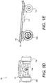
- FIGs. 1A-1E illustrate an exemplary transportation device 100, consistent with embodiments of the present disclosure.
- FIGs. 1A, 1B, 1C , 1D, and 1E provide, respectively, a perspective view, a top view, a bottom view, a front view, and a side view of transportation device 100.
- Transportation device 100 may be configured as a skateboard and include a plurality of wheels, e.g., a front pair of wheels comprising a left front wheel 110a and a right front wheel 110b, and a rear pair of wheels comprising a left rear wheel 120a and a left rear wheel 120b.
- At least one of the plurality of wheels can be an electric motorized wheel, such as a hub-motor driven wheels, a gear-motor driven wheel, a belt-motor driven wheels, etc.
- left front wheel 110a and right front wheel 110b may be driven by a left-side electric motor and a right-side electric motor respectively.
- left rear wheel 120a and right rear wheel 120b can also be driven by, respectively, a left-side electric motor and a right-side electric motor.
- a pair of front wheels (and/or a pair of rear wheels) can be driven by a single motor via a gearbox, which can be configured to drive each of the pair of wheels at a predetermined rotational speed, and can also be configured to drive the wheels at different rotational speeds.
- Transportation device 100 may further include a deck 130 that provides a top surface for supporting a user.
- a force sensor module 140 is placed on or beneath the top surface of deck 130.
- force sensor module 140 may be placed on the top surface of deck 130 to directly bear the force, while in some other embodiments, some protective layers or devices may be attached onto the force sensor module 140 to protect force sensor module 140 from external damage, such as puncture.
- force sensor module 140 may also be installed within the deck 130 for more effective protection, or be installed at the bottom of the deck 130 to simplify the electrical connection and avoid perforations through the deck 130.
- Force sensor module 140 may include one or more force sensors configured to detect a force received at predetermined locations of the top surface. For example, as shown in FIG.
- force sensor module 140 may be distributed across a deck portion 130a, a deck portion 130b, a deck portion 130c, a deck portion 130d, and a deck portion 130e.
- force sensor module 140 may be a thin layer of electric force sensing units with force sensing resistance or force sensing electric capacity.
- the force sensing units may include, for example, Piezoelectric Thin Film sensors made of polyvinylidene fluoride (PVDF), strain gauge, mechanical pressure sensor, or any other force sensor.
- transportation device 100 can be controlled based on a distribution of forces (e.g., exerted by a weight of the user) received by portions of force sensor module 140 that correspond to the deck portions 130a-130e, and the distribution of forces can vary based on a posture of the user (e.g., standing straight, leaning forward, leaning backward, leaning left, leaning right, etc.). As a result, the user can interact with the top surface to control a movement of transportation device 100.
- a distribution of forces e.g., exerted by a weight of the user
- portions of force sensor module 140 that correspond to the deck portions 130a-130e
- the distribution of forces can vary based on a posture of the user (e.g., standing straight, leaning forward, leaning backward, leaning left, leaning right, etc.).
- a posture of the user e.g., standing straight, leaning forward, leaning backward, leaning left, leaning right, etc
- deck 130 also includes a bottom surface, on which a pair of trucks 150a and 150b is mounted.
- Truck 150a is configured to attach left front wheel 110a and right front wheel 110b to the bottom surface
- truck 150b is configured to attach left rear wheel 120a and right rear wheel 120b to the bottom surface.
- At least one of trucks 150a and 150b is also rotatable to provide steering to transportation device 100.
- the steering of transportation device 100 can be further facilitated by introducing a difference in the rotation speeds between at least one of the front pair of wheels and at least one of the rear pair of wheels, or a difference in the rotation speeds between at least one of the left pair of wheels and at least one of the right pair of wheels.
- left front wheel 110a and right front wheel 110b are driven by a left-side electric motor and a right-side electric motor respectively
- the left-side electric motor and the right-side electric motor can be controlled to rotate at different rotational speeds, to facilitate the steering of transportation device 100 (e.g., by reducing a turning radius).
- a method of controlling a transportation device 100 further includes a controller 160.
- Controller 160 may be mounted on the bottom surface of deck 130 (as shown in FIG. 1C ), or may be placed anywhere on or within deck 130, and may be configured to control a rotation direction and a rotation speed of the one or more motors that drive the plurality of wheels.
- Controller 160 may include one or more known processing devices.
- the processor may be from the family of processors manufactured by Intel, from the family of processors manufactured by Advanced Micro Devices, or the like. Alternatively, the processor may be based on the ARM architecture.
- controller 160 can also include an application-specific integrated circuit (ASIC), a field programmable gate array (FPGA), etc. Controller 160 can be programmed to perform one or more methods consistent with embodiments of the present disclosure.
- ASIC application-specific integrated circuit
- FPGA field programmable gate array
- controller 160 is configured to determine a target direction (e.g., forward, backward, left, or right) and a target speed of movement of transportation device 100, and control the one or more motors to achieve the target direction and the target speed of movement.
- Controller 160 can receive information, from force sensor module 140, about the magnitudes of forces received at a plurality of predetermined locations on the top surface of deck 130. Controller 160 can then determine a distribution of forces based on the information. Based on the distribution of forces and an operation state of transportation device 100, controller 160 can determine a target speed and a target direction of movement of transportation device 100.
- transportation device 100 may determine, based on the distribution of forces, whether the user is standing stably, for a predetermined amount of time (e.g., five seconds). If controller 160 determines that the user is standing stably for at least the predetermined amount of time, which may indicate that the user is standing upright, controller 160 (and transportation device 100) may enter an initialization state, in which it determines a reference distribution based on the distribution of forces, and then enter a motion state.
- the reference distribution can be used for detecting changes in the distribution of forces, and the degrees of the changes, which can indicate a posture change of the user.
- Controller 160 can interpret the posture change as a signal to adjust a movement of transportation device 100 and, based on a relationship between the reference distribution and the updated distribution of forces, adjust a magnitude of the signal.
- the detection of a user's signal to adjust the movement of transportation device 100 can be customized to take into account the different weights of different users, as well as their different standing postures. This enables more accurate detection of the user's signals to adjust the movement of the transportation device, therefore the system can become more robust.
- controller 160 can detect, based on information provided from force sensor module 140, whether there is a change in the distribution of the forces which, as discussed above, may indicate a change in the posture. Based on a relationship between the updated distribution of the forces and the reference distribution, controller 160 can then determine a target speed and a target direction of movement of transportation device 100. As an illustrative example, controller 160 may detect that a force detected at front deck portion 130a is larger than the forces detected at other sensor portions, and determine that transportation device 100 is to move forward (as indicated by direction A). Moreover, controller 160 can also determine a target speed of transportation device 100 based on the magnitudes of forces detected at each of deck portions 130a, 130b, 130c, and 130d, and the reference distribution.
- controller 160 can also set the target speed to zero after determining, based on the information from force sensor module 140, that the total forces received by the top surface of deck 130, at any given time, is lower than a threshold.
- a threshold can indicate, for example, that the user has fallen off (or in the middle of falling off) transportation device 100 and is not in control of it.
- the threshold can be preset to an initial value when transportation device 100 is in the stationary state, and can be updated based on the reference distribution (e.g., to reflect the user's weight) when transportation device 100 is in the motion state. With such an arrangement, the risk of transportation device 100 hitting a person nearby, when the device is not under a user's control, can be mitigated.
- controller 160 can then control a rotation direction and a rotation speed of the one or more motors to achieve the target speed and the target direction. For example, as discussed above, controller 160 can transmit signals to a left-side electric motor that drives left front wheel 110a, and to a right-side electric motor that drives right front wheel 110b, to introduce a rotation speed difference between the front pair of wheels, in order to steer transportation device 100 to move along the target direction. Moreover, controller 160 can also transmit signals to both the left-side electric motor and the right-side electric motor to control the motors to rotate at a certain rotation speed, to achieve the target speed.
- controller 160 can also be a part of a feedback system that controls the target speed and the target direction.
- transportation device 100 may include a motor speed sensor that detects a rotation speed of the electric motors. Based on a difference between the rotational speed of the electric motors and a target rotational speed (which can be determined based on the target speed of movement of transportation device 100), controller 160 can then adjust the signals provided to the electric motors to introduce an acceleration (or deceleration) to achieve the target speed.
- the acceleration (or deceleration) can be set based on a predetermined responsiveness of the system, which can be set according to different operation states of transportation device 100 and for different purposes.
- controller 160 determines to set the target speed to zero in response to an indication that the user has fallen off (or in the middle of falling off) transportation device 100 (e.g., based on a determination that the total forces received by the top surface is below a threshold), it can control the rotational speed of the motors to zero within a predetermined amount of time (e.g., one second), to further mitigate the risk of transportation device 100 hitting another person while moving out of control.
- a predetermined amount of time e.g., one second
- transportation device 100 may include an orientation sensor (e.g., an inertial measurement unit (IMU)) attached to the top or bottom surface of or placed within deck 130 and configured to detect a current turning angle and/or a current turning speed of deck 130. Controller 160 can then adjust the signals provided to the left-side electric motor and the right-side electric motor (e.g., for introducing a differential rotational speed) based on a difference between the target direction and a current direction of movement of transportation device 100.
- IMU inertial measurement unit
- the IMU may provide information about a pitch angle of transportation device 100 that may indicate, for example, the transportation device is going uphill or downhill.
- controller 160 may also adjust the signals provided to the left-side electric motor and the right-side electric motor accordingly. For example, if the pitch angle indicates that transportation device 100 is going uphill, controller 160 may increase the torques of both of the left-side electric motor and the right-side electric motor to provide more assistance for the uphill movement. Also, if the pitch angle indicates that transportation device 100 is going downhill, controller 160 may decrease the torques of both of the left-side electric motor and the right-side electric motor (or cause the motor to generate reverse braking torque) to reduce the speed.
- transportation device 100 may be able to adjust the motor torque according to the pitch angle when the pitch angle is within a range of +15 degrees with respect to the horizon.
- controller 160 may also receive signals from a remote control (not shown in FIGS. 1A-1E ), and control an operation state (and/or a target speed and a target direction of movement) of transportation device 100.
- controller 160 may receive a signal from a remote control to maintain transportation device 100 in the stationary state, for security purpose.
- Controller 160 may also receive a signal from a remote control to set a target speed and a target direction of movement of transportation device 100 as a backup (e.g., when force sensor module 140 fails).
- FIG. 2 is a cross-section view of an exemplary left front wheel 110a driven by a hub motor, consistent with embodiments of the present disclosure.
- the exemplary hub-motor driven wheel includes an axis 111, bearings 112 and 113, an inner stator 114 coupled to axis 111, an outer rotor 115 coupled to axis 111 via bearings 112 and 113, and a damping tire 116 directly attached to outer rotor 115.
- the exemplary hub-motor driven left front wheel 110a combines a motor (e.g., stator 114 and rotor 115) and tire 116 together, such that tire 116 is directly attached to the outer rotor, unlike conventional motorized wheels using an outer rotor to drive a metal case to which a tire is attached.
- a motor e.g., stator 114 and rotor 115
- tire 116 is directly attached to the outer rotor, unlike conventional motorized wheels using an outer rotor to drive a metal case to which a tire is attached.
- damping tire 116 includes an elastic material absorbing vibration to protect outer rotor 115, inner stator 114, and other components of the wheel. It may also include an abradable material reducing wear when touching the ground.
- damping tire 116 includes an inner layer and an outer layer (not shown in FIG. 2 ).
- the outer layer is made of a material with low elasticity and high abradability when touching the ground.
- the inner layer functions as a damping part, made of a material with high elasticity absorbing vibration to protect the outer rotor, inner rotor, and other components of the wheel.
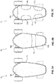
- FIGs. 3A-3C illustrate various examples of force sensor module 140, consistent with embodiments of the present disclosure.
- force sensor module 140 may include a single force sensor region extending across the top surface of deck 130.
- force sensor module 140 may include a front force sensor region 140a and a rear force sensor region 140b.
- Front force sensor region 140a may extend across a front section of deck 130 (which includes, for example, front deck portion 130a)
- rear force sensor region 140b may extend across a rear section of deck 130 (which includes, for example, rear deck portion 130b).
- FIG. 3A-3C illustrate various examples of force sensor module 140, consistent with embodiments of the present disclosure.
- FIG. 3A force sensor module 140 may include a single force sensor region extending across the top surface of deck 130.
- force sensor module 140 may include a front force sensor region 140a and a rear force sensor region 140b.
- Front force sensor region 140a may extend across a front section of deck 130 (which includes, for example, front deck portion 130a)
- force sensor module 140 may also include more than two force sensor regions, including a front force sensor region 140c, a left front force sensor region 140d, a right front force sensor region 140e, a left rear force sensor region 140f, and a right rear force sensor region 140g. Each of these force sensor regions may comprise one or more force sensing units described above.
- FIGs. 4A-4C illustrate exemplary configurations for detecting a distribution of forces with the exemplary force sensors illustrated in FIGS. 3A-3C , consistent with embodiments of the present disclosure.
- diagram 402 illustrates one possible set of locations of foot regions 300a and 300b of a user standing on the top surface of deck 130, which is covered with a single force sensor module 140 as shown in FIG. 3A .
- diagram 404 illustrates another possible set of locations of foot regions 300a and 300b.
- Sensor module 140 can detect a first force in a region 310a and a second force in a region 310b of foot region 300a.
- Force sensor module 140 can also detect a third force in a region 320a and a fourth force in a region 320b of foot region 300b. Force sensor module 140 can then provide information about the first, second, third, and fourth forces, and their associated regions (regions 310a, 310b, 320a, and 320b) in force sensor module 140, to controller 160, which can then determine a distribution of forces accordingly. For example, based on a distribution of force generated according to the set of locations of foot regions 300a and 300b of diagram 402, controller 160 may determine to steer transportation device 100 towards direction C. Further, based on a distribution of force generated according to the set of locations of foot regions 300a and 300b of diagram 404, controller 160 may determine to steer transportation device 100 towards direction D.
- FIG. 4B illustrates that foot regions 300a and 300b that partially overlap with, respectively, front force sensor region 140a and rear force sensor region 140b of FIG. 3B .
- diagram 412 illustrates one possible set of locations of foot regions 300a and 300b on front sensor region 140a and rear sensor region 140b
- diagram 414 illustrates another possible set of locations of foot regions 300a and 300b on front force sensor region 140a and rear force sensor region 140b.
- Controller 160 may then determine a distribution of force by associating the measured forces with each of the sensor regions, and with the locations of the measured force within each sensor region.
- controller 160 may determine to steer transportation device 100 towards, for example, directions A, B, C, D, or anywhere in between (e.g., between directions A and B). Further, based on a distribution of force generated according to the set of locations of foot regions 300a and 300b of diagram 414, controller 160 may determine to steer transportation device 100 towards direction B.
- diagram 422 of FIG. 4C illustrates that region 310a and region 310b of foot region 300a overlap with, respectively, front force sensor region 140c and right front force sensor region 140e of FIG. 3C , while region 320a and region 320b of foot region 300b overlap with, respectively, left rear force sensor region 140c and right rear force sensor region 140e of FIG. 3C .
- diagram 424 of FIG. 4C illustrates that region 310a and region 310b of foot region 300a overlap with, respectively, front force sensor region 140c and left front force sensor region 140d of FIG.
- Controller 160 may then determine a distribution of force by associating the measured forces with each of the sensor regions. Based on a distribution of force generated according to the set of locations of foot regions 300a and 300b of diagram 422, controller 160 may determine to steer transportation device 100 towards direction C. Further, based on a distribution of force generated according to the set of locations of foot regions 300a and 300b of diagram 424, controller 160 may determine to steer transportation device 100 towards direction D.
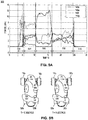
- FIGs. 5A and 5B illustrate examples of variations of force distribution, which can be used for determining a target speed and a target direction using exemplary configurations consistent with embodiments of the present disclosure.
- the variations are illustrated using the example of force sensor module 140 including force sensor regions 140c-g as illustrated in FIG. 3C , it is understood that the method can also be used in conjunction with the examples of force sensor module 140 of FIG. 3A and FIG. 3B .
- chart 500 illustrates a variation of forces detected by force sensor regions 140c, 140e, 140f, and 140g with respect to time.
- force sensor region 140c measures a force of 35N (Newton)
- force sensor region 140d measures a force of 0N
- force sensor region 140e measures a force of 80N
- force sensor region 140f measures a force of 40N
- force sensor region 140g measures a force of 5N.
- force sensor region 140c measures a force of 110N
- force sensor region 140d measures a force of 0N
- force sensor region 140e measures a force of 40N
- force sensor region 140f measures a force of 10N
- force sensor region 140g measures a force of 0N.
- controller 160 can determine an operation state of transportation device 100. For example, referring to FIG. 5A , during time interval 502 when transportation device 100 is in an initialization state and the user steps onto the device, the forces detected by force sensor module 140 may experience a relatively huge variation with respect to time. Controller 160 can determine that there is a relatively huge variation of the forces with rest to time by, for example, determining a variance value for the samples of detected force received up to the current time, and compare the variance value against a variance threshold. If the variance value exceeds the variance threshold, controller 160 may determine that the transportation device 100 is to remain in the stationary state as the user is still adjusting his or her standing posture on the device.
- controller 160 may determine that the variance value for the samples of detected force is below the variance threshold. Based on this determination, controller may determine, based on the current distribution of forces, a reference distribution of forces.
- the reference distribution of forces can act as an indicator that the user is standing upright on the transportation device. Controller 160 may interpret such a standing posture as a signal that transportation device is to maintain its current state (e.g., stationary state, or a motion state with a fixed direction and speed of motion). Controller 160 can then use the reference distribution of forces as a reference to determine a change in the direction and/or speed of motion, after detecting changes in the distribution of force.
- controller 160 may determine the reference distribution of forces by calculating a force reference for the front deck portion ( S front ), a force reference for the rear deck portion ( S rear ), a force reference for the left deck portion ( S left ), and a force reference for the right deck portion ( S right ).
- force sensor regions 140c-g obtain a reading of 35N for S 0 , a reading of 0N for S 1 , a reading of 80N for S 2 , a reading of 40N for S 3 , and a reading of 5N for S 4 .
- a reference distribution can be determined as follows: Table 1 S front S rear S left S right 72% 28% 36% 64%
- Table 1 illustrates a reference distribution, which can be associated with an indication that the user is standing stably and upright on transportation device 100. Controller 160 can then detect, based on a relationship between the reference distribution and a current distribution of forces, whether there is a posture change of the user, the change of speed and direction of motion signaled by the posture change, and the degree of change, as to be discussed below.
- controller 160 before entering the motion state, controller 160 also compares a sum of the forces S sum against a predetermined initial threshold.
- the sum of the forces S sum typically reflects the weight of the user. If controller 160 determines that S sum is below a predetermined initial threshold, controller 160 may determine that the user has fallen off (or in the middle of falling off) the transportation device, and is no longer in control of it. In that case, controller 160 may maintain the transportation device in the stationary state, or if the transportation device is in the motion state, bring the transportation device to stop (by setting the target speed as zero).
- controller 160 may update the threshold based on S sum (e.g., by setting the threshold to be equal to half of S sum ), and continue to monitor the sum of forces detected by force sensor regions 140c-140g. For example, referring back to FIG. 5A , during interval 510 controller 160 may determine that a sum of current forces falls the updated threshold, and bring the transportation device to stop.
- controller 160 may determine a change in the distribution of force, and the degree of change, based on the forces detected by force sensor regions 140c-g and the reference distribution. Based on the change, controller 160 may determine an indication from the user for a change in the movement of the transportation device. Controller 160 can then determine an updated speed and/or an updated direction of movement of the transportation device, based on the indication.
- K forward and K left can be a scaling factor with a typical value of 5.
- Controller 160 may determine an indication of direction of movement based on d forward and d left . For example, if d forward exceeds zero, controller 160 may determine that the user signals the transportation device to move forward, and if d forward is below zero, that the user signals the transportation device to move backward. Also, if d left exceeds zero, controller 160 may determine that the user signals the transportation device to move left, and if d left is below zero, that the user signals the transportation device to move to the right. Further, if both d forward and d left are zero, controller 160 may determine that user signals the transportation device to maintain its current direction and speed of movement.
- the parameters d forward and d left may represent a tiling angle of the user with respect to the horizon.
- the values of d forward and d left can be related to a force exerted by the person along a direction of acceleration. Based on the magnitude and direction (indicated by whether the value exceeds zero) of d forward and d left , controller 160 can determine a target speed and a target direction of movement of transportation device 100.
- force sensor regions 140c, 140d, 140e, 140f, and 140g obtain the values of P 0 , P 1 , P 2 , P 3 , and P 4 as, respectively, 110N, 0N, 40N, 10N, and 0N.
- controller 160 may obtain a value of 5.46° for d forward , and a value of -1.03° for d left . Based on the values d forward and d left , controller 160 may determine that the user signals the transportation device to move along a direction between forward and right.
- Controller 160 can continue receiving updated force measurement data from force sensor regions 140c-g and update the values of d forward and d left . For example, for interval 508, controller 160 may obtain an updated values for d forward and d left and, based on the updated values, determine that the user signals the transportation device to move backward.
- controller 160 may also determine a sum of the forces, and compare the sum against a threshold to determine whether the user has fallen off (or in the middle of falling off) the transportation device. For example, referring back to FIG. 5A , at 15 seconds after the reference time point, the sum of force is 160N, while the threshold, as determined during the initialization, can be half of S sum and equals 80N. Based on the determination that the sum of force exceeds the threshold, controller 160 can determine that user is still standing on the transportation device, and can maintain the motion state of the transportation device.
- the determination of the angle of tilting left ( d left ) can take into account a rolling angle of deck 130.
- deck 130 may tilt towards the turning direction. The tilting may occur due to uneven force exerted on the left and right edges of the deck, and can increase the magnitude of d left .
- the actual tilting angle will be larger than d left determined based on the force distribution.
- transportation device 100 is turning right, the actual tilting angle will be smaller than d left determined based on the force distribution (i.e., it becomes more negative).
- the rolling angle can be measured by the IMU attached on the bottom surface (or on the top surface) of deck 130.
- P roll can be a rolling angle measured by the IMU
- S roll can be a reference rolling angle.
- S roll can be determined during the initialization state when the reference distribution was determined, which can also correspond to a state when transportation device 100 is moving in a straight line and is not turning.
- the parameter ⁇ can be any value within the range of 0 to 1, and can be determined based on the characteristics of the IMU.
- the value of ⁇ can be, for example, 0.5.
- controller 160 can then determine a value of an acceleration.
- the value of d forward can indicate a tilting angle of the body of the user towards a forward direction (e.g., along direction A of FIG. 1B ).
- the forward acceleration can be proportional to the degree of tilting forward, with K acc being a scaling factor, and d forward is the angle of forward tiling in radians.
- K acc is a scaling factor
- d forward is the angle of forward tiling in radians.
- a typical value of K acc can be 10.
- T is a period during which deck 130 experiences the force distribution that leads to a certain value of d forward and a forward.
- the value of d left ′ can indicate a tilting angle of the body of the user towards left (or right, if d left ′ is negative).
- the centripetal acceleration is related to, for example, a distance between the front (or back) wheel pairs that provide the steering ( W ), and a difference in the linear speed between the wheel pair ( ⁇ V ).
- the difference in the linear speed ( ⁇ V ) can be proportional to the degree of tilting left (or right), with K dif being a scaling factor.
- K dif may be related to a distance between the front (or back) pairs (W) that provide the steering.
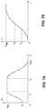
- controller 160 may also impose a limit on the acceleration based on a current speed of transportation device 100, and a prior state of operation. For example, referring to FIGs. 7A and 7B , if transportation device 100 just transits from the stationary state (i.e., having a zero speed) to the motion state, controller 160 may impose a limit of a 0 on the maximum acceleration that can be caused by the distribution of force (and the associated values of d forward and d left ′ ). As the speed of transportation device 100 increases, the acceleration limit can also increases, until it tops out at a value of a max .
- the acceleration limit may decrease, until to a point where the speed of the transportation device reaches the maximum speed v max , at which point the acceleration limit can become zero. In that case, no further increase in the speed will be permitted. With such an arrangement, the safety of operation of transportation device 100 can be improved.
- transportation device 100 may include a feedback system, which includes controller 160, to control the speed and direction of movement based on the target speed and target direction. For example, after determining the target forward/backward speed V target , controller 160 may determine a number of discrete steps of increasing (or decreasing) the speed, such that the acceleration (or deceleration) within a time interval between the discrete steps does not exceed the acceleration (or deceleration) limit according to FIG. 7A . For each discrete step, controller 160 may determine an intermediate target speed, and then generate a motor driving signal to the motor, to cause the motor to achieve the intermediate target speed.
- controller 160 may determine a number of discrete steps of increasing (or decreasing) the speed, such that the acceleration (or deceleration) within a time interval between the discrete steps does not exceed the acceleration (or deceleration) limit according to FIG. 7A .
- controller 160 may determine an intermediate target speed, and then generate a motor driving signal to the motor, to cause the motor to achieve the intermediate target speed.
- Controller 160 may also receive information from one or more motor sensors configured to measure a rotation speed of the motor, and determine a magnitude of the signal based on a difference between the intermediate target speed and a current linear speed (obtained based on the rotation speed) of the motor.
- controller 160 may also implement a proportional-integral-derivative (PID) controller to generate the motor driving signal based on the difference between the intermediate target speed and the current linear speed.
- PID proportional-integral-derivative
- transportation device 100 may also determine, based on the information from the IMU, a turning angle and/or a turning rate of transportation device 100, and control the signals transmitted to the motors that drive the steering wheel pair, based on a difference between the turning angle (and/or turning rate) and the target direction (as determined from d forward and d left ′ ). Further, as discussed above, transportation device 100 may determine a pitch angle that indicates the device is going uphill or downhill, and control the signals transmitted to the motors to change their torques accordingly (e.g., increasing the torque for uphill movement, reducing the torque or introducing a reverse torque for downhill movement, etc.)
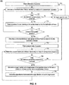
- FIG. 8 illustrates a sequence of steps that performs an exemplary process 800 for controlling a transportation device, according to embodiments of the present disclosure.
- the process of FIG. 8 may be implemented in software, hardware, or any combination thereof.
- the process 800 will be described in the context of transportation device 100, such that the disclosed process may be performed by software executing in controller 160.
- controller 160 enters a first state of operation.
- the first state of operation can be, for example, an initialization state, in which transportation device 100 is stationary. This can happen when transportation device 100 is just started up, or just came to a stop.
- controller 160 determines a first distribution of forces received by the top surface of transportation device 100.
- the first distribution of forces can be determined based on information provided by force sensor regions 140c-g.
- controller 160 determines whether the total force exceeds a predetermined force threshold, to detect whether the user has fallen off (or in the middle of falling off) the transportation device. If controller 160 determines that the total force does not exceed the predetermined force threshold, controller 160 may proceed to step 708 and set the target speed of transportation device 100 to zero, to bring it to a stop. Afterwards, controller 160 may proceed back to step 702 and enter (or maintain) the first state of operation.
- controller 160 can proceed to step 710 to detect a posture of a user standing on the surface based on the first distribution of forces.
- the detection may include determining whether the force distribution data indicates a predetermined posture, such as a stable standing posture. The determination can be based on, for example, a variance value of samples of the forces received up to a current time point. If controller 160 determines, in step 712, that a stable standing posture is not detected (e.g., because the variance value exceeds a variance threshold, which may indicate that the user is still adjusting his or her posture, or is just getting up the transportation device, etc.), controller 160 may proceed back to 704 to acquire an updated set of forces.
- controller 160 may proceed to step 714 to determine a reference distribution and update the force threshold based on the first distribution of forces.
- the determination of reference distribution can be based on, for example, Expressions 1-5 as discussed above.
- the force threshold can also be updated as, for example, half of the total of the first distribution of forces.
- controller 160 can proceed to step 716 and enter a second state of operation.
- the second state of operation may be, for example, the motion state, in which controller 160 can control a direction and a speed of movement of transportation device 100.
- controller 160 can proceed to step 718 to determine a second distribution of forces received by the top surface of transportation device 100.
- the second distribution of forces can be determined based on information provided by force sensor regions, e.g., 140c-140g.
- controller 160 can proceed to step 720 to determine whether the total of the second distribution of forces exceed the updated force threshold. If the total does not exceed the updated force threshold, which may indicate the user has fallen off (or in the middle of falling off) the transportation device, controller 160 may proceed to step 708 to set the target speed to zero, and proceed back to step 702 to reenter the first state of operation If the total exceeds the updated force threshold, controller 160 can proceed to step 722 to determine a target direction and a target speed of transportation device 100 based on the second distribution of forces, and the reference distribution, based on Expressions 6-19 as stated above. For example, controller 160 may determine a linear acceleration and a target linear speed for a forward/backward movement.
- Controller 160 may also determine a difference in the rotation speed of motors for a steering wheel pair, and determine the target speed for each wheel of the wheel pair based on the difference. In some embodiments, controller 160 may also receive information about a rolling angle of deck 130, and include the rolling angle in the determination of target direction and target speed, based on Expressions 13 and 14 as stated above.
- controller 160 may proceed to step 724 to cause transportation device 100 to move towards the target direction, and at the target speed. For example, controller 160 may determine a number of intermediate steps in changing the linear speed of transportation device 100, such that the acceleration does not exceed a predetermined limit, which can also be correlated to the speed as illustrated in FIGs. 7A and 7B . Controller 160 may also be a part of a feedback loop that monitors a linear speed, and a turning speed and/or turning angle of transportation device 100, and adjusts the signals provided to the motor based on the monitored speed and angle information. Controller 160 may then proceed back to step 718 to receive updated second distribution of forces.
- System 900 may include one or more controller(s) 160 of FIG. 1C , and one or more sensors 930.
- Controller 160 may include one or more processors 920, one or more I/O devices 922, and one or more memories 924.
- system 900 may take the form of a mobile computing device, general-purpose computer, etc., for performing one or more operations consistent with the disclosed embodiments.
- Processor 920 may include one or more known processing devices.
- the processor may be from the family of processors manufactured by Intel, from the family of processors manufactured by Advanced Micro Devices, or the like.
- the processor may be based on the ARM architecture.
- the processor may be a mobile processor. The disclosed embodiments are not limited to any type of processor configured in controller 160.
- I/O devices 922 may be one or more devices configured to allow data to be received and/or transmitted by controller 160.
- the I/O devices 922 may include one or more communication devices and interfaces, and any necessary analog-to-digital and digital-to-analog converters, to communicate with and/or control other mechanical components and devices, such as sensors 930 and one or more motors (not shown in FIG. 9 ).
- Memory 924 may include one or more storage devices configured to store software instructions used by the processor 920 to perform functions related to the disclosed embodiments.
- the memory 924 may be configured to store software instructions, such as program(s) 926, that perform one or more operations when executed by the processor(s) 920.
- memory 924 may include a single program 926, such as a user-level application, that performs the functions of the disclosed embodiments, or may comprise multiple software programs.
- the processor 920 may execute one or more programs (or portions thereof) remotely located from controller 160.
- memory 924 also may be configured to store data, for example, for use by the software program(s) 926.
- Sensors 930 may include, for example, force sensors, motor speed sensors, IMU, etc.
- systems 900 can be configured as transportation device 100, and software program(s) 926 can include one or more software modules that, when executed by controller 160, perform a method of controlling transportation device 100 based on a distribution of forces received by deck 130 and detected by sensors 930.
- the method may include, for examples, process 800 of FIG. 8 .
Landscapes
- Engineering & Computer Science (AREA)
- Mechanical Engineering (AREA)
- Physics & Mathematics (AREA)
- Transportation (AREA)
- General Physics & Mathematics (AREA)
- Combustion & Propulsion (AREA)
- Aviation & Aerospace Engineering (AREA)
- Radar, Positioning & Navigation (AREA)
- Remote Sensing (AREA)
- Chemical & Material Sciences (AREA)
- Automation & Control Theory (AREA)
- Power Engineering (AREA)
- Mathematical Physics (AREA)
- Computing Systems (AREA)
- Theoretical Computer Science (AREA)
- Motorcycle And Bicycle Frame (AREA)
- Handcart (AREA)
- Electric Propulsion And Braking For Vehicles (AREA)
- Selective Calling Equipment (AREA)
- Rehabilitation Tools (AREA)
- Toys (AREA)
Description
- The present disclosure relates to a transportation device, and more particularly, to a self-propelled personal transportation device.
- Personal transportation devices, such as skateboards, roller skates, bicycle, etc., enhance the mobility of people by providing an alternative mode of transportation. Self-propelled personal transportation devices, such as electric skateboards, can transport a person over an extended range and at a relatively high speed, thereby further enhancing the mobility of people.
- Although self-propelled personal transportation devices can enhance the mobility of people, they can pose safety problems to the user and to other people. For example, if the device is not operated properly, the user may fall from the device when the device is moving at a high speed. The device may also collide with other people at a high speed. In both cases, an injury may occur.
- Conventional self-propelled personal transportation devices, such as electric skateboards, may be controlled by a remote control. However, this may require the user to interact with two devices at the same time (e.g., the remote control and the electric skateboard), which makes the operation non-intuitive and error-prone.
- Therefore, there is a need to provide an effective, and intuitive, means for operating a self-propelled personal transportation device. The document
WO2011/098935 discloses such a self propelled personal transportation device according to the preamble ofclaims 1 and 8. - The embodiments of the present disclosure provide a system and a method for controlling a transportation device. Advantageously, the exemplary embodiments provide for robust, flexible, intuitive, and easy operation of a transportation device by detecting a distribution of force exerted by a user, and adjusting at least one of a speed and a direction of the transportation device based on the distribution of force.
- In one aspect, the present disclosure is directed to a transportation apparatus. The apparatus comprises: a surface to receive a plurality of forces at a plurality of locations thereon; a plurality of force sensors, placed on or beneath the surface, to provide information related to the plurality of forces; a plurality of wheels beneath the surface, at least one of the plurality of wheels being coupled with a motor; and a controller to: determine, based on the provided information, a first plurality of forces at the plurality of locations; determine, based on the first plurality of forces, a reference distribution associated with the plurality of locations; determine, based on the provided information, a second plurality of forces; determine a target speed of the apparatus based on the reference distribution and the second plurality of forces; and provide one or more first signals to the motors to cause the apparatus to move at the target speed and where the controller also determines target turning direction and provide one or more second signals to the motors based on the target turning direction.
- In another aspect, the present disclosure is directed to a computer-implemented method for controlling a transportation device. The method comprises: receiving, from a plurality of force sensors placed on or beneath a surface of the transportation device, information about a first plurality of forces at a plurality of locations; determining via a controller, based on the first plurality of forces, a reference distribution, wherein the reference distribution is associated with the plurality of locations; receiving, from the plurality of force sensors, information about a second plurality of forces at a plurality of locations; determining, via the controller, a target speed of the transportation device based on the reference distribution and the second plurality of forces; and providing, via on the controller, one or more first signals to one or more motors of the transportation device to cause the transportation device to move at the target speed and the method further comprises determining a target turning direction and providing one or more second signals to the motors based on the target turning direction.
- Additional features and advantages of the disclosed embodiments will be set forth in part in the description that follows, and in part will be obvious from the description, or may be learned by practice of the disclosed embodiments. The features and advantages of the disclosed embodiments will be realized and attained by the elements and combinations particularly pointed out in the appended claims.
- It is to be understood that both the foregoing general description and the following detailed description are examples and explanatory only and are not restrictive of the disclosed embodiments as claimed.
- The accompanying drawings, which are incorporated in and constitute a part of this specification, illustrate exemplary embodiments of the present disclosure, and together with the description, serve to explain the principles of the disclosure.
-
FIGs. 1A-1E are schematic diagrams of an exemplary transportation device, consistent with embodiments of the present disclosure. -
FIG. 2 illustrates a cross-section of an exemplary electric motorized wheel, consistent with embodiments of the present disclosure. -
FIGs. 3A-3C are schematic diagrams of an exemplary force sensor module, consistent with embodiments of the present disclosure. -
FIGs. 4A-3C illustrate examples of detections of force by the exemplary force sensor modules ofFIG. 3A-3C . -
FIGs. 5A-5B illustrate examples of variations of force distribution based on which a target speed and a target direction can be determined using exemplary configurations consistent with embodiments of the present disclosure. -
FIG. 6 illustrates an exemplary turning operation of an exemplary transportation device, consistent with embodiments of the present disclosure. -
FIGs. 7A-7B illustrate exemplary methods of setting an acceleration limit, consistent with embodiments of the present disclosure. -
FIG. 8 is a flowchart of an exemplary method for controlling a transportation device, according to embodiments of the present disclosure. -
FIG. 9 is a block diagram of an exemplary system for controlling a transportation device, according to embodiments of the present disclosure. - The embodiments of the present disclosure provide a system and a method for controlling a transportation device. Embodiments of the present disclosure provide a system that enables a user to control a transportation device by varying a distribution of forces exerted on the device with, for example, a certain posture. The system may adapt the system to a specific posture of a user by determining a reference distribution based on that specific posture. With such an arrangement, the controlling of the transportation device can become more robust, and both the performance and safety of operation can be improved as well.
- Reference will now be made in detail to embodiments and aspects of the present disclosure, examples of which are illustrated in the accompanying drawings. Where convenient, the same reference numbers will be used throughout the drawings to refer to the same or like parts.
-
FIGs. 1A-1E illustrate anexemplary transportation device 100, consistent with embodiments of the present disclosure.FIGs. 1A, 1B, 1C ,1D, and 1E provide, respectively, a perspective view, a top view, a bottom view, a front view, and a side view oftransportation device 100.Transportation device 100 may be configured as a skateboard and include a plurality of wheels, e.g., a front pair of wheels comprising aleft front wheel 110a and a rightfront wheel 110b, and a rear pair of wheels comprising a leftrear wheel 120a and a leftrear wheel 120b. At least one of the plurality of wheels can be an electric motorized wheel, such as a hub-motor driven wheels, a gear-motor driven wheel, a belt-motor driven wheels, etc. As an illustrative example, leftfront wheel 110a and rightfront wheel 110b may be driven by a left-side electric motor and a right-side electric motor respectively. In some embodiments, leftrear wheel 120a and rightrear wheel 120b can also be driven by, respectively, a left-side electric motor and a right-side electric motor. In some embodiments, a pair of front wheels (and/or a pair of rear wheels) can be driven by a single motor via a gearbox, which can be configured to drive each of the pair of wheels at a predetermined rotational speed, and can also be configured to drive the wheels at different rotational speeds. -
Transportation device 100 may further include adeck 130 that provides a top surface for supporting a user. Aforce sensor module 140 is placed on or beneath the top surface ofdeck 130. In some embodiments,force sensor module 140 may be placed on the top surface ofdeck 130 to directly bear the force, while in some other embodiments, some protective layers or devices may be attached onto theforce sensor module 140 to protectforce sensor module 140 from external damage, such as puncture. Moreover,force sensor module 140 may also be installed within thedeck 130 for more effective protection, or be installed at the bottom of thedeck 130 to simplify the electrical connection and avoid perforations through thedeck 130.Force sensor module 140 may include one or more force sensors configured to detect a force received at predetermined locations of the top surface. For example, as shown inFIG. 1B ,force sensor module 140 may be distributed across adeck portion 130a, adeck portion 130b, adeck portion 130c, adeck portion 130d, and adeck portion 130e. In some embodiments,force sensor module 140 may be a thin layer of electric force sensing units with force sensing resistance or force sensing electric capacity. The force sensing units may include, for example, Piezoelectric Thin Film sensors made of polyvinylidene fluoride (PVDF), strain gauge, mechanical pressure sensor, or any other force sensor. As to be discussed in more detail below, with such an arrangement,transportation device 100 can be controlled based on a distribution of forces (e.g., exerted by a weight of the user) received by portions offorce sensor module 140 that correspond to thedeck portions 130a-130e, and the distribution of forces can vary based on a posture of the user (e.g., standing straight, leaning forward, leaning backward, leaning left, leaning right, etc.). As a result, the user can interact with the top surface to control a movement oftransportation device 100. - Moreover,
deck 130 also includes a bottom surface, on which a pair oftrucks Truck 150a is configured to attach leftfront wheel 110a and rightfront wheel 110b to the bottom surface, whiletruck 150b is configured to attach leftrear wheel 120a and rightrear wheel 120b to the bottom surface. At least one oftrucks transportation device 100. In some embodiments, the steering oftransportation device 100 can be further facilitated by introducing a difference in the rotation speeds between at least one of the front pair of wheels and at least one of the rear pair of wheels, or a difference in the rotation speeds between at least one of the left pair of wheels and at least one of the right pair of wheels. For example, in a case whereleft front wheel 110a and rightfront wheel 110b are driven by a left-side electric motor and a right-side electric motor respectively, the left-side electric motor and the right-side electric motor can be controlled to rotate at different rotational speeds, to facilitate the steering of transportation device 100 (e.g., by reducing a turning radius). - As shown in
FIG. 1C , a method of controlling atransportation device 100, according to claim 8, further includes acontroller 160.Controller 160 may be mounted on the bottom surface of deck 130 (as shown inFIG. 1C ), or may be placed anywhere on or withindeck 130, and may be configured to control a rotation direction and a rotation speed of the one or more motors that drive the plurality of wheels.Controller 160 may include one or more known processing devices. For example, the processor may be from the family of processors manufactured by Intel, from the family of processors manufactured by Advanced Micro Devices, or the like. Alternatively, the processor may be based on the ARM architecture. Further,controller 160 can also include an application-specific integrated circuit (ASIC), a field programmable gate array (FPGA), etc.Controller 160 can be programmed to perform one or more methods consistent with embodiments of the present disclosure. - In some embodiments,
controller 160 is configured to determine a target direction (e.g., forward, backward, left, or right) and a target speed of movement oftransportation device 100, and control the one or more motors to achieve the target direction and the target speed of movement.Controller 160 can receive information, fromforce sensor module 140, about the magnitudes of forces received at a plurality of predetermined locations on the top surface ofdeck 130.Controller 160 can then determine a distribution of forces based on the information. Based on the distribution of forces and an operation state oftransportation device 100,controller 160 can determine a target speed and a target direction of movement oftransportation device 100. - For example, when
transportation device 100 is in a stationary state (e.g., when the device is just powered up, or have been controlled to stop),transportation device 100 may determine, based on the distribution of forces, whether the user is standing stably, for a predetermined amount of time (e.g., five seconds). Ifcontroller 160 determines that the user is standing stably for at least the predetermined amount of time, which may indicate that the user is standing upright, controller 160 (and transportation device 100) may enter an initialization state, in which it determines a reference distribution based on the distribution of forces, and then enter a motion state. As to be discussed in detail below, the reference distribution can be used for detecting changes in the distribution of forces, and the degrees of the changes, which can indicate a posture change of the user.Controller 160 can interpret the posture change as a signal to adjust a movement oftransportation device 100 and, based on a relationship between the reference distribution and the updated distribution of forces, adjust a magnitude of the signal. With such an arrangement, the detection of a user's signal to adjust the movement oftransportation device 100 can be customized to take into account the different weights of different users, as well as their different standing postures. This enables more accurate detection of the user's signals to adjust the movement of the transportation device, therefore the system can become more robust. - In the motion state,
controller 160 can detect, based on information provided fromforce sensor module 140, whether there is a change in the distribution of the forces which, as discussed above, may indicate a change in the posture. Based on a relationship between the updated distribution of the forces and the reference distribution,controller 160 can then determine a target speed and a target direction of movement oftransportation device 100. As an illustrative example,controller 160 may detect that a force detected atfront deck portion 130a is larger than the forces detected at other sensor portions, and determine thattransportation device 100 is to move forward (as indicated by direction A). Moreover,controller 160 can also determine a target speed oftransportation device 100 based on the magnitudes of forces detected at each ofdeck portions - In some embodiments,
controller 160 can also set the target speed to zero after determining, based on the information fromforce sensor module 140, that the total forces received by the top surface ofdeck 130, at any given time, is lower than a threshold. This can indicate, for example, that the user has fallen off (or in the middle of falling off)transportation device 100 and is not in control of it. The threshold can be preset to an initial value whentransportation device 100 is in the stationary state, and can be updated based on the reference distribution (e.g., to reflect the user's weight) whentransportation device 100 is in the motion state. With such an arrangement, the risk oftransportation device 100 hitting a person nearby, when the device is not under a user's control, can be mitigated. - After setting the target speed and the target direction of movement,
controller 160 can then control a rotation direction and a rotation speed of the one or more motors to achieve the target speed and the target direction. For example, as discussed above,controller 160 can transmit signals to a left-side electric motor that drivesleft front wheel 110a, and to a right-side electric motor that drives rightfront wheel 110b, to introduce a rotation speed difference between the front pair of wheels, in order to steertransportation device 100 to move along the target direction. Moreover,controller 160 can also transmit signals to both the left-side electric motor and the right-side electric motor to control the motors to rotate at a certain rotation speed, to achieve the target speed. - In some embodiments,
controller 160 can also be a part of a feedback system that controls the target speed and the target direction. For example,transportation device 100 may include a motor speed sensor that detects a rotation speed of the electric motors. Based on a difference between the rotational speed of the electric motors and a target rotational speed (which can be determined based on the target speed of movement of transportation device 100),controller 160 can then adjust the signals provided to the electric motors to introduce an acceleration (or deceleration) to achieve the target speed. The acceleration (or deceleration) can be set based on a predetermined responsiveness of the system, which can be set according to different operation states oftransportation device 100 and for different purposes. As an illustrative example, whentransportation device 100 is moving in a relatively high speed, the responsiveness can be increased (e.g., to improve performance), or decreased (e.g., to improve safety). Also, ifcontroller 160 determines to set the target speed to zero in response to an indication that the user has fallen off (or in the middle of falling off) transportation device 100 (e.g., based on a determination that the total forces received by the top surface is below a threshold), it can control the rotational speed of the motors to zero within a predetermined amount of time (e.g., one second), to further mitigate the risk oftransportation device 100 hitting another person while moving out of control. - Further,
transportation device 100 may include an orientation sensor (e.g., an inertial measurement unit (IMU)) attached to the top or bottom surface of or placed withindeck 130 and configured to detect a current turning angle and/or a current turning speed ofdeck 130.Controller 160 can then adjust the signals provided to the left-side electric motor and the right-side electric motor (e.g., for introducing a differential rotational speed) based on a difference between the target direction and a current direction of movement oftransportation device 100. - Moreover, the IMU may provide information about a pitch angle of
transportation device 100 that may indicate, for example, the transportation device is going uphill or downhill. In such a case,controller 160 may also adjust the signals provided to the left-side electric motor and the right-side electric motor accordingly. For example, if the pitch angle indicates thattransportation device 100 is going uphill,controller 160 may increase the torques of both of the left-side electric motor and the right-side electric motor to provide more assistance for the uphill movement. Also, if the pitch angle indicates thattransportation device 100 is going downhill,controller 160 may decrease the torques of both of the left-side electric motor and the right-side electric motor (or cause the motor to generate reverse braking torque) to reduce the speed. In some embodiments,transportation device 100 may be able to adjust the motor torque according to the pitch angle when the pitch angle is within a range of +15 degrees with respect to the horizon. - In some embodiments,
controller 160 may also receive signals from a remote control (not shown inFIGS. 1A-1E ), and control an operation state (and/or a target speed and a target direction of movement) oftransportation device 100. As an illustrative example,controller 160 may receive a signal from a remote control to maintaintransportation device 100 in the stationary state, for security purpose.Controller 160 may also receive a signal from a remote control to set a target speed and a target direction of movement oftransportation device 100 as a backup (e.g., whenforce sensor module 140 fails). -
FIG. 2 is a cross-section view of an exemplary leftfront wheel 110a driven by a hub motor, consistent with embodiments of the present disclosure. The exemplary hub-motor driven wheel includes anaxis 111,bearings inner stator 114 coupled toaxis 111, anouter rotor 115 coupled toaxis 111 viabearings tire 116 directly attached toouter rotor 115. The exemplary hub-motor driven leftfront wheel 110a combines a motor (e.g.,stator 114 and rotor 115) andtire 116 together, such thattire 116 is directly attached to the outer rotor, unlike conventional motorized wheels using an outer rotor to drive a metal case to which a tire is attached. - In some embodiments, damping
tire 116 includes an elastic material absorbing vibration to protectouter rotor 115,inner stator 114, and other components of the wheel. It may also include an abradable material reducing wear when touching the ground. In some embodiments, dampingtire 116 includes an inner layer and an outer layer (not shown inFIG. 2 ). The outer layer is made of a material with low elasticity and high abradability when touching the ground. The inner layer functions as a damping part, made of a material with high elasticity absorbing vibration to protect the outer rotor, inner rotor, and other components of the wheel. -
FIGs. 3A-3C illustrate various examples offorce sensor module 140, consistent with embodiments of the present disclosure. In some embodiments, as shown inFIG. 3A ,force sensor module 140 may include a single force sensor region extending across the top surface ofdeck 130. Also, in some embodiments, as shown inFIG. 3B ,force sensor module 140 may include a frontforce sensor region 140a and a rearforce sensor region 140b. Frontforce sensor region 140a may extend across a front section of deck 130 (which includes, for example,front deck portion 130a), and rearforce sensor region 140b may extend across a rear section of deck 130 (which includes, for example,rear deck portion 130b). Further, in some embodiments, as shown inFIG. 3C ,force sensor module 140 may also include more than two force sensor regions, including a frontforce sensor region 140c, a left frontforce sensor region 140d, a right frontforce sensor region 140e, a left rearforce sensor region 140f, and a right rearforce sensor region 140g. Each of these force sensor regions may comprise one or more force sensing units described above. -
FIGs. 4A-4C illustrate exemplary configurations for detecting a distribution of forces with the exemplary force sensors illustrated inFIGS. 3A-3C , consistent with embodiments of the present disclosure. As an illustrative example, referring toFIG. 4A , diagram 402 illustrates one possible set of locations offoot regions deck 130, which is covered with a singleforce sensor module 140 as shown inFIG. 3A . Moreover, diagram 404 illustrates another possible set of locations offoot regions Sensor module 140 can detect a first force in aregion 310a and a second force in aregion 310b offoot region 300a.Force sensor module 140 can also detect a third force in aregion 320a and a fourth force in aregion 320b offoot region 300b.Force sensor module 140 can then provide information about the first, second, third, and fourth forces, and their associated regions (regions force sensor module 140, tocontroller 160, which can then determine a distribution of forces accordingly. For example, based on a distribution of force generated according to the set of locations offoot regions controller 160 may determine to steertransportation device 100 towards direction C. Further, based on a distribution of force generated according to the set of locations offoot regions controller 160 may determine to steertransportation device 100 towards direction D. - As another illustrative example,
FIG. 4B illustrates thatfoot regions force sensor region 140a and rearforce sensor region 140b ofFIG. 3B . Referring toFIG. 4B , diagram 412 illustrates one possible set of locations offoot regions front sensor region 140a andrear sensor region 140b, and diagram 414 illustrates another possible set of locations offoot regions force sensor region 140a and rearforce sensor region 140b.Controller 160 may then determine a distribution of force by associating the measured forces with each of the sensor regions, and with the locations of the measured force within each sensor region. Based on a distribution of force generated according to the set of locations offoot regions controller 160 may determine to steertransportation device 100 towards, for example, directions A, B, C, D, or anywhere in between (e.g., between directions A and B). Further, based on a distribution of force generated according to the set of locations offoot regions controller 160 may determine to steertransportation device 100 towards direction B. - As another illustrative example, diagram 422 of
FIG. 4C illustrates thatregion 310a andregion 310b offoot region 300a overlap with, respectively, frontforce sensor region 140c and right frontforce sensor region 140e ofFIG. 3C , whileregion 320a andregion 320b offoot region 300b overlap with, respectively, left rearforce sensor region 140c and right rearforce sensor region 140e ofFIG. 3C . Moreover, diagram 424 ofFIG. 4C illustrates thatregion 310a andregion 310b offoot region 300a overlap with, respectively, frontforce sensor region 140c and left frontforce sensor region 140d ofFIG. 3C , whileregion 320a andregion 320b offoot region 300b overlap with, respectively, right rearforce sensor region 140c and left rearforce sensor region 140e ofFIG. 3C .Controller 160 may then determine a distribution of force by associating the measured forces with each of the sensor regions. Based on a distribution of force generated according to the set of locations offoot regions controller 160 may determine to steertransportation device 100 towards direction C. Further, based on a distribution of force generated according to the set of locations offoot regions controller 160 may determine to steertransportation device 100 towards direction D. -
FIGs. 5A and 5B illustrate examples of variations of force distribution, which can be used for determining a target speed and a target direction using exemplary configurations consistent with embodiments of the present disclosure. Although the variations are illustrated using the example offorce sensor module 140 includingforce sensor regions 140c-g as illustrated inFIG. 3C , it is understood that the method can also be used in conjunction with the examples offorce sensor module 140 ofFIG. 3A and FIG. 3B . - As shown in
FIG. 5A , chart 500 illustrates a variation of forces detected byforce sensor regions FIG. 5B , at around 10 seconds after a reference time point,force sensor region 140c measures a force of 35N (Newton),force sensor region 140d measures a force of 0N,force sensor region 140e measures a force of 80N,force sensor region 140f measures a force of 40N, andforce sensor region 140g measures a force of 5N. Also, at 15 seconds after the reference time point,force sensor region 140c measures a force of 110N,force sensor region 140d measures a force of 0N,force sensor region 140e measures a force of 40N,force sensor region 140f measures a force of 10N, andforce sensor region 140g measures a force of 0N. - Based on the distribution of the forces among the sensor regions, and a variation of the forces with respect to time,
controller 160 can determine an operation state oftransportation device 100. For example, referring toFIG. 5A , duringtime interval 502 whentransportation device 100 is in an initialization state and the user steps onto the device, the forces detected byforce sensor module 140 may experience a relatively huge variation with respect to time.Controller 160 can determine that there is a relatively huge variation of the forces with rest to time by, for example, determining a variance value for the samples of detected force received up to the current time, and compare the variance value against a variance threshold. If the variance value exceeds the variance threshold,controller 160 may determine that thetransportation device 100 is to remain in the stationary state as the user is still adjusting his or her standing posture on the device. - Proceeding to
time interval 504, as the user's standing posture becomes stable, the forces detected byforce sensor module 140 may experience a relatively less variation with respect to time. In that case,controller 160 may determine that the variance value for the samples of detected force is below the variance threshold. Based on this determination, controller may determine, based on the current distribution of forces, a reference distribution of forces. The reference distribution of forces can act as an indicator that the user is standing upright on the transportation device.Controller 160 may interpret such a standing posture as a signal that transportation device is to maintain its current state (e.g., stationary state, or a motion state with a fixed direction and speed of motion).Controller 160 can then use the reference distribution of forces as a reference to determine a change in the direction and/or speed of motion, after detecting changes in the distribution of force. - In some embodiments,
controller 160 may determine the reference distribution of forces by calculating a force reference for the front deck portion (S front), a force reference for the rear deck portion (S rear), a force reference for the left deck portion (S left), and a force reference for the right deck portion (S right). Assuming that the magnitudes of the forces detected byforce sensor region controller 160 can determine the reference distribution, in the form of a distribution of ratios, according to the following exemplary expressions:


- As an illustrative example, referring back to
FIG. 5A , at around 10 seconds after the reference time point,force sensor regions 140c-g obtain a reading of 35N for S0, a reading of 0N for S 1, a reading of 80N for S 2, a reading of 40N for S 3, and a reading of 5N for S 4. Based on the Expressions 1-5 as discussed above, a reference distribution can be determined as follows:Table 1 S front S rear S left S right 72% 28% 36% 64% - Table 1 illustrates a reference distribution, which can be associated with an indication that the user is standing stably and upright on
transportation device 100.Controller 160 can then detect, based on a relationship between the reference distribution and a current distribution of forces, whether there is a posture change of the user, the change of speed and direction of motion signaled by the posture change, and the degree of change, as to be discussed below. - In some embodiments, before entering the motion state,
controller 160 also compares a sum of the forces S sum against a predetermined initial threshold. The sum of the forces S sum typically reflects the weight of the user. Ifcontroller 160 determines that S sum is below a predetermined initial threshold,controller 160 may determine that the user has fallen off (or in the middle of falling off) the transportation device, and is no longer in control of it. In that case,controller 160 may maintain the transportation device in the stationary state, or if the transportation device is in the motion state, bring the transportation device to stop (by setting the target speed as zero). On the other hand, if S sum exceeds the predetermined initial threshold,controller 160 may update the threshold based on S sum (e.g., by setting the threshold to be equal to half of S sum), and continue to monitor the sum of forces detected byforce sensor regions 140c-140g. For example, referring back toFIG. 5A , duringinterval 510controller 160 may determine that a sum of current forces falls the updated threshold, and bring the transportation device to stop. - In the motion state,
controller 160 may determine a change in the distribution of force, and the degree of change, based on the forces detected byforce sensor regions 140c-g and the reference distribution. Based on the change,controller 160 may determine an indication from the user for a change in the movement of the transportation device.Controller 160 can then determine an updated speed and/or an updated direction of movement of the transportation device, based on the indication. - For example, in the motion state, the magnitudes of the forces detected by
force sensor regions Controller 160 can determine a distribution of force, represented by a combination of ratios P front. P rear, P left, and P right, according to the following exemplary expressions:


-
Controller 160 can then determine an angle of tiling forward (d forward) and an angle of tilting left (d left) based on the distribution of forces P front, P rear, P left, and P right, and the reference distribution S front, S rear, S left, and S right, according to the following exemplary expressions:

- Here, K forward and K left can be a scaling factor with a typical value of 5.
-
Controller 160 may determine an indication of direction of movement based on d forward and d left. For example, if d forward exceeds zero,controller 160 may determine that the user signals the transportation device to move forward, and if d forward is below zero, that the user signals the transportation device to move backward. Also, if d left exceeds zero,controller 160 may determine that the user signals the transportation device to move left, and if d left is below zero, that the user signals the transportation device to move to the right. Further, if both d forward and d left are zero,controller 160 may determine that user signals the transportation device to maintain its current direction and speed of movement. - In some embodiments, the parameters d forward and d left may represent a tiling angle of the user with respect to the horizon. As to be discussed below in detail, the values of d forward and d left can be related to a force exerted by the person along a direction of acceleration. Based on the magnitude and direction (indicated by whether the value exceeds zero) of d forward and d left,
controller 160 can determine a target speed and a target direction of movement oftransportation device 100. - As an illustrative example, at a certain time point within interval 506 (e.g., at 15 seconds after the reference time point),
force sensor regions controller 160 may obtain a value of 5.46° for d forward, and a value of -1.03° for d left. Based on the values d forward and d left,controller 160 may determine that the user signals the transportation device to move along a direction between forward and right.Controller 160 can continue receiving updated force measurement data fromforce sensor regions 140c-g and update the values of d forward and d left. For example, forinterval 508,controller 160 may obtain an updated values for d forward and d left and, based on the updated values, determine that the user signals the transportation device to move backward. - Moreover, as discussed above,
controller 160 may also determine a sum of the forces, and compare the sum against a threshold to determine whether the user has fallen off (or in the middle of falling off) the transportation device. For example, referring back toFIG. 5A , at 15 seconds after the reference time point, the sum of force is 160N, while the threshold, as determined during the initialization, can be half of S sum and equals 80N. Based on the determination that the sum of force exceeds the threshold,controller 160 can determine that user is still standing on the transportation device, and can maintain the motion state of the transportation device. - In some embodiments, the determination of the angle of tilting left (d left) can take into account a rolling angle of
deck 130. As an illustrative example, as shown inFIG. 6 , whentransportation device 100 makes a turn,deck 130 may tilt towards the turning direction. The tilting may occur due to uneven force exerted on the left and right edges of the deck, and can increase the magnitude of d left. For example, iftransportation device 100 is turning left, the actual tilting angle will be larger than d left determined based on the force distribution. On the other hand, iftransportation device 100 is turning right, the actual tilting angle will be smaller than d left determined based on the force distribution (i.e., it becomes more negative). The rolling angle can be measured by the IMU attached on the bottom surface (or on the top surface) ofdeck 130. - To account for the fact that the deck also rotates at a certain angle when
transportation device 100 makes a turn,controller 160 can determine d left by first determining a rolling angle d roll ofdeck 130 based on the following exemplary expressions:
- Here, P roll can be a rolling angle measured by the IMU, while S roll can be a reference rolling angle. S roll can be determined during the initialization state when the reference distribution was determined, which can also correspond to a state when
transportation device 100 is moving in a straight line and is not turning. -
Controller 160 can then determine an update

- The parameter λ can be any value within the range of 0 to 1, and can be determined based on the characteristics of the IMU. The value of λ can be, for example, 0.5.
- After determining the values for d forward and

controller 160 can then determine a value of an acceleration. The value of d forward can indicate a tilting angle of the body of the user towards a forward direction (e.g., along direction A ofFIG. 1B ). The forward acceleration a forward (or backward acceleration, if d forward is negative) can be given by the following exemplary expression:
- Here, the forward acceleration can be proportional to the degree of tilting forward, with K acc being a scaling factor, and d forward is the angle of forward tiling in radians. A typical value of K acc can be 10.
-
Controller 160 can then determine the target forward/backward speed (V target) oftransportation device 100 based on the following exemplary expression:
- Here, T is a period during which
deck 130 experiences the force distribution that leads to a certain value of d forward and a forward. - Further, the value of


- Here, the difference in the linear speed (ΔV) can be proportional to the degree of tilting left (or right), with K dif being a scaling factor. In some embodiments, K dif may be related to a distance between the front (or back) pairs (W) that provide the steering.
- The target linear speed of a left wheel (e.g., left
front wheel 110a) (V L,target) and the target linear speed of a right wheel (e.g., rightfront wheel 110b) (V R,target) can be determined based on the average linear speed (V target) and the following expressions:

- In some embodiments,
controller 160 may also impose a limit on the acceleration based on a current speed oftransportation device 100, and a prior state of operation. For example, referring toFIGs. 7A and 7B , iftransportation device 100 just transits from the stationary state (i.e., having a zero speed) to the motion state,controller 160 may impose a limit of a0 on the maximum acceleration that can be caused by the distribution of force (and the associated values of d forward and
transportation device 100 increases, the acceleration limit can also increases, until it tops out at a value of a max. Moreover, as the speed oftransportation device 100 increases beyond a value of v 2, the acceleration limit may decrease, until to a point where the speed of the transportation device reaches the maximum speed v max, at which point the acceleration limit can become zero. In that case, no further increase in the speed will be permitted. With such an arrangement, the safety of operation oftransportation device 100 can be improved. - In some embodiments,
transportation device 100 may include a feedback system, which includescontroller 160, to control the speed and direction of movement based on the target speed and target direction. For example, after determining the target forward/backward speed V target,controller 160 may determine a number of discrete steps of increasing (or decreasing) the speed, such that the acceleration (or deceleration) within a time interval between the discrete steps does not exceed the acceleration (or deceleration) limit according toFIG. 7A . For each discrete step,controller 160 may determine an intermediate target speed, and then generate a motor driving signal to the motor, to cause the motor to achieve the intermediate target speed.Controller 160 may also receive information from one or more motor sensors configured to measure a rotation speed of the motor, and determine a magnitude of the signal based on a difference between the intermediate target speed and a current linear speed (obtained based on the rotation speed) of the motor. In some embodiments, to achieve a predetermined dynamic characteristics of the feedback system (e.g., to achieve a certain degree of stability),controller 160 may also implement a proportional-integral-derivative (PID) controller to generate the motor driving signal based on the difference between the intermediate target speed and the current linear speed. Further,transportation device 100 may also determine, based on the information from the IMU, a turning angle and/or a turning rate oftransportation device 100, and control the signals transmitted to the motors that drive the steering wheel pair, based on a difference between the turning angle (and/or turning rate) and the target direction (as determined from d forward and
transportation device 100 may determine a pitch angle that indicates the device is going uphill or downhill, and control the signals transmitted to the motors to change their torques accordingly (e.g., increasing the torque for uphill movement, reducing the torque or introducing a reverse torque for downhill movement, etc.) - Reference is now made to
FIG. 8 , which illustrates a sequence of steps that performs anexemplary process 800 for controlling a transportation device, according to embodiments of the present disclosure. The process ofFIG. 8 may be implemented in software, hardware, or any combination thereof. For purposes of explanation and not limitation, theprocess 800 will be described in the context oftransportation device 100, such that the disclosed process may be performed by software executing incontroller 160. - In
step 702,controller 160 enters a first state of operation. The first state of operation can be, for example, an initialization state, in whichtransportation device 100 is stationary. This can happen whentransportation device 100 is just started up, or just came to a stop. - In
step 704,controller 160 determines a first distribution of forces received by the top surface oftransportation device 100. The first distribution of forces can be determined based on information provided byforce sensor regions 140c-g. - In
step 706,controller 160 determines whether the total force exceeds a predetermined force threshold, to detect whether the user has fallen off (or in the middle of falling off) the transportation device. Ifcontroller 160 determines that the total force does not exceed the predetermined force threshold,controller 160 may proceed to step 708 and set the target speed oftransportation device 100 to zero, to bring it to a stop. Afterwards,controller 160 may proceed back to step 702 and enter (or maintain) the first state of operation. - On the other hand, if
controller 160 determines that the total force does exceed the predetermined force threshold, instep 706,controller 160 can proceed to step 710 to detect a posture of a user standing on the surface based on the first distribution of forces. The detection may include determining whether the force distribution data indicates a predetermined posture, such as a stable standing posture. The determination can be based on, for example, a variance value of samples of the forces received up to a current time point. Ifcontroller 160 determines, instep 712, that a stable standing posture is not detected (e.g., because the variance value exceeds a variance threshold, which may indicate that the user is still adjusting his or her posture, or is just getting up the transportation device, etc.),controller 160 may proceed back to 704 to acquire an updated set of forces. - On the other hand, if
controller 160 determines that a stable standing posture is detected (in step 712),controller 160 may proceed to step 714 to determine a reference distribution and update the force threshold based on the first distribution of forces. The determination of reference distribution can be based on, for example, Expressions 1-5 as discussed above. The force threshold can also be updated as, for example, half of the total of the first distribution of forces. - After determining the reference distribution in
step 714,controller 160 can proceed to step 716 and enter a second state of operation. The second state of operation may be, for example, the motion state, in whichcontroller 160 can control a direction and a speed of movement oftransportation device 100. - After entering the second state of operation in
step 716,controller 160 can proceed to step 718 to determine a second distribution of forces received by the top surface oftransportation device 100. The second distribution of forces can be determined based on information provided by force sensor regions, e.g., 140c-140g. - After determining the second distribution of forces in
step 718,controller 160 can proceed to step 720 to determine whether the total of the second distribution of forces exceed the updated force threshold. If the total does not exceed the updated force threshold, which may indicate the user has fallen off (or in the middle of falling off) the transportation device,controller 160 may proceed to step 708 to set the target speed to zero, and proceed back to step 702 to reenter the first state of operation If the total exceeds the updated force threshold,controller 160 can proceed to step 722 to determine a target direction and a target speed oftransportation device 100 based on the second distribution of forces, and the reference distribution, based on Expressions 6-19 as stated above. For example,controller 160 may determine a linear acceleration and a target linear speed for a forward/backward movement.Controller 160 may also determine a difference in the rotation speed of motors for a steering wheel pair, and determine the target speed for each wheel of the wheel pair based on the difference. In some embodiments,controller 160 may also receive information about a rolling angle ofdeck 130, and include the rolling angle in the determination of target direction and target speed, based onExpressions 13 and 14 as stated above. - After determining the target direction and the target speed,
controller 160 may proceed to step 724 to causetransportation device 100 to move towards the target direction, and at the target speed. For example,controller 160 may determine a number of intermediate steps in changing the linear speed oftransportation device 100, such that the acceleration does not exceed a predetermined limit, which can also be correlated to the speed as illustrated inFIGs. 7A and 7B .Controller 160 may also be a part of a feedback loop that monitors a linear speed, and a turning speed and/or turning angle oftransportation device 100, and adjusts the signals provided to the motor based on the monitored speed and angle information.Controller 160 may then proceed back to step 718 to receive updated second distribution of forces. - Reference is now made to
FIG. 9 , which illustrates anexemplary system 900 that may be used in accordance with the disclosed embodiments.System 900 may include one or more controller(s) 160 ofFIG. 1C , and one ormore sensors 930.Controller 160 may include one ormore processors 920, one or more I/O devices 922, and one ormore memories 924. In some embodiments,system 900 may take the form of a mobile computing device, general-purpose computer, etc., for performing one or more operations consistent with the disclosed embodiments. -
Processor 920 may include one or more known processing devices. For example, the processor may be from the family of processors manufactured by Intel, from the family of processors manufactured by Advanced Micro Devices, or the like. Alternatively, the processor may be based on the ARM architecture. In some embodiments, the processor may be a mobile processor. The disclosed embodiments are not limited to any type of processor configured incontroller 160. - I/
O devices 922 may be one or more devices configured to allow data to be received and/or transmitted bycontroller 160. The I/O devices 922 may include one or more communication devices and interfaces, and any necessary analog-to-digital and digital-to-analog converters, to communicate with and/or control other mechanical components and devices, such assensors 930 and one or more motors (not shown inFIG. 9 ). -
Memory 924 may include one or more storage devices configured to store software instructions used by theprocessor 920 to perform functions related to the disclosed embodiments. For example, thememory 924 may be configured to store software instructions, such as program(s) 926, that perform one or more operations when executed by the processor(s) 920. For example,memory 924 may include asingle program 926, such as a user-level application, that performs the functions of the disclosed embodiments, or may comprise multiple software programs. Additionally, theprocessor 920 may execute one or more programs (or portions thereof) remotely located fromcontroller 160. Furthermore,memory 924 also may be configured to store data, for example, for use by the software program(s) 926. -
Sensors 930 may include, for example, force sensors, motor speed sensors, IMU, etc. - In some embodiments,
systems 900 can be configured astransportation device 100, and software program(s) 926 can include one or more software modules that, when executed bycontroller 160, perform a method of controllingtransportation device 100 based on a distribution of forces received bydeck 130 and detected bysensors 930. The method may include, for examples,process 800 ofFIG. 8 . - The above description and accompanying drawings that illustrate exemplary embodiments should not be taken as limiting. Various mechanical, compositional, structural, chemical, electric, and operational changes may be made without departing from the scope of this description and the claims, including equivalents. In some instances, well-known structures and techniques have not been shown or described in detail so as not to obscure the disclosure. Those having ordinary skill in the art and access to the teachings provided herein will recognize additional modifications, applications, embodiments, and substitution of equivalents that all fall with the scope of the present disclosure.
- Moreover, those skilled in the art will appreciate that the conception upon which this disclosure is based may readily be used as a basis for designing other structures, methods, and systems for carrying out the several purposes of the present disclosure. Accordingly, the enclosed claims are not to be considered as limited by the foregoing description.
Claims (14)
- An apparatus (100) for transportation, comprising:a surface to receive a plurality of forces at a plurality of locations on the surface;a deck (130) for supporting a user standing, that provides said surface, wherein said forces can vary based on a posture of a user standing on the deck (130);a plurality of force sensors (140), placed on or beneath the surface, to provide information related to the plurality of forces on the surface;a plurality of wheels (110a, 110b, 120a, 120b) beneath the surface, wherein each of the plurality of wheels are coupled with a motor; anda controller (160) to:determine, based on the information provided by the plurality of force sensors (140), a first plurality of forces at the plurality of locations;determine, based on the first plurality of forces, a reference distribution, wherein the reference distribution is associated with the plurality of locations;determine, based on the information provided by the plurality of force sensors (140), a second plurality of forces;determine a target speed of the apparatus (100) based on the reference distribution andthe second plurality of forces; andprovide one or more first signals to the motors to cause the apparatus (100) to move at the target speed (Vtarget);wherein the surface includes a left portion and a right portion; and wherein the controller (160) is to:determine a target turning direction of the apparatus (100) based on: a first force of the second plurality of forces received on the left portion of the surface, a second force of the second plurality of forces received on the right portion of the surface, and the reference distribution; andprovide one or more second signals to the motors based on the target turning direction; further comprising a rolling angle measurement device configured to measure a rolling angle (droll) of the surface with respect to a horizontal surface; wherein the controller (160) is further configured to determine a differential rotational speed between at least two of the plurality of wheels based on the rolling angle (droll); andcharacterised in that the controller (160) is further configured to determine the differential rotational speed based on a distance between the at least two of the plurality of wheels.
- The apparatus of claim 1, wherein the controller (160) determines, based on the first plurality of forces, whether a user is standing with a first predetermined posture on the surface; wherein the reference distribution is determined based on the first plurality of forces after determining that the user is standing with a predetermined posture on the surface.
- The apparatus of claim 2, wherein determining whether a user is standing with a first predetermined posture on the surface comprises:determining a variance value of a plurality of samples of the first plurality of forces with respect to time; andcomparing the variance value with a predetermined variance threshold; wherein the user is determined to be standing with the first predeterminedposture on the surface if the variance value is below the variance threshold.
- The apparatus of claim 2, wherein the controller is to:determine whether the apparatus (160) is in a stationary state;upon determining that the apparatus (100) is stationary and that the user is not standing with the first predetermined posture on the surface, maintain the stationary state.
- The apparatus of claim 1, wherein the controller is to:determine a threshold of total force based on the first plurality of forces;determine whether a total of the second plurality of forces is below the threshold of total force; andupon determining that the total of the second plurality of forces is below the threshold of total force, cause the apparatus to enter or maintain a stationary state.
- The apparatus of claim 1, further comprising a pitch angle measurement device configured to measure a pitch angle of the surface with respect to a horizontal surface; wherein the controller is further configured to determine one or more torques of the motors based on the pitch angle.
- The apparatus of claim 1, wherein the controller is further configured to:determine a target acceleration or a target deceleration based on the reference distribution and the second plurality of forces;determine an acceleration limit or a deceleration limit based on a current speed of the apparatus;if the target acceleration exceeds the acceleration limit, or if the target deceleration exceeds the deceleration limit, determine a plurality of intermediate steps of updating the current speed to reach the target speed.
- A computer-implemented method for controlling a transportation device, comprising:receiving, from a plurality of force sensors placed on or beneath a surface of the transportation device according to any of the previous claims, information about a first plurality of forces at a plurality of locations, wherein said surface is provided by a deck for supporting a user standing and wherein said forces can vary based on a posture of a user standing on the deck;determining via a controller, based on the first plurality of forces, a reference distribution, wherein the reference distribution is associated with the plurality of locations;receiving, from the plurality of force sensors (140), information about a second plurality of forces at a plurality of locations;determining, via the controller (160), a target speed (Vtarget); of the transportation device (100) based on the reference distribution and the second plurality of forces; and providing, via on the controller (160), one or more first signals to one or more motors of the transportation device (100) to cause the transportation device to move at the target speed;wherein the surface includes a left portion and a right portion; the method further comprising:determining, via on the controller (160), a target turning direction of the transportation device (100) based on: a first force of the second plurality of forces received on the left portion of the surface, a second force of the second plurality of forces received on the right portion of the surface, and the reference distribution; andproviding one or more second signals to the one or more motors based on the target turning direction;wherein the one or more second signals generate a differential rotational speed between at least two of the plurality of wheels;further comprising:receiving, from a rolling angle measurement device, a rolling angle (droll) of the surface with respect to a horizontal surface;determining, via on the controller (160), the differential rotational speed based on the rolling angle (droll); andcharacterised in that the method further comprising: determining, via on the controller (160), the differential rotational speed based on a distance between the at least two of the plurality of wheels.
- The method of claim8, further comprising:determining via on the controller (160), based on the first plurality of forces, whether a user is standing with a first predetermined posture on the surface;wherein the reference distribution is determined based on the first plurality of forces after determining that the user is standing with a predetermined posture on the surface.
- The method of claim9, wherein determining whether a user is standing with a first predetermined posture on the surface comprises:determining, via on the controller (160), a variance value of a plurality of samples of the first plurality of forces with respect to time; andcomparing the variance value with a predetermined variance threshold;wherein the user is determined to be standing with the first predetermined posture on the surface if the variance value is below the variance threshold.
- The method of claim9, further comprising:determining, via on the controller (160), whether the apparatus is in a stationary state;upon determining that the apparatus is stationary, and that the user is not standing with the first predetermined posture on the surface, maintaining the stationary state.
- The method of claim8, further comprising:determining, via on the controller (160), a threshold of total force based on the first plurality of forces;determining, via on the controller (160), whether a total of the second plurality of forces is below the threshold of total force;upon determining that the total of the second plurality of forces is below the threshold of total force, causing the apparatus to enter or maintain a stationary state.
- The method of claim8, further comprising:determining, via on the controller (160), a target acceleration or a target deceleration based on the reference distribution and the second plurality of forces;determining, via on the controller (160), an acceleration limit or a deceleration limit based on a current speed of the apparatus;if the target acceleration exceeds the acceleration limit, or if the target deceleration exceeds the deceleration limit, determining a plurality of intermediate steps of updating the current speed to reach the target speed (Vtarget).
- The method of claim8, further comprising:receiving, from a pitch angle measurement device, a pitch angle of the surface with respect to a horizontal surface; andproviding one or more third signals to the one or more motors to update one or more torques of the motors based on the pitch angle.
Applications Claiming Priority (3)
| Application Number | Priority Date | Filing Date | Title |
|---|---|---|---|
| US201662324494P | 2016-04-19 | 2016-04-19 | |
| US15/273,316 US10988032B2 (en) | 2016-04-19 | 2016-09-22 | Self-propelled personal transportation device |
| PCT/EP2017/052263 WO2017182148A1 (en) | 2016-04-19 | 2017-02-02 | Self-propelled personal transportation device |
Publications (2)
| Publication Number | Publication Date |
|---|---|
| EP3445462A1 EP3445462A1 (en) | 2019-02-27 |
| EP3445462B1 true EP3445462B1 (en) | 2021-03-24 |
Family
ID=59346252
Family Applications (1)
| Application Number | Title | Priority Date | Filing Date |
|---|---|---|---|
| EP17703943.5A Not-in-force EP3445462B1 (en) | 2016-04-19 | 2017-02-02 | Self-propelled personal transportation device and control system |
Country Status (9)
| Country | Link |
|---|---|
| US (2) | US10988032B2 (en) |
| EP (1) | EP3445462B1 (en) |
| JP (1) | JP2019519415A (en) |
| KR (1) | KR20180133425A (en) |
| CN (4) | CN107303926A (en) |
| AU (1) | AU2017253769A1 (en) |
| HK (2) | HK1245913A1 (en) |
| SG (1) | SG11201806630QA (en) |
| WO (1) | WO2017182148A1 (en) |
Families Citing this family (29)
| Publication number | Priority date | Publication date | Assignee | Title |
|---|---|---|---|---|
| US9266445B2 (en) | 2013-03-14 | 2016-02-23 | Boosted Inc. | Dynamic control for light electric vehicles |
| CN204856861U (en) * | 2015-07-01 | 2015-12-09 | 优利科技有限公司 | Remote control device and remote control system |
| US10988032B2 (en) | 2016-04-19 | 2021-04-27 | Walnut Technology Limited | Self-propelled personal transportation device |
| CN206031052U (en) * | 2016-07-18 | 2017-03-22 | 深圳天才动力科技有限公司 | Reserve electric wheel of vehicle and remote controller |
| US10597118B2 (en) | 2016-09-12 | 2020-03-24 | Kai Concepts, LLC | Watercraft device with hydrofoil and electric propeller system |
| AU2017203648A1 (en) * | 2017-03-21 | 2018-04-05 | Evolve Skateboards Pty Ltd | Electric Skateboards |
| CN108786083B (en) | 2017-04-28 | 2020-05-05 | 胡桃智能科技(东莞)有限公司 | Electric vehicle, electric vehicle system and control method thereof |
| CN107161260B (en) * | 2017-05-09 | 2021-10-26 | 纳恩博(北京)科技有限公司 | Control method, frame, power driving assembly and vehicle |
| US10926159B1 (en) * | 2017-07-25 | 2021-02-23 | Lean Steer Difference, LLC | Lean-to-steer device with motorized steering responses |
| US10486051B2 (en) * | 2017-09-26 | 2019-11-26 | Boosted, Inc. | Backpack for a personal transport vehicle |
| TWI649984B (en) * | 2017-10-12 | 2019-02-01 | 財團法人工業技術研究院 | Data measurement method, data measurement management system and computer readable storage medium |
| CN107961526B (en) * | 2017-11-30 | 2020-07-28 | 北京小米移动软件有限公司 | Sliding device and steering control method and device thereof |
| CN108273258A (en) * | 2018-01-24 | 2018-07-13 | 纳恩博(北京)科技有限公司 | Electric running equipment |
| WO2019212995A1 (en) * | 2018-04-29 | 2019-11-07 | Nimbus Robotics, Inc. | A gait controlled mobility device |
| CN108434709A (en) * | 2018-06-05 | 2018-08-24 | 北京小米移动软件有限公司 | Skateboard control method and slide plate |
| DE102018212284A1 (en) * | 2018-07-24 | 2020-01-30 | Robert Bosch Gmbh | Method for operating a brake system and brake system |
| CN109703686B (en) * | 2018-12-21 | 2020-11-20 | 纳恩博(北京)科技有限公司 | Electric power-assisted mobile equipment and control method thereof |
| CN112959315A (en) * | 2019-12-13 | 2021-06-15 | 于春彦 | Novel intelligent robot and control method thereof |
| DE102019135301B3 (en) * | 2019-12-19 | 2021-03-18 | Dr. Ing. H.C. F. Porsche Aktiengesellschaft | Electrically powered micro vehicle |
| CN113511078B (en) * | 2020-04-10 | 2024-03-26 | 广州汽车集团股份有限公司 | A low-speed reverse torque braking method, device, automobile and computer-readable storage medium |
| US12246811B2 (en) | 2020-04-22 | 2025-03-11 | Kai Concepts, LLC | Watercraft device with a handheld controller |
| JP7824945B2 (en) * | 2020-10-21 | 2026-03-05 | シフト ロボティクス、インク. | Wheel configuration of an electric shoe device with an integrated translation-rotation hinge mechanism and an integrated gear-bushing assembly |
| IT202000029504A1 (en) * | 2020-12-02 | 2022-06-02 | Mohawknee S R L | SYSTEM FOR SKATING AND RELATED METHOD OF OPERATION |
| CN112706863B (en) * | 2021-01-07 | 2022-05-27 | 上海钧正网络科技有限公司 | Handle turning abnormality detection method, device and equipment |
| MX2023008476A (en) | 2021-01-18 | 2023-07-27 | Corey C Smith | TILT STEERING DEVICES WITH ACTIVE STEERING RESPONSES. |
| DE102021006648A1 (en) | 2021-07-14 | 2023-03-09 | Reinhold Riemensperger | Electrically drivable cargo scooter, cargo scooter control and/or regulation system, method for controlling and/or regulating an electrically drivable cargo scooter and computer program product for executing the method using a computer |
| CN114832362A (en) * | 2022-04-21 | 2022-08-02 | 浙江九为电子科技有限公司 | Electric skateboard control method, control device therefor, and electric skateboard |
| US12570386B2 (en) | 2023-02-14 | 2026-03-10 | Kai Concepts, LLC | Watercraft device with a handheld controller |
| GB2636468A (en) * | 2023-12-14 | 2025-06-18 | Amazon Tech Inc | Guiding robots transporting containers using applied force detection |
Family Cites Families (101)
| Publication number | Priority date | Publication date | Assignee | Title |
|---|---|---|---|---|
| US4750578A (en) | 1987-01-12 | 1988-06-14 | Brandenfels Carl W | Dismantlable and collapsible utility cart |
| US4947958A (en) | 1987-10-06 | 1990-08-14 | Uas Support, Inc. | Sound attenuating laminate installation for jet aircraft engines |
| US5036938A (en) | 1989-03-13 | 1991-08-06 | Blount Wendell G | Disassemblable riding scooter |
| US5130693A (en) | 1990-01-31 | 1992-07-14 | Gigandet Henri J | Sound-effects generating device for activity toys or vehicles |
| JP2993652B2 (en) | 1993-02-13 | 1999-12-20 | ユニテック 株式会社 | Electric play equipment |
| US5330026A (en) | 1993-05-28 | 1994-07-19 | Hsu Chi Hsueh | Remote-controlled electric skate-board |
| US6050357A (en) | 1995-05-31 | 2000-04-18 | Empower Corporation | Powered skateboard |
| JPH1023613A (en) | 1996-07-04 | 1998-01-23 | Yamaha Motor Co Ltd | Electric moving body |
| US5893425A (en) | 1996-07-22 | 1999-04-13 | Finkle; Louis J. | Remote control electric powered skateboard |
| US5833252A (en) | 1996-09-20 | 1998-11-10 | Strand; Steen | Lateral sliding roller board |
| US6176337B1 (en) | 1997-04-30 | 2001-01-23 | Golden Technologies, Inc. | Personal mobility vehicle |
| JPH10314366A (en) | 1997-05-23 | 1998-12-02 | Sanyo Electric Co Ltd | Self-advancing skate board |
| US6302230B1 (en) | 1999-06-04 | 2001-10-16 | Deka Products Limited Partnership | Personal mobility vehicles and methods |
| US7740099B2 (en) * | 1999-06-04 | 2010-06-22 | Segway Inc. | Enhanced control of a transporter |
| US6336517B1 (en) | 2000-11-14 | 2002-01-08 | Merits Health Products Co., Ltd. | Releasably attached cart chassis |
| US6378642B1 (en) | 2001-02-26 | 2002-04-30 | Eugene R Sutton | Motorized scooter |
| JP2004140949A (en) * | 2002-10-18 | 2004-05-13 | Fuji Heavy Ind Ltd | Travel control device based on pressure distribution pattern |
| US6585137B1 (en) | 2002-12-04 | 2003-07-01 | Gary E. Archuleta | Carrying case for skateboard with see-through protective covering for wheel assemblies |
| US7293622B1 (en) * | 2003-01-25 | 2007-11-13 | Wade Spital | Foot-controlled motorized vehicle |
| US6896084B2 (en) | 2003-05-23 | 2005-05-24 | Chiu Hsiang Lo | Wheeled vehicle having a detachable rear frame |
| JP4411867B2 (en) | 2003-06-04 | 2010-02-10 | トヨタ自動車株式会社 | Vehicles that can be steered by moving the center of gravity |
| US20050006158A1 (en) | 2003-07-08 | 2005-01-13 | Yi-Chung Tsai | Control device of an electric skateboard |
| JP4359594B2 (en) | 2003-08-07 | 2009-11-04 | ヤマハ発動機株式会社 | vehicle |
| US20050139406A1 (en) | 2003-12-31 | 2005-06-30 | Mcleese Eddie S. | Front wheel powered skate board with accessory engagable frame and suspension system |
| JP4290021B2 (en) | 2004-01-23 | 2009-07-01 | ヤマハ株式会社 | Mobile device and mobile device system |
| US7467681B2 (en) | 2004-04-28 | 2008-12-23 | Yamaha Hatsudoki Kabushiki Kaisha | Vehicle, vehicle control device and variable control method |
| JP4691912B2 (en) * | 2004-06-16 | 2011-06-01 | トヨタ自動車株式会社 | Unstable traveling device |
| US20060032682A1 (en) | 2004-07-09 | 2006-02-16 | Roger Hillman | Skateboard with motorized drive and brake systems |
| JP4792255B2 (en) * | 2004-08-05 | 2011-10-12 | ヤマハ発動機株式会社 | Vehicle control apparatus and vehicle |
| WO2006029044A2 (en) | 2004-09-02 | 2006-03-16 | Crigler Daren W | Electric skateboard |
| KR100573366B1 (en) | 2005-06-01 | 2006-04-26 | 김홍기 | Link Skateboard |
| WO2006129918A1 (en) | 2005-06-01 | 2006-12-07 | Hong-Kee Kim | Link type skateboard |
| JP2007104137A (en) | 2005-09-30 | 2007-04-19 | Matsushita Electric Ind Co Ltd | Data communication device |
| US7204330B1 (en) | 2006-06-08 | 2007-04-17 | Nick Lauren | Battery-powered, remote-controlled, motor-driven, steerable roller skates |
| CN201009984Y (en) * | 2006-06-30 | 2008-01-23 | 宁波Gqy视讯股份有限公司 | Dual-purpose of standing and sitting type self-blancing two-wheeled vehicle |
| ES2394660T3 (en) | 2006-08-11 | 2013-02-04 | Segway Inc. | Speed limitation in electric vehicles |
| US20090055033A1 (en) | 2007-08-23 | 2009-02-26 | Segway Inc. | Apparatus and methods for fault detection at vehicle startup |
| KR101010015B1 (en) | 2008-01-15 | 2011-01-21 | 김홍기 | Link Skateboard |
| CN102160008B (en) * | 2008-09-17 | 2014-04-30 | 株式会社村田制作所 | Anti-fall control device and anti-fall control method |
| US20110042913A1 (en) | 2008-11-17 | 2011-02-24 | Pardau, Llc | Skateboard |
| TW201031448A (en) | 2009-02-27 | 2010-09-01 | wen-ti Zhang | Remote-controlled electric skateboard |
| USD608851S1 (en) | 2009-03-04 | 2010-01-26 | Hillman Industries, Llc | Skateboard |
| US20100230192A1 (en) | 2009-03-12 | 2010-09-16 | Riley Robert Q | Hybrid vehicle |
| US20110079976A1 (en) | 2009-10-06 | 2011-04-07 | Jared Siegwarth Seip | Skateboard with enclosed chassis and improved suspension |
| US9586471B2 (en) | 2013-04-26 | 2017-03-07 | Carla R. Gillett | Robotic omniwheel |
| JP5471456B2 (en) * | 2010-01-07 | 2014-04-16 | トヨタ自動車株式会社 | Training system, training method and training program |
| ITMI20100195A1 (en) | 2010-02-10 | 2011-08-11 | Milano Politecnico | TRANSPORT VEHICLE |
| JP5062361B2 (en) * | 2010-03-12 | 2012-10-31 | トヨタ自動車株式会社 | Moving body |
| CN201853320U (en) * | 2010-11-23 | 2011-06-01 | 南通大学 | Elderly monitoring and alarm system |
| CN202105407U (en) * | 2011-03-12 | 2012-01-11 | 路海燕 | Electric scooter equipped with electron reflective induction switch |
| US20170252638A1 (en) | 2011-10-04 | 2017-09-07 | Boosted, Inc. | Lightweight transport system |
| WO2013052707A1 (en) | 2011-10-04 | 2013-04-11 | Boosted Boards | Personal transport vehicle |
| CN103192913B (en) * | 2012-01-04 | 2015-04-15 | 上海新世纪机器人有限公司 | Device and method for detecting state of self-balancing two-wheel vehicle |
| AU2013216719B2 (en) | 2012-02-10 | 2017-02-02 | Intuitive Motion, Inc. | Electric motorized skateboard with an actuator assembly with a footpad and force sensor |
| US8864152B1 (en) | 2012-02-12 | 2014-10-21 | Marcelo Danze | Deck assembly for wheeled vehicle |
| JP6115893B2 (en) * | 2012-03-26 | 2017-04-19 | アイシン精機株式会社 | Personal vehicle control device |
| US9616318B2 (en) | 2013-03-15 | 2017-04-11 | Stealth Electric Longboards | Powered personal transportation systems and methods |
| US9126487B2 (en) | 2013-03-15 | 2015-09-08 | Arx Pax, LLC | Hoverboard which generates magnetic lift to carry a person |
| CN103170122A (en) * | 2013-04-11 | 2013-06-26 | 何志波 | Electric self-balancing double-wheel scooter |
| CN104511151B (en) | 2013-10-08 | 2016-05-04 | 吴凤松 | Split type electrical slide plate |
| CN103600800B (en) * | 2013-10-17 | 2016-04-13 | 上海交通大学 | Based on the self-balancing trolley steering order device of pressure sensor |
| CN103600799B (en) | 2013-10-17 | 2015-12-23 | 上海交通大学 | Based on steering control system and the balanced car with two wheels thereof of pressure sensor |
| US9604124B2 (en) | 2013-12-05 | 2017-03-28 | Aaron Benjamin Aders | Technologies for transportation |
| CN203694571U (en) * | 2014-01-22 | 2014-07-09 | 施金雷 | Sliding plate |
| US10259311B2 (en) | 2014-04-04 | 2019-04-16 | Superpedestrian, Inc. | Systems and methods for diagnostics and response of an electrically motorized vehicle |
| US20150306514A1 (en) | 2014-04-23 | 2015-10-29 | Innovation First, Inc. | Toy Skateboard |
| US20160059108A1 (en) | 2014-08-29 | 2016-03-03 | Carl Francis Demolder | Universal Electric Skateboard Unit |
| US9393483B2 (en) | 2014-09-05 | 2016-07-19 | Dynamic Labs, Llc | Motorized vehicle |
| CN104503671B (en) * | 2014-11-27 | 2018-09-04 | 小米科技有限责任公司 | The driving control method and device of electronic Self-Balancing vehicle |
| CN106005152A (en) * | 2014-12-25 | 2016-10-12 | 李陈 | Self-balancing two-wheeled vehicle |
| CN104512502B (en) | 2014-12-29 | 2017-06-16 | 南京快轮智能科技有限公司 | With gravity's center control direction without the electric motor car of handle Double-wheel self-balancing and its control method |
| CN104661153B (en) * | 2014-12-31 | 2018-02-02 | 歌尔股份有限公司 | A kind of compensation method of earphone audio, device and earphone |
| CN105752246A (en) * | 2015-01-06 | 2016-07-13 | 刘岗 | Novel inverted pendulum self-balancing locomotive |
| CN204527464U (en) * | 2015-04-13 | 2015-08-05 | 重庆交通大学 | Safety-type single wheel balance truck |
| CN204736719U (en) | 2015-06-10 | 2015-11-04 | 张家港江苏科技大学产业技术研究院 | A control system for in -wheel motor formula electrodynamic balance car |
| CN105041631B (en) * | 2015-07-21 | 2017-06-06 | 莱芜钢铁集团电子有限公司 | The detection method and system of a kind of drive shaft vibration signal of gas compressor |
| CN205022785U (en) | 2015-08-10 | 2016-02-10 | 深圳一哥智行科技有限公司 | Electric vehicle |
| CN105216887A (en) * | 2015-09-28 | 2016-01-06 | 苑雪山 | A kind of portable remote is ridden instead of walk and is followed robot |
| CN205034263U (en) | 2015-09-30 | 2016-02-17 | 深圳市奇创联发科技有限公司 | Car is felt to body based on human gravity vehicle actuated control road speed and direction |
| CN205059842U (en) | 2015-10-17 | 2016-03-02 | 浙江金拓机电有限公司 | Car is felt to four -wheel body |
| CN105150818A (en) | 2015-10-22 | 2015-12-16 | 蔡振华 | Electric scooter |
| CN205150090U (en) | 2015-10-26 | 2016-04-13 | 周深根 | Car is felt to four -wheel body |
| CN105398522A (en) * | 2015-11-04 | 2016-03-16 | 深圳市迪比科电子科技有限公司 | Method and system for controlling multi-pressure identifying electric balancing car |
| CN105346649A (en) * | 2015-12-01 | 2016-02-24 | 杭州骑客智能科技有限公司 | Electrodynamic balance bike |
| CN105416464A (en) * | 2015-12-01 | 2016-03-23 | 杭州骑客智能科技有限公司 | Electric balance car |
| CN107933797A (en) * | 2015-12-01 | 2018-04-20 | 杭州骑客智能科技有限公司 | Electrodynamic balance car |
| CN105329387B (en) * | 2015-12-01 | 2023-06-30 | 浙江骑客机器人科技有限公司 | Electric balance car |
| CN105446337B (en) * | 2015-12-09 | 2018-07-06 | 小米科技有限责任公司 | Control the method and device of balance car |
| CN105365964A (en) | 2015-12-11 | 2016-03-02 | 韩莹光 | Two-wheeled balance bike and steering control method thereof |
| CN105404305B (en) * | 2015-12-29 | 2018-12-18 | 小米科技有限责任公司 | The control method and control device of balance car |
| US9403573B1 (en) | 2015-12-29 | 2016-08-02 | Angelo L. Mazzei | Hover board tricycle |
| CN109562291A (en) | 2016-01-31 | 2019-04-02 | 酷飞创新有限公司 | Pedal-based powered vehicle with intuitive control |
| US10988032B2 (en) | 2016-04-19 | 2021-04-27 | Walnut Technology Limited | Self-propelled personal transportation device |
| KR101703940B1 (en) | 2016-07-12 | 2017-02-08 | 주식회사 보드카 | An electric motor board and the control method thereof |
| US20180036626A1 (en) | 2016-08-02 | 2018-02-08 | Dash Electric, Inc. | Modular drive system for skateboards |
| US11167200B2 (en) | 2016-10-17 | 2021-11-09 | Acton, Inc. | Battery powered skateboard |
| US9950244B1 (en) | 2017-02-28 | 2018-04-24 | Raman Sargis | Motorized wheel assembly |
| US20180250581A1 (en) | 2017-03-02 | 2018-09-06 | Grin Technologies Ltd. | Weight sensing suspension truck for electric skateboard |
| US9975035B1 (en) | 2017-05-26 | 2018-05-22 | Sheng Wang | Bifurcated spring-tethered electric skateboard |
| US10864958B2 (en) | 2018-01-16 | 2020-12-15 | Jeffrey Schneider | Multi-use, three-wheel, portable, quick assemble, disassemble vehicle method thereof |
| US10384556B1 (en) | 2018-03-12 | 2019-08-20 | Honda Motor Co., Ltd. | Multi-vehicle type device having battery packs |
-
2016
- 2016-09-22 US US15/273,316 patent/US10988032B2/en not_active Expired - Fee Related
- 2016-10-11 CN CN201610888192.3A patent/CN107303926A/en active Pending
- 2016-10-11 CN CN201621115018.7U patent/CN206351742U/en active Active
- 2016-12-23 CN CN201611206462.4A patent/CN107305387B/en active Active
-
2017
- 2017-02-02 AU AU2017253769A patent/AU2017253769A1/en not_active Abandoned
- 2017-02-02 SG SG11201806630QA patent/SG11201806630QA/en unknown
- 2017-02-02 EP EP17703943.5A patent/EP3445462B1/en not_active Not-in-force
- 2017-02-02 KR KR1020187030022A patent/KR20180133425A/en not_active Withdrawn
- 2017-02-02 JP JP2018549356A patent/JP2019519415A/en active Pending
- 2017-02-02 WO PCT/EP2017/052263 patent/WO2017182148A1/en not_active Ceased
- 2017-02-24 CN CN201710103934.1A patent/CN107305388B/en active Active
-
2018
- 2018-04-27 HK HK18105470.8A patent/HK1245913A1/en unknown
- 2018-04-27 HK HK18105472.6A patent/HK1245738A1/en unknown
- 2018-05-17 US US15/982,600 patent/US10611261B2/en active Active
Non-Patent Citations (1)
| Title |
|---|
| None * |
Also Published As
| Publication number | Publication date |
|---|---|
| CN107305387B (en) | 2021-01-08 |
| AU2017253769A1 (en) | 2018-08-23 |
| US10611261B2 (en) | 2020-04-07 |
| EP3445462A1 (en) | 2019-02-27 |
| US20180264972A1 (en) | 2018-09-20 |
| KR20180133425A (en) | 2018-12-14 |
| CN206351742U (en) | 2017-07-25 |
| HK1245912A1 (en) | 2018-08-31 |
| HK1245738A1 (en) | 2018-08-31 |
| US20170297454A1 (en) | 2017-10-19 |
| SG11201806630QA (en) | 2018-11-29 |
| CN107303926A (en) | 2017-10-31 |
| CN107305388B (en) | 2021-06-15 |
| JP2019519415A (en) | 2019-07-11 |
| US10988032B2 (en) | 2021-04-27 |
| CN107305387A (en) | 2017-10-31 |
| WO2017182148A1 (en) | 2017-10-26 |
| CN107305388A (en) | 2017-10-31 |
| HK1245913A1 (en) | 2018-08-31 |
Similar Documents
| Publication | Publication Date | Title |
|---|---|---|
| US10988032B2 (en) | Self-propelled personal transportation device | |
| AU2024203475B2 (en) | Mobility device control system | |
| US9999827B2 (en) | Self-balancing skateboard with strain-based controls and suspensions | |
| US8146696B2 (en) | Methods and apparatus for moving a vehicle up or down a sloped surface | |
| US6651763B1 (en) | Transporter oscillating alarm | |
| US8447506B2 (en) | Traveling device and its control method | |
| US20030231022A1 (en) | Speed limiting for a balancing transporter | |
| US12220626B2 (en) | Motorized walking shoes | |
| JP2011500423A (en) | Apparatus and method for controlling vehicle motion | |
| JP5471456B2 (en) | Training system, training method and training program | |
| US20150251563A1 (en) | Inverted pendulum type vehicle | |
| US9845101B2 (en) | Pushcart | |
| KR102547144B1 (en) | Agricultural vehicle with improved leveling and controlling method thereof | |
| US9128488B2 (en) | Movement direction control apparatus and computer program | |
| TWI382833B (en) | Walking assistive system | |
| US12290139B2 (en) | Motorized walking shoes | |
| US20160296411A1 (en) | Hand-propelled vehicle | |
| CN111891274A (en) | Balance vehicle control method, device and storage medium | |
| JP5167077B2 (en) | Mobile body and control method thereof | |
| KR101912451B1 (en) | Vehicle | |
| JP6471715B2 (en) | Standing type mobile device | |
| JP2017169981A (en) | Standing ride type movement device | |
| JP6429230B2 (en) | Turning speed control device for traveling device | |
| WO2014045823A1 (en) | Handcart |
Legal Events
| Date | Code | Title | Description |
|---|---|---|---|
| STAA | Information on the status of an ep patent application or granted ep patent |
Free format text: STATUS: UNKNOWN |
|
| STAA | Information on the status of an ep patent application or granted ep patent |
Free format text: STATUS: THE INTERNATIONAL PUBLICATION HAS BEEN MADE |
|
| PUAI | Public reference made under article 153(3) epc to a published international application that has entered the european phase |
Free format text: ORIGINAL CODE: 0009012 |
|
| STAA | Information on the status of an ep patent application or granted ep patent |
Free format text: STATUS: REQUEST FOR EXAMINATION WAS MADE |
|
| 17P | Request for examination filed |
Effective date: 20180802 |
|
| AK | Designated contracting states |
Kind code of ref document: A1 Designated state(s): AL AT BE BG CH CY CZ DE DK EE ES FI FR GB GR HR HU IE IS IT LI LT LU LV MC MK MT NL NO PL PT RO RS SE SI SK SM TR |
|
| AX | Request for extension of the european patent |
Extension state: BA ME |
|
| RIN1 | Information on inventor provided before grant (corrected) |
Inventor name: PANG, YIK HANG |
|
| DAV | Request for validation of the european patent (deleted) | ||
| DAX | Request for extension of the european patent (deleted) | ||
| GRAP | Despatch of communication of intention to grant a patent |
Free format text: ORIGINAL CODE: EPIDOSNIGR1 |
|
| STAA | Information on the status of an ep patent application or granted ep patent |
Free format text: STATUS: GRANT OF PATENT IS INTENDED |
|
| INTG | Intention to grant announced |
Effective date: 20201022 |
|
| GRAS | Grant fee paid |
Free format text: ORIGINAL CODE: EPIDOSNIGR3 |
|
| GRAA | (expected) grant |
Free format text: ORIGINAL CODE: 0009210 |
|
| STAA | Information on the status of an ep patent application or granted ep patent |
Free format text: STATUS: THE PATENT HAS BEEN GRANTED |
|
| AK | Designated contracting states |
Kind code of ref document: B1 Designated state(s): AL AT BE BG CH CY CZ DE DK EE ES FI FR GB GR HR HU IE IS IT LI LT LU LV MC MK MT NL NO PL PT RO RS SE SI SK SM TR |
|
| REG | Reference to a national code |
Ref country code: GB Ref legal event code: FG4D |
|
| REG | Reference to a national code |
Ref country code: CH Ref legal event code: EP |
|
| REG | Reference to a national code |
Ref country code: IE Ref legal event code: FG4D |
|
| REG | Reference to a national code |
Ref country code: AT Ref legal event code: REF Ref document number: 1373901 Country of ref document: AT Kind code of ref document: T Effective date: 20210415 Ref country code: DE Ref legal event code: R096 Ref document number: 602017035155 Country of ref document: DE |
|
| REG | Reference to a national code |
Ref country code: LT Ref legal event code: MG9D |
|
| PG25 | Lapsed in a contracting state [announced via postgrant information from national office to epo] |
Ref country code: NO Free format text: LAPSE BECAUSE OF FAILURE TO SUBMIT A TRANSLATION OF THE DESCRIPTION OR TO PAY THE FEE WITHIN THE PRESCRIBED TIME-LIMIT Effective date: 20210624 Ref country code: HR Free format text: LAPSE BECAUSE OF FAILURE TO SUBMIT A TRANSLATION OF THE DESCRIPTION OR TO PAY THE FEE WITHIN THE PRESCRIBED TIME-LIMIT Effective date: 20210324 Ref country code: FI Free format text: LAPSE BECAUSE OF FAILURE TO SUBMIT A TRANSLATION OF THE DESCRIPTION OR TO PAY THE FEE WITHIN THE PRESCRIBED TIME-LIMIT Effective date: 20210324 Ref country code: GR Free format text: LAPSE BECAUSE OF FAILURE TO SUBMIT A TRANSLATION OF THE DESCRIPTION OR TO PAY THE FEE WITHIN THE PRESCRIBED TIME-LIMIT Effective date: 20210625 Ref country code: BG Free format text: LAPSE BECAUSE OF FAILURE TO SUBMIT A TRANSLATION OF THE DESCRIPTION OR TO PAY THE FEE WITHIN THE PRESCRIBED TIME-LIMIT Effective date: 20210624 |
|
| PG25 | Lapsed in a contracting state [announced via postgrant information from national office to epo] |
Ref country code: RS Free format text: LAPSE BECAUSE OF FAILURE TO SUBMIT A TRANSLATION OF THE DESCRIPTION OR TO PAY THE FEE WITHIN THE PRESCRIBED TIME-LIMIT Effective date: 20210324 Ref country code: LV Free format text: LAPSE BECAUSE OF FAILURE TO SUBMIT A TRANSLATION OF THE DESCRIPTION OR TO PAY THE FEE WITHIN THE PRESCRIBED TIME-LIMIT Effective date: 20210324 Ref country code: SE Free format text: LAPSE BECAUSE OF FAILURE TO SUBMIT A TRANSLATION OF THE DESCRIPTION OR TO PAY THE FEE WITHIN THE PRESCRIBED TIME-LIMIT Effective date: 20210324 |
|
| REG | Reference to a national code |
Ref country code: NL Ref legal event code: MP Effective date: 20210324 |
|
| REG | Reference to a national code |
Ref country code: AT Ref legal event code: MK05 Ref document number: 1373901 Country of ref document: AT Kind code of ref document: T Effective date: 20210324 |
|
| PG25 | Lapsed in a contracting state [announced via postgrant information from national office to epo] |
Ref country code: NL Free format text: LAPSE BECAUSE OF FAILURE TO SUBMIT A TRANSLATION OF THE DESCRIPTION OR TO PAY THE FEE WITHIN THE PRESCRIBED TIME-LIMIT Effective date: 20210324 |
|
| PG25 | Lapsed in a contracting state [announced via postgrant information from national office to epo] |
Ref country code: CZ Free format text: LAPSE BECAUSE OF FAILURE TO SUBMIT A TRANSLATION OF THE DESCRIPTION OR TO PAY THE FEE WITHIN THE PRESCRIBED TIME-LIMIT Effective date: 20210324 Ref country code: EE Free format text: LAPSE BECAUSE OF FAILURE TO SUBMIT A TRANSLATION OF THE DESCRIPTION OR TO PAY THE FEE WITHIN THE PRESCRIBED TIME-LIMIT Effective date: 20210324 Ref country code: LT Free format text: LAPSE BECAUSE OF FAILURE TO SUBMIT A TRANSLATION OF THE DESCRIPTION OR TO PAY THE FEE WITHIN THE PRESCRIBED TIME-LIMIT Effective date: 20210324 Ref country code: SM Free format text: LAPSE BECAUSE OF FAILURE TO SUBMIT A TRANSLATION OF THE DESCRIPTION OR TO PAY THE FEE WITHIN THE PRESCRIBED TIME-LIMIT Effective date: 20210324 Ref country code: AT Free format text: LAPSE BECAUSE OF FAILURE TO SUBMIT A TRANSLATION OF THE DESCRIPTION OR TO PAY THE FEE WITHIN THE PRESCRIBED TIME-LIMIT Effective date: 20210324 |
|
| PG25 | Lapsed in a contracting state [announced via postgrant information from national office to epo] |
Ref country code: PT Free format text: LAPSE BECAUSE OF FAILURE TO SUBMIT A TRANSLATION OF THE DESCRIPTION OR TO PAY THE FEE WITHIN THE PRESCRIBED TIME-LIMIT Effective date: 20210726 Ref country code: PL Free format text: LAPSE BECAUSE OF FAILURE TO SUBMIT A TRANSLATION OF THE DESCRIPTION OR TO PAY THE FEE WITHIN THE PRESCRIBED TIME-LIMIT Effective date: 20210324 Ref country code: RO Free format text: LAPSE BECAUSE OF FAILURE TO SUBMIT A TRANSLATION OF THE DESCRIPTION OR TO PAY THE FEE WITHIN THE PRESCRIBED TIME-LIMIT Effective date: 20210324 Ref country code: SK Free format text: LAPSE BECAUSE OF FAILURE TO SUBMIT A TRANSLATION OF THE DESCRIPTION OR TO PAY THE FEE WITHIN THE PRESCRIBED TIME-LIMIT Effective date: 20210324 Ref country code: IS Free format text: LAPSE BECAUSE OF FAILURE TO SUBMIT A TRANSLATION OF THE DESCRIPTION OR TO PAY THE FEE WITHIN THE PRESCRIBED TIME-LIMIT Effective date: 20210724 |
|
| REG | Reference to a national code |
Ref country code: DE Ref legal event code: R097 Ref document number: 602017035155 Country of ref document: DE |
|
| PG25 | Lapsed in a contracting state [announced via postgrant information from national office to epo] |
Ref country code: ES Free format text: LAPSE BECAUSE OF FAILURE TO SUBMIT A TRANSLATION OF THE DESCRIPTION OR TO PAY THE FEE WITHIN THE PRESCRIBED TIME-LIMIT Effective date: 20210324 Ref country code: AL Free format text: LAPSE BECAUSE OF FAILURE TO SUBMIT A TRANSLATION OF THE DESCRIPTION OR TO PAY THE FEE WITHIN THE PRESCRIBED TIME-LIMIT Effective date: 20210324 Ref country code: DK Free format text: LAPSE BECAUSE OF FAILURE TO SUBMIT A TRANSLATION OF THE DESCRIPTION OR TO PAY THE FEE WITHIN THE PRESCRIBED TIME-LIMIT Effective date: 20210324 |
|
| PGFP | Annual fee paid to national office [announced via postgrant information from national office to epo] |
Ref country code: GB Payment date: 20211230 Year of fee payment: 6 |
|
| PLBE | No opposition filed within time limit |
Free format text: ORIGINAL CODE: 0009261 |
|
| STAA | Information on the status of an ep patent application or granted ep patent |
Free format text: STATUS: NO OPPOSITION FILED WITHIN TIME LIMIT |
|
| PG25 | Lapsed in a contracting state [announced via postgrant information from national office to epo] |
Ref country code: SI Free format text: LAPSE BECAUSE OF FAILURE TO SUBMIT A TRANSLATION OF THE DESCRIPTION OR TO PAY THE FEE WITHIN THE PRESCRIBED TIME-LIMIT Effective date: 20210324 |
|
| 26N | No opposition filed |
Effective date: 20220104 |
|
| PG25 | Lapsed in a contracting state [announced via postgrant information from national office to epo] |
Ref country code: IS Free format text: LAPSE BECAUSE OF FAILURE TO SUBMIT A TRANSLATION OF THE DESCRIPTION OR TO PAY THE FEE WITHIN THE PRESCRIBED TIME-LIMIT Effective date: 20210724 |
|
| REG | Reference to a national code |
Ref country code: DE Ref legal event code: R119 Ref document number: 602017035155 Country of ref document: DE |
|
| PG25 | Lapsed in a contracting state [announced via postgrant information from national office to epo] |
Ref country code: MC Free format text: LAPSE BECAUSE OF FAILURE TO SUBMIT A TRANSLATION OF THE DESCRIPTION OR TO PAY THE FEE WITHIN THE PRESCRIBED TIME-LIMIT Effective date: 20210324 |
|
| REG | Reference to a national code |
Ref country code: CH Ref legal event code: PL |
|
| REG | Reference to a national code |
Ref country code: BE Ref legal event code: MM Effective date: 20220228 |
|
| PG25 | Lapsed in a contracting state [announced via postgrant information from national office to epo] |
Ref country code: LU Free format text: LAPSE BECAUSE OF NON-PAYMENT OF DUE FEES Effective date: 20220202 |
|
| PG25 | Lapsed in a contracting state [announced via postgrant information from national office to epo] |
Ref country code: FR Free format text: LAPSE BECAUSE OF NON-PAYMENT OF DUE FEES Effective date: 20220228 |
|
| PG25 | Lapsed in a contracting state [announced via postgrant information from national office to epo] |
Ref country code: LI Free format text: LAPSE BECAUSE OF NON-PAYMENT OF DUE FEES Effective date: 20220228 Ref country code: IT Free format text: LAPSE BECAUSE OF FAILURE TO SUBMIT A TRANSLATION OF THE DESCRIPTION OR TO PAY THE FEE WITHIN THE PRESCRIBED TIME-LIMIT Effective date: 20210324 Ref country code: IE Free format text: LAPSE BECAUSE OF NON-PAYMENT OF DUE FEES Effective date: 20220202 Ref country code: DE Free format text: LAPSE BECAUSE OF NON-PAYMENT OF DUE FEES Effective date: 20220901 Ref country code: CH Free format text: LAPSE BECAUSE OF NON-PAYMENT OF DUE FEES Effective date: 20220228 |
|
| PG25 | Lapsed in a contracting state [announced via postgrant information from national office to epo] |
Ref country code: BE Free format text: LAPSE BECAUSE OF NON-PAYMENT OF DUE FEES Effective date: 20220228 |
|
| GBPC | Gb: european patent ceased through non-payment of renewal fee |
Effective date: 20230202 |
|
| PG25 | Lapsed in a contracting state [announced via postgrant information from national office to epo] |
Ref country code: GB Free format text: LAPSE BECAUSE OF NON-PAYMENT OF DUE FEES Effective date: 20230202 |
|
| PG25 | Lapsed in a contracting state [announced via postgrant information from national office to epo] |
Ref country code: GB Free format text: LAPSE BECAUSE OF NON-PAYMENT OF DUE FEES Effective date: 20230202 |
|
| PG25 | Lapsed in a contracting state [announced via postgrant information from national office to epo] |
Ref country code: HU Free format text: LAPSE BECAUSE OF FAILURE TO SUBMIT A TRANSLATION OF THE DESCRIPTION OR TO PAY THE FEE WITHIN THE PRESCRIBED TIME-LIMIT; INVALID AB INITIO Effective date: 20170202 |
|
| PG25 | Lapsed in a contracting state [announced via postgrant information from national office to epo] |
Ref country code: MK Free format text: LAPSE BECAUSE OF FAILURE TO SUBMIT A TRANSLATION OF THE DESCRIPTION OR TO PAY THE FEE WITHIN THE PRESCRIBED TIME-LIMIT Effective date: 20210324 Ref country code: CY Free format text: LAPSE BECAUSE OF FAILURE TO SUBMIT A TRANSLATION OF THE DESCRIPTION OR TO PAY THE FEE WITHIN THE PRESCRIBED TIME-LIMIT Effective date: 20210324 |
|
| PG25 | Lapsed in a contracting state [announced via postgrant information from national office to epo] |
Ref country code: MT Free format text: LAPSE BECAUSE OF FAILURE TO SUBMIT A TRANSLATION OF THE DESCRIPTION OR TO PAY THE FEE WITHIN THE PRESCRIBED TIME-LIMIT Effective date: 20210324 |
|
| PG25 | Lapsed in a contracting state [announced via postgrant information from national office to epo] |
Ref country code: TR Free format text: LAPSE BECAUSE OF FAILURE TO SUBMIT A TRANSLATION OF THE DESCRIPTION OR TO PAY THE FEE WITHIN THE PRESCRIBED TIME-LIMIT Effective date: 20210324 |