EP3444769B1 - System für zeitschlitzkommunikation - Google Patents
System für zeitschlitzkommunikation Download PDFInfo
- Publication number
- EP3444769B1 EP3444769B1 EP18193360.7A EP18193360A EP3444769B1 EP 3444769 B1 EP3444769 B1 EP 3444769B1 EP 18193360 A EP18193360 A EP 18193360A EP 3444769 B1 EP3444769 B1 EP 3444769B1
- Authority
- EP
- European Patent Office
- Prior art keywords
- time slot
- time
- radio
- data
- radio tag
- Prior art date
- Legal status (The legal status is an assumption and is not a legal conclusion. Google has not performed a legal analysis and makes no representation as to the accuracy of the status listed.)
- Active
Links
Images


Classifications
-
- G—PHYSICS
- G06—COMPUTING OR CALCULATING; COUNTING
- G06K—GRAPHICAL DATA READING; PRESENTATION OF DATA; RECORD CARRIERS; HANDLING RECORD CARRIERS
- G06K7/00—Methods or arrangements for sensing record carriers, e.g. for reading patterns
- G06K7/10—Methods or arrangements for sensing record carriers, e.g. for reading patterns by electromagnetic radiation, e.g. optical sensing; by corpuscular radiation
- G06K7/10009—Methods or arrangements for sensing record carriers, e.g. for reading patterns by electromagnetic radiation, e.g. optical sensing; by corpuscular radiation sensing by radiation using wavelengths larger than 0.1 mm, e.g. radio-waves or microwaves
- G06K7/10019—Methods or arrangements for sensing record carriers, e.g. for reading patterns by electromagnetic radiation, e.g. optical sensing; by corpuscular radiation sensing by radiation using wavelengths larger than 0.1 mm, e.g. radio-waves or microwaves resolving collision on the communication channels between simultaneously or concurrently interrogated record carriers.
- G06K7/10029—Methods or arrangements for sensing record carriers, e.g. for reading patterns by electromagnetic radiation, e.g. optical sensing; by corpuscular radiation sensing by radiation using wavelengths larger than 0.1 mm, e.g. radio-waves or microwaves resolving collision on the communication channels between simultaneously or concurrently interrogated record carriers. the collision being resolved in the time domain, e.g. using binary tree search or RFID responses allocated to a random time slot
-
- G—PHYSICS
- G06—COMPUTING OR CALCULATING; COUNTING
- G06Q—INFORMATION AND COMMUNICATION TECHNOLOGY [ICT] SPECIALLY ADAPTED FOR ADMINISTRATIVE, COMMERCIAL, FINANCIAL, MANAGERIAL OR SUPERVISORY PURPOSES; SYSTEMS OR METHODS SPECIALLY ADAPTED FOR ADMINISTRATIVE, COMMERCIAL, FINANCIAL, MANAGERIAL OR SUPERVISORY PURPOSES, NOT OTHERWISE PROVIDED FOR
- G06Q30/00—Commerce
- G06Q30/02—Marketing; Price estimation or determination; Fundraising
-
- H—ELECTRICITY
- H04—ELECTRIC COMMUNICATION TECHNIQUE
- H04L—TRANSMISSION OF DIGITAL INFORMATION, e.g. TELEGRAPHIC COMMUNICATION
- H04L7/00—Arrangements for synchronising receiver with transmitter
- H04L7/04—Speed or phase control by synchronisation signals
- H04L7/08—Speed or phase control by synchronisation signals the synchronisation signals recurring cyclically
-
- Y—GENERAL TAGGING OF NEW TECHNOLOGICAL DEVELOPMENTS; GENERAL TAGGING OF CROSS-SECTIONAL TECHNOLOGIES SPANNING OVER SEVERAL SECTIONS OF THE IPC; TECHNICAL SUBJECTS COVERED BY FORMER USPC CROSS-REFERENCE ART COLLECTIONS [XRACs] AND DIGESTS
- Y02—TECHNOLOGIES OR APPLICATIONS FOR MITIGATION OR ADAPTATION AGAINST CLIMATE CHANGE
- Y02D—CLIMATE CHANGE MITIGATION TECHNOLOGIES IN INFORMATION AND COMMUNICATION TECHNOLOGIES [ICT], I.E. INFORMATION AND COMMUNICATION TECHNOLOGIES AIMING AT THE REDUCTION OF THEIR OWN ENERGY USE
- Y02D30/00—Reducing energy consumption in communication networks
- Y02D30/70—Reducing energy consumption in communication networks in wireless communication networks
Definitions
- the invention relates to a system for communicating with a radio tag.
- a system mentioned at the outset is, for example, from DE 44 39 074 A1 known. According to this document, all radio tags must be in their active state at the time a preamble is transmitted in order to enable synchronous data transmission with the radio tags in the time windows assigned to them. This measure is of low energy and system efficiency. Furthermore, from the WO 2010/004349 A1 a system is known in which the radio tags are assigned to individual time slots. A preamble is sent by the communication station for synchronization with it. This preamble contains a number of data packets which indicate a deviation from a reference point in time for the synchronous state between the communication station and the radio tag.
- the radio tags go from a sleep state to an active state at a point in time that is defined by their internal time base and is within the time span of the occurrence of the preamble and then receive one of the data packets.
- the internal time base is corrected using the respective received data packet and the deviation from the reference time encoded therein in order to reset the next wake-up time and consequently maintain a synchronous state with the communication station.
- the preamble used has proven to be disadvantageous because it causes a relatively high volume of data.
- the object of the invention is to provide a system so that the problems discussed above are avoided.
- the subject of the invention is therefore a system having a communication station for communicating with a number of radio tags using a time slot communication method in which a number of time slots per time slot cycle are available for communication in a repetitive sequence and each time slot is identified by a unique time slot symbol , wherein the communication station is designed to transmit a synchronization data signal for the currently available time slot, having the time slot symbol, and wherein a radio tag is designed to change from a sleep state to an active state at a wake-up time, and to receive the Synchronization data signal in the active state, and, if the received time slot symbol indicates a time slot intended for it, for defining a new wake-up time corresponding to the next occurrence of the time slot intended for it in an on the mome ntan present time slot cycle following time slot cycle, the system having a plurality of communication stations and a plurality of radio tags and a data processing device which is designed to cause a radio tag to end an existing connection with one of the communication stations and a connection with another communication station.
- the measures according to the invention have the advantage that synchronism between the communication station and a radio tag is identified in the simplest possible yet extremely robust manner, maintained and guaranteed during operation of the system.
- there is no need to receive and evaluate data that indicate a time deviation from a reference point in time which has proven to be very complex with regard to the processing of this data and the data volume during communication with the communication station.
- it is sufficient that each radio tag that takes part in the communication with of the communication station involved knows about the time slot symbol, which indicates the time slot intended for him.
- Each of the radio tags is oriented individually to the occurrence of a time slot symbol relevant to it, identifies the time slot symbol relevant to it and defines its next wake-up time, with which the Communication station predetermined timing of the time slot communication method. In this case, it is entirely sufficient for the time slot symbol to uniquely identify the respective time slot, for example with a time slot identifier that is individual to each time slot. Further information encoded in the synchronization data signal, as discussed in relation to the known measures, is not necessary to operate a radio tag synchronously with the communication station. The radio tag establishes its synchronicity with the communication station simply by recognizing the time slot symbol which occurs at the time it expects or in an expected time window and which indicates the time slot intended for it.
- the radio tag After the radio tag has established its synchronicity as discussed above, it is basically sufficient if it changes back to the sleep state because the next wake-up time is automatically known from the time grid of the time slot communication method known to it. Defining the new wake-up time can thus be limited to restarting a time control stage (eg a timer) of the radio tag with the timing parameters already used to switch from the sleep state to the active state. The radio tag can then switch back to the sleep state and remain there until, triggered by the time control, it wakes up again and changes from the sleep state to the active state at the new wake-up time in the next time slot cycle.
- a time control stage eg a timer
- the radio tag does not necessarily have to remain in the sleep state for the remainder of the time slot intended for it, but can also process other tasks in an active state during the time slot or also the time slot cycle.
- the timing previously discussed then operates in the background independently of its other activities.
- the new wake-up time can be defined by determining an absolute or relative time specification, such as relative to the time the synchronization data signal occurs or relative to the time at which the sleep state is resumed after the active state or also relative to the Time at which the end of the synchronization data signal occurs.
- the definition of the new wake-up time can also be understood in such a way that the duration of the sleep state following the active state in which the time slot symbol was received, or also the sum of the duration of the sleep state and active state or also the sum of the duration of several such state sequences determines the new wake-up time. Since each radio tag operates its own time control stage and exemplary scattering of the behavior of the respective electronic components cannot be ruled out, defining the new wake-up time can also include compensation for a drift in its time base that is individually present for each radio tag.
- a time difference between the expected occurrence of the synchronization data signal with the time slot symbol, which indicates the specific time slot for the respective radio tag, and the actual occurrence can be measured in the radio tag, for example, and taken into account in the time control stage to correct its timing will.
- the compensation is only used when synchronism is detected.
- a different time slot symbol was received instead of the expected time slot symbol, there is no synchronism and the radio tag would have to carry out a new synchronization, which will be discussed below.
- m time slots for example 255 time slots
- n seconds for example 15 seconds.
- the n seconds form a time slot cycle.
- m time slots are therefore available within a time slot cycle for communication with the radio tags.
- Each of the radio tags can be assigned to one of the time slots, it also being possible for a number of radio tags to be assigned to a specific time slot.
- a radio tag essentially has a radio communication stage, also called a transceiver, and a logic stage that interacts with it and provides the logical function of a tag.
- the logic stage can, for example, be implemented entirely by hardware or have a microprocessor and memory chips or a microcontroller with integrated memory chips, so that software stored in the memory chips can be processed.
- a tag can use its radio communication level to receive a radio signal, process the received data contained in the radio signal using the logic level and, if necessary, use the logic level to generate response data and emit this again as a radio signal via the radio communication level.
- the radio communication stage has means for radio communication and for converting analogue signals into digital signals and vice versa.
- Such a radio tag can have an energy store, such as a battery or a solar panel coupled with a chargeable battery, for its energy supply.
- the radio tags In order to work as energy-efficiently as possible, the radio tags have different operating states.
- a radio tag has a relatively high energy consumption in the active state.
- the active state is present, for example, when data is sent or received, when the display is updated, when the battery voltage is measured, etc.
- In the sleep state on the other hand, there is relatively low energy consumption.
- the active state is primarily present in the time slot intended for the radio tag for communication with the communication station.
- the radio tag In the active state, the radio tag is ready to receive, for example, in order to receive commands and possibly also received data from the communication station and to process them using the logic stage. In the active state, transmission data can also be generated and communicated to the communication station with the aid of the logic stage. Outside the time slot intended for the radio tag, the radio tag is mainly operated in the energy-saving sleep mode. In the sleep state, the logic stage or the time control stage only carries out those activities that are necessary for the timing to wake up in time, so that the radio tag can go to the next time slot intended for it to receive the synchronization data signal and / or to communicate with the communication station is ready.
- the basic operating strategy is to keep the synchronous radio tag in the sleep state for as long as possible and only when absolutely necessary for data transmission with the communication station to operate in the active state for as short a period of time as possible.
- the communication station can be an autonomous device with server functionality.
- the communication station is an interface between a wired communication with, for example, a Form data processing device (e.g. a server) and a wireless, radio-based communication with the radio tags.
- a Form data processing device e.g. a server
- a wireless, radio-based communication with the radio tags.
- the radio tags can first register with the communication station or be assigned to it.
- a radio tag that has entered an asynchronous state can be easily returned to the time scheme of the time slot communication method. So sync again.
- an asynchronous radio tag does not change periodically, as would be the case in the synchronous state, but instead changes from its sleep state to its active state once at any time and remains in this active state the willingness to receive. If nothing is received within a certain period of time, such as a time slot, it switches back to the sleep state and tries to receive again at a different time. As soon as a synchronization data signal is received, the time slot symbol is evaluated.
- the time slot symbol received indicates with the highest probability a time slot not intended for it, which is determined autonomously by the radio tag.
- the radio tag knows the systematics of the occurrence of the time slot symbols and, after evaluating the received time slot symbol, can independently decide whether it can still calculate with the time slot intended for it in the present time slot cycle (first case) or only in the following time slot cycle (second case).
- the radio tag is designed to define a new wake-up time in the current time slot cycle that corresponds to the next occurrence of the time slot intended for it.
- the radio tag is designed to define a new wake-up time corresponding to the next occurrence of the time slot intended for it in that time slot cycle following the currently present time slot cycle.
- the radio tag determined that the time slot intended for it will no longer occur in the current time slot cycle because it has already occurred in this time slot cycle in the past.
- said time control is also used for this type of definition of the new wake-up time, with the time control now being operated with the timing parameter with which the desired entry into the synchronous state is achieved.
- the timing parameter to be selected for the radio tag results from the inherent knowledge of the time slot communication method to be used, it is therefore determined by the logic stage.
- the definition of the correct wake-up time for the respective radio tag takes place with knowledge of the parameters of the time slot communication method. These parameters can be queried by the radio tag when it is registered by the communication station or transmitted to it, or they can be programmed into the radio tag in advance. In both cases it is expedient if the radio tag has a storage stage for storing the parameters of the time slot communication method and the radio tag is designed to access and take these parameters into account for the purpose of defining the new wake-up time.
- the parameters can represent all the details of the timing of the time slot communication method, such as parameters relating to time sequences for communication between the communication station and the radio tag, parameters relating to predefined points in time or periods of time, but also parameters relating to the basic structure of the time slot communication method, such as the number of time slots, the duration of a time slot, the duration of the time slot cycle, or the time slot symbols explicitly specified as parameters for identifying the individual time slots, or else algorithms for calculating the time slot symbols.
- an asynchronous radio tag can easily and autonomously clarify whether the time slot intended for it is based on the time slot symbol just received is still to be expected within the currently available time slot cycle or whether the time slot intended for him in the present time slot cycle already belongs to the past and consequently the next time slot intended for him will only occur in the next time slot cycle.
- the affected radio tag calculates the new wake-up time, changes to the sleep state and changes to the active state at the calculated wake-up time, receives the time slot symbol of the time slot intended for it and is then in the synchronous state again. If no further activities are expected from it in the present time slot, it only changes back to the active state in the next time slot cycle in order to receive the synchronization data signal in the time slot intended for it.
- the radio tag can have a storage stage for storing a representation of the time slot symbol which indicates the time slot intended for it.
- the two memory stages can be implemented by a single memory chip or by different ones. They can be provided in different memory areas in this memory chip and be subject to different access rights. However, due to safety considerations, for example, they can also be implemented with different memory modules.
- the representation of the time slot symbol is formed using a hardware address of the radio tag that uniquely identifies the radio tag and is programmed unchangeably into the second memory stage. In this way, undesired and sometimes fraudulent manipulations of the radio tags can be reliably avoided. Since each radio tag has a unique hardware address, it is also possible to create an assignment to a time slot that follows a strict scheme that cannot be influenced.
- Said representation of the time slot symbol is particularly preferably implemented by the least significant bits or the least significant byte of the hardware address, with this group of bits used having to be able to map at least the number of time slots existing in the time slot cycle.
- this group of bits used having to be able to map at least the number of time slots existing in the time slot cycle.
- 256 time slots for example, only the lowest 8 bits are used or one byte and in the case of 128 time slots only the least significant 7 bits of the hardware address are required.
- the representation of the time slot symbol or the time slot symbol itself can also be formed from a combination of the previously mentioned hardware address and another preprogrammed value.
- the radio tag is designed to check whether a time slot symbol known to it matches that which is present when the synchronization data signal is received.
- the test can be carried out, for example, with the aid of an algorithm which, when running software that describes the algorithm, delivers a test result on a processor of the radio tag.
- the algorithm can, for example, convert the received time slot symbol to the representation known to the radio tag and then carry out a comparison.
- the radio tag can also convert to a time slot symbol to be expected, starting from the representation known to the radio tag, and then compare the received time slot symbol with the time slot symbol to be expected.
- a unique identification previously defined in the system can be used for each time slot.
- the communication station is designed to generate the time slot symbol as the serial number ("also slot ID") of the respective time slot according to the occurrence in the sequence of the time slots in the time slot cycle.
- number 1 is assigned to the first time slot, number 2 to the second time slot, and so on.
- a time slot symbol can be generated in the simplest possible way while avoiding complex algorithms, which also entails minimal data traffic in the data transmission from the communication station to the radio tag. Only a single data packet has to be sent, which is used for synchronization.
- the total per time slot or per time slot cycle is available Available data volume hardly affected by the transmission of the time slot symbol.
- the channel occupancy is therefore optimized because the number of data packets per time slot or per time slot cycle that are required for synchronization is as small as possible.
- the number of time slots that occur in the time slot cycle ultimately determines the number of bits that are required to generate the respective number of the time slot (i.e. to number it) and form the data packet required for synchronization. Because each bit can indicate two states, it is advantageous if the number of time slots per time slot cycle is a power of 2. Consequently, the time required to receive the time slot symbol can also be correspondingly short, which has a positive effect on the energy balance of the radio tag.
- the match of the received time slot symbol with the stored time slot symbol can also be checked quickly and easily.
- the radio tags synchronize with the communication station or the time grid of the time slot communication method defined by them in the simplest possible way using the number of the time slot.
- the synchronization data signal could be formed exclusively by the time slot symbol and other communication parameters required for communication between the communication station and a radio tag, such as address data for addressing a tag or command data for transmitting commands, could be separated from the synchronization data signal. Since, as discussed above, the time slot symbol is an extremely compact indicator for synchronizing the communication in the system, it makes sense to embed further information in the synchronization data signal in addition to the time slot symbol, which will be discussed below.
- the communication station is designed for embedding address data in the synchronization data signal, with the aid of which a number of radio tags per time slot intended for said radio tags can be individually addressed, and the radio Day when the received time slot symbol indicates a time slot intended for it is for evaluating the synchronization data signal with regard to the address data contained and to check whether it is individually addressed.
- the communication station In analogy to the use of the hardware address of a radio tag in connection with the time slot symbol, it is also advantageous if the communication station generates the address data using one or more bits or bytes of a hardware address that uniquely identifies a radio tag of the radio tag, in particular by omitting the least significant bits or the least significant byte.
- the hardware address of the radio tag is used to uniquely address each radio tag.
- the least significant bits or the least significant byte define which time slot is intended for the radio tag.
- a relatively large number of radio tags can thus be assigned to exactly one single time slot in order to be kept in sync with this time slot and also to be individually addressable in this time slot.
- the communication station is designed to embed command data in the synchronization data signal, with the help of which a command is sent to a radio tag in a time slot that is for said radio tag is intended, can be transmitted, and - if the received time slot symbol indicates a time slot intended for it, the radio tag is designed to evaluate the synchronization data signal with regard to the command data contained therein and to execute the command. For example, without individual addressing, a command can be sent to everyone assigned to a specific time slot Radio tags are transmitted, which is then executed by a relatively large group of radio tags.
- the radio tag could already perform a standardized (predefined) task by recognizing its individual addressing, without an explicit command having to be received.
- address data for addressing an individual radio tag and command data for transmitting a command to this individual radio tag are transmitted and the radio tag is designed to evaluate the command data and execute the command if it is individually addressed using the address data.
- a command for a single radio tag can thus be transmitted in a sometimes relatively large group of radio tags.
- the radio tag is designed to execute a command as a single time slot command and complete the executed command within a single time slot in which the command was received.
- Such single time slot commands can be, for example, a so-called "PING" command, which only checks whether a specific radio tag exists, or an internal processing command that causes as little data traffic as possible to the outside, such as a switching command to switch from a memory page or page to another memory page or page.
- a memory page is a logical area (an address area) in memory in which, for example, data for an image, for example, is stored.
- the radio tag is designed to generate confirmation data and to deliver the confirmation data in the time slot in which the command was received when the command that was executed is completed.
- data traffic caused by the confirmation also remains in that time slot restricted in which the command was transmitted. Subsequent time slots remain unloaded in terms of data, which has a positive effect on system performance.
- a radio tag can be designed to deliver the confirmation data in a first part (e.g. the first half or the first third) of the time slot which is located subsequent in time to the synchronization data signal and a second subsequent part of the time slot before the occurrence of the synchronization data signal of the following time slot is unaffected.
- This structural or temporal division of the time slot takes into account the fact that confirmation data often only take up a short transmission time and therefore the remaining, namely the second part (e.g. the second half or the second and third third) of the relevant time slot for further data traffic is freely available.
- the duration of the respective part of the time slot does not have to be defined by a fixed value, but can result dynamically from the respective configuration or use of the time slot.
- radio tags per time slot can be individually addressed and individual tasks can be delegated to them with a single time slot command. If several radio tags are assigned a job per time slot and it is therefore expected that all of these radio tags will respond with said confirmation data in the present time slot, then it is advantageous if each radio tag follows an ordering principle.
- the radio tag is designed to evaluate not only its own address, if several radio tags are addressed using the address data, but also those of the other addressed radio tags and its confirmation data within a space provided for the delivery of the confirmation data Submit the time window at that time, which corresponds to the determined by the determined addresses for him order in the group of addressed radio tags. Since the communication station, as the client of the tasks, has knowledge of the addressed radio tags, only minimal data traffic is required for the transmission of the confirmation data, since the communication station is Compliance with the principle of order knows exactly in which order and consequently also at which time or during which period of time which of the radio tags involved transmits its confirmation data.
- the radio tag In order to also transmit larger amounts of data between the communication station and a radio tag, for the transmission of which the duration of a time slot would not be sufficient, the radio tag is designed to execute a command as a multiple timeslot command over a number of timeslots.
- the processing of such commands can take place in contiguous time slots or in non-contiguous time slots.
- a component of the command can be the number of time slots to be used or the identification of the time slots to be used or also time slot groups.
- the time slots used can be limited to one time slot cycle or can be localized over several time slot cycles.
- such multiple time slot commands can, for example, relate to the download of a larger amount of data from the communication station, but also to an upload of such amounts of data to the communication station.
- no data for processing e.g. data that is used for display, etc.
- the radio tag can switch back to its energy-saving sleep state, in order then to switch autonomously to the active state at the time when the data transmission to it is carried out.
- no new command communication in particular no new addressing of the radio tag, is now necessary, since the communication station has already defined the system of data transmission to the radio tag in advance by transmitting the multiple timeslot command.
- the time at which the radio tag is addressed for receiving data to be displayed is therefore completely temporally decoupled from the actual time at which the data to be displayed is transmitted.
- the transmission of data to be displayed can be started in the current or another time slot at a time will.
- the transmission of the data to be displayed can extend over different time slots of a time slot cycle or also extend over several time slot cycles.
- the multiple time slot command relates to data transmission from the communication station to the radio tag
- the communication station is designed to transmit the total data divided into a number of time slots, with one or more data packets being transmitted per time slot as part of the total data and from a second part of the time slot adjoining a first part of the time slot is used for data transmission in the respective time slot.
- the second part e.g. the second half
- the time slot is used in order to leave the other, namely the first part of the time slot untouched for other activities.
- mutatis mutandis to data transmission from the radio tag to the communication station.
- the radio tag for generating and issuing partial Acknowledgment data is formed in each time slot in which the multi-time slot command is executed.
- the radio tag is designed to deliver the partial confirmation data in said second part after the received data packet and before the end of the respective time slot.
- the entire data traffic caused by the multiple timeslot command is thus combined in the second part of the timeslot.
- the communication station is also designed to receive and process the confirmation data in a reception time window provided for this purpose. Acknowledgment data for the single time slot command are thus received in the reception window corresponding to the first part of the respective time slot, and confirmation data for the multiple time slot command are received in the reception window corresponding to the second part of the respective time slot.
- the options for processing commands described above are combined, so the communication station is designed to use a second radio tag for a timeslot that is provided for processing a multiple timeslot command using a first radio tag to address using the address data and to transmit a single timeslot command using the command data to the second radio tag.
- this also allows a second radio tag to be tasked with activities or tasks that cause only a small volume of data in the radio traffic with the communication device. The data transmission with the respective radio tag is processed in different parts of the relevant time slot.
- the communication station is designed to use a command to instruct a radio tag in the time slot intended for it about a further wake-up time that does not correspond to a time slot usually intended for it, so that the radio tag in is available for a data transmission with the communication station in a time slot other than its normal time slot in the time slot communication method.
- the radio tag is also designed to process this command and to switch to the active state at the wake-up time imposed by the communication station. This measure is relevant when communication with a specific radio tag is forced from the communication station with high (highest) priority.
- the affected radio tag is now synchronized using the time slot symbol that identifies a time slot that is usually not intended for it. After processing the order received in this unusual time slot, the affected radio tag orients itself again to its usual time slot and, after it has synchronized again, is ready for communication with the communication station in the synchronous state.
- the radio tag is designed to check several times for a period of time corresponding to the duration of the time slot cycle, in particular extended by part of said duration, whether a synchronization data signal can be received, and if the synchronization data signal is absent, to change the radio channel and carry out the reception check again. Since each communication station occupies a different radio channel, the consequence for a searching tag in the absence of the existence of a synchronization data signal is that either no communication station exists for the radio channel in question or such a communication station is outside its range and consequently another one communication station is to be found. This process can be continued until a possibility of communication with a communication station has been found and the radio tag has been registered there and is then available in the system.
- This search for a communication station can be simplified by the radio tag being designed to limit a search for a synchronization data signal to a group of predetermined radio channels, in particular those radio channels that were previously transmitted by a communication station when the radio tag was in contact with this communication station.
- This measure makes sense for a radio tag that is to be newly integrated into the system, but is particularly preferred for a radio tag that has already been integrated and that has been moved and, as a result of the movement, lost the communicative connection with its communication station.
- the restriction to known radio channels is an energy-saving method and also helps to avoid collisions with radio channels that are mainly occupied by other devices, such as a conventional WLAN (Wireless Local Area Network).
- the communication station is designed to check all available radio channels, in particular those that are pre-programmed for its operation, when it is put into operation to determine whether the respective radio channel is being used by another communication station or the relevant radio channel is unused, and if such an unused radio channel is present, to use this radio channel for communication with radio tags assigned to it or to be assigned to it.
- a radio channel that is already occupied is recognized by the fact that the synchronization data signal of another communication device occurs in the radio channel.
- a system according to the invention can have a plurality of communication stations which are, for example, spatially localized at different locations, and each communication station can be assigned a group of radio tags by selecting the radio channel assigned to the communication station. Groups of radio tags can thus be managed in the system in a simple and robust manner, with the same time slot communication method being used for each group of radio tags, but in different channels from group to group.
- the radio tag has a display unit for displaying an image, the image being structured in image planes and each image plane being represented by image plane data, the radio tag for individually receiving the image plane data and for assembling the image by overlaying the image planes, and wherein the communication station is designed for transmitting the respective image plane data in a time slot spanning communication with the radio tag.
- the compression of the image data of each image level to be transmitted can be optimized, which means that the amount of data to be transmitted can be minimized. This is possible because there are usually large "white” or “transparent” areas in an image plane to be transmitted, for which a very high compression rate is achieved. Since the amount of data to be transmitted is consequently reduced to the absolute minimum in order to update an image, this measure has an extremely advantageous effect on the service life of the radio tags because their energy requirements and consumption are kept low through as little activity as possible.
- the radio tag can be used to modify an existing image by receiving at least one new image plane of the image and creating the new look of the image by replacing an already existing image plane of the image with the one just now be formed received image plane.
- the commands discussed above can be used here.
- the image data of an image level can be downloaded from the communication station to the radio tag using a multiple timeslot command, in which the image data of the relevant image level are stored in a new memory page in the radio tag. Once the download is complete, a single timeslot command can be used to switch from another memory page previously used to construct said picture plane of the image to the new memory page to use said picture plane to compose the image with its other picture planes.
- the radio tag is designed to process images in which the image levels have the following meanings, namely: first or second frequency of change in image content; first or second color of image content; first or second information category of image content.
- Implementations adapted to the respective area of use of the system can thus be implemented, with combinations of the meanings of the levels also being possible. More than two image planes, e.g. three, four or five image planes, are also possible.
- the system implements an electronic price display system and a display unit of the radio tag is used to display product or price information, etc.
- the display unit can, for example, be implemented using LCD technology, but preferably also electronic ink technology (also called e-ink as a synonym for electronic paper).
- the radio tag is designed to change from the sleep state to the active state at a wake-up time with a lead time before the synchronization data signal occurs. This measure ensures that the radio tag as a whole or, to put it another way, all of its components required for receiving and processing the synchronization data signal are fully operational and, as a result, partial reception of the synchronization data signal, which then with a high probability cannot be meaningfully evaluated, is avoided.
- the duration of the lead time can be chosen such that it is a first fraction of the time slot duration of a time slot. For example, it can be between 0.1% and 10% of the duration of the time slot.
- the radio tag is designed to assume the active state during a reception period that is longer than a transmission period of the synchronization data signal.
- This measure has the advantage that it is ensured that the entire synchronization data signal can be reliably received.
- the current reception time period to be used can be fixed for all reception processes in the synchronous state.
- the duration of the active state can also be dynamically adapted to the respective drift on the basis of the drift in the time base of the radio tag determined with the aid of the occurrence of the synchronization data signal, possibly including the aforementioned lead time.
- the reception period can also be limited by detecting the disappearance of the synchronization data signal.
- the radio tag in such a system can also be designed to maintain the active state adopted for receiving the synchronization data signal with a follow-up time after receiving the synchronization data signal.
- the follow-up time can, for example, be defined by the predefined duration of the active state or can even be dynamically adapted to the current drift or reception states.
- the duration of the follow-up time can be chosen such that the follow-up time is a second fraction of the duration of a time slot. For example, it can be between 0.1% and 10% of the duration of the time slot.
- the duration of the follow-up time can be identical to the duration of the lead time or it can be different.
- the communication station is designed to transmit the synchronization data signal at the beginning of the respective time slot. This measure ensures that the start of a time slot can be identified very precisely for the radio tag, that the drift in the internal time base of the radio tag can be compensated for at the beginning of the time slot and consequently that all further activities of the radio tag within the respective time slot Timeslots can run with the best possible synchronism to the time base of the communication station and the full remaining length of the time slot is available for said further activities.
- the communication station is designed to embed confirmation time data in the synchronization data signal, with the help of which a confirmation time within the time slot can be determined at which confirmation data are expected from the radio tag, and the radio tag is designed to deliver the confirmation data at the specified time.
- the radio tags can then, e.g.
- the determination of the confirmation time that has already taken place in the synchronization data signal thus represents a measure to improve the energy efficiency of the radio tag and a measure to avoid collisions and thus has a lasting effect on its lifetime.
- the acknowledgment time data may indicate an absolute point in time in the time slot measured from its start, or a dwell time in the sleep state, e.g. related to a previous event, such as the end of the synchronization data signal recognizable by the radio tag, or the end of the active -state.
- a further aspect of the invention relates to the assignment of a plurality of radio tags to a plurality of communication stations.
- a data processing device eg a server
- decides which of the radio tags may connect to which communication station e.g., the basis for this decision can be an existing distribution of connections in the system, which needs to be optimized from the point of view of newly added radio tags.
- a data processing device e.g. a server
- a server is designed to cause a radio tag to end an existing connection with one of the communication stations and a connection with another communication station enter into.
- the server can then react to an unbalanced distribution of the radio tags and proactively influence and change the assignment of radio tags to communication stations in order to achieve optimal load balancing.
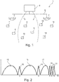
- an electronic price display system is shown as a system 1 according to the invention for communicating according to a time slot communication method, which is installed in the premises of a retail establishment is installed. For reasons of clarity, the figures do not show the premises and their furnishings.
- the system 1 has a server 2, a first and a second communication station 3 and 4 (referred to below as the station for short), and a number of eight radio tags 7-14 (referred to below as ESL for Electronic Shelf Label).
- the server is housed in offices and is connected to stations 3 and 4 via a wired communication line (LAN). Stations 3 and 4 are in contact with the ESL 7-14 via radio signals. Stations 3 and 4 are mounted in different positions on the ceiling in a sales room.
- the ESL 7 - 14 are attached to shelves corresponding to products for which the ESL 7 - 14 is used to display price and product information.
- the product information is transmitted from the server 2 to the stations 3, 4 and from there it is communicated individually to the individual ESLs 7-14.
- Each station 3, 4 covers a radio area, with a first radio area limit 5 of the station 3 and a second radio area limit 6 of the station 4 being indicated in some areas.
- the radio areas have an overlap area in which the ESL 9 - 11 are located.
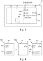
- Each station 3 or 4 knows the radio channels with the channel numbers 3, 5, 8, 9 and 10 preferred for the operation of the system 1. This is in the figure 2 shown, in which different frequency bands 15-22 are represented by channel numbers K wind. Frequency bands 15, 16 and 17 are available for operating a conventional WLAN. The frequency bands 18, 19, 20 - 22 preferred for the operation of system 1 correspond to channel numbers 3, 5, 8 - 10 and do not overlap with the WLAN frequency bands 15 - 17.
- Station 3 automatically selected the radio channel with channel number 3 , because this was the first to be checked to see whether it was already occupied by another station.
- Station 4 automatically selected the radio channel with channel number 5 because when it checked for free radio channels, it found that the radio channel with channel number 3 was already occupied and that the next free radio channel was channel number 5 has been identified. However, the assignment of the radio channels can also be fixed.
- the ESL 7 - 14 As soon as the ESL 7 - 14 are brought into the respective radio range of the station 3 or 4, they find that in one or more radio channels Radio signals of the applicable stations 3 and 4 exist.
- the ESL 7 and 8 establish a connection to the first station 3.
- the ESL 12 - 14 establish a connection to the second station 4.
- For the ESL 9 - 11 it is determined that both stations 3 and 4 are available for all of them.
- Each ESL 9 - 10 now checks the reception quality of the radio signals received from the respective station 3, 4 and decides on the station 3 or 4 for which the best reception quality was determined in order to establish a connection with it in the respective radio channel (channel number 3 or 5).
- this decision-making process can also be carried out by stations 3 and 4, with the stations checking the respective reception quality of a communication with the ESLs 9-11 and mutually agreeing on which of them will establish a connection with which of the ESLs 9-11 , because there are 9 - 11 more favorable communication conditions for the respective ESL.
- the decision-making regarding the association between the ESL 9 - 11 and the stations 3 , 4 can also be outsourced to the server 2 , since it is in contact with the stations 3 , 4 .
- radio channels are first selected (also referred to as "channel scan"), if necessary an evaluation of the reception quality on the respective radio channel is carried out and then unique hardware addresses of the ESL 7 -14 to the station 3, 4 selected for communication. Thus each station 3, 4 knows the ESL 7-14 assigned to it.
- each ESL 7 - 14 is assigned to exactly one product.
- the server gains knowledge of where in the salesroom, on which shelf and on which shelf position the respective ESL 7 - 14 is (or should be) because it also knows the corresponding position of the products, which is represented with the aid of a planogram.
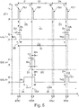
- the ESL 7 has a radio module 24, a processor 25 for processing data, for controlling operating states and for providing functions, a memory 26 for storing data and programs, and a display 27 realized in energy-saving electronic ink technology see full ad of the product information.
- the radio module 24 is used for radio-based communication with the stations 3 and 4, with reception data being generated from received radio signals and being transferred to the processor 25, or transmission data transferred from the processor 25 being converted into radio signals.
- the data stored in memory 26 may be associated with both processor 25 and display 27.
- the selected representation also does not distinguish what type of memory (ROM, EEPROM, RAM, etc.) is involved or how the memory 26 is logically or physically assigned to the processor 25 and/or the display 27. Connections such as signal and/or data lines between the function blocks 24 - 27 and the energy store (in the present case a battery) are also not shown in the selected representation.
- image data BD for generating an image using the display 27, the image data BD specifying a first image plane of the image with first-level data ED1 and a second image plane of the image with second-level data ED2, hardware Address data HAD for specifying the hardware address of the ESL and parameter data PD relating to the parameterization of the time slot communication method are stored. It should be mentioned at this point that other image planes can also be present.
- the hardware address data HAD comprises four bytes B3, B2, B1, B0, B0 being the least significant byte of the hardware address.
- Both the various plane data ED1 and ED2 are combined in the ESL 7 to form the overall image.
- Both the first and second level data ED1, ED2 represent image information about each pixel.
- specific image information is defined as "transparent", “background” or “background color” for both image planes.
- the individual image planes can therefore be superimposed pixel by pixel, i.e. the overall image can be built up by superimposing the image contents to identical coordinates of the pixels from different image planes.
- the images are in bitmap format, but they can also be in other formats such as JPG, etc.
- a first image level 28 represented by the first level data ED1 essentially contains static image information 29 on a product, with this static image information is only changed if the ESL 7 is assigned to another product.
- the static image information 29 relates to descriptive text about the product, for example. All other image areas are defined as "transparent”.
- a second image level 30, represented by the second level data ED2, essentially contains dynamic image information 31, which changes relatively often in comparison to the static image information, such as daily or several times a day or weekly.
- the dynamic image information 31 relates, for example, to the price of the product or also information on the validity of an offer, such as, for example, the start date and end date or times or other conditions that are linked to the offer.
- the entire image data BD can be received in compressed form at once, decompressed and stored in the memory 26. This can happen, for example, when the overall image is transmitted for the first time. However, the process is relatively lengthy and consequently causes a relatively high energy requirement. If the image once exists in the ESL 7, a partial update of the image is more efficient because this can be done in a more energy-efficient manner.
- the ESL 7 can receive the image plane to be updated (e.g. the second image plane 30) separately from the other image plane already stored in the memory 26 (e.g. the first image plane 28), decompress it and store it in the memory 26. Thereafter, the newly created second level data ED2 is accessed internally (switched from one memory page to another memory page) to rebuild the overall image 32 .
- the ESL 7 also has a timing stage 33 which can be implemented as an independent hardware component or at least partially with the aid of the processor 25 . It generates a time base typical of the ESL and uses this time base to control the timing (entering and leaving) of the states of the ESL 7. The timing is controlled, for example, with Using timing parameters inherently known to the timing circuit and/or provided by the processor.
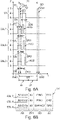
- the top sequence of states shows the states of stage 3 countersigned by ST. N time slots Z1 . . . ZN (eg 256) with an identical time slot duration DS (eg approx. 58 milliseconds) are available during a time slot cycle duration DC (eg 15 seconds).
- stage 3 changes between a transmission state T and an idle state R.
- the transmission state T is always assumed at the beginning of a time slot Z1 ... ZN and for a synchronization data signal duration DSD (or transmission duration DSD of the synchronization Data signal SD) maintained in order to send the respective applicable time slot symbol ZS1, ZS2, ... ZSN with the respective synchronization data signal SD.
- the consecutive number of the respective time slot Z1 ... ZN in the order in which the time slots Z1 ... ZN occur is used as the respective time slot cycle symbol ZS1 ... ZSN. Consequently, the first time slot Z1 in hexadecimal notation (identified by "Hex") with the time slot symbol Hex 00, the second time slot Z2 with the time slot symbol Hex 01 etc. and the last time slot ZN (in the present example the two hundred and fifty-sixth time slot Z256 with the time slot symbol Hex FF marked.
- the hardware addresses of the ESL 7 - 9 would be unchangeable in a real operation of the system 1.
- the ESLs of the system 1 will sometimes differ from figure to figure Hardware addresses assigned or even single or multiple ESL not included in the discussion.
- FIG 8 is the hardware address of the first ESL 7 hex B2:00:01:00, the second ESL 8 hex B2:00:01:01, the third ESL 9 hex B2:00:02:01 and the fourth ESL 10 hex B2 :00:03:01.
- the least significant byte B0 in the respective ESL 7-10 is used to identify a time slot that occurs as part of the time slot communication method and that is intended for the respective ESL 7-10.
- the remaining three bytes B1 - B3 of the hardware address are used to individually address an ESL 7 - 10 in the time slot Z1 ... ZN specified for the respective ESL.
- the first ESL 7 is in the more synchronous state. It wakes up from its sleep state S at a first wake-up time TA1 and changes to its ready-to-receive active state E with a relatively short lead time DV before an expected occurrence of a synchronization data signal SD, receives the synchronization data signal SD during a reception period DE with the first timeslot symbol ZS1 (Hex 00), determines by comparing the least significant byte B0 of its hardware address (Hex 00) with the received timeslot symbol ZS1 that the first timeslot Z1 intended for the first ESL 7 is indicated (correspondence of the bytes to be compared: B0 of the hardware address and first time slot symbol ZS1), retains the parameters of the time control stage 33 used to control the wake-up for waking up in the subsequent time slot cycle for the purpose of defining the new wake-up time and switches back to the sleep state S with a relatively short follow-up time DN, order after the expiry of the provided Sleep state dwell time DR
- the third ESL 9 is in the asynchronous state before a synchronization point in time TSY, which is indicated by the broken line of the arrow 34 running parallel to the time axis. It wakes up at a randomly selected first wake-up time TA1 and changes from its sleep state S to the active state E ready to receive and waits in this state until the next occurrence of the synchronization data signal SD is received, with the second time slot symbol ZS2 ( Hex 01) is received.
- the third ESL 9 recognizes from the least significant byte B0 (Hex 00) of its hardware address that the specific time slot in the present time slot cycle already belongs to the past and consequently the next time slot with the time slot symbol Hex 00 is only to be expected in the next time slot cycle , and calculates that the currently recognized time slot Z2 is one time slot next to its original time slot Z1, which is referred to below as the time slot difference.
- the time control stage 33 is now programmed so that the new wake-up time TA2 lies before the occurrence of the first time slot Z1 of the subsequent time slot cycle, as in the case of an ESL in the synchronous state with said lead time DV.
- the waiting time DSA in the sleep state S is calculated as follows: sleep state dwell time DR (in the synchronous state) minus the time slot duration DS multiplied by the time slot difference (value 1 in the present case).
- the third ESL 9 is thus again in the synchronous state, which is indicated by the arrow 35 with a solid line, and changes from the active state E to the sleep state S, after the dwell time DAS has elapsed at the new wake-up time TA2 Active state E to switch.
- a “PING” command is transmitted to the first ESL 7, a “PING” command is likewise transmitted to the second ESL 8, and a “SWPAG2” command is transmitted to the third ESL 9.
- These commands are single time slot commands which are processed immediately after their decoding in the relevant ESL 7 - 9 with a negligible expenditure of time.
- the two "PING" commands are used to test whether the addressed ESL 7, 8 reports back with confirmation data ACD, ie whether it exists or whether it reacts at all and is synchronized.
- the "SWAPG2" command causes the third ESL 9 to switch from a (first) current memory page (or memory page) to a second memory page (or memory page) in order, for example, to change the image to be displayed using the display 27, just like this in connection with the figure 4 was discussed.
- the synchronization data signal SD is used to transmit a confirmation time for the first ESL 7 by specifying a first idle period DR1, for the second ESL 8 by specifying a second idle period DR2 and for the third ESL 9 by specifying a third idle period DR3.
- the reference point for the three idle periods DR1 - DR3 is always the end of the reception period DE.
- the data structure transmitted using the synchronization data signal SD at the beginning of the first time slot Z1 is in FIG Figure 6B visualized.
- maximum time periods for responses can also be specified, which result from the sum of the respective idle time periods DR1-DR3 and the time period for delivering the confirmation data ACD.
- FIG. 7A shows the processing of a multiple time slot command, in which the first ESL 7 splits overall data (e.g. relating to an entire image to be displayed or just one image plane of the image) over three adjacent time slots Z1 - Z3 into three data packets DAT1 - DAT3 from station 3 receives.
- overall data e.g. relating to an entire image to be displayed or just one image plane of the image
- the first ESL 7 recognizes its synchronous state and that it is individually addressed (addressees Hex B2:00:01), receives and decodes a "DATA_INIT" command with which it receives the three data packets DAT1 - DAT3 is commanded in said time slots Z1 - Z3, and at the end of the receiving period DE goes into the sleep state S for a first waiting period DW1, the first waiting period DW1 ending at the end of the first half of the time slot period DS.
- the station 3 At the beginning of the second part 37 of the first time slot Z1, the station 3 goes into its transmit state T and the first ESL 7 into its ready-to-receive active state E, so that it receives the first data packet DAT1 during a data transmission period DT. It then confirms successful reception with the aid of partial confirmation data ACD1 during a confirmation period DA, during which station 3 is also in reception state E.
- the confirmation period DA ends before the end of the first time slot Z1.
- the first ESL 7 After the confirmation period DA has elapsed, the first ESL 7 remains in the sleep state S for a second waiting period DW2, which lasts until the end of the first part 36 of the second (subsequent) time slot Z2.
- the first ESL 7 recognizes its synchronous status (least significant byte B0 of the hardware address is hex 00) and that it is individually addressed (address data hex B2:00:01), receives and decodes a "DATA_INIT "Command with which it is ordered to receive three data packets DAT1 - DAT3 in the time slots Z1 - Z3.
- the data structure transmitted using the synchronization data signal SD at the beginning of the first time slot Z1 is in FIG Figure 8B visualized.
- the data transfer from station 3 to the first ESL 7 is analogous to the discussion in FIG Figure 7A .
- the three remaining ESLs 8 - 10 recognize that they are synchronous because the second time slot symbol Z2 indicates the time slot intended for them (least significant byte B0 of the hardware address is hex 01 for all three ESLs 8 - 10).
- Checking the address data AD shows that each ESL 8 - 10 is addressed individually (existence of the remaining three bytes B1 - B3 of the respective hardware address in the address data AD), the commands intended for the respective ESL 8 - 10 are decoded (In this case, three "PING" commands) and executed immediately, and the individual confirmation data ACD after an elapse of the individual idle time periods DR1 - DR3 to the station 3, as is the case for the Figure 6A was discussed.
- the data structure transmitted using the synchronization data signal SD at the start of the second time slot Z2 is in FIG Figure 8C visualized.
- the three single-timeslot commands and the multiple-timeslot command in the second timeslot T2 are treated more or less simultaneously in relation to the "timeslot" time unit, since the first part 36 for the single-timeslot commands and the second part for the multiple-timeslot command 37 of the second time slot Z2 is reserved for the data communication required in each case.
- the assignment of the respective command type to the parts of the time slot 36, 37 can also be reversed.
Landscapes
- Engineering & Computer Science (AREA)
- Physics & Mathematics (AREA)
- Health & Medical Sciences (AREA)
- Toxicology (AREA)
- Business, Economics & Management (AREA)
- General Physics & Mathematics (AREA)
- Theoretical Computer Science (AREA)
- Strategic Management (AREA)
- Finance (AREA)
- Accounting & Taxation (AREA)
- Development Economics (AREA)
- Computer Networks & Wireless Communication (AREA)
- Computer Vision & Pattern Recognition (AREA)
- General Health & Medical Sciences (AREA)
- Electromagnetism (AREA)
- Artificial Intelligence (AREA)
- Marketing (AREA)
- Game Theory and Decision Science (AREA)
- Entrepreneurship & Innovation (AREA)
- Economics (AREA)
- General Business, Economics & Management (AREA)
- Signal Processing (AREA)
- Mobile Radio Communication Systems (AREA)
- Near-Field Transmission Systems (AREA)
- Time-Division Multiplex Systems (AREA)
Priority Applications (1)
| Application Number | Priority Date | Filing Date | Title |
|---|---|---|---|
| EP18193360.7A EP3444769B1 (de) | 2014-02-20 | 2014-02-20 | System für zeitschlitzkommunikation |
Applications Claiming Priority (3)
| Application Number | Priority Date | Filing Date | Title |
|---|---|---|---|
| EP14707354.8A EP3108429B1 (de) | 2014-02-20 | 2014-02-20 | System für zeitschlitzkommunikation |
| PCT/EP2014/053376 WO2015124197A1 (de) | 2014-02-20 | 2014-02-20 | System für zeitschlitzkommunikation |
| EP18193360.7A EP3444769B1 (de) | 2014-02-20 | 2014-02-20 | System für zeitschlitzkommunikation |
Related Parent Applications (2)
| Application Number | Title | Priority Date | Filing Date |
|---|---|---|---|
| EP14707354.8A Division EP3108429B1 (de) | 2014-02-20 | 2014-02-20 | System für zeitschlitzkommunikation |
| EP14707354.8A Division-Into EP3108429B1 (de) | 2014-02-20 | 2014-02-20 | System für zeitschlitzkommunikation |
Publications (2)
| Publication Number | Publication Date |
|---|---|
| EP3444769A1 EP3444769A1 (de) | 2019-02-20 |
| EP3444769B1 true EP3444769B1 (de) | 2022-06-15 |
Family
ID=50190417
Family Applications (6)
| Application Number | Title | Priority Date | Filing Date |
|---|---|---|---|
| EP18193360.7A Active EP3444769B1 (de) | 2014-02-20 | 2014-02-20 | System für zeitschlitzkommunikation |
| EP14707354.8A Active EP3108429B1 (de) | 2014-02-20 | 2014-02-20 | System für zeitschlitzkommunikation |
| EP18193356.5A Active EP3444768B1 (de) | 2014-02-20 | 2014-02-20 | System für zeitschlitzkommunikation |
| EP19216347.5A Active EP3657424B1 (de) | 2014-02-20 | 2014-02-20 | System für zeitschlitzkommunikation |
| EP18193354.0A Active EP3444767B1 (de) | 2014-02-20 | 2014-02-20 | System für zeitschlitzkommunikation |
| EP18201448.0A Active EP3467756B1 (de) | 2014-02-20 | 2014-02-20 | Funk-tag für zeitschlitzkommunikation |
Family Applications After (5)
| Application Number | Title | Priority Date | Filing Date |
|---|---|---|---|
| EP14707354.8A Active EP3108429B1 (de) | 2014-02-20 | 2014-02-20 | System für zeitschlitzkommunikation |
| EP18193356.5A Active EP3444768B1 (de) | 2014-02-20 | 2014-02-20 | System für zeitschlitzkommunikation |
| EP19216347.5A Active EP3657424B1 (de) | 2014-02-20 | 2014-02-20 | System für zeitschlitzkommunikation |
| EP18193354.0A Active EP3444767B1 (de) | 2014-02-20 | 2014-02-20 | System für zeitschlitzkommunikation |
| EP18201448.0A Active EP3467756B1 (de) | 2014-02-20 | 2014-02-20 | Funk-tag für zeitschlitzkommunikation |
Country Status (15)
| Country | Link |
|---|---|
| US (1) | US9792468B2 (enExample) |
| EP (6) | EP3444769B1 (enExample) |
| JP (1) | JP6228687B2 (enExample) |
| AU (1) | AU2014383584B2 (enExample) |
| BR (1) | BR112016018902B1 (enExample) |
| CA (1) | CA2939471C (enExample) |
| DK (1) | DK3108429T3 (enExample) |
| ES (1) | ES2705874T3 (enExample) |
| MX (1) | MX358729B (enExample) |
| RU (1) | RU2698915C2 (enExample) |
| SG (1) | SG11201606588UA (enExample) |
| SI (1) | SI3108429T1 (enExample) |
| SM (1) | SMT201900028T1 (enExample) |
| WO (1) | WO2015124197A1 (enExample) |
| ZA (1) | ZA201605314B (enExample) |
Families Citing this family (32)
| Publication number | Priority date | Publication date | Assignee | Title |
|---|---|---|---|---|
| EP3444769B1 (de) * | 2014-02-20 | 2022-06-15 | SES-imagotag GmbH | System für zeitschlitzkommunikation |
| EP3387584B1 (de) * | 2015-12-10 | 2020-10-07 | SES-imagotag GmbH | Anzeigevorrichtung zum anzeigen einer preis- und/oder produktinformation |
| US10068113B2 (en) * | 2016-08-16 | 2018-09-04 | Ses-Imagotag Gmbh | Time slot communication system |
| US10045296B2 (en) * | 2016-12-20 | 2018-08-07 | Intel IP Corporation | Method and apparatus to controlling sleep time for Bluetooth device and Bluetooth enabled device |
| US10510042B2 (en) * | 2017-09-29 | 2019-12-17 | Sensormatic Electronics, LLC | Systems and methods for determining inventory using time-slotted tag communications |
| JP7254889B2 (ja) * | 2018-08-07 | 2023-04-10 | 株式会社東芝 | 無線送電装置及び無線送電方法 |
| JP2020025400A (ja) * | 2018-08-07 | 2020-02-13 | 株式会社東芝 | 無線送電装置及び無線送電方法 |
| JP6682666B2 (ja) * | 2019-01-08 | 2020-04-15 | エスエーエス−イマーゴタグ・ゲゼルシャフト・ミト・ベシュレンクテル・ハフツング | タイムスロット通信システム |
| CN109587778B (zh) * | 2019-01-18 | 2022-02-08 | 重庆物奇科技有限公司 | 用于电子价签的通信方法 |
| WO2020249231A1 (de) | 2019-06-14 | 2020-12-17 | Ses-Imagotag Gmbh | Elektronisches regaletiketten-system mit energieversorgung |
| WO2020249251A1 (de) | 2019-06-14 | 2020-12-17 | Ses-Imagotag Gmbh | Elektronisches regaletiketten-system mit regalschienen-subsystem |
| US11995500B2 (en) | 2019-06-14 | 2024-05-28 | Vusiongroup Gmbh | Method for locating an electronic shelf label |
| CN114222994B (zh) | 2019-08-19 | 2025-02-28 | 福森集团有限责任公司 | 带有非接触式的货架标签能量供应和/或数据供应的电子货架标签系统 |
| CN119992957A (zh) | 2019-11-22 | 2025-05-13 | 福森集团有限责任公司 | 用电池组供电的电子标签 |
| EP4081894B1 (de) | 2019-12-23 | 2025-06-11 | VusionGroup GmbH | Elektronisches regaletikett mit aktionsauslösung |
| WO2021129933A1 (de) | 2019-12-23 | 2021-07-01 | Ses-Imagotag Gmbh | Elektronisches regaletiketten-system mit regalschienen-sub-system |
| EP4245054B1 (de) * | 2020-11-12 | 2025-11-12 | VusionGroup GmbH | Verfahren zur funk-kanalzuweisung in einem elektronischen anzeige-system |
| WO2022135716A1 (de) | 2020-12-23 | 2022-06-30 | Ses-Imagotag Gmbh | Befestigungselement zum befestigen bzw. fixieren einer anzeigeeinheit an einer tragevorrichtung |
| AU2021432821B2 (en) | 2021-03-09 | 2025-01-30 | Vusiongroup Gmbh | Bus system and support device comprising such a bus system |
| EP4323985A1 (de) | 2021-04-13 | 2024-02-21 | SES-Imagotag GmbH | Tragevorrichtung zum tragen eines elektronischen gerätes innerhalb eines aufnahmeraums der tragevorrichtung. |
| EP4364065A1 (en) | 2021-07-02 | 2024-05-08 | VusionGroup GmbH | Method of guiding a person to products |
| DE202021004412U1 (de) | 2021-10-14 | 2024-04-24 | Vusiongroup Sa | System zum logischen Verknüpfen einer elektronischen Anzeigeeinheit mit einem Produkt |
| EP4416661A1 (de) | 2021-10-14 | 2024-08-21 | Vusiongroup Sa | Verfahren zum logischen verknüpfen einer elektronischen anzeigeeinheit mit einem produkt |
| KR20240118117A (ko) | 2021-12-18 | 2024-08-02 | 부전그룹 게엠베하 | 쇼핑시 시각 장애인 또는 맹인을 도와주는 장치 |
| DE202021004436U1 (de) | 2021-12-18 | 2024-07-11 | Vusiongroup Gmbh | Vorrichtung zur Unterstützung von sehbehinderten oder blinden Personen beim Einkaufen |
| AU2021479950A1 (en) | 2021-12-23 | 2024-05-30 | Pdi Digital Gmbh | Electronic display device with an acceleration sensor |
| JP2025535648A (ja) | 2022-10-07 | 2025-10-28 | ヴジョングループ・ソシエテ・アノニム | 機能を起動するコンピュータ実装方法 |
| WO2024098364A1 (en) * | 2022-11-11 | 2024-05-16 | Qualcomm Incorporated | Managing timing of electronic shelf label connections |
| AU2024215904A1 (en) | 2023-01-31 | 2025-08-14 | Pdi Digital Gmbh | Battery-operated devices, initiator device and communication system formed therewith |
| WO2024245553A1 (de) | 2023-05-31 | 2024-12-05 | Pdi Digital Gmbh | Elektronische anzeigevorrichtung mit einem bewegungssensor |
| WO2024245554A1 (de) | 2023-05-31 | 2024-12-05 | Vusiongroup Gmbh | Verfahren zum erfassen von einem, insbesondere ortsvariablen, funk-etikett |
| DE202024102824U1 (de) | 2023-05-31 | 2024-07-03 | Pdi Digital Gmbh | Elektronische Anzeigevorrichtung mit einem Bewegungssensor |
Family Cites Families (13)
| Publication number | Priority date | Publication date | Assignee | Title |
|---|---|---|---|---|
| DE4439074C2 (de) | 1994-11-02 | 1998-09-17 | Pricer Ab | Anlage zur elektronischen Preisanzeige |
| US6044359A (en) * | 1997-11-13 | 2000-03-28 | Ncr Corporation | Method of minimizing power consumption within an electronic price label |
| JP3300280B2 (ja) * | 1998-04-23 | 2002-07-08 | インターナショナル・ビジネス・マシーンズ・コーポレーション | 画像合成処理装置およびその方法 |
| CA2477696A1 (en) * | 2002-02-28 | 2003-09-04 | Pricer Ab | System and method for updating electronic label displays |
| KR100771466B1 (ko) * | 2006-04-27 | 2007-10-30 | 김정선 | 재난 구조용 GPS주파수가 130 dBm 펄스 폭에 형성된5 ㎓ 밀리미터파 주파수대역을 이용한 초 광대역주파수확장변조 복합무선통신시스템 |
| JP2008168057A (ja) * | 2007-01-15 | 2008-07-24 | Ishida Co Ltd | 電子棚札及び電子棚札システム |
| GB0812770D0 (en) | 2008-07-11 | 2008-08-20 | Zbd Displays Ltd | A display system |
| JP5125972B2 (ja) * | 2008-10-09 | 2013-01-23 | カシオ計算機株式会社 | 無線端末装置、無線中継装置及びプログラム |
| US8525642B2 (en) * | 2009-05-08 | 2013-09-03 | Icontrol, Inc. | Methods and systems for communication protocol for distributed asset management |
| JP2011171993A (ja) * | 2010-02-18 | 2011-09-01 | Seiko Instruments Inc | 情報処理装置、及び無線端末 |
| WO2011163385A1 (en) * | 2010-06-23 | 2011-12-29 | Savi Technology, Inc. | Apparatus and method for management of power constrained wireless devices |
| TWM418349U (en) * | 2011-06-24 | 2011-12-11 | Ceramicro Technology Corp | Electronic label time-division control system |
| EP3444769B1 (de) | 2014-02-20 | 2022-06-15 | SES-imagotag GmbH | System für zeitschlitzkommunikation |
-
2014
- 2014-02-20 EP EP18193360.7A patent/EP3444769B1/de active Active
- 2014-02-20 AU AU2014383584A patent/AU2014383584B2/en active Active
- 2014-02-20 EP EP14707354.8A patent/EP3108429B1/de active Active
- 2014-02-20 CA CA2939471A patent/CA2939471C/en active Active
- 2014-02-20 SM SM20190028T patent/SMT201900028T1/it unknown
- 2014-02-20 EP EP18193356.5A patent/EP3444768B1/de active Active
- 2014-02-20 DK DK14707354.8T patent/DK3108429T3/en active
- 2014-02-20 SG SG11201606588UA patent/SG11201606588UA/en unknown
- 2014-02-20 US US15/119,259 patent/US9792468B2/en active Active
- 2014-02-20 WO PCT/EP2014/053376 patent/WO2015124197A1/de not_active Ceased
- 2014-02-20 EP EP19216347.5A patent/EP3657424B1/de active Active
- 2014-02-20 RU RU2016133391A patent/RU2698915C2/ru active
- 2014-02-20 EP EP18193354.0A patent/EP3444767B1/de active Active
- 2014-02-20 ES ES14707354T patent/ES2705874T3/es active Active
- 2014-02-20 MX MX2016010597A patent/MX358729B/es active IP Right Grant
- 2014-02-20 JP JP2016551783A patent/JP6228687B2/ja active Active
- 2014-02-20 BR BR112016018902-7A patent/BR112016018902B1/pt active IP Right Grant
- 2014-02-20 EP EP18201448.0A patent/EP3467756B1/de active Active
- 2014-02-20 SI SI201431040T patent/SI3108429T1/sl unknown
-
2016
- 2016-08-01 ZA ZA2016/05314A patent/ZA201605314B/en unknown
Also Published As
| Publication number | Publication date |
|---|---|
| EP3444768A1 (de) | 2019-02-20 |
| BR112016018902B1 (pt) | 2021-01-26 |
| SG11201606588UA (en) | 2016-09-29 |
| EP3444767A1 (de) | 2019-02-20 |
| ZA201605314B (en) | 2022-02-23 |
| AU2014383584B2 (en) | 2018-05-10 |
| EP3467756B1 (de) | 2019-12-11 |
| US9792468B2 (en) | 2017-10-17 |
| MX2016010597A (es) | 2017-05-04 |
| RU2698915C2 (ru) | 2019-09-02 |
| EP3444767B1 (de) | 2021-05-12 |
| WO2015124197A1 (de) | 2015-08-27 |
| EP3467756A1 (de) | 2019-04-10 |
| EP3657424B1 (de) | 2024-12-04 |
| JP6228687B2 (ja) | 2017-11-08 |
| SMT201900028T1 (it) | 2019-02-28 |
| EP3108429B1 (de) | 2018-10-31 |
| MX358729B (es) | 2018-09-03 |
| CA2939471C (en) | 2018-10-09 |
| ES2705874T3 (es) | 2019-03-26 |
| EP3444768B1 (de) | 2021-05-12 |
| JP2017507598A (ja) | 2017-03-16 |
| DK3108429T3 (en) | 2019-02-18 |
| US20170011238A1 (en) | 2017-01-12 |
| EP3657424A1 (de) | 2020-05-27 |
| AU2014383584A1 (en) | 2016-09-29 |
| EP3657424C0 (de) | 2024-12-04 |
| CA2939471A1 (en) | 2015-08-27 |
| EP3444769A1 (de) | 2019-02-20 |
| RU2016133391A (ru) | 2018-02-20 |
| EP3108429A1 (de) | 2016-12-28 |
| SI3108429T1 (sl) | 2019-03-29 |
Similar Documents
| Publication | Publication Date | Title |
|---|---|---|
| EP3444769B1 (de) | System für zeitschlitzkommunikation | |
| EP3387585B1 (de) | Anzeigevorrichtung mit steuerbarer verarbeitungsstufe | |
| EP2202599B1 (de) | Vernetzte Industriesteuerung und Verfahren zum Wechsel des Betriebsmodus einer solchen Industriesteuerung | |
| EP3143422B1 (de) | Verfahren zum orten eines funk-tags | |
| EP3198967B1 (de) | Funk-basisstation und system mit besagter funk-basisstation | |
| EP1815650A1 (de) | Verfahren zur synchronisation und datenuebertragung | |
| DE102004055666A1 (de) | Klimatisierungssystem zum Integrieren mehrerer Bereiche | |
| EP3984259B1 (de) | Elektronisches regaletiketten-system mit regalschienen-subsystem | |
| WO2006029426A1 (de) | Verfahren zum erstellen von kommunikationsplänen für ein verteiltes echtzeit-computersystem | |
| DE102010028665A1 (de) | Verfahren zum Wechseln eines Betriebszustands mindestens einer Vorrichtung | |
| EP3871338A1 (de) | Funk-basisstation zur kombinierten funk-kommunikation | |
| DE69319305T2 (de) | Aufrufdatenübertragungsnetz | |
| DE112016006338B4 (de) | Kommunikationsvorrichtung, Kommunikationssystem und Kommunikationsverfahren | |
| EP4245054B1 (de) | Verfahren zur funk-kanalzuweisung in einem elektronischen anzeige-system | |
| AT408819B (de) | Regel- und/oder steuervorrichtung für die objektleittechnik | |
| DE102012210959A1 (de) | Steuerungssystem für verteilt angeordnete Verbraucher und Verfahren zur Inbetriebnahme des Systems | |
| EP3183845A1 (de) | Switch-einheit, ethernet-netzwerk und verfahren zur aktivierung von komponenten in einem ethernet-netzwerk | |
| WO2016079091A1 (de) | Verfahren zum betreiben eines ersten und zumindest eines zweiten feldgerätes | |
| DE102012106449A1 (de) | Speicherung einer Soll-Adresse in einem Gerät einer Steuerungsanlage | |
| EP2156621A1 (de) | Verfahren zum betreiben eines kommunikationssystems, koordinationsknoten eines kommunikationssystems sowie kommunikationssystem | |
| DE102022210455A1 (de) | System zur beleuchtungssteuerung | |
| DE102004007151A1 (de) | Verfahren und Vorrichtung zur Überwachung und Beeinflussung von Versorgungsmodulen für Verbraucher | |
| EP1536571A1 (de) | Bussystem zum Steuern elektrischer Verbraucher über das elektrische Netz |
Legal Events
| Date | Code | Title | Description |
|---|---|---|---|
| PUAI | Public reference made under article 153(3) epc to a published international application that has entered the european phase |
Free format text: ORIGINAL CODE: 0009012 |
|
| STAA | Information on the status of an ep patent application or granted ep patent |
Free format text: STATUS: THE APPLICATION HAS BEEN PUBLISHED |
|
| AC | Divisional application: reference to earlier application |
Ref document number: 3108429 Country of ref document: EP Kind code of ref document: P |
|
| AK | Designated contracting states |
Kind code of ref document: A1 Designated state(s): AL AT BE BG CH CY CZ DE DK EE ES FI FR GB GR HR HU IE IS IT LI LT LU LV MC MK MT NL NO PL PT RO RS SE SI SK SM TR |
|
| STAA | Information on the status of an ep patent application or granted ep patent |
Free format text: STATUS: REQUEST FOR EXAMINATION WAS MADE |
|
| 17P | Request for examination filed |
Effective date: 20190802 |
|
| RAP1 | Party data changed (applicant data changed or rights of an application transferred) |
Owner name: SES-IMAGOTAG GMBH |
|
| RBV | Designated contracting states (corrected) |
Designated state(s): AL AT BE BG CH CY CZ DE DK EE ES FI FR GB GR HR HU IE IS IT LI LT LU LV MC MK MT NL NO PL PT RO RS SE SI SK SM TR |
|
| STAA | Information on the status of an ep patent application or granted ep patent |
Free format text: STATUS: EXAMINATION IS IN PROGRESS |
|
| 17Q | First examination report despatched |
Effective date: 20201217 |
|
| REG | Reference to a national code |
Ref country code: DE Ref legal event code: R079 Ref document number: 502014016291 Country of ref document: DE Free format text: PREVIOUS MAIN CLASS: G06Q0030020000 Ipc: G06K0007100000 |
|
| RIC1 | Information provided on ipc code assigned before grant |
Ipc: G06Q 30/02 20120101ALI20211122BHEP Ipc: G06K 7/10 20060101AFI20211122BHEP |
|
| GRAP | Despatch of communication of intention to grant a patent |
Free format text: ORIGINAL CODE: EPIDOSNIGR1 |
|
| STAA | Information on the status of an ep patent application or granted ep patent |
Free format text: STATUS: GRANT OF PATENT IS INTENDED |
|
| INTG | Intention to grant announced |
Effective date: 20220119 |
|
| RIN1 | Information on inventor provided before grant (corrected) |
Inventor name: FRIESSNEGG, CHRISTIAN Inventor name: HECHENBLAICKNER, ANDREAS Inventor name: ROESSL, ANDREAS |
|
| GRAS | Grant fee paid |
Free format text: ORIGINAL CODE: EPIDOSNIGR3 |
|
| GRAA | (expected) grant |
Free format text: ORIGINAL CODE: 0009210 |
|
| STAA | Information on the status of an ep patent application or granted ep patent |
Free format text: STATUS: THE PATENT HAS BEEN GRANTED |
|
| AC | Divisional application: reference to earlier application |
Ref document number: 3108429 Country of ref document: EP Kind code of ref document: P |
|
| AK | Designated contracting states |
Kind code of ref document: B1 Designated state(s): AL AT BE BG CH CY CZ DE DK EE ES FI FR GB GR HR HU IE IS IT LI LT LU LV MC MK MT NL NO PL PT RO RS SE SI SK SM TR |
|
| REG | Reference to a national code |
Ref country code: CH Ref legal event code: EP Ref country code: GB Ref legal event code: FG4D Free format text: NOT ENGLISH |
|
| REG | Reference to a national code |
Ref country code: IE Ref legal event code: FG4D Free format text: LANGUAGE OF EP DOCUMENT: GERMAN |
|
| REG | Reference to a national code |
Ref country code: DE Ref legal event code: R096 Ref document number: 502014016291 Country of ref document: DE |
|
| REG | Reference to a national code |
Ref country code: AT Ref legal event code: REF Ref document number: 1498821 Country of ref document: AT Kind code of ref document: T Effective date: 20220715 |
|
| REG | Reference to a national code |
Ref country code: SE Ref legal event code: TRGR |
|
| REG | Reference to a national code |
Ref country code: LT Ref legal event code: MG9D |
|
| REG | Reference to a national code |
Ref country code: NL Ref legal event code: MP Effective date: 20220615 |
|
| PG25 | Lapsed in a contracting state [announced via postgrant information from national office to epo] |
Ref country code: NO Free format text: LAPSE BECAUSE OF FAILURE TO SUBMIT A TRANSLATION OF THE DESCRIPTION OR TO PAY THE FEE WITHIN THE PRESCRIBED TIME-LIMIT Effective date: 20220915 Ref country code: LT Free format text: LAPSE BECAUSE OF FAILURE TO SUBMIT A TRANSLATION OF THE DESCRIPTION OR TO PAY THE FEE WITHIN THE PRESCRIBED TIME-LIMIT Effective date: 20220615 Ref country code: HR Free format text: LAPSE BECAUSE OF FAILURE TO SUBMIT A TRANSLATION OF THE DESCRIPTION OR TO PAY THE FEE WITHIN THE PRESCRIBED TIME-LIMIT Effective date: 20220615 Ref country code: GR Free format text: LAPSE BECAUSE OF FAILURE TO SUBMIT A TRANSLATION OF THE DESCRIPTION OR TO PAY THE FEE WITHIN THE PRESCRIBED TIME-LIMIT Effective date: 20220916 Ref country code: FI Free format text: LAPSE BECAUSE OF FAILURE TO SUBMIT A TRANSLATION OF THE DESCRIPTION OR TO PAY THE FEE WITHIN THE PRESCRIBED TIME-LIMIT Effective date: 20220615 Ref country code: BG Free format text: LAPSE BECAUSE OF FAILURE TO SUBMIT A TRANSLATION OF THE DESCRIPTION OR TO PAY THE FEE WITHIN THE PRESCRIBED TIME-LIMIT Effective date: 20220915 |
|
| PG25 | Lapsed in a contracting state [announced via postgrant information from national office to epo] |
Ref country code: RS Free format text: LAPSE BECAUSE OF FAILURE TO SUBMIT A TRANSLATION OF THE DESCRIPTION OR TO PAY THE FEE WITHIN THE PRESCRIBED TIME-LIMIT Effective date: 20220615 Ref country code: LV Free format text: LAPSE BECAUSE OF FAILURE TO SUBMIT A TRANSLATION OF THE DESCRIPTION OR TO PAY THE FEE WITHIN THE PRESCRIBED TIME-LIMIT Effective date: 20220615 |
|
| PG25 | Lapsed in a contracting state [announced via postgrant information from national office to epo] |
Ref country code: NL Free format text: LAPSE BECAUSE OF FAILURE TO SUBMIT A TRANSLATION OF THE DESCRIPTION OR TO PAY THE FEE WITHIN THE PRESCRIBED TIME-LIMIT Effective date: 20220615 |
|
| PG25 | Lapsed in a contracting state [announced via postgrant information from national office to epo] |
Ref country code: SM Free format text: LAPSE BECAUSE OF FAILURE TO SUBMIT A TRANSLATION OF THE DESCRIPTION OR TO PAY THE FEE WITHIN THE PRESCRIBED TIME-LIMIT Effective date: 20220615 Ref country code: SK Free format text: LAPSE BECAUSE OF FAILURE TO SUBMIT A TRANSLATION OF THE DESCRIPTION OR TO PAY THE FEE WITHIN THE PRESCRIBED TIME-LIMIT Effective date: 20220615 Ref country code: RO Free format text: LAPSE BECAUSE OF FAILURE TO SUBMIT A TRANSLATION OF THE DESCRIPTION OR TO PAY THE FEE WITHIN THE PRESCRIBED TIME-LIMIT Effective date: 20220615 Ref country code: PT Free format text: LAPSE BECAUSE OF FAILURE TO SUBMIT A TRANSLATION OF THE DESCRIPTION OR TO PAY THE FEE WITHIN THE PRESCRIBED TIME-LIMIT Effective date: 20221017 Ref country code: ES Free format text: LAPSE BECAUSE OF FAILURE TO SUBMIT A TRANSLATION OF THE DESCRIPTION OR TO PAY THE FEE WITHIN THE PRESCRIBED TIME-LIMIT Effective date: 20220615 Ref country code: EE Free format text: LAPSE BECAUSE OF FAILURE TO SUBMIT A TRANSLATION OF THE DESCRIPTION OR TO PAY THE FEE WITHIN THE PRESCRIBED TIME-LIMIT Effective date: 20220615 Ref country code: CZ Free format text: LAPSE BECAUSE OF FAILURE TO SUBMIT A TRANSLATION OF THE DESCRIPTION OR TO PAY THE FEE WITHIN THE PRESCRIBED TIME-LIMIT Effective date: 20220615 |
|
| PG25 | Lapsed in a contracting state [announced via postgrant information from national office to epo] |
Ref country code: PL Free format text: LAPSE BECAUSE OF FAILURE TO SUBMIT A TRANSLATION OF THE DESCRIPTION OR TO PAY THE FEE WITHIN THE PRESCRIBED TIME-LIMIT Effective date: 20220615 Ref country code: IS Free format text: LAPSE BECAUSE OF FAILURE TO SUBMIT A TRANSLATION OF THE DESCRIPTION OR TO PAY THE FEE WITHIN THE PRESCRIBED TIME-LIMIT Effective date: 20221015 |
|
| REG | Reference to a national code |
Ref country code: DE Ref legal event code: R097 Ref document number: 502014016291 Country of ref document: DE |
|
| PG25 | Lapsed in a contracting state [announced via postgrant information from national office to epo] |
Ref country code: AL Free format text: LAPSE BECAUSE OF FAILURE TO SUBMIT A TRANSLATION OF THE DESCRIPTION OR TO PAY THE FEE WITHIN THE PRESCRIBED TIME-LIMIT Effective date: 20220615 |
|
| PLBE | No opposition filed within time limit |
Free format text: ORIGINAL CODE: 0009261 |
|
| STAA | Information on the status of an ep patent application or granted ep patent |
Free format text: STATUS: NO OPPOSITION FILED WITHIN TIME LIMIT |
|
| PG25 | Lapsed in a contracting state [announced via postgrant information from national office to epo] |
Ref country code: DK Free format text: LAPSE BECAUSE OF FAILURE TO SUBMIT A TRANSLATION OF THE DESCRIPTION OR TO PAY THE FEE WITHIN THE PRESCRIBED TIME-LIMIT Effective date: 20220615 |
|
| 26N | No opposition filed |
Effective date: 20230316 |
|
| PG25 | Lapsed in a contracting state [announced via postgrant information from national office to epo] |
Ref country code: SI Free format text: LAPSE BECAUSE OF FAILURE TO SUBMIT A TRANSLATION OF THE DESCRIPTION OR TO PAY THE FEE WITHIN THE PRESCRIBED TIME-LIMIT Effective date: 20220615 |
|
| P01 | Opt-out of the competence of the unified patent court (upc) registered |
Effective date: 20230428 |
|
| PG25 | Lapsed in a contracting state [announced via postgrant information from national office to epo] |
Ref country code: MC Free format text: LAPSE BECAUSE OF FAILURE TO SUBMIT A TRANSLATION OF THE DESCRIPTION OR TO PAY THE FEE WITHIN THE PRESCRIBED TIME-LIMIT Effective date: 20220615 |
|
| REG | Reference to a national code |
Ref country code: CH Ref legal event code: PL |
|
| REG | Reference to a national code |
Ref country code: BE Ref legal event code: MM Effective date: 20230228 |
|
| PG25 | Lapsed in a contracting state [announced via postgrant information from national office to epo] |
Ref country code: LU Free format text: LAPSE BECAUSE OF NON-PAYMENT OF DUE FEES Effective date: 20230220 Ref country code: LI Free format text: LAPSE BECAUSE OF NON-PAYMENT OF DUE FEES Effective date: 20230228 Ref country code: CH Free format text: LAPSE BECAUSE OF NON-PAYMENT OF DUE FEES Effective date: 20230228 |
|
| REG | Reference to a national code |
Ref country code: IE Ref legal event code: MM4A |
|
| PG25 | Lapsed in a contracting state [announced via postgrant information from national office to epo] |
Ref country code: IT Free format text: LAPSE BECAUSE OF FAILURE TO SUBMIT A TRANSLATION OF THE DESCRIPTION OR TO PAY THE FEE WITHIN THE PRESCRIBED TIME-LIMIT Effective date: 20220615 Ref country code: IE Free format text: LAPSE BECAUSE OF NON-PAYMENT OF DUE FEES Effective date: 20230220 |
|
| PG25 | Lapsed in a contracting state [announced via postgrant information from national office to epo] |
Ref country code: BE Free format text: LAPSE BECAUSE OF NON-PAYMENT OF DUE FEES Effective date: 20230228 |
|
| PG25 | Lapsed in a contracting state [announced via postgrant information from national office to epo] |
Ref country code: BG Free format text: LAPSE BECAUSE OF FAILURE TO SUBMIT A TRANSLATION OF THE DESCRIPTION OR TO PAY THE FEE WITHIN THE PRESCRIBED TIME-LIMIT Effective date: 20220615 |
|
| PG25 | Lapsed in a contracting state [announced via postgrant information from national office to epo] |
Ref country code: BG Free format text: LAPSE BECAUSE OF FAILURE TO SUBMIT A TRANSLATION OF THE DESCRIPTION OR TO PAY THE FEE WITHIN THE PRESCRIBED TIME-LIMIT Effective date: 20220615 |
|
| REG | Reference to a national code |
Ref country code: AT Ref legal event code: HC Ref document number: 1498821 Country of ref document: AT Kind code of ref document: T Owner name: VUSIONGROUP GMBH, AT Effective date: 20250113 |
|
| PGFP | Annual fee paid to national office [announced via postgrant information from national office to epo] |
Ref country code: DE Payment date: 20250218 Year of fee payment: 12 |
|
| PGFP | Annual fee paid to national office [announced via postgrant information from national office to epo] |
Ref country code: SE Payment date: 20250218 Year of fee payment: 12 |
|
| PGFP | Annual fee paid to national office [announced via postgrant information from national office to epo] |
Ref country code: AT Payment date: 20250219 Year of fee payment: 12 |
|
| PGFP | Annual fee paid to national office [announced via postgrant information from national office to epo] |
Ref country code: FR Payment date: 20250221 Year of fee payment: 12 |
|
| PGFP | Annual fee paid to national office [announced via postgrant information from national office to epo] |
Ref country code: GB Payment date: 20250220 Year of fee payment: 12 |
|
| PG25 | Lapsed in a contracting state [announced via postgrant information from national office to epo] |
Ref country code: CY Free format text: LAPSE BECAUSE OF FAILURE TO SUBMIT A TRANSLATION OF THE DESCRIPTION OR TO PAY THE FEE WITHIN THE PRESCRIBED TIME-LIMIT; INVALID AB INITIO Effective date: 20140220 |
|
| PG25 | Lapsed in a contracting state [announced via postgrant information from national office to epo] |
Ref country code: HU Free format text: LAPSE BECAUSE OF FAILURE TO SUBMIT A TRANSLATION OF THE DESCRIPTION OR TO PAY THE FEE WITHIN THE PRESCRIBED TIME-LIMIT; INVALID AB INITIO Effective date: 20140220 |
|
| PG25 | Lapsed in a contracting state [announced via postgrant information from national office to epo] |
Ref country code: TR Free format text: LAPSE BECAUSE OF FAILURE TO SUBMIT A TRANSLATION OF THE DESCRIPTION OR TO PAY THE FEE WITHIN THE PRESCRIBED TIME-LIMIT Effective date: 20220615 |