EP3444769B1 - Time slot communication system - Google Patents
Time slot communication system Download PDFInfo
- Publication number
- EP3444769B1 EP3444769B1 EP18193360.7A EP18193360A EP3444769B1 EP 3444769 B1 EP3444769 B1 EP 3444769B1 EP 18193360 A EP18193360 A EP 18193360A EP 3444769 B1 EP3444769 B1 EP 3444769B1
- Authority
- EP
- European Patent Office
- Prior art keywords
- time slot
- time
- radio
- data
- radio tag
- Prior art date
- Legal status (The legal status is an assumption and is not a legal conclusion. Google has not performed a legal analysis and makes no representation as to the accuracy of the status listed.)
- Active
Links
- 238000004891 communication Methods 0.000 title claims description 155
- 238000000034 method Methods 0.000 claims description 31
- 238000012545 processing Methods 0.000 claims description 23
- 238000012790 confirmation Methods 0.000 description 33
- 230000005540 biological transmission Effects 0.000 description 29
- 230000001360 synchronised effect Effects 0.000 description 23
- 230000008569 process Effects 0.000 description 10
- 230000000694 effects Effects 0.000 description 9
- 238000010586 diagram Methods 0.000 description 8
- 230000008859 change Effects 0.000 description 7
- 101001003569 Homo sapiens LIM domain only protein 3 Proteins 0.000 description 5
- 101000639972 Homo sapiens Sodium-dependent dopamine transporter Proteins 0.000 description 5
- 102100026460 LIM domain only protein 3 Human genes 0.000 description 5
- 230000003068 static effect Effects 0.000 description 5
- 239000008186 active pharmaceutical agent Substances 0.000 description 3
- 230000008901 benefit Effects 0.000 description 3
- 238000005516 engineering process Methods 0.000 description 3
- 230000006870 function Effects 0.000 description 3
- 238000012360 testing method Methods 0.000 description 3
- 101100009092 Arabidopsis thaliana DCD gene Proteins 0.000 description 2
- 101100135607 Arabidopsis thaliana PAO gene Proteins 0.000 description 2
- 230000006835 compression Effects 0.000 description 2
- 238000007906 compression Methods 0.000 description 2
- 238000005265 energy consumption Methods 0.000 description 2
- 230000008092 positive effect Effects 0.000 description 2
- 230000004044 response Effects 0.000 description 2
- 230000006399 behavior Effects 0.000 description 1
- 230000001419 dependent effect Effects 0.000 description 1
- 238000013461 design Methods 0.000 description 1
- 238000011161 development Methods 0.000 description 1
- 230000018109 developmental process Effects 0.000 description 1
- 230000008034 disappearance Effects 0.000 description 1
- 238000011156 evaluation Methods 0.000 description 1
- 230000002349 favourable effect Effects 0.000 description 1
- 230000002045 lasting effect Effects 0.000 description 1
- 230000003252 repetitive effect Effects 0.000 description 1
- 230000009897 systematic effect Effects 0.000 description 1
- 230000002123 temporal effect Effects 0.000 description 1
- 238000012546 transfer Methods 0.000 description 1
- 230000001960 triggered effect Effects 0.000 description 1
- 230000002618 waking effect Effects 0.000 description 1
- 230000003442 weekly effect Effects 0.000 description 1
Images


Classifications
-
- G—PHYSICS
- G06—COMPUTING; CALCULATING OR COUNTING
- G06K—GRAPHICAL DATA READING; PRESENTATION OF DATA; RECORD CARRIERS; HANDLING RECORD CARRIERS
- G06K7/00—Methods or arrangements for sensing record carriers, e.g. for reading patterns
- G06K7/10—Methods or arrangements for sensing record carriers, e.g. for reading patterns by electromagnetic radiation, e.g. optical sensing; by corpuscular radiation
- G06K7/10009—Methods or arrangements for sensing record carriers, e.g. for reading patterns by electromagnetic radiation, e.g. optical sensing; by corpuscular radiation sensing by radiation using wavelengths larger than 0.1 mm, e.g. radio-waves or microwaves
- G06K7/10019—Methods or arrangements for sensing record carriers, e.g. for reading patterns by electromagnetic radiation, e.g. optical sensing; by corpuscular radiation sensing by radiation using wavelengths larger than 0.1 mm, e.g. radio-waves or microwaves resolving collision on the communication channels between simultaneously or concurrently interrogated record carriers.
- G06K7/10029—Methods or arrangements for sensing record carriers, e.g. for reading patterns by electromagnetic radiation, e.g. optical sensing; by corpuscular radiation sensing by radiation using wavelengths larger than 0.1 mm, e.g. radio-waves or microwaves resolving collision on the communication channels between simultaneously or concurrently interrogated record carriers. the collision being resolved in the time domain, e.g. using binary tree search or RFID responses allocated to a random time slot
-
- G—PHYSICS
- G06—COMPUTING; CALCULATING OR COUNTING
- G06Q—INFORMATION AND COMMUNICATION TECHNOLOGY [ICT] SPECIALLY ADAPTED FOR ADMINISTRATIVE, COMMERCIAL, FINANCIAL, MANAGERIAL OR SUPERVISORY PURPOSES; SYSTEMS OR METHODS SPECIALLY ADAPTED FOR ADMINISTRATIVE, COMMERCIAL, FINANCIAL, MANAGERIAL OR SUPERVISORY PURPOSES, NOT OTHERWISE PROVIDED FOR
- G06Q30/00—Commerce
- G06Q30/02—Marketing; Price estimation or determination; Fundraising
-
- H—ELECTRICITY
- H04—ELECTRIC COMMUNICATION TECHNIQUE
- H04L—TRANSMISSION OF DIGITAL INFORMATION, e.g. TELEGRAPHIC COMMUNICATION
- H04L7/00—Arrangements for synchronising receiver with transmitter
- H04L7/04—Speed or phase control by synchronisation signals
- H04L7/08—Speed or phase control by synchronisation signals the synchronisation signals recurring cyclically
-
- Y—GENERAL TAGGING OF NEW TECHNOLOGICAL DEVELOPMENTS; GENERAL TAGGING OF CROSS-SECTIONAL TECHNOLOGIES SPANNING OVER SEVERAL SECTIONS OF THE IPC; TECHNICAL SUBJECTS COVERED BY FORMER USPC CROSS-REFERENCE ART COLLECTIONS [XRACs] AND DIGESTS
- Y02—TECHNOLOGIES OR APPLICATIONS FOR MITIGATION OR ADAPTATION AGAINST CLIMATE CHANGE
- Y02D—CLIMATE CHANGE MITIGATION TECHNOLOGIES IN INFORMATION AND COMMUNICATION TECHNOLOGIES [ICT], I.E. INFORMATION AND COMMUNICATION TECHNOLOGIES AIMING AT THE REDUCTION OF THEIR OWN ENERGY USE
- Y02D30/00—Reducing energy consumption in communication networks
- Y02D30/70—Reducing energy consumption in communication networks in wireless communication networks
Definitions
- the invention relates to a system for communicating with a radio tag.
- a system mentioned at the outset is, for example, from DE 44 39 074 A1 known. According to this document, all radio tags must be in their active state at the time a preamble is transmitted in order to enable synchronous data transmission with the radio tags in the time windows assigned to them. This measure is of low energy and system efficiency. Furthermore, from the WO 2010/004349 A1 a system is known in which the radio tags are assigned to individual time slots. A preamble is sent by the communication station for synchronization with it. This preamble contains a number of data packets which indicate a deviation from a reference point in time for the synchronous state between the communication station and the radio tag.
- the radio tags go from a sleep state to an active state at a point in time that is defined by their internal time base and is within the time span of the occurrence of the preamble and then receive one of the data packets.
- the internal time base is corrected using the respective received data packet and the deviation from the reference time encoded therein in order to reset the next wake-up time and consequently maintain a synchronous state with the communication station.
- the preamble used has proven to be disadvantageous because it causes a relatively high volume of data.
- the object of the invention is to provide a system so that the problems discussed above are avoided.
- the subject of the invention is therefore a system having a communication station for communicating with a number of radio tags using a time slot communication method in which a number of time slots per time slot cycle are available for communication in a repetitive sequence and each time slot is identified by a unique time slot symbol , wherein the communication station is designed to transmit a synchronization data signal for the currently available time slot, having the time slot symbol, and wherein a radio tag is designed to change from a sleep state to an active state at a wake-up time, and to receive the Synchronization data signal in the active state, and, if the received time slot symbol indicates a time slot intended for it, for defining a new wake-up time corresponding to the next occurrence of the time slot intended for it in an on the mome ntan present time slot cycle following time slot cycle, the system having a plurality of communication stations and a plurality of radio tags and a data processing device which is designed to cause a radio tag to end an existing connection with one of the communication stations and a connection with another communication station.
- the measures according to the invention have the advantage that synchronism between the communication station and a radio tag is identified in the simplest possible yet extremely robust manner, maintained and guaranteed during operation of the system.
- there is no need to receive and evaluate data that indicate a time deviation from a reference point in time which has proven to be very complex with regard to the processing of this data and the data volume during communication with the communication station.
- it is sufficient that each radio tag that takes part in the communication with of the communication station involved knows about the time slot symbol, which indicates the time slot intended for him.
- Each of the radio tags is oriented individually to the occurrence of a time slot symbol relevant to it, identifies the time slot symbol relevant to it and defines its next wake-up time, with which the Communication station predetermined timing of the time slot communication method. In this case, it is entirely sufficient for the time slot symbol to uniquely identify the respective time slot, for example with a time slot identifier that is individual to each time slot. Further information encoded in the synchronization data signal, as discussed in relation to the known measures, is not necessary to operate a radio tag synchronously with the communication station. The radio tag establishes its synchronicity with the communication station simply by recognizing the time slot symbol which occurs at the time it expects or in an expected time window and which indicates the time slot intended for it.
- the radio tag After the radio tag has established its synchronicity as discussed above, it is basically sufficient if it changes back to the sleep state because the next wake-up time is automatically known from the time grid of the time slot communication method known to it. Defining the new wake-up time can thus be limited to restarting a time control stage (eg a timer) of the radio tag with the timing parameters already used to switch from the sleep state to the active state. The radio tag can then switch back to the sleep state and remain there until, triggered by the time control, it wakes up again and changes from the sleep state to the active state at the new wake-up time in the next time slot cycle.
- a time control stage eg a timer
- the radio tag does not necessarily have to remain in the sleep state for the remainder of the time slot intended for it, but can also process other tasks in an active state during the time slot or also the time slot cycle.
- the timing previously discussed then operates in the background independently of its other activities.
- the new wake-up time can be defined by determining an absolute or relative time specification, such as relative to the time the synchronization data signal occurs or relative to the time at which the sleep state is resumed after the active state or also relative to the Time at which the end of the synchronization data signal occurs.
- the definition of the new wake-up time can also be understood in such a way that the duration of the sleep state following the active state in which the time slot symbol was received, or also the sum of the duration of the sleep state and active state or also the sum of the duration of several such state sequences determines the new wake-up time. Since each radio tag operates its own time control stage and exemplary scattering of the behavior of the respective electronic components cannot be ruled out, defining the new wake-up time can also include compensation for a drift in its time base that is individually present for each radio tag.
- a time difference between the expected occurrence of the synchronization data signal with the time slot symbol, which indicates the specific time slot for the respective radio tag, and the actual occurrence can be measured in the radio tag, for example, and taken into account in the time control stage to correct its timing will.
- the compensation is only used when synchronism is detected.
- a different time slot symbol was received instead of the expected time slot symbol, there is no synchronism and the radio tag would have to carry out a new synchronization, which will be discussed below.
- m time slots for example 255 time slots
- n seconds for example 15 seconds.
- the n seconds form a time slot cycle.
- m time slots are therefore available within a time slot cycle for communication with the radio tags.
- Each of the radio tags can be assigned to one of the time slots, it also being possible for a number of radio tags to be assigned to a specific time slot.
- a radio tag essentially has a radio communication stage, also called a transceiver, and a logic stage that interacts with it and provides the logical function of a tag.
- the logic stage can, for example, be implemented entirely by hardware or have a microprocessor and memory chips or a microcontroller with integrated memory chips, so that software stored in the memory chips can be processed.
- a tag can use its radio communication level to receive a radio signal, process the received data contained in the radio signal using the logic level and, if necessary, use the logic level to generate response data and emit this again as a radio signal via the radio communication level.
- the radio communication stage has means for radio communication and for converting analogue signals into digital signals and vice versa.
- Such a radio tag can have an energy store, such as a battery or a solar panel coupled with a chargeable battery, for its energy supply.
- the radio tags In order to work as energy-efficiently as possible, the radio tags have different operating states.
- a radio tag has a relatively high energy consumption in the active state.
- the active state is present, for example, when data is sent or received, when the display is updated, when the battery voltage is measured, etc.
- In the sleep state on the other hand, there is relatively low energy consumption.
- the active state is primarily present in the time slot intended for the radio tag for communication with the communication station.
- the radio tag In the active state, the radio tag is ready to receive, for example, in order to receive commands and possibly also received data from the communication station and to process them using the logic stage. In the active state, transmission data can also be generated and communicated to the communication station with the aid of the logic stage. Outside the time slot intended for the radio tag, the radio tag is mainly operated in the energy-saving sleep mode. In the sleep state, the logic stage or the time control stage only carries out those activities that are necessary for the timing to wake up in time, so that the radio tag can go to the next time slot intended for it to receive the synchronization data signal and / or to communicate with the communication station is ready.
- the basic operating strategy is to keep the synchronous radio tag in the sleep state for as long as possible and only when absolutely necessary for data transmission with the communication station to operate in the active state for as short a period of time as possible.
- the communication station can be an autonomous device with server functionality.
- the communication station is an interface between a wired communication with, for example, a Form data processing device (e.g. a server) and a wireless, radio-based communication with the radio tags.
- a Form data processing device e.g. a server
- a wireless, radio-based communication with the radio tags.
- the radio tags can first register with the communication station or be assigned to it.
- a radio tag that has entered an asynchronous state can be easily returned to the time scheme of the time slot communication method. So sync again.
- an asynchronous radio tag does not change periodically, as would be the case in the synchronous state, but instead changes from its sleep state to its active state once at any time and remains in this active state the willingness to receive. If nothing is received within a certain period of time, such as a time slot, it switches back to the sleep state and tries to receive again at a different time. As soon as a synchronization data signal is received, the time slot symbol is evaluated.
- the time slot symbol received indicates with the highest probability a time slot not intended for it, which is determined autonomously by the radio tag.
- the radio tag knows the systematics of the occurrence of the time slot symbols and, after evaluating the received time slot symbol, can independently decide whether it can still calculate with the time slot intended for it in the present time slot cycle (first case) or only in the following time slot cycle (second case).
- the radio tag is designed to define a new wake-up time in the current time slot cycle that corresponds to the next occurrence of the time slot intended for it.
- the radio tag is designed to define a new wake-up time corresponding to the next occurrence of the time slot intended for it in that time slot cycle following the currently present time slot cycle.
- the radio tag determined that the time slot intended for it will no longer occur in the current time slot cycle because it has already occurred in this time slot cycle in the past.
- said time control is also used for this type of definition of the new wake-up time, with the time control now being operated with the timing parameter with which the desired entry into the synchronous state is achieved.
- the timing parameter to be selected for the radio tag results from the inherent knowledge of the time slot communication method to be used, it is therefore determined by the logic stage.
- the definition of the correct wake-up time for the respective radio tag takes place with knowledge of the parameters of the time slot communication method. These parameters can be queried by the radio tag when it is registered by the communication station or transmitted to it, or they can be programmed into the radio tag in advance. In both cases it is expedient if the radio tag has a storage stage for storing the parameters of the time slot communication method and the radio tag is designed to access and take these parameters into account for the purpose of defining the new wake-up time.
- the parameters can represent all the details of the timing of the time slot communication method, such as parameters relating to time sequences for communication between the communication station and the radio tag, parameters relating to predefined points in time or periods of time, but also parameters relating to the basic structure of the time slot communication method, such as the number of time slots, the duration of a time slot, the duration of the time slot cycle, or the time slot symbols explicitly specified as parameters for identifying the individual time slots, or else algorithms for calculating the time slot symbols.
- an asynchronous radio tag can easily and autonomously clarify whether the time slot intended for it is based on the time slot symbol just received is still to be expected within the currently available time slot cycle or whether the time slot intended for him in the present time slot cycle already belongs to the past and consequently the next time slot intended for him will only occur in the next time slot cycle.
- the affected radio tag calculates the new wake-up time, changes to the sleep state and changes to the active state at the calculated wake-up time, receives the time slot symbol of the time slot intended for it and is then in the synchronous state again. If no further activities are expected from it in the present time slot, it only changes back to the active state in the next time slot cycle in order to receive the synchronization data signal in the time slot intended for it.
- the radio tag can have a storage stage for storing a representation of the time slot symbol which indicates the time slot intended for it.
- the two memory stages can be implemented by a single memory chip or by different ones. They can be provided in different memory areas in this memory chip and be subject to different access rights. However, due to safety considerations, for example, they can also be implemented with different memory modules.
- the representation of the time slot symbol is formed using a hardware address of the radio tag that uniquely identifies the radio tag and is programmed unchangeably into the second memory stage. In this way, undesired and sometimes fraudulent manipulations of the radio tags can be reliably avoided. Since each radio tag has a unique hardware address, it is also possible to create an assignment to a time slot that follows a strict scheme that cannot be influenced.
- Said representation of the time slot symbol is particularly preferably implemented by the least significant bits or the least significant byte of the hardware address, with this group of bits used having to be able to map at least the number of time slots existing in the time slot cycle.
- this group of bits used having to be able to map at least the number of time slots existing in the time slot cycle.
- 256 time slots for example, only the lowest 8 bits are used or one byte and in the case of 128 time slots only the least significant 7 bits of the hardware address are required.
- the representation of the time slot symbol or the time slot symbol itself can also be formed from a combination of the previously mentioned hardware address and another preprogrammed value.
- the radio tag is designed to check whether a time slot symbol known to it matches that which is present when the synchronization data signal is received.
- the test can be carried out, for example, with the aid of an algorithm which, when running software that describes the algorithm, delivers a test result on a processor of the radio tag.
- the algorithm can, for example, convert the received time slot symbol to the representation known to the radio tag and then carry out a comparison.
- the radio tag can also convert to a time slot symbol to be expected, starting from the representation known to the radio tag, and then compare the received time slot symbol with the time slot symbol to be expected.
- a unique identification previously defined in the system can be used for each time slot.
- the communication station is designed to generate the time slot symbol as the serial number ("also slot ID") of the respective time slot according to the occurrence in the sequence of the time slots in the time slot cycle.
- number 1 is assigned to the first time slot, number 2 to the second time slot, and so on.
- a time slot symbol can be generated in the simplest possible way while avoiding complex algorithms, which also entails minimal data traffic in the data transmission from the communication station to the radio tag. Only a single data packet has to be sent, which is used for synchronization.
- the total per time slot or per time slot cycle is available Available data volume hardly affected by the transmission of the time slot symbol.
- the channel occupancy is therefore optimized because the number of data packets per time slot or per time slot cycle that are required for synchronization is as small as possible.
- the number of time slots that occur in the time slot cycle ultimately determines the number of bits that are required to generate the respective number of the time slot (i.e. to number it) and form the data packet required for synchronization. Because each bit can indicate two states, it is advantageous if the number of time slots per time slot cycle is a power of 2. Consequently, the time required to receive the time slot symbol can also be correspondingly short, which has a positive effect on the energy balance of the radio tag.
- the match of the received time slot symbol with the stored time slot symbol can also be checked quickly and easily.
- the radio tags synchronize with the communication station or the time grid of the time slot communication method defined by them in the simplest possible way using the number of the time slot.
- the synchronization data signal could be formed exclusively by the time slot symbol and other communication parameters required for communication between the communication station and a radio tag, such as address data for addressing a tag or command data for transmitting commands, could be separated from the synchronization data signal. Since, as discussed above, the time slot symbol is an extremely compact indicator for synchronizing the communication in the system, it makes sense to embed further information in the synchronization data signal in addition to the time slot symbol, which will be discussed below.
- the communication station is designed for embedding address data in the synchronization data signal, with the aid of which a number of radio tags per time slot intended for said radio tags can be individually addressed, and the radio Day when the received time slot symbol indicates a time slot intended for it is for evaluating the synchronization data signal with regard to the address data contained and to check whether it is individually addressed.
- the communication station In analogy to the use of the hardware address of a radio tag in connection with the time slot symbol, it is also advantageous if the communication station generates the address data using one or more bits or bytes of a hardware address that uniquely identifies a radio tag of the radio tag, in particular by omitting the least significant bits or the least significant byte.
- the hardware address of the radio tag is used to uniquely address each radio tag.
- the least significant bits or the least significant byte define which time slot is intended for the radio tag.
- a relatively large number of radio tags can thus be assigned to exactly one single time slot in order to be kept in sync with this time slot and also to be individually addressable in this time slot.
- the communication station is designed to embed command data in the synchronization data signal, with the help of which a command is sent to a radio tag in a time slot that is for said radio tag is intended, can be transmitted, and - if the received time slot symbol indicates a time slot intended for it, the radio tag is designed to evaluate the synchronization data signal with regard to the command data contained therein and to execute the command. For example, without individual addressing, a command can be sent to everyone assigned to a specific time slot Radio tags are transmitted, which is then executed by a relatively large group of radio tags.
- the radio tag could already perform a standardized (predefined) task by recognizing its individual addressing, without an explicit command having to be received.
- address data for addressing an individual radio tag and command data for transmitting a command to this individual radio tag are transmitted and the radio tag is designed to evaluate the command data and execute the command if it is individually addressed using the address data.
- a command for a single radio tag can thus be transmitted in a sometimes relatively large group of radio tags.
- the radio tag is designed to execute a command as a single time slot command and complete the executed command within a single time slot in which the command was received.
- Such single time slot commands can be, for example, a so-called "PING" command, which only checks whether a specific radio tag exists, or an internal processing command that causes as little data traffic as possible to the outside, such as a switching command to switch from a memory page or page to another memory page or page.
- a memory page is a logical area (an address area) in memory in which, for example, data for an image, for example, is stored.
- the radio tag is designed to generate confirmation data and to deliver the confirmation data in the time slot in which the command was received when the command that was executed is completed.
- data traffic caused by the confirmation also remains in that time slot restricted in which the command was transmitted. Subsequent time slots remain unloaded in terms of data, which has a positive effect on system performance.
- a radio tag can be designed to deliver the confirmation data in a first part (e.g. the first half or the first third) of the time slot which is located subsequent in time to the synchronization data signal and a second subsequent part of the time slot before the occurrence of the synchronization data signal of the following time slot is unaffected.
- This structural or temporal division of the time slot takes into account the fact that confirmation data often only take up a short transmission time and therefore the remaining, namely the second part (e.g. the second half or the second and third third) of the relevant time slot for further data traffic is freely available.
- the duration of the respective part of the time slot does not have to be defined by a fixed value, but can result dynamically from the respective configuration or use of the time slot.
- radio tags per time slot can be individually addressed and individual tasks can be delegated to them with a single time slot command. If several radio tags are assigned a job per time slot and it is therefore expected that all of these radio tags will respond with said confirmation data in the present time slot, then it is advantageous if each radio tag follows an ordering principle.
- the radio tag is designed to evaluate not only its own address, if several radio tags are addressed using the address data, but also those of the other addressed radio tags and its confirmation data within a space provided for the delivery of the confirmation data Submit the time window at that time, which corresponds to the determined by the determined addresses for him order in the group of addressed radio tags. Since the communication station, as the client of the tasks, has knowledge of the addressed radio tags, only minimal data traffic is required for the transmission of the confirmation data, since the communication station is Compliance with the principle of order knows exactly in which order and consequently also at which time or during which period of time which of the radio tags involved transmits its confirmation data.
- the radio tag In order to also transmit larger amounts of data between the communication station and a radio tag, for the transmission of which the duration of a time slot would not be sufficient, the radio tag is designed to execute a command as a multiple timeslot command over a number of timeslots.
- the processing of such commands can take place in contiguous time slots or in non-contiguous time slots.
- a component of the command can be the number of time slots to be used or the identification of the time slots to be used or also time slot groups.
- the time slots used can be limited to one time slot cycle or can be localized over several time slot cycles.
- such multiple time slot commands can, for example, relate to the download of a larger amount of data from the communication station, but also to an upload of such amounts of data to the communication station.
- no data for processing e.g. data that is used for display, etc.
- the radio tag can switch back to its energy-saving sleep state, in order then to switch autonomously to the active state at the time when the data transmission to it is carried out.
- no new command communication in particular no new addressing of the radio tag, is now necessary, since the communication station has already defined the system of data transmission to the radio tag in advance by transmitting the multiple timeslot command.
- the time at which the radio tag is addressed for receiving data to be displayed is therefore completely temporally decoupled from the actual time at which the data to be displayed is transmitted.
- the transmission of data to be displayed can be started in the current or another time slot at a time will.
- the transmission of the data to be displayed can extend over different time slots of a time slot cycle or also extend over several time slot cycles.
- the multiple time slot command relates to data transmission from the communication station to the radio tag
- the communication station is designed to transmit the total data divided into a number of time slots, with one or more data packets being transmitted per time slot as part of the total data and from a second part of the time slot adjoining a first part of the time slot is used for data transmission in the respective time slot.
- the second part e.g. the second half
- the time slot is used in order to leave the other, namely the first part of the time slot untouched for other activities.
- mutatis mutandis to data transmission from the radio tag to the communication station.
- the radio tag for generating and issuing partial Acknowledgment data is formed in each time slot in which the multi-time slot command is executed.
- the radio tag is designed to deliver the partial confirmation data in said second part after the received data packet and before the end of the respective time slot.
- the entire data traffic caused by the multiple timeslot command is thus combined in the second part of the timeslot.
- the communication station is also designed to receive and process the confirmation data in a reception time window provided for this purpose. Acknowledgment data for the single time slot command are thus received in the reception window corresponding to the first part of the respective time slot, and confirmation data for the multiple time slot command are received in the reception window corresponding to the second part of the respective time slot.
- the options for processing commands described above are combined, so the communication station is designed to use a second radio tag for a timeslot that is provided for processing a multiple timeslot command using a first radio tag to address using the address data and to transmit a single timeslot command using the command data to the second radio tag.
- this also allows a second radio tag to be tasked with activities or tasks that cause only a small volume of data in the radio traffic with the communication device. The data transmission with the respective radio tag is processed in different parts of the relevant time slot.
- the communication station is designed to use a command to instruct a radio tag in the time slot intended for it about a further wake-up time that does not correspond to a time slot usually intended for it, so that the radio tag in is available for a data transmission with the communication station in a time slot other than its normal time slot in the time slot communication method.
- the radio tag is also designed to process this command and to switch to the active state at the wake-up time imposed by the communication station. This measure is relevant when communication with a specific radio tag is forced from the communication station with high (highest) priority.
- the affected radio tag is now synchronized using the time slot symbol that identifies a time slot that is usually not intended for it. After processing the order received in this unusual time slot, the affected radio tag orients itself again to its usual time slot and, after it has synchronized again, is ready for communication with the communication station in the synchronous state.
- the radio tag is designed to check several times for a period of time corresponding to the duration of the time slot cycle, in particular extended by part of said duration, whether a synchronization data signal can be received, and if the synchronization data signal is absent, to change the radio channel and carry out the reception check again. Since each communication station occupies a different radio channel, the consequence for a searching tag in the absence of the existence of a synchronization data signal is that either no communication station exists for the radio channel in question or such a communication station is outside its range and consequently another one communication station is to be found. This process can be continued until a possibility of communication with a communication station has been found and the radio tag has been registered there and is then available in the system.
- This search for a communication station can be simplified by the radio tag being designed to limit a search for a synchronization data signal to a group of predetermined radio channels, in particular those radio channels that were previously transmitted by a communication station when the radio tag was in contact with this communication station.
- This measure makes sense for a radio tag that is to be newly integrated into the system, but is particularly preferred for a radio tag that has already been integrated and that has been moved and, as a result of the movement, lost the communicative connection with its communication station.
- the restriction to known radio channels is an energy-saving method and also helps to avoid collisions with radio channels that are mainly occupied by other devices, such as a conventional WLAN (Wireless Local Area Network).
- the communication station is designed to check all available radio channels, in particular those that are pre-programmed for its operation, when it is put into operation to determine whether the respective radio channel is being used by another communication station or the relevant radio channel is unused, and if such an unused radio channel is present, to use this radio channel for communication with radio tags assigned to it or to be assigned to it.
- a radio channel that is already occupied is recognized by the fact that the synchronization data signal of another communication device occurs in the radio channel.
- a system according to the invention can have a plurality of communication stations which are, for example, spatially localized at different locations, and each communication station can be assigned a group of radio tags by selecting the radio channel assigned to the communication station. Groups of radio tags can thus be managed in the system in a simple and robust manner, with the same time slot communication method being used for each group of radio tags, but in different channels from group to group.
- the radio tag has a display unit for displaying an image, the image being structured in image planes and each image plane being represented by image plane data, the radio tag for individually receiving the image plane data and for assembling the image by overlaying the image planes, and wherein the communication station is designed for transmitting the respective image plane data in a time slot spanning communication with the radio tag.
- the compression of the image data of each image level to be transmitted can be optimized, which means that the amount of data to be transmitted can be minimized. This is possible because there are usually large "white” or “transparent” areas in an image plane to be transmitted, for which a very high compression rate is achieved. Since the amount of data to be transmitted is consequently reduced to the absolute minimum in order to update an image, this measure has an extremely advantageous effect on the service life of the radio tags because their energy requirements and consumption are kept low through as little activity as possible.
- the radio tag can be used to modify an existing image by receiving at least one new image plane of the image and creating the new look of the image by replacing an already existing image plane of the image with the one just now be formed received image plane.
- the commands discussed above can be used here.
- the image data of an image level can be downloaded from the communication station to the radio tag using a multiple timeslot command, in which the image data of the relevant image level are stored in a new memory page in the radio tag. Once the download is complete, a single timeslot command can be used to switch from another memory page previously used to construct said picture plane of the image to the new memory page to use said picture plane to compose the image with its other picture planes.
- the radio tag is designed to process images in which the image levels have the following meanings, namely: first or second frequency of change in image content; first or second color of image content; first or second information category of image content.
- Implementations adapted to the respective area of use of the system can thus be implemented, with combinations of the meanings of the levels also being possible. More than two image planes, e.g. three, four or five image planes, are also possible.
- the system implements an electronic price display system and a display unit of the radio tag is used to display product or price information, etc.
- the display unit can, for example, be implemented using LCD technology, but preferably also electronic ink technology (also called e-ink as a synonym for electronic paper).
- the radio tag is designed to change from the sleep state to the active state at a wake-up time with a lead time before the synchronization data signal occurs. This measure ensures that the radio tag as a whole or, to put it another way, all of its components required for receiving and processing the synchronization data signal are fully operational and, as a result, partial reception of the synchronization data signal, which then with a high probability cannot be meaningfully evaluated, is avoided.
- the duration of the lead time can be chosen such that it is a first fraction of the time slot duration of a time slot. For example, it can be between 0.1% and 10% of the duration of the time slot.
- the radio tag is designed to assume the active state during a reception period that is longer than a transmission period of the synchronization data signal.
- This measure has the advantage that it is ensured that the entire synchronization data signal can be reliably received.
- the current reception time period to be used can be fixed for all reception processes in the synchronous state.
- the duration of the active state can also be dynamically adapted to the respective drift on the basis of the drift in the time base of the radio tag determined with the aid of the occurrence of the synchronization data signal, possibly including the aforementioned lead time.
- the reception period can also be limited by detecting the disappearance of the synchronization data signal.
- the radio tag in such a system can also be designed to maintain the active state adopted for receiving the synchronization data signal with a follow-up time after receiving the synchronization data signal.
- the follow-up time can, for example, be defined by the predefined duration of the active state or can even be dynamically adapted to the current drift or reception states.
- the duration of the follow-up time can be chosen such that the follow-up time is a second fraction of the duration of a time slot. For example, it can be between 0.1% and 10% of the duration of the time slot.
- the duration of the follow-up time can be identical to the duration of the lead time or it can be different.
- the communication station is designed to transmit the synchronization data signal at the beginning of the respective time slot. This measure ensures that the start of a time slot can be identified very precisely for the radio tag, that the drift in the internal time base of the radio tag can be compensated for at the beginning of the time slot and consequently that all further activities of the radio tag within the respective time slot Timeslots can run with the best possible synchronism to the time base of the communication station and the full remaining length of the time slot is available for said further activities.
- the communication station is designed to embed confirmation time data in the synchronization data signal, with the help of which a confirmation time within the time slot can be determined at which confirmation data are expected from the radio tag, and the radio tag is designed to deliver the confirmation data at the specified time.
- the radio tags can then, e.g.
- the determination of the confirmation time that has already taken place in the synchronization data signal thus represents a measure to improve the energy efficiency of the radio tag and a measure to avoid collisions and thus has a lasting effect on its lifetime.
- the acknowledgment time data may indicate an absolute point in time in the time slot measured from its start, or a dwell time in the sleep state, e.g. related to a previous event, such as the end of the synchronization data signal recognizable by the radio tag, or the end of the active -state.
- a further aspect of the invention relates to the assignment of a plurality of radio tags to a plurality of communication stations.
- a data processing device eg a server
- decides which of the radio tags may connect to which communication station e.g., the basis for this decision can be an existing distribution of connections in the system, which needs to be optimized from the point of view of newly added radio tags.
- a data processing device e.g. a server
- a server is designed to cause a radio tag to end an existing connection with one of the communication stations and a connection with another communication station enter into.
- the server can then react to an unbalanced distribution of the radio tags and proactively influence and change the assignment of radio tags to communication stations in order to achieve optimal load balancing.
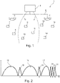
- an electronic price display system is shown as a system 1 according to the invention for communicating according to a time slot communication method, which is installed in the premises of a retail establishment is installed. For reasons of clarity, the figures do not show the premises and their furnishings.
- the system 1 has a server 2, a first and a second communication station 3 and 4 (referred to below as the station for short), and a number of eight radio tags 7-14 (referred to below as ESL for Electronic Shelf Label).
- the server is housed in offices and is connected to stations 3 and 4 via a wired communication line (LAN). Stations 3 and 4 are in contact with the ESL 7-14 via radio signals. Stations 3 and 4 are mounted in different positions on the ceiling in a sales room.
- the ESL 7 - 14 are attached to shelves corresponding to products for which the ESL 7 - 14 is used to display price and product information.
- the product information is transmitted from the server 2 to the stations 3, 4 and from there it is communicated individually to the individual ESLs 7-14.
- Each station 3, 4 covers a radio area, with a first radio area limit 5 of the station 3 and a second radio area limit 6 of the station 4 being indicated in some areas.
- the radio areas have an overlap area in which the ESL 9 - 11 are located.
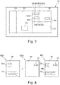
- Each station 3 or 4 knows the radio channels with the channel numbers 3, 5, 8, 9 and 10 preferred for the operation of the system 1. This is in the figure 2 shown, in which different frequency bands 15-22 are represented by channel numbers K wind. Frequency bands 15, 16 and 17 are available for operating a conventional WLAN. The frequency bands 18, 19, 20 - 22 preferred for the operation of system 1 correspond to channel numbers 3, 5, 8 - 10 and do not overlap with the WLAN frequency bands 15 - 17.
- Station 3 automatically selected the radio channel with channel number 3 , because this was the first to be checked to see whether it was already occupied by another station.
- Station 4 automatically selected the radio channel with channel number 5 because when it checked for free radio channels, it found that the radio channel with channel number 3 was already occupied and that the next free radio channel was channel number 5 has been identified. However, the assignment of the radio channels can also be fixed.
- the ESL 7 - 14 As soon as the ESL 7 - 14 are brought into the respective radio range of the station 3 or 4, they find that in one or more radio channels Radio signals of the applicable stations 3 and 4 exist.
- the ESL 7 and 8 establish a connection to the first station 3.
- the ESL 12 - 14 establish a connection to the second station 4.
- For the ESL 9 - 11 it is determined that both stations 3 and 4 are available for all of them.
- Each ESL 9 - 10 now checks the reception quality of the radio signals received from the respective station 3, 4 and decides on the station 3 or 4 for which the best reception quality was determined in order to establish a connection with it in the respective radio channel (channel number 3 or 5).
- this decision-making process can also be carried out by stations 3 and 4, with the stations checking the respective reception quality of a communication with the ESLs 9-11 and mutually agreeing on which of them will establish a connection with which of the ESLs 9-11 , because there are 9 - 11 more favorable communication conditions for the respective ESL.
- the decision-making regarding the association between the ESL 9 - 11 and the stations 3 , 4 can also be outsourced to the server 2 , since it is in contact with the stations 3 , 4 .
- radio channels are first selected (also referred to as "channel scan"), if necessary an evaluation of the reception quality on the respective radio channel is carried out and then unique hardware addresses of the ESL 7 -14 to the station 3, 4 selected for communication. Thus each station 3, 4 knows the ESL 7-14 assigned to it.
- each ESL 7 - 14 is assigned to exactly one product.
- the server gains knowledge of where in the salesroom, on which shelf and on which shelf position the respective ESL 7 - 14 is (or should be) because it also knows the corresponding position of the products, which is represented with the aid of a planogram.
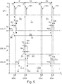
- the ESL 7 has a radio module 24, a processor 25 for processing data, for controlling operating states and for providing functions, a memory 26 for storing data and programs, and a display 27 realized in energy-saving electronic ink technology see full ad of the product information.
- the radio module 24 is used for radio-based communication with the stations 3 and 4, with reception data being generated from received radio signals and being transferred to the processor 25, or transmission data transferred from the processor 25 being converted into radio signals.
- the data stored in memory 26 may be associated with both processor 25 and display 27.
- the selected representation also does not distinguish what type of memory (ROM, EEPROM, RAM, etc.) is involved or how the memory 26 is logically or physically assigned to the processor 25 and/or the display 27. Connections such as signal and/or data lines between the function blocks 24 - 27 and the energy store (in the present case a battery) are also not shown in the selected representation.
- image data BD for generating an image using the display 27, the image data BD specifying a first image plane of the image with first-level data ED1 and a second image plane of the image with second-level data ED2, hardware Address data HAD for specifying the hardware address of the ESL and parameter data PD relating to the parameterization of the time slot communication method are stored. It should be mentioned at this point that other image planes can also be present.
- the hardware address data HAD comprises four bytes B3, B2, B1, B0, B0 being the least significant byte of the hardware address.
- Both the various plane data ED1 and ED2 are combined in the ESL 7 to form the overall image.
- Both the first and second level data ED1, ED2 represent image information about each pixel.
- specific image information is defined as "transparent", “background” or “background color” for both image planes.
- the individual image planes can therefore be superimposed pixel by pixel, i.e. the overall image can be built up by superimposing the image contents to identical coordinates of the pixels from different image planes.
- the images are in bitmap format, but they can also be in other formats such as JPG, etc.
- a first image level 28 represented by the first level data ED1 essentially contains static image information 29 on a product, with this static image information is only changed if the ESL 7 is assigned to another product.
- the static image information 29 relates to descriptive text about the product, for example. All other image areas are defined as "transparent”.
- a second image level 30, represented by the second level data ED2, essentially contains dynamic image information 31, which changes relatively often in comparison to the static image information, such as daily or several times a day or weekly.
- the dynamic image information 31 relates, for example, to the price of the product or also information on the validity of an offer, such as, for example, the start date and end date or times or other conditions that are linked to the offer.
- the entire image data BD can be received in compressed form at once, decompressed and stored in the memory 26. This can happen, for example, when the overall image is transmitted for the first time. However, the process is relatively lengthy and consequently causes a relatively high energy requirement. If the image once exists in the ESL 7, a partial update of the image is more efficient because this can be done in a more energy-efficient manner.
- the ESL 7 can receive the image plane to be updated (e.g. the second image plane 30) separately from the other image plane already stored in the memory 26 (e.g. the first image plane 28), decompress it and store it in the memory 26. Thereafter, the newly created second level data ED2 is accessed internally (switched from one memory page to another memory page) to rebuild the overall image 32 .
- the ESL 7 also has a timing stage 33 which can be implemented as an independent hardware component or at least partially with the aid of the processor 25 . It generates a time base typical of the ESL and uses this time base to control the timing (entering and leaving) of the states of the ESL 7. The timing is controlled, for example, with Using timing parameters inherently known to the timing circuit and/or provided by the processor.
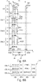
- the top sequence of states shows the states of stage 3 countersigned by ST. N time slots Z1 . . . ZN (eg 256) with an identical time slot duration DS (eg approx. 58 milliseconds) are available during a time slot cycle duration DC (eg 15 seconds).
- stage 3 changes between a transmission state T and an idle state R.
- the transmission state T is always assumed at the beginning of a time slot Z1 ... ZN and for a synchronization data signal duration DSD (or transmission duration DSD of the synchronization Data signal SD) maintained in order to send the respective applicable time slot symbol ZS1, ZS2, ... ZSN with the respective synchronization data signal SD.
- the consecutive number of the respective time slot Z1 ... ZN in the order in which the time slots Z1 ... ZN occur is used as the respective time slot cycle symbol ZS1 ... ZSN. Consequently, the first time slot Z1 in hexadecimal notation (identified by "Hex") with the time slot symbol Hex 00, the second time slot Z2 with the time slot symbol Hex 01 etc. and the last time slot ZN (in the present example the two hundred and fifty-sixth time slot Z256 with the time slot symbol Hex FF marked.
- the hardware addresses of the ESL 7 - 9 would be unchangeable in a real operation of the system 1.
- the ESLs of the system 1 will sometimes differ from figure to figure Hardware addresses assigned or even single or multiple ESL not included in the discussion.
- FIG 8 is the hardware address of the first ESL 7 hex B2:00:01:00, the second ESL 8 hex B2:00:01:01, the third ESL 9 hex B2:00:02:01 and the fourth ESL 10 hex B2 :00:03:01.
- the least significant byte B0 in the respective ESL 7-10 is used to identify a time slot that occurs as part of the time slot communication method and that is intended for the respective ESL 7-10.
- the remaining three bytes B1 - B3 of the hardware address are used to individually address an ESL 7 - 10 in the time slot Z1 ... ZN specified for the respective ESL.
- the first ESL 7 is in the more synchronous state. It wakes up from its sleep state S at a first wake-up time TA1 and changes to its ready-to-receive active state E with a relatively short lead time DV before an expected occurrence of a synchronization data signal SD, receives the synchronization data signal SD during a reception period DE with the first timeslot symbol ZS1 (Hex 00), determines by comparing the least significant byte B0 of its hardware address (Hex 00) with the received timeslot symbol ZS1 that the first timeslot Z1 intended for the first ESL 7 is indicated (correspondence of the bytes to be compared: B0 of the hardware address and first time slot symbol ZS1), retains the parameters of the time control stage 33 used to control the wake-up for waking up in the subsequent time slot cycle for the purpose of defining the new wake-up time and switches back to the sleep state S with a relatively short follow-up time DN, order after the expiry of the provided Sleep state dwell time DR
- the third ESL 9 is in the asynchronous state before a synchronization point in time TSY, which is indicated by the broken line of the arrow 34 running parallel to the time axis. It wakes up at a randomly selected first wake-up time TA1 and changes from its sleep state S to the active state E ready to receive and waits in this state until the next occurrence of the synchronization data signal SD is received, with the second time slot symbol ZS2 ( Hex 01) is received.
- the third ESL 9 recognizes from the least significant byte B0 (Hex 00) of its hardware address that the specific time slot in the present time slot cycle already belongs to the past and consequently the next time slot with the time slot symbol Hex 00 is only to be expected in the next time slot cycle , and calculates that the currently recognized time slot Z2 is one time slot next to its original time slot Z1, which is referred to below as the time slot difference.
- the time control stage 33 is now programmed so that the new wake-up time TA2 lies before the occurrence of the first time slot Z1 of the subsequent time slot cycle, as in the case of an ESL in the synchronous state with said lead time DV.
- the waiting time DSA in the sleep state S is calculated as follows: sleep state dwell time DR (in the synchronous state) minus the time slot duration DS multiplied by the time slot difference (value 1 in the present case).
- the third ESL 9 is thus again in the synchronous state, which is indicated by the arrow 35 with a solid line, and changes from the active state E to the sleep state S, after the dwell time DAS has elapsed at the new wake-up time TA2 Active state E to switch.
- a “PING” command is transmitted to the first ESL 7, a “PING” command is likewise transmitted to the second ESL 8, and a “SWPAG2” command is transmitted to the third ESL 9.
- These commands are single time slot commands which are processed immediately after their decoding in the relevant ESL 7 - 9 with a negligible expenditure of time.
- the two "PING" commands are used to test whether the addressed ESL 7, 8 reports back with confirmation data ACD, ie whether it exists or whether it reacts at all and is synchronized.
- the "SWAPG2" command causes the third ESL 9 to switch from a (first) current memory page (or memory page) to a second memory page (or memory page) in order, for example, to change the image to be displayed using the display 27, just like this in connection with the figure 4 was discussed.
- the synchronization data signal SD is used to transmit a confirmation time for the first ESL 7 by specifying a first idle period DR1, for the second ESL 8 by specifying a second idle period DR2 and for the third ESL 9 by specifying a third idle period DR3.
- the reference point for the three idle periods DR1 - DR3 is always the end of the reception period DE.
- the data structure transmitted using the synchronization data signal SD at the beginning of the first time slot Z1 is in FIG Figure 6B visualized.
- maximum time periods for responses can also be specified, which result from the sum of the respective idle time periods DR1-DR3 and the time period for delivering the confirmation data ACD.
- FIG. 7A shows the processing of a multiple time slot command, in which the first ESL 7 splits overall data (e.g. relating to an entire image to be displayed or just one image plane of the image) over three adjacent time slots Z1 - Z3 into three data packets DAT1 - DAT3 from station 3 receives.
- overall data e.g. relating to an entire image to be displayed or just one image plane of the image
- the first ESL 7 recognizes its synchronous state and that it is individually addressed (addressees Hex B2:00:01), receives and decodes a "DATA_INIT" command with which it receives the three data packets DAT1 - DAT3 is commanded in said time slots Z1 - Z3, and at the end of the receiving period DE goes into the sleep state S for a first waiting period DW1, the first waiting period DW1 ending at the end of the first half of the time slot period DS.
- the station 3 At the beginning of the second part 37 of the first time slot Z1, the station 3 goes into its transmit state T and the first ESL 7 into its ready-to-receive active state E, so that it receives the first data packet DAT1 during a data transmission period DT. It then confirms successful reception with the aid of partial confirmation data ACD1 during a confirmation period DA, during which station 3 is also in reception state E.
- the confirmation period DA ends before the end of the first time slot Z1.
- the first ESL 7 After the confirmation period DA has elapsed, the first ESL 7 remains in the sleep state S for a second waiting period DW2, which lasts until the end of the first part 36 of the second (subsequent) time slot Z2.
- the first ESL 7 recognizes its synchronous status (least significant byte B0 of the hardware address is hex 00) and that it is individually addressed (address data hex B2:00:01), receives and decodes a "DATA_INIT "Command with which it is ordered to receive three data packets DAT1 - DAT3 in the time slots Z1 - Z3.
- the data structure transmitted using the synchronization data signal SD at the beginning of the first time slot Z1 is in FIG Figure 8B visualized.
- the data transfer from station 3 to the first ESL 7 is analogous to the discussion in FIG Figure 7A .
- the three remaining ESLs 8 - 10 recognize that they are synchronous because the second time slot symbol Z2 indicates the time slot intended for them (least significant byte B0 of the hardware address is hex 01 for all three ESLs 8 - 10).
- Checking the address data AD shows that each ESL 8 - 10 is addressed individually (existence of the remaining three bytes B1 - B3 of the respective hardware address in the address data AD), the commands intended for the respective ESL 8 - 10 are decoded (In this case, three "PING" commands) and executed immediately, and the individual confirmation data ACD after an elapse of the individual idle time periods DR1 - DR3 to the station 3, as is the case for the Figure 6A was discussed.
- the data structure transmitted using the synchronization data signal SD at the start of the second time slot Z2 is in FIG Figure 8C visualized.
- the three single-timeslot commands and the multiple-timeslot command in the second timeslot T2 are treated more or less simultaneously in relation to the "timeslot" time unit, since the first part 36 for the single-timeslot commands and the second part for the multiple-timeslot command 37 of the second time slot Z2 is reserved for the data communication required in each case.
- the assignment of the respective command type to the parts of the time slot 36, 37 can also be reversed.
Landscapes
- Engineering & Computer Science (AREA)
- Physics & Mathematics (AREA)
- Health & Medical Sciences (AREA)
- Toxicology (AREA)
- Business, Economics & Management (AREA)
- General Physics & Mathematics (AREA)
- Theoretical Computer Science (AREA)
- Strategic Management (AREA)
- Finance (AREA)
- Accounting & Taxation (AREA)
- Development Economics (AREA)
- Computer Networks & Wireless Communication (AREA)
- Computer Vision & Pattern Recognition (AREA)
- General Health & Medical Sciences (AREA)
- Electromagnetism (AREA)
- Artificial Intelligence (AREA)
- Marketing (AREA)
- Game Theory and Decision Science (AREA)
- Entrepreneurship & Innovation (AREA)
- Economics (AREA)
- General Business, Economics & Management (AREA)
- Signal Processing (AREA)
- Mobile Radio Communication Systems (AREA)
- Time-Division Multiplex Systems (AREA)
- Near-Field Transmission Systems (AREA)
Description
Die Erfindung betrifft ein System zur Kommunikation mit einem Funk-Tag.The invention relates to a system for communicating with a radio tag.
Ein eingangs erwähntes System ist beispielsweise aus der
Die Erfindung hat sich die Aufgabe gestellt, ein System bereitzustellen, sodass die eingangs erörterten Probleme vermieden sind.The object of the invention is to provide a system so that the problems discussed above are avoided.
Diese Aufgabe wird durch ein System gemäß Anspruch 1 gelöst.This object is solved by a system according to
Der Gegenstand der Erfindung ist daher ein System, aufweisend eine Kommunikationsstation zum Kommunizieren mit einer Anzahl von Funk-Tags mit Hilfe eines Zeitschlitzkommunikationsverfahrens, bei dem in sich wiederholender Folge eine Anzahl von Zeitschlitzen pro Zeitschlitzzyklus zur Kommunikation bereitstehen und jeder Zeitschlitz durch ein eindeutiges Zeitschlitzsymbol gekennzeichnet ist, wobei die Kommunikationsstation dazu ausgebildet ist, für den momentan vorliegenden Zeitschlitz ein Synchronisations-Datensignal aufweisend das Zeitschlitzsymbol auszusenden, und wobei ein Funk-Tag ausgebildet ist zum Wechseln von einem Schlaf-Zustand in einen Aktiv-Zustand zu einem Aufwachzeitpunkt, und zum Empfangen des Synchronisations-Datensignals im Aktiv-Zustand, und, wenn das empfangene Zeitschlitzsymbol einen für ihn bestimmten Zeitschlitz anzeigt, zum Definieren eines zu dem nächsten Auftreten des für ihn bestimmten Zeitschlitz korrespondierenden neuen Aufwachzeitpunkts in einem auf den momentan vorliegenden Zeitschlitzzyklus folgenden Zeitschlitzzyklus, wobei das System aufweist eine Mehrzahl von Kommunikationsstationen und eine Mehrzahl von Funk-Tags und eine Datenverarbeitungseinrichtung, die dazu ausgebildet ist, einen Funk-Tag dazu zu veranlassen, eine bestehende Verbindung mit einer der Kommunikationsstationen zu beenden und eine Verbindung mit einer anderen Kommunikationsstation einzugehen.The subject of the invention is therefore a system having a communication station for communicating with a number of radio tags using a time slot communication method in which a number of time slots per time slot cycle are available for communication in a repetitive sequence and each time slot is identified by a unique time slot symbol , wherein the communication station is designed to transmit a synchronization data signal for the currently available time slot, having the time slot symbol, and wherein a radio tag is designed to change from a sleep state to an active state at a wake-up time, and to receive the Synchronization data signal in the active state, and, if the received time slot symbol indicates a time slot intended for it, for defining a new wake-up time corresponding to the next occurrence of the time slot intended for it in an on the mome ntan present time slot cycle following time slot cycle, the system having a plurality of communication stations and a plurality of radio tags and a data processing device which is designed to cause a radio tag to end an existing connection with one of the communication stations and a connection with another communication station.
Mit den erfindungsgemäßen Maßnahmen geht der Vorteil einher, dass ein Synchronismus zwischen der Kommunikationsstation und einem Funk-Tag auf möglichst einfache und trotzdem äußerst robuste Weise erkannt, beibehalten und während des Betriebs des Systems gewährleistet ist. Im Unterschied zu bekannten Maßnahmen müssen nun nicht mehr alle Funk-Tags gleichzeitig zu einem bestimmten Zeitpunkt in ihrem Aktiv-Zustand sein, um mit dem durch die Kommunikationsstation definierten Zeitraster des Zeitschlitzkommunikationsverfahren synchron zu bleiben. Ebenso kann auf das Empfangen und Auswerten von Daten verzichtet werden, die eine zeitliche Abweichung von einem Referenzzeitpunkt anzeigen, was sich als sehr aufwändig im Hinblick auf das Verarbeiten dieser Daten als auch auf das Datenaufkommen bei der Kommunikation mit der Kommunikationsstation erwiesen hat. Gemäß der Erfindung reicht es aus, dass jeder Funk-Tag, der sich an der Kommunikation mit der Kommunikationsstation beteiligt, über das Zeitschlitzsymbol Bescheid weiß, welches den für ihn bestimmten Zeitschlitz anzeigt. Jeder der Funk-Tags orientiert sich also individuell an dem Auftreten eines für ihn relevanten Zeitschlitzsymbols, identifiziert das für ihn relevante Zeitschlitzsymbol und definiert seinen nächsten Aufwachzeitpunkt, mit dem durch die Kommunikationsstation vorgegebenen Timing des Zeitschlitzkommunikationsverfahrens. Dabei reicht es völlig aus, dass das Zeitschlitzsymbol den jeweiligen Zeitschlitz eindeutig identifiziert, z.B. mit einer für jeden Zeitschlitz individuellen Zeitschlitzkennung. Weitere Informationen kodiert in das Synchronisations-Datensignal, so wie in Bezug auf die bekannten Maßnahmen erörtert, sind nicht nötig, um einen Funk-Tag synchron mit der Kommunikationsstation zu betreiben. Der Funk-Tag stellt seinen Synchronismus mit der Kommunikationsstation alleine durch den Umstand des Erkennens des Zeitschlitzsymbols fest, das zu dem von ihm erwarteten Zeitpunkt bzw. in einem Erwartungszeitfenster auftritt und den für ihn bestimmten Zeitschlitz anzeigt.The measures according to the invention have the advantage that synchronism between the communication station and a radio tag is identified in the simplest possible yet extremely robust manner, maintained and guaranteed during operation of the system. In contrast to known measures, it is now no longer necessary for all radio tags to be in their active state at the same time at a specific point in time in order to remain synchronous with the time grid of the time slot communication method defined by the communication station. Likewise, there is no need to receive and evaluate data that indicate a time deviation from a reference point in time, which has proven to be very complex with regard to the processing of this data and the data volume during communication with the communication station. According to the invention, it is sufficient that each radio tag that takes part in the communication with of the communication station involved, knows about the time slot symbol, which indicates the time slot intended for him. Each of the radio tags is oriented individually to the occurrence of a time slot symbol relevant to it, identifies the time slot symbol relevant to it and defines its next wake-up time, with which the Communication station predetermined timing of the time slot communication method. In this case, it is entirely sufficient for the time slot symbol to uniquely identify the respective time slot, for example with a time slot identifier that is individual to each time slot. Further information encoded in the synchronization data signal, as discussed in relation to the known measures, is not necessary to operate a radio tag synchronously with the communication station. The radio tag establishes its synchronicity with the communication station simply by recognizing the time slot symbol which occurs at the time it expects or in an expected time window and which indicates the time slot intended for it.
Nachdem der Funk-Tag seinen Synchronismus wie zuvor erörtert festgestellt hat, reicht es grundsätzlich aus, wenn er wieder in den Schlaf-Zustand wechselt, weil der nächste Aufwachzeitpunkt automatisch durch den ihm bekannten Zeitraster des Zeitschlitzkommunikationsverfahrens bekannt ist. Das Definieren des neuen Aufwachzeitpunktes kann sich somit darauf beschränken, dass eine z.B. Zeitsteuerstufe (z.B. ein Timer) des Funk-Tags mit den bereits zuvor zum Wechseln vom Schlaf-Zustand in den Aktiv-Zustand benutzen Timing-Parameter neu gestartet wird. Danach kann der Funk-Tag wieder in den Schlaf-Zustand wechseln und dort verharren, bis dass ausgelöst durch die Zeitsteuerung wieder ein Aufwachen und Wechseln von dem Schlaf-Zustand in den Aktiv-Zustand zu dem neuen Aufwachzeitpunkt in dem nächsten Zeitschlitzzyklus durchgeführt wird. Der Funk-Tag muss jedoch nicht zwingend für den Rest des für ihn bestimmten Zeitschlitzes im Schlaf-Zustand verharren, sondern kann auch während des Zeitschlitzes oder auch des Zeitschlitzzyklus weitere Aufgaben in einem Aktiv-Zustand bearbeiten. Die zuvor erörterte Zeitsteuerung arbeitet dann im Hintergrund unabhängig von seinen weiteren Aktivitäten. Das Definieren des neuen Aufwachzeitpunktes kann durch die Bestimmung einer absoluten oder relativen Zeitangabe erfolgen, wie z.B. relativ zum Zeitpunkt des Auftretens des Synchronisations-Datensignals oder relativ zum Zeitpunkt, zu dem nach dem Aktiv-Zustand wieder der Schlaf-Zustand eingenommen wird oder auch relativ zum Zeitpunkt zu dem das Ende des Synchronisations-Datensignals eintritt. Das Definieren des neuen Aufwachzeitpunktes kann jedoch auch so verstanden werden, dass die Dauer des nach dem Aktiv-Zustand, in dem das Zeitschlitzsymbol empfange wurde, anschließenden Schlaf-Zustands oder auch die Summe der Dauer aus Schlaf-Zustand und Aktiv-Zustand oder auch die Summe der Dauer mehrerer solcher Zustandsfolgen den neuen Aufwachzeitpunkt bestimmt. Da jeder Funk-Tag seine eigene Zeitsteuerstufe betreibt und exemplarische Streuungen des Verhaltes der jeweiligen elektronischen Komponenten nicht auszuschließen sind, kann das Definieren des neuen Aufwachzeitpunktes auch eine Kompensation einer für jeden Funk-Tag individuell vorliegenden Drift seiner Zeitbasis beinhalten. Zu diesem Zweck kann beispielsweise im Funk-Tag eine Zeitdifferenz zwischen dem erwarteten Auftreten des Synchronisations-Datensignal mit dem Zeitschlitzsymbol, das den für den jeweiligen Funk-Tag bestimmten Zeitschlitz anzeigt, und dem tatsächlichen Auftreten gemessen werden und bei der Zeitsteuerstufe zur Korrektur ihres Timings berücksichtigt werden. Die Kompensation kommt jedoch nur bei Festgestelltem Synchronismus zum Einsatz. Wurde jedoch an Stelle des erwarteten Zeitschlitzsymbols ein anderes Zeitschlitzsymbol empfangen, liegt kein Synchronismus vor und der Funk-Tag müsste eine Neu-Synchronisierung durchführen, worauf nachfolgend noch eingegangen ist.After the radio tag has established its synchronicity as discussed above, it is basically sufficient if it changes back to the sleep state because the next wake-up time is automatically known from the time grid of the time slot communication method known to it. Defining the new wake-up time can thus be limited to restarting a time control stage (eg a timer) of the radio tag with the timing parameters already used to switch from the sleep state to the active state. The radio tag can then switch back to the sleep state and remain there until, triggered by the time control, it wakes up again and changes from the sleep state to the active state at the new wake-up time in the next time slot cycle. However, the radio tag does not necessarily have to remain in the sleep state for the remainder of the time slot intended for it, but can also process other tasks in an active state during the time slot or also the time slot cycle. The timing previously discussed then operates in the background independently of its other activities. The new wake-up time can be defined by determining an absolute or relative time specification, such as relative to the time the synchronization data signal occurs or relative to the time at which the sleep state is resumed after the active state or also relative to the Time at which the end of the synchronization data signal occurs. However, the definition of the new wake-up time can also be understood in such a way that the duration of the sleep state following the active state in which the time slot symbol was received, or also the sum of the duration of the sleep state and active state or also the sum of the duration of several such state sequences determines the new wake-up time. Since each radio tag operates its own time control stage and exemplary scattering of the behavior of the respective electronic components cannot be ruled out, defining the new wake-up time can also include compensation for a drift in its time base that is individually present for each radio tag. For this purpose, a time difference between the expected occurrence of the synchronization data signal with the time slot symbol, which indicates the specific time slot for the respective radio tag, and the actual occurrence can be measured in the radio tag, for example, and taken into account in the time control stage to correct its timing will. However, the compensation is only used when synchronism is detected. However, if a different time slot symbol was received instead of the expected time slot symbol, there is no synchronism and the radio tag would have to carry out a new synchronization, which will be discussed below.
Bei dem Zeitschlitzkommunikationsverfahren kommen z.B. innerhalb von n Sekunden, z.B. 15 Sekunden, m Zeitschlitze, z.B. 255 Zeitschlitze, zum Einsatz. Die n Sekunden bilden einen Zeitschlitzzyklus. In diesem Zeitschlitzkommunikationsverfahren stehen also m Zeitschlitze innerhalb eines Zeitschlitzzyklus für eine Kommunikation mit den Funk-Tags zur Verfügung. Jeder der Funk-Tags kann einem der Zeitschlitze zugeordnet sein, wobei einem bestimmten Zeitschlitz auch mehrere Funk-Tags zugeordnet sein können.For example, in the time slot communication method, m time slots, for example 255 time slots, are used within n seconds, for example 15 seconds. The n seconds form a time slot cycle. In this time slot communication method, m time slots are therefore available within a time slot cycle for communication with the radio tags. Each of the radio tags can be assigned to one of the time slots, it also being possible for a number of radio tags to be assigned to a specific time slot.
Ein Funk-Tag weist im Wesentlichen eine Funk-Kommunikationsstufe, auch Transceiver genannt, und eine damit zusammenwirkende Logikstufe auf, die logische Funktion eines Tag bereitstellt. Die Logikstufe kann z.B. vollständig durch Hardware realisiert sein oder einen Mikroprozessor und Speicherbausteine oder einen Mikrokontroller mit integrierten Speicherbausteinen aufweisen, sodass in den Speicherbausteinen gespeicherte Software abarbeitbar ist. Ein Tag kann mit Hilfe seiner Funk-Kommunikationsstufe ein Funk-Signal empfangen, in dem Funk-Signal enthaltene Empfangsdaten mit Hilfe der Logikstufe verarbeiten und gegebenenfalls mit Hilfe der Logikstufe Antwortdaten generieren und diese über die Funk-Kommunikationsstufe wieder als ein Funk-Signal abgeben. Die Funk-Kommunikationsstufe weist Mittel zur Funkkommunikation und zur Konvertierung von analogen Signalen in digitale Signale und umgekehrt auf.A radio tag essentially has a radio communication stage, also called a transceiver, and a logic stage that interacts with it and provides the logical function of a tag. The logic stage can, for example, be implemented entirely by hardware or have a microprocessor and memory chips or a microcontroller with integrated memory chips, so that software stored in the memory chips can be processed. A tag can use its radio communication level to receive a radio signal, process the received data contained in the radio signal using the logic level and, if necessary, use the logic level to generate response data and emit this again as a radio signal via the radio communication level. The radio communication stage has means for radio communication and for converting analogue signals into digital signals and vice versa.
Ein solcher Funk-Tag kann zu seiner Energieversorgung einen Energiespeicher, wie z.B. eine Batterie oder ein Solarpaneel gekoppelt mit einer aufladbaren Batterie aufweisen. Um möglichst energieeffizient zu arbeiten, weisen die Funk-Tags verschiedene Betriebs-Zustände auf. Ein Funk-Tag weist in dem Aktiv-Zustand einen relativ hohen Energieverbrauch auf. Der Aktiv-Zustand liegt z.B. beim ein Senden oder Empfangen von Daten, beim Display-Update, beim Batteriespannungsmessen usw. vor. In dem Schlaf-Zustand liegt dagegen ein relativ niedriger Energieverbrauch vor. Bevorzugt werden so viele elektronische Komponenten wie möglich von der Stromversorgung getrennt bzw. abgeschattet oder zumindest in einem Modus mit möglichst geringem Energiebedarf betrieben. Der Aktiv-Zustand liegt vorwiegend in dem für den Funk-Tag bestimmten Zeitschlitz zur Kommunikation mit der Kommunikationsstation vor. In dem Aktiv-Zustand weist der Funk-Tag z.B. eine Empfangsbereitschaft auf, um Befehle und gegebenenfalls auch Empfangs-Daten von der Kommunikationsstation zu empfangen und mit Hilfe der Logikstufe zu verarbeiten. Im Aktiv-Zustand können auch mit Hilfe der Logikstufe Sende-Daten generiert und an die Kommunikationsstation kommuniziert werden. Außerhalb des für den Funk-Tag bestimmten Zeitschlitzes wird der Funk-Tag vorwiegend in dem energiesparenden Schlaf-Zustand betrieben. In dem Schlaf-Zustand führt die Logikstufe bzw. die Zeitsteuerstufe nur jene Aktivitäten durch, die für das Timing zum rechtzeitigen Aufwachen nötig sind, damit der Funk-Tag zum nächsten für ihn bestimmten Zeitschlitz zum Empfang des Synchronisations-Datensignals und / oder zur Kommunikation mit der Kommunikationsstation bereit ist. Um energieeffizient zu arbeiten und damit eine möglichst lange Lebensdauer des Funk-Tags zu erreichen besteht die grundlegende Betriebsstrategie darin, den synchronen Funk-Tag so lange wie möglich im Schlaf-Zustand zu halten und nur dann, wenn unbedingt nötig, zwecks Datenübertragung mit der Kommunikationsstation für eine möglichst kurze Zeitspanne im Aktiv-Zustand zu betreiben.Such a radio tag can have an energy store, such as a battery or a solar panel coupled with a chargeable battery, for its energy supply. In order to work as energy-efficiently as possible, the radio tags have different operating states. A radio tag has a relatively high energy consumption in the active state. The active state is present, for example, when data is sent or received, when the display is updated, when the battery voltage is measured, etc. In the sleep state, on the other hand, there is relatively low energy consumption. As many electronic components as possible are preferably disconnected from the power supply or shaded or at least operated in a mode with the lowest possible energy requirement. The active state is primarily present in the time slot intended for the radio tag for communication with the communication station. In the active state, the radio tag is ready to receive, for example, in order to receive commands and possibly also received data from the communication station and to process them using the logic stage. In the active state, transmission data can also be generated and communicated to the communication station with the aid of the logic stage. Outside the time slot intended for the radio tag, the radio tag is mainly operated in the energy-saving sleep mode. In the sleep state, the logic stage or the time control stage only carries out those activities that are necessary for the timing to wake up in time, so that the radio tag can go to the next time slot intended for it to receive the synchronization data signal and / or to communicate with the communication station is ready. In order to work energy-efficiently and thus achieve the longest possible service life of the radio tag, the basic operating strategy is to keep the synchronous radio tag in the sleep state for as long as possible and only when absolutely necessary for data transmission with the communication station to operate in the active state for as short a period of time as possible.
Die Kommunikationsstation kann eine für sich autonome Einrichtung mit Serverfunktionalität sein. Bevorzugt, wird die Kommunikationsstation eine Schnittstelle zwischen einer kabelgebundenen Kommunikation mit z.B. einer Datenverarbeitungseinrichtung (z.B. einem Server) und einer kabellosen, funkbasierten Kommunikation mit den Funk-Tags bilden.The communication station can be an autonomous device with server functionality. Preferably, the communication station is an interface between a wired communication with, for example, a Form data processing device (e.g. a server) and a wireless, radio-based communication with the radio tags.
Um für die Kommunikation mit der Kommunikationsstation verfügbar zu sein, können sich die Funk-Tags zunächst bei der Kommunikationsstation registrieren bzw. ihr zugeordnet werden.In order to be available for communication with the communication station, the radio tags can first register with the communication station or be assigned to it.
Weitere, besonders vorteilhafte Ausgestaltungen und Weiterbildungen der Erfindung ergeben sich aus den abhängigen Ansprüchen sowie der nachfolgenden Beschreibung.Further, particularly advantageous configurations and developments of the invention result from the dependent claims and the following description.
Mit den Maßnahmen gemäß der Erfindung lässt sich nicht nur der Synchronismus zwischen der Kommunikationsstation und einem Funk-Tag auf einfache Weise sicherstellen, sondern auch ein Funk-Tag, der in einen asynchronen Zustand eingetreten ist, unproblematisch wieder in das zeitliche Schema das Zeitschlitzkommunikationsverfahrens zurückführen, also wieder synchronisieren. Zu diesem Zweck wechselt ein solcher asynchroner Funk-Tag nicht periodisch, so wie dies im synchronen Zustand der Fall wäre, sondern z.B. zu einem beliebigen Zeitpunkt ein einziges Mal von seinem Schlaf-Zustand in seinen Aktiv-Zustand und verharrt in diesem Aktiv-Zustand in der Empfangsbereitschaft. Wenn in einer bestimmten Zeitspanne wie z.B. einer Zeitschlitzdauer nichts empfangen wurde, wechselt er wieder in den Schlaf-Zustand und wiederholt zu einem andern Zeitpunkt den Empfangsversuch. Sobald ein Synchronisations-Datensignal empfangen wird, wird das Zeitschlitzsymbol ausgewertet. Das dabei empfangene Zeitschlitzsymbol zeigt mit höchster Wahrscheinlichkeit einen für ihn nicht bestimmten Zeitschlitz an, was vom Funk-Tag autonom festgestellt wird. Der Funk-Tag kennt die Systematik des Auftretens der Zeitschlitzsymbole und kann nach Auswertung des empfangenen Zeitschlitzsymbols selbstständig entscheiden, ob er noch in dem vorliegenden Zeitschlitzzyklus (erster Fall) oder erst im darauffolgenden Zeitschlitzzyklus (zweiter Fall) mit dem für ihn bestimmten Zeitschlitz rechnen kann. Für den ersten Fall ist der Funk-Tag zum Definieren eines zu dem nächsten Auftreten des für ihn bestimmten Zeitschlitz korrespondierenden neuen Aufwachzeitpunkts in dem momentanen vorliegenden Zeitschlitzzyklus ausgebildet. Der Funk-Tag stellte durch Auswertung des empfangenen Zeitschlitzsymbols und unter Kenntnis der Systematik des Auftretens der Zeitschlitzsymbole fest, dass der für ihn bestimmte Zeitschlitz noch in dem momentan vorliegenden Zeitschlitzzyklus auftreten wird. Für den zweiten Fall ist der Funk-Tag zum Definieren eines zu dem nächsten Auftreten des für ihn bestimmten Zeitschlitz korrespondierenden neuen Aufwachzeitpunkts in jenem dem momentan vorliegenden Zeitschlitzzyklus folgenden Zeitschlitzzyklus ausgebildet. Der Funk-Tag stellte durch Auswertung des empfangenen Zeitschlitzsymbols und unter Kenntnis der Systematik des Auftretens der Zeitschlitzsymbole fest, dass der für ihn bestimmte Zeitschlitz in dem momentan vorliegenden Zeitschlitzzyklus nicht mehr auftreten wird, weil er in diesem Zeitschlitzzyklus bereits in der Vergangenheit auftrat. Wie einleitend zum synchronen Zustand erörtert, kommt auch für diese Art der Definition des neuen Aufwachzeitpunkts besagte Zeitsteuerung zum Einsatz, wobei die Zeitsteuerung nun mit jenem Timing-Parameter betrieben wird, mit dem der erwünschte Eintritt in den synchronen Zustand erreicht wird. Der zu wählende Timing-Parameter ergibt sich für den Funk-Tag aus der inhärenten Kenntnis des zur Anwendung kommenden Zeitschlitzkommunikationsverfahrens, er wird also von der Logikstufe bestimmt.With the measures according to the invention, not only can the synchronism between the communication station and a radio tag be ensured in a simple manner, but also a radio tag that has entered an asynchronous state can be easily returned to the time scheme of the time slot communication method. So sync again. For this purpose, such an asynchronous radio tag does not change periodically, as would be the case in the synchronous state, but instead changes from its sleep state to its active state once at any time and remains in this active state the willingness to receive. If nothing is received within a certain period of time, such as a time slot, it switches back to the sleep state and tries to receive again at a different time. As soon as a synchronization data signal is received, the time slot symbol is evaluated. The time slot symbol received indicates with the highest probability a time slot not intended for it, which is determined autonomously by the radio tag. The radio tag knows the systematics of the occurrence of the time slot symbols and, after evaluating the received time slot symbol, can independently decide whether it can still calculate with the time slot intended for it in the present time slot cycle (first case) or only in the following time slot cycle (second case). In the first case, the radio tag is designed to define a new wake-up time in the current time slot cycle that corresponds to the next occurrence of the time slot intended for it. By evaluating the received time slot symbol and knowing the system of occurrence of the time slot symbols, the radio tag determined that the time slot intended for it will still occur in the currently available time slot cycle. For the second case the radio tag is designed to define a new wake-up time corresponding to the next occurrence of the time slot intended for it in that time slot cycle following the currently present time slot cycle. By evaluating the received time slot symbol and knowing the system of the occurrence of the time slot symbols, the radio tag determined that the time slot intended for it will no longer occur in the current time slot cycle because it has already occurred in this time slot cycle in the past. As explained in the introduction to the synchronous state, said time control is also used for this type of definition of the new wake-up time, with the time control now being operated with the timing parameter with which the desired entry into the synchronous state is achieved. The timing parameter to be selected for the radio tag results from the inherent knowledge of the time slot communication method to be used, it is therefore determined by the logic stage.
Das Definieren des für den jeweiligen Funk-Tag richtigen Aufwachzeitpunkts erfolgt bei dem Funk-Tag unter Kenntnis der Parameter des Zeitschlitzkommunikationsverfahrens. Diese Parameter können vom Funk-Tag bei seiner Registrierung von der Kommunikationsstation abgefragt bzw. an ihn übertragen werden oder bereits vorab im Funk-Tag einprogrammiert sein. In beiden Fällen ist es zweckmäßig, wenn der Funk-Tag eine Speicherstufe zum Speichern der Parameter des Zeitschlitzkommunikationsverfahren aufweist und der Funk-Tag zum Zugreifen auf und Berücksichtigen diese Parameter zwecks Definition des neuen Aufwachzeitpunkts ausgebildet ist. Die Parameter können alle Details des Timings des Zeitschlitzkommunikationsverfahren repräsentieren, wie etwa Parameter betreffend zeitliche Abläufe zum Kommunizieren zwischen der Kommunikationsstation und dem Funk-Tag, Parameter betreffend vordefinierte Zeitpunkte oder Zeitabschnitte, aber auch Parameter betreffend die Grundstruktur des Zeitschlitzkommunikationsverfahrens, wie z.B. Anzahl der Zeitschlitze, die Dauer eines Zeitschlitzes, die Dauer des Zeitschlitzzyklus, oder auch als Parameter die explizit angegebenen Zeitschlitzsymbole zur Identifizierung der einzelnen Zeitschlitze oder auch Algorithmen zur Berechnung der Zeitschlitzsymbole. Unter Zuhilfenahme dieser Parameter kann ein asynchroner Funk-Tag autonom und automatisch leicht klären, ob auf Grundlage des soeben empfangenen Zeitschlitzsymbols der für ihn bestimmte Zeitschlitz noch innerhalb des momentan vorliegenden Zeitschlitzzyklus zu erwarten ist oder ob der für ihn bestimmte Zeitschlitz im vorliegenden Zeitschlitzzyklus bereits der Vergangenheit angehört und folglich der nächste für ihn bestimmte Zeitschlitz erst im nächsten Zeitschlitzzyklus auftreten wird. Der betroffene Funk-Tag berechnet im Aktiv-Zustand den neuen Aufwachzeitpunkt, wechselt in den Schlaf-Zustand und wechselt zu dem berechneten Aufwachzeitpunkt in den Aktiv-Zustand, empfängt das Zeitschlitzsymbol des für ihn bestimmten Zeitschlitzes und befindet sich danach wieder im synchronen Zustand. Soweit im vorliegenden Zeitschlitz keine weiteren Aktivitäten von ihm erwartet werden, wechselt er erst wieder im nächsten Zeitschlitzzyklus in den Aktiv-Zustand, um das Synchronisations-Datensignal in dem für ihn bestimmten Zeitschlitz zu empfangen.In the case of the radio tag, the definition of the correct wake-up time for the respective radio tag takes place with knowledge of the parameters of the time slot communication method. These parameters can be queried by the radio tag when it is registered by the communication station or transmitted to it, or they can be programmed into the radio tag in advance. In both cases it is expedient if the radio tag has a storage stage for storing the parameters of the time slot communication method and the radio tag is designed to access and take these parameters into account for the purpose of defining the new wake-up time. The parameters can represent all the details of the timing of the time slot communication method, such as parameters relating to time sequences for communication between the communication station and the radio tag, parameters relating to predefined points in time or periods of time, but also parameters relating to the basic structure of the time slot communication method, such as the number of time slots, the duration of a time slot, the duration of the time slot cycle, or the time slot symbols explicitly specified as parameters for identifying the individual time slots, or else algorithms for calculating the time slot symbols. With the help of these parameters, an asynchronous radio tag can easily and autonomously clarify whether the time slot intended for it is based on the time slot symbol just received is still to be expected within the currently available time slot cycle or whether the time slot intended for him in the present time slot cycle already belongs to the past and consequently the next time slot intended for him will only occur in the next time slot cycle. In the active state, the affected radio tag calculates the new wake-up time, changes to the sleep state and changes to the active state at the calculated wake-up time, receives the time slot symbol of the time slot intended for it and is then in the synchronous state again. If no further activities are expected from it in the present time slot, it only changes back to the active state in the next time slot cycle in order to receive the synchronization data signal in the time slot intended for it.
Gemäß einem weiteren Aspekt der Erfindung kann der Funk-Tag eine Speicherstufe zum Speichern einer Repräsentation des Zeitschlitzsymbols, das den für ihn bestimmten Zeitschlitz anzeigt, aufweisen.According to a further aspect of the invention, the radio tag can have a storage stage for storing a representation of the time slot symbol which indicates the time slot intended for it.
Die beiden Speicherstufen (Speicherstufe zum Speichern der Parameter und Speicherstufe zum Speichern der Repräsentation) können durch einen einzigen Speicherchip oder durch unterschiedliche realisiert sein. Sie können in diesem Speicherchip an unterschiedlichen Speicherbereichen vorgesehen sein und unterschiedlichen Zugriffsrechten unterworden sein. Sie können z.B. aufgrund von sicherheitstechnischen Überlegungen jedoch auch mit unterschiedlichen Speicherbausteinen realisiert sein.The two memory stages (memory stage for storing the parameters and memory stage for storing the representation) can be implemented by a single memory chip or by different ones. They can be provided in different memory areas in this memory chip and be subject to different access rights. However, due to safety considerations, for example, they can also be implemented with different memory modules.
Es hat sich als vorteilhaft erwiesen, wenn die Repräsentation des Zeitschlitzsymbols mit Hilfe einer den Funk-Tag eindeutig identifizierenden Hardware-Adresse des Funk-Tags gebildet ist und in die zweite Speicherstufe unveränderbar einprogrammiert ist. Damit lassen sich unerwünschte, mit unter auch betrügerische Manipulationen der Funk-Tags zuverlässig vermeiden. Da jeder Funk-Tag eine eindeutige Hardware-Adresse aufweist, lässt sich somit auch eine einem strikten und unbeeinflussbaren Schema folgende Zuordnung zu einem Zeitschlitz schaffen.It has proven to be advantageous if the representation of the time slot symbol is formed using a hardware address of the radio tag that uniquely identifies the radio tag and is programmed unchangeably into the second memory stage. In this way, undesired and sometimes fraudulent manipulations of the radio tags can be reliably avoided. Since each radio tag has a unique hardware address, it is also possible to create an assignment to a time slot that follows a strict scheme that cannot be influenced.
Besonders bevorzugt ist besagte Repräsentation des Zeitschlitzsymbols durch die niederwertigsten Bits oder das niederwertigste Byte der Hardware-Adresse realisiert, wobei mit dieser Gruppe der verwendeten Bits zumindest die Anzahl der im Zeitschlitzzyklus existierenden Zeitschlitze abbildbar sein muss. So werden z.B. bei 256 Zeitschlitzen nur die niederwertigsten 8 Bits oder ein Byte und im Fall von 128 Zeitschlitzen nur die niederwertigsten 7 Bits der Hardware-Adresse benötigt. In diesem Zusammenhang sei auch erwähnt, dass es von Vorteil ist, wenn die Anzahl der Zeitschlitze einer 2-er Potenz entspricht.Said representation of the time slot symbol is particularly preferably implemented by the least significant bits or the least significant byte of the hardware address, with this group of bits used having to be able to map at least the number of time slots existing in the time slot cycle. With 256 time slots, for example, only the lowest 8 bits are used or one byte and in the case of 128 time slots only the least significant 7 bits of the hardware address are required. In this context it should also be mentioned that it is advantageous if the number of time slots corresponds to a power of 2.
Es sei erwähnt, dass die Repräsentation des Zeitschlitzsymbols bzw. das Zeitschlitzsymbol selbst auch aus einer Kombination der zuvor erwähnten Hardware-Adresse und einem vorprogrammierten anderen Wert gebildet sein kann.It should be mentioned that the representation of the time slot symbol or the time slot symbol itself can also be formed from a combination of the previously mentioned hardware address and another preprogrammed value.
Der Funk-Tag ist zum Prüfen ausgebildet, ob ein ihm bekanntes Zeitschlitzsymbol mit jenem übereinstimmt, das beim Empfangen der Synchronisations-Datensignals vorliegt. Die Prüfung kann z.B. unter Zuhilfenahme eines Algorithmus erfolgen, der beim Abarbeiten einer Software, die den Algorithmus beschreibt, auf einem Prozessor des Funk-Tags ein Prüfungsergebnis liefert. Der Algorithmus kann z.B. aus dem Empfangenen Zeitschlitzsymbol auf die dem Funk-Tag bekannte Repräsentation umrechnen und dann einen Vergleich durchführen. Der Funk-Tag kann jedoch auch umgekehrt ausgehend von der dem Funk-Tag bekannten Repräsentation auf ein zu erwartendes Zeitschlitzsymbol umrechnen und dann das empfangene mit dem zu erwartenden Zeitschlitzsymbol vergleichen. Es ist jedoch von Vorteil, wenn ein einfacher Vergleich zwischen zwei z.B. binär codierten Symbolen durchgeführt wird, weil dies auf Prozessorebene durch einen einfachen Registervergleich sehr rasch und mit einem relativ niedrigen Energiebedarf erfolgen kann.The radio tag is designed to check whether a time slot symbol known to it matches that which is present when the synchronization data signal is received. The test can be carried out, for example, with the aid of an algorithm which, when running software that describes the algorithm, delivers a test result on a processor of the radio tag. The algorithm can, for example, convert the received time slot symbol to the representation known to the radio tag and then carry out a comparison. Conversely, however, the radio tag can also convert to a time slot symbol to be expected, starting from the representation known to the radio tag, and then compare the received time slot symbol with the time slot symbol to be expected. However, it is advantageous if a simple comparison is carried out between two e.g.
Grundsätzlich kann für jeden Zeitschlitz eine vorab im System definierte und eindeutige Identifikation zur Anwendung kommen. Es hat sich jedoch als besonders vorteilhaft erwiesen, wenn die Kommunikationsstation zum Generieren des Zeitschlitzsymbols als die laufende Nummer ("auch Slot ID") des jeweiligen Zeitschlitzes entsprechend dem Auftreten in der Reihenfolge der Zeitschlitze im Zeitschlitzzyklus ausgebildet ist. Es ist also in jedem Zeitschlitzzyklus dem ersten Zeitschlitz die Nummer 1, dem zweiten Zeitschlitz die Nummer 2 usw. zugeordnet. Damit lässt sich unter Vermeidung von aufwändigen Algorithmen ein Zeitschlitzsymbol auf möglichst einfache Weise generieren, dass auch in der Datenübertragung von der Kommunikationsstation hin zum Funk-Tag einen minimalen Datenverkehr mit sich bringt. Es muss nur ein einziges Datenpaket ausgesandt werden, das zur Synchronisierung dient. Somit ist auch das gesamte pro Zeitschlitz oder auch pro Zeitschlitzzyklus zur Verfügung stehende Datenvolumen von der Übertragung des Zeitschlitzsymbols kaum beeinflusst. Daher ist die Kanalbelegung optimiert, weil die Anzahl der Datenpakete pro Zeitschlitz bzw. auch pro Zeitschlitzzyklus, die für die Synchronisierung benötig werden, möglichst klein ist. Die Anzahl der Zeitschlitze, die im Zeitschlitzzyklus vorkommen, determiniert letztendlich die Anzahl der Bits, die zur Erzeugung der jeweiligen Nummer des Zeitschlitzes (also zu ihrer Nummerierung) nötig sind und das für die Synchronisierung benötige Datenpaket bilden. Weil jedes Bit zwei Zustände anzeigen kann, ist es von Vorteil, wenn die Anzahl der Zeitschlitze pro Zeitschlitzzyklus eine 2er-Potenz ist. Folglich kann auch die Zeitdauer zum Empfangen des Zeitschlitzsymbols entsprechend kurz ausfallen, was sich positiv auf die Energiebilanz des Funk-Tags auswirkt. Insbesondere dann, wenn auf der Seite des Funk-Tags Teile der Hardware-Adresse als Repräsentation des dem Funk-Tag bekannten Zeitschlitzsymbols zur Anwendungen kommen, lässt sich auch die Prüfung auf Übereinstimmung des empfangenen mit dem gespeicherten Zeitschlitzsymbol rasch und einfach durchführen. Die Funk-Tags synchronisieren sich mit der Kommunikationsstation bzw. dem durch sie definierten Zeitraster des Zeitschlitzkommunikationsverfahrens auf möglichst einfache Weise anhand der Nummer des Zeitschlitzes.In principle, a unique identification previously defined in the system can be used for each time slot. However, it has proven to be particularly advantageous if the communication station is designed to generate the time slot symbol as the serial number ("also slot ID") of the respective time slot according to the occurrence in the sequence of the time slots in the time slot cycle. In each time slot cycle,
Grundsätzlich könnte das Synchronisations-Datensignal ausschließlich durch das Zeitschlitzsymbol gebildet sein und weitere zur Kommunikation zwischen Kommunikationsstation und einem Funk-Tag benötigte Kommunikationsparameter, wie z.B. Adressdaten zur Adressierung eines Tags oder Befehlsdaten zur Übermittlung von Befehlen aus dem Synchronisations-Datensignal ausgegliedert sein. Da, wie vorangehend erörtert wurde, das Zeitschlitzsymbol ein extrem kompakter Indikator zur Synchronisierung der Kommunikation im System ist, bietet es sich an, zusätzlich zu dem Zeitschlitzsymbol weitere Informationen in das Synchronisierungs-Datensignals einzubetten, worauf nachfolgend eingegangen wird.In principle, the synchronization data signal could be formed exclusively by the time slot symbol and other communication parameters required for communication between the communication station and a radio tag, such as address data for addressing a tag or command data for transmitting commands, could be separated from the synchronization data signal. Since, as discussed above, the time slot symbol is an extremely compact indicator for synchronizing the communication in the system, it makes sense to embed further information in the synchronization data signal in addition to the time slot symbol, which will be discussed below.
Daher ist gemäß einem weiteren Aspekt der Erfindung die Kommunikationsstation zum Einbetten von Adressdaten in das Synchronisations-Datensignal ausgebildet, mit deren Hilfe eine Anzahl von Funk-Tags pro Zeitschlitz, der für besagte Funk-Tags bestimmt ist, individuell adressierbar ist, und der Funk-Tag, wenn das empfangene Zeitschlitzsymbol einen für ihn bestimmten Zeitschlitz anzeigt, ist zum Auswerten des Synchronisations-Datensignals hinsichtlich der enthaltenen Adressdaten und zum Prüfen, ob er individuell adressiert ist, ausgebildet.Therefore, according to a further aspect of the invention, the communication station is designed for embedding address data in the synchronization data signal, with the aid of which a number of radio tags per time slot intended for said radio tags can be individually addressed, and the radio Day when the received time slot symbol indicates a time slot intended for it is for evaluating the synchronization data signal with regard to the address data contained and to check whether it is individually addressed.
In Analogie zu der Nutzung der Hardware-Adresse eines Funk-Tags im Zusammenhang mit dem Zeitschlitzsymbol ist es auch von Vorteil, wenn die Kommunikationsstation zum Generieren der Adressdaten unter Benutzung von einem oder mehreren Bits oder Bytes einer einen Funk-Tag eindeutig identifizierenden Hardware-Adresse des Funk-Tags, insbesondere unter Auslassung der niederwertigsten Bits oder des niederwertigsten Bytes, ausgebildet ist. Im vorliegenden System wird also die Hardware-Adresse des Funk-Tags zur eindeutigen Adressierung jedes Funk-Tags genutzt. Einerseits wird mit den niederwertigsten Bits oder dem niederwertigsten Byte definiert, welcher Zeitschlitz für den Funk-Tag bestimmt ist. Es kann somit eine relativ hohe Anzahl von Funk-Tags genau einem einzigen Zeitschlitz zugeordnet sein, um sich mit diesem Zeitschlitz synchron zu halten und auch in diesem Zeitschlitz individuell adressierbar zu sein. Die individuelle Adressierung eines speziellen Funk-Tags erfolgt nun mit weiteren Bits oder Bytes der individuellen Hardware-Adresse dieses Funk-Tags. Diese Maßnahme stellt zudem einen erheblichen Beitrag zur Systemeffizienz dar, weil der betroffene Funk-Tag, der ja gerade im Aktiv-Zustand ist, um das Zeitschlitzsymbol zu empfangen, nicht zwischenzeitlich in den Schlaf-Zustand wechseln muss und zu einem späteren Zeitpunkt in dem vorliegenden Zeitschlitz wieder in den Aktiv-Zustand wechseln muss, um zu prüfen, ob Adressdaten vorliegen. Vielmehr wird für alle gleichzeitig auf das Synchronisations-Datensignal lauschenden Funk-Tags in dieser relativ kurzen Phase des Aktiv-Zustands ersichtlich, ob sie adressiert sind oder nicht.In analogy to the use of the hardware address of a radio tag in connection with the time slot symbol, it is also advantageous if the communication station generates the address data using one or more bits or bytes of a hardware address that uniquely identifies a radio tag of the radio tag, in particular by omitting the least significant bits or the least significant byte. In the present system, the hardware address of the radio tag is used to uniquely address each radio tag. On the one hand, the least significant bits or the least significant byte define which time slot is intended for the radio tag. A relatively large number of radio tags can thus be assigned to exactly one single time slot in order to be kept in sync with this time slot and also to be individually addressable in this time slot. The individual addressing of a special radio tag is now done with additional bits or bytes of the individual hardware address of this radio tag. This measure also makes a significant contribution to system efficiency because the affected radio tag, which is currently in the active state to receive the time slot symbol, does not have to switch to the sleep state in the meantime and to the present state at a later point in time Timeslot has to switch back to the active state to check whether address data is present. Rather, in this relatively short phase of the active state, it becomes evident for all radio tags listening to the synchronization data signal at the same time whether they are addressed or not.
Analog zu dem zuvor gesagten über das Einbetten von Adressdaten liegt ein weiterer erheblicher Beitrag zur Systemeffizienz vor, wenn die Kommunikationsstation zum Einbetten von Befehlsdaten in das Synchronisations-Datensignal ausgebildet ist, mit deren Hilfe ein Befehl an einen Funk-Tag in einem Zeitschlitz, der für besagten Funk-Tag bestimmt ist, übermittelbar ist, und - der Funk-Tag, wenn das empfangene Zeitschlitzsymbol einen für ihn bestimmten Zeitschlitz anzeigt, zum Auswerten des Synchronisations-Datensignals hinsichtlich der enthaltenen Befehlsdaten und zum Ausführen des Befehls ausgebildet ist. So kann beispielsweise ohne eine individuelle Adressierung ein Befehl an alle einem bestimmten Zeitschlitz zugewiesenen Funk-Tags übermittelt werden, der dann von einer relativ großen Gruppe von Funk-Tags exekutiert wird.Analogously to what was said above about the embedding of address data, there is another significant contribution to system efficiency if the communication station is designed to embed command data in the synchronization data signal, with the help of which a command is sent to a radio tag in a time slot that is for said radio tag is intended, can be transmitted, and - if the received time slot symbol indicates a time slot intended for it, the radio tag is designed to evaluate the synchronization data signal with regard to the command data contained therein and to execute the command. For example, without individual addressing, a command can be sent to everyone assigned to a specific time slot Radio tags are transmitted, which is then executed by a relatively large group of radio tags.
Grundsätzlich könnte der Funk-Tag bereits durch ein Erkennen seiner individuellen Adressierung eine standardisierte (vordefinierte) Aufgabe ausführen, ohne dass ein expliziter Befehl empfangen werden müsste. Als besonders vorteilhaft hat es sich jedoch erweisen, wenn Adressdaten zur Adressierung eines individuellen Funk-Tags und Befehlsdaten zur Übermittlung eines Befehls an diesen individuellen Funk-Tag übermittelt werden und der Funk-Tag dazu ausgebildet ist, die Befehlsdaten auszuwerten und den Befehl auszuführen, wenn er mit Hilfe der Adressdaten individuell adressiert ist. Somit lässt sich in einer mitunter relativ großen Gruppe von Funk-Tags ein Befehl für einen einzigen Funk-Tag übermitteln.In principle, the radio tag could already perform a standardized (predefined) task by recognizing its individual addressing, without an explicit command having to be received. However, it has proven to be particularly advantageous if address data for addressing an individual radio tag and command data for transmitting a command to this individual radio tag are transmitted and the radio tag is designed to evaluate the command data and execute the command if it is individually addressed using the address data. A command for a single radio tag can thus be transmitted in a sometimes relatively large group of radio tags.
Gemäß einem weiteren Aspekt des Systems ist es von Vorteil, dass der Funk-Tag zum Ausführen eines Befehls als Einfach-Zeitschlitzbefehl und Abschließen des ausgeführten Befehles innerhalb eines einzigen Zeitschlitzes, in dem der Befehl empfangen wurde, ausgebildet ist. Dies erlaubt eine rasche und kompakte Behandlungen von Aufträgen, welche Aufträge über die Kommunikationsstation an den Funk-Tag herangetragen werden. Solche Einfach-Zeitschlitzbefehle können beispielsweise ein sogenannter "PING"-Befehl sein, mit dem nur geprüft wird, ob ein bestimmter Funk-Tag existiert, oder ein interner Verarbeitungsbefehl, der nach außen hin möglichst wenig Datenverkehr verursacht, wie z.B. ein Umschaltbefehl zum Umschalten von einer Speicherpage bzw. -seite auf eine andere Speicherpage bzw. -seite. Eine Speicherpage ist ein logischer Bereich (eine Adressbereich) im Speicher, in dem z.B. Daten für z.B. ein Bild abgelegt bzw. gespeichert sind. Mit dem Einfach-Zeitschlitzbefehl werden keine Daten zur Verarbeitung (z.B. Daten, die der Anzeige mit Hilfe eines Displays dienen usw.) durch den Funk-Tag an den Funk-Tag übertragen, sondern nur Befehle, die ggf. zu einer internen Verarbeitung von Daten führen oder den Funk-Tag zu einer Übertragung von Information an die Kommunikationsstation veranlassen.According to a further aspect of the system, it is advantageous that the radio tag is designed to execute a command as a single time slot command and complete the executed command within a single time slot in which the command was received. This allows quick and compact processing of orders, which orders are brought to the radio tag via the communication station. Such single time slot commands can be, for example, a so-called "PING" command, which only checks whether a specific radio tag exists, or an internal processing command that causes as little data traffic as possible to the outside, such as a switching command to switch from a memory page or page to another memory page or page. A memory page is a logical area (an address area) in memory in which, for example, data for an image, for example, is stored. With the single time slot command, no data for processing (e.g. data that is used for display, etc.) is transmitted by the radio tag to the radio tag, only commands that may lead to internal processing of data lead or cause the radio tag to transmit information to the communication station.
In diesem Zusammenhang hat es sich auch als vorteilhaft erweisen, wenn der Funk-Tag beim Abschließen des ausgeführten Befehls zum Generieren von Bestätigungsdaten und zum Abgeben der Bestätigungsdaten in jenem Zeitschlitz ausgebildet ist, in dem der Befehl empfangen wurde. Somit bleibt auch ein durch die Bestätigung bedingter Datenverkehr auf jenen Zeitschlitz beschränkt, in dem der Befehl übermittelt wurde. Nachfolgende Zeitschlitze bleiben datenmäßig unbelastet, was sich positiv auf die Systemperformance auswirkt.In this context, it has also proven to be advantageous if the radio tag is designed to generate confirmation data and to deliver the confirmation data in the time slot in which the command was received when the command that was executed is completed. Thus, data traffic caused by the confirmation also remains in that time slot restricted in which the command was transmitted. Subsequent time slots remain unloaded in terms of data, which has a positive effect on system performance.
Weiterhin kann ein Funk-Tag zum Abgeben der Bestätigungsdaten in einem ersten Teil (z.B. die erste Hälfte oder das erste Drittel) des Zeitschlitzes ausgebildet sein, der zeitlich nachfolgend an das Synchronisations-Datensignal lokalisiert ist und einen zweiten daran anschließenden Teil des Zeitschlitzes vor dem Auftreten des Synchronisations-Datensignals des folgenden Zeitschlitzes unberührt lässt. Diese strukturelle bzw. zeitliche Zweiteilung des Zeitschlitzes trägt dem Umstand Rechnung, dass Bestätigungsdaten oft nur eine kurze Übertragungszeit in Anspruch nehmen und daher der verbleibende, nämlich zweite Teil (z.B. die zweite Hälfte oder das zweite und dritte Drittel) des betreffenden Zeitschlitzes für einen weiteren Datenverkehr ungehindert zur Verfügung steht.Furthermore, a radio tag can be designed to deliver the confirmation data in a first part (e.g. the first half or the first third) of the time slot which is located subsequent in time to the synchronization data signal and a second subsequent part of the time slot before the occurrence of the synchronization data signal of the following time slot is unaffected. This structural or temporal division of the time slot takes into account the fact that confirmation data often only take up a short transmission time and therefore the remaining, namely the second part (e.g. the second half or the second and third third) of the relevant time slot for further data traffic is freely available.
Ganz allgemein sein an dieser Stelle festgehalten, dass die Dauer des jeweiligen Teiles des Zeitschlitzes nicht durch einen fix eingestellten Wert definiert sein muss, sondern sich auf dynamische Weise aus der jeweiligen Konfiguration bzw. Nutzung des Zeitschlitzes ergeben kann.In very general terms, it can be stated at this point that the duration of the respective part of the time slot does not have to be defined by a fixed value, but can result dynamically from the respective configuration or use of the time slot.
In einem System, in dem z.B. während eines Zeitschlitzzyklus von 15 Sekunden 256 Zeitschlitze zu je 58,6 Millisekunden existieren, lassen sich problemlos 2 bis 5 Funk-Tags pro Zeitschlitz individuell adressieren und individuelle Aufgaben mit einem Einfach-Zeitschlitzbefehl an sie delegieren. Werden also mehrere Funk-Tags pro Zeitschlitz mit einem Auftrag belegt und wird folglich erwartet, dass sich alle diese Funk-Tags im vorliegenden Zeitschlitz mit besagten Bestätigungsdaten melden, so ist es von Vorteil, wenn jeder Funk-Tag einem Ordnungsprinzip folgt. Zu diesem Zweck ist der Funk-Tag dazu ausgebildet, neben seiner eigenen Adresse, wenn mit Hilfe der Adressdaten mehrere Funk-Tags adressiert sind, auch jene des oder der anderen adressierten Funk-Tags auszuwerten und seine Bestätigungsdaten innerhalb eines für die Abgabe der Bestätigungsdaten vorgesehenen Zeitfensters zu jenem Zeitpunkt abzugeben, welcher der durch die festgestellten Adressen für ihn ermittelten Reihenfolge in der Gruppe der adressierten Funk-Tags entspricht. Da die Kommunikationsstation als Auftraggeber der Aufgaben Kenntnis von den adressierten Funk-Tags hat, ist für die Übermittlung der Bestätigungsdaten nur ein minimaler Datenverkehr nötig, da die Kommunikationsstation unter Einhaltung des Ordnungsprinzips genau weiß, in welcher Reihenfolge und folglich auch zu welchem Zeitpunkt oder während welcher Zeitdauer welcher der involvierten Funk-Tags seine Bestätigungsdaten übermittelt.In a system in which, for example, 256 time slots of 58.6 milliseconds each exist during a time slot cycle of 15 seconds, 2 to 5 radio tags per time slot can be individually addressed and individual tasks can be delegated to them with a single time slot command. If several radio tags are assigned a job per time slot and it is therefore expected that all of these radio tags will respond with said confirmation data in the present time slot, then it is advantageous if each radio tag follows an ordering principle. For this purpose, the radio tag is designed to evaluate not only its own address, if several radio tags are addressed using the address data, but also those of the other addressed radio tags and its confirmation data within a space provided for the delivery of the confirmation data Submit the time window at that time, which corresponds to the determined by the determined addresses for him order in the group of addressed radio tags. Since the communication station, as the client of the tasks, has knowledge of the addressed radio tags, only minimal data traffic is required for the transmission of the confirmation data, since the communication station is Compliance with the principle of order knows exactly in which order and consequently also at which time or during which period of time which of the radio tags involved transmits its confirmation data.
Um auch größere Datenmengen zwischen der Kommunikationsstation und einem Funk-Tag zu übermitteln, für deren Übertragung die Dauer eines Zeitschlitzes nicht ausreichen würde, ist der Funk-Tag zum Ausführen eines Befehls als Mehrfach-Zeitschlitzbefehl über mehrere Zeitschlitze hinweg ausgebildet ist. Die Verarbeitung solcher Befehle kann in aneinander angrenzenden Zeitschlitzen oder in nicht unmittelbar benachbarten Zeitschlitzen erfolgen. So kann z.B. ein Bestandteil des Befehls die Anzahl der zu verwendenden Zeitschlitze oder auch die Identifikation der zu verwendenden Zeitschlitze oder auch Zeitschlitzgruppen sein. Die verwendeten Zeitschlitze können sich auf einen Zeitschlitzzyklus beschränken oder übergreifend über mehrere Zeitschlitzzyklen lokalisiert sein. Solche Mehrfach-Zeitschlitzbefehle können aus der Sicht des Funk-Tags z.B. den Download einer größeren Datenmenge von der Kommunikationsstation aber auch einen Upload solcher Datenmengen hin zu der Kommunikationsstation betreffen. Analog zum Einfach-Zeitschlitzbefehl werden auch durch den Mehrfach-Zeitschlitzbefehl keine Daten zur Verarbeitung (z.B. Daten, die der Anzeige mit Hilfe eines Displays dienen usw.) durch den Funk-Tag an den Funk-Tag übertragen, sondern nur Befehle, die ggf. zu einer internen Verarbeitung von Daten führen und / oder den Funk-Tag zu einem späteren Zeitpunkt zum Empfang von Daten bzw. zur Sendung von Daten veranlassen. Nach dem Empfang des Mehrfach-Zeitschlitzbefehls kann der Funk-Tag wieder in seinen energiesparenden Schlaf-Zustand wechseln, um daraufhin autonom zeitgesteuert zu jenem Zeitpunkt in den Aktiv-Zustand zu wechseln, zu dem die Datenübertragung an ihn durchgeführt wird. Im Rahmen der Datenübertragung ist nun keine neuerlich Befehlskommunikation, insbesondere auch keine neuerliche Adressierung des Funk-Tags nötig, da die Kommunikationsstation ja bereits vorab durch Übermittlung des Mehrfach-Zeitschlitzbefehls die Systematik der Datenübertragung hin zu dem Funk-Tag definierte. Bei einem Funk-Tag mit z.B. einem Display ist demnach der Zeitpunkt der Adressierung des Funk-Tags zum Empfangen von anzuzeigenden Daten von dem tatsächlichen Zeitpunkt der Übertragung der anzuzeigenden Daten vollständig zeitlich entkoppelt. Die Übertragung von anzuzeigenden Daten kann im aktuellen oder einem anderen Zeitschlitz zu einem Zeitpunkt gestartet werden. Die Übertragung der anzuzeigenden Daten kann sich über unterschiedliche Zeitschlitzen eines Zeitschlitzzyklus erstrecken oder auch über mehrere Zeitschlitzzyklen erstrecken.In order to also transmit larger amounts of data between the communication station and a radio tag, for the transmission of which the duration of a time slot would not be sufficient, the radio tag is designed to execute a command as a multiple timeslot command over a number of timeslots. The processing of such commands can take place in contiguous time slots or in non-contiguous time slots. For example, a component of the command can be the number of time slots to be used or the identification of the time slots to be used or also time slot groups. The time slots used can be limited to one time slot cycle or can be localized over several time slot cycles. From the point of view of the radio tag, such multiple time slot commands can, for example, relate to the download of a larger amount of data from the communication station, but also to an upload of such amounts of data to the communication station. Analogously to the single time slot command, no data for processing (e.g. data that is used for display, etc.) is transmitted by the radio tag to the radio tag with the multiple time slot command, only commands that may lead to internal processing of data and/or cause the radio tag to receive data or transmit data at a later point in time. After receiving the multiple timeslot command, the radio tag can switch back to its energy-saving sleep state, in order then to switch autonomously to the active state at the time when the data transmission to it is carried out. As part of the data transmission, no new command communication, in particular no new addressing of the radio tag, is now necessary, since the communication station has already defined the system of data transmission to the radio tag in advance by transmitting the multiple timeslot command. In the case of a radio tag with, for example, a display, the time at which the radio tag is addressed for receiving data to be displayed is therefore completely temporally decoupled from the actual time at which the data to be displayed is transmitted. The transmission of data to be displayed can be started in the current or another time slot at a time will. The transmission of the data to be displayed can extend over different time slots of a time slot cycle or also extend over several time slot cycles.
Betrifft der Mehrfach-Zeitschlitzbefehl eine Datenübertragung von der Kommunikationsstation zu dem Funk-Tag, ist es von Vorteil, wenn die Kommunikationsstation zum Übertragen der Gesamtdaten aufgeteilt auf mehrere Zeitschlitze ausgebildet ist, wobei pro Zeitschlitz ein oder mehrere Datenpaket als Teil der Gesamtdaten übertragen wird und von dem jeweiligen Zeitschlitz ein an einen ersten Teil des Zeitschlitzes angrenzender zweiter Teil des Zeitschlitzes zur Datenübertragung genützt wird. Im Vorliegenden Fall wird in Analogie zu den Erörterungen zum Einfach-Zeitschlitzbefehl nur der zweite Teil (z.B. die zweite Hälfte) des Zeitschlitzes genutzt, um den andern, nämlich ersten Teil des Zeitschlitzes für andere Aktivitäten unberührt zu lassen. Gleiches gilt mutatis mutandis auch für eine Datenübertragung von dem Funk-Tag an die Kommunikationsstation.If the multiple time slot command relates to data transmission from the communication station to the radio tag, it is advantageous if the communication station is designed to transmit the total data divided into a number of time slots, with one or more data packets being transmitted per time slot as part of the total data and from a second part of the time slot adjoining a first part of the time slot is used for data transmission in the respective time slot. In the present case, in analogy to the discussions on the single time slot command, only the second part (e.g. the second half) of the time slot is used in order to leave the other, namely the first part of the time slot untouched for other activities. The same applies, mutatis mutandis, to data transmission from the radio tag to the communication station.
Um dem Kommunikationspartner anzuzeigen, dass in einer Serie von Zeitschlitzen, die zur Verarbeitung des Mehrfach-Zeitschlitzbefehls nötig sind, in dem jeweiligen Zeitschlitz eine Bearbeitung einer Teilaufgabe erfolgt, ist es von Vorteil, wenn der Funk-Tag zum Generieren und zum Abgeben von Teil-Bestätigungsdaten in jedem Zeitschlitz, in dem der Mehrfach-Zeitschlitzbefehl ausgeführt wird, ausgebildet ist.In order to indicate to the communication partner that in a series of time slots, which are necessary for processing the multiple time slot command, a partial task is being processed in the respective time slot, it is advantageous if the radio tag for generating and issuing partial Acknowledgment data is formed in each time slot in which the multi-time slot command is executed.
In einer besonders bevorzugten Ausbildung des System ist der Funk-Tag zum Abgeben der Teil-Bestätigungsdaten in besagtem zweiten Teil anschließend an das empfangene Datenpaket und vor dem Ende des jeweiligen Zeitschlitzes ausgebildet. Damit ist der gesamte durch den Mehrfach-Zeitschlitzbefehl bedingte Datenverkehr in dem zweiten Teil des Zeitschlitzes zusammengefasst.In a particularly preferred embodiment of the system, the radio tag is designed to deliver the partial confirmation data in said second part after the received data packet and before the end of the respective time slot. The entire data traffic caused by the multiple timeslot command is thus combined in the second part of the timeslot.
Entsprechend der Ausbildung der im System involvierten Funk-Tags ist auch die Kommunikationsstation zum Empfangen und Verarbeiten der Bestätigungsdaten in einem dafür vorgesehenen Empfangszeitfenster ausgebildet. Es werden also Bestätigungsdaten zum Einfach-Zeitschlitzbefehl in dem zum ersten Teil des jeweiligen Zeitschlitzes korrespondierenden Empfangsfenster empfangen und Bestätigungsdaten zum Mehrfach-Zeitschlitzbefehl in dem zum zweiten Teil des jeweiligen Zeitschlitzes korrespondierenden Empfangsfenster empfangen.In accordance with the design of the radio tags involved in the system, the communication station is also designed to receive and process the confirmation data in a reception time window provided for this purpose. Acknowledgment data for the single time slot command are thus received in the reception window corresponding to the first part of the respective time slot, and confirmation data for the multiple time slot command are received in the reception window corresponding to the second part of the respective time slot.
In einer bevorzugten Ausbildung des System sind die zuvor beschriebenen Möglichkeiten der Verarbeitung von Befehlen kombiniert, folglich ist die Kommunikationsstation dazu ausgebildet, für einen Zeitschlitz, der für die Abarbeitung eines Mehrfach-Zeitschlitzbefehl durch einen erster Funk-Tag vorgesehen ist, einen zweiten Funk-Tag mit Hilfe der Adressdaten zu adressieren und einen Einfach-Zeitschlitzbefehl mit Hilfe der Befehlsdaten an den zweiten Funk-Tag zu übermitteln. Dies gestattet neben einer Übertragung von größeren Datenmengen zwischen der Kommunikationsstation und dem ersten Funk-Tag auch eine Beauftragung eines zweiten Funk-Tags mit Aktivitäten bzw. Aufgaben, die nur ein geringes Datenaufkommen im Funkverkehr mit der Kommunikationseinrichtung verursachen. Dabei wird die Datenübertragung mit dem jeweiligen Funk-Tag in unterschiedlichen Teilen des betreffenden Zeitschlitzes abgewickelt.In a preferred embodiment of the system, the options for processing commands described above are combined, so the communication station is designed to use a second radio tag for a timeslot that is provided for processing a multiple timeslot command using a first radio tag to address using the address data and to transmit a single timeslot command using the command data to the second radio tag. In addition to the transmission of larger amounts of data between the communication station and the first radio tag, this also allows a second radio tag to be tasked with activities or tasks that cause only a small volume of data in the radio traffic with the communication device. The data transmission with the respective radio tag is processed in different parts of the relevant time slot.
Gemäß einem weiteren Aspekt des Systems ist die Kommunikationsstation dazu ausgebildet, einen Funk-Tag in dem für ihn bestimmten Zeitschlitz mit Hilfe eines Befehls über einen weiteren Aufwachzeitpunkt zu instruieren, der nicht zu einem für ihn üblicherweise bestimmten Zeitschlitz korrespondiert, sodass der Funk-Tag in einem anderen als seinem im Zeitschlitzkommunikationsverfahren üblichen Zeitschlitz für eine Datenübertragung mit der Kommunikationsstation zur Verfügung steht. Komplementär dazu ist auch der Funk-Tag dazu ausgebildet diesen Befehl zu verarbeiten und zu dem durch die Kommunikationsstation aufgezwungenen Aufwachzeitpunkt in den Aktiv-Zustand zu wechseln. Diese Maßnahme ist von Bedeutung, wenn die Kommunikation mit einem bestimmten Funk-Tag von der Kommunikationsstation aus mit hoher (höchster) Priorität forciert wird. Der betroffene Funk-Tag synchronisiert sich nun mit Hilfe des Zeitschlitzsymbols, das einen Zeitschlitz kennzeichnet, der üblicherweise nicht für ihn bestimmt ist. Nach Bearbeitung des in diesem unüblichen Zeitschlitz erhaltenen Auftrags orientiert sich der betroffene Funk-Tag wieder an seinem für ihn üblichen Zeitschlitz und ist, nachdem er sich wieder synchronisiert hat, in dem synchronen Zustand zur Kommunikation mit der Kommunikationsstation bereit.According to a further aspect of the system, the communication station is designed to use a command to instruct a radio tag in the time slot intended for it about a further wake-up time that does not correspond to a time slot usually intended for it, so that the radio tag in is available for a data transmission with the communication station in a time slot other than its normal time slot in the time slot communication method. In addition to this, the radio tag is also designed to process this command and to switch to the active state at the wake-up time imposed by the communication station. This measure is relevant when communication with a specific radio tag is forced from the communication station with high (highest) priority. The affected radio tag is now synchronized using the time slot symbol that identifies a time slot that is usually not intended for it. After processing the order received in this unusual time slot, the affected radio tag orients itself again to its usual time slot and, after it has synchronized again, is ready for communication with the communication station in the synchronous state.
Um eine selbständige Suche nach einer Kommunikationsstation zu ermöglichen, ist der Funk-Tag dazu ausgebildet, für eine Zeitspanne entsprechend der Dauer des Zeitschlitzzyklus, insbesondere verlängert um einen Teil besagter Dauer, mehrfach zu prüfen, ob ein Synchronisations-Datensignal empfangbar ist, und bei Ausbleiben des Synchronisations-Datensignals den Funk-Kanal zu wechseln und die Empfangsprüfung neuerlich durchzuführen. Da jede Kommunikationsstation einen anderen Funk-Kanal belegt, ergibt sich für einen suchenden Tag in Ermangelung der Existenz eines Synchronisations-Datensignals die Konsequenz, dass entweder für den betreffenden Funk-Kanal keine Kommunikationsstation existiert oder eine solche Kommunikationsstation außerhalb seiner Reichweite ist und folglich eine andere Kommunikationsstation zu suchen ist. Dieser Vorgang kann solange fortgesetzt werden, bis eine Möglichkeit der Kommunikation mit einer Kommunikationsstation gefunden wurde und Funk-Tag dort registriert wurde und dann im System zur Verfügung steht.In order to enable an independent search for a communication station, the radio tag is designed to check several times for a period of time corresponding to the duration of the time slot cycle, in particular extended by part of said duration, whether a synchronization data signal can be received, and if the synchronization data signal is absent, to change the radio channel and carry out the reception check again. Since each communication station occupies a different radio channel, the consequence for a searching tag in the absence of the existence of a synchronization data signal is that either no communication station exists for the radio channel in question or such a communication station is outside its range and consequently another one communication station is to be found. This process can be continued until a possibility of communication with a communication station has been found and the radio tag has been registered there and is then available in the system.
Diese Suche nach einer Kommunikationsstation kann vereinfacht werden, indem der Funk-Tag dazu ausgebildet ist, eine Suche nach einem Synchronisations-Datensignal auf eine Gruppe von vorbestimmten Funk-Kanälen zu beschränken, insbesondere jene Funk-Kanäle, die vorab von einer Kommunikationsstation übermittelt wurde, als der Funk-Tag mit dieser Kommunikationsstation in Verbindung stand. Diese Maßnahme ist für einen neu ins System zu integrierenden Funk-Tag sinnvoll, jedoch besonders bevorzugt für einen bereist integrierten Funk-Tag, der bewegt wurde und als Folge der Bewegung die kommunikative Verbindung mit seiner Kommunikationsstation abriss. Die Beschränkung auf bekannte Funk-Kanäle stellt eine energiesparende Methode dar und hilft zudem Kollisionen mit Funk-Kanälen zu vermeiden, die vorwiegend von anderen Geräten, wie z.B. einem konventionellen WLAN (Wireless Local Area Network, drahtloses lokales Netzwerk) belegt sind.This search for a communication station can be simplified by the radio tag being designed to limit a search for a synchronization data signal to a group of predetermined radio channels, in particular those radio channels that were previously transmitted by a communication station when the radio tag was in contact with this communication station. This measure makes sense for a radio tag that is to be newly integrated into the system, but is particularly preferred for a radio tag that has already been integrated and that has been moved and, as a result of the movement, lost the communicative connection with its communication station. The restriction to known radio channels is an energy-saving method and also helps to avoid collisions with radio channels that are mainly occupied by other devices, such as a conventional WLAN (Wireless Local Area Network).
Um eine möglichst einfache und automatische Installation einer neuen Kommunikationsstation in einem bestehenden System durchzuführen ist es von Vorteil, wenn die Kommunikationsstation dazu ausgebildet ist, bei ihrer Inbetriebnahme alle zur Verfügung stehenden, insbesondere für ihren Betrieb vorprogrammierten Funk-Kanäle zu prüfen, ob der jeweilige Funk-Kanal durch eine andere Kommunikationsstation benützt wird oder der betreffende Funk-Kanal unbenützt ist, und bei Vorliegen eines solchen unbenützten Funk-Kanals diesen Funk-Kanal für die Kommunikation mit ihr zugeordneten bzw. ihr zuzuordnenden Funk-Tags zu benützen. Ein bereits belegter Funk-Kanal wird daran erkannt, dass das Synchronisations-Datensignal einer anderen Kommunikationseinrichtung im Funk-Kanal auftritt.In order to install a new communication station in an existing system as easily and automatically as possible, it is advantageous if the communication station is designed to check all available radio channels, in particular those that are pre-programmed for its operation, when it is put into operation to determine whether the respective radio channel is being used by another communication station or the relevant radio channel is unused, and if such an unused radio channel is present, to use this radio channel for communication with radio tags assigned to it or to be assigned to it. A radio channel that is already occupied is recognized by the fact that the synchronization data signal of another communication device occurs in the radio channel.
Ein erfindungsgemäßes System kann eine Mehrzahl an Kommunikationsstationen aufweisen, die z.B. räumlich an verschiedenen Orten lokalisiert sind, und jeder Kommunikationsstation kann eine Gruppe von Funk-Tags durch Wahl des der Kommunikationsstation zugeordneten Funk-Kanals zugewiesen sein. Somit lassen sich auf einfache und robuste Weise Gruppen von Funk-Tags in dem System verwalten, wobei für jede Gruppe von Funk-Tags das selbe Zeitschlitzkommunikationsverfahren zur Anwendung kommt, jedoch in von Gruppe zu Gruppe unterschiedlichen Kanälen.A system according to the invention can have a plurality of communication stations which are, for example, spatially localized at different locations, and each communication station can be assigned a group of radio tags by selecting the radio channel assigned to the communication station. Groups of radio tags can thus be managed in the system in a simple and robust manner, with the same time slot communication method being used for each group of radio tags, but in different channels from group to group.
Gemäß einer bevorzugten Ausbildung des Systems weist der Funk-Tag eine Anzeigeeinheit zum Wiedergeben eines Bilds auf, wobei das Bild in Bildebenen strukturiert ist und jede Bildebene durch Bild-Ebene-Daten repräsentiert ist, wobei der Funk-Tag zum individuellen Empfangen der Bild-Ebene-Daten und zum Zusammenstellen des Bildes durch Überlagerung der Bildebenen ausgebildet ist, und wobei die Kommunikationsstation zum Übertragen der jeweiligen Bild-Ebene-Daten in einer zeitschlitzübergreifenden Kommunikation mit dem Funk-Tag ausgebildet ist. Mit dieser Maßnahme geht der Vorteil einher, dass nur selektiv jene Bildebene von der Kommunikationsstation zu einem Funk-Tag zu übertragen ist, in der sich Änderungen ergeben. Diese Maßnahme stellt einen erheblichen Beitrag zur System- und Energieeffizienz dar, weil die zu übertragende Datenmenge relativ klein gegenüber der Datenmenge ist, die für den gesamten Bildinhalt zu übertragen wäre. Zudem kann die Komprimierung der Bilddaten jeder zu übertragenden Bildebene optimiert werden, die zu übertragende Datenmenge folglich minimiert werden. Dies ist deshalb möglich, weil in einer zu übertragenden Bildebene üblicherweise große "weiße" bzw. "transparente" Bereiche vorliegen, für welche eine sehr hohe Komprimierungsrate erzielt wird. Da folglich die zu übertragende Datenmenge auf das absolute Minimum reduziert wird, um ein Update eines Bildes durchzuführen, wirkt sich diese Maßnahme äußerst Vorteilhaft auf die Lebensdauer der Funk-Tags aus, weil ihr Energiebedarf bzw. -verbrauch durch möglichst wenig Aktivität niedrig gehalten wird.According to a preferred embodiment of the system, the radio tag has a display unit for displaying an image, the image being structured in image planes and each image plane being represented by image plane data, the radio tag for individually receiving the image plane data and for assembling the image by overlaying the image planes, and wherein the communication station is designed for transmitting the respective image plane data in a time slot spanning communication with the radio tag. This measure has the advantage that only that image level in which there are changes needs to be selectively transmitted from the communication station to a radio tag. This measure makes a significant contribution to system and energy efficiency, because the amount of data to be transmitted is relatively small compared to the amount of data that would have to be transmitted for the entire image content. In addition, the compression of the image data of each image level to be transmitted can be optimized, which means that the amount of data to be transmitted can be minimized. This is possible because there are usually large "white" or "transparent" areas in an image plane to be transmitted, for which a very high compression rate is achieved. Since the amount of data to be transmitted is consequently reduced to the absolute minimum in order to update an image, this measure has an extremely advantageous effect on the service life of the radio tags because their energy requirements and consumption are kept low through as little activity as possible.
In diesem Kontext kann der Funk-Tag zum Verändern eines bestehenden Bildes durch ein Empfangen von mindestens einer einzigen neuen Bildebene des Bildes und ein Erzeugen des neuen Aussehens des Bildes durch ein Austauschen einer bereist existierenden Bildebene des Bildes durch die soeben empfangene Bildebene ausgebildet sein. Hierbei können die vorangehend erörterten Befehle zur Anwendung kommen. So kann z.B. der Download der Bilddaten einer Bildebene von der Kommunikationsstation hin zu dem Funk-Tag mit Hilfe eines Mehrfach-Zeitschlitzbefehls abgearbeitet werden, bei dem die Bilddaten der betroffenen Bildebene in einer neuen Speicherseite im Funk-Tag gespeichert werden. Sobald der Download abgeschlossen ist, kann mit einem Einfach-Zeitschlitzbefehl von einer anderen, zuvor zur Herstellung der besagten Bildebene des Bildes benützten Speicherseite auf die neue Speicherseite umgeschaltet werden, um die besagte Bildebene zum Zusammensetzen des Bildes mit seinen anderen Bildebenen zu verwenden.In this context, the radio tag can be used to modify an existing image by receiving at least one new image plane of the image and creating the new look of the image by replacing an already existing image plane of the image with the one just now be formed received image plane. The commands discussed above can be used here. For example, the image data of an image level can be downloaded from the communication station to the radio tag using a multiple timeslot command, in which the image data of the relevant image level are stored in a new memory page in the radio tag. Once the download is complete, a single timeslot command can be used to switch from another memory page previously used to construct said picture plane of the image to the new memory page to use said picture plane to compose the image with its other picture planes.
Gemäß einem bevorzugten Ausführungsbeispiel ist der Funk-Tag zum Verarbeiten von Bildern ausgebildet ist, bei denen den Bildebenen folgende Bedeutungen zukommen, nämlich: erste oder zweite Häufigkeit der Veränderung von Bildinhalten; erste oder zweite Farbe von Bildinhalten; erste oder zweite Informationskategorie von Bildinhalten. Somit lassen sich an den jeweiligen Einsatzbereich des Systems angepasste Implementierungen realisieren, wobei auch Kombinationen der Bedeutungen der Ebenen möglich sind. Auch sind mehr als zwei Bildebenen, z.B. drei, vier oder fünf Bildebenen möglich.According to a preferred exemplary embodiment, the radio tag is designed to process images in which the image levels have the following meanings, namely: first or second frequency of change in image content; first or second color of image content; first or second information category of image content. Implementations adapted to the respective area of use of the system can thus be implemented, with combinations of the meanings of the levels also being possible. More than two image planes, e.g. three, four or five image planes, are also possible.
Gemäß einem solchen bevorzugten Ausführungsbeispiel realisiert das System ein elektronisches Preisanzeigesystem und eine Anzeigeeinheit des Funk-Tags dient zur Anzeige von Produkt- bzw. Preis-Information usw..According to such a preferred embodiment, the system implements an electronic price display system and a display unit of the radio tag is used to display product or price information, etc.
In allen Fällen, in denen eine Anzeigeeinheit zum Einsatz kommt, kann die Anzeigeeinheit z.B. mit Hilfe von LCD-Technologie, bevorzugt jedoch auch Elektronic-Ink-Technologie (auch E-Ink als Synonym für elektronisches Papier genannt) realisiert sein.In all cases in which a display unit is used, the display unit can, for example, be implemented using LCD technology, but preferably also electronic ink technology (also called e-ink as a synonym for electronic paper).
Gemäß einem weiteren Aspekt des System ist der Funk-Tag dazu ausgebildet, den Wechsel vom Schlaf-Zustand in den Aktiv-Zustand zu einem Aufwachzeitpunkt mit einer Vorlaufzeitdauer vor dem Auftreten des Synchronisations-Datensignals durchzuführen. Diese Maßnahme stellt sicher, dass der Funk-Tag als ganzes oder anders formuliert alle seine zum Empfangen und Verarbeiten des Synchronisations-Datensignals nötigen Komponenten voll betriebsfähig sind und folglich ein teilweises Empfangen des Synchronisations-Datensignals, das dann mit hoher Wahrscheinlichkeit nicht sinnvoll auswertbar ist, vermieden wird.According to a further aspect of the system, the radio tag is designed to change from the sleep state to the active state at a wake-up time with a lead time before the synchronization data signal occurs. This measure ensures that the radio tag as a whole or, to put it another way, all of its components required for receiving and processing the synchronization data signal are fully operational and, as a result, partial reception of the synchronization data signal, which then with a high probability cannot be meaningfully evaluated, is avoided.
Dabei kann die Dauer der Vorlaufzeit so gewählt werden, dass sie einen ersten Bruchteil der Zeitschlitzdauer eines Zeitschlitzes beträgt. Sie kann z.B. zwischen 0,1% und 10% der Dauer des Zeitschlitzes betragen.The duration of the lead time can be chosen such that it is a first fraction of the time slot duration of a time slot. For example, it can be between 0.1% and 10% of the duration of the time slot.
Gemäß einem weiteren Aspekt des Systems ist der Funk-Tag dazu ausgebildet, den Aktiv-Zustand während einer Empfangszeitdauer einzunehmen, die Länger als eine Sendezeitdauer des Synchronisations-Datensignals ist. Mit dieser Maßnahme geht der Vorteil einher, dass sichergestellt wird, dass das gesamte Synchronisations-Datensignal zuverlässig empfangbar ist. Die aktuelle zu benutzende Empfangszeitdauer kann für alle Empfangsvorgänge im synchronen Zustand fix eingestellt sein. Es kann jedoch auch die Dauer des Aktiv-Zustands auf Grundlage der mit Hilfe des Auftretens des Synchronisations-Datensignals festgestellten Drift der Zeitbasis des Funk-Tags dynamisch an die jeweilige Drift angepasst werden, ggf. inklusive der zuvor erwähnten Vorlaufzeit. Die Empfangszeitdauer kann auch durch Detektion des Verschwinden des Synchronisations-Datensignals begrenzt sein.According to a further aspect of the system, the radio tag is designed to assume the active state during a reception period that is longer than a transmission period of the synchronization data signal. This measure has the advantage that it is ensured that the entire synchronization data signal can be reliably received. The current reception time period to be used can be fixed for all reception processes in the synchronous state. However, the duration of the active state can also be dynamically adapted to the respective drift on the basis of the drift in the time base of the radio tag determined with the aid of the occurrence of the synchronization data signal, possibly including the aforementioned lead time. The reception period can also be limited by detecting the disappearance of the synchronization data signal.
Um optimale Empfangsbedingungen zu gewährleisten, kann bei einem solchen System der Funk-Tag auch dazu ausgebildet sein, den zum Empfangen des Synchronisations-Datensignals eingenommenen Aktiv-Zustand mit einer Nachlaufzeit nach dem Empfangen des Synchronisations-Datensignals beizubehalten. Die Nachlaufzeit kann z.B. durch die vordefinierte Dauer des Aktiv-Zustands definierte sein oder den aktuellen Drift- bzw. Empfangszuständen entsprechend ggf. sogar dynamisch angepasst werden.In order to ensure optimal reception conditions, the radio tag in such a system can also be designed to maintain the active state adopted for receiving the synchronization data signal with a follow-up time after receiving the synchronization data signal. The follow-up time can, for example, be defined by the predefined duration of the active state or can even be dynamically adapted to the current drift or reception states.
Dabei kann die Dauer der Nachlaufzeit so gewählt werden, dass die Nachlaufzeit einen zweiten Bruchteil der Dauer eines Zeitschlitzes beträgt. Sie kann z.B. zwischen 0,1% und 10% der Dauer des Zeitschlitzes betragen. Es kann die Dauer der Nachlaufzeit identisch zu der Dauer der Vorlaufzeit sein oder auch von dieser verschieden sein.The duration of the follow-up time can be chosen such that the follow-up time is a second fraction of the duration of a time slot. For example, it can be between 0.1% and 10% of the duration of the time slot. The duration of the follow-up time can be identical to the duration of the lead time or it can be different.
Als besonders vorteilhaft hat es sich erwiesen, dass die Kommunikationsstation zum Aussenden des Synchronisations-Datensignals am Beginn des jeweiligen Zeitschlitzes ausgebildet ist. Diese Maßnahme stellt sicher, dass der Beginn eines Zeitschlitzes für den Funk-Tag sehr präzise identifizierbar ist, die Kompensation der Drift der internen Zeitbasis des Funk-Tags bereits zu Beginn des Zeitschlitzes erfolgen kann und folglich alle weiteren Aktivitäten des Funk-Tags innerhalb des jeweiligen Zeitschlitzes mit bestmöglichem Synchronismus zu der Zeitbasis der Kommunikationsstation ablaufen können und die volle verbleibende Länge des Zeitschlitzes für besagte weitere Aktivitäten zur Verfügung steht.It has proven particularly advantageous that the communication station is designed to transmit the synchronization data signal at the beginning of the respective time slot. This measure ensures that the start of a time slot can be identified very precisely for the radio tag, that the drift in the internal time base of the radio tag can be compensated for at the beginning of the time slot and consequently that all further activities of the radio tag within the respective time slot Timeslots can run with the best possible synchronism to the time base of the communication station and the full remaining length of the time slot is available for said further activities.
Im Hinblick auf ein möglichst strukturierte und doch flexible Weise der Kommunikation zwischen der Kommunikationsstation und einem Funk-Tag hat es sich als vorteilhaft erweisen, wenn die Kommunikationsstation zum Einbetten von Bestätigungszeitdaten in das Synchronisations-Datensignal ausgebildet ist, mit deren Hilfe ein Bestätigungszeitpunkt innerhalb des Zeitschlitzes festlegbar ist, zu dem Bestätigungsdaten von dem Funk-Tag erwartet werden, und der Funk-Tag zum Abgeben der Bestätigungsdaten zu dem angegebenen Zeitpunkt ausgebildet ist. Dies ist insbesondere dann von Vorteil, wenn in einem Zeitschlitz mehrere Funk-Tags adressiert wurden und für alle ein individueller Bestätigungszeitpunkt kommuniziert wird. Jeder der Funk-Tags kann dann z.B. nach dem Empfang des Synchronisations-Datensignals einen Befehl ausführen, in den energiesparenden Schlaf-Zustand wechseln und erst zu dem für ihn individuell festgelegten Bestätigungszeitpunkts wieder in den Aktiv-Zustand wechseln und seine Bestätigungsdaten aussenden, um danach möglichst zügig wieder in den Schlaf-Zustand wechseln. Die bereits im Synchronisations-Datensignal erfolgte Festlegung des Bestätigungszeitpunkts stellt somit eine die Energieeffizienz des Funk-Tags verbessernde Maßnahme sowie eine Maßnahme zur Vermeidung von Kollisionen dar und wirkt sich somit nachhaltig auf seine Lebenszeit aus. Die Bestätigungszeitdaten können einen absoluten Zeitpunkt im Zeitschlitz gemessen von seinem Start angeben oder eine Verweildauer im Schlaf-Zustand z.B. bezogen auf ein vorangehendes Ereignis, wie z.B. das Ende des Synchronisation-Datensignals, das bei dem Funk-Tag erkennbar ist, oder das Ende des Aktiv-Zustands.With regard to a way of communication between the communication station and a radio tag that is as structured and flexible as possible, it has proven to be advantageous if the communication station is designed to embed confirmation time data in the synchronization data signal, with the help of which a confirmation time within the time slot can be determined at which confirmation data are expected from the radio tag, and the radio tag is designed to deliver the confirmation data at the specified time. This is particularly advantageous when several radio tags have been addressed in a time slot and an individual confirmation time is communicated for all of them. Each of the radio tags can then, e.g. after receiving the synchronization data signal, execute a command, switch to the energy-saving sleep state and only switch back to the active state at the confirmation time set individually for it and send its confirmation data, in order to then if possible switch back to sleep mode quickly. The determination of the confirmation time that has already taken place in the synchronization data signal thus represents a measure to improve the energy efficiency of the radio tag and a measure to avoid collisions and thus has a lasting effect on its lifetime. The acknowledgment time data may indicate an absolute point in time in the time slot measured from its start, or a dwell time in the sleep state, e.g. related to a previous event, such as the end of the synchronization data signal recognizable by the radio tag, or the end of the active -state.
Ein weiterer Aspekt der Erfindung betrifft die Zuordnung einer Mehrzahl der Funk-Tags zu einer Mehrzahl von Kommunikationsstationen. Um eine möglichst balancierte Verteilung von Zuordnungen zwischen den Funk-Tags und den Kommunikationsstationen zu erhalten, hat es sich als vorteilhaft erwiesen, wenn eine Datenverarbeitungseinrichtung, z.B. ein Server, zum Entscheiden darüber ausgebildet ist, welcher der Funk-Tags sich zu welcher Kommunikationsstation verbinden darf. Die Grundlage für diese Entscheidung kann eine bereits bestehende Verteilung von Verbindungen im System sein, die unter dem Gesichtspunkt von neu hinzukommenden Funk-Tags zu optimieren ist. Es kann aber auch ein fix vorgegebenes Verbindungsschema vorliegen, das vorab definiert wurde und zu realisieren ist.A further aspect of the invention relates to the assignment of a plurality of radio tags to a plurality of communication stations. In order to obtain the most balanced possible distribution of assignments between the radio tags and the communication stations, it has proven to be advantageous if a data processing device, eg a server, is designed to decide which of the radio tags may connect to which communication station . The basis for this decision can be an existing distribution of connections in the system, which needs to be optimized from the point of view of newly added radio tags. However, there can also be a fixed connection scheme that has been defined in advance and is to be implemented.
Um ein möglichst dynamisches System zu ermöglichen, kann es von Vorteil sein, wenn eine Datenverarbeitungseinrichtung, z.B. eine Server, dazu ausgebildet ist, einen Funk-Tag dazu zu veranlassen, eine bestehende Verbindung mit einer der Kommunikationsstationen zu beenden und eine Verbindung mit einer anderen Kommunikationsstation einzugehen. Der Server kann dann auf eine nicht balancierte Verteilung der Funk-Tags reagieren und zur Realisierung einer optimalen Lastverteilung (load balancing) die Zuordnung von Funk-Tags zu Kommunikationsstationen pro-aktiv beeinflussen und ändern.In order to enable a system that is as dynamic as possible, it can be advantageous if a data processing device, e.g. a server, is designed to cause a radio tag to end an existing connection with one of the communication stations and a connection with another communication station enter into. The server can then react to an unbalanced distribution of the radio tags and proactively influence and change the assignment of radio tags to communication stations in order to achieve optimal load balancing.
Diese und weitere Aspekte der Erfindung ergeben sich durch die nachfolgend erörterten Figuren.These and other aspects of the invention result from the figures discussed below.
Die Erfindung wird im Folgenden unter Hinweis auf die beigefügten Figuren anhand von Ausführungsbeispielen noch einmal näher erläutert, auf welche die Erfindung jedoch nicht beschränkt ist. Dabei sind in den verschiedenen Figuren gleiche Komponenten mit identischen Bezugszeichen versehen. Es zeigen auf schematische Weise:
- Fig. 1
- ein erfindungsgemäßes System;
- Fig. 2
- eine Verteilung von Funk-Kanäle für das System;
- Fig. 3
- ein Blockschaltbild eines elektronischen Preisanzeigeschilds;
- Fig. 4
- eine Assemblierung eines Bildes;
- Fig. 5
- ein erstes Zustandsdiagramm;
- Fig. 6A
- ein zweites Zustandsdiagramm;
- Fig. 6B
- eine erste Datenstruktur;
- Fig. 7A
- ein zweites Zustandsdiagramm;
- Fig. 7B
- eine zweite Datenstruktur;
- Fig. 8
- ein drittes Zustandsdiagramm;
- Fig. 8B-8C
- eine dritte und eine vierte Datenstruktur.
- 1
- a system according to the invention;
- 2
- a distribution of radio channels for the system;
- 3
- a block diagram of an electronic price display sign;
- 4
- an assembly of an image;
- figure 5
- a first state diagram;
- Figure 6A
- a second state diagram;
- Figure 6B
- a first data structure;
- Figure 7A
- a second state diagram;
- Figure 7B
- a second data structure;
- 8
- a third state diagram;
- Figures 8B-8C
- a third and a fourth data structure.
In der
Jede Station 3, 4 deckt einen Funkbereich ab, wobei eine erste Funkbereichsgrenze 5 der Station 3 und eine zweite Funkbereichsgrenze 6 der Station 4 bereichsweise angedeutet ist. Die Funkbereiche weisen einen Überlappungsbereich auf, in dem die ESL 9 - 11 angeordnete sind.Each
Bei der Inbetriebnahme des Systems 1 wurden zunächst die Stationen 3 , 4 nacheinander gestartet. Jede Station 3 bzw. 4 kennt die für den Betreib des Systems 1 bevorzugten Funk-Kanäle mit den Kanalnummer 3, 5, 8, 9 und 10. Dies ist in der
Sobald die ESL 7 - 14 in den jeweiligen Funkbereich der Station 3 bzw. 4 eingebracht sind, stellen sie fest, dass in einem oder in mehreren Funk-Kanälen Funksignale der zutreffenden Stationen 3 bzw. 4 existieren. Die ESL 7 und 8 stellen eine Verbindung zur ersten Station 3 her. Die ESL 12 - 14 stellen eine Verbindung zur zweiten Station 4 her. Bei den ESL 9 - 11 wird festgestellt, dass für sie alle beide Stationen 3 und 4 zur Verfügung stehen. Jedes ESL 9 - 10 prüft nun die Empfangsqualität der von der jeweiligen Station 3, 4 empfangenen Funksignale und entschiedet sich für jene Station 3 oder 4, für welche die beste Empfangsqualität festgestellt wurde, um mit ihr eine Verbindung in dem jeweiligen Funk-Kanal (Kanalnummer 3 oder 5) herzustellen. Dieser Vorgang der Entscheidungsfindung kann jedoch auch von den Stationen 3 und 4 durchgeführt werden, wobei die Stationen die jeweilige Empfangsqualität einer Kommunikation mit den ESL 9 - 11 prüfen und sich untereinander darüber verständigen, welche von ihnen mit welchem der ESL 9 - 11 eine Verbindung eingeht, weil für den jeweiligen ESL 9 - 11 günstigere Kommunikationsverhältnisse vorliegen. Die Entscheidungsfindung der Zuordnung zwischen des ESL 9 - 11 und den Stationen 3, 4 kann jedoch auch an den Server 2 ausgelagert werden, da dieser mit den Stationen 3, 4 in Kontakt steht. Im Rahmen des Verbindungsaufbaus zwischen den jeweiligen ESL 7 - 14 werden also zunächst Funk-Kanäle gewählt (auch als "channel scan" bezeichnet), ggf. eine Bewertung der Empfangsqualität auf dem jeweiligen Funk-Kanal durchgeführt und danach eindeutige Hardware-Adressen der ESL 7 -14 an die zur Kommunikation selektierte Station 3, 4 übergeben. Somit kennt jede Station 3, 4 die ihr jeweils zugeordneten ESL 7 - 14. Diese erste Zuordnung zwischen Station 3, 4 und ESL 7 - 14 wird an den Server 2 übergeben.As soon as the ESL 7 - 14 are brought into the respective radio range of the
In weitere Folge wird eine zweite Zuordnung zwischen jedem ESL 7 - 14 und genau einem Produkt hergestellt. Der Server erlangt letztendlich Kenntnis darüber, wo im Verkaufsraum, an welchem Regal und an welcher Regalposition sich das jeweilige ESL 7 - 14 befindet (oder befinden sollte), weil er auch die entsprechende Position der Produkte kennt, die mit Hilfe eines Planogramms repräsentiert ist.Subsequently, a second assignment is made between each ESL 7 - 14 and exactly one product. Ultimately, the server gains knowledge of where in the salesroom, on which shelf and on which shelf position the respective ESL 7 - 14 is (or should be) because it also knows the corresponding position of the products, which is represented with the aid of a planogram.
In der
Mit Hilfe des Speichers 26 werden Bilddaten BD für die Generierung eines Bilds mit Hilfe der Anzeige 27, wobei die Bilddaten BD eine erste Bildebene des Bilds mit ersten Ebene-Daten ED1 und eine zweite Bildebene des Bilds mit zweiten Ebene-Daten ED2 angeben, Hardware-Adressdaten HAD zur Angabe der Hardware-Adresse des ESL, sowie Parameterdaten PD betreffend die Parametrisierung des Zeitschlitzkommunikationsverfahrens gespeichert. Es sei an dieser Stelle erwähnt, dass auch weitere Bildebenen vorliegen können.Using the
Die Hardware-Adressdaten HAD umfassen vier Bytes B3, B2, B1, B0, wobei B0 das niederwertigste Byte der Hardware-Adresse ist.The hardware address data HAD comprises four bytes B3, B2, B1, B0, B0 being the least significant byte of the hardware address.
Mit Hilfe des Prozessors 25 werden in dem ESL 7 die verschiedenen Ebene-Daten ED1 und ED2 zu dem gesamten Bild zusammengefügt. Sowohl die ersten als auch die zweiten Ebene-Daten ED1, ED2 repräsentieren eine Bildinformation zu jedem Bildpunkt. Es ist jedoch für beide Bildebenen eine bestimmte Bildinformation als "transparent", "Hintergrund" bzw. "Hintergrundfarbe" definierte. Daher lassen sich die einzelnen Bildebenen Bildpunkt für Bildpunkt übereinander legen, das Gesamtbild also durch Superposition der Bildinhalte zu identischen Koordinaten der Bildpunkte von verschiedenen Bildebenen aufbauen. Die Bilder liegen im Bitmap-Format vor, sie können jedoch auch in anderen Formaten wie z.B. JPG usw. vorliegen.With the aid of the
Dieser Bildaufbau ist in der
Bei dem ESL 7 können die gesamten Bilddaten BD auf einmal in komprimierter Form empfangen werden, entkomprimiert und im Speicher 26 abgelegt werden. Dies kann z.B. bei einer erstmaligen Übertragung des Gesamtbilds geschehen. Der Vorgang ist jedoch relativ langwierig und verursacht folglich einen relativ hohen Energiebedarf. Soweit das Bild einmal im ESL 7 existiert, ist ein teilweiser Update das Bildes effizienter, weil dies energieschonender abgewickelt werden kann. Zu diesem Zweck kann das ESL 7 die jeweils zu aktualisierende Bildebene (z.B. die zweite Bildebene 30) separat von der anderen bereits im Speicher 26 abgelegten anderen Bildebene (z.B. die erste Bildebene 28 ) empfangen, entkomprimieren und im Speicher 26 ablegen. Danach wird intern auf die neu angelegte zweite Ebene-Daten ED2 zugegriffen (von einer Speicherseite auf eine andere Speicherseite umgeschaltet), um das Gesamtbild 32 neu aufzubauen.In the case of the
Das ESL 7 weist auch eine Zeitsteuerstufe 33 auf, die als eigenständige Hardwarekomponente oder zumindest teilweise mit Hilfe des Prozessors 25 realisiert sein kann. Sie erzeugt eine für das ESL typische Zeitbasis und benützt diese Zeitbasis zum Steuern des Timings (Einnehmen und Verlassen) der Zustände des ESL 7. Die Steuerung des Timings erfolgt z.B. mit Hilfe von Timing-Parametern, die der Zeitsteuerstufe inhärent bekannt sind und/ oder durch den Prozessor bereitgestellt werden.The
Nachfolgend wird mit Hilfe der
In allen
Nachfolgend ist auf die Hardware-Adressen der ESL 7 - 9 eingegangen, die in Hexadezimal-Notation (höchstwertiges Byte links= viertes Byte B3: drittes Byte B2: zweites Byte B1: niederwertigstes Byte rechts = erstes Byte B0) angegeben sind. Die Hardware-Adressen der ESL 7 - 9 wären bei einem realen Betrieb des Systems 1 unveränderlich. Um jedoch mit einer überschaubaren Anzahl an ESL verschiedene Aspekte des Systems 1 zu erörtern, werden den ESL des Systems 1 von Figur zu Figur mitunter unterschiedliche Hardware-Adressen zugeordnet oder auch einzelne oder mehrere ESL nicht in die Erörterung einbezogen.The hardware addresses of the ESL 7 - 9 are explained below, which are given in hexadecimal notation (most significant byte left = fourth byte B3: third byte B2: second byte B1: least significant byte right = first byte B0). The hardware addresses of the ESL 7 - 9 would be unchangeable in a real operation of the
Für die
Für die
Für die
Für die
In dem System 1 erfolgt mit Hilfe des niederwertigsten Bytes B0 bei dem jeweiligen ESL 7 - 10 eine Identifikation eines im Rahmen des Zeitschlitzkommunikationsverfahrens auftretenden Zeitschlitzes, der für das jeweilige ESL 7 - 10 bestimmt ist. Mit Ausnahme des niederwertigsten Bytes B0 werden die verbleibenden drei Bytes B1 - B3 der Hardware-Adresse verwendet, um ein ESL 7 - 10 im für das jeweilige ESL bestimmten Zeitschlitz Z1 ... ZN individuell zu adressieren.In the
In der
Das dritte ESL 9 befindet sich vor einem Synchronisationszeitpunkt TSY im asynchronen Zustand, das durch den parallel zur Zeitachse laufenden Pfeil 34 mit unterbrochener Linie angedeutet ist. Es erwacht zu einem zufällig gewählten ersten Aufwachzeitpunkt TA1 und wechselt von seinem Schlaf-Zustand S in den empfangsbereiten Aktiv-Zustand E und wartet in diesem Zustand bis zum Empfangen des nächsten Auftretens des Synchronisations-Datensignals SD, wobei im vorliegenden Fall das zweite Zeitschlitzsymbol ZS2 (Hex 01) empfangen wird. Das dritte ESL 9 erkennt anhand des niederwertigsten Bytes B0 (Hex 00) seiner Hardware-Adresse, dass der für sich bestimmte Zeitschlitz in dem vorliegenden Zeitschlitzzyklus bereits der Vergangenheit angehört und folglich der nächste Zeitschlitz mit dem Zeitschlitzsymbol Hex 00 erst im nächsten Zeitschlitzzyklus zu erwarten ist, und berechnet, dass der momentan erkannte Zeitschlitz Z2 um einen Zeitschlitz neben seinem angestammten Zeitschlitz Z1 liegt, was nachfolgend als Zeitschlitzdifferenz bezeichnet wird. Im dritten ESL 9 wird die Zeitsteuerstufe 33 nun so programmiert, dass der neue Aufwachzeitpunkt TA2 wie bei einem sich im synchronen Zustand befindlichen ESL mit besagter Vorlaufzeit DV vor dem Auftreten des ersten Zeitschlitzes Z1 des nachfolgenden Zeitschlitzzyklus liegt. Die abzuwartende Verweilzeit DSA im Schlaf-Zustand S berechnet sich wie folgt: Schlaf-Zustand-Verweilzeit DR (im synchronen Zustand) abzüglich Zeitschlitzdauer DS multipliziert mit Zeitschlitzdifferenz (im vorliegenden Fall Wert 1). Somit befindet sich das dritte ESL 9 wieder im synchronen Zustand, was durch den Pfeil 35 mit durchgehender Linie angedeutet ist und wechselt von dem Aktiv-Zustand E in den Schlaf-Zustand S, um nach Ablauf der Verweilzeit DAS zum neuen Aufwachzeitpunkt TA2 wieder in seinen Aktiv-Zustand E zu wechseln.The
Mit Hilfe der
An Stelle der individuellen Ruhezeitspannen DR1 - DR3 können auch maximale Zeitspannen zum Antworten angegeben werden, die sich aus der Summe der jeweiligen Ruhezeitspanne DR1 - DR3 und der Zeitspanne zum Abgeben der Bestätigungsdaten ACD ergeben.Instead of the individual idle time periods DR1-DR3, maximum time periods for responses can also be specified, which result from the sum of the respective idle time periods DR1-DR3 and the time period for delivering the confirmation data ACD.
Gemäß der
In der
Mit Hilfe der
Die drei verbleibenden ESL 8 - 10 erkennen zu Beginn des zweiten Zeitschlitzes, dass sie synchron sind, weil das zweite Zeitschlitzsymbol Z2 den für sie bestimmten Zeitschlitz anzeigt (niederwertigstes Byte B0 der Hardware-Adresse ist bei allen drei ESL 8 - 10 Hex 01). Die Prüfung der Adressdaten AD zeigt an, dass jedes ESL 8 - 10 individuell andressiert ist (Existenz der verbleibenden drei Bytes B1 - B3 der jeweiligen Hardware-Adresse in den Adressdaten AD), es werden die für das jeweilige ESL 8 - 10 bestimmten Befehle dekodiert (im vorliegen Fall drei "PING"-Befehle) und unmittelbar ausgeführt, sowie die individuellen Bestätigungsdaten ACD nach einem Verstreichen der individuellen Ruhezeitspannen DR1 - DR3 an die Station 3 übermittelt, so wie dies für die
Wie deutlich zu sehen ist, werden die drei Einfach-Zeitschlitzbefehle sowie der Mehrfach-Zeitschlitzbefehl im zweiten Zeitschlitz T2 bezogen auf die Zeiteinheit "Zeitschlitz" quasi zeitgleich behandelt, da für den Einfach-Zeitschlitzbefehlen der erste Teil 36 und den Mehrfach-Zeitschlitzbefehl der zweite Teil 37 des zweiten Zeitschlitzes Z2 für die jeweils nötige Datenkommunikation reserviert ist. Die Zuordnung des jeweiligen Befehlstyps zu den Teilen des Zeitschlitzes 36, 37 kann jedoch auch umgekehrt sein.As can be clearly seen, the three single-timeslot commands and the multiple-timeslot command in the second timeslot T2 are treated more or less simultaneously in relation to the "timeslot" time unit, since the
Es wird abschließend noch einmal darauf hingewiesen, dass es sich bei den vorangehend detailliert beschriebenen Figuren nur um Ausführungsbeispiele handelt, welche vom Fachmann in verschiedenster Weise modifiziert werden können, ohne den Bereich der Erfindung zu verlassen. Es wird der Vollständigkeit halber auch darauf hingewiesen, dass die Verwendung der unbestimmten Artikel "ein" bzw. "eine" nicht ausschließt, dass die betreffenden Merkmale auch mehrfach vorhanden sein können.Finally, it is pointed out once again that the figures described in detail above are only Embodiments are, which can be modified in various ways by those skilled in the art without departing from the scope of the invention. For the sake of completeness, it is also pointed out that the use of the indefinite article "a" or "an" does not rule out the possibility that the relevant characteristics can also be present more than once.
Claims (6)
- A system (1), that comprises- a communication station (3, 4) for communicating with a number of radio tags (7-14) with the aid of a time-slot communication method, in which a number of time slots (Z1-ZN) are available for communication per time-slot cycle in a repeating sequence and each time slot (Zl-ZN) is labelled by a unique time-slot symbol (ZS1-ZSN), wherein the communication station is designed to send a synchronization data signal (SD) comprising the time-slot symbol (Zl-ZN) for the currently present time slot (Z1-ZN), and wherein- a radio tag (7-14) is designed:+ for changing from a sleep state (S) to an active state (E) at a wake-up time (TA1), and+ for receiving the synchronization data signal (SD) in the active state (E), and,+ if the received time-slot symbol (ZS1-ZSN) displays a time slot (Zl-ZN) intended for it, for defining a new wake-up time (TA2) corresponding to the next occurrence of the time slot (Zl-ZN) intended for it in a time-slot cycle following the time-slot cycle that is currently present, and- wherein the system comprises a plurality of communication stations (3, 4) and a plurality of radio tags (7-14) and a data processing device (2), which is designed to cause a radio tag to end an existing connection to one of the communication stations and enter into a connection with a different communication station.
- The system (1) according to any one of the preceding claims, wherein- the radio tag (7-14) is designed to limit a search for a synchronization data signal (SD) to a group of predetermined radio channels (18, 19, 20-22), particularly the radio channels (18, 19, 20-22) that were previously transmitted by a communication station (3, 4) when the radio tag (7-14) was connected to this communication station (3, 4).
- The system (1) according to any one of the preceding claims, wherein- the communication station (3, 4) is designed, during its commissioning, to check all available and particularly radio channels (18, 19, 20-22) preprogrammed for its operation, as to whether the respective radio channel (18, 19, 20-22) is being used by a different communication station (3, 4) or the relevant radio channel (18, 19, 20-22) is unused, and in the event of the presence of such an unused radio channel (18, 19, 20-22) to use this radio channel (18, 19, 20-22) for the communication with radio tags (7-14) that are assigned to it or to be assigned to it.
- The system (1) according to any one of the preceding claims, wherein the system (1) comprises a plurality of communication stations (3, 4) and a group of radio tags (7-10, 11-14) is assigned to each communication station (3, 4) by choosing the radio channel (18, 19, 20-22) assigned to the communication station (3, 4).
- The system (1) according to any one of the preceding claims, wherein the system (1) realizes an electronic price display system and a display unit (27) of the radio tag (7-14) is used for displaying product or price information.
- The system (1) according to any one of the preceding claims, comprising a plurality of communication stations (3, 4) and a plurality of radio tags (7-14) and a data processing device (2), which is designed to cause a radio tag (7-14) to end an existing connection to one of the communication stations (3, 4) and enter into a connection with a different communication station (3, 4).
Priority Applications (1)
| Application Number | Priority Date | Filing Date | Title |
|---|---|---|---|
| EP18193360.7A EP3444769B1 (en) | 2014-02-20 | 2014-02-20 | Time slot communication system |
Applications Claiming Priority (3)
| Application Number | Priority Date | Filing Date | Title |
|---|---|---|---|
| PCT/EP2014/053376 WO2015124197A1 (en) | 2014-02-20 | 2014-02-20 | Time slot communication system |
| EP18193360.7A EP3444769B1 (en) | 2014-02-20 | 2014-02-20 | Time slot communication system |
| EP14707354.8A EP3108429B1 (en) | 2014-02-20 | 2014-02-20 | Time slot communication system |
Related Parent Applications (2)
| Application Number | Title | Priority Date | Filing Date |
|---|---|---|---|
| EP14707354.8A Division EP3108429B1 (en) | 2014-02-20 | 2014-02-20 | Time slot communication system |
| EP14707354.8A Division-Into EP3108429B1 (en) | 2014-02-20 | 2014-02-20 | Time slot communication system |
Publications (2)
| Publication Number | Publication Date |
|---|---|
| EP3444769A1 EP3444769A1 (en) | 2019-02-20 |
| EP3444769B1 true EP3444769B1 (en) | 2022-06-15 |
Family
ID=50190417
Family Applications (6)
| Application Number | Title | Priority Date | Filing Date |
|---|---|---|---|
| EP18193354.0A Active EP3444767B1 (en) | 2014-02-20 | 2014-02-20 | Time slot communication system |
| EP18201448.0A Active EP3467756B1 (en) | 2014-02-20 | 2014-02-20 | Wireless tag for time slot communication |
| EP18193356.5A Active EP3444768B1 (en) | 2014-02-20 | 2014-02-20 | Time slot communication system |
| EP18193360.7A Active EP3444769B1 (en) | 2014-02-20 | 2014-02-20 | Time slot communication system |
| EP19216347.5A Pending EP3657424A1 (en) | 2014-02-20 | 2014-02-20 | Time slot communication system |
| EP14707354.8A Active EP3108429B1 (en) | 2014-02-20 | 2014-02-20 | Time slot communication system |
Family Applications Before (3)
| Application Number | Title | Priority Date | Filing Date |
|---|---|---|---|
| EP18193354.0A Active EP3444767B1 (en) | 2014-02-20 | 2014-02-20 | Time slot communication system |
| EP18201448.0A Active EP3467756B1 (en) | 2014-02-20 | 2014-02-20 | Wireless tag for time slot communication |
| EP18193356.5A Active EP3444768B1 (en) | 2014-02-20 | 2014-02-20 | Time slot communication system |
Family Applications After (2)
| Application Number | Title | Priority Date | Filing Date |
|---|---|---|---|
| EP19216347.5A Pending EP3657424A1 (en) | 2014-02-20 | 2014-02-20 | Time slot communication system |
| EP14707354.8A Active EP3108429B1 (en) | 2014-02-20 | 2014-02-20 | Time slot communication system |
Country Status (14)
| Country | Link |
|---|---|
| US (1) | US9792468B2 (en) |
| EP (6) | EP3444767B1 (en) |
| JP (1) | JP6228687B2 (en) |
| AU (1) | AU2014383584B2 (en) |
| BR (1) | BR112016018902B1 (en) |
| CA (1) | CA2939471C (en) |
| DK (1) | DK3108429T3 (en) |
| ES (1) | ES2705874T3 (en) |
| MX (1) | MX358729B (en) |
| RU (1) | RU2698915C2 (en) |
| SG (1) | SG11201606588UA (en) |
| SI (1) | SI3108429T1 (en) |
| WO (1) | WO2015124197A1 (en) |
| ZA (1) | ZA201605314B (en) |
Families Citing this family (30)
| Publication number | Priority date | Publication date | Assignee | Title |
|---|---|---|---|---|
| US9792468B2 (en) * | 2014-02-20 | 2017-10-17 | Imagotag Gmbh | Time slot communication system |
| EP3387584B1 (en) * | 2015-12-10 | 2020-10-07 | SES-imagotag GmbH | Display device for displaying a price and/or product information |
| US10068113B2 (en) * | 2016-08-16 | 2018-09-04 | Ses-Imagotag Gmbh | Time slot communication system |
| US10045296B2 (en) * | 2016-12-20 | 2018-08-07 | Intel IP Corporation | Method and apparatus to controlling sleep time for Bluetooth device and Bluetooth enabled device |
| US10510042B2 (en) * | 2017-09-29 | 2019-12-17 | Sensormatic Electronics, LLC | Systems and methods for determining inventory using time-slotted tag communications |
| JP7254889B2 (en) | 2018-08-07 | 2023-04-10 | 株式会社東芝 | Wireless power transmission device and wireless power transmission method |
| JP2020025400A (en) * | 2018-08-07 | 2020-02-13 | 株式会社東芝 | Wireless transmission device and wireless transmission method |
| JP6682666B2 (en) * | 2019-01-08 | 2020-04-15 | エスエーエス−イマーゴタグ・ゲゼルシャフト・ミト・ベシュレンクテル・ハフツング | Time slot communication system |
| CN109587778B (en) * | 2019-01-18 | 2022-02-08 | 重庆物奇科技有限公司 | Communication method for electronic price tags |
| EP3984259A1 (en) | 2019-06-14 | 2022-04-20 | SES-Imagotag GmbH | Electronic shelf labelling system with a shelf edge strip sub-system |
| CN113924787A (en) | 2019-06-14 | 2022-01-11 | 赛斯-伊玛格标签有限责任公司 | Method for locating electronic shelf labels |
| US11948041B2 (en) | 2019-06-14 | 2024-04-02 | Ses-Imagotag Gmbh | Electronic shelf labelling system with a power supply |
| EP4018355A1 (en) | 2019-08-19 | 2022-06-29 | SES-Imagotag GmbH | Electronic shelf tag system with contactless shelf tag power supply and/or data supply |
| US11776433B2 (en) | 2019-11-22 | 2023-10-03 | Ses-Imagotag Gmbh | Battery-operated electronic label |
| CN114787764A (en) | 2019-12-23 | 2022-07-22 | 赛斯-伊玛格标签有限责任公司 | Electronic shelf label with action trigger |
| EP4081892A1 (en) | 2019-12-23 | 2022-11-02 | SES-Imagotag GmbH | Electronic shelf labelling system with a shelf edge strip sub-system |
| AU2020477040A1 (en) * | 2020-11-12 | 2023-06-22 | Vusiongroup Gmbh | Method for radio channel assignment in an electronic display system |
| CN116888654A (en) | 2020-12-23 | 2023-10-13 | 赛斯-伊玛格标签有限责任公司 | Fixing element for fixing or fastening a display unit to a carrier device |
| KR20230153395A (en) | 2021-03-09 | 2023-11-06 | 에스에에스-이마고탁 게엠베하 | Bus systems and support devices including bus systems |
| EP4323985A1 (en) | 2021-04-13 | 2024-02-21 | SES-Imagotag GmbH | Support device for supporting an electronic device within a receiving area for the support device |
| AU2021454460A1 (en) | 2021-07-02 | 2023-09-21 | Vusiongroup Gmbh | Method of guiding a person to products |
| EP4416661A1 (en) | 2021-10-14 | 2024-08-21 | Vusiongroup Sa | Method for logically linking an electronic display unit to a product |
| DE202021004412U1 (en) | 2021-10-14 | 2024-04-24 | Vusiongroup Sa | System for logically linking an electronic display unit with a product |
| DE202021004436U1 (en) | 2021-12-18 | 2024-07-11 | Vusiongroup Gmbh | Device to assist visually impaired or blind people when shopping |
| CA3238238A1 (en) | 2021-12-18 | 2023-06-22 | Nikola Gmajnic | Device for aiding visually impaired or blind persons while shopping |
| WO2023117116A1 (en) | 2021-12-23 | 2023-06-29 | Pdi Digital Gmbh | Electronic display device with an acceleration sensor |
| WO2024074216A1 (en) | 2022-10-07 | 2024-04-11 | Ses-Imagotag Sa | Computer-implemented method for triggering a function |
| WO2024098364A1 (en) * | 2022-11-11 | 2024-05-16 | Qualcomm Incorporated | Managing timing of electronic shelf label connections |
| WO2024160477A1 (en) | 2023-01-31 | 2024-08-08 | Pdi Digital Gmbh | Battery-operated devices, initiator device and communication system formed therewith |
| DE202024102824U1 (en) | 2023-05-31 | 2024-07-03 | Pdi Digital Gmbh | Electronic display device with a motion sensor |
Family Cites Families (13)
| Publication number | Priority date | Publication date | Assignee | Title |
|---|---|---|---|---|
| DE4439074C2 (en) * | 1994-11-02 | 1998-09-17 | Pricer Ab | System for electronic price display |
| US6044359A (en) * | 1997-11-13 | 2000-03-28 | Ncr Corporation | Method of minimizing power consumption within an electronic price label |
| JP3300280B2 (en) * | 1998-04-23 | 2002-07-08 | インターナショナル・ビジネス・マシーンズ・コーポレーション | Image synthesis processing apparatus and method |
| US7551149B2 (en) * | 2002-02-28 | 2009-06-23 | Pricer Ab | System and method for updating electronic label displays |
| KR100771466B1 (en) * | 2006-04-27 | 2007-10-30 | 김정선 | Complex wireless communication system |
| JP2008168057A (en) * | 2007-01-15 | 2008-07-24 | Ishida Co Ltd | Electronic shelf label and electronic shelf label system |
| GB0812770D0 (en) | 2008-07-11 | 2008-08-20 | Zbd Displays Ltd | A display system |
| JP5125972B2 (en) * | 2008-10-09 | 2013-01-23 | カシオ計算機株式会社 | Wireless terminal device, wireless relay device, and program |
| US8525642B2 (en) * | 2009-05-08 | 2013-09-03 | Icontrol, Inc. | Methods and systems for communication protocol for distributed asset management |
| JP2011171993A (en) * | 2010-02-18 | 2011-09-01 | Seiko Instruments Inc | Information processing apparatus, and radio terminal |
| US20110316676A1 (en) | 2010-06-23 | 2011-12-29 | Savi Technology | Apparatus and method for managing power-constrained wireless devices |
| TWM418349U (en) * | 2011-06-24 | 2011-12-11 | Ceramicro Technology Corp | Electronic label time-division control system |
| US9792468B2 (en) | 2014-02-20 | 2017-10-17 | Imagotag Gmbh | Time slot communication system |
-
2014
- 2014-02-20 US US15/119,259 patent/US9792468B2/en active Active
- 2014-02-20 MX MX2016010597A patent/MX358729B/en active IP Right Grant
- 2014-02-20 AU AU2014383584A patent/AU2014383584B2/en active Active
- 2014-02-20 ES ES14707354T patent/ES2705874T3/en active Active
- 2014-02-20 BR BR112016018902-7A patent/BR112016018902B1/en active IP Right Grant
- 2014-02-20 EP EP18193354.0A patent/EP3444767B1/en active Active
- 2014-02-20 EP EP18201448.0A patent/EP3467756B1/en active Active
- 2014-02-20 EP EP18193356.5A patent/EP3444768B1/en active Active
- 2014-02-20 SG SG11201606588UA patent/SG11201606588UA/en unknown
- 2014-02-20 EP EP18193360.7A patent/EP3444769B1/en active Active
- 2014-02-20 RU RU2016133391A patent/RU2698915C2/en active
- 2014-02-20 DK DK14707354.8T patent/DK3108429T3/en active
- 2014-02-20 SI SI201431040T patent/SI3108429T1/en unknown
- 2014-02-20 WO PCT/EP2014/053376 patent/WO2015124197A1/en active Application Filing
- 2014-02-20 EP EP19216347.5A patent/EP3657424A1/en active Pending
- 2014-02-20 JP JP2016551783A patent/JP6228687B2/en active Active
- 2014-02-20 CA CA2939471A patent/CA2939471C/en active Active
- 2014-02-20 EP EP14707354.8A patent/EP3108429B1/en active Active
-
2016
- 2016-08-01 ZA ZA2016/05314A patent/ZA201605314B/en unknown
Also Published As
| Publication number | Publication date |
|---|---|
| SG11201606588UA (en) | 2016-09-29 |
| JP2017507598A (en) | 2017-03-16 |
| EP3467756B1 (en) | 2019-12-11 |
| WO2015124197A1 (en) | 2015-08-27 |
| RU2698915C2 (en) | 2019-09-02 |
| MX2016010597A (en) | 2017-05-04 |
| BR112016018902B1 (en) | 2021-01-26 |
| SI3108429T1 (en) | 2019-03-29 |
| ES2705874T3 (en) | 2019-03-26 |
| EP3467756A1 (en) | 2019-04-10 |
| CA2939471C (en) | 2018-10-09 |
| CA2939471A1 (en) | 2015-08-27 |
| RU2016133391A (en) | 2018-02-20 |
| AU2014383584B2 (en) | 2018-05-10 |
| EP3657424A1 (en) | 2020-05-27 |
| AU2014383584A1 (en) | 2016-09-29 |
| DK3108429T3 (en) | 2019-02-18 |
| EP3444767B1 (en) | 2021-05-12 |
| MX358729B (en) | 2018-09-03 |
| EP3444769A1 (en) | 2019-02-20 |
| US20170011238A1 (en) | 2017-01-12 |
| ZA201605314B (en) | 2022-02-23 |
| EP3108429B1 (en) | 2018-10-31 |
| EP3108429A1 (en) | 2016-12-28 |
| JP6228687B2 (en) | 2017-11-08 |
| EP3444768B1 (en) | 2021-05-12 |
| EP3444768A1 (en) | 2019-02-20 |
| EP3444767A1 (en) | 2019-02-20 |
| US9792468B2 (en) | 2017-10-17 |
Similar Documents
| Publication | Publication Date | Title |
|---|---|---|
| EP3444769B1 (en) | Time slot communication system | |
| EP3387585B1 (en) | Display device having a controllable processing stage | |
| EP2202599B1 (en) | Networked industrial control and method for changing the operation mode of the same | |
| EP3198967B1 (en) | Radio base station and system having said radio base station | |
| WO2006056174A1 (en) | Synchronization and data transmission method | |
| DE102004055666A1 (en) | Air conditioning system for integrating multiple areas | |
| EP3143422B1 (en) | Method for locating a radio tag | |
| WO2006029426A1 (en) | Method for establishing communication plans for a divided real-time computer system | |
| DE69434976T2 (en) | RANGE ADDRESSING IN A MODULE SYSTEM | |
| DE112016006338B4 (en) | Communication device, communication system and communication method | |
| WO2020083512A1 (en) | Radio base station for combined radio communication | |
| DE102012210959A1 (en) | Distributed consumer control system and system commissioning process | |
| AT408819B (en) | CONTROL AND / OR CONTROL DEVICE FOR OBJECT CONTROL | |
| EP4245054A1 (en) | Method for radio channel assignment in an electronic display system | |
| WO2016026623A1 (en) | Switch unit, ethernet network, and method for activating components in an ethernet network | |
| WO2016079091A1 (en) | Method for operating a first and at least one second field device | |
| DE102012106449B4 (en) | Storage of a target address in a device of a control system | |
| DE102009013576A1 (en) | A method for transmitting data in a wireless communication network, nodes for a wireless communication network and a communication network | |
| EP2156621A1 (en) | Method for operating a communication system, coordination node in a communication system and communication system | |
| DE102004007151B4 (en) | Method and device for monitoring and influencing supply modules for consumers | |
| DE102022210455A1 (en) | LIGHTING CONTROL SYSTEM | |
| DE102013202363A1 (en) | Method and system for controlling consumers connected to a bus system | |
| EP2493123A2 (en) | Localisation system for bus participants | |
| EP1536571A1 (en) | Bussystem for controlling electrical appliances on an electrical network | |
| DE102014201629A1 (en) | Energy-saving operation of a communication system |
Legal Events
| Date | Code | Title | Description |
|---|---|---|---|
| PUAI | Public reference made under article 153(3) epc to a published international application that has entered the european phase |
Free format text: ORIGINAL CODE: 0009012 |
|
| STAA | Information on the status of an ep patent application or granted ep patent |
Free format text: STATUS: THE APPLICATION HAS BEEN PUBLISHED |
|
| AC | Divisional application: reference to earlier application |
Ref document number: 3108429 Country of ref document: EP Kind code of ref document: P |
|
| AK | Designated contracting states |
Kind code of ref document: A1 Designated state(s): AL AT BE BG CH CY CZ DE DK EE ES FI FR GB GR HR HU IE IS IT LI LT LU LV MC MK MT NL NO PL PT RO RS SE SI SK SM TR |
|
| STAA | Information on the status of an ep patent application or granted ep patent |
Free format text: STATUS: REQUEST FOR EXAMINATION WAS MADE |
|
| 17P | Request for examination filed |
Effective date: 20190802 |
|
| RAP1 | Party data changed (applicant data changed or rights of an application transferred) |
Owner name: SES-IMAGOTAG GMBH |
|
| RBV | Designated contracting states (corrected) |
Designated state(s): AL AT BE BG CH CY CZ DE DK EE ES FI FR GB GR HR HU IE IS IT LI LT LU LV MC MK MT NL NO PL PT RO RS SE SI SK SM TR |
|
| STAA | Information on the status of an ep patent application or granted ep patent |
Free format text: STATUS: EXAMINATION IS IN PROGRESS |
|
| 17Q | First examination report despatched |
Effective date: 20201217 |
|
| STAA | Information on the status of an ep patent application or granted ep patent |
Free format text: STATUS: EXAMINATION IS IN PROGRESS |
|
| REG | Reference to a national code |
Ref country code: DE Ref legal event code: R079 Ref document number: 502014016291 Country of ref document: DE Free format text: PREVIOUS MAIN CLASS: G06Q0030020000 Ipc: G06K0007100000 |
|
| RIC1 | Information provided on ipc code assigned before grant |
Ipc: G06Q 30/02 20120101ALI20211122BHEP Ipc: G06K 7/10 20060101AFI20211122BHEP |
|
| GRAP | Despatch of communication of intention to grant a patent |
Free format text: ORIGINAL CODE: EPIDOSNIGR1 |
|
| STAA | Information on the status of an ep patent application or granted ep patent |
Free format text: STATUS: GRANT OF PATENT IS INTENDED |
|
| INTG | Intention to grant announced |
Effective date: 20220119 |
|
| RIN1 | Information on inventor provided before grant (corrected) |
Inventor name: FRIESSNEGG, CHRISTIAN Inventor name: HECHENBLAICKNER, ANDREAS Inventor name: ROESSL, ANDREAS |
|
| GRAS | Grant fee paid |
Free format text: ORIGINAL CODE: EPIDOSNIGR3 |
|
| GRAA | (expected) grant |
Free format text: ORIGINAL CODE: 0009210 |
|
| STAA | Information on the status of an ep patent application or granted ep patent |
Free format text: STATUS: THE PATENT HAS BEEN GRANTED |
|
| AC | Divisional application: reference to earlier application |
Ref document number: 3108429 Country of ref document: EP Kind code of ref document: P |
|
| AK | Designated contracting states |
Kind code of ref document: B1 Designated state(s): AL AT BE BG CH CY CZ DE DK EE ES FI FR GB GR HR HU IE IS IT LI LT LU LV MC MK MT NL NO PL PT RO RS SE SI SK SM TR |
|
| REG | Reference to a national code |
Ref country code: CH Ref legal event code: EP Ref country code: GB Ref legal event code: FG4D Free format text: NOT ENGLISH |
|
| REG | Reference to a national code |
Ref country code: IE Ref legal event code: FG4D Free format text: LANGUAGE OF EP DOCUMENT: GERMAN |
|
| REG | Reference to a national code |
Ref country code: DE Ref legal event code: R096 Ref document number: 502014016291 Country of ref document: DE |
|
| REG | Reference to a national code |
Ref country code: AT Ref legal event code: REF Ref document number: 1498821 Country of ref document: AT Kind code of ref document: T Effective date: 20220715 |
|
| REG | Reference to a national code |
Ref country code: SE Ref legal event code: TRGR |
|
| REG | Reference to a national code |
Ref country code: LT Ref legal event code: MG9D |
|
| REG | Reference to a national code |
Ref country code: NL Ref legal event code: MP Effective date: 20220615 |
|
| PG25 | Lapsed in a contracting state [announced via postgrant information from national office to epo] |
Ref country code: NO Free format text: LAPSE BECAUSE OF FAILURE TO SUBMIT A TRANSLATION OF THE DESCRIPTION OR TO PAY THE FEE WITHIN THE PRESCRIBED TIME-LIMIT Effective date: 20220915 Ref country code: LT Free format text: LAPSE BECAUSE OF FAILURE TO SUBMIT A TRANSLATION OF THE DESCRIPTION OR TO PAY THE FEE WITHIN THE PRESCRIBED TIME-LIMIT Effective date: 20220615 Ref country code: HR Free format text: LAPSE BECAUSE OF FAILURE TO SUBMIT A TRANSLATION OF THE DESCRIPTION OR TO PAY THE FEE WITHIN THE PRESCRIBED TIME-LIMIT Effective date: 20220615 Ref country code: GR Free format text: LAPSE BECAUSE OF FAILURE TO SUBMIT A TRANSLATION OF THE DESCRIPTION OR TO PAY THE FEE WITHIN THE PRESCRIBED TIME-LIMIT Effective date: 20220916 Ref country code: FI Free format text: LAPSE BECAUSE OF FAILURE TO SUBMIT A TRANSLATION OF THE DESCRIPTION OR TO PAY THE FEE WITHIN THE PRESCRIBED TIME-LIMIT Effective date: 20220615 Ref country code: BG Free format text: LAPSE BECAUSE OF FAILURE TO SUBMIT A TRANSLATION OF THE DESCRIPTION OR TO PAY THE FEE WITHIN THE PRESCRIBED TIME-LIMIT Effective date: 20220915 |
|
| PG25 | Lapsed in a contracting state [announced via postgrant information from national office to epo] |
Ref country code: RS Free format text: LAPSE BECAUSE OF FAILURE TO SUBMIT A TRANSLATION OF THE DESCRIPTION OR TO PAY THE FEE WITHIN THE PRESCRIBED TIME-LIMIT Effective date: 20220615 Ref country code: LV Free format text: LAPSE BECAUSE OF FAILURE TO SUBMIT A TRANSLATION OF THE DESCRIPTION OR TO PAY THE FEE WITHIN THE PRESCRIBED TIME-LIMIT Effective date: 20220615 |
|
| PG25 | Lapsed in a contracting state [announced via postgrant information from national office to epo] |
Ref country code: NL Free format text: LAPSE BECAUSE OF FAILURE TO SUBMIT A TRANSLATION OF THE DESCRIPTION OR TO PAY THE FEE WITHIN THE PRESCRIBED TIME-LIMIT Effective date: 20220615 |
|
| PG25 | Lapsed in a contracting state [announced via postgrant information from national office to epo] |
Ref country code: SM Free format text: LAPSE BECAUSE OF FAILURE TO SUBMIT A TRANSLATION OF THE DESCRIPTION OR TO PAY THE FEE WITHIN THE PRESCRIBED TIME-LIMIT Effective date: 20220615 Ref country code: SK Free format text: LAPSE BECAUSE OF FAILURE TO SUBMIT A TRANSLATION OF THE DESCRIPTION OR TO PAY THE FEE WITHIN THE PRESCRIBED TIME-LIMIT Effective date: 20220615 Ref country code: RO Free format text: LAPSE BECAUSE OF FAILURE TO SUBMIT A TRANSLATION OF THE DESCRIPTION OR TO PAY THE FEE WITHIN THE PRESCRIBED TIME-LIMIT Effective date: 20220615 Ref country code: PT Free format text: LAPSE BECAUSE OF FAILURE TO SUBMIT A TRANSLATION OF THE DESCRIPTION OR TO PAY THE FEE WITHIN THE PRESCRIBED TIME-LIMIT Effective date: 20221017 Ref country code: ES Free format text: LAPSE BECAUSE OF FAILURE TO SUBMIT A TRANSLATION OF THE DESCRIPTION OR TO PAY THE FEE WITHIN THE PRESCRIBED TIME-LIMIT Effective date: 20220615 Ref country code: EE Free format text: LAPSE BECAUSE OF FAILURE TO SUBMIT A TRANSLATION OF THE DESCRIPTION OR TO PAY THE FEE WITHIN THE PRESCRIBED TIME-LIMIT Effective date: 20220615 Ref country code: CZ Free format text: LAPSE BECAUSE OF FAILURE TO SUBMIT A TRANSLATION OF THE DESCRIPTION OR TO PAY THE FEE WITHIN THE PRESCRIBED TIME-LIMIT Effective date: 20220615 |
|
| PG25 | Lapsed in a contracting state [announced via postgrant information from national office to epo] |
Ref country code: PL Free format text: LAPSE BECAUSE OF FAILURE TO SUBMIT A TRANSLATION OF THE DESCRIPTION OR TO PAY THE FEE WITHIN THE PRESCRIBED TIME-LIMIT Effective date: 20220615 Ref country code: IS Free format text: LAPSE BECAUSE OF FAILURE TO SUBMIT A TRANSLATION OF THE DESCRIPTION OR TO PAY THE FEE WITHIN THE PRESCRIBED TIME-LIMIT Effective date: 20221015 |
|
| REG | Reference to a national code |
Ref country code: DE Ref legal event code: R097 Ref document number: 502014016291 Country of ref document: DE |
|
| PG25 | Lapsed in a contracting state [announced via postgrant information from national office to epo] |
Ref country code: AL Free format text: LAPSE BECAUSE OF FAILURE TO SUBMIT A TRANSLATION OF THE DESCRIPTION OR TO PAY THE FEE WITHIN THE PRESCRIBED TIME-LIMIT Effective date: 20220615 |
|
| PLBE | No opposition filed within time limit |
Free format text: ORIGINAL CODE: 0009261 |
|
| STAA | Information on the status of an ep patent application or granted ep patent |
Free format text: STATUS: NO OPPOSITION FILED WITHIN TIME LIMIT |
|
| PG25 | Lapsed in a contracting state [announced via postgrant information from national office to epo] |
Ref country code: DK Free format text: LAPSE BECAUSE OF FAILURE TO SUBMIT A TRANSLATION OF THE DESCRIPTION OR TO PAY THE FEE WITHIN THE PRESCRIBED TIME-LIMIT Effective date: 20220615 |
|
| 26N | No opposition filed |
Effective date: 20230316 |
|
| PG25 | Lapsed in a contracting state [announced via postgrant information from national office to epo] |
Ref country code: SI Free format text: LAPSE BECAUSE OF FAILURE TO SUBMIT A TRANSLATION OF THE DESCRIPTION OR TO PAY THE FEE WITHIN THE PRESCRIBED TIME-LIMIT Effective date: 20220615 |
|
| P01 | Opt-out of the competence of the unified patent court (upc) registered |
Effective date: 20230428 |
|
| PG25 | Lapsed in a contracting state [announced via postgrant information from national office to epo] |
Ref country code: MC Free format text: LAPSE BECAUSE OF FAILURE TO SUBMIT A TRANSLATION OF THE DESCRIPTION OR TO PAY THE FEE WITHIN THE PRESCRIBED TIME-LIMIT Effective date: 20220615 |
|
| REG | Reference to a national code |
Ref country code: CH Ref legal event code: PL |
|
| REG | Reference to a national code |
Ref country code: BE Ref legal event code: MM Effective date: 20230228 |
|
| PG25 | Lapsed in a contracting state [announced via postgrant information from national office to epo] |
Ref country code: LU Free format text: LAPSE BECAUSE OF NON-PAYMENT OF DUE FEES Effective date: 20230220 Ref country code: LI Free format text: LAPSE BECAUSE OF NON-PAYMENT OF DUE FEES Effective date: 20230228 Ref country code: CH Free format text: LAPSE BECAUSE OF NON-PAYMENT OF DUE FEES Effective date: 20230228 |
|
| REG | Reference to a national code |
Ref country code: IE Ref legal event code: MM4A |
|
| PG25 | Lapsed in a contracting state [announced via postgrant information from national office to epo] |
Ref country code: IT Free format text: LAPSE BECAUSE OF FAILURE TO SUBMIT A TRANSLATION OF THE DESCRIPTION OR TO PAY THE FEE WITHIN THE PRESCRIBED TIME-LIMIT Effective date: 20220615 Ref country code: IE Free format text: LAPSE BECAUSE OF NON-PAYMENT OF DUE FEES Effective date: 20230220 |
|
| PG25 | Lapsed in a contracting state [announced via postgrant information from national office to epo] |
Ref country code: BE Free format text: LAPSE BECAUSE OF NON-PAYMENT OF DUE FEES Effective date: 20230228 |
|
| PGFP | Annual fee paid to national office [announced via postgrant information from national office to epo] |
Ref country code: AT Payment date: 20240220 Year of fee payment: 11 |
|
| PGFP | Annual fee paid to national office [announced via postgrant information from national office to epo] |
Ref country code: DE Payment date: 20240219 Year of fee payment: 11 Ref country code: GB Payment date: 20240219 Year of fee payment: 11 |
|
| PGFP | Annual fee paid to national office [announced via postgrant information from national office to epo] |
Ref country code: SE Payment date: 20240219 Year of fee payment: 11 Ref country code: FR Payment date: 20240222 Year of fee payment: 11 |