EP3444517A1 - Levelling device for household electrical appliance and household electrical appliance having same - Google Patents
Levelling device for household electrical appliance and household electrical appliance having same Download PDFInfo
- Publication number
- EP3444517A1 EP3444517A1 EP16898343.5A EP16898343A EP3444517A1 EP 3444517 A1 EP3444517 A1 EP 3444517A1 EP 16898343 A EP16898343 A EP 16898343A EP 3444517 A1 EP3444517 A1 EP 3444517A1
- Authority
- EP
- European Patent Office
- Prior art keywords
- leveling
- foot
- chamber
- hydraulic medium
- feet
- Prior art date
- Legal status (The legal status is an assumption and is not a legal conclusion. Google has not performed a legal analysis and makes no representation as to the accuracy of the status listed.)
- Granted
Links
Images



Classifications
-
- D—TEXTILES; PAPER
- D06—TREATMENT OF TEXTILES OR THE LIKE; LAUNDERING; FLEXIBLE MATERIALS NOT OTHERWISE PROVIDED FOR
- D06F—LAUNDERING, DRYING, IRONING, PRESSING OR FOLDING TEXTILE ARTICLES
- D06F39/00—Details of washing machines not specific to a single type of machines covered by groups D06F9/00 - D06F27/00
- D06F39/12—Casings; Tubs
- D06F39/125—Supporting arrangements for the casing, e.g. rollers or legs
-
- D—TEXTILES; PAPER
- D06—TREATMENT OF TEXTILES OR THE LIKE; LAUNDERING; FLEXIBLE MATERIALS NOT OTHERWISE PROVIDED FOR
- D06F—LAUNDERING, DRYING, IRONING, PRESSING OR FOLDING TEXTILE ARTICLES
- D06F37/00—Details specific to washing machines covered by groups D06F21/00 - D06F25/00
- D06F37/20—Mountings, e.g. resilient mountings, for the rotary receptacle, motor, tub or casing; Preventing or damping vibrations
-
- F—MECHANICAL ENGINEERING; LIGHTING; HEATING; WEAPONS; BLASTING
- F16—ENGINEERING ELEMENTS AND UNITS; GENERAL MEASURES FOR PRODUCING AND MAINTAINING EFFECTIVE FUNCTIONING OF MACHINES OR INSTALLATIONS; THERMAL INSULATION IN GENERAL
- F16M—FRAMES, CASINGS OR BEDS OF ENGINES, MACHINES OR APPARATUS, NOT SPECIFIC TO ENGINES, MACHINES OR APPARATUS PROVIDED FOR ELSEWHERE; STANDS; SUPPORTS
- F16M7/00—Details of attaching or adjusting engine beds, frames, or supporting-legs on foundation or base; Attaching non-moving engine parts, e.g. cylinder blocks
Definitions
- the present disclosure relates to a field of household appliances, and specifically relates to a leveling device of a household appliance and a household appliance having the same.
- a leveling device is generally set at the bottom of a housing of a household appliance, and the household appliances can be stabilized by adjusting the leveling device when placing them. After leveling, the leveling device can support the household appliance to make it keep stable.
- leveling feet are generally installed in a bottom board 901 of a housing or in the bottom of the whole machine of existing washing machines.
- the leveling foot comprises a screw A, a nut gasket B and a rubber pad C.
- the nut gasket B rotates up and down on the screw A, and the screw A rotates up and down in a screw hole of the bottom board 901.
- the adjustment of the height of the washing machine is achieved by the length of the screw A of the leveling foot screwed into the screw hole of the bottom board 901.
- Leveling feet of most washing machines are rotated counterclockwise to increase the height of the washing machine, and are rotated clockwise to reduce the height. After the height of the foot is adjusted, the nut gasket B which prevents loosening is tightened to keep it firm.
- the leveling foot of the washing machine mentioned above realizes the leveling of the washing machine although, but it requires users to adjust manually. If the weight of the washing machine is relatively large or the installation space is small, it is very inconvenient for users to operate. In addition, the vibration during the long working process of the washing machine also has an effect on the leveling foot, and it is easy to lead to the failure of support and to result in the washing machine being placed uneven.
- the existing 8KG drum washing machine is generally weighing about 80Kg, which is relatively heavy, and it is very inconvenient for consumers to adjust. Even if the adjustment is completed, it also cannot guarantee that the washing machine is adjusted to the best condition.
- the washing machine is in washing process, especially when the rotation speed accelerates from 0 r/min to about 1400 r/min in spinning and dehydration process, a great vibration will be generated once the washing machine is unevenly or the foot of the washing machine is failed to support, thus it greatly affects the comfort of use of consumers.
- the vibration caused by the uneven state of the washing machine may cause the foot screw to loosen, and makes the bottom bracket move vertically, and the instability may change the level state of the washing machine and results in a more intense vibration.
- This vicious cycle makes the noise of the washing machine become bigger and bigger after a long time of use, and it will also cause some damage to the washing machine itself and shorten the service life.
- a leveling device of a household appliance is provided in the present disclosure.
- technical solutions as follows are adopted.
- a leveling device of a household appliance the bottom of the household appliance is provided with leveling feet.
- the leveling foot comprises a fixed part and a movable part, and a hollow chamber is formed between the fixed part and the movable part.
- the hollow chamber is provided with a hydraulic medium. Under the action of pressure, the hydraulic medium circulates in the hollow chamber inside the leveling foot and/or the hollow chamber between leveling feet to realize the expansion and contraction of the movable part, to execute automatic leveling.
- the household appliance comprises a housing and the bottom board of the housing is provided with at least two leveling feet.
- Each leveling foot is filled with hydraulic medium and gas. Under different pressures, the hydraulic medium and the gas within the leveling foot interact with each other to realize the expansion and the contraction of the movable part, to level automatically.
- the leveling foot comprises a foot base and a plunger mechanism, and a gas chamber and an oil chamber are isolated in the foot base.
- the oil chamber is provided with a hydraulic medium.
- the gas chamber and the oil chamber are communicated by an orifice and a valve opening.
- One end of the plunger mechanism is provided with a plug body which is set relatively slidably in the oil chamber and keeps the oil chamber sealed, and the other end of the plunger mechanism is provided with a supporting body.
- the leveling foot comprises a foot base and a plunger mechanism.
- the foot base is provided with a hollow chamber therein.
- One end of the plunger mechanism is provided with a plug body which is set relatively slidably in the hollow chamber and keeps the hollow chamber sealed to form an enclosed chamber, and the enclosed chamber is provided with a hydraulic medium.
- the volume of the hydraulic medium is less than the maximum volume of the enclosed chamber.
- the household appliance comprises a housing, at least four leveling feet are evenly provided at four corners of the bottom board of the housing or along the circumferential direction of the bottom board of the housing, and at least two of the leveling feet are communicated.
- Each leveling foot is filled with hydraulic medium and gas.
- the hydraulic medium and the gas within each foot interact with each other to realize the expansion and the contraction of the movable part, to level automatically.
- the hydraulic medium and the gas within the communicated leveling feet interact with each other to realize the expansion and the contraction of the movable part, to level automatically.
- the leveling foot comprises a foot base, a plunger mechanism and at least one high-pressure oil pipe.
- a gas chamber and an oil chamber are isolated in the foot base.
- the oil chamber is provided with a hydraulic medium.
- the gas chamber and the oil chamber are communicated through an orifice and a valve opening.
- One end of the plunger mechanism is provided with a plug body which is set relatively slidably in the oil chamber and keeps the oil chamber sealed, and the other end of the plunger mechanism is provided with a supporting body.
- the high-pressure oil pipe are respectively communicated with the gas chambers of two leveling feet.
- the leveling foot comprises a foot base, a plunger mechanism and at least one high-pressure oil pipe.
- the foot base is provided with a hollow chamber therein.
- One end of the plunger mechanism is provided with a plug body which is set relatively slidably in the hollow chamber and keeps the hollow chamber sealed to form an enclosed chamber, and the enclosed chamber is provided with hydraulic medium.
- the volume of the hydraulic medium is less than the maximum volume of the enclosed chamber.
- An orifice and a valve opening are provided respectively on the top of the enclosed chamber, and the high-pressure oil pipe is respectively communicated with the orifices and the valve openings of the two leveling feet.
- leveling feet are provided and are divided into two sets of leveling foot groups being communicated with each other. Two adjacent leveling feet or two diagonally set leveling feet are respectively communicated with each other.
- the household appliance comprises a housing and at least four leveling feet which are communicated with each other are provided evenly in four corners of the bottom board of the housing or along the circumferential direction of the bottom board of the housing.
- Each leveling foot is filled with hydraulic medium and gas.
- the hydraulic medium and the gas inside the each leveling foot interact with each other to realize the expansion and the contraction of the movable part, to level automatically.
- the hydraulic medium and the gas inside the communicated leveling feet interact with each other to realize the expansion and the contraction of the movable part, to level automatically.
- an enclosed chamber which is filled with hydraulic medium and gas is provided inside the leveling foot.
- the enclosed chamber is communicated with at least one high-pressure oil pipe, and the high-pressure oil pipe of each leveling foot is respectively communicated to a communicating device to achieve the mutual communication between all the leveling feet.
- a household appliance with any leveling device of a household appliance described above is provided at the same time.
- the household appliance at least refers to any one of washing machines, refrigerators, freezers, air conditioning indoor units, dishwashers, microwave ovens, water dispensers and roasters.
- the leveling device of a household appliance of the present disclosure is provided with a hydraulic medium in the leveling foot. Under different pressures, the leveling foot is made to automatically adjust adaptively due to the fluidity of the hydraulic medium.
- the structure of the leveling device of a household appliance of the present disclosure is simple, and the cost is low. It is easy to use and has high reliability and it can remarkably reduce the vibration, reduce noise and improve the comfort of the experience of the washing machine for users.
- a leveling device of a household appliance of this embodiment is provided.
- the bottom of the household appliance is provided with leveling foot
- the leveling foot comprises a fixed part and a movable part, and a hollow chamber is formed between the fixed part and the movable part.
- the hollow chamber is provided with a hydraulic medium. Under the action of pressure, the hydraulic medium can be circulated in the hollow chamber inside the leveling foot and/or the hollow chamber between leveling feet to realize the expansion and contraction of the movable part, to perform automatic leveling.
- the leveling foot of the washing machine of the embodiment is under a certain pressure, and the hydraulic medium compresses gas, so that the adaptive expansion and contraction of the movable part is followed.
- the pressure further increases, the gas is no longer compressed, the internal pressure of the gas reacts to the hydraulic medium and the movable part is with sufficient support force therewith. Therefore, the leveling foot of the washing machine of the embodiment has an adaptive automatic leveling function.
- the hydraulic medium of the embodiment is specifically selectable for hydraulic oil.
- the leveling device of a household appliance of the embodiment is provided with a hydraulic medium in the leveling foot. Under different pressures, the leveling foot is able to automatically perform adaptive adjustment due to the fluidity of the hydraulic medium.
- the structure of the leveling device of a household appliance of the present embodiment is simple, and the cost is low. It is easy to use and has high reliability and it can remarkably reduce the vibration, reduce noise and improve the comfort of the experience of the washing machine for users.
- the household appliance of the embodiment is selected from any one of a washing machine, a refrigerator, a freezer, or an indoor unit of an air conditioner.
- a drum washing machine is taken as an example in the present disclosure.
- the drum washing machine comprises:
- the household appliance of the embodiment comprises a housing 9 and the bottom board 901 of the housing 9 is provided with at least two leveling feet 10.
- Each leveling foot 10 is filled with hydraulic medium and gas within. Under different pressures, the hydraulic medium and the gas within the leveling foot 10 interact with each other to realize the expansion and the contraction of the movable part, to level automatically.
- the leveling feet 10 of the embodiment are provided independently. Under different pressures, the hydraulic medium and part of the gas in each leveling foot 10 flow mutually inside the hollow chamber 8 of each leveling foot 10, which to achieve different amounts of compression. So the amount of compression of the leveling foot 10 which is under bigger pressure is big, and the amount of compression of the leveling foot 10 which is under smaller pressure is small, and automatically leveling of the washing machine is realized in such manner.
- the leveling device of a household appliance of the present embodiment is also able to self-level on the partial load during a washing process and a dewatering process of the washing machine. Therefore, lower vibration and less noise is achieved.
- four corners of the bottom board 901 of the housing 9 of the embodiment are provided with four feet, and two of them are leveling feet 10 which are filled with hydraulic medium and gas. Under different pressures, the hydraulic medium and the gas within each leveling foot 10 interact with each other to realize the expansion and the contraction of the movable part, to level automatically.
- the other two feet are fixed feet 27, that is, they are common feet just for supporting and the height cannot be adjusted. In this manner, the adjustment can be achieved in a certain degree and cost can be reduced by the implementation.
- each corner of the bottom board 901 of the housing 9 of the embodiment are provided with four feet, and three of them are leveling feet 10 which are filled with hydraulic medium and gas. Under different pressures, the hydraulic medium and the gas within each leveling foot 10 interact with each other to realize the expansion and the contraction of the movable part, to level automatically.
- the other one foot is a fixed foot 27, that is, it is a common foot just for supporting and the height cannot be adjusted. In this manner, the adjustment can be achieved in a certain degree and cost can be reduced the method of implementation.
- FIG. 2 A structure of the leveling foot of the present embodiment is shown in Fig. 2 , which comprises a foot base 1 and a plunger mechanism 2, and a gas chamber 4 and an oil chamber 3 are isolated in the foot base 1.
- the oil chamber 3 is provided with the hydraulic medium.
- the gas chamber 4 and the oil chamber 3 are communicated through an orifice 5 and a valve opening 6.
- One end of the plunger mechanism 2 is provided with a plug body which is set relatively slidably in the oil chamber 3 and keeps the oil chamber 3 sealed, and the other end of the plunger mechanism 2 is provided with a supporting body 202.
- the hydraulic medium can flow from the oil chamber 3 to the gas chamber 4 through the orifice 5 and the valve opening 6.
- the leveling foot comprises a foot base 1 and a plunger mechanism 2.
- the foot base 1 is provided with a hollow chamber 8 therein.
- One end of the plunger mechanism 2 is provided with a plug body 201 which is set relatively slidably in the hollow chamber 8 and keeps the hollow chamber 8 sealed to form an enclosed chamber, and the enclosed chamber is provided with the hydraulic medium.
- the volume of the hydraulic medium is less than the maximum volume of the enclosed chamber.
- the leveling foot of the present embodiment is provided with only one hollow chamber 8. Therefore, some gas is required to be filled in the hollow chamber 8 if the hydraulic medium is to be allowed to flow with the plunger mechanism 2 when the plunger mechanism 2 is under pressure. Therefore, the volume of the hydraulic medium is less than the maximum volume of the enclosed chamber.
- the hydraulic medium compresses the gas in the enclosed chamber. And the greater the pressure is, the longer the length of the plunger mechanism 2 being compressed into the foot base 1 is, thereby achieving the adjustment of height.
- At least four leveling feet are evenly provided at four corners of the bottom board 901 of the housing 9 or along the circumferential direction of the bottom board 901 of the housing 9, and at least two of the leveling feet 10 are communicated with each other.
- Each leveling foot 10 is filled with hydraulic medium and gas.
- the hydraulic medium and the gas within each foot 10 interact with each other to realize the expansion and the contraction of the movable part, to level automatically.
- the hydraulic medium and the gas within the communicated leveling feet 10 interact with each other to realize the expansion and the contraction of the movable part, to level automatically.
- the leveling feet 10 are communicated with each other so that the hydraulic medium inside the leveling foot 10 not only flow inside itself but also be able to keep flow between the leveling feet 10.
- the hydraulic medium flows to the other leveling foot communicated with it.
- the amount of the hydraulic medium in the other leveling foot increases, and the pressure increases to make the foot stretch out so as to ensure sufficient supporting force.
- FIG. 3 A structure of a leveling foot of the present embodiment is shown in Fig. 3 , which comprises a foot base 1, a plunger mechanism 2, and at least one high-pressure oil pipe.
- a gas chamber 4 and an oil chamber 3 are isolated in the foot base 1.
- the oil chamber 3 is filled with the hydraulic medium.
- the gas chamber 4 and the oil chamber 3 are communicated through an orifice 5 and a valve opening 6.
- One end of the plunger mechanism 2 is provided with a plug body 201 which is set relatively slidably in the oil chamber 3 and keeps the oil chamber 3 sealed, and the other end of the plunger mechanism 2 is provided with a supporting body 202.
- the high-pressure oil pipe 7 is respectively communicated with the gas chambers 4 of two leveling feet.
- FIG. 3 A structure of a leveling foot of the present embodiment is shown in Fig. 3 , which comprises a foot base 1, a plunger mechanism 2, and at least one high-pressure oil pipe 7.
- the foot base 1 is provided with a hollow chamber 8 therein.
- One end of the plunger mechanism 2 is provided with a plug body 201 which is set relatively slidably in the hollow chamber 8 and keeps the hollow chamber 8 sealed to form an enclosed chamber, and the enclosed chamber is provided with the hydraulic medium.
- the volume of the hydraulic medium is less than the maximum volume of the enclosed chamber.
- An orifice 5 and a valve opening 6 are provided respectively on the top of the enclosed chamber, and the high-pressure oil pipe 7 is respectively communicated with the orifices 5 and the valve openings 6 of the two leveling feet.
- leveling feet are provided in the present embodiment, and are divided into two sets of leveling feet being communicated with each other. Two adjacent leveling feet or two diagonally set leveling feet are respectively communicated with each other.
- a plurality of high-pressure oil pipes 7 form a first high-pressure oil pipe group 701 which is communicated with two leveling feet on the left side of the bottom board 901 of the washing machine, and the two levelig feet form a first leveling foot group 1001.
- a plurality of high-pressure oil pipes 7 form a second high-pressure oil pipe group 702which is communicated with two leveling feet on the right side of the bottom board 901 of the washing machine, and the two levelign feet form a second leveling foot group 1002.
- FIG.10 it is another implementation method of the present embodiment.
- Four corners of the bottom board 901 of the housing 9 are fixedly provided with four feet.
- a plurality of high-pressure oil pipes 7 form a first high-pressure oil pipe group 701which is communicated with two leveling feet on the left side of the bottom board 901 of the washing machine, and the two leveling feet form a first leveling foot group 1001.
- Two feet on the right side of the bottom board 901 are fixed feet 27, that is, they are common feet which cannot automatically adjust the height and are mainly used for support.
- a plurality of high-pressure oil pipes 7 form a second high-pressure oil pipe group 702which is communicated with two leveling feet on the right side of the bottom board 901 of the washing machine, and the two leveling feet form a second leveling foot group 1002, and two feet on the left side of the bottom board 901 are fixed feet 27, that is, they are common feet which cannot automatically adjust the height and are mainly used for support. Adjustment can be achieved in a certain degree and cost can be reduced by the method of implementation.
- a plurality of high-pressure oil pipes 7 form a third high-pressure oil pipe group 703 which is communicated with two leveling feet at the rear of the bottom board 901 of the washing machine, and the two feet form a third leveling foot group 1003.
- a plurality of high-pressure oil pipes 7 form a fourth high-pressure oil pipe group 704which is communicated with two leveling feet at the front of the bottom board 901 of the washing machine, and the two feet form a fourth leveling foot group 1004.
- FIG. 12 it is another implementation method of the present embodiment.
- Four corners of the bottom board 901 of the housing 9 are fixedly provided with four feet.
- a plurality of high-pressure oil pipes 7 form a third high-pressure oil pipe group 703which is communicated with two leveling feet at the rear of the bottom board 901 of the washing machine, and the two leveling feet form a third leveling foot group 1003.
- Two leveling feet at the front of the bottom board 901 are fixed feet 27, that is, they are common feet which cannot automatically adjust the height and are mainly used for support.
- a plurality of high-pressure oil pipes 7 form a fourth high-pressure oil pipe group 704which is communicated with two leveling feet at the front of the bottom board 901 of the washing machine, and the two feet form a fourth leveling foot group 1004.
- two leveling feet at the rear of the bottom board 901 are fixed feet 27, that is, they are common feet which cannot automatically adjust the height and are mainly used for support. Adjustment can be achieved in a certain degree and cost can be reduced by the method of implementation.
- At least four leveling feet 10 are provided evenly in four corners of the bottom board 901 of the housing 9 or along the circumferential direction of the bottom board 901 of the housing 9.
- Each leveling foot 10 is filled with hydraulic medium and gas.
- the hydraulic medium and the gas inside the each leveling foot 10 interact with each other to realize the expansion and the contraction of the movable part, to level automatically.
- the hydraulic medium and the gas inside the communicated leveling feet 10 interact with each other to realize the expansion and the contraction of the movable part, to level automatically. This way realizes the communication between all the leveling feet, and the liquid medium can flow between all the leveling feet.
- the range of adjustment is larger, and the effect of adjustment is better.
- an enclosed chamber which is filled with hydraulic medium and gas is provided inside the leveling foot 10.
- the enclosed chamber is communicated with at least one high-pressure oil pipe 7, and the high-pressure oil pipe 7 of each leveling foot 7 is respectively communicated to a communicating device 15 to achieve the mutual communication between all the leveling feet 10.
- the leveling device of the present embodiment enables that the amount of compression of the leveling foot under large pressure is large and the leveling foot under small pressure extends by the action of oil pressure, and then automatically levels the washing machine.
- the leveling device of a household appliance of the present embodiment is also able to self-level on the partial load during a washing process and a dewatering process of the washing machine. Therefore, lower vibration and less noise is achieved.
- a leveling foot of a washing machine with a function of automatic leveling of this embodiment comprises a foot base, a flexible accommodating body 21 and an adjustable foot 19.
- the foot base is provided with a hollow chamber and the hollow chamber at least comprises a gas chamber 4 for being filled with gas.
- the flexible accommodating body 21 is provided in the hollow chamber and is communicated with the gas chamber 4.
- the flexible accommodating body 21 has an accommodating chamber therein and hydraulic medium is provided inside the accommodating chamber.
- the hydraulic medium can flow to the gas chamber 4 under pressure.
- One end of the adjustable foot 19 is relatively slidably set in the hollow chamber and the flexible accommodating body 21 is in contact with or connected to the adjustable foot 19.
- the leveling foot of the washing machine with a function of automatic leveling of the embodiment, according to the hydraulic principle, is provided with the hydraulic medium therein. Under different pressures, the leveling foot is able to automatically perform adaptive adjustment due to the fluidity of the hydraulic medium.
- the leveling foot of the washing machine with the function of automatic leveling of the embodiment holds the hydraulic medium in the enclosed flexible accommodating body 21, and the flexible accommodating body 21 is set inside the the adjustable foot 19. It effectively solves the problem of the leakage of the hydraulic medium and ensures the working stability of the leveling foot.
- the structure of the leveling foot of the washing machine of the present embodiment is simple, and the cost is low. It is easy to use and has high reliability, and it can remarkably reduce the vibration, reduce noise, and improve the comfort of the experience of the washing machine for users.
- a valve board 17 is provided inside the hollow chamber of the foot base.
- the hollow chamber is divided to an upper chamber and a lower chamber by the valve board 17, and the upper chamber is a gas chamber 4 which is applied to be filled with gas.
- One end of the flexible accommodating body 21 is open and an accommodating chamber is provided therein.
- the hydraulic medium is provided inside the accommodating chamber.
- the flexible accommodating body 21 is provided in the lower chamber and the opening of the flexible accommodating body 21 is hermetically connected to the valve board 17.
- the valve board 17 is provided with a conducting hole through which the hydraulic medium flows to the gas chamber under pressure.
- One end of the adjustable foot 19 is relatively slidably set in the lower chamber of the hollow chamber.
- the hollow chamber of the foot base of the embodiment is divided to chambers which are communicated with each other.
- One chamber is applied as the gas chamber 4 and the other chamber is provided with the flexible accommodating body 21 therein.
- the adjustable foot 19 is relatively slidably set in the lower chamber of the hollow chamber. It enables the flexible accommodating body 21 to set in the enclosed chamber between the adjustable foot 19 and the lower chamber of the hollow chamber.
- the flexible accommodating body 21 is squeezed when the the adjustable foot 19 is compressed, and the hydraulic medium inside the flexible accommodating body 21 flows under compression to achieve automatic leveling.
- the foot base comprises a cylinder block 16 and a sheath 18 which are connected with each other.
- the valve board 17 is provided between the cylinder block 16 and the sheath 18.
- Above the valve board 17 is the cylinder block 16 and the gas chamber 4 is inside the cylinder blcok 16.
- Below the valve board 17 is the sheath 18, and the flexible accommodating body 21 is provided inside the sheath 18.
- One end of the adjustable foot 19 is relatively slidably set inside the sheath 18.
- the valve board 17, the cylinder block 16 and the sheath 18 when the valve board 17, the cylinder block 16 and the sheath 18 are assembled, it is necessary to maintain the sealing property of the assembly to satisfy flow ability of the hydraulic medium in the flexible accommodating body 21.
- the cylinder block 16, the valve board 17 and the sheath 18 are fastened together by bolts, and the cylinder block 16, the valve board 17 and the sheath 18 are respectively provided with screw holes 24.
- An annular recess 1802 is provided on the inner side of the upper opening of the sheath 18, and the opening of the flexible accommodating body 21 is flanged outward to form a sealing strip mechanism 2101.
- the sealing strip mechanism 2101 is installed inside the annular recess 1802. After the valve board 17 and the sheath 18 are fastened together, the sealing strip mechanism 2101 is press-fitted in the annular recess 1802 to achieve a sealing connection.
- a seal ring 22 is provided between the valve board 17 and the cylinder block 16 in the embodiment, enabling a sealed connection between the valve board 17 and the cylinder block 16, to avoid leakage of gas and oil.
- An end of the sheath 18 is provided with an inner ring boss 1801 and an end of the adjustable foot 19 is provided with an outer ring boss 1901.
- the inner ring boss 1801 and the outer ring boss 1901 are engaged with each other.
- the inner ring boss 1801 cooperates with the outer ring boss 1901 to form a locking mechanism 23, to prevent the adjustable foot 19 from departing from the sheath 18.
- the diameter of inner ring boss 1801 is smaller than the diameter of outer ring boss 1901, to perform a locking function to the adjustable foot 19. It prevents the adjustable foot 19 from departing from the sheath 18 accidentally, which results in infinite expansion of the flexible accommodating body 21 to cause the sheath 18 to burst at high pressure or results in that the flexible accommodating body 21 is in direct contact with the ground to cause the burst due to sharp objects.
- the flexible accommodating body 21 of the present embodiment is a bellows mechanism made of a flexible material.
- the upper end of the bellows mechanism is open, the lower end is closed, and the closed end is in contact with or connected to the adjustable foot.
- the flexible accommodating body 21 is made of a flexible material, which is with better deformation, to accommodate with the telescopic and extrusion of the adjustable foot 19.
- the bellows mechanism allows compression under large pressure and recovery under small pressure.
- the valve board 17 of the embodiment is provided with an orifice 5 and/or a valve opening 6, and it enables that the hydraulic medium and the gas can slowly pass through the orifice 5.
- a valve block 25 is provided above the valve opening 6, enabling the valve opening 6 to be sealed to throttle when the leveling foot is subjected to great force suddenly or is under great pressure, to prevent the failure of the foot caused by excessive pressure of the hydraulic medium.
- the cylinder block 16 of the embodiment is provided with a screw column 20 for connecting the bottom of the washing machine.
- the screw column 20 is able to be screwed directly into screw holes of the bottom board of the washing machine.
- the screw column 20 can be removed and some through-holes are provided, and then the leveling feet are fixedly connected to the bottom board 901 by bolts or screws.
- the adjustable foot 19 of the embodiment is provided with a hollow chamber.
- the adjustable foot 19 is installed on the sheath 18 and is wrapped with a flexible accommodating body 21. Under the pressure which acts on the flexible accommodating body 21, the hydraulic medium flows to the gas chamber 4, and the flexible accommodating body 21 drives the adjustable foot 19 to expand and contract, to achieve the automatic leveling.
- the leveling foot of the washing machine of the embodiment uses the gas as the elastic medium and the liquid medium as the force transmission medium. It not only has a good ability of cushioning, but also has a damping effect. At the same time, it can also adjust the height of the foot itself according to the size of the pressure it withstands.
- the adjustable foot 19 moves upward to make the volume of the hollow chamber of the flexible accommodating body 21 which is full of the hydraulic medium reduce.
- the hydraulic medium is forced to flow into the gas chamber 4 through the orifice 5 or the valve opening 6.
- the volume of the gas chamber 4 is reduced, the pressure of the gas is increased, and the height of the entire foot is reduced.
- the adjustable foot 19 stops moving up.
- the distance that the adjustable foot 19 moves upward into the sheath 18 is related to the size of the load subjected. At this time, the relative position of the adjustable foot 19 and the bottom board 901 of the washing machine is not changed any longer and the automatic adjustment of the leveling foot of the washing machine is completed.
- FIG. 17 it specifically explains the principle of leveling. After the washing machine is installed, it results in different levels of different feet height because the ground 26 is uneven, and the position of the foot located in a ground pit 2601 is low. It is possible to know that the foot in the high position bears the weight of the washing machine at first and bears greater gravity. The foot in the low position on the state of virtual legs may bear smaller gravity. The adjustable foot of the foot in the high position moves upward under greater pressure. The height of the entire foot gets small to make the volume of the hollow chamber of the flexible accommodating body 21 to be compressed and reduced, and forces the hydraulic medium to flow into the orifice or the valve opening and flow into the foot which is in the lower position through the high-pressure oil pipe group. So the hydraulic medium of the flexible accommodating body of the foot in the lower positin gets more and more and the flexible accommodating body expands to drive the adjustable foot to extend.
- a washing machine which has the above-mentioned leveling feet of a washing machine with a function of automatic leveling is provided at the same time in the embodiment.
- the washing machine comprises a housing 9, and the bottom of the housing 9 is provided with a plurality of the leveling feet mentioned.
- the hydraulic medium provided inside the leveling feet of the washing machine can flow inside the leveling feet and/or between the leveling feet to achieve the leveling.
- the factory setting of the washing machine of the embodiment is preferably that heights of four leveling feet of the washing machine are the same.
- the washing machine is randomly placed on an uneven ground and the four leveling feet bear different pressures according to the uneven states and the lengths of which adjustable feet are pressed into sheaths are different, and then the automatic leveling of the washing machine is realized.
Landscapes
- Engineering & Computer Science (AREA)
- General Engineering & Computer Science (AREA)
- Textile Engineering (AREA)
- Mechanical Engineering (AREA)
- Main Body Construction Of Washing Machines And Laundry Dryers (AREA)
- Vibration Prevention Devices (AREA)
Abstract
Description
- The present disclosure relates to a field of household appliances, and specifically relates to a leveling device of a household appliance and a household appliance having the same.
- A leveling device is generally set at the bottom of a housing of a household appliance, and the household appliances can be stabilized by adjusting the leveling device when placing them. After leveling, the leveling device can support the household appliance to make it keep stable.
- Taking a washing machine as an example, as shown in
Figure 1 , leveling feet are generally installed in abottom board 901 of a housing or in the bottom of the whole machine of existing washing machines. The leveling foot comprises a screw A, a nut gasket B and a rubber pad C. The nut gasket B rotates up and down on the screw A, and the screw A rotates up and down in a screw hole of thebottom board 901. The adjustment of the height of the washing machine is achieved by the length of the screw A of the leveling foot screwed into the screw hole of thebottom board 901. Leveling feet of most washing machines are rotated counterclockwise to increase the height of the washing machine, and are rotated clockwise to reduce the height. After the height of the foot is adjusted, the nut gasket B which prevents loosening is tightened to keep it firm. - The leveling foot of the washing machine mentioned above realizes the leveling of the washing machine although, but it requires users to adjust manually. If the weight of the washing machine is relatively large or the installation space is small, it is very inconvenient for users to operate. In addition, the vibration during the long working process of the washing machine also has an effect on the leveling foot, and it is easy to lead to the failure of support and to result in the washing machine being placed uneven.
- For example, the existing 8KG drum washing machine is generally weighing about 80Kg, which is relatively heavy, and it is very inconvenient for consumers to adjust. Even if the adjustment is completed, it also cannot guarantee that the washing machine is adjusted to the best condition. When the washing machine is in washing process, especially when the rotation speed accelerates from 0 r/min to about 1400 r/min in spinning and dehydration process, a great vibration will be generated once the washing machine is unevenly or the foot of the washing machine is failed to support, thus it greatly affects the comfort of use of consumers.
- In addition, the vibration caused by the uneven state of the washing machine may cause the foot screw to loosen, and makes the bottom bracket move vertically, and the instability may change the level state of the washing machine and results in a more intense vibration. This vicious cycle makes the noise of the washing machine become bigger and bigger after a long time of use, and it will also cause some damage to the washing machine itself and shorten the service life.
- Therefore, the leveling of the existing washing machine is with the problems of manual adjustment needing, time-consuming and labor-consuming and the accuracy is poor.
- In the view of foregoing, the present disclosure is proposed.
- To solve problems mentioned above, a leveling device of a household appliance is provided in the present disclosure. In particular, technical solutions as follows are adopted.
- A leveling device of a household appliance, the bottom of the household appliance is provided with leveling feet. The leveling foot comprises a fixed part and a movable part, and a hollow chamber is formed between the fixed part and the movable part. The hollow chamber is provided with a hydraulic medium. Under the action of pressure, the hydraulic medium circulates in the hollow chamber inside the leveling foot and/or the hollow chamber between leveling feet to realize the expansion and contraction of the movable part, to execute automatic leveling.
- Further, the household appliance comprises a housing and the bottom board of the housing is provided with at least two leveling feet. Each leveling foot is filled with hydraulic medium and gas. Under different pressures, the hydraulic medium and the gas within the leveling foot interact with each other to realize the expansion and the contraction of the movable part, to level automatically.
- Further, the leveling foot comprises a foot base and a plunger mechanism, and a gas chamber and an oil chamber are isolated in the foot base. The oil chamber is provided with a hydraulic medium. The gas chamber and the oil chamber are communicated by an orifice and a valve opening. One end of the plunger mechanism is provided with a plug body which is set relatively slidably in the oil chamber and keeps the oil chamber sealed, and the other end of the plunger mechanism is provided with a supporting body.
- Further, the leveling foot comprises a foot base and a plunger mechanism. The foot base is provided with a hollow chamber therein. One end of the plunger mechanism is provided with a plug body which is set relatively slidably in the hollow chamber and keeps the hollow chamber sealed to form an enclosed chamber, and the enclosed chamber is provided with a hydraulic medium. The volume of the hydraulic medium is less than the maximum volume of the enclosed chamber.
- Further, the household appliance comprises a housing, at least four leveling feet are evenly provided at four corners of the bottom board of the housing or along the circumferential direction of the bottom board of the housing, and at least two of the leveling feet are communicated. Each leveling foot is filled with hydraulic medium and gas. Within the first range of pressure, the hydraulic medium and the gas within each foot interact with each other to realize the expansion and the contraction of the movable part, to level automatically. Within the second range of pressure, the hydraulic medium and the gas within the communicated leveling feet interact with each other to realize the expansion and the contraction of the movable part, to level automatically.
- Further, the leveling foot comprises a foot base, a plunger mechanism and at least one high-pressure oil pipe. A gas chamber and an oil chamber are isolated in the foot base. The oil chamber is provided with a hydraulic medium. The gas chamber and the oil chamber are communicated through an orifice and a valve opening. One end of the plunger mechanism is provided with a plug body which is set relatively slidably in the oil chamber and keeps the oil chamber sealed, and the other end of the plunger mechanism is provided with a supporting body. The high-pressure oil pipe are respectively communicated with the gas chambers of two leveling feet.
- Further, the leveling foot comprises a foot base, a plunger mechanism and at least one high-pressure oil pipe. The foot base is provided with a hollow chamber therein. One end of the plunger mechanism is provided with a plug body which is set relatively slidably in the hollow chamber and keeps the hollow chamber sealed to form an enclosed chamber, and the enclosed chamber is provided with hydraulic medium. The volume of the hydraulic medium is less than the maximum volume of the enclosed chamber. An orifice and a valve opening are provided respectively on the top of the enclosed chamber, and the high-pressure oil pipe is respectively communicated with the orifices and the valve openings of the two leveling feet.
- Further, four leveling feet are provided and are divided into two sets of leveling foot groups being communicated with each other. Two adjacent leveling feet or two diagonally set leveling feet are respectively communicated with each other.
- Further, the household appliance comprises a housing and at least four leveling feet which are communicated with each other are provided evenly in four corners of the bottom board of the housing or along the circumferential direction of the bottom board of the housing. Each leveling foot is filled with hydraulic medium and gas. Within the first range of pressure, the hydraulic medium and the gas inside the each leveling foot interact with each other to realize the expansion and the contraction of the movable part, to level automatically. Within the second range of pressure, the hydraulic medium and the gas inside the communicated leveling feet interact with each other to realize the expansion and the contraction of the movable part, to level automatically.
- Further, an enclosed chamber which is filled with hydraulic medium and gas is provided inside the leveling foot. The enclosed chamber is communicated with at least one high-pressure oil pipe, and the high-pressure oil pipe of each leveling foot is respectively communicated to a communicating device to achieve the mutual communication between all the leveling feet.
- A household appliance with any leveling device of a household appliance described above is provided at the same time. The household appliance at least refers to any one of washing machines, refrigerators, freezers, air conditioning indoor units, dishwashers, microwave ovens, water dispensers and roasters.
- The leveling device of a household appliance of the present disclosure, according to the hydraulic principle, is provided with a hydraulic medium in the leveling foot. Under different pressures, the leveling foot is made to automatically adjust adaptively due to the fluidity of the hydraulic medium.
- Therefore, the structure of the leveling device of a household appliance of the present disclosure is simple, and the cost is low. It is easy to use and has high reliability and it can remarkably reduce the vibration, reduce noise and improve the comfort of the experience of the washing machine for users.
-
-
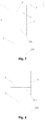
Fig. 1 is a schematic diagram of a structure of a prior leveling foot of a household appliance; -
Fig. 2 is a schematic diagram of a structure of a leveling device of an embodiment of the present disclosure; -
Fig. 3 is a schematic diagram of a structure of the leveling device of another embodiment of the present disclosure; -
Fig. 4 is a schematic diagram of a structure of the leveling device of another embodiment of the present disclosure; -
Fig. 5 is a schematic diagram of a structure of the leveling device of another embodiment of the present disclosure; -
Fig. 6 is a schematic diagram of an installation of the leveling device of an embodiment of the present disclosure; -
Fig. 7 is a schematic diagram of an installation of the leveling device of another embodiment of the present disclosure; -
Fig. 8 is a schematic diagram of an installation of the leveling device of another embodiment of the present disclosure; -
Fig. 9 is a schematic diagram of an installation of the leveling device of another embodiment of the present disclosure; -
Fig. 10 is a schematic diagram of a structure of the leveling foot of a washing machine of another embodiment of the present disclosure; -
Fig. 11 is a schematic diagram of a structure of the leveling foot of a washing machine of another embodiment of the present disclosure; -
Fig. 12 is a schematic diagram of a structure of the leveling foot of a washing machine of another embodiment of the present disclosure; -
Fig. 13 is a schematic diagram of a structure of the leveling foot of a washing machine of another embodiment of the present disclosure; -
Fig. 14 is a schematic diagram of a structure of a leveling device of another embodiment of the present disclosure; -
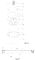
Fig. 15 is a diagram of sectional view of the leveling foot of the washing machine shown inFig. 14 of the present disclosure; -
Fig. 16 is an exploded diagram of the leveling foot of the washing machine shown inFig. 14 of the present disclosure; -
Fig. 17 is a schematic diagram of a working state of the leveling foot of a washing machine of the present disclosure. - Description of labels in the drawings: 1-foot base 2-plunger mechanism 201-plug body 202-supporting body 3-oil chamber 4-gas chamber 5-orifice 6-valve opening 7-high-pressure oil pipe 701-first high-pressure oil pipe group 702-second high-pressure oil pipe group 703- third high-pressure oil pipe group 704-fourth high-pressure oil pipe group 8-hollow chamber 9-housing 901-bottom board 10-leveling foot 1001-first foot group 1002-second foot group 1003-third foot group 1004-fourth foot group 11-door window 12-detergent box 13-control panel 14-washing drum 15-communicating device 16-cylinder block 17-valve board 18-sheath 1801-inner ring boss 1802-annular recess 19-adjustable foot 1901-outer ring boss 20-screw column 21-flexible accommodating body 2101-sealing strip mechanism 22-seal ring 23-locking mechanism 24-screw hole 25-valve block 26-ground 2601-ground pit 27-fixed foot
- The following is further and specific description of a leveling device of a household appliance and a household appliance having the same of the present disclosure with accompanying drawings.
- A leveling device of a household appliance of this embodiment is provided. The bottom of the household appliance is provided with leveling foot The leveling foot comprises a fixed part and a movable part, and a hollow chamber is formed between the fixed part and the movable part. The hollow chamber is provided with a hydraulic medium. Under the action of pressure, the hydraulic medium can be circulated in the hollow chamber inside the leveling foot and/or the hollow chamber between leveling feet to realize the expansion and contraction of the movable part, to perform automatic leveling.
- The leveling foot of the washing machine of the embodiment is under a certain pressure, and the hydraulic medium compresses gas, so that the adaptive expansion and contraction of the movable part is followed. When the pressure further increases, the gas is no longer compressed, the internal pressure of the gas reacts to the hydraulic medium and the movable part is with sufficient support force therewith. Therefore, the leveling foot of the washing machine of the embodiment has an adaptive automatic leveling function. The hydraulic medium of the embodiment is specifically selectable for hydraulic oil.
- The leveling device of a household appliance of the embodiment, according to the hydraulic principle, is provided with a hydraulic medium in the leveling foot. Under different pressures, the leveling foot is able to automatically perform adaptive adjustment due to the fluidity of the hydraulic medium.
- Therefore, the structure of the leveling device of a household appliance of the present embodiment is simple, and the cost is low. It is easy to use and has high reliability and it can remarkably reduce the vibration, reduce noise and improve the comfort of the experience of the washing machine for users.
- The household appliance of the embodiment is selected from any one of a washing machine, a refrigerator, a freezer, or an indoor unit of an air conditioner.
- As shown in from
Fig. 6 to Fig. 13 , a drum washing machine is taken as an example in the present disclosure. The drum washing machine comprises: - a
washing drum 14 for holding and washing clothes; - a
detergent box 12 for storing powder detergent, liquid detergent or softener; - a
control panel 13 for operating the washing machine; - a
door window 11 for opening to take out or put in clothes, - a motor assembly for connecting at least one rotatable drive shaft to achieve at least one output;
- a
housing 9 for keeping an entire frame and an exterior appearance of the washing machine; - a
bottom board 901 for installing the leveling device of the present disclosure. - As shown in
Fig. 6 , the household appliance of the embodiment comprises ahousing 9 and thebottom board 901 of thehousing 9 is provided with at least two levelingfeet 10. Each levelingfoot 10 is filled with hydraulic medium and gas within. Under different pressures, the hydraulic medium and the gas within the levelingfoot 10 interact with each other to realize the expansion and the contraction of the movable part, to level automatically. - The leveling
feet 10 of the embodiment are provided independently. Under different pressures, the hydraulic medium and part of the gas in each levelingfoot 10 flow mutually inside the hollow chamber 8 of each levelingfoot 10, which to achieve different amounts of compression. So the amount of compression of the levelingfoot 10 which is under bigger pressure is big, and the amount of compression of the levelingfoot 10 which is under smaller pressure is small, and automatically leveling of the washing machine is realized in such manner. - At the same time, the leveling device of a household appliance of the present embodiment is also able to self-level on the partial load during a washing process and a dewatering process of the washing machine. Therefore, lower vibration and less noise is achieved.
- As shown in
Fig. 7 , four corners of thebottom board 901 of thehousing 9 of the embodiment are provided with four feet, and two of them are levelingfeet 10 which are filled with hydraulic medium and gas. Under different pressures, the hydraulic medium and the gas within each levelingfoot 10 interact with each other to realize the expansion and the contraction of the movable part, to level automatically. The other two feet are fixedfeet 27, that is, they are common feet just for supporting and the height cannot be adjusted. In this manner, the adjustment can be achieved in a certain degree and cost can be reduced by the implementation. - As shown in
Fig. 8 , four corners of thebottom board 901 of thehousing 9 of the embodiment are provided with four feet, and three of them are levelingfeet 10 which are filled with hydraulic medium and gas. Under different pressures, the hydraulic medium and the gas within each levelingfoot 10 interact with each other to realize the expansion and the contraction of the movable part, to level automatically. The other one foot is a fixedfoot 27, that is, it is a common foot just for supporting and the height cannot be adjusted. In this manner, the adjustment can be achieved in a certain degree and cost can be reduced the method of implementation. - A structure of the leveling foot of the present embodiment is shown in
Fig. 2 , which comprises afoot base 1 and aplunger mechanism 2, and agas chamber 4 and anoil chamber 3 are isolated in thefoot base 1. Theoil chamber 3 is provided with the hydraulic medium. Thegas chamber 4 and theoil chamber 3 are communicated through anorifice 5 and avalve opening 6. One end of theplunger mechanism 2 is provided with a plug body which is set relatively slidably in theoil chamber 3 and keeps theoil chamber 3 sealed, and the other end of theplunger mechanism 2 is provided with a supportingbody 202. - When the
plunger mechanism 2 is under pressure, the hydraulic medium can flow from theoil chamber 3 to thegas chamber 4 through theorifice 5 and thevalve opening 6. The greater the pressure is, the longer the length ofplunger mechanism 2 being compressed into thefoot base 1 is, thereby achieving automatic adjustment of height. - A structure of another leveling foot of the present embodiment is shown in
Fig. 4 . The leveling foot comprises afoot base 1 and aplunger mechanism 2. Thefoot base 1 is provided with a hollow chamber 8 therein. One end of theplunger mechanism 2 is provided with aplug body 201 which is set relatively slidably in the hollow chamber 8 and keeps the hollow chamber 8 sealed to form an enclosed chamber, and the enclosed chamber is provided with the hydraulic medium. The volume of the hydraulic medium is less than the maximum volume of the enclosed chamber. - The leveling foot of the present embodiment is provided with only one hollow chamber 8. Therefore, some gas is required to be filled in the hollow chamber 8 if the hydraulic medium is to be allowed to flow with the
plunger mechanism 2 when theplunger mechanism 2 is under pressure. Therefore, the volume of the hydraulic medium is less than the maximum volume of the enclosed chamber. - When the
plunger mechanism 2 of the present embodiment is under pressure, the hydraulic medium compresses the gas in the enclosed chamber. And the greater the pressure is, the longer the length of theplunger mechanism 2 being compressed into thefoot base 1 is, thereby achieving the adjustment of height. - As shown in from
Fig. 7 to Fig. 13 , in the present disclosure, at least four leveling feet are evenly provided at four corners of thebottom board 901 of thehousing 9 or along the circumferential direction of thebottom board 901 of thehousing 9, and at least two of the levelingfeet 10 are communicated with each other. Each levelingfoot 10 is filled with hydraulic medium and gas. Within the first range of pressure, the hydraulic medium and the gas within eachfoot 10 interact with each other to realize the expansion and the contraction of the movable part, to level automatically. Within the second range of pressure, the hydraulic medium and the gas within the communicated levelingfeet 10 interact with each other to realize the expansion and the contraction of the movable part, to level automatically. - In the present embodiment, the leveling
feet 10 are communicated with each other so that the hydraulic medium inside the levelingfoot 10 not only flow inside itself but also be able to keep flow between the levelingfeet 10. When one of the levelingfeet 10 is subjected to compression, the hydraulic medium flows to the other leveling foot communicated with it. The amount of the hydraulic medium in the other leveling foot increases, and the pressure increases to make the foot stretch out so as to ensure sufficient supporting force. - A structure of a leveling foot of the present embodiment is shown in
Fig. 3 , which comprises afoot base 1, aplunger mechanism 2, and at least one high-pressure oil pipe. Agas chamber 4 and anoil chamber 3 are isolated in thefoot base 1. Theoil chamber 3 is filled with the hydraulic medium. Thegas chamber 4 and theoil chamber 3 are communicated through anorifice 5 and avalve opening 6. One end of theplunger mechanism 2 is provided with aplug body 201 which is set relatively slidably in theoil chamber 3 and keeps theoil chamber 3 sealed, and the other end of theplunger mechanism 2 is provided with a supportingbody 202. The high-pressure oil pipe 7 is respectively communicated with thegas chambers 4 of two leveling feet. - A structure of a leveling foot of the present embodiment is shown in
Fig. 3 , which comprises afoot base 1, aplunger mechanism 2, and at least one high-pressure oil pipe 7. Thefoot base 1 is provided with a hollow chamber 8 therein. One end of theplunger mechanism 2 is provided with aplug body 201 which is set relatively slidably in the hollow chamber 8 and keeps the hollow chamber 8 sealed to form an enclosed chamber, and the enclosed chamber is provided with the hydraulic medium. The volume of the hydraulic medium is less than the maximum volume of the enclosed chamber. Anorifice 5 and avalve opening 6 are provided respectively on the top of the enclosed chamber, and the high-pressure oil pipe 7 is respectively communicated with theorifices 5 and thevalve openings 6 of the two leveling feet. - Four leveling feet are provided in the present embodiment, and are divided into two sets of leveling feet being communicated with each other. Two adjacent leveling feet or two diagonally set leveling feet are respectively communicated with each other.
- Specifically, as shown in
Fig. 9 , four leveling feet are fixedly arranged on the four corners of thebottom board 901 of the washing machine. A plurality of high-pressure oil pipes 7 form a first high-pressureoil pipe group 701 which is communicated with two leveling feet on the left side of thebottom board 901 of the washing machine, and the two levelig feet form a firstleveling foot group 1001. A plurality of high-pressure oil pipes 7 form a second high-pressure oil pipe group 702which is communicated with two leveling feet on the right side of thebottom board 901 of the washing machine, and the two levelign feet form a secondleveling foot group 1002. - In this way, it enables the hydraulic medium and part of the gas of the first
leveling foot group 1001 under different pressures to flow mutually between the two leveling feet. And it enables hydraulic medium and part of the gas of thesecond foot group 1002 under different pressures to flow mutually between the two leveling feet. - As shown in
Fig.10 , it is another implementation method of the present embodiment. Four corners of thebottom board 901 of thehousing 9 are fixedly provided with four feet. A plurality of high-pressure oil pipes 7 form a first high-pressure oil pipe group 701which is communicated with two leveling feet on the left side of thebottom board 901 of the washing machine, and the two leveling feet form a firstleveling foot group 1001. Two feet on the right side of thebottom board 901 are fixedfeet 27, that is, they are common feet which cannot automatically adjust the height and are mainly used for support. Or, a plurality of high-pressure oil pipes 7 form a second high-pressure oil pipe group 702which is communicated with two leveling feet on the right side of thebottom board 901 of the washing machine, and the two leveling feet form a secondleveling foot group 1002, and two feet on the left side of thebottom board 901 are fixedfeet 27, that is, they are common feet which cannot automatically adjust the height and are mainly used for support. Adjustment can be achieved in a certain degree and cost can be reduced by the method of implementation. - As shown in
Fig. 11 , four corners of thebottom board 901 of the washing machine are fixedly provided with four leveling feet. A plurality of high-pressure oil pipes 7 form a third high-pressureoil pipe group 703 which is communicated with two leveling feet at the rear of thebottom board 901 of the washing machine, and the two feet form a third leveling foot group 1003.A plurality of high-pressure oil pipes 7 form a fourth high-pressure oil pipe group 704which is communicated with two leveling feet at the front of thebottom board 901 of the washing machine, and the two feet form a fourthleveling foot group 1004. - In this way, it enables the hydraulic medium and part of the gas of the third
leveling foot group 1003 under different pressures to flow mutually between the two leveling feet. And it enables the hydraulic medium and part of the gas of the fourthleveling foot group 1004 under different pressures to flow mutually between the two leveling feet. - As shown in
Fig. 12 , it is another implementation method of the present embodiment. Four corners of thebottom board 901 of thehousing 9 are fixedly provided with four feet. A plurality of high-pressure oil pipes 7 form a third high-pressure oil pipe group 703which is communicated with two leveling feet at the rear of thebottom board 901 of the washing machine, and the two leveling feet form a thirdleveling foot group 1003. Two leveling feet at the front of thebottom board 901 are fixedfeet 27, that is, they are common feet which cannot automatically adjust the height and are mainly used for support. Or, a plurality of high-pressure oil pipes 7 form a fourth high-pressure oil pipe group 704which is communicated with two leveling feet at the front of thebottom board 901 of the washing machine, and the two feet form a fourthleveling foot group 1004. And two leveling feet at the rear of thebottom board 901 are fixedfeet 27, that is, they are common feet which cannot automatically adjust the height and are mainly used for support. Adjustment can be achieved in a certain degree and cost can be reduced by the method of implementation. - As shown in
Fig. 13 , at least four levelingfeet 10 are provided evenly in four corners of thebottom board 901 of thehousing 9 or along the circumferential direction of thebottom board 901 of thehousing 9. Each levelingfoot 10 is filled with hydraulic medium and gas. Within the first range of pressure, the hydraulic medium and the gas inside the each levelingfoot 10 interact with each other to realize the expansion and the contraction of the movable part, to level automatically. Within the second range of pressure, the hydraulic medium and the gas inside the communicated levelingfeet 10 interact with each other to realize the expansion and the contraction of the movable part, to level automatically. This way realizes the communication between all the leveling feet, and the liquid medium can flow between all the leveling feet. The range of adjustment is larger, and the effect of adjustment is better. - Specifically, an enclosed chamber which is filled with hydraulic medium and gas is provided inside the leveling
foot 10. The enclosed chamber is communicated with at least one high-pressure oil pipe 7, and the high-pressure oil pipe 7 of each levelingfoot 7 is respectively communicated to a communicatingdevice 15 to achieve the mutual communication between all the levelingfeet 10. - Therefore, the leveling device of the present embodiment enables that the amount of compression of the leveling foot under large pressure is large and the leveling foot under small pressure extends by the action of oil pressure, and then automatically levels the washing machine. At the same time, the leveling device of a household appliance of the present embodiment is also able to self-level on the partial load during a washing process and a dewatering process of the washing machine. Therefore, lower vibration and less noise is achieved.
- As shown in
Fig.14, Fig.15 andFig.16 , a leveling foot of a washing machine with a function of automatic leveling of this embodiment comprises a foot base, a flexibleaccommodating body 21 and anadjustable foot 19. The foot base is provided with a hollow chamber and the hollow chamber at least comprises agas chamber 4 for being filled with gas. The flexibleaccommodating body 21 is provided in the hollow chamber and is communicated with thegas chamber 4. - The flexible
accommodating body 21 has an accommodating chamber therein and hydraulic medium is provided inside the accommodating chamber. The hydraulic medium can flow to thegas chamber 4 under pressure. - One end of the
adjustable foot 19 is relatively slidably set in the hollow chamber and the flexibleaccommodating body 21 is in contact with or connected to theadjustable foot 19. - The leveling foot of the washing machine with a function of automatic leveling of the embodiment, according to the hydraulic principle, is provided with the hydraulic medium therein. Under different pressures, the leveling foot is able to automatically perform adaptive adjustment due to the fluidity of the hydraulic medium.
- In addition, the leveling foot of the washing machine with the function of automatic leveling of the embodiment holds the hydraulic medium in the enclosed flexible
accommodating body 21, and the flexibleaccommodating body 21 is set inside the theadjustable foot 19. It effectively solves the problem of the leakage of the hydraulic medium and ensures the working stability of the leveling foot. - Therefore, the structure of the leveling foot of the washing machine of the present embodiment is simple, and the cost is low. It is easy to use and has high reliability, and it can remarkably reduce the vibration, reduce noise, and improve the comfort of the experience of the washing machine for users.
- Specifically, a
valve board 17 is provided inside the hollow chamber of the foot base. The hollow chamber is divided to an upper chamber and a lower chamber by thevalve board 17, and the upper chamber is agas chamber 4 which is applied to be filled with gas. One end of the flexibleaccommodating body 21 is open and an accommodating chamber is provided therein. The hydraulic medium is provided inside the accommodating chamber. The flexibleaccommodating body 21 is provided in the lower chamber and the opening of the flexibleaccommodating body 21 is hermetically connected to thevalve board 17. Thevalve board 17 is provided with a conducting hole through which the hydraulic medium flows to the gas chamber under pressure. One end of theadjustable foot 19 is relatively slidably set in the lower chamber of the hollow chamber. - The hollow chamber of the foot base of the embodiment is divided to chambers which are communicated with each other. One chamber is applied as the
gas chamber 4 and the other chamber is provided with the flexibleaccommodating body 21 therein. And theadjustable foot 19 is relatively slidably set in the lower chamber of the hollow chamber. It enables the flexibleaccommodating body 21 to set in the enclosed chamber between theadjustable foot 19 and the lower chamber of the hollow chamber. The flexibleaccommodating body 21 is squeezed when the theadjustable foot 19 is compressed, and the hydraulic medium inside the flexibleaccommodating body 21 flows under compression to achieve automatic leveling. - Further, the foot base comprises a
cylinder block 16 and asheath 18 which are connected with each other. Thevalve board 17 is provided between thecylinder block 16 and thesheath 18. Above thevalve board 17 is thecylinder block 16 and thegas chamber 4 is inside thecylinder blcok 16. Below thevalve board 17 is thesheath 18, and the flexibleaccommodating body 21 is provided inside thesheath 18. One end of theadjustable foot 19 is relatively slidably set inside thesheath 18. - In the present embodiment, when the
valve board 17, thecylinder block 16 and thesheath 18 are assembled, it is necessary to maintain the sealing property of the assembly to satisfy flow ability of the hydraulic medium in the flexibleaccommodating body 21. Thus, thecylinder block 16, thevalve board 17 and thesheath 18 are fastened together by bolts, and thecylinder block 16, thevalve board 17 and thesheath 18 are respectively provided with screw holes 24. Anannular recess 1802 is provided on the inner side of the upper opening of thesheath 18, and the opening of the flexibleaccommodating body 21 is flanged outward to form asealing strip mechanism 2101. The sealingstrip mechanism 2101 is installed inside theannular recess 1802. After thevalve board 17 and thesheath 18 are fastened together, the sealingstrip mechanism 2101 is press-fitted in theannular recess 1802 to achieve a sealing connection. - Further, a
seal ring 22 is provided between thevalve board 17 and thecylinder block 16 in the embodiment, enabling a sealed connection between thevalve board 17 and thecylinder block 16, to avoid leakage of gas and oil. - An end of the
sheath 18 is provided with aninner ring boss 1801 and an end of theadjustable foot 19 is provided with anouter ring boss 1901. Theinner ring boss 1801 and theouter ring boss 1901 are engaged with each other. Theinner ring boss 1801 cooperates with theouter ring boss 1901 to form alocking mechanism 23, to prevent theadjustable foot 19 from departing from thesheath 18. - Further, the diameter of
inner ring boss 1801 is smaller than the diameter ofouter ring boss 1901, to perform a locking function to theadjustable foot 19. It prevents theadjustable foot 19 from departing from thesheath 18 accidentally, which results in infinite expansion of the flexibleaccommodating body 21 to cause thesheath 18 to burst at high pressure or results in that the flexibleaccommodating body 21 is in direct contact with the ground to cause the burst due to sharp objects. - The flexible
accommodating body 21 of the present embodiment is a bellows mechanism made of a flexible material. The upper end of the bellows mechanism is open, the lower end is closed, and the closed end is in contact with or connected to the adjustable foot. The flexibleaccommodating body 21 is made of a flexible material, which is with better deformation, to accommodate with the telescopic and extrusion of theadjustable foot 19. The bellows mechanism allows compression under large pressure and recovery under small pressure. - The
valve board 17 of the embodiment is provided with anorifice 5 and/or avalve opening 6, and it enables that the hydraulic medium and the gas can slowly pass through theorifice 5. Avalve block 25 is provided above thevalve opening 6, enabling thevalve opening 6 to be sealed to throttle when the leveling foot is subjected to great force suddenly or is under great pressure, to prevent the failure of the foot caused by excessive pressure of the hydraulic medium. - The
cylinder block 16 of the embodiment is provided with ascrew column 20 for connecting the bottom of the washing machine. Thescrew column 20 is able to be screwed directly into screw holes of the bottom board of the washing machine. Of course, it is possible to conceive that thescrew column 20 can be removed and some through-holes are provided, and then the leveling feet are fixedly connected to thebottom board 901 by bolts or screws. - The
adjustable foot 19 of the embodiment is provided with a hollow chamber. Theadjustable foot 19 is installed on thesheath 18 and is wrapped with a flexibleaccommodating body 21. Under the pressure which acts on the flexibleaccommodating body 21, the hydraulic medium flows to thegas chamber 4, and the flexibleaccommodating body 21 drives theadjustable foot 19 to expand and contract, to achieve the automatic leveling. - The leveling foot of the washing machine of the embodiment uses the gas as the elastic medium and the liquid medium as the force transmission medium. It not only has a good ability of cushioning, but also has a damping effect. At the same time, it can also adjust the height of the foot itself according to the size of the pressure it withstands.
- When the load of the leveling foot is large, the
adjustable foot 19 moves upward to make the volume of the hollow chamber of the flexibleaccommodating body 21 which is full of the hydraulic medium reduce. The hydraulic medium is forced to flow into thegas chamber 4 through theorifice 5 or thevalve opening 6. The volume of thegas chamber 4 is reduced, the pressure of the gas is increased, and the height of the entire foot is reduced. When the external load is equal to the pressure of the gas and the hydraulic medium, theadjustable foot 19 stops moving up. Thus, the distance that theadjustable foot 19 moves upward into thesheath 18 is related to the size of the load subjected. At this time, the relative position of theadjustable foot 19 and thebottom board 901 of the washing machine is not changed any longer and the automatic adjustment of the leveling foot of the washing machine is completed. - As shown in
Figure 17 , it specifically explains the principle of leveling. After the washing machine is installed, it results in different levels of different feet height because theground 26 is uneven, and the position of the foot located in aground pit 2601 is low. It is possible to know that the foot in the high position bears the weight of the washing machine at first and bears greater gravity. The foot in the low position on the state of virtual legs may bear smaller gravity. The adjustable foot of the foot in the high position moves upward under greater pressure. The height of the entire foot gets small to make the volume of the hollow chamber of the flexibleaccommodating body 21 to be compressed and reduced, and forces the hydraulic medium to flow into the orifice or the valve opening and flow into the foot which is in the lower position through the high-pressure oil pipe group. So the hydraulic medium of the flexible accommodating body of the foot in the lower positin gets more and more and the flexible accommodating body expands to drive the adjustable foot to extend. - When hydraulic pressures of the leveling foot in the higher position and the leveling foot in the lower position are equal, the hydraulic medium no longer flows through the high-pressure oil pipe group and the relative positions of the adjustable foot and the bottom board of the washing machine no longer change, and the automatic adjustment of the leveling feet of the washing machine is completed.
- In the washing process and the dewatering process of the washing machine, because the hydraulic medium still flows slowly to self-level, the vibration noise of the washing machine is greatly reduced.
- A washing machine which has the above-mentioned leveling feet of a washing machine with a function of automatic leveling is provided at the same time in the embodiment. The washing machine comprises a
housing 9, and the bottom of thehousing 9 is provided with a plurality of the leveling feet mentioned. The hydraulic medium provided inside the leveling feet of the washing machine can flow inside the leveling feet and/or between the leveling feet to achieve the leveling. - The factory setting of the washing machine of the embodiment is preferably that heights of four leveling feet of the washing machine are the same. The washing machine is randomly placed on an uneven ground and the four leveling feet bear different pressures according to the uneven states and the lengths of which adjustable feet are pressed into sheaths are different, and then the automatic leveling of the washing machine is realized.
- Further illustrations which are necessary for the above embodiments are:
- 1. Every two of the feet of the embodiments of the present disclosure are communicated. It can be three or more and the number N≥2, preferably two. It costs the lowest and can achieve better results.
- Four end openings of the communicating
device 15 are applied to be respectively connected with four leveling feet. It is reasonable that three, five, six or N end openings of the communicatingdevice 15 are applied, and the end openings are respectively connected with three, five, six or N feet. The above-described embodiments apply four leveling feet which is the most suitable merely in the situation of being capable of achieving the described functions, to control the cost to the minimum. - 2. The embodiments of the present disclosure take a drum washing machine as an example to describe the principle and the method of the automatic leveling of the drum washing machine. What is easy to associate with is that the present disclosure can be applied to a pulsator washing machine.
- 3. The embodiments of the present disclosure take a washing machine as an example to describe the principle and the method of the automatic leveling of the washing machine. What is easy to associate with is that the present disclosure can be applied to refrigerators, freezers, dishwashers, air conditioning indoor units, water dispenser, microwave ovens, roasters, floor air conditioning fans and air purifiers and other household appliances.
- The foregoing is merely illustrative of the preferred embodiments of the present invention and is not intended to be limiting of the present invention. While the invention has been disclosed by way of example with reference to the preferred embodiments, it is not intended to be limiting of the invention. Any person skilled in the art will, without departing from the scope of the technical solution of the present invention, may make use of the technical contents of the above-mentioned tips to make some alterations or modifications to equivalent embodiments, but without departing from the scope of the technical solution of the present invention. Any and all modifications, equivalents, and modifications of the foregoing embodiments are within the scope of the present invention without departing from the spirit of the technical solution of the present invention in accordance with the technical details of the present invention.
Claims (10)
- A leveling device of a household appliance, wherein: a bottom of the household appliance is provided with a leveling foot which comprises a fixed part and a movable part, a hollow chamber is formed between the fixed part and the movable part and the hollow chamber is provided with a hydraulic medium;
the hydraulic medium is circulated in the hollow chamber inside the leveling foot and/or the hollow chambers between the leveling feet under an action of pressure for expanding and contracting the movable part, to execute automatic leveling. - The leveling device of the household appliance according to claim 1, wherein:the household appliance comprises a housing and a bottom board of the housing is provided with at least two leveling feet,each leveling foot is filled with the hydraulic medium and gas, the hydraulic medium and gas inside each leveling foot interact with each other for expanding and the contracting the movable part under different pressures, to level automatically.
- The leveling device of the household appliance according to claim 2, wherein:the leveling foot comprises a foot base and a plunger mechanism, and a gas chamber and an oil chamber are isolated inside the foot base,the oil chamber is provided with the hydraulic medium, the gas chamber and the oil chamber are communicated through an orifice and a valve opening;one end of the plunger mechanism is provided with a plug body which is set relatively slidably in the oil chamber and keeps the oil chamber sealed, the other end of the plunger mechanism is provided with a supporting body.
- The leveling device of the household appliance according to claim 2, wherein:the leveling foot comprises a foot base and a plunger mechanism, the foot base is provided with a hollow chamber therein,one end of the plunger mechanism is provided with a plug body and the plug body is set relatively slidably in the hollow chamber and keeps the hollow chamber sealed to form an enclosed chamber which is provided with the hydraulic medium,a volume of the hydraulic medium is less than a maximum volume of the enclosed chamber.
- The leveling device of the household appliance according to claim 1, wherein:the household appliance comprises a housing and at least four leveling feet are evenly provided at four corners of a bottom board of the housing or along a circumferential direction of the bottom board of the housing, at least two leveling feet are communicated with each other;each leveling foot is filled with the hydraulic medium and gas within, and within a first range of pressure, the hydraulic medium and the gas within each foot interact with each other for expanding and a contracting of the movable part, to level automatically,and within a second range of pressure, the hydraulic medium and the gas within the leveling feet communicated interact with each other for expanding and the contracting the movable part, to level automatically.
- The leveling device of the household appliance according to claim 5, wherein:the leveling foot comprises a foot base, a plunger mechanism and at least one high-pressure oil pipe, a gas chamber and an oil chamber are isolated in the foot base, the oil chamber is filled with the hydraulic medium and the gas chamber and the oil chamber are communicated through an orifice and a valve opening,one end of the plunger mechanism is provided with a plug body which is set relatively slidably in the oil chamber and keeps the oil chamber sealed, and the other end of the plunger mechanism is provided with a supporting body, and the high-pressure oil pipe are respectively communicated with the gas chambers of two leveling feet.
- The leveling device of the household appliance according to claim 5, wherein:the leveling foot comprises a foot base, a plunger mechanism and at least one high-pressure oil pipe,a hollow chamber is provided inside the foot base, one end of the plunger mechanism is provided with a plug body which is set relatively slidably in the hollow chamber and keeps the hollow chamber sealed to form an enclosed chamber,the enclosed chamber is provided with the hydraulic medium, and a volume of the hydraulic medium is less than a maximum volume of the enclosed chamber, and an orifice and a valve opening are provided respectively on a top of the enclosed chamber, and the high-pressure oil pipe is respectively communicated with the orifices and the valve openings of the two leveling feet.
- The leveling device of the household appliance according to claim 5, wherein:four leveling feet are provided and divided into two sets of leveling feet which are communicated with each other,two adjacent leveling feet or two diagonally set leveling feet are respectively communicated with each other.
- The leveling device of the household appliance according to claim 1, wherein:the household appliance comprises a housing and at least four leveling feet are provided evenly at four corners of a bottom board of the housing or along a circumferential direction of the bottom board of the housing, each leveling foot is filled with the hydraulic medium and gas,within a first range of pressure, the hydraulic medium and the gas inside each leveling foot interact with each other for expanding and contracting the movable part, to level automatically,and within a second range of pressure, the hydraulic medium and the gas inside the leveling feet communicated interact with each other for expanding and contracting the movable part, to level automatically,preferably, an enclosed chamber for being filled with the hydraulic medium and gas is provided inside the leveling foot, the enclosed chamber is communicated with at least one high-pressure oil pipe, the high-pressure oil pipe of each leveling foot is respectively communicated with a communicating device to make all the leveling feet communicated with each other.
- A household appliance, wherein: the household appliance is provided with the leveling device according to any one of claims from 1 to 9.
Applications Claiming Priority (2)
| Application Number | Priority Date | Filing Date | Title |
|---|---|---|---|
| CN201610229118.0A CN105757408B (en) | 2016-04-13 | 2016-04-13 | A kind of household appliance and its leveling device |
| PCT/CN2016/085072 WO2017177528A1 (en) | 2016-04-13 | 2016-06-07 | Levelling device for household electrical appliance and household electrical appliance having same |
Publications (3)
| Publication Number | Publication Date |
|---|---|
| EP3444517A1 true EP3444517A1 (en) | 2019-02-20 |
| EP3444517A4 EP3444517A4 (en) | 2019-02-20 |
| EP3444517B1 EP3444517B1 (en) | 2020-11-18 |
Family
ID=56335027
Family Applications (1)
| Application Number | Title | Priority Date | Filing Date |
|---|---|---|---|
| EP16898343.5A Active EP3444517B1 (en) | 2016-04-13 | 2016-06-07 | Levelling device for household electrical appliance and household electrical appliance having same |
Country Status (5)
| Country | Link |
|---|---|
| US (1) | US10745850B2 (en) |
| EP (1) | EP3444517B1 (en) |
| JP (1) | JP6731493B2 (en) |
| CN (1) | CN105757408B (en) |
| WO (1) | WO2017177528A1 (en) |
Families Citing this family (36)
| Publication number | Priority date | Publication date | Assignee | Title |
|---|---|---|---|---|
| CN105755750B (en) * | 2016-04-13 | 2024-04-02 | 青岛海尔洗衣机有限公司 | Washing machine footing and washing machine with automatic leveling function |
| CN105755757B (en) * | 2016-04-13 | 2024-01-12 | 青岛海尔洗衣机有限公司 | Washing machine feet and washing machine with automatic leveling function |
| CN107558113B (en) * | 2016-06-30 | 2021-04-27 | 青岛海尔洗衣机有限公司 | Self-leveling washing machine |
| CN107761312B (en) * | 2016-08-16 | 2020-10-16 | 青岛海尔洗衣机有限公司 | Washing machine bottom foot with automatic leveling function and washing machine |
| CN107761321B (en) * | 2016-08-16 | 2020-07-14 | 青岛胶南海尔洗衣机有限公司 | Washing machine feet and washing machine with automatic leveling function |
| CN107761311B (en) * | 2016-08-16 | 2020-06-23 | 青岛胶南海尔洗衣机有限公司 | Washing machine bottom foot with automatic leveling function and washing machine |
| CN107841856B (en) * | 2016-09-18 | 2020-10-02 | 青岛海尔洗衣机有限公司 | A washing machine with automatic leveling function |
| CN107841855B (en) * | 2016-09-18 | 2020-10-27 | 青岛海尔洗衣机有限公司 | A washing machine hydraulic leveling device and filling method thereof |
| DE102016118184B3 (en) * | 2016-09-27 | 2017-10-26 | Sartorius Lab Instruments Gmbh & Co. Kg | Use of a hydraulic shock absorber and laboratory device |
| CN106439402B (en) * | 2016-11-02 | 2019-04-30 | 空气动力学国家重点实验室 | a leveling device |
| CN106843284A (en) * | 2016-12-29 | 2017-06-13 | 无锡小天鹅股份有限公司 | The automatic adjusting balance method of household electrical appliance and household electrical appliance |
| CN108278452B (en) | 2017-01-06 | 2020-12-22 | 青岛海尔洗衣机有限公司 | Foot for household appliance and household appliance |
| CN108277617B (en) | 2017-01-06 | 2021-04-23 | 青岛胶南海尔洗衣机有限公司 | Foot for household appliance and household appliance |
| CN108278450B (en) | 2017-01-06 | 2021-08-03 | 青岛海尔洗衣机有限公司 | Foot for household appliance and household appliance |
| CN108317209B (en) * | 2017-01-16 | 2020-11-03 | 青岛海尔洗衣机有限公司 | Footing for household appliance and household appliance |
| CN108626526B (en) * | 2017-03-22 | 2021-04-27 | 青岛胶南海尔洗衣机有限公司 | Foot for household appliance and household appliance |
| CN108626527B (en) * | 2017-03-22 | 2021-04-20 | 青岛胶南海尔洗衣机有限公司 | Foot for household appliance and household appliance |
| CN108626530B (en) * | 2017-03-23 | 2021-04-30 | 青岛胶南海尔洗衣机有限公司 | Footing for household appliance and household appliance |
| CN108626532B (en) * | 2017-03-23 | 2021-03-30 | 青岛胶南海尔洗衣机有限公司 | Foot for household appliance and household appliance |
| CN108626531B (en) * | 2017-03-23 | 2021-09-07 | 青岛胶南海尔洗衣机有限公司 | Foot for household appliance and household appliance |
| CN108625122B (en) * | 2017-03-23 | 2021-03-26 | 青岛胶南海尔洗衣机有限公司 | Foot for household appliance and household appliance |
| CN108626305B (en) * | 2017-03-23 | 2021-10-29 | 青岛海尔洗衣机有限公司 | Foot for household appliance, washing machine and control method thereof |
| CN108660698B (en) * | 2017-03-30 | 2020-12-29 | 青岛海尔洗衣机有限公司 | A hydraulic lifting foot, a washing machine with the foot and a control method thereof |
| CN108660697B (en) * | 2017-03-30 | 2021-05-11 | 青岛胶南海尔洗衣机有限公司 | A leveling device for household appliances and a washing machine with the same |
| CN108660680B (en) | 2017-03-30 | 2020-10-16 | 青岛海尔洗衣机有限公司 | Leveling device, washing machine with leveling device and control method of washing machine |
| CN109140131B (en) * | 2017-06-19 | 2021-07-30 | 青岛胶南海尔洗衣机有限公司 | Foot for household appliance and household appliance |
| CN109140138B (en) * | 2017-06-19 | 2021-10-29 | 青岛海尔洗衣机有限公司 | Foot for household appliance and household appliance |
| CN109140137B (en) * | 2017-06-19 | 2021-09-07 | 青岛胶南海尔洗衣机有限公司 | Foot for household appliance and household appliance |
| CN109281980B (en) * | 2017-07-21 | 2021-03-16 | 青岛海尔洗衣机有限公司 | Foot for household appliance and household appliance |
| CN109323511B (en) * | 2017-07-31 | 2022-04-29 | 青岛海尔智能技术研发有限公司 | A refrigerator with automatic leveling function |
| CN109423860B (en) | 2017-09-01 | 2022-05-13 | 青岛海尔洗衣机有限公司 | Household electrical appliance is with supporting levelling device and household electrical appliance |
| CN109424824B (en) * | 2017-09-01 | 2022-04-05 | 青岛海尔洗衣机有限公司 | Household electrical appliance is with supporting levelling device and household electrical appliance |
| CN110701431A (en) * | 2018-07-09 | 2020-01-17 | 刘冠阳 | Household appliance leveling device |
| CN109404483A (en) * | 2018-10-15 | 2019-03-01 | 佛山美石机械有限公司 | A kind of bottle blowing machine is with being conveniently adjusted horizontal pedestal |
| CN115897170B (en) * | 2021-08-27 | 2025-10-17 | 无锡小天鹅电器有限公司 | Base device and clothes treatment equipment |
| TWM660278U (en) * | 2023-07-20 | 2024-09-11 | 吳易璋 | Buffer hydraulic pads |
Family Cites Families (29)
| Publication number | Priority date | Publication date | Assignee | Title |
|---|---|---|---|---|
| US2908472A (en) * | 1954-10-07 | 1959-10-13 | Frederick W Mcdonald | Automatic compensating device |
| US3954241A (en) * | 1975-03-31 | 1976-05-04 | Conchemco, Incorporated | Leveling assembly |
| JPS5334052A (en) * | 1976-09-08 | 1978-03-30 | Matsushita Electric Ind Co Ltd | Mounting support |
| US4342214A (en) * | 1980-06-16 | 1982-08-03 | Neuendorf J R | Pilot assembly for progressive die machines |
| US4585092A (en) * | 1982-09-29 | 1986-04-29 | Facom | Device for setting the attitude and the measuring height of the body of a vehicle to be checked on a surface plate, elevator, stays or other means without subjecting it to any warping stress |
| DE3420557A1 (en) * | 1984-06-01 | 1985-12-12 | Ficht GmbH, 8011 Kirchseeon | HYDROPNEUMATIC SUSPENSION DEVICE |
| DE3519479A1 (en) * | 1985-05-31 | 1986-12-11 | Miele & Cie GmbH & Co, 4830 Gütersloh | Domestic appliance with adjustable appliance feet |
| JPH0610982A (en) * | 1992-06-22 | 1994-01-21 | Tokico Ltd | Gas spring with lock mechanism |
| US6009815A (en) * | 1995-01-27 | 2000-01-04 | Proco, Inc. | Stabilized table, stabilizer for tables, and method of stabilizing tables |
| KR0174363B1 (en) * | 1996-09-12 | 1999-02-18 | 변가옥 | Leveling device of furniture |
| CH695348A5 (en) * | 2001-06-28 | 2006-04-13 | V Zug Ag | Washing machine has several height-adjustable feet for counter-balance level differences on base surface |
| DE10156397B4 (en) * | 2001-11-16 | 2007-06-21 | A-Z Ausrüstung Und Zubehör Gmbh & Co. Kg | Leveling system for household machines |
| KR20040003391A (en) * | 2002-07-02 | 2004-01-13 | 강희복 | A water level setting construction of laundry. |
| DE20302388U1 (en) * | 2003-02-14 | 2004-06-24 | A-Z Ausrüstung Und Zubehör Gmbh & Co. Kg | Leveling system for household machines |
| AU2005274676B2 (en) * | 2004-08-16 | 2011-12-15 | Flat Pty Ltd | A support for supporting a structure on a surface |
| CA2536822C (en) * | 2005-02-17 | 2012-04-10 | Steeve Cournoyer | Device for adjusting the attitude of an object |
| IE20080318A1 (en) * | 2007-04-23 | 2008-10-29 | Frank Sorohan | A stabilising device |
| CN201100362Y (en) * | 2007-10-10 | 2008-08-13 | 王冬雷 | Product bottom corner for automatic height adjustment |
| US20100237205A1 (en) * | 2009-03-20 | 2010-09-23 | Steve Hirsh | Stabilizing foot |
| EP2336416B1 (en) * | 2009-12-15 | 2013-02-20 | Electrolux Home Products Corporation N.V. | Household appliance with improved support stability |
| CN104329544A (en) * | 2014-10-29 | 2015-02-04 | 苏州华冲精密机械有限公司 | Novel multifunctional machine tool vibration-damping sizing block |
| CN104534788B (en) * | 2014-12-24 | 2017-05-24 | 合肥美的电冰箱有限公司 | Bottom foot assembly of refrigerator and refrigerator |
| CN205173878U (en) * | 2015-12-09 | 2016-04-20 | 徐州和胜重工有限公司 | 4 of area locking are supported hydraulic pressure levelling mechanism |
| CN205775399U (en) * | 2016-04-13 | 2016-12-07 | 青岛海尔洗衣机有限公司 | There is washing machine foot and the washing machine of automatic flat-adjustable function |
| CN105755757B (en) * | 2016-04-13 | 2024-01-12 | 青岛海尔洗衣机有限公司 | Washing machine feet and washing machine with automatic leveling function |
| CN205636216U (en) * | 2016-04-13 | 2016-10-12 | 青岛海尔洗衣机有限公司 | Washing machine footing and washing machine with auto leveling function |
| CN105755750B (en) * | 2016-04-13 | 2024-04-02 | 青岛海尔洗衣机有限公司 | Washing machine footing and washing machine with automatic leveling function |
| CN205640067U (en) * | 2016-04-13 | 2016-10-12 | 青岛海尔洗衣机有限公司 | Domestic appliance and levelling device thereof |
| CN107588290B (en) * | 2016-07-08 | 2020-05-22 | 青岛海尔洗衣机有限公司 | Household appliance |
-
2016
- 2016-04-13 CN CN201610229118.0A patent/CN105757408B/en active Active
- 2016-06-07 WO PCT/CN2016/085072 patent/WO2017177528A1/en not_active Ceased
- 2016-06-07 EP EP16898343.5A patent/EP3444517B1/en active Active
- 2016-06-07 JP JP2018553975A patent/JP6731493B2/en active Active
- 2016-06-07 US US15/562,637 patent/US10745850B2/en active Active
Also Published As
| Publication number | Publication date |
|---|---|
| CN105757408A (en) | 2016-07-13 |
| CN105757408B (en) | 2024-02-20 |
| EP3444517B1 (en) | 2020-11-18 |
| US10745850B2 (en) | 2020-08-18 |
| EP3444517A4 (en) | 2019-02-20 |
| WO2017177528A1 (en) | 2017-10-19 |
| US20180187362A1 (en) | 2018-07-05 |
| JP2019511324A (en) | 2019-04-25 |
| JP6731493B2 (en) | 2020-07-29 |
Similar Documents
| Publication | Publication Date | Title |
|---|---|---|
| US10745850B2 (en) | Leveling device of household appliance and household appliance having the same | |
| US10221517B2 (en) | Foot of a washing machine with automatic leveling function and a washing machine thereof | |
| US10227723B2 (en) | Foot of washing machine with automatic leveling function and washing machine | |
| CN205640067U (en) | Domestic appliance and levelling device thereof | |
| CN205636216U (en) | Washing machine footing and washing machine with auto leveling function | |
| CN205775399U (en) | There is washing machine foot and the washing machine of automatic flat-adjustable function | |
| US20180245266A1 (en) | Hydraulic leveling base and washing machine | |
| US10704188B2 (en) | Automatic leveling washing machine | |
| JP6889240B2 (en) | Home appliances | |
| CN107841855A (en) | A kind of washing machine hydro -leveling device and its method for filling | |
| CN107841856A (en) | A kind of washing machine with automatic flat-adjustable function | |
| WO2019042393A1 (en) | Supporting and leveling device for household appliance and household appliance | |
| CN108660697A (en) | A kind of levelling device of household electrical appliance and the washing machine with the levelling device | |
| CN108612963A (en) | A kind of household electrical appliance footing and household electrical appliance |
Legal Events
| Date | Code | Title | Description |
|---|---|---|---|
| STAA | Information on the status of an ep patent application or granted ep patent |
Free format text: STATUS: THE INTERNATIONAL PUBLICATION HAS BEEN MADE |
|
| PUAI | Public reference made under article 153(3) epc to a published international application that has entered the european phase |
Free format text: ORIGINAL CODE: 0009012 |
|
| STAA | Information on the status of an ep patent application or granted ep patent |
Free format text: STATUS: REQUEST FOR EXAMINATION WAS MADE |
|
| 17P | Request for examination filed |
Effective date: 20181002 |
|
| A4 | Supplementary search report drawn up and despatched |
Effective date: 20190107 |
|
| AK | Designated contracting states |
Kind code of ref document: A1 Designated state(s): AL AT BE BG CH CY CZ DE DK EE ES FI FR GB GR HR HU IE IS IT LI LT LU LV MC MK MT NL NO PL PT RO RS SE SI SK SM TR |
|
| AX | Request for extension of the european patent |
Extension state: BA ME |
|
| DAV | Request for validation of the european patent (deleted) | ||
| DAX | Request for extension of the european patent (deleted) | ||
| GRAP | Despatch of communication of intention to grant a patent |
Free format text: ORIGINAL CODE: EPIDOSNIGR1 |
|
| STAA | Information on the status of an ep patent application or granted ep patent |
Free format text: STATUS: GRANT OF PATENT IS INTENDED |
|
| INTG | Intention to grant announced |
Effective date: 20200526 |
|
| GRAS | Grant fee paid |
Free format text: ORIGINAL CODE: EPIDOSNIGR3 |
|
| GRAA | (expected) grant |
Free format text: ORIGINAL CODE: 0009210 |
|
| STAA | Information on the status of an ep patent application or granted ep patent |
Free format text: STATUS: THE PATENT HAS BEEN GRANTED |
|
| AK | Designated contracting states |
Kind code of ref document: B1 Designated state(s): AL AT BE BG CH CY CZ DE DK EE ES FI FR GB GR HR HU IE IS IT LI LT LU LV MC MK MT NL NO PL PT RO RS SE SI SK SM TR |
|
| REG | Reference to a national code |
Ref country code: GB Ref legal event code: FG4D |
|
| REG | Reference to a national code |
Ref country code: CH Ref legal event code: EP |
|
| REG | Reference to a national code |
Ref country code: DE Ref legal event code: R096 Ref document number: 602016048360 Country of ref document: DE |
|
| REG | Reference to a national code |
Ref country code: IE Ref legal event code: FG4D |
|
| REG | Reference to a national code |
Ref country code: AT Ref legal event code: REF Ref document number: 1336161 Country of ref document: AT Kind code of ref document: T Effective date: 20201215 |
|
| REG | Reference to a national code |
Ref country code: AT Ref legal event code: MK05 Ref document number: 1336161 Country of ref document: AT Kind code of ref document: T Effective date: 20201118 |
|
| REG | Reference to a national code |
Ref country code: NL Ref legal event code: MP Effective date: 20201118 |
|
| PG25 | Lapsed in a contracting state [announced via postgrant information from national office to epo] |
Ref country code: NO Free format text: LAPSE BECAUSE OF FAILURE TO SUBMIT A TRANSLATION OF THE DESCRIPTION OR TO PAY THE FEE WITHIN THE PRESCRIBED TIME-LIMIT Effective date: 20210218 Ref country code: RS Free format text: LAPSE BECAUSE OF FAILURE TO SUBMIT A TRANSLATION OF THE DESCRIPTION OR TO PAY THE FEE WITHIN THE PRESCRIBED TIME-LIMIT Effective date: 20201118 Ref country code: PT Free format text: LAPSE BECAUSE OF FAILURE TO SUBMIT A TRANSLATION OF THE DESCRIPTION OR TO PAY THE FEE WITHIN THE PRESCRIBED TIME-LIMIT Effective date: 20210318 Ref country code: FI Free format text: LAPSE BECAUSE OF FAILURE TO SUBMIT A TRANSLATION OF THE DESCRIPTION OR TO PAY THE FEE WITHIN THE PRESCRIBED TIME-LIMIT Effective date: 20201118 Ref country code: GR Free format text: LAPSE BECAUSE OF FAILURE TO SUBMIT A TRANSLATION OF THE DESCRIPTION OR TO PAY THE FEE WITHIN THE PRESCRIBED TIME-LIMIT Effective date: 20210219 |
|
| PG25 | Lapsed in a contracting state [announced via postgrant information from national office to epo] |
Ref country code: LV Free format text: LAPSE BECAUSE OF FAILURE TO SUBMIT A TRANSLATION OF THE DESCRIPTION OR TO PAY THE FEE WITHIN THE PRESCRIBED TIME-LIMIT Effective date: 20201118 Ref country code: PL Free format text: LAPSE BECAUSE OF FAILURE TO SUBMIT A TRANSLATION OF THE DESCRIPTION OR TO PAY THE FEE WITHIN THE PRESCRIBED TIME-LIMIT Effective date: 20201118 Ref country code: IS Free format text: LAPSE BECAUSE OF FAILURE TO SUBMIT A TRANSLATION OF THE DESCRIPTION OR TO PAY THE FEE WITHIN THE PRESCRIBED TIME-LIMIT Effective date: 20210318 Ref country code: BG Free format text: LAPSE BECAUSE OF FAILURE TO SUBMIT A TRANSLATION OF THE DESCRIPTION OR TO PAY THE FEE WITHIN THE PRESCRIBED TIME-LIMIT Effective date: 20210218 Ref country code: AT Free format text: LAPSE BECAUSE OF FAILURE TO SUBMIT A TRANSLATION OF THE DESCRIPTION OR TO PAY THE FEE WITHIN THE PRESCRIBED TIME-LIMIT Effective date: 20201118 Ref country code: SE Free format text: LAPSE BECAUSE OF FAILURE TO SUBMIT A TRANSLATION OF THE DESCRIPTION OR TO PAY THE FEE WITHIN THE PRESCRIBED TIME-LIMIT Effective date: 20201118 |
|
| REG | Reference to a national code |
Ref country code: LT Ref legal event code: MG9D |
|
| PG25 | Lapsed in a contracting state [announced via postgrant information from national office to epo] |
Ref country code: HR Free format text: LAPSE BECAUSE OF FAILURE TO SUBMIT A TRANSLATION OF THE DESCRIPTION OR TO PAY THE FEE WITHIN THE PRESCRIBED TIME-LIMIT Effective date: 20201118 |
|
| PG25 | Lapsed in a contracting state [announced via postgrant information from national office to epo] |
Ref country code: SK Free format text: LAPSE BECAUSE OF FAILURE TO SUBMIT A TRANSLATION OF THE DESCRIPTION OR TO PAY THE FEE WITHIN THE PRESCRIBED TIME-LIMIT Effective date: 20201118 Ref country code: RO Free format text: LAPSE BECAUSE OF FAILURE TO SUBMIT A TRANSLATION OF THE DESCRIPTION OR TO PAY THE FEE WITHIN THE PRESCRIBED TIME-LIMIT Effective date: 20201118 Ref country code: LT Free format text: LAPSE BECAUSE OF FAILURE TO SUBMIT A TRANSLATION OF THE DESCRIPTION OR TO PAY THE FEE WITHIN THE PRESCRIBED TIME-LIMIT Effective date: 20201118 Ref country code: SM Free format text: LAPSE BECAUSE OF FAILURE TO SUBMIT A TRANSLATION OF THE DESCRIPTION OR TO PAY THE FEE WITHIN THE PRESCRIBED TIME-LIMIT Effective date: 20201118 Ref country code: CZ Free format text: LAPSE BECAUSE OF FAILURE TO SUBMIT A TRANSLATION OF THE DESCRIPTION OR TO PAY THE FEE WITHIN THE PRESCRIBED TIME-LIMIT Effective date: 20201118 Ref country code: EE Free format text: LAPSE BECAUSE OF FAILURE TO SUBMIT A TRANSLATION OF THE DESCRIPTION OR TO PAY THE FEE WITHIN THE PRESCRIBED TIME-LIMIT Effective date: 20201118 |
|
| REG | Reference to a national code |
Ref country code: DE Ref legal event code: R097 Ref document number: 602016048360 Country of ref document: DE |
|
| PG25 | Lapsed in a contracting state [announced via postgrant information from national office to epo] |
Ref country code: DK Free format text: LAPSE BECAUSE OF FAILURE TO SUBMIT A TRANSLATION OF THE DESCRIPTION OR TO PAY THE FEE WITHIN THE PRESCRIBED TIME-LIMIT Effective date: 20201118 |
|
| PLBE | No opposition filed within time limit |
Free format text: ORIGINAL CODE: 0009261 |
|
| STAA | Information on the status of an ep patent application or granted ep patent |
Free format text: STATUS: NO OPPOSITION FILED WITHIN TIME LIMIT |
|
| 26N | No opposition filed |
Effective date: 20210819 |
|
| PG25 | Lapsed in a contracting state [announced via postgrant information from national office to epo] |
Ref country code: NL Free format text: LAPSE BECAUSE OF FAILURE TO SUBMIT A TRANSLATION OF THE DESCRIPTION OR TO PAY THE FEE WITHIN THE PRESCRIBED TIME-LIMIT Effective date: 20201118 Ref country code: AL Free format text: LAPSE BECAUSE OF FAILURE TO SUBMIT A TRANSLATION OF THE DESCRIPTION OR TO PAY THE FEE WITHIN THE PRESCRIBED TIME-LIMIT Effective date: 20201118 |
|
| PG25 | Lapsed in a contracting state [announced via postgrant information from national office to epo] |
Ref country code: SI Free format text: LAPSE BECAUSE OF FAILURE TO SUBMIT A TRANSLATION OF THE DESCRIPTION OR TO PAY THE FEE WITHIN THE PRESCRIBED TIME-LIMIT Effective date: 20201118 |
|
| PG25 | Lapsed in a contracting state [announced via postgrant information from national office to epo] |
Ref country code: MC Free format text: LAPSE BECAUSE OF FAILURE TO SUBMIT A TRANSLATION OF THE DESCRIPTION OR TO PAY THE FEE WITHIN THE PRESCRIBED TIME-LIMIT Effective date: 20201118 Ref country code: ES Free format text: LAPSE BECAUSE OF FAILURE TO SUBMIT A TRANSLATION OF THE DESCRIPTION OR TO PAY THE FEE WITHIN THE PRESCRIBED TIME-LIMIT Effective date: 20201118 |
|
| REG | Reference to a national code |
Ref country code: CH Ref legal event code: PL |
|
| REG | Reference to a national code |
Ref country code: BE Ref legal event code: MM Effective date: 20210630 |
|
| PG25 | Lapsed in a contracting state [announced via postgrant information from national office to epo] |
Ref country code: LU Free format text: LAPSE BECAUSE OF NON-PAYMENT OF DUE FEES Effective date: 20210607 |
|
| PG25 | Lapsed in a contracting state [announced via postgrant information from national office to epo] |
Ref country code: LI Free format text: LAPSE BECAUSE OF NON-PAYMENT OF DUE FEES Effective date: 20210630 Ref country code: IE Free format text: LAPSE BECAUSE OF NON-PAYMENT OF DUE FEES Effective date: 20210607 Ref country code: CH Free format text: LAPSE BECAUSE OF NON-PAYMENT OF DUE FEES Effective date: 20210630 |
|
| PG25 | Lapsed in a contracting state [announced via postgrant information from national office to epo] |
Ref country code: IS Free format text: LAPSE BECAUSE OF FAILURE TO SUBMIT A TRANSLATION OF THE DESCRIPTION OR TO PAY THE FEE WITHIN THE PRESCRIBED TIME-LIMIT Effective date: 20210318 |
|
| PG25 | Lapsed in a contracting state [announced via postgrant information from national office to epo] |
Ref country code: BE Free format text: LAPSE BECAUSE OF NON-PAYMENT OF DUE FEES Effective date: 20210630 |
|
| PG25 | Lapsed in a contracting state [announced via postgrant information from national office to epo] |
Ref country code: CY Free format text: LAPSE BECAUSE OF FAILURE TO SUBMIT A TRANSLATION OF THE DESCRIPTION OR TO PAY THE FEE WITHIN THE PRESCRIBED TIME-LIMIT Effective date: 20201118 |
|
| PG25 | Lapsed in a contracting state [announced via postgrant information from national office to epo] |
Ref country code: HU Free format text: LAPSE BECAUSE OF FAILURE TO SUBMIT A TRANSLATION OF THE DESCRIPTION OR TO PAY THE FEE WITHIN THE PRESCRIBED TIME-LIMIT; INVALID AB INITIO Effective date: 20160607 |
|
| PG25 | Lapsed in a contracting state [announced via postgrant information from national office to epo] |
Ref country code: MK Free format text: LAPSE BECAUSE OF FAILURE TO SUBMIT A TRANSLATION OF THE DESCRIPTION OR TO PAY THE FEE WITHIN THE PRESCRIBED TIME-LIMIT Effective date: 20201118 |
|
| PG25 | Lapsed in a contracting state [announced via postgrant information from national office to epo] |
Ref country code: MT Free format text: LAPSE BECAUSE OF FAILURE TO SUBMIT A TRANSLATION OF THE DESCRIPTION OR TO PAY THE FEE WITHIN THE PRESCRIBED TIME-LIMIT Effective date: 20201118 |
|
| PGFP | Annual fee paid to national office [announced via postgrant information from national office to epo] |
Ref country code: DE Payment date: 20250618 Year of fee payment: 10 |
|
| PGFP | Annual fee paid to national office [announced via postgrant information from national office to epo] |
Ref country code: GB Payment date: 20250625 Year of fee payment: 10 |
|
| PGFP | Annual fee paid to national office [announced via postgrant information from national office to epo] |
Ref country code: FR Payment date: 20250623 Year of fee payment: 10 |
|
| PGFP | Annual fee paid to national office [announced via postgrant information from national office to epo] |
Ref country code: IT Payment date: 20250630 Year of fee payment: 10 |
|
| PG25 | Lapsed in a contracting state [announced via postgrant information from national office to epo] |
Ref country code: TR Free format text: LAPSE BECAUSE OF FAILURE TO SUBMIT A TRANSLATION OF THE DESCRIPTION OR TO PAY THE FEE WITHIN THE PRESCRIBED TIME-LIMIT Effective date: 20201118 |