EP3444109A1 - Case-making device - Google Patents
Case-making device Download PDFInfo
- Publication number
- EP3444109A1 EP3444109A1 EP18188745.6A EP18188745A EP3444109A1 EP 3444109 A1 EP3444109 A1 EP 3444109A1 EP 18188745 A EP18188745 A EP 18188745A EP 3444109 A1 EP3444109 A1 EP 3444109A1
- Authority
- EP
- European Patent Office
- Prior art keywords
- box
- sheet
- case
- making device
- box sheet
- Prior art date
- Legal status (The legal status is an assumption and is not a legal conclusion. Google has not performed a legal analysis and makes no representation as to the accuracy of the status listed.)
- Granted
Links
Images



Classifications
-
- B—PERFORMING OPERATIONS; TRANSPORTING
- B31—MAKING ARTICLES OF PAPER, CARDBOARD OR MATERIAL WORKED IN A MANNER ANALOGOUS TO PAPER; WORKING PAPER, CARDBOARD OR MATERIAL WORKED IN A MANNER ANALOGOUS TO PAPER
- B31B—MAKING CONTAINERS OF PAPER, CARDBOARD OR MATERIAL WORKED IN A MANNER ANALOGOUS TO PAPER
- B31B50/00—Making rigid or semi-rigid containers, e.g. boxes or cartons
- B31B50/74—Auxiliary operations
- B31B50/76—Opening and distending flattened articles
- B31B50/80—Pneumatically
-
- B—PERFORMING OPERATIONS; TRANSPORTING
- B31—MAKING ARTICLES OF PAPER, CARDBOARD OR MATERIAL WORKED IN A MANNER ANALOGOUS TO PAPER; WORKING PAPER, CARDBOARD OR MATERIAL WORKED IN A MANNER ANALOGOUS TO PAPER
- B31B—MAKING CONTAINERS OF PAPER, CARDBOARD OR MATERIAL WORKED IN A MANNER ANALOGOUS TO PAPER
- B31B50/00—Making rigid or semi-rigid containers, e.g. boxes or cartons
- B31B50/02—Feeding or positioning sheets, blanks or webs
- B31B50/022—Holders for feeding or positioning blanks or webs
-
- B—PERFORMING OPERATIONS; TRANSPORTING
- B65—CONVEYING; PACKING; STORING; HANDLING THIN OR FILAMENTARY MATERIAL
- B65B—MACHINES, APPARATUS OR DEVICES FOR, OR METHODS OF, PACKAGING ARTICLES OR MATERIALS; UNPACKING
- B65B43/00—Forming, feeding, opening or setting-up containers or receptacles in association with packaging
-
- B—PERFORMING OPERATIONS; TRANSPORTING
- B31—MAKING ARTICLES OF PAPER, CARDBOARD OR MATERIAL WORKED IN A MANNER ANALOGOUS TO PAPER; WORKING PAPER, CARDBOARD OR MATERIAL WORKED IN A MANNER ANALOGOUS TO PAPER
- B31B—MAKING CONTAINERS OF PAPER, CARDBOARD OR MATERIAL WORKED IN A MANNER ANALOGOUS TO PAPER
- B31B50/00—Making rigid or semi-rigid containers, e.g. boxes or cartons
- B31B50/02—Feeding or positioning sheets, blanks or webs
- B31B50/04—Feeding sheets or blanks
- B31B50/044—Feeding sheets or blanks involving aligning
-
- B—PERFORMING OPERATIONS; TRANSPORTING
- B31—MAKING ARTICLES OF PAPER, CARDBOARD OR MATERIAL WORKED IN A MANNER ANALOGOUS TO PAPER; WORKING PAPER, CARDBOARD OR MATERIAL WORKED IN A MANNER ANALOGOUS TO PAPER
- B31B—MAKING CONTAINERS OF PAPER, CARDBOARD OR MATERIAL WORKED IN A MANNER ANALOGOUS TO PAPER
- B31B50/00—Making rigid or semi-rigid containers, e.g. boxes or cartons
- B31B50/02—Feeding or positioning sheets, blanks or webs
- B31B50/04—Feeding sheets or blanks
- B31B50/06—Feeding sheets or blanks from stacks
-
- B—PERFORMING OPERATIONS; TRANSPORTING
- B31—MAKING ARTICLES OF PAPER, CARDBOARD OR MATERIAL WORKED IN A MANNER ANALOGOUS TO PAPER; WORKING PAPER, CARDBOARD OR MATERIAL WORKED IN A MANNER ANALOGOUS TO PAPER
- B31B—MAKING CONTAINERS OF PAPER, CARDBOARD OR MATERIAL WORKED IN A MANNER ANALOGOUS TO PAPER
- B31B50/00—Making rigid or semi-rigid containers, e.g. boxes or cartons
- B31B50/02—Feeding or positioning sheets, blanks or webs
- B31B50/04—Feeding sheets or blanks
- B31B50/06—Feeding sheets or blanks from stacks
- B31B50/062—Feeding sheets or blanks from stacks from the underside of a magazine
- B31B50/064—Feeding sheets or blanks from stacks from the underside of a magazine by being moved in the plane they are lying in
-
- B—PERFORMING OPERATIONS; TRANSPORTING
- B31—MAKING ARTICLES OF PAPER, CARDBOARD OR MATERIAL WORKED IN A MANNER ANALOGOUS TO PAPER; WORKING PAPER, CARDBOARD OR MATERIAL WORKED IN A MANNER ANALOGOUS TO PAPER
- B31B—MAKING CONTAINERS OF PAPER, CARDBOARD OR MATERIAL WORKED IN A MANNER ANALOGOUS TO PAPER
- B31B2100/00—Rigid or semi-rigid containers made by folding single-piece sheets, blanks or webs
- B31B2100/002—Rigid or semi-rigid containers made by folding single-piece sheets, blanks or webs characterised by the shape of the blank from which they are formed
- B31B2100/0022—Rigid or semi-rigid containers made by folding single-piece sheets, blanks or webs characterised by the shape of the blank from which they are formed made from tubular webs or blanks, including by tube or bottom forming operations
-
- B—PERFORMING OPERATIONS; TRANSPORTING
- B31—MAKING ARTICLES OF PAPER, CARDBOARD OR MATERIAL WORKED IN A MANNER ANALOGOUS TO PAPER; WORKING PAPER, CARDBOARD OR MATERIAL WORKED IN A MANNER ANALOGOUS TO PAPER
- B31B—MAKING CONTAINERS OF PAPER, CARDBOARD OR MATERIAL WORKED IN A MANNER ANALOGOUS TO PAPER
- B31B2120/00—Construction of rigid or semi-rigid containers
- B31B2120/30—Construction of rigid or semi-rigid containers collapsible; temporarily collapsed during manufacturing
- B31B2120/302—Construction of rigid or semi-rigid containers collapsible; temporarily collapsed during manufacturing collapsible into a flat condition
Definitions
- the present invention relates to a case-making device.
- Case-making devices are often bulky. Case-making devices especially tend to be tall, and therefore often cannot be placed in transport containers.
- the object of the present invention is to reduce a height dimension of a case-making device.
- a case-making device comprises a box-sheet-holding part and an extraction part.
- the box-sheet-holding part holds a plurality of box sheets to be processed into container boxes such that the box sheets extend in an upright direction.
- the extraction part extracts one of the box sheets from the box-sheet-holding part.
- An upright-direction dimension of the box sheet is a first dimension.
- the extraction part moves the box sheet in the upright direction by a second dimension shorter than the first dimension.
- the one box sheet extracted by the extraction part partially overlaps remaining box sheets by the difference between the first dimension and the second dimension.
- the box sheet is opened in this state and processed into a container box. Therefore, because the box sheet does not separate from the remaining box sheets in a vertical direction when the box sheet is opened, a height dimension of the case-making device can be reduced.
- a case-making device is the case-making device according to the first aspect, wherein the upright direction is a direction that is inclined not less than 0° and not more than 30° from the vertical direction.
- the box sheet is placed in the box-sheet-holding part so as to have a small inclination of not less than 0° and not more than 30° from the vertical direction. Therefore, because the group of box sheets is supported by the support member with a small force, the one box sheet to be processed into a container box is readily extracted.
- a case-making device is the case-making device according to the first or second aspect, wherein the extraction part raises the box sheet upward.
- the extraction part extracts only the one box sheet from the remaining box sheets by raising the one box sheet. Therefore, the structure of the extraction part is simple.
- a case-making device is the case-making device according to any one of the first to third aspects, wherein the box-sheet-holding part has a support member to support a surface of the box sheet.
- the support member supports the box sheet within a range that is shorter than the second dimension from a lower edge of the box sheet.
- the support member of the box-sheet-holding part supports the box sheet within a range that is shorter than the second dimension from the lower edge of the box sheet. Therefore, because the box sheet can be freely opened in a space beyond than the second dimension, the height dimension of the case-making device can be reduced.
- a case-making device is the case-making device according to any one of the first to fourth aspects, wherein the box sheet has flaps.
- the box sheet is placed in the box-sheet-holding part such that the flaps are disposed on an upper side and a lower side.
- the box sheet is placed such that the flaps are disposed on the upper and lower sides.
- the flap separation direction in a box sheet is the same as the direction in which a short edge of the box sheet extends. Therefore, because the short edge of the box sheet extends upward and downward, the height dimension of the case-making device can be reduced.
- a case-making device is the case-making device according to any one of the first to fifth aspects, wherein the case-making device further comprises a plurality of suction tools to grip the surface of the box sheet moved by the extraction part by suctioning air. At least some of the plurality of suction tools move, whereby the box sheet is opened.
- the box sheet is opened by the movement of some of the suction tools. Therefore, the box sheet is processed into a container box.
- a case-making device is the case-making device according to the sixth aspect, wherein the plurality of suction tools includes a first suction tool to grip a first surface of the box sheet, and a second suction tool to grip a second surface of the box sheet that is on the opposite side from the first surface.
- each of the first suction tool and the second suction tool grips a surface on opposing sides of the box sheet. Therefore, the box sheet is readily opened in a reliable manner.
- a case-making device is the case-making device according to the sixth or seventh aspect, wherein when a not-yet-opened box sheet is gripped by the plurality of suction tools, the box sheet takes on an orientation along the vertical direction.
- the box sheet takes on an orientation along the vertical direction when gripped by the suction tools. Therefore, because a bottom edge of the container box to be assembled becomes horizontal, the container box is easy to handle.
- a case-making device is the case-making device according to any one of the sixth to eighth aspects, wherein a difference in height between an upper edge of the box sheet gripped by the suction tools and a lower edge of the box sheets held by the box-sheet-holding part is less than double the first dimension of the box sheet.
- the box sheet gripped by the suction tools and the box sheets held by the box-sheet-holding part do not separate in the height direction. Therefore, the height dimension of the case-making device can be reduced.
- a case-making device is the case-making device according to any one of the sixth to ninth aspects, wherein when the extraction part supports the box sheet and the suction tools grip the box sheet, the box sheet folds at a crease sandwiched between a portion supported by the extraction part so as to follow the upright direction and a portion gripped by the suction tools so as to follow the vertical direction.
- the height dimension of the case-making device according to the present invention is small.
- a case-making device 90 according to one embodiment of the present invention is described with reference to the drawings.
- FIG. 1 shows a box sheet S handled by the case-making device 90.
- the box sheet S is made of cardboard.
- the box sheet has four wall parts W connected in a ring shape, and upper flaps FU and lower flaps FL that extend from the wall parts W.
- the upper flaps FU serve as a lid of a container box.
- the lower flaps FL serve as a bottom of the container box.
- Creases C are formed at the boundaries between adjacent wall parts W, at the boundaries between the wall parts W and the upper flaps FU, and at the boundaries between the wall parts W and the lower flaps FL.
- the box sheet S readily folds at the creases C.
- a distance between an upper edge EU and a lower edge EL of the box sheet S is a first dimension H1.
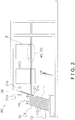
- FIG. 2 shows the case-making device 90.
- the case-making device 90 folds the box sheet S and forms a container box B in a state in which the upper flaps FU are opened.
- the case-making device 90 has a box-sheet-holding part 10, an extraction part 20, a case-opening part 30, a lower-flap-folding mechanism 40, and a tape-applying mechanism 50.
- the box-sheet-holding part 10 is a portion in which a group of box sheets S is placed.
- the box-sheet-holding part 10 has a support member 11 and a sheet-pushing mechanism 12.
- the support member 11 is a flat-plate-shaped member that supports the box sheets S.
- the support member 11 extends in a direction of standing upright (referred to as "upright direction UR" below), said direction having an incline of not less than 0° and not more than 30° relative to a vertical direction.
- the sheet-pushing mechanism 12 pushes the box sheet S with an appropriate force.
- the support member 11 is capable of withstanding the weight of the box sheets S and the force of the sheet-pushing mechanism.
- the box sheets S are held by the box-sheet-holding part 10 so as to extend in the upright direction UR.
- the extraction part 20 extracts one box sheet S that is the closest to the support member 11 from the group of box sheets S placed on the box-sheet-holding part 10.
- the extraction part 20 has a reciprocating member 21, a folding assist member 22, and a motor (not shown).
- the reciprocating member 21 is capable of reciprocating in the upright direction UR.
- a small hook part 21c for raising the one box sheet S is provided at a lower end of the reciprocating member 21.
- the motor raises or lowers the reciprocating member 21.
- the function of the folding assist member 22 is described later.
- the case-opening part 30 opens the box sheet S.
- the case-opening part 30 has a first suction tool 31a, a second suction tool 31b, an arm 32 ( FIG. 9 ), and a vacuum pump (not shown).
- the first suction tool 31a and the second suction tool 31b are made of a flexible soft material so as to be capable of closely fitting with the box sheet S.
- the first suction tool 31a is provided on the sheet-pushing-mechanism 12 side.
- the second suction tool 31b is provided on the reciprocating-member 21 side. At least one first suction tool 31a or at least one second suction tool 31b is provided on each side with reference to the box sheet S extracted by the extraction part 20.
- the first suction tool 31a and the second suction tool 31b are connected to the vacuum pump, and grip the surface of the box sheet S by suctioning air.
- the arm 32 opens the box sheet S by moving at least the second suction tool 31b.
- the lower-flap-folding mechanism 40 folds the lower flaps FL of the opened box sheet S and produces a bottom of the container box B.
- the tape-applying mechanism 50 applies adhesive tape to the folded lower flaps FL, thereby reinforcing the container box B.
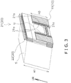
- FIG. 3 shows the box-sheet-holding part 10 holding a group of box sheets S.
- An upright-direction UR dimension of the box sheets S is a first dimension H1.
- Two support members 11 are provided to two width-direction end parts of the box sheets S.
- An upright-direction UR dimension of the support members 11 is a third dimension H3.
- the third dimension H3 is shorter than the first dimension H1.
- the reciprocating member 21 is provided between the two support members 11. According to this structure, the reciprocating member 21 is prevented from interfering with the support members 11.
- the hook part 21c provided at the lower end of the reciprocating member 21 is of such size as to raise only one box sheet S.
- the reciprocating member 21 has two column members 21a extending in the upright direction UR and one beam member 21b connecting the two column members. According to this structure, a space U that opens upward and is surrounded by the two column members 21a and the beam member 21b is formed in the reciprocating member 21.
- the folding assist member 22 is provided higher than the upper edge
- FIG. 4 shows the state of the box-sheet-holding part 10 when one box sheet S is extracted by the extraction part 20.
- the folding assist member 22 comes into contact with a crease C that defines a boundary between the wall parts W and the lower flaps FL of the box sheet S, or with the vicinity of the crease C.
- the first suction tool 31a and the second suction tool 31b of the case-opening part 30 approach the box sheet S from the two sides of the box sheet S. At this time, the second suction tool 31b comes into contact with the box sheet S in the aforementioned space U that opens upward.
- the reciprocating member 21 of the extraction part 20 raises one of the box sheets S placed on the box-sheet-holding part 10 by a second dimension H2 in the upright direction UR.
- the second dimension H2 is shorter than the first dimension H1.
- the folding assist member 22 comes into contact with the raised box sheet S at the crease C that defines the boundary between the wall parts W and the lower flaps FL, or in the vicinity of the crease C.
- the support members 11 extend by the third dimension H3 in the upright direction UR.
- the third dimension H3 is shorter than the second dimension H2.
- the raised box sheet S overlaps the group of box sheets S held by the box-sheet-holding part 10 over a fourth dimension H4 extending in the upright direction UR.
- the fourth dimension H4 is the difference between the first dimension H1 and the second dimension H2.
- the first suction tool 31a and the second suction tool 31b of the case-opening part 30 sandwich and grip the box sheet S.
- the second suction tool 31b comes into contact with the box sheet S through the space U.
- the folding assist member 22 supports the crease C of the box sheet S
- the box sheet S folds at the crease C.
- An upper-side portion of the box sheet S is gripped by the first suction tool 31a and the second suction tool 31b and extends in the vertical direction.
- a lower-side portion of the box sheet S is supported by the reciprocating member 21 and the folding assist member 22 and extends substantially in the upright direction UR.
- the lower-side portion of the box sheet S overlaps upper-side portions of the remaining box sheets S placed on the box-sheet-holding part 10.
- a difference in height between the upper edge EU of the box sheet S gripped by the first suction tool 31a and the second suction tool 31b and the lower edge EL of the group of box sheets S held by the box-sheet-holding part 10 is less than double the first dimension H1 of the box sheet S.
- the reciprocating member 21 of the extraction part 20 descends.
- the entirety of the box sheet S released from the support of the reciprocating member 21 extends in the vertical direction.
- the second suction tool 31b grips the box sheet S in the space U that opens upward, and therefore the reciprocating member 21 and the second suction tool 31b do not interfere with each other when the reciprocating member 21 descends.
- FIG. 9 is a plan view showing steps by which the box sheet S is opened.
- the first suction tool 31a grips a first surface of the box sheet S.
- the second suction tool 31b grips a second surface of the box sheet S that is on the opposite side from the first surface.
- the first suction tool 31a grips a wall part W that serves as a short edge of the container box B.
- the second suction tool 31b grips a wall part W that serves as a long edge of the container box B.
- the arm 32 moves the second suction tool 31b to thereby open the box sheet S.
- the one box sheet S extracted by the extraction part 20 partially overlaps the remaining box sheets S by the fourth dimension H4, which is the difference between the first dimension H1 and the second dimension H2.
- the box sheet S is opened and processed into a container box B. Therefore, because the box sheet S does not separate from the remaining box sheets S in the vertical direction when the box sheet S is opened, the height dimension of the case-making device 90 can be reduced.
- the box sheet S is placed on the box-sheet-holding part 10 so as to have a small inclination of not less than 0° and not more than 30° from the vertical direction. Therefore, because the group of box sheets S is supported by the support member 11 with a small force, the one box sheet S to be processed into a container box B is readily extracted.
- the extraction part 20 extracts only one box sheet S from the remaining box sheets S by raising the one box sheet S. Therefore, the structure of the extraction part is simple.
- the support member 11 of the box-sheet-holding part 10 supports a location over the third dimension H3 from the lower edge EL of the box sheet S.
- the third dimension H3 is shorter than the second dimension H2. Therefore, because the box sheet can be freely opened in a space equal to or greater than the second dimension H2, the height dimension of the case-making device can be reduced.
- the box sheet S is placed such that the upper flaps FU and the lower flaps FL are disposed on the upper and lower sides.
- the flap separation direction in a box sheet S is the same as the direction in which a short edge of the box sheet S extends. Therefore, because the short edge of the box sheet S extends upward and downward, the height dimension of the case-making device 90 can be reduced.
- the box sheet S is opened by the movement of the second suction tool 31b. Therefore, the box sheet S is processed into a container box B.
- Each of the first suction tool 31a and the second suction tool 31b grips a surface on opposing sides of the box sheet S. Therefore, the box sheet S is readily opened in a reliable manner.
- the box sheet S takes on an orientation along the vertical direction when gripped by the first suction tool 31a and the second suction tool 31b. Therefore, because a bottom edge of the container box B to be processed becomes horizontal, the container box B is easy to handle.
- the box sheet S gripped by the first suction tool 31a and the second suction tool 31b and the box sheets S held by the box-sheet-holding tool 10 do not separate in the height direction. Therefore, the height dimension of the case-making device 90 can be reduced.
- the crease C in the box sheet is used in changing the orientation of the box sheet S. Therefore, damage to the box sheet S can be suppressed.
- the structure of the reciprocating member 21 is not limited to only having two column members 21a and one beam member 21b. Other configurations may be employed, provided that there is a space U that opens upward.
- the structure of the support member 11 is not limited to being of a flat plate shape.
- a rod-shaped member, a lattice-shaped member, or another such structure may be employed, provided that the group of box sheets S can be stably supported.
Landscapes
- Engineering & Computer Science (AREA)
- Mechanical Engineering (AREA)
- Supplying Of Containers To The Packaging Station (AREA)
- Packaging Of Annular Or Rod-Shaped Articles, Wearing Apparel, Cassettes, Or The Like (AREA)
Abstract
Description
- The present invention relates to a case-making device.
- The case-making device disclosed in patent literature 1 (Japanese Laid-open Patent Publication No.
H6-199319 - Case-making devices are often bulky. Case-making devices especially tend to be tall, and therefore often cannot be placed in transport containers.
- The object of the present invention is to reduce a height dimension of a case-making device.
- A case-making device according to a first aspect of the present invention comprises a box-sheet-holding part and an extraction part. The box-sheet-holding part holds a plurality of box sheets to be processed into container boxes such that the box sheets extend in an upright direction. The extraction part extracts one of the box sheets from the box-sheet-holding part. An upright-direction dimension of the box sheet is a first dimension. The extraction part moves the box sheet in the upright direction by a second dimension shorter than the first dimension.
- According to this configuration, the one box sheet extracted by the extraction part partially overlaps remaining box sheets by the difference between the first dimension and the second dimension. The box sheet is opened in this state and processed into a container box. Therefore, because the box sheet does not separate from the remaining box sheets in a vertical direction when the box sheet is opened, a height dimension of the case-making device can be reduced.
- A case-making device according to a second aspect of the present invention is the case-making device according to the first aspect, wherein the upright direction is a direction that is inclined not less than 0° and not more than 30° from the vertical direction.
- According to this configuration, the box sheet is placed in the box-sheet-holding part so as to have a small inclination of not less than 0° and not more than 30° from the vertical direction. Therefore, because the group of box sheets is supported by the support member with a small force, the one box sheet to be processed into a container box is readily extracted.
- A case-making device according to a third aspect of the present invention is the case-making device according to the first or second aspect, wherein the extraction part raises the box sheet upward.
- According to this configuration, the extraction part extracts only the one box sheet from the remaining box sheets by raising the one box sheet. Therefore, the structure of the extraction part is simple.
- A case-making device according to a fourth aspect of the present invention is the case-making device according to any one of the first to third aspects, wherein the box-sheet-holding part has a support member to support a surface of the box sheet. The support member supports the box sheet within a range that is shorter than the second dimension from a lower edge of the box sheet.
- According to this configuration, the support member of the box-sheet-holding part supports the box sheet within a range that is shorter than the second dimension from the lower edge of the box sheet. Therefore, because the box sheet can be freely opened in a space beyond than the second dimension, the height dimension of the case-making device can be reduced.
- A case-making device according to a fifth aspect of the present invention is the case-making device according to any one of the first to fourth aspects, wherein the box sheet has flaps. The box sheet is placed in the box-sheet-holding part such that the flaps are disposed on an upper side and a lower side.
- According to this configuration, the box sheet is placed such that the flaps are disposed on the upper and lower sides. In many cases, the flap separation direction in a box sheet is the same as the direction in which a short edge of the box sheet extends. Therefore, because the short edge of the box sheet extends upward and downward, the height dimension of the case-making device can be reduced.
- A case-making device according to a sixth aspect of the present invention is the case-making device according to any one of the first to fifth aspects, wherein the case-making device further comprises a plurality of suction tools to grip the surface of the box sheet moved by the extraction part by suctioning air. At least some of the plurality of suction tools move, whereby the box sheet is opened.
- According to this configuration, the box sheet is opened by the movement of some of the suction tools. Therefore, the box sheet is processed into a container box.
- A case-making device according to a seventh aspect of the present invention is the case-making device according to the sixth aspect, wherein the plurality of suction tools includes a first suction tool to grip a first surface of the box sheet, and a second suction tool to grip a second surface of the box sheet that is on the opposite side from the first surface.
- According to this configuration, each of the first suction tool and the second suction tool grips a surface on opposing sides of the box sheet. Therefore, the box sheet is readily opened in a reliable manner.
- A case-making device according to an eighth aspect of the present invention is the case-making device according to the sixth or seventh aspect, wherein when a not-yet-opened box sheet is gripped by the plurality of suction tools, the box sheet takes on an orientation along the vertical direction.
- According to this configuration, the box sheet takes on an orientation along the vertical direction when gripped by the suction tools. Therefore, because a bottom edge of the container box to be assembled becomes horizontal, the container box is easy to handle.
- A case-making device according to a ninth aspect of the present invention is the case-making device according to any one of the sixth to eighth aspects, wherein a difference in height between an upper edge of the box sheet gripped by the suction tools and a lower edge of the box sheets held by the box-sheet-holding part is less than double the first dimension of the box sheet.
- According to this configuration, the box sheet gripped by the suction tools and the box sheets held by the box-sheet-holding part do not separate in the height direction. Therefore, the height dimension of the case-making device can be reduced.
- A case-making device according to a tenth aspect of the present invention is the case-making device according to any one of the sixth to ninth aspects, wherein when the extraction part supports the box sheet and the suction tools grip the box sheet, the box sheet folds at a crease sandwiched between a portion supported by the extraction part so as to follow the upright direction and a portion gripped by the suction tools so as to follow the vertical direction.
- According to this configuration, a crease in the box sheet is used in changing the orientation of the box sheet. Therefore, damage to the box sheet can be suppressed.
- The height dimension of the case-making device according to the present invention is small.
-
-
FIG. 1 is a schematic view of a box sheet S handled by a case-makingdevice 90 according to the present invention; -
FIG. 2 is a side view schematically showing a case-makingdevice 90 according to one embodiment of the present invention; -
FIG. 3 is a diagram of a box-sheet-holding part 10; -
FIG. 4 is a diagram of a box-sheet-holdingpart 10; -
FIG. 5 is a side view illustrating one step in a case-making operation; -
FIG. 6 is a side view illustrating one step in a case-making operation; -
FIG. 7 is a side view illustrating one step in a case-making operation; -
FIG. 8 is a side view illustrating one step in a case-making operation; and -
FIG. 9 is a plan view illustrating a case-making operation. - A case-making
device 90 according to one embodiment of the present invention is described with reference to the drawings. -
FIG. 1 shows a box sheet S handled by the case-making device 90. The box sheet S is made of cardboard. The box sheet has four wall parts W connected in a ring shape, and upper flaps FU and lower flaps FL that extend from the wall parts W. The upper flaps FU serve as a lid of a container box. The lower flaps FL serve as a bottom of the container box. Creases C are formed at the boundaries between adjacent wall parts W, at the boundaries between the wall parts W and the upper flaps FU, and at the boundaries between the wall parts W and the lower flaps FL. The box sheet S readily folds at the creases C. A distance between an upper edge EU and a lower edge EL of the box sheet S is a first dimension H1. -
FIG. 2 shows the case-makingdevice 90. The case-makingdevice 90 folds the box sheet S and forms a container box B in a state in which the upper flaps FU are opened. The case-makingdevice 90 has a box-sheet-holdingpart 10, anextraction part 20, a case-openingpart 30, a lower-flap-folding mechanism 40, and a tape-applying mechanism 50. - The box-sheet-holding
part 10 is a portion in which a group of box sheets S is placed. The box-sheet-holdingpart 10 has asupport member 11 and a sheet-pushingmechanism 12. Thesupport member 11 is a flat-plate-shaped member that supports the box sheets S. Thesupport member 11 extends in a direction of standing upright (referred to as "upright direction UR" below), said direction having an incline of not less than 0° and not more than 30° relative to a vertical direction. The sheet-pushingmechanism 12 pushes the box sheet S with an appropriate force. Thesupport member 11 is capable of withstanding the weight of the box sheets S and the force of the sheet-pushing mechanism. The box sheets S are held by the box-sheet-holdingpart 10 so as to extend in the upright direction UR. - The
extraction part 20 extracts one box sheet S that is the closest to thesupport member 11 from the group of box sheets S placed on the box-sheet-holdingpart 10. Theextraction part 20 has a reciprocatingmember 21, afolding assist member 22, and a motor (not shown). The reciprocatingmember 21 is capable of reciprocating in the upright direction UR. Asmall hook part 21c for raising the one box sheet S is provided at a lower end of the reciprocatingmember 21. The motor raises or lowers the reciprocatingmember 21. The function of the folding assistmember 22 is described later. - The case-opening
part 30 opens the box sheet S. The case-openingpart 30 has afirst suction tool 31a, asecond suction tool 31b, an arm 32 (FIG. 9 ), and a vacuum pump (not shown). Thefirst suction tool 31a and thesecond suction tool 31b are made of a flexible soft material so as to be capable of closely fitting with the box sheet S. Thefirst suction tool 31a is provided on the sheet-pushing-mechanism 12 side. Thesecond suction tool 31b is provided on the reciprocating-member 21 side. At least onefirst suction tool 31a or at least onesecond suction tool 31b is provided on each side with reference to the box sheet S extracted by theextraction part 20. Thefirst suction tool 31a and thesecond suction tool 31b are connected to the vacuum pump, and grip the surface of the box sheet S by suctioning air. Thearm 32 opens the box sheet S by moving at least thesecond suction tool 31b. - The lower-flap-folding mechanism 40 folds the lower flaps FL of the opened box sheet S and produces a bottom of the container box B.
- The tape-applying mechanism 50 applies adhesive tape to the folded lower flaps FL, thereby reinforcing the container box B.
-
FIG. 3 shows the box-sheet-holdingpart 10 holding a group of box sheets S. An upright-direction UR dimension of the box sheets S is a first dimension H1. Twosupport members 11 are provided to two width-direction end parts of the box sheets S. An upright-direction UR dimension of thesupport members 11 is a third dimension H3. The third dimension H3 is shorter than the first dimension H1. The reciprocatingmember 21 is provided between the twosupport members 11. According to this structure, the reciprocatingmember 21 is prevented from interfering with thesupport members 11. Thehook part 21c provided at the lower end of the reciprocatingmember 21 is of such size as to raise only one box sheet S. The reciprocatingmember 21 has twocolumn members 21a extending in the upright direction UR and onebeam member 21b connecting the two column members. According to this structure, a space U that opens upward and is surrounded by the twocolumn members 21a and thebeam member 21b is formed in the reciprocatingmember 21. Thefolding assist member 22 is provided higher than the upper edge EU of the box sheet S. -
FIG. 4 shows the state of the box-sheet-holdingpart 10 when one box sheet S is extracted by theextraction part 20. Thefolding assist member 22 comes into contact with a crease C that defines a boundary between the wall parts W and the lower flaps FL of the box sheet S, or with the vicinity of the crease C. Thefirst suction tool 31a and thesecond suction tool 31b of the case-openingpart 30 approach the box sheet S from the two sides of the box sheet S. At this time, thesecond suction tool 31b comes into contact with the box sheet S in the aforementioned space U that opens upward. - The steps by which the case-making
device 90 produces a container box B from the box sheet S are as described below. First, as shown inFIG. 5 , the reciprocatingmember 21 of theextraction part 20 raises one of the box sheets S placed on the box-sheet-holdingpart 10 by a second dimension H2 in the upright direction UR. The second dimension H2 is shorter than the first dimension H1. Thefolding assist member 22 comes into contact with the raised box sheet S at the crease C that defines the boundary between the wall parts W and the lower flaps FL, or in the vicinity of the crease C. Thesupport members 11 extend by the third dimension H3 in the upright direction UR. The third dimension H3 is shorter than the second dimension H2. The raised box sheet S overlaps the group of box sheets S held by the box-sheet-holdingpart 10 over a fourth dimension H4 extending in the upright direction UR. The fourth dimension H4 is the difference between the first dimension H1 and the second dimension H2. - Next, as shown in
FIG. 6 , thefirst suction tool 31a and thesecond suction tool 31b of the case-openingpart 30 sandwich and grip the box sheet S. Thesecond suction tool 31b comes into contact with the box sheet S through the space U. At this time, because the folding assistmember 22 supports the crease C of the box sheet S, the box sheet S folds at the crease C. An upper-side portion of the box sheet S is gripped by thefirst suction tool 31a and thesecond suction tool 31b and extends in the vertical direction. A lower-side portion of the box sheet S is supported by the reciprocatingmember 21 and the folding assistmember 22 and extends substantially in the upright direction UR. The lower-side portion of the box sheet S overlaps upper-side portions of the remaining box sheets S placed on the box-sheet-holdingpart 10. A difference in height between the upper edge EU of the box sheet S gripped by thefirst suction tool 31a and thesecond suction tool 31b and the lower edge EL of the group of box sheets S held by the box-sheet-holdingpart 10 is less than double the first dimension H1 of the box sheet S. - Next, as shown in
FIG. 7 , the reciprocatingmember 21 of theextraction part 20 descends. At this time, the entirety of the box sheet S released from the support of the reciprocatingmember 21 extends in the vertical direction. Thesecond suction tool 31b grips the box sheet S in the space U that opens upward, and therefore the reciprocatingmember 21 and thesecond suction tool 31b do not interfere with each other when the reciprocatingmember 21 descends. - Next, as shown in
FIG. 8 , thesecond suction tool 31b moves to thereby open the box sheet S.FIG. 9 is a plan view showing steps by which the box sheet S is opened. Thefirst suction tool 31a grips a first surface of the box sheet S. Thesecond suction tool 31b grips a second surface of the box sheet S that is on the opposite side from the first surface. Thefirst suction tool 31a grips a wall part W that serves as a short edge of the container box B. Thesecond suction tool 31b grips a wall part W that serves as a long edge of the container box B. Thearm 32 moves thesecond suction tool 31b to thereby open the box sheet S. - The one box sheet S extracted by the
extraction part 20 partially overlaps the remaining box sheets S by the fourth dimension H4, which is the difference between the first dimension H1 and the second dimension H2. In this state, the box sheet S is opened and processed into a container box B. Therefore, because the box sheet S does not separate from the remaining box sheets S in the vertical direction when the box sheet S is opened, the height dimension of the case-makingdevice 90 can be reduced. - The box sheet S is placed on the box-sheet-holding
part 10 so as to have a small inclination of not less than 0° and not more than 30° from the vertical direction. Therefore, because the group of box sheets S is supported by thesupport member 11 with a small force, the one box sheet S to be processed into a container box B is readily extracted. - The
extraction part 20 extracts only one box sheet S from the remaining box sheets S by raising the one box sheet S. Therefore, the structure of the extraction part is simple. - The
support member 11 of the box-sheet-holdingpart 10 supports a location over the third dimension H3 from the lower edge EL of the box sheet S. The third dimension H3 is shorter than the second dimension H2. Therefore, because the box sheet can be freely opened in a space equal to or greater than the second dimension H2, the height dimension of the case-making device can be reduced. - The box sheet S is placed such that the upper flaps FU and the lower flaps FL are disposed on the upper and lower sides. In many cases, the flap separation direction in a box sheet S is the same as the direction in which a short edge of the box sheet S extends. Therefore, because the short edge of the box sheet S extends upward and downward, the height dimension of the case-making
device 90 can be reduced. - The box sheet S is opened by the movement of the
second suction tool 31b. Therefore, the box sheet S is processed into a container box B. - Each of the
first suction tool 31a and thesecond suction tool 31b grips a surface on opposing sides of the box sheet S. Therefore, the box sheet S is readily opened in a reliable manner. - The box sheet S takes on an orientation along the vertical direction when gripped by the
first suction tool 31a and thesecond suction tool 31b. Therefore, because a bottom edge of the container box B to be processed becomes horizontal, the container box B is easy to handle. - The box sheet S gripped by the
first suction tool 31a and thesecond suction tool 31b and the box sheets S held by the box-sheet-holdingtool 10 do not separate in the height direction. Therefore, the height dimension of the case-makingdevice 90 can be reduced. - The crease C in the box sheet is used in changing the orientation of the box sheet S. Therefore, damage to the box sheet S can be suppressed.
- The structure of the reciprocating
member 21 is not limited to only having twocolumn members 21a and onebeam member 21b. Other configurations may be employed, provided that there is a space U that opens upward. - The structure of the
support member 11 is not limited to being of a flat plate shape. A rod-shaped member, a lattice-shaped member, or another such structure may be employed, provided that the group of box sheets S can be stably supported. -
- 10
- Box-sheet-holding part
- 11
- Support member
- 12
- Sheet-pushing mechanism
- 20
- Extraction part
- 21
- Reciprocating member
- 21a
- Column member
- 21b
- Beam member
- 21c
- Hook part
- 22
- Folding assist member
- 30
- Case-opening part
- 31a
- First suction tool
- 31b
- Second suction tool
- 32
- Arm
- 40
- Lower-flap-folding mechanism
- 50
- Tape-applying mechanism
- 90
- Case-making device
- B
- Container box
- C
- Crease
- EL
- Lower edge
- EU
- Upper edge
- FL
- Lower flap
- FU
- Upper flap
- H1
- First dimension
- H2
- Second dimension
- H3
- Third dimension
- H4
- Fourth dimension
- S
- Box sheet
- U
- Space
- UR
- Upright direction
- W
- Wall part
- Japanese Laid-open Patent Publication No.
H6-199319
Claims (10)
- A case-making device comprising:a box-sheet-holding part to hold a plurality of box sheets to be processed into container boxes such that the box sheets extend in an upright direction; andan extraction part to extract one of the box sheets from the box-sheet-holding part;an upright-direction dimension of the box sheet being a first dimension; andthe extraction part for moving the box sheet in the upright direction by a second dimension shorter than the first dimension.
- The case-making device according to claim 1, wherein
the upright direction is a direction that is inclined not less than 0° and not more than 30° from a vertical direction. - The case-making device according to claim 1 or 2, wherein
the extraction part raises the box sheet upward from below. - The case-making device according to any one of claims 1-3, wherein:the box-sheet-holding part has a support member to support a surface of the box sheet; andthe support member supports the box sheet within a range that is shorter than the second dimension from a lower edge of the box sheet.
- The case-making device according to any one of claims 1-4, wherein:the box sheet has flaps; andthe box sheet is placed in the box-sheet-holding part such that the flaps are disposed on an upper side and a lower side.
- The case-making device according to any one of claims 1-5, wherein:the case-making device furthermore comprises a plurality of suction tools to grip the surface of the box sheet moved by the extraction part by suctioning air; andat least some of the plurality of suction tools move, whereby the box sheet is opened.
- The case-making device according to claim 6, wherein the plurality of suction tools includes:a first suction tool to grip a first surface of the box sheet; anda second suction tool to grip a second surface of the box sheet that is on the opposite side from the first surface.
- The case-making device according to claim 6 or 7, wherein
when a not-yet-opened box sheet is gripped by the plurality of suction tools, the box sheet takes on an orientation along the vertical direction. - The case-making device according to any one of claims 6-8, wherein
a difference in height between an upper edge of the box sheet gripped by the suction tools and a lower edge of the box sheets held by the box-sheet-holding tool is less than double the first dimension of the box sheet. - The case-making device according to any one of claims 6-9, wherein
when the extraction part supports the box sheet and the suction tools grip the box sheet, the box sheet folds at a crease sandwiched between a portion supported by the extraction part so as to follow the upright direction and a portion gripped by the suction tools so as to follow the vertical direction.
Applications Claiming Priority (1)
| Application Number | Priority Date | Filing Date | Title |
|---|---|---|---|
| JP2017157940A JP6996734B2 (en) | 2017-08-18 | 2017-08-18 | Box making device |
Publications (2)
| Publication Number | Publication Date |
|---|---|
| EP3444109A1 true EP3444109A1 (en) | 2019-02-20 |
| EP3444109B1 EP3444109B1 (en) | 2022-03-09 |
Family
ID=63311793
Family Applications (1)
| Application Number | Title | Priority Date | Filing Date |
|---|---|---|---|
| EP18188745.6A Active EP3444109B1 (en) | 2017-08-18 | 2018-08-13 | Case-making device |
Country Status (5)
| Country | Link |
|---|---|
| US (1) | US11014322B2 (en) |
| EP (1) | EP3444109B1 (en) |
| JP (1) | JP6996734B2 (en) |
| CN (1) | CN109398819B (en) |
| AU (1) | AU2018217301B2 (en) |
Cited By (1)
| Publication number | Priority date | Publication date | Assignee | Title |
|---|---|---|---|---|
| KR20230026820A (en) * | 2021-08-18 | 2023-02-27 | 강형석 | Automatic fabric feeder for packaging materials |
Families Citing this family (3)
| Publication number | Priority date | Publication date | Assignee | Title |
|---|---|---|---|---|
| CA3021452A1 (en) * | 2018-10-17 | 2020-04-17 | Thatbox Design, Llc | Improved manufacturing methods and apparatus for containers and packaging |
| US20220363421A1 (en) * | 2019-09-27 | 2022-11-17 | Daio Paper Corporation | Corrugated cardboard box making device, box making method, and box making and processing method |
| CN114735313B (en) * | 2021-11-29 | 2023-12-15 | 郑州旺丰元纸制品有限公司 | Automatic production line for processing cartons by using paperboards |
Citations (6)
| Publication number | Priority date | Publication date | Assignee | Title |
|---|---|---|---|---|
| DE2155230A1 (en) * | 1971-11-06 | 1973-05-10 | Enzinger Union Werke Ag | METHOD AND DEVICE FOR UNFOLDING FLAT PRE-MADE CARTONS |
| US4201118A (en) * | 1978-11-24 | 1980-05-06 | The Mead Corporation | Machine for manipulating a collapsed basket style carton into set-up condition and for adhering end flaps to end panels at each end of the carton |
| US4348853A (en) * | 1980-08-08 | 1982-09-14 | Morse Hugh B | Case opening and sealing apparatus |
| JPH06199319A (en) | 1992-12-28 | 1994-07-19 | Mitsui Matsushima Co Ltd | Device for opening carton case |
| JPH0858735A (en) * | 1994-08-19 | 1996-03-05 | Kawashima Packaging Mach Ltd | Corrugated fiberboard box making method |
| JP2014061635A (en) * | 2012-09-20 | 2014-04-10 | Ishida Co Ltd | Box making device |
Family Cites Families (24)
| Publication number | Priority date | Publication date | Assignee | Title |
|---|---|---|---|---|
| US2782695A (en) * | 1954-06-18 | 1957-02-26 | American Viscose Corp | Carton set-up machine |
| US3420036A (en) * | 1966-03-18 | 1969-01-07 | Elizabeth B Hutchinson | Carton handling system and apparatus |
| US3564980A (en) | 1968-11-21 | 1971-02-23 | John Donald Winters | Container set-up apparatus |
| US3613526A (en) * | 1969-05-09 | 1971-10-19 | Jones & Co Inc R A | Carton feeding and erecting apparatus |
| US3828659A (en) * | 1972-02-01 | 1974-08-13 | Abc Packaging Machine Corp | Method of folding a box blank |
| US3859896A (en) * | 1973-04-03 | 1975-01-14 | D & B Machine Co | Vertical carton erector |
| US4041850A (en) * | 1974-08-09 | 1977-08-16 | Abc Packaging Machine Corporation | Method of erecting carton blanks |
| US4441377A (en) * | 1979-12-05 | 1984-04-10 | International Paper Company | Linkage for actuating a carton erecting apparatus |
| SE457634B (en) * | 1986-04-18 | 1989-01-16 | Tetra Pak Ab | DEVICE FOR RISKING OF THE PACKAGING CONTAINERS |
| US5186706A (en) * | 1990-09-10 | 1993-02-16 | Hartness International, Inc. | Carton erecting machine |
| US5393291A (en) * | 1993-07-08 | 1995-02-28 | Marq Packaging Systems, Inc. | Mini case erector |
| IT1273796B (en) * | 1994-02-08 | 1997-07-10 | Ima Spa | METHOD AND DEVICE FOR THE COLLECTION AND FEEDING OF ENVELOPES STORED IN A FLAT FORM |
| JPH107108A (en) * | 1996-06-20 | 1998-01-13 | Kawashima Packaging Mach Ltd | Box making equipment for cardboard boxes |
| US6669616B1 (en) * | 2000-09-26 | 2003-12-30 | Illinois Tool Works Inc. | Compact case forming machine |
| ITBO20020379A1 (en) * | 2002-06-13 | 2003-12-15 | Gd Spa | METHOD AND MACHINE FOR THE PACKAGING OF A PRODUCT USING A FLAT TUBULAR WRAPPING |
| JP3693998B2 (en) * | 2003-02-06 | 2005-09-14 | 株式会社ナミックス | Cartoning machine |
| JP4756866B2 (en) * | 2005-01-14 | 2011-08-24 | 株式会社ユニテック | Opening device |
| CN200970901Y (en) * | 2006-05-23 | 2007-11-07 | 广州市万世德包装机械有限公司 | Carton forming machine |
| CN201471786U (en) * | 2009-07-30 | 2010-05-19 | 杭州松源机械制造有限公司 | Carton separation device of carton making machine |
| JP6052861B2 (en) | 2012-09-20 | 2016-12-27 | 株式会社イシダ | Boxing equipment |
| JP6038566B2 (en) * | 2012-09-20 | 2016-12-07 | 株式会社イシダ | Box making equipment |
| JP6463147B2 (en) * | 2015-01-23 | 2019-01-30 | 株式会社イシダ | Boxing equipment |
| JP6262173B2 (en) | 2015-06-30 | 2018-01-17 | 株式会社フジキカイ | Box making equipment |
| CN106005532A (en) * | 2016-06-27 | 2016-10-12 | 应金宝 | Automatic unfolding feeding device and method for cigarette cases |
-
2017
- 2017-08-18 JP JP2017157940A patent/JP6996734B2/en active Active
-
2018
- 2018-08-10 US US16/100,203 patent/US11014322B2/en active Active
- 2018-08-13 EP EP18188745.6A patent/EP3444109B1/en active Active
- 2018-08-16 CN CN201810938237.2A patent/CN109398819B/en active Active
- 2018-08-17 AU AU2018217301A patent/AU2018217301B2/en active Active
Patent Citations (6)
| Publication number | Priority date | Publication date | Assignee | Title |
|---|---|---|---|---|
| DE2155230A1 (en) * | 1971-11-06 | 1973-05-10 | Enzinger Union Werke Ag | METHOD AND DEVICE FOR UNFOLDING FLAT PRE-MADE CARTONS |
| US4201118A (en) * | 1978-11-24 | 1980-05-06 | The Mead Corporation | Machine for manipulating a collapsed basket style carton into set-up condition and for adhering end flaps to end panels at each end of the carton |
| US4348853A (en) * | 1980-08-08 | 1982-09-14 | Morse Hugh B | Case opening and sealing apparatus |
| JPH06199319A (en) | 1992-12-28 | 1994-07-19 | Mitsui Matsushima Co Ltd | Device for opening carton case |
| JPH0858735A (en) * | 1994-08-19 | 1996-03-05 | Kawashima Packaging Mach Ltd | Corrugated fiberboard box making method |
| JP2014061635A (en) * | 2012-09-20 | 2014-04-10 | Ishida Co Ltd | Box making device |
Cited By (1)
| Publication number | Priority date | Publication date | Assignee | Title |
|---|---|---|---|---|
| KR20230026820A (en) * | 2021-08-18 | 2023-02-27 | 강형석 | Automatic fabric feeder for packaging materials |
Also Published As
| Publication number | Publication date |
|---|---|
| JP6996734B2 (en) | 2022-01-17 |
| CN109398819B (en) | 2020-12-18 |
| US11014322B2 (en) | 2021-05-25 |
| AU2018217301A1 (en) | 2019-03-07 |
| JP2019034770A (en) | 2019-03-07 |
| US20190054713A1 (en) | 2019-02-21 |
| EP3444109B1 (en) | 2022-03-09 |
| CN109398819A (en) | 2019-03-01 |
| AU2018217301B2 (en) | 2019-12-05 |
Similar Documents
| Publication | Publication Date | Title |
|---|---|---|
| EP3444109B1 (en) | Case-making device | |
| US11345499B2 (en) | Packaging apparatus, removal apparatus and method for withdrawing a cardboard blank | |
| EP3592650B1 (en) | A box erecting method and system | |
| US10093446B2 (en) | Blanks and methods for forming containers having stacking platforms | |
| US20060100079A1 (en) | Methods and apparatus for forming a container | |
| US20130232918A1 (en) | Method of Forming U-Shaped Insert and Inserting About Goods in Container | |
| CN103253404A (en) | Integrated machine for unsealing and sealing carton box | |
| CN102574352A (en) | Method for assembling a cardboard cutout, and equipment for implementing same | |
| CN111824511A (en) | Vertical product packaging equipment and packaging method | |
| ITRE20100016A1 (en) | EQUIPMENT AND METHOD FOR FORMATION OF EDGED TRAYS | |
| JPH08183517A (en) | Boxing equipment | |
| CN213109888U (en) | A carton packaging machine | |
| CN221835646U (en) | Blister box packing equipment | |
| CN217575829U (en) | Full-automatic unsealing all-in-one machine for putting articles into box | |
| CN112319968B (en) | A grabbing device for tearing open tobacco leaf packing outer container | |
| EP3819240B1 (en) | A carboard packer, and a method for transporting a blank | |
| CN207450383U (en) | A stacking packaging device for packaging boxes | |
| CN209814430U (en) | Vertical product packaging equipment | |
| CN209651393U (en) | A kind of separating mechanism | |
| CN220221315U (en) | Boxing mechanism | |
| TWI834106B (en) | Folding box module and packing system | |
| CN218478276U (en) | Material conveying system | |
| US12263975B2 (en) | Method of automating filling and packaging of flat retention inserts | |
| CN219903547U (en) | Automatic forming paper folding box device | |
| KR102962351B1 (en) | Paperboard forming machine and box manufacturing equipment |
Legal Events
| Date | Code | Title | Description |
|---|---|---|---|
| PUAI | Public reference made under article 153(3) epc to a published international application that has entered the european phase |
Free format text: ORIGINAL CODE: 0009012 |
|
| STAA | Information on the status of an ep patent application or granted ep patent |
Free format text: STATUS: THE APPLICATION HAS BEEN PUBLISHED |
|
| AK | Designated contracting states |
Kind code of ref document: A1 Designated state(s): AL AT BE BG CH CY CZ DE DK EE ES FI FR GB GR HR HU IE IS IT LI LT LU LV MC MK MT NL NO PL PT RO RS SE SI SK SM TR |
|
| AX | Request for extension of the european patent |
Extension state: BA ME |
|
| STAA | Information on the status of an ep patent application or granted ep patent |
Free format text: STATUS: REQUEST FOR EXAMINATION WAS MADE |
|
| 17P | Request for examination filed |
Effective date: 20190814 |
|
| RBV | Designated contracting states (corrected) |
Designated state(s): AL AT BE BG CH CY CZ DE DK EE ES FI FR GB GR HR HU IE IS IT LI LT LU LV MC MK MT NL NO PL PT RO RS SE SI SK SM TR |
|
| STAA | Information on the status of an ep patent application or granted ep patent |
Free format text: STATUS: EXAMINATION IS IN PROGRESS |
|
| 17Q | First examination report despatched |
Effective date: 20191210 |
|
| GRAP | Despatch of communication of intention to grant a patent |
Free format text: ORIGINAL CODE: EPIDOSNIGR1 |
|
| STAA | Information on the status of an ep patent application or granted ep patent |
Free format text: STATUS: GRANT OF PATENT IS INTENDED |
|
| RIC1 | Information provided on ipc code assigned before grant |
Ipc: B31B 50/80 20170101ALI20200720BHEP Ipc: B31B 120/30 20170101ALN20200720BHEP Ipc: B31B 50/06 20170101AFI20200720BHEP Ipc: B31B 100/00 20170101ALN20200720BHEP |
|
| INTG | Intention to grant announced |
Effective date: 20200818 |
|
| GRAJ | Information related to disapproval of communication of intention to grant by the applicant or resumption of examination proceedings by the epo deleted |
Free format text: ORIGINAL CODE: EPIDOSDIGR1 |
|
| STAA | Information on the status of an ep patent application or granted ep patent |
Free format text: STATUS: EXAMINATION IS IN PROGRESS |
|
| INTC | Intention to grant announced (deleted) | ||
| GRAP | Despatch of communication of intention to grant a patent |
Free format text: ORIGINAL CODE: EPIDOSNIGR1 |
|
| STAA | Information on the status of an ep patent application or granted ep patent |
Free format text: STATUS: GRANT OF PATENT IS INTENDED |
|
| RIC1 | Information provided on ipc code assigned before grant |
Ipc: B31B 120/30 20170101ALN20211027BHEP Ipc: B31B 100/00 20170101ALN20211027BHEP Ipc: B31B 50/80 20170101ALI20211027BHEP Ipc: B31B 50/06 20170101AFI20211027BHEP |
|
| INTG | Intention to grant announced |
Effective date: 20211117 |
|
| GRAS | Grant fee paid |
Free format text: ORIGINAL CODE: EPIDOSNIGR3 |
|
| GRAA | (expected) grant |
Free format text: ORIGINAL CODE: 0009210 |
|
| STAA | Information on the status of an ep patent application or granted ep patent |
Free format text: STATUS: THE PATENT HAS BEEN GRANTED |
|
| AK | Designated contracting states |
Kind code of ref document: B1 Designated state(s): AL AT BE BG CH CY CZ DE DK EE ES FI FR GB GR HR HU IE IS IT LI LT LU LV MC MK MT NL NO PL PT RO RS SE SI SK SM TR |
|
| REG | Reference to a national code |
Ref country code: CH Ref legal event code: EP Ref country code: AT Ref legal event code: REF Ref document number: 1473777 Country of ref document: AT Kind code of ref document: T Effective date: 20220315 |
|
| REG | Reference to a national code |
Ref country code: IE Ref legal event code: FG4D |
|
| REG | Reference to a national code |
Ref country code: DE Ref legal event code: R096 Ref document number: 602018031872 Country of ref document: DE |
|
| REG | Reference to a national code |
Ref country code: NL Ref legal event code: FP |
|
| REG | Reference to a national code |
Ref country code: NO Ref legal event code: T2 Effective date: 20220309 |
|
| REG | Reference to a national code |
Ref country code: LT Ref legal event code: MG9D |
|
| PG25 | Lapsed in a contracting state [announced via postgrant information from national office to epo] |
Ref country code: SE Free format text: LAPSE BECAUSE OF FAILURE TO SUBMIT A TRANSLATION OF THE DESCRIPTION OR TO PAY THE FEE WITHIN THE PRESCRIBED TIME-LIMIT Effective date: 20220309 Ref country code: RS Free format text: LAPSE BECAUSE OF FAILURE TO SUBMIT A TRANSLATION OF THE DESCRIPTION OR TO PAY THE FEE WITHIN THE PRESCRIBED TIME-LIMIT Effective date: 20220309 Ref country code: LT Free format text: LAPSE BECAUSE OF FAILURE TO SUBMIT A TRANSLATION OF THE DESCRIPTION OR TO PAY THE FEE WITHIN THE PRESCRIBED TIME-LIMIT Effective date: 20220309 Ref country code: HR Free format text: LAPSE BECAUSE OF FAILURE TO SUBMIT A TRANSLATION OF THE DESCRIPTION OR TO PAY THE FEE WITHIN THE PRESCRIBED TIME-LIMIT Effective date: 20220309 Ref country code: BG Free format text: LAPSE BECAUSE OF FAILURE TO SUBMIT A TRANSLATION OF THE DESCRIPTION OR TO PAY THE FEE WITHIN THE PRESCRIBED TIME-LIMIT Effective date: 20220609 |
|
| REG | Reference to a national code |
Ref country code: AT Ref legal event code: MK05 Ref document number: 1473777 Country of ref document: AT Kind code of ref document: T Effective date: 20220309 |
|
| PG25 | Lapsed in a contracting state [announced via postgrant information from national office to epo] |
Ref country code: LV Free format text: LAPSE BECAUSE OF FAILURE TO SUBMIT A TRANSLATION OF THE DESCRIPTION OR TO PAY THE FEE WITHIN THE PRESCRIBED TIME-LIMIT Effective date: 20220309 Ref country code: GR Free format text: LAPSE BECAUSE OF FAILURE TO SUBMIT A TRANSLATION OF THE DESCRIPTION OR TO PAY THE FEE WITHIN THE PRESCRIBED TIME-LIMIT Effective date: 20220610 Ref country code: FI Free format text: LAPSE BECAUSE OF FAILURE TO SUBMIT A TRANSLATION OF THE DESCRIPTION OR TO PAY THE FEE WITHIN THE PRESCRIBED TIME-LIMIT Effective date: 20220309 |
|
| PG25 | Lapsed in a contracting state [announced via postgrant information from national office to epo] |
Ref country code: SM Free format text: LAPSE BECAUSE OF FAILURE TO SUBMIT A TRANSLATION OF THE DESCRIPTION OR TO PAY THE FEE WITHIN THE PRESCRIBED TIME-LIMIT Effective date: 20220309 Ref country code: SK Free format text: LAPSE BECAUSE OF FAILURE TO SUBMIT A TRANSLATION OF THE DESCRIPTION OR TO PAY THE FEE WITHIN THE PRESCRIBED TIME-LIMIT Effective date: 20220309 Ref country code: RO Free format text: LAPSE BECAUSE OF FAILURE TO SUBMIT A TRANSLATION OF THE DESCRIPTION OR TO PAY THE FEE WITHIN THE PRESCRIBED TIME-LIMIT Effective date: 20220309 Ref country code: PT Free format text: LAPSE BECAUSE OF FAILURE TO SUBMIT A TRANSLATION OF THE DESCRIPTION OR TO PAY THE FEE WITHIN THE PRESCRIBED TIME-LIMIT Effective date: 20220711 Ref country code: ES Free format text: LAPSE BECAUSE OF FAILURE TO SUBMIT A TRANSLATION OF THE DESCRIPTION OR TO PAY THE FEE WITHIN THE PRESCRIBED TIME-LIMIT Effective date: 20220309 Ref country code: EE Free format text: LAPSE BECAUSE OF FAILURE TO SUBMIT A TRANSLATION OF THE DESCRIPTION OR TO PAY THE FEE WITHIN THE PRESCRIBED TIME-LIMIT Effective date: 20220309 Ref country code: CZ Free format text: LAPSE BECAUSE OF FAILURE TO SUBMIT A TRANSLATION OF THE DESCRIPTION OR TO PAY THE FEE WITHIN THE PRESCRIBED TIME-LIMIT Effective date: 20220309 Ref country code: AT Free format text: LAPSE BECAUSE OF FAILURE TO SUBMIT A TRANSLATION OF THE DESCRIPTION OR TO PAY THE FEE WITHIN THE PRESCRIBED TIME-LIMIT Effective date: 20220309 |
|
| PG25 | Lapsed in a contracting state [announced via postgrant information from national office to epo] |
Ref country code: PL Free format text: LAPSE BECAUSE OF FAILURE TO SUBMIT A TRANSLATION OF THE DESCRIPTION OR TO PAY THE FEE WITHIN THE PRESCRIBED TIME-LIMIT Effective date: 20220309 Ref country code: IS Free format text: LAPSE BECAUSE OF FAILURE TO SUBMIT A TRANSLATION OF THE DESCRIPTION OR TO PAY THE FEE WITHIN THE PRESCRIBED TIME-LIMIT Effective date: 20220709 Ref country code: AL Free format text: LAPSE BECAUSE OF FAILURE TO SUBMIT A TRANSLATION OF THE DESCRIPTION OR TO PAY THE FEE WITHIN THE PRESCRIBED TIME-LIMIT Effective date: 20220309 |
|
| REG | Reference to a national code |
Ref country code: DE Ref legal event code: R097 Ref document number: 602018031872 Country of ref document: DE |
|
| PLBE | No opposition filed within time limit |
Free format text: ORIGINAL CODE: 0009261 |
|
| STAA | Information on the status of an ep patent application or granted ep patent |
Free format text: STATUS: NO OPPOSITION FILED WITHIN TIME LIMIT |
|
| PG25 | Lapsed in a contracting state [announced via postgrant information from national office to epo] |
Ref country code: DK Free format text: LAPSE BECAUSE OF FAILURE TO SUBMIT A TRANSLATION OF THE DESCRIPTION OR TO PAY THE FEE WITHIN THE PRESCRIBED TIME-LIMIT Effective date: 20220309 |
|
| 26N | No opposition filed |
Effective date: 20221212 |
|
| PG25 | Lapsed in a contracting state [announced via postgrant information from national office to epo] |
Ref country code: SI Free format text: LAPSE BECAUSE OF FAILURE TO SUBMIT A TRANSLATION OF THE DESCRIPTION OR TO PAY THE FEE WITHIN THE PRESCRIBED TIME-LIMIT Effective date: 20220309 |
|
| PG25 | Lapsed in a contracting state [announced via postgrant information from national office to epo] |
Ref country code: MC Free format text: LAPSE BECAUSE OF FAILURE TO SUBMIT A TRANSLATION OF THE DESCRIPTION OR TO PAY THE FEE WITHIN THE PRESCRIBED TIME-LIMIT Effective date: 20220309 |
|
| REG | Reference to a national code |
Ref country code: CH Ref legal event code: PL |
|
| PG25 | Lapsed in a contracting state [announced via postgrant information from national office to epo] |
Ref country code: LU Free format text: LAPSE BECAUSE OF NON-PAYMENT OF DUE FEES Effective date: 20220813 Ref country code: LI Free format text: LAPSE BECAUSE OF NON-PAYMENT OF DUE FEES Effective date: 20220831 Ref country code: CH Free format text: LAPSE BECAUSE OF NON-PAYMENT OF DUE FEES Effective date: 20220831 |
|
| REG | Reference to a national code |
Ref country code: BE Ref legal event code: MM Effective date: 20220831 |
|
| PG25 | Lapsed in a contracting state [announced via postgrant information from national office to epo] |
Ref country code: IT Free format text: LAPSE BECAUSE OF FAILURE TO SUBMIT A TRANSLATION OF THE DESCRIPTION OR TO PAY THE FEE WITHIN THE PRESCRIBED TIME-LIMIT Effective date: 20220309 Ref country code: IE Free format text: LAPSE BECAUSE OF NON-PAYMENT OF DUE FEES Effective date: 20220813 Ref country code: FR Free format text: LAPSE BECAUSE OF NON-PAYMENT OF DUE FEES Effective date: 20220831 |
|
| PG25 | Lapsed in a contracting state [announced via postgrant information from national office to epo] |
Ref country code: BE Free format text: LAPSE BECAUSE OF NON-PAYMENT OF DUE FEES Effective date: 20220831 |
|
| PG25 | Lapsed in a contracting state [announced via postgrant information from national office to epo] |
Ref country code: HU Free format text: LAPSE BECAUSE OF FAILURE TO SUBMIT A TRANSLATION OF THE DESCRIPTION OR TO PAY THE FEE WITHIN THE PRESCRIBED TIME-LIMIT; INVALID AB INITIO Effective date: 20180813 |
|
| PG25 | Lapsed in a contracting state [announced via postgrant information from national office to epo] |
Ref country code: CY Free format text: LAPSE BECAUSE OF FAILURE TO SUBMIT A TRANSLATION OF THE DESCRIPTION OR TO PAY THE FEE WITHIN THE PRESCRIBED TIME-LIMIT Effective date: 20220309 |
|
| PG25 | Lapsed in a contracting state [announced via postgrant information from national office to epo] |
Ref country code: MK Free format text: LAPSE BECAUSE OF FAILURE TO SUBMIT A TRANSLATION OF THE DESCRIPTION OR TO PAY THE FEE WITHIN THE PRESCRIBED TIME-LIMIT Effective date: 20220309 |
|
| PG25 | Lapsed in a contracting state [announced via postgrant information from national office to epo] |
Ref country code: MT Free format text: LAPSE BECAUSE OF FAILURE TO SUBMIT A TRANSLATION OF THE DESCRIPTION OR TO PAY THE FEE WITHIN THE PRESCRIBED TIME-LIMIT Effective date: 20220309 |
|
| PGFP | Annual fee paid to national office [announced via postgrant information from national office to epo] |
Ref country code: NL Payment date: 20250821 Year of fee payment: 8 |
|
| PGFP | Annual fee paid to national office [announced via postgrant information from national office to epo] |
Ref country code: DE Payment date: 20250819 Year of fee payment: 8 |
|
| PGFP | Annual fee paid to national office [announced via postgrant information from national office to epo] |
Ref country code: NO Payment date: 20250820 Year of fee payment: 8 |
|
| PGFP | Annual fee paid to national office [announced via postgrant information from national office to epo] |
Ref country code: GB Payment date: 20250822 Year of fee payment: 8 |
|
| PG25 | Lapsed in a contracting state [announced via postgrant information from national office to epo] |
Ref country code: TR Free format text: LAPSE BECAUSE OF FAILURE TO SUBMIT A TRANSLATION OF THE DESCRIPTION OR TO PAY THE FEE WITHIN THE PRESCRIBED TIME-LIMIT Effective date: 20220309 |