EP3442445B1 - Pièce à main chirurgicale et système de moyeu de verrouillage - Google Patents
Pièce à main chirurgicale et système de moyeu de verrouillage Download PDFInfo
- Publication number
- EP3442445B1 EP3442445B1 EP17720643.0A EP17720643A EP3442445B1 EP 3442445 B1 EP3442445 B1 EP 3442445B1 EP 17720643 A EP17720643 A EP 17720643A EP 3442445 B1 EP3442445 B1 EP 3442445B1
- Authority
- EP
- European Patent Office
- Prior art keywords
- hub
- drive unit
- latch
- perimeter
- longitudinal axis
- Prior art date
- Legal status (The legal status is an assumption and is not a legal conclusion. Google has not performed a legal analysis and makes no representation as to the accuracy of the status listed.)
- Active
Links
- 239000012530 fluid Substances 0.000 description 19
- 230000007246 mechanism Effects 0.000 description 9
- 238000002271 resection Methods 0.000 description 9
- 239000002699 waste material Substances 0.000 description 6
- 239000000463 material Substances 0.000 description 5
- 230000008878 coupling Effects 0.000 description 4
- 238000010168 coupling process Methods 0.000 description 4
- 238000005859 coupling reaction Methods 0.000 description 4
- 229920000642 polymer Polymers 0.000 description 4
- 238000000926 separation method Methods 0.000 description 4
- 229910052751 metal Inorganic materials 0.000 description 3
- 239000002184 metal Substances 0.000 description 3
- WOBHKFSMXKNTIM-UHFFFAOYSA-N Hydroxyethyl methacrylate Chemical compound CC(=C)C(=O)OCCO WOBHKFSMXKNTIM-UHFFFAOYSA-N 0.000 description 2
- 239000004696 Poly ether ether ketone Substances 0.000 description 2
- 239000004698 Polyethylene Substances 0.000 description 2
- FAPWRFPIFSIZLT-UHFFFAOYSA-M Sodium chloride Chemical compound [Na+].[Cl-] FAPWRFPIFSIZLT-UHFFFAOYSA-M 0.000 description 2
- QCWXUUIWCKQGHC-UHFFFAOYSA-N Zirconium Chemical compound [Zr] QCWXUUIWCKQGHC-UHFFFAOYSA-N 0.000 description 2
- 239000000853 adhesive Substances 0.000 description 2
- 230000001070 adhesive effect Effects 0.000 description 2
- 239000000560 biocompatible material Substances 0.000 description 2
- 238000002674 endoscopic surgery Methods 0.000 description 2
- 150000002739 metals Chemical class 0.000 description 2
- 229920001652 poly(etherketoneketone) Polymers 0.000 description 2
- 229920003229 poly(methyl methacrylate) Polymers 0.000 description 2
- 229920002530 polyetherether ketone Polymers 0.000 description 2
- -1 polyethylene Polymers 0.000 description 2
- 229920000573 polyethylene Polymers 0.000 description 2
- 239000004926 polymethyl methacrylate Substances 0.000 description 2
- 239000011780 sodium chloride Substances 0.000 description 2
- 229910052726 zirconium Inorganic materials 0.000 description 2
- 229920002818 (Hydroxyethyl)methacrylate Polymers 0.000 description 1
- 229910000851 Alloy steel Inorganic materials 0.000 description 1
- OKTJSMMVPCPJKN-UHFFFAOYSA-N Carbon Chemical compound [C] OKTJSMMVPCPJKN-UHFFFAOYSA-N 0.000 description 1
- 229910000684 Cobalt-chrome Inorganic materials 0.000 description 1
- 229910000990 Ni alloy Inorganic materials 0.000 description 1
- 239000004952 Polyamide Substances 0.000 description 1
- 229910001069 Ti alloy Inorganic materials 0.000 description 1
- RTAQQCXQSZGOHL-UHFFFAOYSA-N Titanium Chemical compound [Ti] RTAQQCXQSZGOHL-UHFFFAOYSA-N 0.000 description 1
- HZEWFHLRYVTOIW-UHFFFAOYSA-N [Ti].[Ni] Chemical compound [Ti].[Ni] HZEWFHLRYVTOIW-UHFFFAOYSA-N 0.000 description 1
- 239000003082 abrasive agent Substances 0.000 description 1
- 230000009471 action Effects 0.000 description 1
- 229910045601 alloy Inorganic materials 0.000 description 1
- 239000000956 alloy Substances 0.000 description 1
- 230000008901 benefit Effects 0.000 description 1
- 229920000249 biocompatible polymer Polymers 0.000 description 1
- 239000003990 capacitor Substances 0.000 description 1
- 229910052799 carbon Inorganic materials 0.000 description 1
- 239000000919 ceramic Substances 0.000 description 1
- 238000004140 cleaning Methods 0.000 description 1
- 239000010952 cobalt-chrome Substances 0.000 description 1
- 229920003020 cross-linked polyethylene Polymers 0.000 description 1
- 239000004703 cross-linked polyethylene Substances 0.000 description 1
- 238000010586 diagram Methods 0.000 description 1
- 230000005611 electricity Effects 0.000 description 1
- 238000012976 endoscopic surgical procedure Methods 0.000 description 1
- 239000011521 glass Substances 0.000 description 1
- 229920001684 low density polyethylene Polymers 0.000 description 1
- 239000004702 low-density polyethylene Substances 0.000 description 1
- 230000013011 mating Effects 0.000 description 1
- 229910001092 metal group alloy Inorganic materials 0.000 description 1
- 229910001000 nickel titanium Inorganic materials 0.000 description 1
- HLXZNVUGXRDIFK-UHFFFAOYSA-N nickel titanium Chemical compound [Ti].[Ti].[Ti].[Ti].[Ti].[Ti].[Ti].[Ti].[Ti].[Ti].[Ti].[Ni].[Ni].[Ni].[Ni].[Ni].[Ni].[Ni].[Ni].[Ni].[Ni].[Ni].[Ni].[Ni].[Ni] HLXZNVUGXRDIFK-UHFFFAOYSA-N 0.000 description 1
- 230000037361 pathway Effects 0.000 description 1
- 229920002647 polyamide Polymers 0.000 description 1
- 239000002861 polymer material Substances 0.000 description 1
- 229920002635 polyurethane Polymers 0.000 description 1
- 239000004814 polyurethane Substances 0.000 description 1
- 238000003825 pressing Methods 0.000 description 1
- 230000003014 reinforcing effect Effects 0.000 description 1
- 239000011347 resin Substances 0.000 description 1
- 229920005989 resin Polymers 0.000 description 1
- 239000010935 stainless steel Substances 0.000 description 1
- 229910001220 stainless steel Inorganic materials 0.000 description 1
- 229910052715 tantalum Inorganic materials 0.000 description 1
- GUVRBAGPIYLISA-UHFFFAOYSA-N tantalum atom Chemical compound [Ta] GUVRBAGPIYLISA-UHFFFAOYSA-N 0.000 description 1
- 239000010936 titanium Substances 0.000 description 1
- 229910052719 titanium Inorganic materials 0.000 description 1
Images


Classifications
-
- A—HUMAN NECESSITIES
- A61—MEDICAL OR VETERINARY SCIENCE; HYGIENE
- A61B—DIAGNOSIS; SURGERY; IDENTIFICATION
- A61B17/00—Surgical instruments, devices or methods, e.g. tourniquets
- A61B17/32—Surgical cutting instruments
- A61B17/320016—Endoscopic cutting instruments, e.g. arthroscopes, resectoscopes
- A61B17/32002—Endoscopic cutting instruments, e.g. arthroscopes, resectoscopes with continuously rotating, oscillating or reciprocating cutting instruments
-
- A—HUMAN NECESSITIES
- A61—MEDICAL OR VETERINARY SCIENCE; HYGIENE
- A61B—DIAGNOSIS; SURGERY; IDENTIFICATION
- A61B17/00—Surgical instruments, devices or methods, e.g. tourniquets
- A61B17/16—Bone cutting, breaking or removal means other than saws, e.g. Osteoclasts; Drills or chisels for bones; Trepans
- A61B17/1644—Bone cutting, breaking or removal means other than saws, e.g. Osteoclasts; Drills or chisels for bones; Trepans using fluid other than turbine drive fluid
-
- A—HUMAN NECESSITIES
- A61—MEDICAL OR VETERINARY SCIENCE; HYGIENE
- A61B—DIAGNOSIS; SURGERY; IDENTIFICATION
- A61B17/00—Surgical instruments, devices or methods, e.g. tourniquets
- A61B17/16—Bone cutting, breaking or removal means other than saws, e.g. Osteoclasts; Drills or chisels for bones; Trepans
- A61B17/1659—Surgical rasps, files, planes, or scrapers
-
- A—HUMAN NECESSITIES
- A61—MEDICAL OR VETERINARY SCIENCE; HYGIENE
- A61B—DIAGNOSIS; SURGERY; IDENTIFICATION
- A61B17/00—Surgical instruments, devices or methods, e.g. tourniquets
- A61B2017/00477—Coupling
-
- A—HUMAN NECESSITIES
- A61—MEDICAL OR VETERINARY SCIENCE; HYGIENE
- A61B—DIAGNOSIS; SURGERY; IDENTIFICATION
- A61B17/00—Surgical instruments, devices or methods, e.g. tourniquets
- A61B17/16—Bone cutting, breaking or removal means other than saws, e.g. Osteoclasts; Drills or chisels for bones; Trepans
- A61B2017/1602—Mills
-
- A—HUMAN NECESSITIES
- A61—MEDICAL OR VETERINARY SCIENCE; HYGIENE
- A61B—DIAGNOSIS; SURGERY; IDENTIFICATION
- A61B2217/00—General characteristics of surgical instruments
- A61B2217/002—Auxiliary appliance
- A61B2217/005—Auxiliary appliance with suction drainage system
-
- A—HUMAN NECESSITIES
- A61—MEDICAL OR VETERINARY SCIENCE; HYGIENE
- A61B—DIAGNOSIS; SURGERY; IDENTIFICATION
- A61B2217/00—General characteristics of surgical instruments
- A61B2217/002—Auxiliary appliance
- A61B2217/007—Auxiliary appliance with irrigation system
Definitions
- the various embodiments relate to the field of surgical instruments, and more particularly relates to interconnections among components of surgical cutting instruments such as blades or burrs used in endoscopic surgery to cut tissue.
- Some embodiments include fluid management and resection control components in combination with cutting instruments.
- Surgical cutting devices with drive units are commonplace in endoscopic surgery. It is typical for such surgical cutting devices to include a motorized drive unit, sometimes also referred to as a handpiece, and to include a cutting implement with a hub.
- a motorized drive unit sometimes also referred to as a handpiece
- a cutting implement with a hub One of the challenges associated with such instruments is to provide a secure removable coupling between a drive unit and a hub that is both simple to attach and remove and readily accessible for cleaning.
- One of the complications with couplings of related-art devices is that latching or other securing mechanisms are located within components of the surgical instruments and are therefore harder to access, operate, and clean.
- Couple or “couples” is intended to mean either a direct or indirect connection. Thus, if a first device couples to a second device, that connection may be through a direct connection or through an indirect connection via other devices and connections.
- “Circular” in relation to the perimeter of the distal end of the drive unit shall mean that circumference (conceptually carried across notches) of the perimeter is circular. Stated otherwise, the absence of portions of the perimeter given the presence of notches shall not obviate that the perimeter is circular.
- Releasably coupled shall mean that first device is coupled to a second device, and the first device can be de-coupled from a second device without cutting, breaking, disabling, damaging, or destroying either the first or second device.
- FIGS. 1-11 A system for cutting with a cutting tool 100, 200, 300 and their respective component parts are illustrated in FIGS. 1-11 .
- the term "cutting tool” may include not only tools that cut with a blade but tools that abrade, scratch, rub, dislodge, or otherwise manipulate tissue.
- An exemplary cutting too 100 is illustrated in FIGS. 1-5D that includes a drive unit 101, and a cutting implement 150 that comprises a hub 110, and a latch 130, outer tube 151, and inner tube 152.
- the drive unit 101 may be a motorized drive unit powered by an electric motor and a battery, transformer, capacitor, wire, or other source of electricity, may be powered by air pressure or other fluid pressure, may be powered by manual or automated user manipulation, or may be powered by any other effective mechanism.
- the drive unit 101 may include any effective set controls for dictating the function of the drive unit 101.
- the set of controls may include buttons, switches, sliders, indicators, and other mechanisms or displays to adjust and control functions of the drive unit 101.
- the controls may be used to one or more of power the drive unit 101 on and off, set a rotating speed for a portion of the drive unit, activate a clockwise or counterclockwise rotation of a portion of the drive unit, indicate a status or function of the drive unit 101, and provide any other useful control or display associated with the drive unit 101.
- Function and control may also be accomplished by use of a control system coupled with the drive unit 101, and may further include use of separate controls such as foot operated controls.
- the drive unit 101 depicted in FIG. 1 includes a longitudinal axis 102 and a perimeter, where the perimeter extends about a cross-section of the drive unit 101 transverse to the longitudinal axis 102 at the distal end of the drive unit 101.
- a cross-section of the perimeter of the drive unit 101 is substantially circular; however, no specific perimeter cross-sectional shape is required to be within the scope of the various embodiments.
- An annular groove 105 is disposed on an outside surface at the distal end of the drive unit 101, the annular groove 105 disposed proximally of the perimeter.
- the annular groove 105 defines multiple latch receiving locations about the perimeter of the drive unit 101 depicted in FIGS. 1-3 and 5A-5D .
- the annular groove 105 of the illustrated embodiment is formed by a circular flange or rim 104, and the rim 104 defines the perimeter with the example circular cross-section of the drive unit 101.
- the annular groove 105 provides substantially continuous latch receiving locations about the perimeter of the drive unit 101.
- the hub 110 of the illustrated embodiment is configured to releasably couple with the drive unit 101.
- the drive unit 101 defines an opening 199 at the distal end 197 of the drive unit 101.
- the opening 199 defines an internal volume 195 with an inside surface 193.
- the hub 110 is telescoped within the internal volume 195 such that an outside surface 191 of the hub 110 abuts the inside surface 193 of the opening 199.
- the latch 130 depicted in FIGS. 1 , 2 , 4 , and 5A-5D is configured to releasably couple between the hub 110 and at least one of the multiple latch receiving locations in the form of the annular groove 105 of the drive unit 101.
- the latch 130 is fixed to the outside surface 191 of the hub 110 (and in the examples shown, the latch 130 is disposed between two protrusions along the circumference of the outside surface of the hub).
- hinge point of the latch 130 disposed distally from the protrusions.
- the hub 110 is configured to releasably couple with the drive unit 101. Referring to FIGS 5A-5D , the latch 130 defines a hinge 189 that defines a rotational axis 187.
- the rotational axis 187 is perpendicular to the plane of the page, and thus the rotational axis 187 is shown as a dot.
- the rotational axis 187 projected onto the longitudinal axis of the drive unit 101, is perpendicular to the longitudinal axis.
- the rotational axis 187 is either tangent to the outer surface 191 of the hub 110, or is parallel to a tangent to the outer surface of the hub 110, depending on the type of hinge used.
- a latch may be fixed to a drive unit and configured to releasably couple with a hub.
- Any effective mechanism or structure capable of restricting longitudinal separation of a hub and the drive unit when in a first position of the latch, and permitting longitudinal separation of a hub and a drive unit in a second position, may be a "latch" as that term is used herein.
- the hub 110 may be released from the drive unit 101 by pressing the latch 130 in the direction of arrow 111 ( FIG. 5B ) to move or rotate the latch to the latch's second position and separating the hub 110 from the drive unit 101.
- the example latch 130 comprises a first cantilever portion 185 and a second cantilever portion 183 on the opposite side of the latch from the hinge 189.
- the first cantilever portion 185 protrudes proximally from the hinge 189, and the second cantilever portion 183 extends distally from the hinge 189.
- An inside surface of the first cantilever portion 185 comprises sloped or chamfered leading edge 132 on the proximal end of the first cantilever portion 185, as well as the shoulder region or engaging member 133 in operational relationship to the chamfered leading edge 132.
- the chamfered leading edge 132 and engaging member 133 are configured such that when the hub 110 is moved proximally along the longitudinal axis of the drive unit 101, the latch 130 is forced into a position where the engaging member 133 couples to the annular groove 105.
- the latch 130 is positioned on the hub 110 such that when the hub 110 is moved proximally along the longitudinal axis 102 to couple with the drive unit 101, the latch 130 is forced into the first position that secures the hub 110 ( FIG. 5A ) relative to the drive unit 101 on at least one of the latch receiving locations defined by annular groove 105 of the drive unit 101.
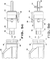
- the latch 130 of the illustrated embodiment includes a chamfered leading edge 132 ( FIG. 5D ) that when moved in the direction of an arrow 112 will contact a distal edge 107 of the drive unit 101.
- the incline of the chamfered leading edge 132 contacting the distal edge 107 causes the latch 130 to pivot about hinge 189, similar to the pivot illustrated in FIG. 5B .
- the example latch 130 includes a living hinge that enables pivoting about the rotational axis 187.
- hinge action may be achieved with a pin and spring combination or any other effective mechanism or structure.
- the latch 130 When the latch 130 is moved in the direction of the arrow 112 into one of the latch receiving locations in the form of annular groove 105 of the drive unit 101, the latch 130 may be described as "snapping" into place in the groove 105.
- the latch 130 includes an engaging member 133 ( FIG. 5D ) that, when the hub 110 is seated in the drive unit 101, is movable from the second position ( FIG. 5B ) that does not secure the hub 110 relative to the drive unit 101 to the first position ( FIG.
- the engaging member 133 effectively forms a hook, but in other embodiments, engaging members may include any effective securing structure, including but limited to a pin, a wedge, a key, or a thread.
- the latch 130 extends partially around an exterior portion of the drive unit 101, 201, 301 when the hub 110, 210, 310 is telescoped within the drive unit 101, 201, 301. With the latch 130 in the first position, the hub 110, 210, 310 may be described as being longitudinally and radially locked at two, three, and six discrete radial orientations respectively relative to the drive unit 101, 201, 301.
- the example drive unit 101 of the cutting tool 100 includes two slots 109 ( FIGS. 2 , 3 , and 5A-5D ) open on the distal end of the drive unit 101.
- the example hub 110 includes two protrusions 119 ( FIGS. 2 , 4 , and 5A-5D ).
- the protrusions 119 extend radially outward from the outer surface 191 of the hub 110 and are configured to be rotationally aligned (relative to the longitudinal axis 102) with and telescoped in the slots 109 of the drive unit 101. As shown in FIGS. 5A and 5B , the protrusions 119 may be telescoped or seated in the slots 109 in the drive unit 101 to orient the hub 110 of the cutting implement 150 relative to the drive unit 101.
- the example two protrusions 119 are configured to be aligned, telescoped, and seated in the two slots 109 in the drive unit 101 in two different orientations that orient the hub 110 of the cutting implement 150 in two different orientations relative to the drive unit 101. Consequently, the hub 110 may be positioned at two discrete radial orientations relative to the drive unit 101 when the hub 110 is fully seated in the drive unit 101. As depicted by an arrow 113 in FIG. 5D , the relative orientation of the hub 110 and the cutting implement 150 has been changed by one-half of a rotation from the orientation of FIGS. 5A-5C so that a second orientation may be achieved without substituting the instruments being used.
- a drive unit 201 of the cutting tool 200 includes three slots 209 open on the distal end of the drive unit 101 ( FIGS. 6 and 7 ; two of three slots 209 are visible in FIG. 6 ).
- Example hub 210 includes three protrusions 219 extending radially outward from the outer surface of the hub 210 ( FIGS. 6 and 8 ; two of three protrusions 219 are visible) configured to be rotationally aligned (relative to the longitudinal axis 102) with and telescoped in the three slots 209 of the drive unit 201.
- the cutting tool 200 also includes an implementation of the latch 130 fixed to the outside surface of the hub 210.
- the protrusions 219 may be seated in the three slots 209 in the drive unit 201 to orient the hub 210 of the cutting implement 150 relative to the drive unit 201.
- the three protrusions 219 are configured to be aligned, telescoped, and seated in the three slots 209 in the drive unit 201 in three different orientations that orient the hub 210 of the cutting implement 150 in three different orientations relative to the drive unit 201. Consequently, the hub 210 may be positioned at three discrete radial orientations relative to the drive unit 201 when the hub 210 is fully seated in the drive unit 201.
- the relative orientation of the hub 210 of the cutting implement 150 may be changed by one-third of a rotation without substituting the instruments being used.
- a drive unit may include any number of slots or other mating features to provide for alternative orientations of a cutting implement with a drive unit. Some embodiments may include a lesser but complimentary number of protrusions than slots.
- either of the drive units 101, 201 may be coupled with a hub that has only one protrusion and a desired alignment may be achieved when the hub is seated in the drive unit 101, 201.
- the drive unit 201 may be coupled with a hub that has two protrusions approximately 120 degrees apart and a desired alignment may be achieved when the hub is seated in the drive unit 201.
- Releasable coupling between the drive unit 201 and the hub 210 with the latch 130 is essentially similar to the releasable coupling described in connection with the drive unit 101 and hub 110 and will not be additionally described here so as not to unduly complicate the disclosure.
- a cutting tool 300 is illustrated in FIGS. 9 and 10 with a drive unit 301 that includes an angularly sided opening 308 near a distal end of the drive unit 301.
- the angularly sided opening 308 has six sides of equal length. However, in other embodiments, the number of sides may be larger or smaller than six and the lengths of each side may or may not be equal.
- the cutting tool 300 depicted also includes a hub 310, an implementation of the latch 130 fixed to the hub 310 of the cutting implement 150 coupled with the hub 310.
- the hub 310 shown in FIGS. 9 and 10 includes an angularly sided proximal connector 318 configured to be aligned and seated in the angularly sided opening 308.
- the angularly sided proximal connector 318 shown has six sides of equal length, but other embodiments may have a larger or smaller number of sides and each side may or may not be of equal length.
- an angularly sided proximal connector of some embodiments may include four sides. Such a four-sided connector may fit within a four-sided opening, may fit within a six-sided opening such as the angularly sided opening 308, or may fit within any opening with which the connector cooperates.
- the angularly sided proximal connector 318 may be seated in the angularly sided opening 308 to orient the hub 310 of the cutting implement 150 relative to the drive unit 301.
- the angularly sided proximal connector 318 and the angularly sided opening 308 are configured to be aligned and seated together in six different orientations that orient the hub 310 of the cutting implement 150 in six different orientations relative to the drive unit 301. Consequently, the hub 310 may be positioned at six discrete radial orientations relative to the drive unit 301 when the hub 310 is fully seated in the drive unit 301.
- other cooperating shapes of proximal connectors and openings may be used to provide different numbers and increments of relative orientations.
- the drive unit 301 depicted in FIG. 9 includes a longitudinal axis 302 and a perimeter, where the perimeter extends about a cross-section of the drive unit 301 transverse to the longitudinal axis 302 at the distal end of the drive unit 301.
- a cross-section of the perimeter along some portions of the drive unit 301 is substantially circular, but at other portions is irregularly shaped. No specific perimeter cross-sectional shape is required to be within the scope of the various embodiments.
- the latch receiving locations in the form of annular groove 305 of the illustrated embodiment are formed by a flange or rim 304 in combination with a generally circular cross-section of the drive unit 301.
- the resulting structure provides substantially continuous latch receiving locations about the perimeter of the drive unit 301.
- the hub 310 of the illustrated embodiment is configured to releasably couple with the drive unit 301 at the orientations noted above for the angularly sided proximal connector 318 and the angularly sided opening 308.
- the latch 130 depicted in FIGS. 9 and 10 is configured to releasably couple between the hub 310 and at least one of the multiple latch receiving locations of the drive unit 301.
- the latch 130 is fixed to the hub 310 and configured to releasably couple with the drive unit 301.
- a latch may be fixed to a drive unit and configured to releasably couple with a hub.
- any effective mechanism or structure capable of restricting longitudinal separation of a hub and the drive unit when in a first position and permitting longitudinal separation of a hub and a drive unit in a second position may be a "latch" as that term is used herein.
- the latch 130 is positioned on the hub 310 such that when the hub 310 is moved proximally along the longitudinal axis 302 of the drive unit 301 to couple with the drive unit 301, the latch 130 is forced into a position that secures the hub 310 relative to the drive unit 301 on at least one of the latch receiving locations of the drive unit 301.
- the latch 130 of the illustrated embodiment includes the same structure as described in association with FIGS. 1-5D herein and will not be additionally described here so as not to unduly complicate the disclosure.
- the cutting implement 150 as shown includes the hub 110, 210, 310.
- the cutting implement 150 shown in FIG. 4 includes an outer tube or outer tubular member 151 and an inner tubular member 152 that has a cutter 153 near a distal tip of the cutting implement 150.
- the example cutter 153 is part of the inner tubular member 152 and is configured to rotate relative to the outer tubular member 151.
- the outer tubular member 151 shown is rotationally fixed relative to the hub 110, 210, 310.
- the outer tubular member 151 includes an opening 155 in a radial segment near the distal tip of the outer tubular member 151 through which the cutter 153 is configured to cut.
- the opening 155 and such openings of other embodiments are not required to have any specific shape but may be any effective shape through which cutting may be accomplished.
- the inner tube or inner tubular member 152 is sized to fit within the outer tubular member 151 and be rotated relative to the outer tubular member 151. Because the outer tubular member 151 is rotationally fixed relative to the hub 110, 210, 310, changing orientation of the hub 110, 210, 310 relative to the drive unit 101, 201, 301 causes the opening 155 to be oriented at a changed orientation with the drive unit 101, 201, 301.
- the inner tubular member 152 includes a drive tang or torque transfer element 156 ( FIGS.
- the torque transfer element 156 extends from a proximal end of the inner tubular member 152 to enable the inner tubular member 152 to be turned by the drive unit 101, 201, 301 when the hub 110, 210, 310 is seated in the drive unit 101, 201, 301, as shown in FIGS. 1 , 5A , 6 , and 11 . Any effective mechanism for transferring torque from a drive unit to an inner tubular member may be used in other embodiments.
- the tubular configuration of the inner tubular member 152 may be useful in removing material cut or otherwise manipulated by a cutting tool by applying a negative pressure to the pathway within the inner tubular member 152.
- other embodiments may include an inner member that is not open along all or even part of its length.
- the cutter 153 may include a sharpened edge that slices tissue directly and may include an edge that works in combination with an inner edge of the opening 155 to shear tissue between the inner tubular member 152 and the outer tubular member 151.
- a sharpened edge of some embodiments may be the same edge that shears tissue in combination with an outer component.
- the cutter 153 shown is integral with the distal end of the inner tubular member 152.
- a cutter may be a module or component configured to couple at a distal end of the inner member by any effective mechanism.
- Cutting elements may be formed from the same material as an inner member or a different material.
- Cutting elements of various embodiments may include blades, burrs, rasps, abrasives, or any other devices effective to cut, abrade, scratch, rub, dislodge, or otherwise manipulate tissue.
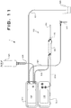
- Still another embodiment is a system for cutting 1 as illustrated in FIG. 11 .
- the system for cutting 1 shown includes a cutting tool 100, a resection control 510, and a fluid management system.
- the cutting tool 100 is shown in FIG. 11 , but either of the cutting tools 200, 300 or other alternative cutting tools may be employed as part of the system for cutting 1.
- Depicted cutting tool 100 of the system for cutting 1 include the drive unit 101 with a longitudinal axis and a perimeter about a cross-section of the drive unit 101 transverse to the longitudinal axis, wherein there are multiple latch receiving locations in the form of an annular groove about the perimeter, a cutting implement 150 with a hub 110 configured to releasably couple with the drive unit 101, a latch configured to releasably couple between the hub 110 and at least one of the multiple latch receiving locations, and a cutter near a distal tip of the cutting implement 150.
- the illustrated system for cutting 1 includes the resection control 510 that is electrically coupled with the drive unit 101 by a cable 511.
- the resection control 510 may be used to one or more of provide power to the drive unit 101, receive operator inputs from the drive unit 101, sense operating parameters of the drive unit 101, receive operator inputs from external switches or controls such as foot operated switches or controls, provide, set, or display alerts to a user based on operations of the cutting tool 100, and send and receive signals to and from a pump control 520.
- the resection control 510 illustrated also includes a resection display panel 518, which may be used to communicate information to a user and may be used to input settings or other information into the resection control 510 or other connected components of the control system. Other knobs, switches, controls, and the like may be used to control, set, or calibrate the resection control 510 as well.
- the pump control 520 is part of a fluid management system used in conjunction with fluid supply, tubing, and disposal components as described herein to facilitate the use of the cutting tool 100.
- fluids such as saline may be used during endoscopic surgical procedures to provide a clear operating medium in which to perform endoscopic surgical tasks.
- the pump control 520 may be used to one or more of provide fluid to the drive unit 101, sense operating parameters of the drive unit 101, manage waste fluid, receive operator inputs from external switches or controls such as foot operated switches or controls, and send and receive signals to and from the resection control 510.
- a fluid inflow line 521 is shown coupled between the pump control 520 and a patient joint cannula 522.
- the patient joint cannula 522 may provide one or both a passageway through which the cutting tool 100 may be introduced into a joint and an entry port for fluid supplied though the fluid inflow line 521.
- one or more additional fluid lines may be used to supply fluid or remove fluid from a surgical site from locations different than those illustrated.
- a saline bag 523 is shown providing a fresh fluid supply to the pump control 520 through a supply line 524 in the present embodiment. Any other effective fluid source may be used in various embodiments.
- a suction line 525 is shown coupled between the cutting tool 100 and the pump control 520, which when activated draws waste fluid through the cutting tool 100 and into the pump control 520 where the fluid may be diverted for waste removal.
- a waste line 527 is shown coupled between the pump control 520 and a waste receptacle 529. Any other effective supply or waste handling mechanisms may be used in other embodiments.
- the pump control 520 illustrated also includes a pump control display panel 528, which may be used to communicate information to a user and may be used to input settings or other information into the pump control 520 or other connected components of the control system. Other knobs, switches, controls, and the like may be used to control, set, or calibrate the pump control 520 as well.
- biocompatible materials may include in whole or in part: non-reinforced polymers, reinforced polymers, metals, ceramics, adhesives, reinforced adhesives, and combinations of these materials. Reinforcing of polymers may be accomplished with carbon, metal, or glass or any other effective material.
- biocompatible polymer materials include polyamide base resins, polyethylene, Ultra High Molecular Weight (UHMW) polyethylene, low density polyethylene, polymethylmethacrylate (PMMA), polyetheretherketone (PEEK), polyetherketoneketone (PEKK), a polymeric hydroxyethylmethacrylate (PHEMA), and polyurethane, any of which may be reinforced.
- Polymers used as bearing surfaces in particular may in whole or in part include one or more of cross-linked and highly cross-linked polyethylene.
- Example biocompatible metals include stainless steel and other steel alloys, cobalt chrome alloys, zirconium, oxidized zirconium, tantalum, titanium, titanium alloys, titanium-nickel alloys such as Nitinol and other superelastic or shape-memory metal alloys.
- proximal, distal, near, around, and the like have been used relatively herein. However, such terms are not limited to specific coordinate orientations, distances, or sizes, but are used to describe relative positions referencing particular embodiments. Such terms are not generally limiting to the scope of the claims made herein.
Landscapes
- Health & Medical Sciences (AREA)
- Surgery (AREA)
- Life Sciences & Earth Sciences (AREA)
- Biomedical Technology (AREA)
- Nuclear Medicine, Radiotherapy & Molecular Imaging (AREA)
- Engineering & Computer Science (AREA)
- Orthopedic Medicine & Surgery (AREA)
- Heart & Thoracic Surgery (AREA)
- Medical Informatics (AREA)
- Molecular Biology (AREA)
- Animal Behavior & Ethology (AREA)
- General Health & Medical Sciences (AREA)
- Public Health (AREA)
- Veterinary Medicine (AREA)
- Surgical Instruments (AREA)
Claims (10)
- Outil de coupe (150) destiné à être utilisé avec une unité d'entraînement (101), l'outil de coupe comprenant :un moyeu (110) qui définit une surface extérieure (191), la surface extérieure (191) étant configurée pour venir en butée contre une surface intérieure (193) de l'unité d'entraînement (101) ;un tube externe (151) accouplé rigide au moyeu, le tube externe (151) définissant un axe longitudinal (102) ;un tube interne (152) emboîté dans le tube externe (151) le long de l'axe longitudinal (102) ;une première protubérance (119) qui s'étend radialement vers l'extérieur depuis la surface extérieure du moyen (110) et qui est configurée pour s'aligner avec une fente (109) correspondante et s'emboîter dans celle-ci dans l'unité d'entraînement (101) ;un verrou (130) disposé sur la surface extérieure (191) du moyeu, le verrou (130) comprenant un élément d'engagement (133) sur une surface intérieure du verrou (130) configuré pour s'engager dans une rainure annulaire (105) correspondante sur une surface externe de l'unité d'entraînement (101), le verrou (130) comprenant une charnière qui définit un axe de rotation, et l'axe de rotation, projeté sur l'axe longitudinal (102), étant perpendiculaire à l'axe longitudinal (102) ; etune lame de coupe (153) définie au niveau de l'extrémité distale du tube externe (151) et du tube interne (152).
- Outil de coupe (150) selon la revendication 1, dans lequel le moyeu (110) comprend en outre une deuxième protubérance (119) opposée à la première protubérance (119) sur la surface extérieure (191) du moyeu (110).
- Élément de coupe (150) selon la revendication 1, dans lequel le moyeu (110) comprend en outre une deuxième protubérance (119) qui s'étend radialement vers l'extérieur depuis le moyeu (110) et une troisième protubérance (119) qui s'étend radialement vers l'extérieur depuis le moyeu (110), les première, deuxième et troisième protubérances (119) étant disposées à des positions circonférentielles équidistantes autour de la circonférence du moyeu (110).
- Outil de coupe (150) selon la revendication 2 ou 3, dans lequel le verrou (130) se trouve entre deux protubérances (119) le long de la circonférence de la surface extérieure (191) du moyeu (110).
- Outil de coupe (150) selon l'une quelconque des revendications 1 à 4, dans lequel le verrou (130) comprend en outre :un bord chanfreiné (132) sur une extrémité proximale du verrou (130), le bord chanfreiné (132) étant en relation fonctionnelle avec l'élément d'engagement (133) ; etle bord chanfreiné (132) et l'élément
d'engagement (133) étant configurés de sorte que, quand le moyeu (110) est déplacé de façon proximale le long d'un axe longitudinal, le verrou soit forcé dans une position dans laquelle l'élément d'engagement s'accouple à la rainure annulaire (105) de l'unité d'entraînement (101). - Outil de coupe (150) selon l'une quelconque des revendications 1 à 5, dans lequel un axe de rotation du verrou (130) est au moins un axe sélectionné dans le groupe consistant en : une tangente à la surface externe du moyeu (110) ; et une parallèle à une tangente à la surface externe du moyeu (110).
- Système comprenant :l'outil de coupe (150) selon l'une quelconque des revendications 1 à 6 ; etune unité d'entraînement (101) comprenant :un axe longitudinal (102) ;un périmètre autour d'une section transversale de l'unité d'entraînement (101), transversale à l'axe longitudinal (102), le périmètre étant au niveau d'une extrémité distale de l'unité d'entraînement (101) ;une rainure annulaire (105) disposée de façon proximale par rapport au périmètre sur une surface extérieure de l'unité d'entraînement (101) ; etune ouverture (199) au niveau de l'extrémité distale de l'unité d'entraînement (101),
l'ouverture (199) définissant un volume interne avec une surface intérieure (193). - Système selon la revendication 7, comprenant en outre :l'unité d'entraînement (101) qui comprend deux fentes (109) ou plus ouvertes sur l'extrémité distale du périmètre ;le moyeu (110) qui comprend deux protubérances (119) ou plus qui s'étendent radialement vers l'extérieur depuis le moyeu (110), chaque protubérance (119) étant emboîtée dans une fente (109) de l'unité d'entraînement (101).
- Système selon la revendication 7 ou 8, comprenant en outre :l'unité d'entraînement (101) qui comprend trois encoches (109) ouvertes sur l'extrémité distale du périmètre ;le moyeu (110) qui comprend trois protubérances (119) qui s'étendent radialement vers l'extérieur depuis le moyeu, chaque protubérance (119) étant emboîtée dans une fente (109) de l'unité d'entraînement (101).
- Système selon l'une quelconque des revendications 7 à 9, dans lequel le périmètre est circulaire au niveau de la section transversale.
Applications Claiming Priority (2)
| Application Number | Priority Date | Filing Date | Title |
|---|---|---|---|
| US201662322464P | 2016-04-14 | 2016-04-14 | |
| PCT/US2017/027006 WO2017180622A1 (fr) | 2016-04-14 | 2017-04-11 | Pièce à main chirurgicale et système de moyeu de verrouillage |
Publications (2)
| Publication Number | Publication Date |
|---|---|
| EP3442445A1 EP3442445A1 (fr) | 2019-02-20 |
| EP3442445B1 true EP3442445B1 (fr) | 2021-06-16 |
Family
ID=58645403
Family Applications (1)
| Application Number | Title | Priority Date | Filing Date |
|---|---|---|---|
| EP17720643.0A Active EP3442445B1 (fr) | 2016-04-14 | 2017-04-11 | Pièce à main chirurgicale et système de moyeu de verrouillage |
Country Status (4)
| Country | Link |
|---|---|
| US (1) | US10864010B2 (fr) |
| EP (1) | EP3442445B1 (fr) |
| CN (1) | CN109104857A (fr) |
| WO (1) | WO2017180622A1 (fr) |
Families Citing this family (2)
| Publication number | Priority date | Publication date | Assignee | Title |
|---|---|---|---|---|
| US11033315B2 (en) * | 2017-12-15 | 2021-06-15 | DePuy Synthes Products, Inc. | Orthopedic adapter for an electric impacting tool |
| US11937842B2 (en) * | 2019-10-04 | 2024-03-26 | Gyrus Acmi, Inc. | Detachable handheld tissue removal device |
Family Cites Families (14)
| Publication number | Priority date | Publication date | Assignee | Title |
|---|---|---|---|---|
| US5376078B1 (en) | 1992-12-10 | 1997-06-24 | Linvatec Corp | Rotatable surgical cutting instrument with positionally adjustable window |
| CA2256132A1 (fr) | 1998-12-16 | 2000-06-16 | Brian M. Strauss | Mecanisme d'accessoire rotatif pour relier un sous-ensemble dispositif de traitement des obstructions medicales a un moteur d'entrainement |
| US7066940B2 (en) | 2001-03-21 | 2006-06-27 | Medtronic, Inc. | Surgical instrument with rotary cutting member and quick release coupling arrangement |
| US7226460B2 (en) * | 2004-08-02 | 2007-06-05 | Karl Storz Endovision, Inc. | Surgical instrument attachment system |
| US10080578B2 (en) * | 2008-12-16 | 2018-09-25 | Nico Corporation | Tissue removal device with adjustable delivery sleeve for neurosurgical and spinal surgery applications |
| US8801713B2 (en) | 2011-04-07 | 2014-08-12 | DePuy Synthes Products, LLC | Surgical drill instrument with motor and locking mechanism to receive an attachment and a cutting burr |
| AU2012364646B2 (en) * | 2012-01-06 | 2016-12-15 | Jai Singh | An insert and insert system for a laparoscopic instrument |
| US10327795B2 (en) * | 2013-05-17 | 2019-06-25 | Trokamed Gmbh | Connection for a morcellator |
| US9797486B2 (en) | 2013-06-20 | 2017-10-24 | Covidien Lp | Adapter direct drive with manual retraction, lockout and connection mechanisms |
| KR20160085774A (ko) | 2013-11-14 | 2016-07-18 | 스미스 앤드 네퓨, 인크. | 제거 가능한 부착 조립체를 가진 수공구 |
| US10245063B2 (en) | 2014-01-27 | 2019-04-02 | Smith & Nephew, Inc. | Surgical drive apparatus |
| US9480484B2 (en) | 2014-08-01 | 2016-11-01 | Smith & Nephew, Inc. | Modular surgical drive hub |
| WO2016022790A1 (fr) * | 2014-08-08 | 2016-02-11 | Smith & Nephew, Inc. | Dispositif de résection de détection de charge |
| DE102014115873A1 (de) | 2014-10-31 | 2016-05-04 | Karl Storz Gmbh & Co. Kg | Zerlegbares medizinisches Instrument |
-
2017
- 2017-04-11 EP EP17720643.0A patent/EP3442445B1/fr active Active
- 2017-04-11 CN CN201780022499.8A patent/CN109104857A/zh active Pending
- 2017-04-11 WO PCT/US2017/027006 patent/WO2017180622A1/fr active Application Filing
- 2017-04-11 US US16/086,677 patent/US10864010B2/en active Active
Non-Patent Citations (1)
| Title |
|---|
| None * |
Also Published As
| Publication number | Publication date |
|---|---|
| CN109104857A (zh) | 2018-12-28 |
| WO2017180622A1 (fr) | 2017-10-19 |
| US10864010B2 (en) | 2020-12-15 |
| EP3442445A1 (fr) | 2019-02-20 |
| US20190110807A1 (en) | 2019-04-18 |
Similar Documents
| Publication | Publication Date | Title |
|---|---|---|
| JP5833733B2 (ja) | 手術器具のためのブレード保持機構 | |
| AU674993B2 (en) | Surgical device | |
| EP2564795B1 (fr) | Appareils d'excision de tissus | |
| AU2015315576B2 (en) | Method for resection of tumors and tissues | |
| EP3689278B1 (fr) | Réducteur tumoral | |
| JP6726209B2 (ja) | 外科用切断器具 | |
| EP2849658B1 (fr) | Ensemble de lame jetable et ensemble moyeu de lame réutilisable | |
| EP3524188B1 (fr) | Dispositif électrique de résection de tissus | |
| EP3442445B1 (fr) | Pièce à main chirurgicale et système de moyeu de verrouillage | |
| EP3142576A1 (fr) | Appareil et procédé de coupe de tissu | |
| EP3190993B1 (fr) | Dispositif de marge tumorale | |
| WO2017180423A1 (fr) | Instrument de coupe à palier | |
| US20220079665A1 (en) | Tissue resecting device including a blade lock and release mechanism | |
| US11937842B2 (en) | Detachable handheld tissue removal device | |
| US20210145471A1 (en) | Mechanical resection blade | |
| US11812989B2 (en) | Medical device |
Legal Events
| Date | Code | Title | Description |
|---|---|---|---|
| STAA | Information on the status of an ep patent application or granted ep patent |
Free format text: STATUS: UNKNOWN |
|
| STAA | Information on the status of an ep patent application or granted ep patent |
Free format text: STATUS: THE INTERNATIONAL PUBLICATION HAS BEEN MADE |
|
| PUAI | Public reference made under article 153(3) epc to a published international application that has entered the european phase |
Free format text: ORIGINAL CODE: 0009012 |
|
| STAA | Information on the status of an ep patent application or granted ep patent |
Free format text: STATUS: REQUEST FOR EXAMINATION WAS MADE |
|
| 17P | Request for examination filed |
Effective date: 20181114 |
|
| AK | Designated contracting states |
Kind code of ref document: A1 Designated state(s): AL AT BE BG CH CY CZ DE DK EE ES FI FR GB GR HR HU IE IS IT LI LT LU LV MC MK MT NL NO PL PT RO RS SE SI SK SM TR |
|
| AX | Request for extension of the european patent |
Extension state: BA ME |
|
| DAV | Request for validation of the european patent (deleted) | ||
| DAX | Request for extension of the european patent (deleted) | ||
| STAA | Information on the status of an ep patent application or granted ep patent |
Free format text: STATUS: EXAMINATION IS IN PROGRESS |
|
| 17Q | First examination report despatched |
Effective date: 20190830 |
|
| GRAP | Despatch of communication of intention to grant a patent |
Free format text: ORIGINAL CODE: EPIDOSNIGR1 |
|
| STAA | Information on the status of an ep patent application or granted ep patent |
Free format text: STATUS: GRANT OF PATENT IS INTENDED |
|
| INTG | Intention to grant announced |
Effective date: 20201111 |
|
| GRAS | Grant fee paid |
Free format text: ORIGINAL CODE: EPIDOSNIGR3 |
|
| GRAA | (expected) grant |
Free format text: ORIGINAL CODE: 0009210 |
|
| STAA | Information on the status of an ep patent application or granted ep patent |
Free format text: STATUS: THE PATENT HAS BEEN GRANTED |
|
| AK | Designated contracting states |
Kind code of ref document: B1 Designated state(s): AL AT BE BG CH CY CZ DE DK EE ES FI FR GB GR HR HU IE IS IT LI LT LU LV MC MK MT NL NO PL PT RO RS SE SI SK SM TR |
|
| REG | Reference to a national code |
Ref country code: GB Ref legal event code: FG4D |
|
| REG | Reference to a national code |
Ref country code: CH Ref legal event code: EP |
|
| REG | Reference to a national code |
Ref country code: DE Ref legal event code: R096 Ref document number: 602017040351 Country of ref document: DE |
|
| REG | Reference to a national code |
Ref country code: AT Ref legal event code: REF Ref document number: 1401662 Country of ref document: AT Kind code of ref document: T Effective date: 20210715 |
|
| REG | Reference to a national code |
Ref country code: IE Ref legal event code: FG4D |
|
| REG | Reference to a national code |
Ref country code: LT Ref legal event code: MG9D |
|
| PG25 | Lapsed in a contracting state [announced via postgrant information from national office to epo] |
Ref country code: FI Free format text: LAPSE BECAUSE OF FAILURE TO SUBMIT A TRANSLATION OF THE DESCRIPTION OR TO PAY THE FEE WITHIN THE PRESCRIBED TIME-LIMIT Effective date: 20210616 Ref country code: LT Free format text: LAPSE BECAUSE OF FAILURE TO SUBMIT A TRANSLATION OF THE DESCRIPTION OR TO PAY THE FEE WITHIN THE PRESCRIBED TIME-LIMIT Effective date: 20210616 Ref country code: HR Free format text: LAPSE BECAUSE OF FAILURE TO SUBMIT A TRANSLATION OF THE DESCRIPTION OR TO PAY THE FEE WITHIN THE PRESCRIBED TIME-LIMIT Effective date: 20210616 Ref country code: BG Free format text: LAPSE BECAUSE OF FAILURE TO SUBMIT A TRANSLATION OF THE DESCRIPTION OR TO PAY THE FEE WITHIN THE PRESCRIBED TIME-LIMIT Effective date: 20210916 |
|
| REG | Reference to a national code |
Ref country code: AT Ref legal event code: MK05 Ref document number: 1401662 Country of ref document: AT Kind code of ref document: T Effective date: 20210616 |
|
| REG | Reference to a national code |
Ref country code: NL Ref legal event code: MP Effective date: 20210616 |
|
| PG25 | Lapsed in a contracting state [announced via postgrant information from national office to epo] |
Ref country code: NO Free format text: LAPSE BECAUSE OF FAILURE TO SUBMIT A TRANSLATION OF THE DESCRIPTION OR TO PAY THE FEE WITHIN THE PRESCRIBED TIME-LIMIT Effective date: 20210916 Ref country code: SE Free format text: LAPSE BECAUSE OF FAILURE TO SUBMIT A TRANSLATION OF THE DESCRIPTION OR TO PAY THE FEE WITHIN THE PRESCRIBED TIME-LIMIT Effective date: 20210616 Ref country code: RS Free format text: LAPSE BECAUSE OF FAILURE TO SUBMIT A TRANSLATION OF THE DESCRIPTION OR TO PAY THE FEE WITHIN THE PRESCRIBED TIME-LIMIT Effective date: 20210616 Ref country code: GR Free format text: LAPSE BECAUSE OF FAILURE TO SUBMIT A TRANSLATION OF THE DESCRIPTION OR TO PAY THE FEE WITHIN THE PRESCRIBED TIME-LIMIT Effective date: 20210917 Ref country code: LV Free format text: LAPSE BECAUSE OF FAILURE TO SUBMIT A TRANSLATION OF THE DESCRIPTION OR TO PAY THE FEE WITHIN THE PRESCRIBED TIME-LIMIT Effective date: 20210616 |
|
| PG25 | Lapsed in a contracting state [announced via postgrant information from national office to epo] |
Ref country code: EE Free format text: LAPSE BECAUSE OF FAILURE TO SUBMIT A TRANSLATION OF THE DESCRIPTION OR TO PAY THE FEE WITHIN THE PRESCRIBED TIME-LIMIT Effective date: 20210616 Ref country code: CZ Free format text: LAPSE BECAUSE OF FAILURE TO SUBMIT A TRANSLATION OF THE DESCRIPTION OR TO PAY THE FEE WITHIN THE PRESCRIBED TIME-LIMIT Effective date: 20210616 Ref country code: AT Free format text: LAPSE BECAUSE OF FAILURE TO SUBMIT A TRANSLATION OF THE DESCRIPTION OR TO PAY THE FEE WITHIN THE PRESCRIBED TIME-LIMIT Effective date: 20210616 Ref country code: ES Free format text: LAPSE BECAUSE OF FAILURE TO SUBMIT A TRANSLATION OF THE DESCRIPTION OR TO PAY THE FEE WITHIN THE PRESCRIBED TIME-LIMIT Effective date: 20210616 Ref country code: RO Free format text: LAPSE BECAUSE OF FAILURE TO SUBMIT A TRANSLATION OF THE DESCRIPTION OR TO PAY THE FEE WITHIN THE PRESCRIBED TIME-LIMIT Effective date: 20210616 Ref country code: PT Free format text: LAPSE BECAUSE OF FAILURE TO SUBMIT A TRANSLATION OF THE DESCRIPTION OR TO PAY THE FEE WITHIN THE PRESCRIBED TIME-LIMIT Effective date: 20211018 Ref country code: NL Free format text: LAPSE BECAUSE OF FAILURE TO SUBMIT A TRANSLATION OF THE DESCRIPTION OR TO PAY THE FEE WITHIN THE PRESCRIBED TIME-LIMIT Effective date: 20210616 Ref country code: SK Free format text: LAPSE BECAUSE OF FAILURE TO SUBMIT A TRANSLATION OF THE DESCRIPTION OR TO PAY THE FEE WITHIN THE PRESCRIBED TIME-LIMIT Effective date: 20210616 Ref country code: SM Free format text: LAPSE BECAUSE OF FAILURE TO SUBMIT A TRANSLATION OF THE DESCRIPTION OR TO PAY THE FEE WITHIN THE PRESCRIBED TIME-LIMIT Effective date: 20210616 |
|
| PG25 | Lapsed in a contracting state [announced via postgrant information from national office to epo] |
Ref country code: PL Free format text: LAPSE BECAUSE OF FAILURE TO SUBMIT A TRANSLATION OF THE DESCRIPTION OR TO PAY THE FEE WITHIN THE PRESCRIBED TIME-LIMIT Effective date: 20210616 |
|
| REG | Reference to a national code |
Ref country code: DE Ref legal event code: R097 Ref document number: 602017040351 Country of ref document: DE |
|
| PLBE | No opposition filed within time limit |
Free format text: ORIGINAL CODE: 0009261 |
|
| STAA | Information on the status of an ep patent application or granted ep patent |
Free format text: STATUS: NO OPPOSITION FILED WITHIN TIME LIMIT |
|
| PG25 | Lapsed in a contracting state [announced via postgrant information from national office to epo] |
Ref country code: DK Free format text: LAPSE BECAUSE OF FAILURE TO SUBMIT A TRANSLATION OF THE DESCRIPTION OR TO PAY THE FEE WITHIN THE PRESCRIBED TIME-LIMIT Effective date: 20210616 |
|
| 26N | No opposition filed |
Effective date: 20220317 |
|
| PG25 | Lapsed in a contracting state [announced via postgrant information from national office to epo] |
Ref country code: AL Free format text: LAPSE BECAUSE OF FAILURE TO SUBMIT A TRANSLATION OF THE DESCRIPTION OR TO PAY THE FEE WITHIN THE PRESCRIBED TIME-LIMIT Effective date: 20210616 |
|
| PG25 | Lapsed in a contracting state [announced via postgrant information from national office to epo] |
Ref country code: IT Free format text: LAPSE BECAUSE OF FAILURE TO SUBMIT A TRANSLATION OF THE DESCRIPTION OR TO PAY THE FEE WITHIN THE PRESCRIBED TIME-LIMIT Effective date: 20210616 |
|
| REG | Reference to a national code |
Ref country code: CH Ref legal event code: PL |
|
| REG | Reference to a national code |
Ref country code: BE Ref legal event code: MM Effective date: 20220430 |
|
| PG25 | Lapsed in a contracting state [announced via postgrant information from national office to epo] |
Ref country code: MC Free format text: LAPSE BECAUSE OF FAILURE TO SUBMIT A TRANSLATION OF THE DESCRIPTION OR TO PAY THE FEE WITHIN THE PRESCRIBED TIME-LIMIT Effective date: 20210616 Ref country code: LU Free format text: LAPSE BECAUSE OF NON-PAYMENT OF DUE FEES Effective date: 20220411 Ref country code: FR Free format text: LAPSE BECAUSE OF NON-PAYMENT OF DUE FEES Effective date: 20220430 Ref country code: CH Free format text: LAPSE BECAUSE OF NON-PAYMENT OF DUE FEES Effective date: 20220430 Ref country code: LI Free format text: LAPSE BECAUSE OF NON-PAYMENT OF DUE FEES Effective date: 20220430 |
|
| PG25 | Lapsed in a contracting state [announced via postgrant information from national office to epo] |
Ref country code: BE Free format text: LAPSE BECAUSE OF NON-PAYMENT OF DUE FEES Effective date: 20220430 |
|
| PG25 | Lapsed in a contracting state [announced via postgrant information from national office to epo] |
Ref country code: IE Free format text: LAPSE BECAUSE OF NON-PAYMENT OF DUE FEES Effective date: 20220411 |
|
| P01 | Opt-out of the competence of the unified patent court (upc) registered |
Effective date: 20230525 |
|
| PGFP | Annual fee paid to national office [announced via postgrant information from national office to epo] |
Ref country code: DE Payment date: 20230321 Year of fee payment: 7 |
|
| PG25 | Lapsed in a contracting state [announced via postgrant information from national office to epo] |
Ref country code: HU Free format text: LAPSE BECAUSE OF FAILURE TO SUBMIT A TRANSLATION OF THE DESCRIPTION OR TO PAY THE FEE WITHIN THE PRESCRIBED TIME-LIMIT; INVALID AB INITIO Effective date: 20170411 |
|
| PG25 | Lapsed in a contracting state [announced via postgrant information from national office to epo] |
Ref country code: MK Free format text: LAPSE BECAUSE OF FAILURE TO SUBMIT A TRANSLATION OF THE DESCRIPTION OR TO PAY THE FEE WITHIN THE PRESCRIBED TIME-LIMIT Effective date: 20210616 Ref country code: CY Free format text: LAPSE BECAUSE OF FAILURE TO SUBMIT A TRANSLATION OF THE DESCRIPTION OR TO PAY THE FEE WITHIN THE PRESCRIBED TIME-LIMIT Effective date: 20210616 |
|
| PGFP | Annual fee paid to national office [announced via postgrant information from national office to epo] |
Ref country code: GB Payment date: 20240321 Year of fee payment: 8 |