EP3442219B1 - Information processing apparatus, information processing method, and storage medium - Google Patents
Information processing apparatus, information processing method, and storage medium Download PDFInfo
- Publication number
- EP3442219B1 EP3442219B1 EP18188040.2A EP18188040A EP3442219B1 EP 3442219 B1 EP3442219 B1 EP 3442219B1 EP 18188040 A EP18188040 A EP 18188040A EP 3442219 B1 EP3442219 B1 EP 3442219B1
- Authority
- EP
- European Patent Office
- Prior art keywords
- setting information
- information
- processing
- area
- camera
- Prior art date
- Legal status (The legal status is an assumption and is not a legal conclusion. Google has not performed a legal analysis and makes no representation as to the accuracy of the status listed.)
- Active
Links
Images


Classifications
-
- H—ELECTRICITY
- H04—ELECTRIC COMMUNICATION TECHNIQUE
- H04N—PICTORIAL COMMUNICATION, e.g. TELEVISION
- H04N21/00—Selective content distribution, e.g. interactive television or video on demand [VOD]
- H04N21/40—Client devices specifically adapted for the reception of or interaction with content, e.g. set-top-box [STB]; Operations thereof
- H04N21/47—End-user applications
- H04N21/472—End-user interface for requesting content, additional data or services; End-user interface for interacting with content, e.g. for content reservation or setting reminders, for requesting event notification, for manipulating displayed content
- H04N21/4728—End-user interface for requesting content, additional data or services; End-user interface for interacting with content, e.g. for content reservation or setting reminders, for requesting event notification, for manipulating displayed content for selecting a Region Of Interest [ROI], e.g. for requesting a higher resolution version of a selected region
-
- H—ELECTRICITY
- H04—ELECTRIC COMMUNICATION TECHNIQUE
- H04N—PICTORIAL COMMUNICATION, e.g. TELEVISION
- H04N23/00—Cameras or camera modules comprising electronic image sensors; Control thereof
- H04N23/60—Control of cameras or camera modules
- H04N23/63—Control of cameras or camera modules by using electronic viewfinders
- H04N23/631—Graphical user interfaces [GUI] specially adapted for controlling image capture or setting capture parameters
-
- H—ELECTRICITY
- H04—ELECTRIC COMMUNICATION TECHNIQUE
- H04N—PICTORIAL COMMUNICATION, e.g. TELEVISION
- H04N23/00—Cameras or camera modules comprising electronic image sensors; Control thereof
- H04N23/50—Constructional details
- H04N23/54—Mounting of pick-up tubes, electronic image sensors, deviation or focusing coils
-
- H—ELECTRICITY
- H04—ELECTRIC COMMUNICATION TECHNIQUE
- H04N—PICTORIAL COMMUNICATION, e.g. TELEVISION
- H04N23/00—Cameras or camera modules comprising electronic image sensors; Control thereof
- H04N23/60—Control of cameras or camera modules
- H04N23/66—Remote control of cameras or camera parts, e.g. by remote control devices
- H04N23/661—Transmitting camera control signals through networks, e.g. control via the Internet
-
- H—ELECTRICITY
- H04—ELECTRIC COMMUNICATION TECHNIQUE
- H04N—PICTORIAL COMMUNICATION, e.g. TELEVISION
- H04N21/00—Selective content distribution, e.g. interactive television or video on demand [VOD]
- H04N21/40—Client devices specifically adapted for the reception of or interaction with content, e.g. set-top-box [STB]; Operations thereof
- H04N21/43—Processing of content or additional data, e.g. demultiplexing additional data from a digital video stream; Elementary client operations, e.g. monitoring of home network or synchronising decoder's clock; Client middleware
- H04N21/431—Generation of visual interfaces for content selection or interaction; Content or additional data rendering
- H04N21/4318—Generation of visual interfaces for content selection or interaction; Content or additional data rendering by altering the content in the rendering process, e.g. blanking, blurring or masking an image region
-
- H—ELECTRICITY
- H04—ELECTRIC COMMUNICATION TECHNIQUE
- H04N—PICTORIAL COMMUNICATION, e.g. TELEVISION
- H04N23/00—Cameras or camera modules comprising electronic image sensors; Control thereof
- H04N23/50—Constructional details
- H04N23/55—Optical parts specially adapted for electronic image sensors; Mounting thereof
-
- H—ELECTRICITY
- H04—ELECTRIC COMMUNICATION TECHNIQUE
- H04N—PICTORIAL COMMUNICATION, e.g. TELEVISION
- H04N23/00—Cameras or camera modules comprising electronic image sensors; Control thereof
- H04N23/58—Means for changing the camera field of view without moving the camera body, e.g. nutating or panning of optics or image sensors
-
- H—ELECTRICITY
- H04—ELECTRIC COMMUNICATION TECHNIQUE
- H04N—PICTORIAL COMMUNICATION, e.g. TELEVISION
- H04N23/00—Cameras or camera modules comprising electronic image sensors; Control thereof
- H04N23/60—Control of cameras or camera modules
-
- H—ELECTRICITY
- H04—ELECTRIC COMMUNICATION TECHNIQUE
- H04N—PICTORIAL COMMUNICATION, e.g. TELEVISION
- H04N23/00—Cameras or camera modules comprising electronic image sensors; Control thereof
- H04N23/60—Control of cameras or camera modules
- H04N23/62—Control of parameters via user interfaces
-
- H—ELECTRICITY
- H04—ELECTRIC COMMUNICATION TECHNIQUE
- H04N—PICTORIAL COMMUNICATION, e.g. TELEVISION
- H04N23/00—Cameras or camera modules comprising electronic image sensors; Control thereof
- H04N23/60—Control of cameras or camera modules
- H04N23/63—Control of cameras or camera modules by using electronic viewfinders
- H04N23/633—Control of cameras or camera modules by using electronic viewfinders for displaying additional information relating to control or operation of the camera
- H04N23/635—Region indicators; Field of view indicators
-
- H—ELECTRICITY
- H04—ELECTRIC COMMUNICATION TECHNIQUE
- H04N—PICTORIAL COMMUNICATION, e.g. TELEVISION
- H04N23/00—Cameras or camera modules comprising electronic image sensors; Control thereof
- H04N23/60—Control of cameras or camera modules
- H04N23/66—Remote control of cameras or camera parts, e.g. by remote control devices
-
- H—ELECTRICITY
- H04—ELECTRIC COMMUNICATION TECHNIQUE
- H04N—PICTORIAL COMMUNICATION, e.g. TELEVISION
- H04N23/00—Cameras or camera modules comprising electronic image sensors; Control thereof
- H04N23/60—Control of cameras or camera modules
- H04N23/695—Control of camera direction for changing a field of view, e.g. pan, tilt or based on tracking of objects
-
- H—ELECTRICITY
- H04—ELECTRIC COMMUNICATION TECHNIQUE
- H04N—PICTORIAL COMMUNICATION, e.g. TELEVISION
- H04N23/00—Cameras or camera modules comprising electronic image sensors; Control thereof
- H04N23/80—Camera processing pipelines; Components thereof
-
- H—ELECTRICITY
- H04—ELECTRIC COMMUNICATION TECHNIQUE
- H04N—PICTORIAL COMMUNICATION, e.g. TELEVISION
- H04N5/00—Details of television systems
- H04N5/44—Receiver circuitry for the reception of television signals according to analogue transmission standards
- H04N5/445—Receiver circuitry for the reception of television signals according to analogue transmission standards for displaying additional information
- H04N5/44504—Circuit details of the additional information generator, e.g. details of the character or graphics signal generator, overlay mixing circuits
-
- H—ELECTRICITY
- H04—ELECTRIC COMMUNICATION TECHNIQUE
- H04N—PICTORIAL COMMUNICATION, e.g. TELEVISION
- H04N7/00—Television systems
- H04N7/18—Closed-circuit television [CCTV] systems, i.e. systems in which the video signal is not broadcast
- H04N7/181—Closed-circuit television [CCTV] systems, i.e. systems in which the video signal is not broadcast for receiving images from a plurality of remote sources
Definitions
- the present invention relates to an information processing apparatus, an information processing method, and a storage medium.
- the specified areas may be overlapped with each other in some cases. In this case, there is a fear that a result desired by the user is not obtained in the network camera functions.
- Japanese Patent Laid-Open No. 2016-123004 describes a method of detecting an overlap of imaging areas of the cameras and displaying an overlap amount of the mutual imaging areas on a screen.
- Japanese Patent No. 5555044 describes a method of issuing a warning to a user that a video at the time of event occurrence is hidden by a privacy mask when areas respectively specified by a privacy mask function and an event detection function of a network camera are overlapped with each other.
- an embodiment of the present invention aims at appropriately creating setting information including the area specification and suppressing the number of occasions where an undesired image analysis result is obtained.
- the present invention in its first aspect provides an information processing apparatus as specified in claims 1 to 11.
- the present invention in its second aspect provides an information processing method as specified in claim 12.
- the present invention in its third aspect provides a storage medium as specified in claim 13.
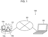
- Fig. 1 illustrates a network configuration example of an imaging system 1000 according to the present embodiment.
- the imaging system 1000 is provided with a network camera (hereinafter, which will be simply referred to as a "camera") 100 and a client apparatus 200.
- the camera 100 and the client apparatus 200 are connected to each other by a network 300 so as to be communicable with each other.
- the network 300 is constituted, for example, by a plurality of routers, switches, cables, and the like in conformity to Ethernet (registered trademark) communication specifications. It should be noted that, as long as the communication between the camera 100 and the client apparatus 200 can be performed by a configuration, any communication specifications, scales, and configurations of the network 300 may be adopted.
- the network 300 may be realized by the internet, a wired local area network (LAN), a wireless LAN, a wide area network (WAN), or any combinations of those.
- LAN local area network
- WAN wide area network
- the camera 100 is an imaging apparatus configured to image an imaging area.
- the camera 100 includes a pan driving mechanism 100a, a tilt driving mechanism 100b, and a zoom driving mechanism 100c and functions as a pan tilt zoom (PTZ) camera constituted so as to be able to change the imaging area.
- the pan driving mechanism 100a can change the imaging area of the camera 100 in a pan direction and endlessly rotate the camera 100 by 360°, for example.
- the tilt driving mechanism 100b can change the imaging area of the camera 100 in a tilt direction and rotate the camera 100 from 0° in a horizontal direction to +180° in an upper direction, for example.
- the zoom driving mechanism 100c can change the imaging area of the camera 100 in a zoom direction and arbitrary change the viewing angle of the camera 100.
- the camera 100 is not limited to the PTZ camera.
- the camera 100 may be compatible to Power over Ethernet (PoE) and also have a configuration in which power is supplied via a LAN cable.
- PoE Power over Ethernet
- the single camera 100 is connected to the network 300, but a plurality of cameras can also be connected to the network 300.
- the client apparatus 200 is constituted by a personal computer (PC) or a terminal apparatus such as a smart phone or a tablet-type PC and can transmit various commands to the camera 100.
- the commands transmitted to the camera 100 include a command for changing an imaging direction (bearing or orientation) of the camera 100 and a viewing angle, a command for changing an imaging parameter, a command related to image processing, a command for starting transmission of an image, and the like.
- the client apparatus 200 also receives a response with respect to a command from the camera 100.
- the camera 100 changes the imaging direction and the viewing angle in accordance with the command for changing the imaging direction and the viewing angle received from the client apparatus 200.
- the camera 100 also transmits the image to the client apparatus 200 in accordance with the command for starting the transmission of the image.
- the client apparatus 200 performs display control for receiving the image transmitted from the camera 100 and presenting the received image to a user who uses the client apparatus 200.
- Fig. 2 is a block diagram illustrating configuration examples of the camera 100 and the client apparatus 200.
- the camera 100 is provided with an imaging unit 101, an image processing unit 102, a system control unit 103, a lens driving unit 104, a lens control unit 105, a pan driving unit 106, a tilt driving unit 107, a pan/tilt control unit 108, and a communication unit 109.
- the camera 100 is provided with a recording unit 110 and an external input unit 111.
- the client apparatus 200 is provided with a display unit 201, an input unit 202, a system control unit 203, and a communication unit 204.
- the communication unit 109 of the camera 100 and the communication unit 204 of the client apparatus 200 are connected to each other via the network 300 so as to be mutually communicable.
- the imaging unit 101 is constituted by including a lens and imaging elements such as a complementary metal oxide semiconductor (CMOS) and a charge coupled device (CCD) and performs imaging of an object.
- CMOS complementary metal oxide semiconductor
- CCD charge coupled device
- the imaging unit 101 also performs processing for converting an optical image focused on an imaging surface into digital electric signals by photoelectric conversion.
- the image processing unit 102 performs predetermined image processing with respect to the signal after the photoelectric conversion is performed in the imaging unit 101.
- the above-described image processing includes white balance processing, sharpness processing, and gray scale conversion processing.
- the image processing unit 102 also generates image data by performing compression coding of the image on which the above-described image processing has been performed and outputs the generated image data to the system control unit 103.
- the system control unit 103 analyzes the command received from the client apparatus 200 via the communication unit 109 and performs processing in accordance with the command. Specifically, the system control unit 103 performs a change instruction of the image processing parameter with respect to the image processing unit 102, an instruction for zoom or focus control with respect to the lens control unit 105, or an instruction for the pan/tilt operation with respect to the pan/tilt control unit 108 in accordance with the received command. The system control unit 103 also generates a response with respect to the received camera control command and outputs the generated response to the communication unit 109 such that the response is to be transmitted to the client apparatus 200.
- the system control unit 103 performs the image analysis processing with respect to the image received from the image processing unit 102.
- the image analysis processing includes privacy mask processing, communication data amount reduction processing based on the ROI specification, moving object detection processing, intrusion detection processing, head count processing, removal detection processing, abandoning detection processing, prank detection processing, passing detection processing, automatic tracking processing, and the like. These image analysis processes are processes for realizing various camera functions.
- the system control unit 103 may output a result of the above-described image analysis processing to the communication unit 109 such that the result and the image received from the image processing unit 102 are to be transmitted to the client apparatus 200.
- the system control unit 103 creates setting information related to the above-described image analysis processing in accordance with the command received from the client apparatus 200 via the communication unit 109 and records this setting information in the recording unit 110.
- the above-described setting information includes information related to a predetermined specified area in the image and information related to the imaging direction and the viewing angle of the camera 100 at a time when the above-described image is shot.
- the image analysis processing is the privacy mask processing
- the above-described specified area is equivalent to a mask area for protecting privacy.
- the above-described specified area is equivalent to an area where the data amount is to be reduced or an area where the data amount is not to be reduced. Furthermore, in a case where the image analysis processing is the moving object detection processing, the intrusion detection processing, or the like, the above-described specified area is equivalent to a monitoring area for a moving object, an intruding object, or the like.
- the above-described setting information is not limited to the above-described configuration and may include, for example, time information indicating a time when the setting information is created.
- the lens driving unit 104 is constituted by a driving system such as a focus lens and a zoom lens and a motor serving as a driving source thereof, and an operation of the lens driving unit 104 is controlled by the lens control unit 105.
- the lens control unit 105 controls the lens driving unit 104 on the basis of the instruction by the system control unit 103.
- the pan driving unit 106 is constituted by a mechanism driving system that performs a pan operation and a motor serving as a driving source thereof, and an operation of the pan driving unit 106 is controlled by the pan/tilt control unit 108.
- the tilt driving unit 107 is constituted by a mechanism driving system that performs a tilt operation and a motor serving as a driving source thereof, and an operation of the tilt driving unit 107 is controlled by the pan/tilt control unit 108.
- the pan/tilt control unit 108 controls the pan driving unit 106 and the tilt driving unit 107 on the basis of the instruction by the system control unit 103.
- the communication unit 109 receives the various commands transmitted from the communication unit 204 of the client apparatus 200 via the network 300 and transmits the received commands to the system control unit 103.
- the communication unit 109 also transmits the image or the like to the communication unit 204 of the client apparatus 200 via the network 300 on the basis of the instruction by the system control unit 103.
- the recording unit 110 is a non-volatile memory that holds the setting information related to the image analysis processing for realizing the camera function.
- the external input unit 111 is constituted by including a power button, various setting buttons, and the like, and the user can input various instructions to the camera 100 by operating the external input unit 111.
- the display unit 201 of the client apparatus 200 is constituted by including a monitor such as a liquid crystal display (LCD) and displays the image obtained from the camera 100 and a graphic user interface (GUI) for performing camera control.
- the input unit 202 is constituted by including a key board and a pointing device such as a mouse, and the user of the client apparatus 200 can input the various commands via the GUI by operating the input unit 202. According to the present embodiment, the user of the client apparatus 200 can specify the above-described specified area by operating the input unit 202 via the GUI.
- the system control unit 203 performs display control for displaying the image received from the camera 100 via the communication unit 204 on the display unit 201.
- the system control unit 203 also generates various commands in accordance with the GUI operation by the user and outputs the generated commands to the communication unit 204 such that the commands are to be transmitted to the camera 100.
- the communication unit 204 receives the image and signal transmitted from the communication unit 109 of the camera 100 via the network 300 and transmits the received information to the system control unit 203.
- the communication unit 204 also transmits the above-described commands to the communication unit 109 of the camera 100 via the network 300 on the basis of the instruction of the system control unit 203.
- Fig. 3 illustrates a hardware configuration example of the camera 100.
- the camera 100 is provided with a CPU 11, a ROM 12, a RAM 13, an external memory 14, an imaging unit 15, an input unit 16, a communication I/F 17, and a system bus 18.
- the CPU 11 is configured to control the operation in the camera 100 in an overall manner and control the respective constituent units (12 to 17) via the system bus 18.
- the ROM 12 is a non-volatile memory that stores a control program or the like used for the CPU 11 to execute processing. It should be noted that the program may be stored in the external memory 14 or a detachably attachable storage medium (not illustrated).
- the RAM 13 functions as a main memory of the CPU 11, a work area, or the like. That is, the CPU 11 loads the used program or the like from the ROM 12 when the processing is executed onto the RAM 13 and executes the program or the like to realize the various function operations.
- the external memory 14 stores various data, various information, or the like used for the CPU 11 to perform the processing using the program, for example.
- the external memory 14 also stores, for example, various data, various information, or the like obtained when the CPU 11 performs the processing using the program or the like.
- the imaging unit 15 corresponds to the imaging unit 101 of Fig. 2 .
- the input unit 16 corresponds to the external input unit 111 of Fig. 2 .
- the communication I/F 17 corresponds to the communication unit 109 of Fig. 2 .
- a part or all of the functions of the respective elements of the camera 100 illustrated in Fig. 2 can be realized when the CPU 11 executes the program. It should be noted however that at least a part of the respective elements of the camera 100 illustrated in Fig. 2 may also be operated as dedicated-use hardware. In this case, the illustrated in Fig. 2 is operated on the basis of the control of the CPU 11.
- the hardware configuration corresponding to the display unit 201 of Fig. 2 is provided instead of the imaging unit 15 of Fig. 3 .
- the hardware configuration corresponding to the input unit 202 of Fig. 2 is provided as the input unit 16
- the hardware configuration corresponding to the communication unit 204 of Fig. 2 is provided as the communication I/F 17.
- a part or all of the functions of the respective elements of the client apparatus 200 illustrated in Fig. 2 can be realized when a CPU of the client apparatus 200 corresponding to the CPU 11 executes the program.
- at least a part of the respective elements of the client apparatus 200 illustrated in Fig. 2 may be operated as dedicated-use hardware. In this case, the dedicated-use hardware may be operated on the basis of the control by the CPU.
- the camera 100 obtains information related to the specified area that is specified on the image displayed on the display unit 201 of the client apparatus 200 by the user to set the function of the camera 100 and creates new setting information including information related to the obtained specified area.
- the camera 100 also compares the new setting information with the existing setting information saved in the recording unit 110 and determines whether or not the specified areas included in the respective pieces of the setting information are overlapped with each other.
- the camera 100 then decides processing to be executed with respect to at least one of the new setting information and the existing setting information in accordance with a determination result.
- the camera 100 saves the new setting information in the recording unit 110 to be applied as the setting information used for the image analysis processing and deletes the existing setting information from the recording unit 110 to be excluded from the setting information used for the image analysis processing in accordance with the above-described determination result.
- the camera 100 functioning as the imaging apparatus operates as an information processing apparatus configured to create the setting information related to the image analysis processing and decide the processing at the time of the saving of the setting information.
- the client apparatus 200 may operate as the above-described information processing apparatus, and a general PC, another device, or the like may also operate as the above-described information processing apparatus. According to a second embodiment and subsequent embodiments too, the client apparatus 200 may similarly operate as the information processing apparatus.
- Fig. 4 illustrates an example of a function setting screen 400 for setting the function of the camera 100 which is displayed on the display unit 201 of the client apparatus 200.
- the function setting screen 400 is constituted by including an image display unit 401, a PTZ operation unit 402, and a setting creation unit 403.
- the image shot by the camera 100 is displayed on the image display unit 401. It should be noted that video currently shot by the camera 100 or previously recorded video is displayed on the image display unit 401.
- the PTZ operation unit 402 is constituted by a plurality of GUIs for performing the PTZ operation of the camera 100.
- the setting creation unit 403 is constituted by the GUI for selecting an arbitrary setting item for creating the setting information from among a plurality of setting items.
- the user can specify an arbitrary area in a display area of the image display unit 401.
- the specification of the area can be realized by drawing a graphic form by using a mouse or the like, for example.
- the user draws a graphic form in the display area of the image display unit 401 and selects an arbitrary setting item of the setting creation unit 403, so that it is possible to instruct to create setting information including information related to the specified area.
- the user can also delete the drawn graphic form by selecting a CLEAR button 405.
- Fig. 5 is a flow chart illustrating a procedure of function setting processing executed by the camera 100. This processing of Fig. 5 is started at a timing when the user operates the setting screen displayed on the client apparatus 200 and instructs to start the creation of the setting information of the camera function. It should be noted however that the starting timing of the processing of Fig. 5 is not limited to the above-described timing.
- the camera 100 can realize respective processes illustrated in Fig. 5 by reading out the program used by the CPU 11 to be executed. It should be noted however that the processing of Fig. 5 may also be realized when at least part of the respective elements of the camera 100 illustrated in Fig. 2 is operated as dedicated-use hardware. In this case, the dedicated-use hardware operates on the basis of the control of the CPU 11.
- an alphabet S means a step in the flow chart.
- the system control unit 103 obtains a camera function corresponding to a creation target of the setting information specified by the user via the communication unit 109.
- the user can select the desired camera function by the operation with respect to the function setting screen 400 or the operation before the function setting screen 400 is displayed on the client apparatus 200.
- the system control unit 103 obtains information of the pan/tilt function and the zoom function of the PTZ operation unit 402 operated while checking the image displayed on the image display unit 401 in the function setting screen 400 by the user via the communication unit 109.
- the system control unit 103 then performs the instruction of the pan/tilt operation with respect to the pan/tilt control unit 108 and the instruction of the zoom operation with respect to the lens control unit 105 on the basis of the obtained information.
- the imaging direction and the viewing angle of the camera 100 are changed.
- the system control unit 103 obtains information related to a range of the specified area that is specified in the display area of the image display unit 401 by the user by operating the pointing device such as the mouse via the communication unit 109.
- This specified area is an area for detecting an object (for example, a person) intruding into the area as a monitoring target.
- the system control unit 103 confirms that the user has selected an arbitrary setting item of the setting creation unit 403 in the function setting screen 400 via the communication unit 109, the system control unit 103 creates new setting information on the basis of the information of the specified area obtained in S3 and temporarily saves the new setting information.
- the system control unit 103 determines the presence or absence of an overlap of the specified area included in the setting information previously created by the user and saved in the recording unit 110 and the specified area included in the new setting information and executes processing in accordance with the determination result. A detail of this overlap determination processing in S5 will be described below.
- the system control unit 103 saves the setting information created in S4 in the recording unit 110 corresponding to the non-volatile memory in accordance with the processing in S5.
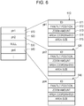
- Fig. 6 illustrates an example of a data structure of setting information saved in the recording unit 110.
- plural pieces of setting information 510, 520, 530, 540, ⁇ can be saved in the recording unit 110.
- an ID 511 included in the setting information 510 is identification information for identifying the setting information.
- Pan/tilt information 512 indicates the pan/tilt position of the camera 100 at a time when this setting information is created
- zoom information 513 indicates a zoom amount of the camera 100 at a time when this setting information is created.
- area coordinates 514 correspond to information indicating a position of the specified area on the image
- an area size 515 corresponds to information indicating a size of the specified area on the image.
- the setting information includes the information indicating the position and the size of the specified area as the information related to the specified area.
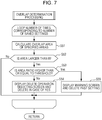
- Fig. 7 is a flow chart illustrating a procedure of the overlap determination processing executed in S5 in Fig. 5 .
- the system control unit 103 reads out the setting information related to the image analysis processing having the same type as the setting information created in S4 among the setting information previously set and saved in the recording unit 110.
- the system control unit 103 then repeats the processing in S51 to S55 the number of times corresponding to the number of read setting information.
- the system control unit 103 calculates the area of an overlapped area of the specified area included in the previous setting information and the specified area included in the new setting information. Specifically, the system control unit 103 first calculates the imaging direction and the viewing angle of the camera 100 on the basis of the pan/tilt information and the zoom information included in the previous setting information to be compared with the current imaging direction and the current viewing angle of the camera 100 and determines whether or not the imaging areas are overlapped with each other. At this time, when the imaging areas are not overlapped with each other, the system control unit 103 sets the area of the overlapped area of the specified areas as 0.
- the system control unit 103 determines the presence or absence of the overlapped area of the specified areas on the basis of the position and the size of the specified area included in the previous setting information and the position and the size of the specified area included in the new setting information. At this time, the system control unit 103 determines the presence or absence of the overlapped area of the specified areas by using the coordinates of both positions and the viewing angles in combination. In a case where the specified areas are overlapped with each other, the area of the overlapped area of the specified areas is calculated. An area ratio (%) is calculated as the ratio (%) of the specified area included in the new setting information which is included in the overlapped area.
- the system control unit 103 determines whether or not the area of the overlapped area which is calculated in S51 is larger than 0. In a case where it is determined that the area of the overlapped area is 0, the system control unit 103 shifts to the processing with respect to the next setting information. In a case where it is determined that the area of the overlapped area is larger than 0, the system control unit 103 determines that the overlap of the specified areas exists and shifts to S53.
- the system control unit 103 determines whether or not the area ratio calculated in S51 is higher than or equal to a previously set predetermined threshold. In a case where it is determined that the area ratio is lower than the threshold, the system control unit 103 shifts to S54. In a case where it is determined that the area ratio is higher than or equal to the threshold, the system control unit 103 shifts to S55.
- the system control unit 103 performs processing for urging the user to select whether or not the previous setting information is to be deleted.
- the system control unit 103 performs display control for displaying, for example, a delete operation selecting screen 410 illustrated in Fig. 8 on the display unit 201 of the client apparatus 200 and urges the user to select whether or not the previous setting information is to be deleted.
- the system control unit 103 then obtains the selection result of the user with respect to the delete operation selecting screen 410 and executes the processing in accordance with the obtained selection result.
- the system control unit 103 deletes the previous setting information from the recording unit 110.
- the setting information 530 is deleted.
- the setting information 530 becomes "NULL". With this configuration, the setting information 530 is excluded from the setting information used for the image analysis processing.
- the system control unit 103 does not delete the previous setting information from the recording unit 110, and the previous setting information remains. That is, in this case, the application of the previous setting information recorded in the recording unit 110 remains as the setting information used for the image analysis processing.
- the system control unit 103 deletes the previous setting information from the recording unit 110 and notifies the user that the previous setting information has been deleted. At this time, the system control unit 103 performs display control for displaying, for example, a warning screen 420 illustrated in Fig. 9 on the display unit 201 of the client apparatus 200.
- the system control unit 103 executes the processing in S51 to S55 in sequence with respect to all the setting information of the same type, the processing in Fig. 7 is ended.
- the camera 100 obtains the new setting information created by the user operation and the previous setting information recorded in the recording unit 110 corresponding to the setting information related to the image analysis processing of the same type as the new setting information.
- the camera 100 performs display control for displaying the shot image on the display unit of the client apparatus 200 and accepts a specification of an area on the image displayed on the display unit, so that the new setting information can be created.
- the camera 100 determines the presence or absence of the overlapped area where the specified area included in the new setting information and the specified area included in the previous setting information are overlapped with each other and decides processing to be executed with respect to at least one of the new setting information and the previous setting information in accordance with the determination result.
- the camera 100 determines the presence or absence of the overlapped area and calculates, in a case where it is determined that the overlapped area exists, the area ratio representing the overlap amount of the overlapped area to determine whether or not the calculated area ratio is higher than or equal to the predetermined threshold.
- this area ratio is the area ratio of the specified area included in the new setting information which is included in the overlapped area.
- the camera 100 determines that the new setting information and the previous setting information may be respectively applied as the setting information used for the image analysis processing and records the new setting information created by the user operation in the recording unit 110.
- the camera 100 determines that the operation that is not desired by the user by the overlapped area may frequently occur and automatically excludes the previous setting information from the setting information used for the image analysis processing. That is, the previous setting information is automatically deleted from the recording unit 110.
- the camera 100 determines that the operation that is not desired by the user may occur to some extent due to the overlapped area and urges the user to select whether or not the previous setting information is to be excluded from the setting information used for the image analysis processing.
- the above-described image analysis processing can be set as the intrusion detection processing, for example.
- the notification of the intrusion detection event occurs plural times in the overlapped area.
- the notification of the intrusion detection event may occur outside the specified area included in the new setting information due to the influence of the specified area included in the previous setting information.
- the camera 100 deletes the previous setting information from the recording unit 110 and excludes the previous setting information from the setting information used for the image analysis processing.
- the new setting information can be created without keeping the unwanted setting information, and it is possible to suppress the occurrence of the operation that is not desired by the user.
- the camera 100 can urge the user to select whether or not the previous setting information is to be deleted.
- the overlap amount of the overlapped area is low, the overlap of the areas can be permitted in some cases depending on the user since the number of the undesired event notifications is decreased.
- the user is urged to select whether or not the previous setting information is to be deleted in S54 in a case where the area ratio of the overlapped area is lower than the threshold.
- the user may be urged to select whether or not the new setting information is to be deleted, that is, whether or not the new setting information is to be recorded in the recording unit 110.
- the user may also be urged to select which one of the previous setting information and the new setting information is to be deleted.
- the user decides the direction and the viewing angle for the imaging by the camera, and the user can specify the area on the shot image displayed on the screen.
- the imaging direction and the viewing angle which are previously set and the imaging direction and the viewing angle of the image currently displayed on the screen are different from each other, it is difficult for the user to specify the area while checking the position and the size of the previously specified area.
- the area tends to be specified in the overlapped position.
- a phenomenon may occur where the result desired by the user is not obtained in the network camera function.
- the overlap of the specified areas included in the setting information of the same type is determined, and the processing in accordance with the determination result is decided. For this reason, even in a case where the user unintendedly sets the overlapped specified area, the new setting information can be created without keeping the unwanted setting information. Therefore, according to the present embodiment, it is possible to appropriately create the setting information including the area specification without impairing the operation desired by the user in the function setting of the network camera. In addition, the user does not need to remember the specified area that has been previously set by itself, and load of the user is also alleviated.
- the setting information may include time information indicating a time when this setting information is created.
- time information indicating a time when this setting information is created.
- an order of the setting information to be set as a deletion processing target may be decided on the basis of the above-described time information.
- the setting information having the old time may be deleted first in the deletion processing of the setting information.
- the determination result of the overlapped area may be displayed on the image displayed on the image display unit 401 of the function setting screen 400.
- the overlapped area may be superimposed on the image displayed on the image display unit 401 by graphics to be drawn.
- the area ratio of the overlapped area may also be displayed on the function setting screen 400.
- the viewing angle may be adjusted when necessary, and the specified area included in the previous setting information and the specified area included in the new setting information may be contained in the screen.
- the communication data amount reduction function based on the ROI specification is a function for reducing the communication data amount by decreasing a quality level of an image in an area outside the specified area and compressing and transmitting image data efficiently.
- the Q value is numeric value information representing the quantization amount at the time of the image compression.
- Fig. 10A illustrates an example in which, in a case where a setting 601 for adding 5 to the Q value outside the specified area 611 exists, a setting 602 for adding 10 to the Q value outside the specified area 612 is newly specified.
- a setting 601 for adding 5 to the Q value outside the specified area 611 exists
- a setting 602 for adding 10 to the Q value outside the specified area 612 is newly specified.
- processing is operated such that the communication data amount is decreased as compared with that before the setting.
- Fig. 10B illustrates an example in which, in a case where a setting 603 for adding 10 to the Q value outside the specified area 613 exists, a setting 604 for adding 5 to the Q value outside the specified area 614 is newly specified.
- a setting 603 for adding 10 to the Q value outside the specified area 613 exists
- a setting 604 for adding 5 to the Q value outside the specified area 614 is newly specified.
- processing is operated such that the communication data amount is increased as compared with that before the setting.
- a disadvantage from the increase in the communication data amount it is expected that a transmittable band is unnecessarily consumed and the data recording capacity is increased, for example.
- the processing to be executed next is decided by taking into account the contents of the new setting information.
- the flow of the function setting processing executed by the camera 100 according to the present embodiment is similar to that of Fig. 5 . It should be noted however that the procedure of the overlapped area determination processing in S5 differs.
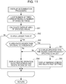
- Fig. 11 is a flow chart illustrating a procedure of the overlapped area determination processing executed by the camera 100 in S5 in Fig. 5 .
- This processing in Fig. 11 is similar to the processing in Fig. 7 except that the processing in S61 is added. Therefore, the part that executes the same processing as that in Fig. 7 is assigned with the same step number as that in Fig. 7 , and a part where the processing is different will be mainly described below.
- the system control unit 103 shifts to S61 and determines whether or not the Q value specified when the user specifies the area this time is higher than the previously specified Q value. Specifically, the system control unit 103 determines a magnitude relationship between the Q value included in the previous setting information which is read out from the recording unit 110 and the Q value included in the new setting information.
- the system control unit 103 shifts to S55 and executes the processing for deleting the previous setting information.
- the warning screen 420 ( Fig. 9 ) for notifying that the setting information has been deleted is presented to the user.
- the system control unit 103 shifts to S54 and presents the delete operation selecting screen 410 ( Fig. 8 ) for urging the user to select whether or not the previous setting information is to be deleted.
- the camera 100 determines the magnitude relationship between the Q value included in the new setting information and the Q value included in the previous setting information. Then, the processing to be executed is decided in accordance with the determination result. Specifically, in a case where it is determined that the Q value included in the new setting information is higher than the Q value included in the previous setting information, the camera 100 deletes the previous setting information from the recording unit 110. With this configuration, it becomes possible to create the new setting information without impairing the reduction effect of the communication data amount.
- VCA functions using a result of an image analysis inside the camera have been mounted to the network camera of recent years.
- Representative functions include moving object detection, intrusion detection, head count, and the like.
- the processing to be executed next is decided by taking into account the type of the VCA function corresponding to the setting target.
- the flow of the function setting processing executed by the camera 100 according to the present embodiment is similar to that of Fig. 5 . It should be noted however that the procedure of the overlapped area determination processing in S5 differs.
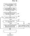
- Fig. 12 is a flow chart illustrating a procedure of the overlapped area determination processing executed by the camera 100 in S5 in Fig. 5 .
- This processing in Fig. 12 is similar to the processing in Fig. 7 except that the processing in S53 is deleted and the processing in S71 is added. Therefore, the part that executes the same processing as that in Fig. 7 is assigned with the same step number as that in Fig. 7 , and a part where the processing is different will be mainly described below.
- the system control unit 103 determines that the overlap of the areas exists in a case where it is determined in S52 that the area of the overlapped area is larger than 0 and shifts to S71.
- the system control unit 103 determines whether or not the type of the VCA function selected by the user is the type with which the overlap of the areas is permitted.
- the type with which the overlap of the areas is permitted includes the moving object detection.
- the type with which the overlap of the areas is not permitted includes the head count and the intrusion detection. It should be noted that a configuration may also be adopted in which the user can set whether or not each of the respective VCA functions is the type with which the overlap of the areas is permitted.
- the system control unit 103 shifts to S54 and presents the delete operation selecting screen 410 ( Fig. 8 ) for urging the user to select whether or not the previous setting information is to be deleted to the user.
- the system control unit 103 shifts to S55 and executes the processing for deleting the previous setting information.
- the system control unit 103 presents the warning screen 420 ( Fig. 7 ) for notifying the user that the setting information has been deleted.
- the camera 100 determines the type of the VCA function, that is, the type of the image analysis processing in which the new setting information is used. Then, the processing to be executed is decided depending on whether or not the type of the VCA function is the type with which the overlap of the areas between the setting information is permitted. With this configuration, in the case of the VCA function in which the overlap of the areas between the setting information is not permitted, it is possible to delete the previous setting information and appropriately create the new setting information.
- the processing for urging the user to select whether or not the previous setting information is to be deleted.
- the processing for urging the user to select whether or not the new setting information is to be deleted that is, whether or not the new setting information is to be recorded in the recording unit 110 may be performed.
- the user may also be urged to select which one of the previous setting information and the new setting information is to be deleted.
- an operation flag for switching valid/invalid statuses is prepared for each setting information to improve convenience of the function setting.
- this operation flag the user can invalidate the camera function without deleting the setting information.
- the user can also operate the camera function again by simply validating the operation flag.
- the flow of the function setting processing executed by the camera 100 according to the present embodiment is similar to that of Fig. 5 . It should be noted however that the procedure of the overlapped area determination processing in S5 differs.
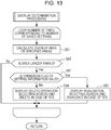
- Fig. 13 is a flow chart illustrating a procedure of the overlapped area determination processing executed by the camera 100 in S5 in Fig. 5 .
- This processing in Fig. 13 is similar to the processing in Fig. 7 except that the processing in S53 and the processing in S55 are deleted, and the processing in S81 and the processing in S82 are added. Therefore, the part that executes the same processing as that in Fig. 7 is assigned with the same step number as that in Fig. 7 , and a part where the processing is different will be mainly described below.
- the system control unit 103 determines that the overlap of the areas exists in a case where it is determined in S52 that the area of the overlapped area is larger than 0 and shifts to S81 to check the flag information included in the previous setting information. In a case where it is determined that the operation flag of the previous setting information is valid, the system control unit 103 shifts to S82. In a case where it is determined that the operation flag of the previous setting information is invalid, the system control unit 103 shifts to S54.
- the system control unit 103 performs the processing for urging the user to select whether or not the operation flag of the previous setting information is to be invalidated to exclude the previous setting information from the setting information used for the image analysis processing.
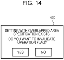
- the system control unit 103 performs display control for displaying, for example, an invalidation selecting screen 430 illustrated in Fig. 14 on the display unit 201 of the client apparatus 200 and urges the user to select whether or not the operation flag of the previous setting information is to be invalidated.
- the system control unit 103 obtains the selection result of the user with respect to the invalidation selecting screen 430 and executes the processing in accordance with the obtained selection result.
- the camera 100 determines the flag information included in the previous setting information. Then, the processing executed is decided in accordance with the determination result. Specifically, in a case where the operation flag included in the previous setting information is valid, the user is urged to select whether or not the operation flag of the previous setting information is to be invalidated. On the other hand, in a case where the operation flag included in the previous setting information is invalid, since the probability that the previous setting information is unwanted setting information is high, the user is urged to select whether or not the previous setting information is to be deleted.
- an object in an image is detected by using an image recognition technology, and an area is specified on the basis of information of a position and a size of the detected object will be described.
- an object to be recognized includes constructions, road, green space, sea and river, mountain, sky, and the like.
- a priority is set to these object types, and the processing with respect to the setting information where the areas are overlapped with each other is decided in accordance with the priority.
- the objects are classified into a plurality of groups, and each priority is decided.
- object information of the road (including a sidewalk) is set as a group 1.
- Object information of the constructions such as a building or a house is set as a group 2.
- Object information of other objects is set as a group 3.
- the group 1 is set to have the highest priority since the area is specified for a purpose of human or vehicle detection or the ROI in many cases, and the group 2 and the group 3 are set to have the descending priority in the stated order.
- the above-described group classification result is added into the setting information as the object type. It should be noted that the user may manually specify the group.
- the flow of the function setting processing executed by the camera 100 according to the present embodiment is similar to that of Fig. 5 . It should be noted however that the procedure of the overlapped area determination processing in S5 differs.
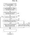
- Fig. 15 is a flow chart illustrating a procedure of the overlapped area determination processing executed by the camera 100 in S5 in Fig. 5 .
- This processing in Fig. 15 is similar to the processing in Fig. 7 except that the processing in S53 is deleted and the processing in S91 is added. Therefore, the part that executes the same processing as that in Fig. 7 is assigned with the same step number as that in Fig. 7 , and a part where the processing is different will be mainly described below.
- the system control unit 103 determines that the overlap of the areas exists in a case where it is determined in S52 that the area of the overlapped area is larger than 0 and shifts to S91.
- the system control unit 103 compares the object information included in the previous setting information with the object information included in the new setting information. In a case where it is determined that the priority of the object information included in the new setting information is lower than or equal to the priority of the object information included in the previous setting information, the system control unit 103 shifts to S54. On the other hand, in a case where it is determined that the priority of the object type included in the new setting information is higher than the priority of the object information included in the previous setting information, the system control unit 103 shifts to S55.
- the camera 100 determines the object information used for the decision on the specified area. Then, the processing to be executed is decided in accordance with the determination result.
- the processing with respect to the setting information where the area are overlapped with each other can be executed while the priority of the object type is taken into account, and it is possible to appropriately create the new setting information without impairing the operation desired by the user.
- the pieces of setting information corresponding to the comparison targets are not limited to the above and may be the mutual pieces of setting information related to the image analysis processing of the same type. That is, the plural pieces of setting information related to the image analysis processing of the same type which are recorded in a predetermined memory or the like may be compared with each other, or the plural pieces of setting information related to the image analysis processing of the same type which are continuously created by the user operation may be compared with each other.
- the exemplified embodiments of the present invention can also be realized by processing in which a program that realizes one or more functions of the above-described exemplified embodiments is supplied to a system or an apparatus via a network or a storage medium, and one or more processors in a computer of the system or the apparatus read out the program to be executed.
- the exemplified embodiments of the present invention can be realized by a circuit that realizes one or more functions (for example, an application specific integrated circuit (ASIC)).
- ASIC application specific integrated circuit
- the setting information including the area specification can be appropriately created, and it is possible to suppress the number of occasions where the undesired image analysis result is obtained.
- Embodiment(s) of the present invention can also be realized by a computer of a system or apparatus that reads out and executes computer executable instructions (e.g., one or more programs) recorded on a storage medium (which may also be referred to more fully as a 'non-transitory computer-readable storage medium') to perform the functions of one or more of the above-described embodiment(s) and/or that includes one or more circuits (e.g., application specific integrated circuit (ASIC)) for performing the functions of one or more of the above-described embodiment(s), and by a method performed by the computer of the system or apparatus by, for example, reading out and executing the computer executable instructions from the storage medium to perform the functions of one or more of the above-described embodiment(s) and/or controlling the one or more circuits to perform the functions of one or more of the above-described embodiment(s).
- computer executable instructions e.g., one or more programs
- a storage medium which may also be referred to more fully as
- the computer may comprise one or more processors (e.g., central processing unit (CPU), micro processing unit (MPU)) and may include a network of separate computers or separate processors to read out and execute the computer executable instructions.
- the computer executable instructions may be provided to the computer, for example, from a network or the storage medium.
- the storage medium may include, for example, one or more of a hard disk, a random-access memory (RAM), a read only memory (ROM), a storage of distributed computing systems, an optical disk (such as a compact disc (CD), digital versatile disc (DVD), or Blu-ray Disc (BD)TM), a flash memory device, a memory card, and the like.
Description
- The present invention relates to an information processing apparatus, an information processing method, and a storage medium.
- In recent years, various new functions have been mounted to a network camera, and setting items are prepared for each of the functions. The number of methods of specifying a partial area in a shot image by a user is increased as a method of setting the respective functions. For example, when a function of a privacy mask, a region of interest (ROI), moving object detection, intrusion detection, or the like is set, a method of specifying a predetermined area in an image is used.
- However, when the number of functions in the network camera is increased as described above, it becomes difficult for the user to remember a position or a size of the area that has been previously specified by the user itself. As a result, in a case where a plurality of specified areas are set with regard to the function settings of the same type, the specified areas may be overlapped with each other in some cases. In this case, there is a fear that a result desired by the user is not obtained in the network camera functions.
- To perform positioning of a plurality of cameras, Japanese Patent Laid-Open No.
2016-123004 - In addition, Japanese Patent No.
5555044 - For example, in the case of a function of reducing the communication data amount in an area outside the ROI, when the previously set specified area is contained in the newly set specified area, there is a fear that a bit rate in the newly set specified area may be unexpectedly decreased depending on setting contents. In the case of the intrusion detection function, when the previously set specified area and the newly set specified area are overlapped with each other, a notification of a detection event outside the newly set specified area may occur, or a notification of the detection event may occur plural times with respect to the same intruding object. In this manner, there is a fear that an operation that is not desired by the user may be caused.
US2017/0041608 discloses a method for setting Regions of Interest for quality adjustment in PTZ cameras, wherein a Region of Interest may change when PTZ control is executed. - In view of the above, an embodiment of the present invention aims at appropriately creating setting information including the area specification and suppressing the number of occasions where an undesired image analysis result is obtained.
- The present invention in its first aspect provides an information processing apparatus as specified in
claims 1 to 11. - The present invention in its second aspect provides an information processing method as specified in
claim 12. - The present invention in its third aspect provides a storage medium as specified in
claim 13. - Further features of the present invention will become apparent from the following description of embodiments with reference to the attached drawings.
-
-
Fig. 1 illustrates a network configuration example of an imaging system according to a present embodiment. -
Fig. 2 illustrates configuration examples of a network camera and a client apparatus. -
Fig. 3 illustrates a hardware configuration example of the network camera. -
Fig. 4 illustrates an example of a function setting screen of the network camera. -
Fig. 5 is a flow chart illustrating a procedure of function setting processing of the network camera. -
Fig. 6 illustrates an example of a data structure of setting information of the network camera. -
Fig. 7 is a flow chart illustrating a procedure of overlap determination processing. -
Fig. 8 illustrates an example of a delete operation selecting screen. -
Fig. 9 illustrates an example of a warning screen. -
Figs. 10A and 10B illustrate examples of Q value specification of a communication data amount reduction function based on ROI. -
Fig. 11 is a flow chart illustrating a procedure of the overlap determination processing according to a second embodiment. -
Fig. 12 is a flow chart illustrating a procedure of the overlap determination processing according to a third embodiment. -
Fig. 13 is a flow chart illustrating a procedure of the overlap determination processing according to a fourth embodiment. -
Fig. 14 illustrates an example of an invalidation selecting screen. -
Fig. 15 is a flow chart illustrating a procedure of the overlap determination processing according to a fifth embodiment. - Hereinafter, embodiments of the present invention will be described in detail with reference to the accompanying drawings.
- It should be noted that embodiments which will be described below are examples of the present invention and may be appropriately modified or altered depending on a configuration of an apparatus to which the present invention is applied or various conditions, and the present invention is not limited to the following description, but is rather defined by the appended claims.
-
Fig. 1 illustrates a network configuration example of animaging system 1000 according to the present embodiment. Theimaging system 1000 is provided with a network camera (hereinafter, which will be simply referred to as a "camera") 100 and aclient apparatus 200. Thecamera 100 and theclient apparatus 200 are connected to each other by anetwork 300 so as to be communicable with each other. Thenetwork 300 is constituted, for example, by a plurality of routers, switches, cables, and the like in conformity to Ethernet (registered trademark) communication specifications. It should be noted that, as long as the communication between thecamera 100 and theclient apparatus 200 can be performed by a configuration, any communication specifications, scales, and configurations of thenetwork 300 may be adopted. Thenetwork 300 may be realized by the internet, a wired local area network (LAN), a wireless LAN, a wide area network (WAN), or any combinations of those. - The
camera 100 is an imaging apparatus configured to image an imaging area. Thecamera 100 includes apan driving mechanism 100a, atilt driving mechanism 100b, and azoom driving mechanism 100c and functions as a pan tilt zoom (PTZ) camera constituted so as to be able to change the imaging area. Thepan driving mechanism 100a can change the imaging area of thecamera 100 in a pan direction and endlessly rotate thecamera 100 by 360°, for example. Thetilt driving mechanism 100b can change the imaging area of thecamera 100 in a tilt direction and rotate thecamera 100 from 0° in a horizontal direction to +180° in an upper direction, for example. Thezoom driving mechanism 100c can change the imaging area of thecamera 100 in a zoom direction and arbitrary change the viewing angle of thecamera 100. - It should be noted that the
camera 100 is not limited to the PTZ camera. In addition, thecamera 100 may be compatible to Power over Ethernet (PoE) and also have a configuration in which power is supplied via a LAN cable. Furthermore, inFig. 1 , thesingle camera 100 is connected to thenetwork 300, but a plurality of cameras can also be connected to thenetwork 300. - The
client apparatus 200 is constituted by a personal computer (PC) or a terminal apparatus such as a smart phone or a tablet-type PC and can transmit various commands to thecamera 100. The commands transmitted to thecamera 100 include a command for changing an imaging direction (bearing or orientation) of thecamera 100 and a viewing angle, a command for changing an imaging parameter, a command related to image processing, a command for starting transmission of an image, and the like. Theclient apparatus 200 also receives a response with respect to a command from thecamera 100. - The
camera 100 changes the imaging direction and the viewing angle in accordance with the command for changing the imaging direction and the viewing angle received from theclient apparatus 200. Thecamera 100 also transmits the image to theclient apparatus 200 in accordance with the command for starting the transmission of the image. In response to the above-described command for starting the transmission of the image, theclient apparatus 200 performs display control for receiving the image transmitted from thecamera 100 and presenting the received image to a user who uses theclient apparatus 200. -
Fig. 2 is a block diagram illustrating configuration examples of thecamera 100 and theclient apparatus 200. As illustrated inFig. 2 , thecamera 100 is provided with animaging unit 101, animage processing unit 102, asystem control unit 103, alens driving unit 104, alens control unit 105, apan driving unit 106, atilt driving unit 107, a pan/tilt control unit 108, and acommunication unit 109. Furthermore, thecamera 100 is provided with arecording unit 110 and anexternal input unit 111. Theclient apparatus 200 is provided with adisplay unit 201, aninput unit 202, asystem control unit 203, and acommunication unit 204. Thecommunication unit 109 of thecamera 100 and thecommunication unit 204 of theclient apparatus 200 are connected to each other via thenetwork 300 so as to be mutually communicable. - First, a configuration of the
camera 100 and functions of the respective units will be described. - The
imaging unit 101 is constituted by including a lens and imaging elements such as a complementary metal oxide semiconductor (CMOS) and a charge coupled device (CCD) and performs imaging of an object. Theimaging unit 101 also performs processing for converting an optical image focused on an imaging surface into digital electric signals by photoelectric conversion. Theimage processing unit 102 performs predetermined image processing with respect to the signal after the photoelectric conversion is performed in theimaging unit 101. The above-described image processing includes white balance processing, sharpness processing, and gray scale conversion processing. Theimage processing unit 102 also generates image data by performing compression coding of the image on which the above-described image processing has been performed and outputs the generated image data to thesystem control unit 103. - The
system control unit 103 analyzes the command received from theclient apparatus 200 via thecommunication unit 109 and performs processing in accordance with the command. Specifically, thesystem control unit 103 performs a change instruction of the image processing parameter with respect to theimage processing unit 102, an instruction for zoom or focus control with respect to thelens control unit 105, or an instruction for the pan/tilt operation with respect to the pan/tilt control unit 108 in accordance with the received command. Thesystem control unit 103 also generates a response with respect to the received camera control command and outputs the generated response to thecommunication unit 109 such that the response is to be transmitted to theclient apparatus 200. - Furthermore, the
system control unit 103 performs the image analysis processing with respect to the image received from theimage processing unit 102. Herein, the image analysis processing includes privacy mask processing, communication data amount reduction processing based on the ROI specification, moving object detection processing, intrusion detection processing, head count processing, removal detection processing, abandoning detection processing, prank detection processing, passing detection processing, automatic tracking processing, and the like. These image analysis processes are processes for realizing various camera functions. Thesystem control unit 103 may output a result of the above-described image analysis processing to thecommunication unit 109 such that the result and the image received from theimage processing unit 102 are to be transmitted to theclient apparatus 200. - In addition, according to the present embodiment, the
system control unit 103 creates setting information related to the above-described image analysis processing in accordance with the command received from theclient apparatus 200 via thecommunication unit 109 and records this setting information in therecording unit 110. Herein, the above-described setting information includes information related to a predetermined specified area in the image and information related to the imaging direction and the viewing angle of thecamera 100 at a time when the above-described image is shot. In a case where the image analysis processing is the privacy mask processing, the above-described specified area is equivalent to a mask area for protecting privacy. In a case where the image analysis processing is the communication data amount reduction processing based on the ROI specification, the above-described specified area is equivalent to an area where the data amount is to be reduced or an area where the data amount is not to be reduced. Furthermore, in a case where the image analysis processing is the moving object detection processing, the intrusion detection processing, or the like, the above-described specified area is equivalent to a monitoring area for a moving object, an intruding object, or the like. - It should be noted that the above-described setting information is not limited to the above-described configuration and may include, for example, time information indicating a time when the setting information is created.
- The
lens driving unit 104 is constituted by a driving system such as a focus lens and a zoom lens and a motor serving as a driving source thereof, and an operation of thelens driving unit 104 is controlled by thelens control unit 105. Thelens control unit 105 controls thelens driving unit 104 on the basis of the instruction by thesystem control unit 103. Thepan driving unit 106 is constituted by a mechanism driving system that performs a pan operation and a motor serving as a driving source thereof, and an operation of thepan driving unit 106 is controlled by the pan/tilt control unit 108. Thetilt driving unit 107 is constituted by a mechanism driving system that performs a tilt operation and a motor serving as a driving source thereof, and an operation of thetilt driving unit 107 is controlled by the pan/tilt control unit 108. The pan/tilt control unit 108 controls thepan driving unit 106 and thetilt driving unit 107 on the basis of the instruction by thesystem control unit 103. - The
communication unit 109 receives the various commands transmitted from thecommunication unit 204 of theclient apparatus 200 via thenetwork 300 and transmits the received commands to thesystem control unit 103. Thecommunication unit 109 also transmits the image or the like to thecommunication unit 204 of theclient apparatus 200 via thenetwork 300 on the basis of the instruction by thesystem control unit 103. - The
recording unit 110 is a non-volatile memory that holds the setting information related to the image analysis processing for realizing the camera function. Theexternal input unit 111 is constituted by including a power button, various setting buttons, and the like, and the user can input various instructions to thecamera 100 by operating theexternal input unit 111. - Next, the configuration of the
client apparatus 200 and the functions of the respective units will be described. - The
display unit 201 of theclient apparatus 200 is constituted by including a monitor such as a liquid crystal display (LCD) and displays the image obtained from thecamera 100 and a graphic user interface (GUI) for performing camera control. Theinput unit 202 is constituted by including a key board and a pointing device such as a mouse, and the user of theclient apparatus 200 can input the various commands via the GUI by operating theinput unit 202. According to the present embodiment, the user of theclient apparatus 200 can specify the above-described specified area by operating theinput unit 202 via the GUI. - The
system control unit 203 performs display control for displaying the image received from thecamera 100 via thecommunication unit 204 on thedisplay unit 201. Thesystem control unit 203 also generates various commands in accordance with the GUI operation by the user and outputs the generated commands to thecommunication unit 204 such that the commands are to be transmitted to thecamera 100. - The
communication unit 204 receives the image and signal transmitted from thecommunication unit 109 of thecamera 100 via thenetwork 300 and transmits the received information to thesystem control unit 203. Thecommunication unit 204 also transmits the above-described commands to thecommunication unit 109 of thecamera 100 via thenetwork 300 on the basis of the instruction of thesystem control unit 203. -
Fig. 3 illustrates a hardware configuration example of thecamera 100. - As illustrated in
Fig. 3 , thecamera 100 is provided with aCPU 11, aROM 12, aRAM 13, anexternal memory 14, animaging unit 15, aninput unit 16, a communication I/F 17, and asystem bus 18. TheCPU 11 is configured to control the operation in thecamera 100 in an overall manner and control the respective constituent units (12 to 17) via thesystem bus 18. TheROM 12 is a non-volatile memory that stores a control program or the like used for theCPU 11 to execute processing. It should be noted that the program may be stored in theexternal memory 14 or a detachably attachable storage medium (not illustrated). TheRAM 13 functions as a main memory of theCPU 11, a work area, or the like. That is, theCPU 11 loads the used program or the like from theROM 12 when the processing is executed onto theRAM 13 and executes the program or the like to realize the various function operations. - The
external memory 14 stores various data, various information, or the like used for theCPU 11 to perform the processing using the program, for example. Theexternal memory 14 also stores, for example, various data, various information, or the like obtained when theCPU 11 performs the processing using the program or the like. Theimaging unit 15 corresponds to theimaging unit 101 ofFig. 2 . Theinput unit 16 corresponds to theexternal input unit 111 ofFig. 2 . The communication I/F 17 corresponds to thecommunication unit 109 ofFig. 2 . A part or all of the functions of the respective elements of thecamera 100 illustrated inFig. 2 can be realized when theCPU 11 executes the program. It should be noted however that at least a part of the respective elements of thecamera 100 illustrated inFig. 2 may also be operated as dedicated-use hardware. In this case, the illustrated inFig. 2 is operated on the basis of the control of theCPU 11. - It should be noted that, in the case of the
client apparatus 200, the hardware configuration corresponding to thedisplay unit 201 ofFig. 2 is provided instead of theimaging unit 15 ofFig. 3 . Furthermore, in the case of theclient apparatus 200, the hardware configuration corresponding to theinput unit 202 ofFig. 2 is provided as theinput unit 16, and the hardware configuration corresponding to thecommunication unit 204 ofFig. 2 is provided as the communication I/F 17. A part or all of the functions of the respective elements of theclient apparatus 200 illustrated inFig. 2 can be realized when a CPU of theclient apparatus 200 corresponding to theCPU 11 executes the program. It should be noted however that at least a part of the respective elements of theclient apparatus 200 illustrated inFig. 2 may be operated as dedicated-use hardware. In this case, the dedicated-use hardware may be operated on the basis of the control by the CPU. - According to the present embodiment, the
camera 100 obtains information related to the specified area that is specified on the image displayed on thedisplay unit 201 of theclient apparatus 200 by the user to set the function of thecamera 100 and creates new setting information including information related to the obtained specified area. Thecamera 100 also compares the new setting information with the existing setting information saved in therecording unit 110 and determines whether or not the specified areas included in the respective pieces of the setting information are overlapped with each other. Thecamera 100 then decides processing to be executed with respect to at least one of the new setting information and the existing setting information in accordance with a determination result. Specifically, thecamera 100 saves the new setting information in therecording unit 110 to be applied as the setting information used for the image analysis processing and deletes the existing setting information from therecording unit 110 to be excluded from the setting information used for the image analysis processing in accordance with the above-described determination result. - According to the present embodiment, a case will be described where the
camera 100 functioning as the imaging apparatus operates as an information processing apparatus configured to create the setting information related to the image analysis processing and decide the processing at the time of the saving of the setting information. It should be noted however that theclient apparatus 200 may operate as the above-described information processing apparatus, and a general PC, another device, or the like may also operate as the above-described information processing apparatus. According to a second embodiment and subsequent embodiments too, theclient apparatus 200 may similarly operate as the information processing apparatus. -
Fig. 4 illustrates an example of afunction setting screen 400 for setting the function of thecamera 100 which is displayed on thedisplay unit 201 of theclient apparatus 200. - The
function setting screen 400 is constituted by including animage display unit 401, aPTZ operation unit 402, and asetting creation unit 403. The image shot by thecamera 100 is displayed on theimage display unit 401. It should be noted that video currently shot by thecamera 100 or previously recorded video is displayed on theimage display unit 401. ThePTZ operation unit 402 is constituted by a plurality of GUIs for performing the PTZ operation of thecamera 100. Thesetting creation unit 403 is constituted by the GUI for selecting an arbitrary setting item for creating the setting information from among a plurality of setting items. - The user can specify an arbitrary area in a display area of the
image display unit 401. The specification of the area can be realized by drawing a graphic form by using a mouse or the like, for example. In this case, for example, after aDRAW button 404 is selected, the user draws a graphic form in the display area of theimage display unit 401 and selects an arbitrary setting item of thesetting creation unit 403, so that it is possible to instruct to create setting information including information related to the specified area. After the graphic form is drawn in the display area of theimage display unit 401, the user can also delete the drawn graphic form by selecting aCLEAR button 405. - Next, the operation of the
camera 100 according to the present embodiment will be described. Herein, a case where the intrusion detection function of thecamera 100 is set will be described as an example. -
Fig. 5 is a flow chart illustrating a procedure of function setting processing executed by thecamera 100. This processing ofFig. 5 is started at a timing when the user operates the setting screen displayed on theclient apparatus 200 and instructs to start the creation of the setting information of the camera function. It should be noted however that the starting timing of the processing ofFig. 5 is not limited to the above-described timing. - The
camera 100 can realize respective processes illustrated inFig. 5 by reading out the program used by theCPU 11 to be executed. It should be noted however that the processing ofFig. 5 may also be realized when at least part of the respective elements of thecamera 100 illustrated inFig. 2 is operated as dedicated-use hardware. In this case, the dedicated-use hardware operates on the basis of the control of theCPU 11. Hereinafter, an alphabet S means a step in the flow chart. - First, in S1, the
system control unit 103 obtains a camera function corresponding to a creation target of the setting information specified by the user via thecommunication unit 109. Herein, the user can select the desired camera function by the operation with respect to thefunction setting screen 400 or the operation before thefunction setting screen 400 is displayed on theclient apparatus 200. - Next, in S2, the
system control unit 103 obtains information of the pan/tilt function and the zoom function of thePTZ operation unit 402 operated while checking the image displayed on theimage display unit 401 in thefunction setting screen 400 by the user via thecommunication unit 109. Thesystem control unit 103 then performs the instruction of the pan/tilt operation with respect to the pan/tilt control unit 108 and the instruction of the zoom operation with respect to thelens control unit 105 on the basis of the obtained information. With this configuration, the imaging direction and the viewing angle of thecamera 100 are changed. - In S3, the
system control unit 103 obtains information related to a range of the specified area that is specified in the display area of theimage display unit 401 by the user by operating the pointing device such as the mouse via thecommunication unit 109. This specified area is an area for detecting an object (for example, a person) intruding into the area as a monitoring target. In S4, when thesystem control unit 103 confirms that the user has selected an arbitrary setting item of thesetting creation unit 403 in thefunction setting screen 400 via thecommunication unit 109, thesystem control unit 103 creates new setting information on the basis of the information of the specified area obtained in S3 and temporarily saves the new setting information. - In S5, the
system control unit 103 determines the presence or absence of an overlap of the specified area included in the setting information previously created by the user and saved in therecording unit 110 and the specified area included in the new setting information and executes processing in accordance with the determination result. A detail of this overlap determination processing in S5 will be described below. In S6, thesystem control unit 103 saves the setting information created in S4 in therecording unit 110 corresponding to the non-volatile memory in accordance with the processing in S5. -
Fig. 6 illustrates an example of a data structure of setting information saved in therecording unit 110. According to the present embodiment, plural pieces of settinginformation recording unit 110. Herein, anID 511 included in the settinginformation 510 is identification information for identifying the setting information. Pan/tilt information 512 indicates the pan/tilt position of thecamera 100 at a time when this setting information is created, and zoominformation 513 indicates a zoom amount of thecamera 100 at a time when this setting information is created. Furthermore, area coordinates 514 correspond to information indicating a position of the specified area on the image, and anarea size 515 corresponds to information indicating a size of the specified area on the image. In this manner, the setting information includes the information indicating the position and the size of the specified area as the information related to the specified area. -
Fig. 7 is a flow chart illustrating a procedure of the overlap determination processing executed in S5 inFig. 5 . In this overlap determination processing, first, thesystem control unit 103 reads out the setting information related to the image analysis processing having the same type as the setting information created in S4 among the setting information previously set and saved in therecording unit 110. Thesystem control unit 103 then repeats the processing in S51 to S55 the number of times corresponding to the number of read setting information. - In S51, the
system control unit 103 calculates the area of an overlapped area of the specified area included in the previous setting information and the specified area included in the new setting information. Specifically, thesystem control unit 103 first calculates the imaging direction and the viewing angle of thecamera 100 on the basis of the pan/tilt information and the zoom information included in the previous setting information to be compared with the current imaging direction and the current viewing angle of thecamera 100 and determines whether or not the imaging areas are overlapped with each other. At this time, when the imaging areas are not overlapped with each other, thesystem control unit 103 sets the area of the overlapped area of the specified areas as 0. - On the other hand, in a case where the imaging areas are overlapped with each other, the
system control unit 103 determines the presence or absence of the overlapped area of the specified areas on the basis of the position and the size of the specified area included in the previous setting information and the position and the size of the specified area included in the new setting information. At this time, thesystem control unit 103 determines the presence or absence of the overlapped area of the specified areas by using the coordinates of both positions and the viewing angles in combination. In a case where the specified areas are overlapped with each other, the area of the overlapped area of the specified areas is calculated. An area ratio (%) is calculated as the ratio (%) of the specified area included in the new setting information which is included in the overlapped area. - In S52, the
system control unit 103 determines whether or not the area of the overlapped area which is calculated in S51 is larger than 0. In a case where it is determined that the area of the overlapped area is 0, thesystem control unit 103 shifts to the processing with respect to the next setting information. In a case where it is determined that the area of the overlapped area is larger than 0, thesystem control unit 103 determines that the overlap of the specified areas exists and shifts to S53. - In S53, the
system control unit 103 determines whether or not the area ratio calculated in S51 is higher than or equal to a previously set predetermined threshold. In a case where it is determined that the area ratio is lower than the threshold, thesystem control unit 103 shifts to S54. In a case where it is determined that the area ratio is higher than or equal to the threshold, thesystem control unit 103 shifts to S55. - In S54, the
system control unit 103 performs processing for urging the user to select whether or not the previous setting information is to be deleted. Herein, thesystem control unit 103 performs display control for displaying, for example, a deleteoperation selecting screen 410 illustrated inFig. 8 on thedisplay unit 201 of theclient apparatus 200 and urges the user to select whether or not the previous setting information is to be deleted. Thesystem control unit 103 then obtains the selection result of the user with respect to the deleteoperation selecting screen 410 and executes the processing in accordance with the obtained selection result. - That is, in a case where the user selects a "YES" button on the delete
operation selecting screen 410, thesystem control unit 103 deletes the previous setting information from therecording unit 110. For example, in a case where the specified area that is specified by the user on thefunction setting screen 400 and the specified area included in theprevious setting information 530 inFig. 6 are overlapped with each other and it is determined in S54 or S55 that the previous setting information is to be deleted, the settinginformation 530 is deleted. In this case, as illustrated inFig. 6 , the settinginformation 530 becomes "NULL". With this configuration, the settinginformation 530 is excluded from the setting information used for the image analysis processing. - On the other hand, in a case where the user selects a "NO" button on the delete
operation selecting screen 410, thesystem control unit 103 does not delete the previous setting information from therecording unit 110, and the previous setting information remains. That is, in this case, the application of the previous setting information recorded in therecording unit 110 remains as the setting information used for the image analysis processing. - In S55, the
system control unit 103 deletes the previous setting information from therecording unit 110 and notifies the user that the previous setting information has been deleted. At this time, thesystem control unit 103 performs display control for displaying, for example, awarning screen 420 illustrated inFig. 9 on thedisplay unit 201 of theclient apparatus 200. When thesystem control unit 103 executes the processing in S51 to S55 in sequence with respect to all the setting information of the same type, the processing inFig. 7 is ended. - As described above, the
camera 100 according to the present embodiment obtains the new setting information created by the user operation and the previous setting information recorded in therecording unit 110 corresponding to the setting information related to the image analysis processing of the same type as the new setting information. Thecamera 100 performs display control for displaying the shot image on the display unit of theclient apparatus 200 and accepts a specification of an area on the image displayed on the display unit, so that the new setting information can be created. Thecamera 100 then determines the presence or absence of the overlapped area where the specified area included in the new setting information and the specified area included in the previous setting information are overlapped with each other and decides processing to be executed with respect to at least one of the new setting information and the previous setting information in accordance with the determination result. - Specifically, the
camera 100 determines the presence or absence of the overlapped area and calculates, in a case where it is determined that the overlapped area exists, the area ratio representing the overlap amount of the overlapped area to determine whether or not the calculated area ratio is higher than or equal to the predetermined threshold. Herein, this area ratio is the area ratio of the specified area included in the new setting information which is included in the overlapped area. In a case where it is determined that the overlapped area does not exist, thecamera 100 determines that the new setting information and the previous setting information may be respectively applied as the setting information used for the image analysis processing and records the new setting information created by the user operation in therecording unit 110. - On the other hand, in a case where it is determined that the overlapped area exists and also the area ratio of the overlapped area is higher than or equal to the threshold, the
camera 100 determines that the operation that is not desired by the user by the overlapped area may frequently occur and automatically excludes the previous setting information from the setting information used for the image analysis processing. That is, the previous setting information is automatically deleted from therecording unit 110. In a case where it is determined that the area ratio of the overlapped area is lower than the threshold, thecamera 100 determines that the operation that is not desired by the user may occur to some extent due to the overlapped area and urges the user to select whether or not the previous setting information is to be excluded from the setting information used for the image analysis processing. - Herein, the above-described image analysis processing can be set as the intrusion detection processing, for example. In a case where plural pieces of setting information regarding to the intrusion detection processing are set and the overlapped area exists in the specified areas included in the respective pieces of the setting information, the notification of the intrusion detection event occurs plural times in the overlapped area. The notification of the intrusion detection event may occur outside the specified area included in the new setting information due to the influence of the specified area included in the previous setting information.
- Therefore, in a case where the image analysis processing is the intrusion detection processing and the overlapped area exists in the specified area, the
camera 100 deletes the previous setting information from therecording unit 110 and excludes the previous setting information from the setting information used for the image analysis processing. With this configuration, the new setting information can be created without keeping the unwanted setting information, and it is possible to suppress the occurrence of the operation that is not desired by the user. - In addition, as described above, in a case where the area ratio of the overlapped area is lower than the threshold, the
camera 100 can urge the user to select whether or not the previous setting information is to be deleted. In a case where the overlap amount of the overlapped area is low, the overlap of the areas can be permitted in some cases depending on the user since the number of the undesired event notifications is decreased. When the user can select whether or not the previous setting information is to be deleted, the user can more appropriately obtain the desired result. - It should be noted that, according to the present embodiment, the case has been described where the user is urged to select whether or not the previous setting information is to be deleted in S54 in a case where the area ratio of the overlapped area is lower than the threshold. However, the user may be urged to select whether or not the new setting information is to be deleted, that is, whether or not the new setting information is to be recorded in the
recording unit 110. The user may also be urged to select which one of the previous setting information and the new setting information is to be deleted. - In recent years, various new functions have been mounted to the network camera, and setting items are prepared for each of the functions. With regard to these respective functions, it is possible to save plural pieces of setting information including the information related to the specified area. In addition, some of cameras that can transmit a plurality of streams can save the above-described setting information for each stream. In this manner, a large number of pieces of setting information including the area specification are being saved inside the network camera. Then, it becomes difficult for the user to remember the position and the size of the specified area that has been previously set and saved.
- In addition, in the camera including the PTZ mechanism, the user decides the direction and the viewing angle for the imaging by the camera, and the user can specify the area on the shot image displayed on the screen. However, in this case, when the imaging direction and the viewing angle which are previously set and the imaging direction and the viewing angle of the image currently displayed on the screen are different from each other, it is difficult for the user to specify the area while checking the position and the size of the previously specified area.
- Therefore, in a case where the plurality of specified areas are set with regard to the function settings of the same type, the area tends to be specified in the overlapped position. When the plural pieces of setting information are used while the area is specified in the overlapped position, a phenomenon may occur where the result desired by the user is not obtained in the network camera function.
- In contrast to this, according to the present embodiment, the overlap of the specified areas included in the setting information of the same type is determined, and the processing in accordance with the determination result is decided. For this reason, even in a case where the user unintendedly sets the overlapped specified area, the new setting information can be created without keeping the unwanted setting information. Therefore, according to the present embodiment, it is possible to appropriately create the setting information including the area specification without impairing the operation desired by the user in the function setting of the network camera. In addition, the user does not need to remember the specified area that has been previously set by itself, and load of the user is also alleviated.
- It should be noted that, according to the present embodiment, the setting information may include time information indicating a time when this setting information is created. In this case, in a case where plural pieces of setting information in which the specified areas are overlapped with each other among the setting information of the same type as the new setting information, in S54 or S55, an order of the setting information to be set as a deletion processing target may be decided on the basis of the above-described time information. For example, the setting information having the old time may be deleted first in the deletion processing of the setting information. With this configuration, it becomes possible for the user to appropriately obtain a result desired at the current time.
- In addition, according to the present embodiment, in a case where piece of setting information where the specified areas are overlapped with each other exist, the determination result of the overlapped area may be displayed on the image displayed on the
image display unit 401 of thefunction setting screen 400. For example, the overlapped area may be superimposed on the image displayed on theimage display unit 401 by graphics to be drawn. At this time, the area ratio of the overlapped area may also be displayed on thefunction setting screen 400. At the time of the display of the overlapped area, the viewing angle may be adjusted when necessary, and the specified area included in the previous setting information and the specified area included in the new setting information may be contained in the screen. With this configuration, the user appropriately grasps the overlap state of the specified areas and can determine whether or not the previous setting information is to be deleted. - Next, a second embodiment of the present invention will be described.
- According to the above-described first embodiment, the case has been described where the setting of the intrusion detection function is performed. According to the second embodiment, a case where setting of the communication data amount reduction function based on the ROI specification is performed will be described. Herein, the communication data amount reduction function based on the ROI specification is a function for reducing the communication data amount by decreasing a quality level of an image in an area outside the specified area and compressing and transmitting image data efficiently. When an arbitrary value is added to a Q value of the area outside the specified area, it is possible to change the quality level of the image. The Q value is numeric value information representing the quantization amount at the time of the image compression. When the Q value is increased, a compression rate is increased, and the image quality is decreased.
- First, a setting example of the communication data amount reduction function based on the ROI specification will be described with reference to
Figs. 10A and 10B . -
Fig. 10A illustrates an example in which, in a case where a setting 601 for adding 5 to the Q value outside the specifiedarea 611 exists, a setting 602 for adding 10 to the Q value outside the specifiedarea 612 is newly specified. In this case, when the existing setting 601 is deleted and thenew setting 602 is adopted, processing is operated such that the communication data amount is decreased as compared with that before the setting. - On the other hand,
Fig. 10B illustrates an example in which, in a case where a setting 603 for adding 10 to the Q value outside the specifiedarea 613 exists, a setting 604 for adding 5 to the Q value outside the specifiedarea 614 is newly specified. In this case, when the existing setting 603 is deleted and anew setting 604 is adopted, processing is operated such that the communication data amount is increased as compared with that before the setting. As a disadvantage from the increase in the communication data amount, it is expected that a transmittable band is unnecessarily consumed and the data recording capacity is increased, for example. - That is, in a case where the overlap of the specified areas exists and the area ratio of the overlapped area is higher than or equal to the threshold, when the previous setting information is deleted and the new setting information is adopted, there is a fear that the communication data amount is increased and the user does not obtain the desired result depending on the contents of the new setting information.
- In view of the above, according to the present embodiment, in a case where the camera function corresponding to the setting target is the communication data amount reduction function based on the ROI specification, the processing to be executed next is decided by taking into account the contents of the new setting information.
- The flow of the function setting processing executed by the
camera 100 according to the present embodiment is similar to that ofFig. 5 . It should be noted however that the procedure of the overlapped area determination processing in S5 differs. -
Fig. 11 is a flow chart illustrating a procedure of the overlapped area determination processing executed by thecamera 100 in S5 inFig. 5 . This processing inFig. 11 is similar to the processing inFig. 7 except that the processing in S61 is added. Therefore, the part that executes the same processing as that inFig. 7 is assigned with the same step number as that inFig. 7 , and a part where the processing is different will be mainly described below. - In a case where it is determined in S53 that the area ratio of the overlapped area is higher than or equal to the threshold, the
system control unit 103 shifts to S61 and determines whether or not the Q value specified when the user specifies the area this time is higher than the previously specified Q value. Specifically, thesystem control unit 103 determines a magnitude relationship between the Q value included in the previous setting information which is read out from therecording unit 110 and the Q value included in the new setting information. - As described above, as the Q value is higher, the data amount reduction effect is higher. Therefore, in a case where it is determined that the Q value included in the new setting information is higher, the
system control unit 103 shifts to S55 and executes the processing for deleting the previous setting information. The warning screen 420 (Fig. 9 ) for notifying that the setting information has been deleted is presented to the user. On the other hand, in a case where it is determined that the Q value included in the new setting information is lower, thesystem control unit 103 shifts to S54 and presents the delete operation selecting screen 410 (Fig. 8 ) for urging the user to select whether or not the previous setting information is to be deleted. - As described above, in a case where the user sets a plurality of the communication data amount reduction functions based on the ROI, when it is determined that the specified areas are overlapped each other, the
camera 100 according to the present embodiment determines the magnitude relationship between the Q value included in the new setting information and the Q value included in the previous setting information. Then, the processing to be executed is decided in accordance with the determination result. Specifically, in a case where it is determined that the Q value included in the new setting information is higher than the Q value included in the previous setting information, thecamera 100 deletes the previous setting information from therecording unit 110. With this configuration, it becomes possible to create the new setting information without impairing the reduction effect of the communication data amount. - It should be noted that, according to the present embodiment, in S54, the case has been described where the user is urged to select whether or not the previous setting information is to be deleted. However, the user may be urged to select whether or not the new setting information is to be deleted, that is, whether or not the new setting information is to be recorded in the
recording unit 110. The user may also be urged to select which one of the previous setting information and the new setting information is to be deleted. - Next, a third embodiment of the present invention will be described.
- According to the above-described first embodiment, the case has been described where the intrusion detection function is set. According to the third embodiment, a case where various video contents analysis (VCA) functions are mounted to the
camera 100 will be described. - Along with an improvement in image processing performance, various VCA functions using a result of an image analysis inside the camera have been mounted to the network camera of recent years. Representative functions include moving object detection, intrusion detection, head count, and the like. When these VCA functions are set, a method of specifying the area like the above-described first embodiment is used.
- Functions in which a desired result is not obtained when a plurality of areas are specified to overlapped with each other in the function settings of the same type and functions in which the overlap of the areas is permitted exist among the above-described types of the VCA functions. For example, in the case of a function of counting the number of people in the image (head count function), since the count is incremented multiple times in a part where the areas are overlapped with each other, the correct head count is not measured. That is, the head count function does not permit the overlap of the areas. In contrast to this, with regard to the VCA function such as the moving object detection, the notification of the event occurs multiple times due to the overlap of the areas in some cases, but a critical phenomenon such as erroneous detection does not occur. Therefore, the overlap of the areas may be permitted in some cases depending on the user.
- In view of the above, according to the present embodiment, the processing to be executed next is decided by taking into account the type of the VCA function corresponding to the setting target.
- The flow of the function setting processing executed by the
camera 100 according to the present embodiment is similar to that ofFig. 5 . It should be noted however that the procedure of the overlapped area determination processing in S5 differs. -
Fig. 12 is a flow chart illustrating a procedure of the overlapped area determination processing executed by thecamera 100 in S5 inFig. 5 . This processing inFig. 12 is similar to the processing inFig. 7 except that the processing in S53 is deleted and the processing in S71 is added. Therefore, the part that executes the same processing as that inFig. 7 is assigned with the same step number as that inFig. 7 , and a part where the processing is different will be mainly described below. - The
system control unit 103 determines that the overlap of the areas exists in a case where it is determined in S52 that the area of the overlapped area is larger than 0 and shifts to S71. Thesystem control unit 103 determines whether or not the type of the VCA function selected by the user is the type with which the overlap of the areas is permitted. Herein, the type with which the overlap of the areas is permitted includes the moving object detection. On the other hand, the type with which the overlap of the areas is not permitted includes the head count and the intrusion detection. It should be noted that a configuration may also be adopted in which the user can set whether or not each of the respective VCA functions is the type with which the overlap of the areas is permitted. - In a case where it is determined S71 that the type of the VCA function is a type with which the overlap of the areas is permitted, the
system control unit 103 shifts to S54 and presents the delete operation selecting screen 410 (Fig. 8 ) for urging the user to select whether or not the previous setting information is to be deleted to the user. On the other hand, in a case where it is determined that the type of the VCA function is the type with which the overlap of the areas is not permitted, thesystem control unit 103 shifts to S55 and executes the processing for deleting the previous setting information. Thesystem control unit 103 presents the warning screen 420 (Fig. 7 ) for notifying the user that the setting information has been deleted. - It should be noted that, in a case where the type of the VCA function is determined as the type with which the overlap of the areas is permitted, a configuration may be adopted in which the delete
operation selecting screen 410 described above is not presented to the user, and the previous setting information regularly remains. - As described above, in a case where the user sets a plurality of the same VCA functions, when it is determined that the specified areas are overlapped with each other, the
camera 100 according to the present embodiment determines the type of the VCA function, that is, the type of the image analysis processing in which the new setting information is used. Then, the processing to be executed is decided depending on whether or not the type of the VCA function is the type with which the overlap of the areas between the setting information is permitted. With this configuration, in the case of the VCA function in which the overlap of the areas between the setting information is not permitted, it is possible to delete the previous setting information and appropriately create the new setting information. It should be noted that, according to the present embodiment, the case has been described where, when the overlapped area exists in the specified area and also the type of the VCA function is the type in which the overlap of the areas between the setting information is permitted, the processing for urging the user to select whether or not the previous setting information is to be deleted. However, the processing for urging the user to select whether or not the new setting information is to be deleted, that is, whether or not the new setting information is to be recorded in therecording unit 110 may be performed. The user may also be urged to select which one of the previous setting information and the new setting information is to be deleted. - Next, a fourth embodiment of the present invention will be described.
- According to the fourth embodiment, a case where an operation flag for switching valid/invalid statuses is prepared for each setting information to improve convenience of the function setting will be described. With this operation flag, the user can invalidate the camera function without deleting the setting information. The user can also operate the camera function again by simply validating the operation flag.
- The flow of the function setting processing executed by the
camera 100 according to the present embodiment is similar to that ofFig. 5 . It should be noted however that the procedure of the overlapped area determination processing in S5 differs. -
Fig. 13 is a flow chart illustrating a procedure of the overlapped area determination processing executed by thecamera 100 in S5 inFig. 5 . This processing inFig. 13 is similar to the processing inFig. 7 except that the processing in S53 and the processing in S55 are deleted, and the processing in S81 and the processing in S82 are added. Therefore, the part that executes the same processing as that inFig. 7 is assigned with the same step number as that inFig. 7 , and a part where the processing is different will be mainly described below. - The
system control unit 103 determines that the overlap of the areas exists in a case where it is determined in S52 that the area of the overlapped area is larger than 0 and shifts to S81 to check the flag information included in the previous setting information. In a case where it is determined that the operation flag of the previous setting information is valid, thesystem control unit 103 shifts to S82. In a case where it is determined that the operation flag of the previous setting information is invalid, thesystem control unit 103 shifts to S54. - In S82, the
system control unit 103 performs the processing for urging the user to select whether or not the operation flag of the previous setting information is to be invalidated to exclude the previous setting information from the setting information used for the image analysis processing. Herein, thesystem control unit 103 performs display control for displaying, for example, aninvalidation selecting screen 430 illustrated inFig. 14 on thedisplay unit 201 of theclient apparatus 200 and urges the user to select whether or not the operation flag of the previous setting information is to be invalidated. Then, thesystem control unit 103 obtains the selection result of the user with respect to theinvalidation selecting screen 430 and executes the processing in accordance with the obtained selection result. - As described above, in a case where the user sets plural pieces of setting information related to the image analysis processing, when it is determined that the specified areas are overlapped with each other, the
camera 100 according to the present embodiment determines the flag information included in the previous setting information. Then, the processing executed is decided in accordance with the determination result. Specifically, in a case where the operation flag included in the previous setting information is valid, the user is urged to select whether or not the operation flag of the previous setting information is to be invalidated. On the other hand, in a case where the operation flag included in the previous setting information is invalid, since the probability that the previous setting information is unwanted setting information is high, the user is urged to select whether or not the previous setting information is to be deleted. - With this configuration, it is possible to appropriately create the new setting information without impairing the operation desired by the user. Since the method of deleting the setting information in accordance with the flag information and the method of keeping the setting information by invalidating the operation flag are switched when the previous setting information is excluded from the setting information used for the image analysis processing, it is possible to appropriately delete the unwanted setting information from the
recording unit 110. - Next, a fifth embodiment of the present invention will be described.
- According to the fifth embodiment, a case where an object in an image is detected by using an image recognition technology, and an area is specified on the basis of information of a position and a size of the detected object will be described.
- For example, when an outdoor monitoring image is taken as an example, an object to be recognized includes constructions, road, green space, sea and river, mountain, sky, and the like. According to the present embodiment, a priority is set to these object types, and the processing with respect to the setting information where the areas are overlapped with each other is decided in accordance with the priority. Herein, the objects are classified into a plurality of groups, and each priority is decided.
- For example, in the case of the objects in the above-described monitoring image, object information of the road (including a sidewalk) is set as a
group 1. Object information of the constructions such as a building or a house is set as agroup 2. Object information of other objects is set as agroup 3. In this case, thegroup 1 is set to have the highest priority since the area is specified for a purpose of human or vehicle detection or the ROI in many cases, and thegroup 2 and thegroup 3 are set to have the descending priority in the stated order. The above-described group classification result is added into the setting information as the object type. It should be noted that the user may manually specify the group. - The flow of the function setting processing executed by the
camera 100 according to the present embodiment is similar to that ofFig. 5 . It should be noted however that the procedure of the overlapped area determination processing in S5 differs. -
Fig. 15 is a flow chart illustrating a procedure of the overlapped area determination processing executed by thecamera 100 in S5 inFig. 5 . This processing inFig. 15 is similar to the processing inFig. 7 except that the processing in S53 is deleted and the processing in S91 is added. Therefore, the part that executes the same processing as that inFig. 7 is assigned with the same step number as that inFig. 7 , and a part where the processing is different will be mainly described below. - The
system control unit 103 determines that the overlap of the areas exists in a case where it is determined in S52 that the area of the overlapped area is larger than 0 and shifts to S91. Thesystem control unit 103 compares the object information included in the previous setting information with the object information included in the new setting information. In a case where it is determined that the priority of the object information included in the new setting information is lower than or equal to the priority of the object information included in the previous setting information, thesystem control unit 103 shifts to S54. On the other hand, in a case where it is determined that the priority of the object type included in the new setting information is higher than the priority of the object information included in the previous setting information, thesystem control unit 103 shifts to S55. - As described above, in a case where the user sets plural pieces of setting information related to the image analysis processing, when it is determined that the specified areas are overlapped with each other, the
camera 100 according to the present embodiment determines the object information used for the decision on the specified area. Then, the processing to be executed is decided in accordance with the determination result. With this configuration, the processing with respect to the setting information where the area are overlapped with each other can be executed while the priority of the object type is taken into account, and it is possible to appropriately create the new setting information without impairing the operation desired by the user. - According to the above-described respective exemplified embodiments, the case has been described where the new setting information created by the user operation and the previous setting information recorded in the
recording unit 110 are compared with each other to determine the overlap of the specified areas. However, the pieces of setting information corresponding to the comparison targets are not limited to the above and may be the mutual pieces of setting information related to the image analysis processing of the same type. That is, the plural pieces of setting information related to the image analysis processing of the same type which are recorded in a predetermined memory or the like may be compared with each other, or the plural pieces of setting information related to the image analysis processing of the same type which are continuously created by the user operation may be compared with each other. - The exemplified embodiments of the present invention can also be realized by processing in which a program that realizes one or more functions of the above-described exemplified embodiments is supplied to a system or an apparatus via a network or a storage medium, and one or more processors in a computer of the system or the apparatus read out the program to be executed. In addition, the exemplified embodiments of the present invention can be realized by a circuit that realizes one or more functions (for example, an application specific integrated circuit (ASIC)).
- According to the exemplified embodiments of the present invention, the setting information including the area specification can be appropriately created, and it is possible to suppress the number of occasions where the undesired image analysis result is obtained.
- Embodiment(s) of the present invention can also be realized by a computer of a system or apparatus that reads out and executes computer executable instructions (e.g., one or more programs) recorded on a storage medium (which may also be referred to more fully as a 'non-transitory computer-readable storage medium') to perform the functions of one or more of the above-described embodiment(s) and/or that includes one or more circuits (e.g., application specific integrated circuit (ASIC)) for performing the functions of one or more of the above-described embodiment(s), and by a method performed by the computer of the system or apparatus by, for example, reading out and executing the computer executable instructions from the storage medium to perform the functions of one or more of the above-described embodiment(s) and/or controlling the one or more circuits to perform the functions of one or more of the above-described embodiment(s). The computer may comprise one or more processors (e.g., central processing unit (CPU), micro processing unit (MPU)) and may include a network of separate computers or separate processors to read out and execute the computer executable instructions. The computer executable instructions may be provided to the computer, for example, from a network or the storage medium. The storage medium may include, for example, one or more of a hard disk, a random-access memory (RAM), a read only memory (ROM), a storage of distributed computing systems, an optical disk (such as a compact disc (CD), digital versatile disc (DVD), or Blu-ray Disc (BD)™), a flash memory device, a memory card, and the like.
- While the present invention has been described with reference to embodiments, it is to be understood that the invention is not limited to the disclosed embodiments, but is rather defined by the claims.
Claims (13)
- An information processing apparatus comprising:obtaining means (103) configured to obtain first setting information including information related to a first specified area in an image captured by a pan tilt zoom camera (100) and related to image analysis processing and second setting information including information related to a second specified area in the image and related to the image analysis processing of the same type as the first setting information, wherein the first setting information and the second setting information include pan/tilt information (512) which indicates a pan/tilt position of the camera (100) at a time when the setting information was created, and zoom information (513) which indicates a zoom amount of the camera (100) at a time when the setting information is created, wherein the second setting information has been created before the first setting information;determination means (103) configured to calculate an overlapped area of the first specified area and the second specified area on a basis of the first setting information and the second setting information, by determining a second imaging direction and a second viewing angle of the camera (100) on the basis of the pan/tilt information and the zoom information included in the second setting information and comparing with a first imaging direction and a first viewing angle of the camera (100) determined on the basis of the pan/tilt information and the zoom information included in the first setting information, wherein the determination means is further configured to determine if the overlapped area is greater than zero; anddecision means (100) configured to decide processing to be executed with respect to at least one of the first setting information and the second setting information in accordance with a determination result of the determination means, wherein if the overlapped area is not greater than zero, first and second processing are not executed, and if the overlapped area is greater than zero, the decision means (100) decides whether to execute first processing or second processing,wherein the first processing comprises performing display control for displaying a delete operation selecting screen (410) for selecting whether or not to delete the second setting information, and deleting the second setting information if the user selects to delete the second setting information,and wherein the second processing comprises deleting the second setting information and performing display control for displaying a warning screen (420) notifying the user that the second setting information has been deleted.
- The information processing apparatus according to claim 1, further comprising:display control means (103) configured to display the image on a display unit (201),wherein the obtaining means is configured to accept a specification of an area on the image displayed by the display control means to obtain the first setting information.
- The information processing apparatus according to any preceding claim, further comprising:a recording unit (110) configured to store the setting information used for the image analysis processing,wherein the obtaining means is configured to obtain the second setting information from the recording unit (110) .
- The information processing apparatus according to any preceding claim, wherein, in a case where it is determined that the overlapped area is greater than zero, the determination means determines an overlap amount of the overlapped area.
- The information processing apparatus according to any preceding claim wherein, in a case where it is determined that the overlapped area is greater than zero, the determination means determines a type of the image analysis processing in which the first setting information and the second setting information are used.
- The information processing apparatus according to any preceding claim, wherein the first and second setting information further includes numeric value information representing a quantization amount for compressing an area outside the respective specified area in the image, and
wherein, in a case where it is determined that the overlapped area is greater than zero, the determination means determines a magnitude relationship between the numeric value information included in the first setting information and the numeric value information included in the second setting information. - The information processing apparatus according to claim 1, wherein the first and second setting information further includes flag information for setting a valid or invalid status of the setting information, and
wherein, in a case where it is determined that the overlapped area is greater than zero, the determination means determines the flag information included in the first setting information and the flag information included in the second setting information. - The information processing apparatus according to claim 1, wherein the first and second setting information further includes object information used for deciding the respective specified area in the image, and
wherein, in a case where it is determined that the overlapped area is greater than zero, the determination means determines the object information included in the first setting information and the object information included in the second setting information. - The information processing apparatus according to claim Claim 1, wherein the first and second setting information further includes time information indicating a time when the setting information is created, and
wherein the decision means decides an order of the setting information corresponding to a target of the processing to be executed on a basis of the time information. - The information processing apparatus according to claim 1, further comprising second display control means configured to cause display means to display the determination result of the determination means.
- The information processing apparatus according to any preceding claim, further comprising imaging means (101) configured to capture the image and changing means (106, 107, 108) configured to be able to change an imaging direction and a viewing angle of the imaging means.
- An information processing method related to image analysis processing, the information processing method comprising:obtaining first setting information including information related to a first specified area in an image captured by a pan tilt zoom camera and second setting information including information related to a second specified area in the image, wherein the first and second setting information is related to image analysis processing of the same type, wherein the first setting information and the second setting information include pan/tilt information (512) which indicates a pan/tilt position of the camera (100) at a time when the setting information was created, and zoom information (513) which indicates a zoom amount of the camera (100) at a time when the setting information is created, and the second setting information has been created before the first setting information;calculating an overlapped area of the first specified area and the second specified area on a basis of the obtained first setting information and the obtained second setting information by determining a second imaging direction and a second viewing angle of the camera (100) on the basis of the pan/tilt information and the zoom information included in the second setting information and comparing with a first imaging direction and a first viewing angle of the camera (100) determined on the basis of the pan/tilt information and the zoom information included in the first setting information, and determining if the overlapped area is greater than zero; anddeciding processing to be executed with respect to at least one of the first setting information and the second setting information in accordance with a result of the determining, wherein if the overlapped area is not greater than zero, first and second processing are not executed, and if the overlapped area is greater than zero, the method comprises deciding whether to execute first processing or second processing,wherein the first processing comprises performing display control for displaying a delete operation selecting screen (410) for selecting whether or not to delete the second setting information, and deleting the second setting information if the user selects to delete the second setting information,and wherein the second processing comprises deleting the second setting information and performing display control for displaying a warning screen (420) notifying the user that the second setting information has been deleted.
- A computer-readable storage medium that stores a program for causing a computer to execute an information processing method according to claim 12.
Applications Claiming Priority (1)
| Application Number | Priority Date | Filing Date | Title |
|---|---|---|---|
| JP2017154497A JP6938270B2 (en) | 2017-08-09 | 2017-08-09 | Information processing device and information processing method |
Publications (2)
| Publication Number | Publication Date |
|---|---|
| EP3442219A1 EP3442219A1 (en) | 2019-02-13 |
| EP3442219B1 true EP3442219B1 (en) | 2020-11-11 |
Family
ID=63371481
Family Applications (1)
| Application Number | Title | Priority Date | Filing Date |
|---|---|---|---|
| EP18188040.2A Active EP3442219B1 (en) | 2017-08-09 | 2018-08-08 | Information processing apparatus, information processing method, and storage medium |
Country Status (5)
| Country | Link |
|---|---|
| US (1) | US11012624B2 (en) |
| EP (1) | EP3442219B1 (en) |
| JP (1) | JP6938270B2 (en) |
| KR (1) | KR102307589B1 (en) |
| CN (1) | CN109391757B (en) |
Families Citing this family (7)
| Publication number | Priority date | Publication date | Assignee | Title |
|---|---|---|---|---|
| US10186124B1 (en) | 2017-10-26 | 2019-01-22 | Scott Charles Mullins | Behavioral intrusion detection system |
| JP2020160914A (en) * | 2019-03-27 | 2020-10-01 | 株式会社豊田自動織機 | Object detection device |
| KR20210153089A (en) | 2019-04-10 | 2021-12-16 | 스캇 찰스 멀린스 | monitoring system |
| JP7328849B2 (en) | 2019-09-25 | 2023-08-17 | キヤノン株式会社 | IMAGING DEVICE, SYSTEM, CONTROL METHOD OF IMAGING DEVICE, AND PROGRAM |
| JP2021052325A (en) * | 2019-09-25 | 2021-04-01 | キヤノン株式会社 | Image capture device, system, method for controlling image capture device, and program |
| JP7307643B2 (en) * | 2019-09-25 | 2023-07-12 | キヤノン株式会社 | IMAGING DEVICE, SYSTEM, CONTROL METHOD OF IMAGING DEVICE, AND PROGRAM |
| CN116761019A (en) * | 2023-08-24 | 2023-09-15 | 瀚博半导体(上海)有限公司 | Video processing method, system, computer device and computer readable storage medium |
Family Cites Families (27)
| Publication number | Priority date | Publication date | Assignee | Title |
|---|---|---|---|---|
| JPH07129586A (en) * | 1993-11-05 | 1995-05-19 | Sharp Corp | Information processor |
| US7542613B2 (en) * | 2004-09-21 | 2009-06-02 | Sanyo Electric Co., Ltd. | Image processing apparatus |
| US20070201749A1 (en) | 2005-02-07 | 2007-08-30 | Masaki Yamauchi | Image Processing Device And Image Processing Method |
| KR101187756B1 (en) * | 2005-11-07 | 2012-10-08 | 엘지전자 주식회사 | Method for controlling privacy mask display of monitoring camera |
| US8243797B2 (en) * | 2007-03-30 | 2012-08-14 | Microsoft Corporation | Regions of interest for quality adjustments |
| JP4508257B2 (en) * | 2008-03-19 | 2010-07-21 | ソニー株式会社 | Composition determination apparatus, composition determination method, and program |
| JP5237055B2 (en) * | 2008-11-07 | 2013-07-17 | キヤノン株式会社 | Video transmission apparatus, video transmission method, and computer program |
| JP2011048040A (en) * | 2009-08-26 | 2011-03-10 | Sony Corp | Video signal processing apparatus, method of processing video signal, and program |
| JP5709367B2 (en) * | 2009-10-23 | 2015-04-30 | キヤノン株式会社 | Image processing apparatus and image processing method |
| JP5566145B2 (en) * | 2010-03-18 | 2014-08-06 | キヤノン株式会社 | Image pickup apparatus having masking function and control method thereof |
| JP5555044B2 (en) | 2010-04-28 | 2014-07-23 | キヤノン株式会社 | Camera control device and camera system |
| JP5257958B2 (en) * | 2011-06-01 | 2013-08-07 | 株式会社日立メディコ | Image display device, image display system, and image display method |
| KR101793628B1 (en) | 2012-04-08 | 2017-11-06 | 삼성전자주식회사 | Transparent display apparatus and method thereof |
| JP6112479B2 (en) * | 2012-11-29 | 2017-04-12 | パナソニックIpマネジメント株式会社 | Surveillance camera device, surveillance system including the same, mask processing method, and mask processing program |
| JP2014144516A (en) * | 2013-01-30 | 2014-08-14 | Seiko Epson Corp | Robot control device, robot system, robot, control method and program |
| JP6273685B2 (en) * | 2013-03-27 | 2018-02-07 | パナソニックIpマネジメント株式会社 | Tracking processing apparatus, tracking processing system including the tracking processing apparatus, and tracking processing method |
| EP2813970A1 (en) * | 2013-06-14 | 2014-12-17 | Axis AB | Monitoring method and camera |
| JP6194791B2 (en) * | 2013-12-27 | 2017-09-13 | 富士ゼロックス株式会社 | Image processing apparatus and program |
| JP6705102B2 (en) | 2014-12-25 | 2020-06-03 | 三菱電機株式会社 | Imaging device installation support device, imaging device installation support method, and video recording/reproducing device |
| JP5988225B2 (en) * | 2015-02-25 | 2016-09-07 | パナソニックIpマネジメント株式会社 | Monitoring device and monitoring method |
| JP6650677B2 (en) * | 2015-02-26 | 2020-02-19 | キヤノン株式会社 | Video processing apparatus, video processing method, and program |
| JP6667240B2 (en) | 2015-07-31 | 2020-03-18 | キヤノン株式会社 | Apparatus, method, system and program. |
| JP6537396B2 (en) * | 2015-08-03 | 2019-07-03 | キヤノン株式会社 | IMAGE PROCESSING APPARATUS, IMAGING APPARATUS, AND IMAGE PROCESSING METHOD |
| KR101699014B1 (en) * | 2015-12-11 | 2017-01-23 | 재단법인대구경북과학기술원 | Method for detecting object using stereo camera and apparatus thereof |
| CN105744271B (en) | 2016-02-17 | 2018-06-26 | 浙江大华技术股份有限公司 | A kind of method for video coding and device |
| KR101674586B1 (en) * | 2016-05-10 | 2016-11-10 | 주식회사 와이앤엠시스템즈 | Method and Apparatus for Setting Image of PTZ Camera |
| KR102614012B1 (en) * | 2016-11-08 | 2023-12-14 | 한화비전 주식회사 | Aapparatus of processing image and method of providing image thereof |
-
2017
- 2017-08-09 JP JP2017154497A patent/JP6938270B2/en active Active
-
2018
- 2018-07-31 KR KR1020180088920A patent/KR102307589B1/en active IP Right Grant
- 2018-08-06 US US16/055,418 patent/US11012624B2/en active Active
- 2018-08-08 EP EP18188040.2A patent/EP3442219B1/en active Active
- 2018-08-09 CN CN201810902711.6A patent/CN109391757B/en active Active
Non-Patent Citations (1)
| Title |
|---|
| None * |
Also Published As
| Publication number | Publication date |
|---|---|
| US20190052814A1 (en) | 2019-02-14 |
| US11012624B2 (en) | 2021-05-18 |
| JP2019032763A (en) | 2019-02-28 |
| CN109391757A (en) | 2019-02-26 |
| CN109391757B (en) | 2021-06-18 |
| JP6938270B2 (en) | 2021-09-22 |
| EP3442219A1 (en) | 2019-02-13 |
| KR102307589B1 (en) | 2021-10-05 |
| KR20190016900A (en) | 2019-02-19 |
Similar Documents
| Publication | Publication Date | Title |
|---|---|---|
| EP3442219B1 (en) | Information processing apparatus, information processing method, and storage medium | |
| US9131122B2 (en) | Apparatus, method, system, and storage medium causing a display to display a graph indicating a degree of change of part of a captured image | |
| US8548202B2 (en) | Moving object detecting device, moving object detecting method, and computer program | |
| US20180144206A1 (en) | Setting apparatus, setting method, and storage medium | |
| US20150334299A1 (en) | Monitoring system | |
| US20160084932A1 (en) | Image processing apparatus, image processing method, image processing system, and storage medium | |
| US10079976B2 (en) | Display processing apparatus and method | |
| US20200045242A1 (en) | Display control device, display control method, and program | |
| US10643315B2 (en) | Information processing apparatus, information processing method, and recording medium | |
| EP3503021A1 (en) | Information processing device, system, information processing method, and storage medium | |
| JP2010092092A (en) | Image processing apparatus and image processing method | |
| US20230188679A1 (en) | Apparatus and method for transmitting images and apparatus and method for receiving images | |
| US11700446B2 (en) | Information processing apparatus, system, control method of information processing apparatus, and non-transitory computer-readable storage medium | |
| KR20120046509A (en) | Method and for apparatus for adjusting camera focus | |
| US10949713B2 (en) | Image analyzing device with object detection using selectable object model and image analyzing method thereof | |
| WO2013150734A1 (en) | Analysis system | |
| US20230199304A1 (en) | Information processing apparatus, information processing method, imaging apparatus, control method, and storage medium | |
| JP7130375B2 (en) | Image processing device, imaging device, image processing method, and program | |
| EP3855724B1 (en) | Control apparatus, control method, storage medium, and imaging control system | |
| US20230101516A1 (en) | Information processing apparatus, information processing method, and storage medium | |
| KR102328667B1 (en) | Method for video monitoring using surveillance area setting, Apparatus for video monitoring and Computer program for the same | |
| EP4195166A1 (en) | Apparatus and method for transmitting images and apparatus and method for receiving images | |
| US20210357676A1 (en) | Information processing apparatus, information processing method, and storage medium | |
| WO2013145531A1 (en) | Analysis system | |
| KR20210137617A (en) | Apparatus and method for searching color-based events |
Legal Events
| Date | Code | Title | Description |
|---|---|---|---|
| PUAI | Public reference made under article 153(3) epc to a published international application that has entered the european phase |
Free format text: ORIGINAL CODE: 0009012 |
|
| STAA | Information on the status of an ep patent application or granted ep patent |
Free format text: STATUS: THE APPLICATION HAS BEEN PUBLISHED |
|
| AK | Designated contracting states |
Kind code of ref document: A1 Designated state(s): AL AT BE BG CH CY CZ DE DK EE ES FI FR GB GR HR HU IE IS IT LI LT LU LV MC MK MT NL NO PL PT RO RS SE SI SK SM TR |
|
| AX | Request for extension of the european patent |
Extension state: BA ME |
|
| STAA | Information on the status of an ep patent application or granted ep patent |
Free format text: STATUS: REQUEST FOR EXAMINATION WAS MADE |
|
| STAA | Information on the status of an ep patent application or granted ep patent |
Free format text: STATUS: EXAMINATION IS IN PROGRESS |
|
| 17P | Request for examination filed |
Effective date: 20190813 |
|
| RBV | Designated contracting states (corrected) |
Designated state(s): AL AT BE BG CH CY CZ DE DK EE ES FI FR GB GR HR HU IE IS IT LI LT LU LV MC MK MT NL NO PL PT RO RS SE SI SK SM TR |
|
| 17Q | First examination report despatched |
Effective date: 20190906 |
|
| GRAP | Despatch of communication of intention to grant a patent |
Free format text: ORIGINAL CODE: EPIDOSNIGR1 |
|
| STAA | Information on the status of an ep patent application or granted ep patent |
Free format text: STATUS: GRANT OF PATENT IS INTENDED |
|
| INTG | Intention to grant announced |
Effective date: 20200604 |
|
| GRAS | Grant fee paid |
Free format text: ORIGINAL CODE: EPIDOSNIGR3 |
|
| GRAA | (expected) grant |
Free format text: ORIGINAL CODE: 0009210 |
|
| STAA | Information on the status of an ep patent application or granted ep patent |
Free format text: STATUS: THE PATENT HAS BEEN GRANTED |
|
| AK | Designated contracting states |
Kind code of ref document: B1 Designated state(s): AL AT BE BG CH CY CZ DE DK EE ES FI FR GB GR HR HU IE IS IT LI LT LU LV MC MK MT NL NO PL PT RO RS SE SI SK SM TR |
|
| REG | Reference to a national code |
Ref country code: GB Ref legal event code: FG4D |
|
| REG | Reference to a national code |
Ref country code: CH Ref legal event code: EP |
|
| REG | Reference to a national code |
Ref country code: AT Ref legal event code: REF Ref document number: 1334559 Country of ref document: AT Kind code of ref document: T Effective date: 20201115 |
|
| REG | Reference to a national code |
Ref country code: DE Ref legal event code: R096 Ref document number: 602018009568 Country of ref document: DE |
|
| REG | Reference to a national code |
Ref country code: IE Ref legal event code: FG4D |
|
| REG | Reference to a national code |
Ref country code: NL Ref legal event code: MP Effective date: 20201111 |
|
| REG | Reference to a national code |
Ref country code: AT Ref legal event code: MK05 Ref document number: 1334559 Country of ref document: AT Kind code of ref document: T Effective date: 20201111 |
|
| PG25 | Lapsed in a contracting state [announced via postgrant information from national office to epo] |
Ref country code: FI Free format text: LAPSE BECAUSE OF FAILURE TO SUBMIT A TRANSLATION OF THE DESCRIPTION OR TO PAY THE FEE WITHIN THE PRESCRIBED TIME-LIMIT Effective date: 20201111 Ref country code: RS Free format text: LAPSE BECAUSE OF FAILURE TO SUBMIT A TRANSLATION OF THE DESCRIPTION OR TO PAY THE FEE WITHIN THE PRESCRIBED TIME-LIMIT Effective date: 20201111 Ref country code: PT Free format text: LAPSE BECAUSE OF FAILURE TO SUBMIT A TRANSLATION OF THE DESCRIPTION OR TO PAY THE FEE WITHIN THE PRESCRIBED TIME-LIMIT Effective date: 20210311 Ref country code: GR Free format text: LAPSE BECAUSE OF FAILURE TO SUBMIT A TRANSLATION OF THE DESCRIPTION OR TO PAY THE FEE WITHIN THE PRESCRIBED TIME-LIMIT Effective date: 20210212 Ref country code: NO Free format text: LAPSE BECAUSE OF FAILURE TO SUBMIT A TRANSLATION OF THE DESCRIPTION OR TO PAY THE FEE WITHIN THE PRESCRIBED TIME-LIMIT Effective date: 20210211 |
|
| PG25 | Lapsed in a contracting state [announced via postgrant information from national office to epo] |
Ref country code: AT Free format text: LAPSE BECAUSE OF FAILURE TO SUBMIT A TRANSLATION OF THE DESCRIPTION OR TO PAY THE FEE WITHIN THE PRESCRIBED TIME-LIMIT Effective date: 20201111 Ref country code: BG Free format text: LAPSE BECAUSE OF FAILURE TO SUBMIT A TRANSLATION OF THE DESCRIPTION OR TO PAY THE FEE WITHIN THE PRESCRIBED TIME-LIMIT Effective date: 20210211 Ref country code: IS Free format text: LAPSE BECAUSE OF FAILURE TO SUBMIT A TRANSLATION OF THE DESCRIPTION OR TO PAY THE FEE WITHIN THE PRESCRIBED TIME-LIMIT Effective date: 20210311 Ref country code: PL Free format text: LAPSE BECAUSE OF FAILURE TO SUBMIT A TRANSLATION OF THE DESCRIPTION OR TO PAY THE FEE WITHIN THE PRESCRIBED TIME-LIMIT Effective date: 20201111 Ref country code: LV Free format text: LAPSE BECAUSE OF FAILURE TO SUBMIT A TRANSLATION OF THE DESCRIPTION OR TO PAY THE FEE WITHIN THE PRESCRIBED TIME-LIMIT Effective date: 20201111 Ref country code: SE Free format text: LAPSE BECAUSE OF FAILURE TO SUBMIT A TRANSLATION OF THE DESCRIPTION OR TO PAY THE FEE WITHIN THE PRESCRIBED TIME-LIMIT Effective date: 20201111 |
|
| REG | Reference to a national code |
Ref country code: LT Ref legal event code: MG9D |
|
| PG25 | Lapsed in a contracting state [announced via postgrant information from national office to epo] |
Ref country code: HR Free format text: LAPSE BECAUSE OF FAILURE TO SUBMIT A TRANSLATION OF THE DESCRIPTION OR TO PAY THE FEE WITHIN THE PRESCRIBED TIME-LIMIT Effective date: 20201111 |
|
| PG25 | Lapsed in a contracting state [announced via postgrant information from national office to epo] |
Ref country code: SM Free format text: LAPSE BECAUSE OF FAILURE TO SUBMIT A TRANSLATION OF THE DESCRIPTION OR TO PAY THE FEE WITHIN THE PRESCRIBED TIME-LIMIT Effective date: 20201111 Ref country code: EE Free format text: LAPSE BECAUSE OF FAILURE TO SUBMIT A TRANSLATION OF THE DESCRIPTION OR TO PAY THE FEE WITHIN THE PRESCRIBED TIME-LIMIT Effective date: 20201111 Ref country code: CZ Free format text: LAPSE BECAUSE OF FAILURE TO SUBMIT A TRANSLATION OF THE DESCRIPTION OR TO PAY THE FEE WITHIN THE PRESCRIBED TIME-LIMIT Effective date: 20201111 Ref country code: LT Free format text: LAPSE BECAUSE OF FAILURE TO SUBMIT A TRANSLATION OF THE DESCRIPTION OR TO PAY THE FEE WITHIN THE PRESCRIBED TIME-LIMIT Effective date: 20201111 Ref country code: RO Free format text: LAPSE BECAUSE OF FAILURE TO SUBMIT A TRANSLATION OF THE DESCRIPTION OR TO PAY THE FEE WITHIN THE PRESCRIBED TIME-LIMIT Effective date: 20201111 Ref country code: SK Free format text: LAPSE BECAUSE OF FAILURE TO SUBMIT A TRANSLATION OF THE DESCRIPTION OR TO PAY THE FEE WITHIN THE PRESCRIBED TIME-LIMIT Effective date: 20201111 |
|
| REG | Reference to a national code |
Ref country code: DE Ref legal event code: R097 Ref document number: 602018009568 Country of ref document: DE |
|
| PG25 | Lapsed in a contracting state [announced via postgrant information from national office to epo] |
Ref country code: DK Free format text: LAPSE BECAUSE OF FAILURE TO SUBMIT A TRANSLATION OF THE DESCRIPTION OR TO PAY THE FEE WITHIN THE PRESCRIBED TIME-LIMIT Effective date: 20201111 |
|
| PLBE | No opposition filed within time limit |
Free format text: ORIGINAL CODE: 0009261 |
|
| STAA | Information on the status of an ep patent application or granted ep patent |
Free format text: STATUS: NO OPPOSITION FILED WITHIN TIME LIMIT |
|
| 26N | No opposition filed |
Effective date: 20210812 |
|
| PG25 | Lapsed in a contracting state [announced via postgrant information from national office to epo] |
Ref country code: AL Free format text: LAPSE BECAUSE OF FAILURE TO SUBMIT A TRANSLATION OF THE DESCRIPTION OR TO PAY THE FEE WITHIN THE PRESCRIBED TIME-LIMIT Effective date: 20201111 Ref country code: NL Free format text: LAPSE BECAUSE OF FAILURE TO SUBMIT A TRANSLATION OF THE DESCRIPTION OR TO PAY THE FEE WITHIN THE PRESCRIBED TIME-LIMIT Effective date: 20201111 Ref country code: IT Free format text: LAPSE BECAUSE OF FAILURE TO SUBMIT A TRANSLATION OF THE DESCRIPTION OR TO PAY THE FEE WITHIN THE PRESCRIBED TIME-LIMIT Effective date: 20201111 |
|
| PG25 | Lapsed in a contracting state [announced via postgrant information from national office to epo] |
Ref country code: SI Free format text: LAPSE BECAUSE OF FAILURE TO SUBMIT A TRANSLATION OF THE DESCRIPTION OR TO PAY THE FEE WITHIN THE PRESCRIBED TIME-LIMIT Effective date: 20201111 |
|
| PG25 | Lapsed in a contracting state [announced via postgrant information from national office to epo] |
Ref country code: ES Free format text: LAPSE BECAUSE OF FAILURE TO SUBMIT A TRANSLATION OF THE DESCRIPTION OR TO PAY THE FEE WITHIN THE PRESCRIBED TIME-LIMIT Effective date: 20201111 |
|
| REG | Reference to a national code |
Ref country code: DE Ref legal event code: R119 Ref document number: 602018009568 Country of ref document: DE |
|
| REG | Reference to a national code |
Ref country code: CH Ref legal event code: PL |
|
| PG25 | Lapsed in a contracting state [announced via postgrant information from national office to epo] |
Ref country code: MC Free format text: LAPSE BECAUSE OF FAILURE TO SUBMIT A TRANSLATION OF THE DESCRIPTION OR TO PAY THE FEE WITHIN THE PRESCRIBED TIME-LIMIT Effective date: 20201111 |
|
| REG | Reference to a national code |
Ref country code: BE Ref legal event code: MM Effective date: 20210831 |
|
| PG25 | Lapsed in a contracting state [announced via postgrant information from national office to epo] |
Ref country code: LI Free format text: LAPSE BECAUSE OF NON-PAYMENT OF DUE FEES Effective date: 20210831 Ref country code: CH Free format text: LAPSE BECAUSE OF NON-PAYMENT OF DUE FEES Effective date: 20210831 |
|
| PG25 | Lapsed in a contracting state [announced via postgrant information from national office to epo] |
Ref country code: IS Free format text: LAPSE BECAUSE OF FAILURE TO SUBMIT A TRANSLATION OF THE DESCRIPTION OR TO PAY THE FEE WITHIN THE PRESCRIBED TIME-LIMIT Effective date: 20210311 Ref country code: LU Free format text: LAPSE BECAUSE OF NON-PAYMENT OF DUE FEES Effective date: 20210808 |
|
| PG25 | Lapsed in a contracting state [announced via postgrant information from national office to epo] |
Ref country code: IE Free format text: LAPSE BECAUSE OF NON-PAYMENT OF DUE FEES Effective date: 20210808 Ref country code: DE Free format text: LAPSE BECAUSE OF NON-PAYMENT OF DUE FEES Effective date: 20220301 Ref country code: BE Free format text: LAPSE BECAUSE OF NON-PAYMENT OF DUE FEES Effective date: 20210831 Ref country code: FR Free format text: LAPSE BECAUSE OF NON-PAYMENT OF DUE FEES Effective date: 20210831 |
|
| PG25 | Lapsed in a contracting state [announced via postgrant information from national office to epo] |
Ref country code: CY Free format text: LAPSE BECAUSE OF FAILURE TO SUBMIT A TRANSLATION OF THE DESCRIPTION OR TO PAY THE FEE WITHIN THE PRESCRIBED TIME-LIMIT Effective date: 20201111 |
|
| PG25 | Lapsed in a contracting state [announced via postgrant information from national office to epo] |
Ref country code: HU Free format text: LAPSE BECAUSE OF FAILURE TO SUBMIT A TRANSLATION OF THE DESCRIPTION OR TO PAY THE FEE WITHIN THE PRESCRIBED TIME-LIMIT; INVALID AB INITIO Effective date: 20180808 |
|
| PGFP | Annual fee paid to national office [announced via postgrant information from national office to epo] |
Ref country code: GB Payment date: 20230720 Year of fee payment: 6 |