JP6273685B2 - Tracking processing apparatus, tracking processing system including the tracking processing apparatus, and tracking processing method - Google Patents
Tracking processing apparatus, tracking processing system including the tracking processing apparatus, and tracking processing method Download PDFInfo
- Publication number
- JP6273685B2 JP6273685B2 JP2013066294A JP2013066294A JP6273685B2 JP 6273685 B2 JP6273685 B2 JP 6273685B2 JP 2013066294 A JP2013066294 A JP 2013066294A JP 2013066294 A JP2013066294 A JP 2013066294A JP 6273685 B2 JP6273685 B2 JP 6273685B2
- Authority
- JP
- Japan
- Prior art keywords
- tracking
- camera
- cameras
- information
- tracking information
- Prior art date
- Legal status (The legal status is an assumption and is not a legal conclusion. Google has not performed a legal analysis and makes no representation as to the accuracy of the status listed.)
- Active
Links
Images


Classifications
-
- G—PHYSICS
- G06—COMPUTING; CALCULATING OR COUNTING
- G06T—IMAGE DATA PROCESSING OR GENERATION, IN GENERAL
- G06T1/00—General purpose image data processing
-
- G—PHYSICS
- G06—COMPUTING; CALCULATING OR COUNTING
- G06T—IMAGE DATA PROCESSING OR GENERATION, IN GENERAL
- G06T7/00—Image analysis
- G06T7/20—Analysis of motion
- G06T7/292—Multi-camera tracking
-
- G—PHYSICS
- G08—SIGNALLING
- G08B—SIGNALLING OR CALLING SYSTEMS; ORDER TELEGRAPHS; ALARM SYSTEMS
- G08B25/00—Alarm systems in which the location of the alarm condition is signalled to a central station, e.g. fire or police telegraphic systems
-
- H—ELECTRICITY
- H04—ELECTRIC COMMUNICATION TECHNIQUE
- H04N—PICTORIAL COMMUNICATION, e.g. TELEVISION
- H04N7/00—Television systems
- H04N7/18—Closed-circuit television [CCTV] systems, i.e. systems in which the video signal is not broadcast
- H04N7/181—Closed-circuit television [CCTV] systems, i.e. systems in which the video signal is not broadcast for receiving images from a plurality of remote sources
-
- G—PHYSICS
- G06—COMPUTING; CALCULATING OR COUNTING
- G06T—IMAGE DATA PROCESSING OR GENERATION, IN GENERAL
- G06T2207/00—Indexing scheme for image analysis or image enhancement
- G06T2207/30—Subject of image; Context of image processing
- G06T2207/30196—Human being; Person
-
- G—PHYSICS
- G06—COMPUTING; CALCULATING OR COUNTING
- G06T—IMAGE DATA PROCESSING OR GENERATION, IN GENERAL
- G06T2207/00—Indexing scheme for image analysis or image enhancement
- G06T2207/30—Subject of image; Context of image processing
- G06T2207/30232—Surveillance
-
- G—PHYSICS
- G08—SIGNALLING
- G08B—SIGNALLING OR CALLING SYSTEMS; ORDER TELEGRAPHS; ALARM SYSTEMS
- G08B13/00—Burglar, theft or intruder alarms
- G08B13/18—Actuation by interference with heat, light, or radiation of shorter wavelength; Actuation by intruding sources of heat, light, or radiation of shorter wavelength
- G08B13/189—Actuation by interference with heat, light, or radiation of shorter wavelength; Actuation by intruding sources of heat, light, or radiation of shorter wavelength using passive radiation detection systems
- G08B13/194—Actuation by interference with heat, light, or radiation of shorter wavelength; Actuation by intruding sources of heat, light, or radiation of shorter wavelength using passive radiation detection systems using image scanning and comparing systems
- G08B13/196—Actuation by interference with heat, light, or radiation of shorter wavelength; Actuation by intruding sources of heat, light, or radiation of shorter wavelength using passive radiation detection systems using image scanning and comparing systems using television cameras
- G08B13/19602—Image analysis to detect motion of the intruder, e.g. by frame subtraction
- G08B13/19608—Tracking movement of a target, e.g. by detecting an object predefined as a target, using target direction and or velocity to predict its new position
Description
本発明は、複数のカメラによる撮影画像を用いて移動物体を追尾するための追尾処理装置及びこれを備えた追尾処理システム並びに追尾処理方法に関する。 The present invention relates to a tracking processing device for tracking a moving object using images captured by a plurality of cameras, a tracking processing system including the tracking processing device, and a tracking processing method.
従来、広域にわたって人物や車両等の移動物体を監視するために、移動物体が通行する複数の場所に設置されたカメラの撮影画像を取得し、それら撮影画像を用いて各カメラ内または複数のカメラ間で移動物体を追尾する追尾処理装置が存在する。この追尾処理装置による移動物体の追尾では、カメラと移動物体(追尾対象)との位置関係によってオクルージョン(すなわち、各カメラの撮影において手前に存在する他の物体によって背後の追尾対象が隠されてしまう状態)が発生し、その結果、撮影画像に基づく移動物体の追尾が困難となる場合がある。 Conventionally, in order to monitor a moving object such as a person or a vehicle over a wide area, a captured image of a camera installed at a plurality of places where the moving object passes is acquired, and each camera or a plurality of cameras is used by using the captured image. There is a tracking processing device that tracks moving objects in between. In tracking of a moving object by this tracking processing device, occlusion (that is, a tracking target behind the camera is hidden by other objects existing in front of each camera by the positional relationship between the camera and the moving object (tracking target)). State) occurs, and as a result, tracking of a moving object based on a captured image may be difficult.
そこで、そのようなオクルージョン等の影響を低減して高精度の追尾を可能とする技術が開発されている。例えば、互いに異なる視点から監視空間を撮影する複数のカメラを備え、現時刻における移動物体の予測位置と1つの監視カメラとの組み合わせを表した複数の仮説を設定し、尤度の高い仮説(すなわち、移動物体の追尾に適した仮説)に基づいて現時刻における移動物体の位置を求める追尾処理装置が知られている(特許文献1参照)。 Therefore, a technique has been developed that enables highly accurate tracking by reducing the influence of such occlusion and the like. For example, a plurality of cameras that capture a monitoring space from different viewpoints are set, a plurality of hypotheses representing combinations of the predicted position of a moving object at the current time and one monitoring camera are set, and a hypothesis having a high likelihood (ie, A tracking processing device that obtains the position of a moving object at the current time based on a hypothesis suitable for tracking of a moving object is known (see Patent Document 1).
ところで、カメラの視野(撮影範囲)には、監視空間に存在する障害物(壁及び柱等の建築物や、什器等)によって死角が生じることがあり、上記特許文献1に記載された従来技術では、そのような死角等を除いた範囲が有効撮影範囲として定められている。 By the way, in the field of view (shooting range) of the camera, a blind spot may occur due to an obstacle (a building such as a wall and a pillar, a fixture, etc.) existing in the surveillance space. In this case, a range excluding such blind spots is defined as an effective shooting range.
しかしながら、そのような有効撮影範囲においても、移動物体の向きが変化するなどして追尾処理に適さない追尾情報が撮影画像から取得される場合があり、特許文献1に記載された従来技術では、そのような追尾処理に適さない追尾情報が用いられると、複数のカメラ間での追尾対象の対応付けが難しくなって追尾処理の精度が著しく低下してしまうという問題がある。
However, even in such an effective shooting range, tracking information that is not suitable for the tracking process due to a change in the direction of the moving object or the like may be acquired from the shot image. In the related art described in
本発明は、このような従来技術の課題を鑑みて案出されたものであり、複数のカメラによる撮影画像を用いて移動物体を追尾する場合に、当該カメラ間での追尾処理の精度を向上させることを可能とした追尾処理装置及びこれを備えた追尾処理システム並びに追尾処理方法を提供することを主目的とする。 The present invention has been devised in view of such problems of the prior art, and when tracking a moving object using images captured by a plurality of cameras, the accuracy of the tracking process between the cameras is improved. It is a main object of the present invention to provide a tracking processing device, a tracking processing system including the tracking processing device, and a tracking processing method.
本発明の追尾処理装置は、複数のカメラによる撮影画像を用いて当該カメラ間で移動物体を追尾する追尾処理装置であって、前記各カメラに関し、前記撮影画像から取得された前記移動物体の画像情報を含む複数のカメラ内追尾情報を記憶する記憶手段と、前記各カメラに関し、前記撮影画像における無効領域を設定する無効領域設定手段と、前記複数のカメラ内追尾情報の絞り込みを行うことにより、前記複数のカメラ間での前記移動物体の追尾処理に用いるカメラ間追尾情報を抽出する絞り込み手段と、前記カメラ間追尾情報に基づき、前記複数のカメラ間で前記撮影画像における前記移動物体の対応付けを行う対応付け処理手段と、を備え、前記絞り込み手段は、前記複数のカメラ内追尾情報のうち前記無効領域内に位置する前記移動物体に関するカメラ内追尾情報を排除することにより前記絞り込みを行うことを特徴とする。 The tracking processing device according to the present invention is a tracking processing device that tracks a moving object between the cameras using images captured by a plurality of cameras, and the image of the moving object acquired from the captured image with respect to each camera. By storing a plurality of in-camera tracking information including information, for each of the cameras, an invalid area setting unit for setting an invalid area in the captured image, and by narrowing down the plurality of in-camera tracking information, Narrowing means for extracting tracking information between cameras used for tracking processing of the moving object between the plurality of cameras, and association of the moving object in the captured image between the plurality of cameras based on the tracking information between cameras and a correspondence processing means for performing said narrowing means, the moving positioned in the invalid area of the plurality of cameras in the tracking information And performing the narrowing by eliminating camera tracking information about the body.
本発明によれば、予め設定した無効領域内に位置する移動物体に関するカメラ内追尾情報を排除するため、複数のカメラ間での追尾処理に適さないカメラ内追尾情報を処理対象から簡易かつ確実に除外することができ、複数のカメラによる撮影画像を用いて移動物体を追尾する場合に、各カメラ間での追尾処理の精度を向上させることが可能となる。 According to the present invention, in- camera tracking information that is not suitable for tracking processing among a plurality of cameras is easily and reliably detected from a processing target in order to eliminate in-camera tracking information regarding a moving object located in a preset invalid area. In the case where a moving object is tracked using images captured by a plurality of cameras, it is possible to improve the accuracy of tracking processing between the cameras.
上記課題を解決するためになされた第1の発明は、複数のカメラによる撮影画像を用いて当該カメラ間で移動物体を追尾する追尾処理装置であって、前記各カメラに関し、前記撮影画像から取得された前記移動物体の画像情報を含む複数のカメラ内追尾情報を記憶する記憶手段と、前記各カメラに関し、前記撮影画像における無効領域を設定する無効領域設定手段と、前記複数のカメラ内追尾情報の絞り込みを行うことにより、前記複数のカメラ間での前記移動物体の追尾処理に用いるカメラ間追尾情報を抽出する絞り込み手段と、前記カメラ間追尾情報に基づき、前記複数のカメラ間で前記撮影画像における前記移動物体の対応付けを行う対応付け処理手段と、を備え、前記絞り込み手段は、前記複数のカメラ内追尾情報のうち前記無効領域内に位置する前記移動物体に関するカメラ内追尾情報を排除することにより前記絞り込みを行うことを特徴とする。 A first invention made to solve the above-described problems is a tracking processing device that tracks a moving object between cameras using images captured by a plurality of cameras, and is obtained from the captured images with respect to each camera. Storage means for storing a plurality of in-camera tracking information including image information of the moving object, an invalid area setting means for setting an invalid area in the captured image for each camera, and the plurality of in-camera tracking information The narrowing-down means for extracting the tracking information between the cameras used for the tracking process of the moving object between the plurality of cameras, and the captured image between the plurality of cameras based on the tracking information between the cameras. and a correspondence processing means for associating the moving object in the narrowing means, the invalid territory of the plurality of cameras in the tracking information And performing the narrowing by eliminating camera tracking information related to the moving object located within.
この第1の発明に係る追尾処理装置によれば、予め設定した無効領域(例えば、障害物が存在する領域)内に位置する移動物体に関するカメラ内追尾情報を排除するため、複数のカメラ間での追尾処理に適さないカメラ内追尾情報を処理対象から簡易かつ確実に除外することができ、複数のカメラ間での追尾処理(移動物体の対応付け処理)の精度を向上させることが可能となる。 According to the tracking processing device according to the first aspect of the present invention, in order to eliminate in-camera tracking information related to a moving object located in a preset invalid area (for example, an area where an obstacle exists), a plurality of cameras are In-camera tracking information that is not suitable for tracking processing can be easily and reliably excluded from processing targets, and the accuracy of tracking processing (moving object association processing) between a plurality of cameras can be improved. .
また、第2の発明では、上記第1の発明において、前記無効領域は、ユーザによって再設定可能であることを特徴とする。 According to a second aspect, in the first aspect , the invalid area can be reset by a user.
この第2の発明に係る追尾処理装置によれば、予め設定された無効領域をユーザが再設定可能であるため、無効領域の精度が向上し、複数のカメラ間での追尾処理に適さないカメラ内追尾情報を処理対象からより確実に除外することができる。 According to the tracking processing device according to the second aspect of the invention, since the user can reset the invalid area set in advance, the accuracy of the invalid area is improved and the camera is not suitable for the tracking process between a plurality of cameras. The inner tracking information can be more reliably excluded from the processing target.
また、第3の発明では、上記第1または第2の発明において、前記無効領域設定手段は、前記絞り込み手段によって過去に排除された前記カメラ内追尾情報に関する前記移動物体の位置情報に基づき、前記無効領域を設定することを特徴とする。 Further, in a third invention, in the first or second invention, the invalid area setting means is based on the position information of the moving object related to the in-camera tracking information that has been excluded in the past by the narrowing means. An invalid area is set.
この第3の発明に係る追尾処理装置によれば、過去に排除されたカメラ内追尾情報に関する移動物体の位置情報を利用して無効領域を設定するため、無効領域を簡易かつ高精度に設定することが可能となる。 According to the tracking processing device according to the third aspect of the invention, the invalid area is set using the position information of the moving object related to the in-camera tracking information excluded in the past, so the invalid area is set easily and with high accuracy. It becomes possible.
また、第4の発明では、上記第1から第3の発明のいずれかにおいて、前記対応付け処理手段の処理に関し、処理精度を優先する第1動作モードと、処理速度を優先する第2動作モードとを選択する動作モード選択手段を更に備え、前記対応付け処理手段は、前記第1動作モードが選択された場合、前記カメラ間追尾情報に基づき前記移動物体の対応付けを行う一方、前記第2動作モードが選択された場合、前記カメラ内追尾情報に基づき前記移動物体の対応付けを行うことを特徴とする。 According to a fourth invention, in any one of the first to third inventions, the first operation mode that prioritizes processing accuracy and the second operation mode that prioritizes processing speed in relation to the processing of the association processing means. The association processing means associates the moving object based on the inter-camera tracking information when the first operation mode is selected, while the second operation mode is selected. When the operation mode is selected, the moving object is associated based on the in-camera tracking information.
この第4の発明に係る追尾処理装置によれば、処理精度と処理速度との優先度合いに応
じて、対応付け処理手段の処理を適切に実行することができる。
According to the tracking processing device according to the fourth aspect of the invention, it is possible to appropriately execute the processing of the association processing means according to the priority degree between the processing accuracy and the processing speed.
また、第5の発明では、上記第1の発明において、前記移動物体の画像情報について前記複数のカメラ内追尾情報の相互の類似度を算出する類似度算出手段を更に備え、前記絞り込み手段は、前記複数のカメラ内追尾情報のうち前記類似度が相対的に低いカメラ内追尾情報を排除することにより前記絞り込みを行うことを特徴とする。
この第5の発明に係る追尾処理装置によれば、複数のカメラ内追尾情報について相互の類似度に基づき絞り込みを行うため、複数のカメラ間での追尾処理に適さないカメラ内追尾情報(オクルージョン等の問題が発生した移動物体の画像情報を含むもの)を処理対象から簡易かつ確実に除外することができる。
また、第6の発明では、上記第1から第5の発明のいずれかにおいて、前記複数のカメラ内追尾情報における前記移動物体の位置情報に基づき、当該移動物体の移動方向ベクトルを算出する移動方向算出手段を更に備え、前記絞り込み手段は、前記複数のカメラ間での前記移動方向ベクトルの角度の一致度合いに基づき、前記カメラ間追尾情報を抽出することを特徴とする。
According to a fifth aspect, in the first aspect, the image processing apparatus further includes similarity calculation means for calculating the similarity between the plurality of in-camera tracking information with respect to the image information of the moving object, and the narrowing down means includes: The narrowing down is performed by eliminating in-camera tracking information having a relatively low similarity among the plurality of in-camera tracking information.
According to the tracking processing device of the fifth aspect of the invention, since the plurality of tracking information within the camera is narrowed down based on the degree of similarity between them, the tracking information within the camera that is not suitable for the tracking processing between the plurality of cameras (occlusion etc. Can be easily and reliably excluded from the processing target.
According to a sixth aspect, in any one of the first to fifth aspects, a moving direction for calculating a moving direction vector of the moving object based on position information of the moving object in the plurality of in-camera tracking information. The information processing apparatus further includes a calculation unit, and the narrowing-down unit extracts the tracking information between cameras based on a degree of coincidence of angles of the moving direction vectors between the plurality of cameras.
この第6の発明に係る追尾処理装置によれば、移動物体の移動方向ベクトルの角度は移動物体の向きと一致する傾向にあるため、移動方向ベクトルの角度について相互に一致度合いが高いカメラ内追尾情報をカメラ間追尾情報として抽出することにより、各カメラ間での追尾処理の精度を向上させることが可能となる。 According to the tracking processing device of the sixth aspect of the invention, the angle of the moving direction vector of the moving object tends to coincide with the direction of the moving object. By extracting information as tracking information between cameras, it is possible to improve the accuracy of tracking processing between the cameras.
また、第7の発明では、上記第1から第6の発明のいずれかにおいて、前記対応付け処理手段による前記移動物体の対応付け結果をユーザに提示すると共に、当該対応付け結果の適否をユーザに判定させる結果提示手段を更に備えたことを特徴とする。 In the seventh invention, in any one of the first to sixth inventions, the association result of the moving object by the association processing unit is presented to the user, and whether or not the association result is appropriate is indicated to the user. The apparatus further includes a result presentation means for determining.
この第7の発明に係る追尾処理装置によれば、移動物体の対応付け結果の適否についてユーザに判定させるため、複数のカメラ間での追尾処理の精度をより向上させることが可能となる。 According to the tracking processing device according to the seventh aspect of the present invention, the accuracy of the tracking processing among a plurality of cameras can be further improved because the user determines whether or not the matching result of the moving object is appropriate.
また、第8の発明は、上記第1から第7の発明のいずれかに係る追尾処理装置と、前記複数のカメラと、前記カメラ内追尾情報を生成するカメラ内追尾装置とを備えた追尾処理システムである。 Further, an eighth invention is a tracking process comprising the tracking processing device according to any of the first to seventh inventions, the plurality of cameras, and an in-camera tracking device that generates the in-camera tracking information. System.
また、第9の発明は、複数のカメラによる撮影画像を用いて当該カメラ間で移動物体を追尾する追尾処理方法であって、前記各カメラに関し、前記撮影画像から取得された前記移動物体の画像情報を含む複数のカメラ内追尾情報を取得する追尾情報取得ステップと、前記各カメラに関し、前記撮影画像における無効領域を設定する無効領域設定ステップと、前記複数のカメラ内追尾情報の絞り込みを行うことにより、前記複数のカメラ間での前記移動物体の追尾処理に用いるカメラ間追尾情報を抽出する追尾情報絞り込みステップと、前記カメラ間追尾情報に基づき、前記複数のカメラ間で前記撮影画像における前記移動物体の対応付けを行う対応付け処理ステップと、を有し、前記追尾情報絞り込みステップは、前記複数のカメラ内追尾情報のうち前記無効領域内に位置する前記移動物体に関するカメラ内追尾情報を排除することにより前記絞り込みを行うことを特徴とする。
Further, a ninth invention is a tracking processing method for tracking a moving object between the cameras using images captured by a plurality of cameras, the image of the moving object acquired from the captured image with respect to each camera. A tracking information acquisition step for acquiring a plurality of in-camera tracking information including information, an invalid area setting step for setting an invalid area in the captured image for each of the cameras, and a narrowing down of the plurality of in-camera tracking information. The tracking information narrowing step for extracting tracking information between cameras used for tracking processing of the moving object between the plurality of cameras, and the movement of the captured image between the plurality of cameras based on the tracking information between the cameras. includes a correspondence processing step of performing a mapping of the object, wherein the tracking information narrowing step, the plurality of cameras in the tracking information Characterized in that said performing the narrowing by eliminating camera tracking information related to the moving objects located ineffective region of.
以下、本発明の実施の形態について図面を参照しながら説明する。 Hereinafter, embodiments of the present invention will be described with reference to the drawings.
図1は本発明の実施形態に係る追尾処理システムの構成図であり、図2は追尾処理システムにおけるカメラ配置の一例を示す説明図であり、図3は追尾処理システムのユーザによる(A)動作モード選択および(B)無効領域設定の説明図である。 FIG. 1 is a configuration diagram of a tracking processing system according to an embodiment of the present invention, FIG. 2 is an explanatory diagram showing an example of camera arrangement in the tracking processing system, and FIG. 3 is an operation (A) by a user of the tracking processing system. It is explanatory drawing of mode selection and (B) invalid area | region setting.
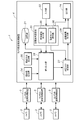
追尾処理システム1は、追尾対象となる人物や自動車等の移動物体を撮影する複数(ここでは、3台)のカメラ2と、各カメラ2にそれぞれ接続され、各カメラ2の撮影画像における移動物体の追尾処理(以下、「カメラ内追尾処理」という。)を行うカメラ内追尾処理装置3と、それらカメラ内追尾処理装置3による移動物体の追尾処理の結果(以下、「カメラ内追尾情報」という。)を取得し、複数のカメラ2間での追尾処理を行うカメラ間追尾処理装置4とを主として備える。なお、以下では、カメラ間での追尾処理およびカメラ間追尾処理装置4について、単に「追尾処理」および「追尾処理装置4」と称し、カメラ内追尾処理およびカメラ内追尾処理装置3とは区別する。
The
複数のカメラ2は、それぞれ監視用のビデオカメラからなり、カメラ内追尾処理装置3に対して複数の撮影画像(カラー動画)を順次送出する。各カメラ2は、監視が必要な場所を撮影可能なように、建物等の壁や天井などに設置される。本実施形態では、図2に示すように、通路11を通行する人物(移動物体)Hを追尾対象とし、撮影される人物Hの大きさや角度(身体の向き)が同程度となるように、各カメラ2の配置(すなわち、人物が移動する通路等の位置と各カメラとの位置関係)が定められている。また、各カメラ2は、撮影される人物Hの大きさや角度を調節するために、パン・チルト機能やズーム機能を備えている。
Each of the plurality of
各カメラ2の撮影方向は、ここでは鉛直方向(図面の上下方向)に対して斜め下方に傾斜して配置されているが、少なくとも追尾処理に必要な人物画像を取得可能な限りにおいて、各カメラ2の撮影方向は任意である。また、ここでは複数のカメラ2の視野(撮影範囲)12は互いに重複しないが、必要に応じて撮影視野を重複させた構成も可能である。さらに、追尾処理システム1に用いられるカメラの数は必要に応じて変更可能である。
Here, the shooting direction of each
カメラ内追尾処理装置3は、専用ケーブルやLAN等のネットワークによってカメラ2に接続されたPC(Personal Computer)からなるが、これに限らずサーバや、追尾処理を実行するマイクロコンピュータが組み込まれた電子機器等から構成されてもよい。ここでは各カメラ2に対して1台のカメラ内追尾処理装置3を設けたが、これに限らず複数のカメラ2の撮影画像を1台のカメラ内追尾処理装置3を用いてそれぞれ個別に処理してもよい。また、各カメラ2や後に詳述する追尾処理装置4にカメラ内追尾処理装置3の機能を付加した構成も可能である。
The in-camera tracking processing device 3 is composed of a PC (Personal Computer) connected to the
カメラ内追尾処理装置3は、カメラ2から入力した映像信号(撮影画像)に基づき、撮影された人物のカメラ内追尾処理を行う。このカメラ内追尾処理は、公知の人物追尾(追跡)技術を用いて行われる。例えば、カメラ内追尾処理装置3は、カメラ2の撮影画像と事前に取得した背景画像とを比較(画素毎の輝度値の差分を計算)すること(背景差分)により移動物体が存在する変化領域を抽出する。背景画像は、移動物体の写っていない撮影画像であり、各カメラ2によって事前に撮影されたものである。そして、カメラ内追尾処理装置3は、その変化領域において、公知の特徴量(例えば、HOG(Histogram of Oriented Gradient )特徴量)を用いて人物および背景の一部を包含する矩形の人物領域を検出する。また、カメラ内追尾処理装置3は、撮影画像毎に人物領域を検出し、公知のテンプレートマッチングや追跡フィルタ(例えば、パーティクルフィルタ)を用いて人物領域を追尾する。カメラ内追尾処理装置3は、検出した各人物画像(人物領域の画素情報)の情報及びその関連情報(人物の位置情報等)をカメラ内追尾情報として所定のメモリに格納する。
The in-camera tracking processing device 3 performs in-camera tracking processing of a photographed person based on the video signal (captured image) input from the
上記カメラ内追尾処理によって得られた複数のカメラ内追尾情報は、追尾処理装置4に対して順次送出される。なお、カメラ内追尾処理は上記の方法に限らず、例えば、撮影時間が前後する撮影画像において、フレーム間差分により動きが生じた画素の集合(領域)を人物として検出してもよい。撮影画像に異なる人物が複数存在する場合には、各人物についてカメラ内追尾情報が得られる。
A plurality of in-camera tracking information obtained by the in-camera tracking process is sequentially transmitted to the
追尾処理装置4は、専用ケーブルやLAN等のネットワークによってカメラ内追尾処理装置3に接続されたPCからなるが、これに限らずサーバや、追尾処理を実行するマイクロコンピュータが組み込まれた電子機器等から構成されてもよい。追尾処理装置4は、カメラ内追尾処理装置3から順次入力するカメラ内追尾情報を記憶する記憶部(記憶手段)21と、ユーザ入力情報に基づき追尾処理装置4における処理条件を設定する追尾条件設定部23とを有している。ユーザ入力情報は、ユーザによって入力部22を介して入力される。追尾条件設定部23において、無効領域設定部35は、ユーザ入力情報に基づき各カメラ2の撮影画像(撮影範囲)における無効領域を設定し、また、動作モード選択部(動作モード選択手段)36は、ユーザ入力情報に基づき対応付け処理部27の動作モード(第1動作モードまたは第2動作モード)を選択する。
The
また、追尾処理装置4は、各カメラ2に関し、複数のカメラ内追尾情報の相互の類似度を算出する類似度算出部(類似度算出手段)24と、複数のカメラ内追尾情報における人物の位置情報に基づき、人物の移動方向ベクトルを算出する移動方向算出部(移動方向算出手段)25と、各カメラ2に関し、複数のカメラ内追尾情報の絞り込みを行う(すなわち、不適切なカメラ内追尾情報を排除する)ことにより、各カメラ2間での人物の追尾処理に用いるべき追尾情報(以下、「カメラ間追尾情報」という。)を抽出する絞り込み部(絞り込み手段)26と、抽出されたカメラ間追尾情報に基づき、各カメラ2間で撮影画像における人物の対応付けを行う対応付け処理部(対応付け処理手段)27と、この対応付け処理部27による人物の対応付け結果をユーザに提示すると共に、当該対応付け結果の適否をユーザに判定させる追尾結果提示部(結果提示手段)28とを有している。そして、追尾結果提示部28での一連の人物の対応付け状況は出力部29を介してユーザに提示される。
The
出力部29は液晶ディスプレイからなり、入力部22はキーボードおよびマウスからなるが、これに限定されるものではなく、例えば、タッチパネルディスプレイなどの他の装置を用いて出力部29および入力部22を構成してもよい。
The
ユーザ入力情報には、後述する撮影画像における無効領域の位置及びサイズの情報と、対応付け処理部27の対応付けの処理についての動作モード(ここでは、高精度モードまたは高速モード)の選択情報とが少なくとも含まれる。
The user input information includes information on the position and size of the invalid area in the captured image, which will be described later, and selection information on the operation mode (here, high-precision mode or high-speed mode) for the association processing of the
カメラ間追尾情報には、カメラ2によって撮影された人物画像(人物領域の画素情報)の情報に加え、これに対応づけられた人物の位置、撮影時刻及び人物の移動方向のベクトルなどの関連情報が含まれる。人物の位置の情報は、人物領域の位置の履歴(人物の移動軌跡)によって構成される。人物の位置は、種々の公知の方法によって特定することができるが、ここでは、人の頭頂部の座標を人物の基準位置としている。
In the inter-camera tracking information, in addition to information of a person image (pixel information of a person area) photographed by the
追尾条件設定部23は、GUI(Graphical User Interface)機能を有しており、図3に示すように、ユーザは出力部29に表示させたユーザ入力画面において、入力部22を介して追尾条件等のユーザ入力情報の入力を行うことができる。図3(A)の対応付け処理に関する動作モード選択画面では、ユーザは、マウスクリックによって処理精度を優先する高精度モード(第1動作モード)および処理速度を優先する高速モード(第2動作モード)のいずれかを選択することができる。
The tracking
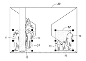
図3(B)の無効領域設定画面では、ユーザは、撮影画像(撮影範囲)30における無効領域31を設定することが可能である。より詳細には、ユーザは、撮影画像を観察しながら有効な人物画像が得られないと考える領域にマウスポインタを重ねてドラッグすることにより、無効領域31(撮影画像30中に網掛けで示された矩形領域)を設定することができる。
In the invalid area setting screen of FIG. 3B, the user can set the
無効領域31は、ユーザに確定される(例えば、ユーザが図示しない確定ボタンを押下する)までは候補領域として保持され、ユーザは適時再設定(位置やサイズの補正)を行うことが可能である。例えば、ユーザは、無効領域31(候補領域)内にマウスポインタを重ねてドラッグすることにより無効領域31を移動させることが可能であり、また、無効領域31を画定する各辺に示された■(黒四角)印のいずれかにマウスポインタを重ねてドラッグすることにより無効領域31のサイズを変更することができる。これに限らず、ユーザは、無効領域31を定める座標(例えば、矩形領域の四隅の座標)を入力することにより、無効領域31を設定(或いは再設定)してもよい。
The
なお、図3(B)に示した例では、オクルージョンが発生し易い塀32、電柱33及び街路樹34の周辺が無効領域として設定され得るが、これに限らず、ユーザは撮影エリアの状況に応じて他の障害物(建築物や什器等)の周辺を無効領域として設定することができる。また、無効領域としては、オクルージョンの発生し易い領域に限らず、人物の方向が他の場所とは異なる領域(例えば、主要な通路とは方向が異なる通路などの場所)や、暗い領域(例えば、日光や照明が遮られて人物が見え難い場所)や、カメラの撮影範囲の周縁部に位置することにより画像の信頼性が十分に得られない領域などが設定され得る。また、図3(B)では、1つの矩形の無効領域31のみが示されているが、無効領域31は任意の形状で任意の数(0の場合も含む)だけ設定することができる。設定された無効領域31の位置やサイズの情報は、後に詳述する追尾処理条件に関する設定データの一部を構成し、各カメラ2に対応づけられた無効領域マップとして記憶部21に記憶される。
In the example shown in FIG. 3B, the vicinity of the
類似度算出部24は、複数のカメラ内追尾情報について人物画像を比較することにより、カメラ内追尾情報の相互の類似度を評価する。より詳細には、類似度算出部24は、人物領域の全体または人物領域を分割した部分領域毎のRGBの色ヒストグラムを作成し、バタッチャリア(Bhattacharyya)係数を用いてそれらの類似度を算出する。色ヒストグラムは人物領域のサイズの違いによる影響を受け難くするために正規化される。また、人物領域を分割した場合には、各領域の類似度の平均によって色ヒストグラム間の類似度が比較される。
The
なお、類似度算出部24による類似度の算出(類似性の評価)は、ここに示したものに限らず、他の公知の方法を用いることができる。ただし、色ヒストグラムを用いることにより、人物画像間のサイズの違いの問題が生じることを回避できるという利点がある。また、類似度算出部24は、公知の方法(例えば人物に共通して存在する頭部、胴、脚等の外形に関する特徴量を用いて)人物画像の評価領域(例えば、頭部および胴)を特定し、その評価領域について類似度を算出してもよい。
Note that the similarity calculation (similarity evaluation) by the
後に詳述するが、絞り込み部26は、無効領域設定部35によって設定された無効領域マップを取得し、この無効領域マップに基づき複数のカメラ内追尾情報の絞り込みを行うことができる。つまり、絞り込み部26は、ユーザによって設定された無効領域内に存在する人物に関するカメラ内追尾情報を排除することにより、各カメラ2間での追尾処理に適さないカメラ内追尾情報を追尾処理の対象から簡易かつ確実に除外する。
As will be described in detail later, the narrowing-down
また、絞り込み部26は、類似度算出部24によって算出された類似度を取得し、この類似度に基づき複数のカメラ内追尾情報の絞り込みを行うことができる。つまり、絞り込み部26は、複数のカメラ内追尾情報について相互の類似度に基づき絞り込みを行うことにより、各カメラ2間での追尾処理に適さないカメラ内追尾情報(人物の向きが他の画像とは異なる画像や、オクルージョンが発生した画像等)を追尾処理の対象から簡易かつ確実に除外する。
Further, the narrowing-down
また、絞り込み部26は、移動方向算出部25によって算出された移動方向ベクトルを取得し、この移動方向ベクトルに基づき複数のカメラ内追尾情報の絞り込みを行うことができる。つまり、人物の進行方向を示す移動方向ベクトルの角度は、人物の向きと一致する傾向にあるため、絞り込み部26は、移動方向ベクトルの角度について相互に一致度合いが高いカメラ内追尾情報をカメラ間追尾情報として抽出することにより、各カメラ2間での追尾処理の精度を向上させる。
Further, the narrowing-down
図示は省略するが、追尾処理装置4における各部23〜28は、所定のプログラム(追尾処理用のプログラム等)に従って演算および制御を行うCPU(Central Processing Unit)、制御プログラムが格納されたROM(Read Only Memory)、及びワークメモリとして機能するRAM(read only memory)等によって実現される。また、記憶部21は、追尾処理装置4における追尾処理に必要な情報を少なくとも一時的に記憶可能なものであればよく、ここではハードディスクからなるが、これに限らず、光ディスクやフラッシュメモリなど他の記憶装置を用いることができる。
Although not shown, each
図4は追尾処理装置による追尾処理の流れを示すフロー図であり、図5は図4中のステップST102の詳細を示すフロー図であり、図6、図7及び図8はそれぞれ図5中のステップST201、ST202及びST203の処理の概要を示す説明図であり、図9は図4中のステップST106の追尾結果の提示に関する画面表示の一例を示す図である。 FIG. 4 is a flowchart showing the flow of the tracking process by the tracking processing device, FIG. 5 is a flowchart showing the details of step ST102 in FIG. 4, and FIGS. 6, 7 and 8 are respectively in FIG. FIG. 9 is an explanatory diagram showing an overview of the processing in steps ST201, ST202, and ST203, and FIG. 9 is a diagram showing an example of a screen display related to the presentation of the tracking result in step ST106 in FIG.
図4に示すように、追尾処理では、まず追尾条件設定部23は、ユーザによって入力されたユーザ入力情報に基づき、追尾処理条件に関する設定データを作成する(ST101)。ここで作成される設定データには、上述の無効領域マップと、対応付け処理部27の動作モードの選択情報とが少なくとも含まれる。なお、ST101では、追尾条件設定部23は、必ずしも設定データを新規に作成する必要はなく、過去の処理で作成された設定データを一部修正したりそのまま流用したりすることが可能である。
As shown in FIG. 4, in the tracking process, the tracking
次に、絞り込み部26は、各カメラ2に関し、カメラ内追尾情報の絞り込み処理を行う(ST102)。この絞り込み処理では、図5に示すように、絞り込み部26は、無効領域マップに基づき複数のカメラ内追尾情報の絞り込みを行う(ST201)。ST201では、例えば図6に示すように、撮影画像30中の人物a1〜a6について、ユーザによって設定された無効領域31(図3(B)を併せて参照)との位置関係を比較し、無効領域31内に存在すると判定した人物a1〜a3に関するカメラ内追尾情報を排除し、人物a4〜a6に関するカメラ内追尾情報に絞り込む。
Next, the narrowing-down
ここで、人物a1〜a6が無効領域31内に存在するか否かは、人物a1〜a6の各々に関する人物領域の全体が無効領域31内に位置するか否かによって判定されるが、これに限らず、種々の方法を採用することができる。例えば、絞り込み部26は、人物領域における基準座標(例えば、頭部の中心座標)が無効領域31内に存在するか否かによってその判定を行ってもよい。
Here, whether or not the persons a1 to a6 exist in the
また、図6では、説明の便宜上、1枚の撮影画像30中に複数の人物a1〜a6(すなわち、図面奥側から手前側に歩いてくる同一人物の移動軌跡)を示しているが、実際には、人物a1〜a6は複数の撮影画像(例えば、動画を構成する複数のフレーム)にそれぞれ存在する(後述する図7(A)及び図8(A)、(B)中の人物についても同様。)。
6 shows a plurality of persons a1 to a6 (that is, the movement trajectory of the same person walking from the back side of the drawing to the front side) in one photographed
再び図5を参照して、絞り込み部26は、類似度算出部24から取得した類似度に基づき複数のカメラ内追尾情報の絞り込みを行う(ST202)。ST202では、図7(A)に示す撮影画像30中の人物b1〜b4について、類似度算出部24によって相互の類似度が算出される。図7(A)では、撮影画像30中の複数の人物は円(略頭部に相当)と楕円(略胴部及び脚部に相当)とにより簡略化して示されている(後述する図8についても同様。)。図7(B)は相互の類似度をまとめた表であり、この表では、例えば、人物b2、b3及びb4(横のマス)の各々に対する人物b1(縦のマス)の類似度は、それぞれ76、72、71であり、それらの類似度の総計は219である。各数値の大きさは、類似性の高さを示している。同様に、人物b2、b3及びb4(縦のマス)の類似度の総計は、それぞれ254、247及び248である。
Referring to FIG. 5 again, the narrowing-down
図7(B)に示した人物b1〜b4の類似度の差異は、オクルージョンの発生や人物の誤検出等に起因するものである。絞り込み部26は、ST202の処理に用いる評価値として図7(B)に示した類似度の総計を用いる。そして、絞り込み部26は、その類似度の総計が最も小さい人物b1に関するカメラ内追尾情報を排除し、カメラ内追尾情報を人物b2〜b4に関するものに絞り込む。
The difference in similarity between the persons b1 to b4 shown in FIG. 7B is due to the occurrence of occlusion, erroneous detection of the person, and the like. The narrowing-down
なお、図7(A)における撮影画像30中には、人物b1〜b4以外の複数の人物(移動軌跡)が存在するが、ここでは、説明の便宜上、人物b1〜b4について類似度を評価している。また、ここでは、評価値(類似度の総計)が最も小さい人物b1について排除する構成としたが、例えば、評価値について所定の閾値を設定し、その閾値に満たない人物に関するカメラ内追尾情報の全てを排除する構成も可能である。或いは、最も評価値の高い1つの人物(ここでは、人物b2)に関するカメラ内追尾情報をカメラ間追尾情報として抽出(他は全て排除)してもよい。また、ST202は、上記ST201の絞り込み処理とは独立して実施されるが、ST201で絞り込まれた人物(例えば、図6中の人物a4〜a6)について、ST202の処理を実行することもできる。その場合、ST201とST202の処理順序は変更可能である。
Note that there are a plurality of persons (movement trajectories) other than the persons b1 to b4 in the captured
再び図5を参照して、絞り込み部26は、移動方向算出部25から取得した移動方向ベクトルに基づき複数のカメラ内追尾情報の絞り込みを行う(ST203)。このST203の絞り込み処理では、図8(A)に示すように、第1カメラ2aの撮影画像30aについて、人物c1〜c7の移動方向ベクトルvc1〜vc7が取得され、また、第2カメラ2bの撮影画像30aについて、人物d1〜d5の移動方向ベクトルvd1〜vd5が取得される。これら移動方向ベクトルvc1〜vc7および移動方向ベクトルvd1〜vd5は、撮影時刻が前後する(すなわち、移動軌跡において時間的に前後する)人物の特定部位(ここでは、頭頂部)の座標に基づき算出される。
Referring to FIG. 5 again, the narrowing-down
絞り込み部26は、第1カメラ2aの撮影画像における移動方向ベクトルvc1〜vc7の角度を第2カメラ2bの撮影画像における移動方向ベクトルvd1〜vd5の角度とそれぞれ比較し、それらの一致度が最も高い(相互になす角度が最も小さい)移動方向ベクトルを有する人物(ここでは、人物c4および人物d3)に関するカメラ内追尾情報をカメラ間追尾情報のペア(すなわち、カメラ間での追尾処理の対象)として選択する。
The narrowing-down
なお、図8(A)、(B)において、斜線で塗られた撮影画像30a、30bの周縁部41a、41b(すなわち、カメラの撮影範囲の周縁部)では、被写体に歪みが生じるなどして画像の信頼性が低下するため、それら周縁部41a、41bに位置する人物c1、c8及び人物d1、d6については、予め選択対象から除外することが好ましい。また、絞り込み部26は、移動方向ベクトルの大きさを判定し、ベクトルの大きさが所定の閾値以下のものについてST203での処理対象から除外することが好ましい。これにより、人物が低速で移動する場合や静止している場合に、移動ベクトルの角度の信頼性が低下することを回避できる。
In FIGS. 8A and 8B, the
また、ST203は、上記ST201、ST202の絞り込み処理とは独立して実施されるが、ST201、ST202の少なくとも一方で絞り込まれた人物画像について、ST203の処理を実行することもできる。その場合、ST201〜ST203の処理順序は変更可能である。 ST203 is performed independently of the narrowing-down process of ST201 and ST202. However, the process of ST203 can be executed for a person image narrowed down by at least one of ST201 and ST202. In that case, the processing order of ST201 to ST203 can be changed.
図5ではフローとして示したが、カメラ内追尾情報の絞り込み処理では、上述のST201〜ST203の全てが必ずしも実行される必要はない。絞り込み処理では、ST201〜ST203の少なくとも1つまたは2以上の処理の組み合わせにより、カメラ間追尾情報が抽出される。 Although shown as a flow in FIG. 5, all of the above ST201 to ST203 do not necessarily have to be executed in the in-camera tracking information narrowing-down process. In the narrowing-down process, tracking information between cameras is extracted by at least one of ST201 to ST203 or a combination of two or more processes.
再び図4を参照して、対応付け処理部27は、設定データに基づき選択された動作モードを確認し(ST103)、高精度モードが選択されている場合(Yes)、ST102で抽出されたカメラ間追尾情報に基づき、各カメラ2間で人物の対応付けを行う(ST104)。本実施形態では、各カメラ2について1つのカメラ間追尾情報が抽出される(すなわち、複数のカメラ内追尾情報は1つを残して排除される)が、各カメラ2から2以上のカメラ間追尾情報が抽出される構成も可能である。
Referring to FIG. 4 again, the
一方、対応付け処理部27は、高速モードが選択されている場合(ST103:No)、ST102で処理される前の複数のカメラ内追尾情報に基づき各カメラ2間で人物の対応付けを行う(ST105)。この場合、複数のカメラ内追尾情報から適当に選択された1つのカメラ内追尾情報に基づき各カメラ2間での人物の対応付けが行われる。例えば、対応付け処理部27は、各カメラ2の撮影画像から検出された所定の人物の撮影時刻に基づき、1つのカメラ内追尾情報(例えば、撮影時刻が最も早い或いは最も遅いもの)を選択することができる。
On the other hand, when the high-speed mode is selected (ST103: No), the
次に、追尾結果提示部28は、ST104またはST105での対応付け処理の結果をユーザに対して提示する(ST106)。ST106では、図9に示すように、2つのカメラ間において対応付けられた一対のカメラ内追尾情報における人物画像e1、e2が画面に表示される。ユーザは、人物画像e1、e2について同一の人物のものであるか否かを目視確認し、同一の人物のものであると判定した場合には「Yes」ボタン45を押下して対応付けを承認する一方、同一の人物でないと判定した場合には「No」ボタン46を押下して対応付けを拒否することができる。また、「No」ボタン46が押下されたとき、対応付け不可として終了してもよいが、好ましくは、対応付け候補となる複数の人物画像を表示させ、その中からユーザが最も適した人物画像を選択して対応付け処理の結果を確定させるとよい。このST106の処理は、各カメラの1つのカメラ内追尾情報を相互に対応付けるだけでなく、各カメラの複数のカメラ内追尾情報を相互に対応づけるように実行されてもよい。また、ST104およびST105の処理は、他の異なるカメラ間においても同様に実行される。
Next, the tracking
図10は追尾処理装置における無効領域設定の変形例を示す説明図である。図3(B)に示した上述の例では、ユーザによって無効領域31が設定されたが、追尾処理装置4は、過去の追尾処理結果から無効領域(またはその候補領域)を設定することができる。
FIG. 10 is an explanatory diagram showing a modified example of the invalid area setting in the tracking processing device. In the above example shown in FIG. 3B, the
追尾処理装置4は、無効領域を設定するために、過去の絞り込み処理の結果を記憶部21に順次記憶しておく。つまり、記憶部21には、各カメラ2に関し、図5のST201〜ST203(またはそれらの少なくとも1つ)によって過去に排除されたカメラ内追尾情報について人物領域の座標情報等のデータが蓄積されている。無効領域設定部35は、図10に示すように、過去の絞り込み処理の結果に基づき、撮影画像30において排除されたカメラ内追尾情報における人物(図10中の人物f1〜f6)の出現頻度が高い領域を囲む矩形領域を無効領域51、52として設定することができる。この場合、排除されたカメラ内追尾情報の撮影時刻を考慮する(すなわち、同じ時間帯に撮影された人物に関する絞り込み処理の結果のみを参照する)ことにより、無効領域51、52の推定精度がより高まる。これら無効領域51、52についても、ユーザは、上述の図3(B)に示した無効領域31と同様に再設定することが可能である。
The
以上、本発明を特定の実施形態に基づいて説明したが、これらの実施形態はあくまでも例示であって、本発明はこれらの実施形態によって限定されるものではない。なお、上記実施形態に示した本発明に係る追尾処理装置及びこれを備えた追尾処理システム並びに追尾処理方法の各構成要素は、必ずしも全てが必須ではなく、少なくとも本発明の範囲を逸脱しない限りにおいて適宜取捨選択することが可能である。 As mentioned above, although this invention was demonstrated based on specific embodiment, these embodiment is an illustration to the last, Comprising: This invention is not limited by these embodiment. Note that all components of the tracking processing device, the tracking processing system including the tracking processing device, and the tracking processing method according to the present invention described in the above embodiment are not necessarily essential, and at least as long as they do not depart from the scope of the present invention. It is possible to select appropriately.
本発明に係る追尾処理装置及びこれを備えた追尾処理システム並びに追尾処理方法は、複数のカメラによる撮影画像を用いて移動物体を追尾する場合に、当該カメラ間での追尾処理の精度を向上させることを可能とし、複数のカメラによる撮影画像を用いて移動物体を追尾するための追尾処理装置及びこれを備えた追尾処理システム並びに追尾処理方法などとして有用である。 The tracking processing device, the tracking processing system including the tracking processing method, and the tracking processing method according to the present invention improve the accuracy of tracking processing between the cameras when tracking a moving object using captured images from a plurality of cameras. This is useful as a tracking processing apparatus for tracking a moving object using images captured by a plurality of cameras, a tracking processing system including the tracking processing apparatus, a tracking processing method, and the like.
1 追尾処理システム
2 カメラ
3 カメラ内追尾処理装置
4 カメラ間追尾処理装置(追尾処理装置)
21 記憶部(記憶手段)
22 入力部
23 追尾条件設定部
24 類似度算出部(類似度算出手段)
25 移動方向算出部(移動方向算出手段)
26 絞り込み部(絞り込み手段)
27 対応付け処理部(対応付け処理手段)
28 追尾結果提示部(結果提示手段)
29 出力部
30 撮影画像
31 無効領域
32 無効領域設定部(無効領域設定手段)
DESCRIPTION OF
21 Storage unit (storage means)
22
25 Movement direction calculation unit (movement direction calculation means)
26 Narrowing part (narrowing means)
27 Association processing unit (association processing means)
28 Tracking result presentation unit (result presentation means)
29
Claims (9)
前記各カメラに関し、前記撮影画像から取得された前記移動物体の画像情報を含む複数のカメラ内追尾情報を記憶する記憶手段と、
前記各カメラに関し、前記撮影画像における無効領域を設定する無効領域設定手段と、
前記複数のカメラ内追尾情報の絞り込みを行うことにより、前記複数のカメラ間での前記移動物体の追尾処理に用いるカメラ間追尾情報を抽出する絞り込み手段と、
前記カメラ間追尾情報に基づき、前記複数のカメラ間で前記撮影画像における前記移動物体の対応付けを行う対応付け処理手段と、を備え、
前記絞り込み手段は、前記複数のカメラ内追尾情報のうち前記無効領域内に位置する前記移動物体に関するカメラ内追尾情報を排除することにより前記絞り込みを行うことを特徴とする追尾処理装置。 A tracking processing device that tracks a moving object between the cameras using images captured by a plurality of cameras,
Storage means for storing a plurality of in-camera tracking information including image information of the moving object acquired from the captured image with respect to each camera;
For each camera, an invalid area setting means for setting an invalid area in the captured image;
Narrowing means for extracting tracking information between cameras used for tracking processing of the moving object between the plurality of cameras by narrowing down the tracking information within the plurality of cameras;
Association processing means for associating the moving object in the captured image between the plurality of cameras based on the inter-camera tracking information ;
The tracking processing apparatus according to claim 1, wherein the narrowing down means performs the narrowing down by eliminating in-camera tracking information relating to the moving object located in the invalid area from among the plurality of in-camera tracking information .
前記対応付け処理手段は、前記第1動作モードが選択された場合、前記カメラ間追尾情報に基づき前記移動物体の対応付けを行う一方、前記第2動作モードが選択された場合、前記カメラ内追尾情報に基づき前記移動物体の対応付けを行うことを特徴とする請求項1から請求項3のいずれかに記載の追尾処理装置。 With respect to the processing of the association processing means, further comprising an operation mode selection means for selecting a first operation mode that prioritizes processing accuracy and a second operation mode that prioritizes processing speed,
The association processing means associates the moving object based on the inter-camera tracking information when the first operation mode is selected, while the in-camera tracking is performed when the second operation mode is selected. The tracking processing apparatus according to claim 1, wherein the moving object is associated based on information.
前記絞り込み手段は、前記複数のカメラ内追尾情報のうち前記類似度が相対的に低いカメラ内追尾情報を排除することにより前記絞り込みを行うことを特徴とする請求項1から請求項4のいずれかに記載の追尾処理装置。 A similarity calculation means for calculating a similarity between the plurality of in-camera tracking information for the image information of the moving object;
The narrowing-down unit performs the narrowing-down by excluding in-camera tracking information having a relatively low similarity from among the plurality of in-camera tracking information . tracking processing apparatus according to.
前記絞り込み手段は、前記複数のカメラ間での前記移動方向ベクトルの角度の一致度合いに基づき、前記カメラ間追尾情報を抽出することを特徴とする請求項1から請求項5のいずれかに記載の追尾処理装置。 A moving direction calculating means for calculating a moving direction vector of the moving object based on position information of the moving object in the plurality of in-camera tracking information;
The said narrowing-down means extracts the said tracking information between cameras based on the coincidence degree of the angle of the said moving direction vector between these several cameras, The any one of Claims 1-5 characterized by the above-mentioned. Tracking processing device.
前記各カメラに関し、前記撮影画像から取得された前記移動物体の画像情報を含む複数のカメラ内追尾情報を取得する追尾情報取得ステップと、
前記各カメラに関し、前記撮影画像における無効領域を設定する無効領域設定ステップと、
前記複数のカメラ内追尾情報の絞り込みを行うことにより、前記複数のカメラ間での前記移動物体の追尾処理に用いるカメラ間追尾情報を抽出する追尾情報絞り込みステップと、
前記カメラ間追尾情報に基づき、前記複数のカメラ間で前記撮影画像における前記移動物体の対応付けを行う対応付け処理ステップと、を有し、
前記追尾情報絞り込みステップは、前記複数のカメラ内追尾情報のうち前記無効領域内に位置する前記移動物体に関するカメラ内追尾情報を排除することにより前記絞り込みを行うことを特徴とする追尾処理方法。 A tracking processing method for tracking a moving object between the cameras using images captured by a plurality of cameras,
With respect to each of the cameras, a tracking information acquisition step of acquiring a plurality of in-camera tracking information including image information of the moving object acquired from the captured image;
For each camera, an invalid area setting step for setting an invalid area in the captured image;
A tracking information narrowing step for extracting tracking information between cameras used for tracking processing of the moving object between the plurality of cameras by narrowing down the tracking information within the plurality of cameras;
An association processing step of associating the moving object in the captured image between the plurality of cameras based on the inter-camera tracking information ;
In the tracking information narrowing-down step, the narrowing down is performed by excluding in-camera tracking information regarding the moving object located in the invalid area from the plurality of in-camera tracking information .
Priority Applications (5)
| Application Number | Priority Date | Filing Date | Title |
|---|---|---|---|
| JP2013066294A JP6273685B2 (en) | 2013-03-27 | 2013-03-27 | Tracking processing apparatus, tracking processing system including the tracking processing apparatus, and tracking processing method |
| DE112014001658.6T DE112014001658T5 (en) | 2013-03-27 | 2014-03-04 | A tracking processing device and tracking processing system equipped therewith and tracking processing methods |
| US14/780,086 US10445887B2 (en) | 2013-03-27 | 2014-03-04 | Tracking processing device and tracking processing system provided with same, and tracking processing method |
| PCT/JP2014/001174 WO2014155979A1 (en) | 2013-03-27 | 2014-03-04 | Tracking processing device and tracking processing system provided with same, and tracking processing method |
| GB1516981.6A GB2529943B (en) | 2013-03-27 | 2014-03-04 | Tracking processing device and tracking processing system provided with same, and tracking processing method |
Applications Claiming Priority (1)
| Application Number | Priority Date | Filing Date | Title |
|---|---|---|---|
| JP2013066294A JP6273685B2 (en) | 2013-03-27 | 2013-03-27 | Tracking processing apparatus, tracking processing system including the tracking processing apparatus, and tracking processing method |
Publications (2)
| Publication Number | Publication Date |
|---|---|
| JP2014192700A JP2014192700A (en) | 2014-10-06 |
| JP6273685B2 true JP6273685B2 (en) | 2018-02-07 |
Family
ID=51623000
Family Applications (1)
| Application Number | Title | Priority Date | Filing Date |
|---|---|---|---|
| JP2013066294A Active JP6273685B2 (en) | 2013-03-27 | 2013-03-27 | Tracking processing apparatus, tracking processing system including the tracking processing apparatus, and tracking processing method |
Country Status (5)
| Country | Link |
|---|---|
| US (1) | US10445887B2 (en) |
| JP (1) | JP6273685B2 (en) |
| DE (1) | DE112014001658T5 (en) |
| GB (1) | GB2529943B (en) |
| WO (1) | WO2014155979A1 (en) |
Families Citing this family (27)
| Publication number | Priority date | Publication date | Assignee | Title |
|---|---|---|---|---|
| JP5834249B2 (en) | 2013-11-20 | 2015-12-16 | パナソニックIpマネジメント株式会社 | Person movement analysis apparatus, person movement analysis system, and person movement analysis method |
| US20160294960A1 (en) * | 2014-03-30 | 2016-10-06 | Gary Stephen Shuster | Systems, Devices And Methods For Person And Object Tracking And Data Exchange |
| JP5999394B2 (en) | 2015-02-20 | 2016-09-28 | パナソニックIpマネジメント株式会社 | Tracking support device, tracking support system, and tracking support method |
| JP6492746B2 (en) | 2015-02-23 | 2019-04-03 | 富士通株式会社 | Image processing program, image processing apparatus, and image processing method |
| WO2016139906A1 (en) * | 2015-03-04 | 2016-09-09 | パナソニックIpマネジメント株式会社 | Person tracking method and person tracking device |
| JP6495705B2 (en) * | 2015-03-23 | 2019-04-03 | 株式会社東芝 | Image processing apparatus, image processing method, image processing program, and image processing system |
| JP2017103619A (en) * | 2015-12-02 | 2017-06-08 | ソニー株式会社 | Control apparatus, control method and program |
| US9916496B2 (en) | 2016-03-25 | 2018-03-13 | Zero Latency PTY LTD | Systems and methods for operating a virtual reality environment using colored marker lights attached to game objects |
| US10071306B2 (en) | 2016-03-25 | 2018-09-11 | Zero Latency PTY LTD | System and method for determining orientation using tracking cameras and inertial measurements |
| US10486061B2 (en) | 2016-03-25 | 2019-11-26 | Zero Latency Pty Ltd. | Interference damping for continuous game play |
| US10717001B2 (en) | 2016-03-25 | 2020-07-21 | Zero Latency PTY LTD | System and method for saving tracked data in the game server for replay, review and training |
| US10421012B2 (en) | 2016-03-25 | 2019-09-24 | Zero Latency PTY LTD | System and method for tracking using multiple slave servers and a master server |
| US10751609B2 (en) | 2016-08-12 | 2020-08-25 | Zero Latency PTY LTD | Mapping arena movements into a 3-D virtual world |
| JP6659524B2 (en) * | 2016-11-18 | 2020-03-04 | 株式会社東芝 | Moving object tracking device, display device, and moving object tracking method |
| JP6833617B2 (en) * | 2017-05-29 | 2021-02-24 | 株式会社東芝 | Mobile tracking equipment, mobile tracking methods and programs |
| JP6938270B2 (en) * | 2017-08-09 | 2021-09-22 | キヤノン株式会社 | Information processing device and information processing method |
| JP6412998B1 (en) * | 2017-09-29 | 2018-10-24 | 株式会社Qoncept | Moving object tracking device, moving object tracking method, moving object tracking program |
| US11412132B2 (en) * | 2018-07-27 | 2022-08-09 | Huawei Technologies Co., Ltd. | Camera switching method for terminal, and terminal |
| US10740637B2 (en) * | 2018-09-18 | 2020-08-11 | Yoti Holding Limited | Anti-spoofing |
| CN109345748B (en) * | 2018-10-31 | 2021-03-26 | 北京锐安科技有限公司 | User equipment association method, device, server, detection equipment and medium |
| JP7160174B2 (en) * | 2019-02-26 | 2022-10-25 | 日本電気株式会社 | Monitoring device, tracking method and program |
| TWI688924B (en) * | 2019-04-15 | 2020-03-21 | 勝品電通股份有限公司 | Monitoring system for identifying and tracking object |
| CN110232706B (en) * | 2019-06-12 | 2022-07-29 | 睿魔智能科技(深圳)有限公司 | Multi-person follow shooting method, device, equipment and storage medium |
| JPWO2021157133A1 (en) * | 2020-02-03 | 2021-08-12 | ||
| CN112200841B (en) * | 2020-09-30 | 2021-08-27 | 杭州海宴科技有限公司 | Cross-domain multi-camera tracking method and device based on pedestrian posture |
| US20230126761A1 (en) * | 2021-10-26 | 2023-04-27 | Hitachi, Ltd. | Method and apparatus for people flow analysis with inflow estimation |
| CN115984318B (en) * | 2023-03-20 | 2023-06-13 | 宝略科技(浙江)有限公司 | Cross-camera pedestrian tracking method based on maximum association probability of features |
Family Cites Families (25)
| Publication number | Priority date | Publication date | Assignee | Title |
|---|---|---|---|---|
| JP3182808B2 (en) * | 1991-09-20 | 2001-07-03 | 株式会社日立製作所 | Image processing system |
| JPH06325180A (en) * | 1993-05-14 | 1994-11-25 | Matsushita Electric Ind Co Ltd | Automatic tracking device for moving body |
| US20150297949A1 (en) * | 2007-06-12 | 2015-10-22 | Intheplay, Inc. | Automatic sports broadcasting system |
| JP2003087771A (en) | 2001-09-07 | 2003-03-20 | Oki Electric Ind Co Ltd | Monitoring system and monitoring method |
| JP4007899B2 (en) * | 2002-11-07 | 2007-11-14 | オリンパス株式会社 | Motion detection device |
| JP2006093955A (en) * | 2004-09-22 | 2006-04-06 | Matsushita Electric Ind Co Ltd | Video processing apparatus |
| JP2007135093A (en) * | 2005-11-11 | 2007-05-31 | Sony Corp | Video monitoring system and method |
| JP4700477B2 (en) * | 2005-11-15 | 2011-06-15 | 株式会社日立製作所 | MOBILE BODY MONITORING SYSTEM AND MOBILE BODY FEATURE CALCULATION DEVICE |
| JP4241763B2 (en) * | 2006-05-29 | 2009-03-18 | 株式会社東芝 | Person recognition apparatus and method |
| JP2008035301A (en) * | 2006-07-31 | 2008-02-14 | Hitachi Ltd | Mobile body tracing apparatus |
| JP4881766B2 (en) * | 2007-03-06 | 2012-02-22 | パナソニック株式会社 | Inter-camera link relation information generation device |
| US8379926B2 (en) * | 2007-12-13 | 2013-02-19 | Clemson University | Vision based real time traffic monitoring |
| TWI489394B (en) * | 2008-03-03 | 2015-06-21 | Videoiq Inc | Object matching for tracking, indexing, and search |
| JP5180733B2 (en) | 2008-08-19 | 2013-04-10 | セコム株式会社 | Moving object tracking device |
| JP5634266B2 (en) | 2008-10-17 | 2014-12-03 | パナソニック株式会社 | Flow line creation system, flow line creation apparatus and flow line creation method |
| JP5470111B2 (en) | 2010-03-15 | 2014-04-16 | オムロン株式会社 | Surveillance camera terminal |
| JP5499853B2 (en) * | 2010-04-08 | 2014-05-21 | 株式会社ニコン | Electronic camera |
| GB2482127B (en) | 2010-07-19 | 2015-01-14 | Ipsotek Ltd | Apparatus, system and method |
| TWI452540B (en) * | 2010-12-09 | 2014-09-11 | Ind Tech Res Inst | Image based detecting system and method for traffic parameters and computer program product thereof |
| JP2012163940A (en) | 2011-01-17 | 2012-08-30 | Ricoh Co Ltd | Image pickup device, image pickup method and image pickup program |
| EP2811736A1 (en) | 2012-01-30 | 2014-12-10 | Panasonic Corporation | Optimum camera setting device and optimum camera setting method |
| US9589192B2 (en) | 2012-09-27 | 2017-03-07 | Nec Corporation | Information processing system, information processing method, and program |
| WO2014125882A1 (en) * | 2013-02-15 | 2014-08-21 | 日本電気株式会社 | Information processing system, information processing method, and program |
| JP5506989B1 (en) | 2013-07-11 | 2014-05-28 | パナソニック株式会社 | Tracking support device, tracking support system, and tracking support method |
| JP5506990B1 (en) | 2013-07-11 | 2014-05-28 | パナソニック株式会社 | Tracking support device, tracking support system, and tracking support method |
-
2013
- 2013-03-27 JP JP2013066294A patent/JP6273685B2/en active Active
-
2014
- 2014-03-04 GB GB1516981.6A patent/GB2529943B/en active Active
- 2014-03-04 WO PCT/JP2014/001174 patent/WO2014155979A1/en active Application Filing
- 2014-03-04 DE DE112014001658.6T patent/DE112014001658T5/en active Pending
- 2014-03-04 US US14/780,086 patent/US10445887B2/en active Active
Also Published As
| Publication number | Publication date |
|---|---|
| JP2014192700A (en) | 2014-10-06 |
| DE112014001658T5 (en) | 2016-01-21 |
| GB2529943A (en) | 2016-03-09 |
| WO2014155979A1 (en) | 2014-10-02 |
| GB2529943B (en) | 2019-11-06 |
| GB201516981D0 (en) | 2015-11-11 |
| US20160063731A1 (en) | 2016-03-03 |
| US10445887B2 (en) | 2019-10-15 |
Similar Documents
| Publication | Publication Date | Title |
|---|---|---|
| JP6273685B2 (en) | Tracking processing apparatus, tracking processing system including the tracking processing apparatus, and tracking processing method | |
| US10417503B2 (en) | Image processing apparatus and image processing method | |
| US10810438B2 (en) | Setting apparatus, output method, and non-transitory computer-readable storage medium | |
| CN108986164B (en) | Image-based position detection method, device, equipment and storage medium | |
| US10893207B2 (en) | Object tracking apparatus, object tracking method, and non-transitory computer-readable storage medium for storing program | |
| JP6700752B2 (en) | Position detecting device, position detecting method and program | |
| JP6806188B2 (en) | Information processing system, information processing method and program | |
| JP5484184B2 (en) | Image processing apparatus, image processing method, and program | |
| JP6579950B2 (en) | Image analysis apparatus, program, and method for detecting person appearing in captured image of camera | |
| US20140161312A1 (en) | Setting apparatus, image processing apparatus, control method of setting apparatus, and storage medium | |
| JP6803525B2 (en) | Face detection device, face detection system equipped with this, and face detection method | |
| US10762372B2 (en) | Image processing apparatus and control method therefor | |
| JP6494418B2 (en) | Image analysis apparatus, image analysis method, and program | |
| JP2015194901A (en) | Track device and tracking system | |
| Führ et al. | Camera self-calibration based on nonlinear optimization and applications in surveillance systems | |
| WO2020147792A1 (en) | Video display method, device and system, and video camera | |
| JP7188240B2 (en) | Human detection device and human detection method | |
| KR101290517B1 (en) | Photographing apparatus for tracking object and method thereof | |
| JP6548306B2 (en) | Image analysis apparatus, program and method for tracking a person appearing in a captured image of a camera | |
| JP7359306B2 (en) | Tracking devices, tracking systems, tracking methods, and programs | |
| KR102331534B1 (en) | Camera system and camera controlling method | |
| JP2009210286A (en) | Apparatus and program for image processing | |
| JP7201554B2 (en) | Person detection device, method and program | |
| Wen et al. | Feature-level image fusion for SAR and optical images | |
| US20120165084A1 (en) | Method and apparatus for tracking locations using webcams |
Legal Events
| Date | Code | Title | Description |
|---|---|---|---|
| A711 | Notification of change in applicant |
Free format text: JAPANESE INTERMEDIATE CODE: A711 Effective date: 20141006 |
|
| RD02 | Notification of acceptance of power of attorney |
Free format text: JAPANESE INTERMEDIATE CODE: A7422 Effective date: 20141014 |
|
| A621 | Written request for application examination |
Free format text: JAPANESE INTERMEDIATE CODE: A621 Effective date: 20160204 |
|
| A131 | Notification of reasons for refusal |
Free format text: JAPANESE INTERMEDIATE CODE: A131 Effective date: 20170502 |
|
| A521 | Request for written amendment filed |
Free format text: JAPANESE INTERMEDIATE CODE: A523 Effective date: 20170628 |
|
| TRDD | Decision of grant or rejection written | ||
| A01 | Written decision to grant a patent or to grant a registration (utility model) |
Free format text: JAPANESE INTERMEDIATE CODE: A01 Effective date: 20171205 |
|
| R151 | Written notification of patent or utility model registration |
Ref document number: 6273685 Country of ref document: JP Free format text: JAPANESE INTERMEDIATE CODE: R151 |