EP3442099A1 - Magnetic pole, magnetic pole manufacturing method, and stator - Google Patents
Magnetic pole, magnetic pole manufacturing method, and stator Download PDFInfo
- Publication number
- EP3442099A1 EP3442099A1 EP17778887.4A EP17778887A EP3442099A1 EP 3442099 A1 EP3442099 A1 EP 3442099A1 EP 17778887 A EP17778887 A EP 17778887A EP 3442099 A1 EP3442099 A1 EP 3442099A1
- Authority
- EP
- European Patent Office
- Prior art keywords
- insulator
- core
- magnetic pole
- winding
- central axis
- Prior art date
- Legal status (The legal status is an assumption and is not a legal conclusion. Google has not performed a legal analysis and makes no representation as to the accuracy of the status listed.)
- Granted
Links
Images











Classifications
-
- H—ELECTRICITY
- H02—GENERATION; CONVERSION OR DISTRIBUTION OF ELECTRIC POWER
- H02K—DYNAMO-ELECTRIC MACHINES
- H02K3/00—Details of windings
- H02K3/32—Windings characterised by the shape, form or construction of the insulation
- H02K3/34—Windings characterised by the shape, form or construction of the insulation between conductors or between conductor and core, e.g. slot insulation
- H02K3/345—Windings characterised by the shape, form or construction of the insulation between conductors or between conductor and core, e.g. slot insulation between conductor and core, e.g. slot insulation
-
- H—ELECTRICITY
- H02—GENERATION; CONVERSION OR DISTRIBUTION OF ELECTRIC POWER
- H02K—DYNAMO-ELECTRIC MACHINES
- H02K1/00—Details of the magnetic circuit
- H02K1/06—Details of the magnetic circuit characterised by the shape, form or construction
- H02K1/12—Stationary parts of the magnetic circuit
- H02K1/16—Stator cores with slots for windings
- H02K1/165—Shape, form or location of the slots
-
- H—ELECTRICITY
- H02—GENERATION; CONVERSION OR DISTRIBUTION OF ELECTRIC POWER
- H02K—DYNAMO-ELECTRIC MACHINES
- H02K1/00—Details of the magnetic circuit
- H02K1/06—Details of the magnetic circuit characterised by the shape, form or construction
- H02K1/12—Stationary parts of the magnetic circuit
- H02K1/14—Stator cores with salient poles
- H02K1/146—Stator cores with salient poles consisting of a generally annular yoke with salient poles
-
- H—ELECTRICITY
- H02—GENERATION; CONVERSION OR DISTRIBUTION OF ELECTRIC POWER
- H02K—DYNAMO-ELECTRIC MACHINES
- H02K1/00—Details of the magnetic circuit
- H02K1/06—Details of the magnetic circuit characterised by the shape, form or construction
- H02K1/12—Stationary parts of the magnetic circuit
- H02K1/18—Means for mounting or fastening magnetic stationary parts on to, or to, the stator structures
-
- H—ELECTRICITY
- H02—GENERATION; CONVERSION OR DISTRIBUTION OF ELECTRIC POWER
- H02K—DYNAMO-ELECTRIC MACHINES
- H02K15/00—Processes or apparatus specially adapted for manufacturing, assembling, maintaining or repairing of dynamo-electric machines
- H02K15/02—Processes or apparatus specially adapted for manufacturing, assembling, maintaining or repairing of dynamo-electric machines of stator or rotor bodies
- H02K15/021—Magnetic cores
-
- H—ELECTRICITY
- H02—GENERATION; CONVERSION OR DISTRIBUTION OF ELECTRIC POWER
- H02K—DYNAMO-ELECTRIC MACHINES
- H02K15/00—Processes or apparatus specially adapted for manufacturing, assembling, maintaining or repairing of dynamo-electric machines
- H02K15/10—Applying solid insulation to windings, stators or rotors, e.g. applying insulating tapes
-
- H—ELECTRICITY
- H02—GENERATION; CONVERSION OR DISTRIBUTION OF ELECTRIC POWER
- H02K—DYNAMO-ELECTRIC MACHINES
- H02K3/00—Details of windings
- H02K3/32—Windings characterised by the shape, form or construction of the insulation
- H02K3/325—Windings characterised by the shape, form or construction of the insulation for windings on salient poles, such as claw-shaped poles
-
- H—ELECTRICITY
- H02—GENERATION; CONVERSION OR DISTRIBUTION OF ELECTRIC POWER
- H02K—DYNAMO-ELECTRIC MACHINES
- H02K3/00—Details of windings
- H02K3/32—Windings characterised by the shape, form or construction of the insulation
- H02K3/34—Windings characterised by the shape, form or construction of the insulation between conductors or between conductor and core, e.g. slot insulation
-
- H—ELECTRICITY
- H02—GENERATION; CONVERSION OR DISTRIBUTION OF ELECTRIC POWER
- H02K—DYNAMO-ELECTRIC MACHINES
- H02K1/00—Details of the magnetic circuit
- H02K1/06—Details of the magnetic circuit characterised by the shape, form or construction
- H02K1/12—Stationary parts of the magnetic circuit
- H02K1/14—Stator cores with salient poles
- H02K1/146—Stator cores with salient poles consisting of a generally annular yoke with salient poles
- H02K1/148—Sectional cores
-
- H—ELECTRICITY
- H02—GENERATION; CONVERSION OR DISTRIBUTION OF ELECTRIC POWER
- H02K—DYNAMO-ELECTRIC MACHINES
- H02K2203/00—Specific aspects not provided for in the other groups of this subclass relating to the windings
- H02K2203/12—Machines characterised by the bobbins for supporting the windings
-
- H—ELECTRICITY
- H02—GENERATION; CONVERSION OR DISTRIBUTION OF ELECTRIC POWER
- H02K—DYNAMO-ELECTRIC MACHINES
- H02K2213/00—Specific aspects, not otherwise provided for and not covered by codes H02K2201/00 - H02K2211/00
- H02K2213/03—Machines characterised by numerical values, ranges, mathematical expressions or similar information
Definitions
- the present invention relates to a magnetic pole for a rotary electric machine, a method for manufacturing a magnetic pole, and a stator, and in particular, relates to a magnetic pole having increased efficiency and increased insulation property at low cost.
- a configuration in which a pair of step portions extending inward from both end sides in the thickness direction and having predetermined length and level difference are formed at a part of any of surfaces on the inner side of a protruding portion of a magnetic pole tooth portion, the magnetic pole tooth portion, and the inner side of a yoke portion, an insulating winding frame is fitted to each step portion with the thickness-direction length thereof matched with the length of the step portion, and on both side areas between the pair of insulating winding frames, a pair of insulating films are provided of which both ends are applied to the surfaces of the pair of insulating winding frames and which are stretched between the pair of insulating winding frames (see, for example, Patent Document 1).
- Patent Document 1 Japanese Laid-Open Patent Application Publication JP 2003-111 329 A
- the present invention has been made to solve the above problems, and an object of the present invention is to provide a magnetic pole, a method for manufacturing a magnetic pole, and a stator that have a simple and highly-reliable insulation configuration and have stable insulation property.
- the present invention providesd a magnetic pole to form at least a part of a stator of a rotary electric machine by a plurality of the magnetic poles being arranged in an annular shape, the magnetic pole including:
- Another aspect of the present invention is a stator including the magnetic poles and forming a part of the rotary electric machine.
- Still another aspect of the present invention is a method for manufacturing the magnetic pole, the method including: a fitting step of fitting the winding frames to both ends in the central axis direction of the core; an arrangement step of arranging a part of an end in the central axis direction of each sheet-like insulator, into a gap between each thin portion and each projection; and a winding step of winding a coil around the tooth portion with the winding frames and the sheet-like insulators provided therebetween.
- the present invention owing to the configuration and method as described above, it becomes possible to provide, at low cost, a magnetic pole that enables simplification of attachment of insulators and winding frames to a core and prevents the insulators from being damaged by an attachment work, thereby having increased insulation property.
- FIG. 1 is a sectional view of a stator 100 of a rotary electric machine.
- the stator 100 is assembled in an annular shape by connecting and arranging a plurality of magnetic poles 50 on a circle.
- Each magnetic pole 50 is composed of a core 40 and a coil 30 obtained by winding a conductor with a plurality of turns after attaching winding frames 10 and insulators 20 to the core 40.
- the winding frames 10 have functions of electrically insulating the core 40 and the coil 30 from each other, allowing the coil 30 to be wound at a predetermined position, and supporting a connection portion between the coil and a terminal and holding the insulators at predetermined positions. As described in detail in FIG.
- the core 40 is composed of: an arc-shaped yoke portion 42 forming a part of the outer circumferential portion of the stator 100 of the rotary electric machine and joined to the adjacent cores 40; a tooth portion 41 connected to the yoke portion 42 and projecting from the yoke portion 42 toward the central axis (rotation axis) of an armature of the rotary electric machine (not shown); and an arc-shaped end portion 43 opposed to the armature of the rotary electric machine (not shown).
- a direction toward the rotation axis of the rotary electric machine is referred to as "radially inward direction", and a direction opposite to the radially inward direction, i.e., a direction away from the rotation axis is referred to as "radially outward direction”.
- Each core 40 is formed by stacking thin sheets that are stamped out.
- the stator of the rotary electric machine is formed by arranging a plurality of magnetic poles in an annular shape and the yoke portions have an arc shape is described.
- each yoke portion is not limited to an arc shape.
- each yoke portion may have substantially a straight shape.
- the end portions also have an arc shape so as to keep an equal distance from the cylindrical armature of the rotary electric machine.
- the part facing the armature of the rotary electric machine may have substantially a straight shape.
- axial direction Z a direction parallel to the central axis of the rotary electric machine. Since the core 40 is formed by being stacked in the axial direction Z, the axial direction Z may be referred to as "stacking direction Z" of the core 40.
- the circumferential direction of the annular shape formed by the plurality of magnetic poles arranged around the axis is simply referred to as "circumferential direction”.
- FIG. 2 is a perspective view of a part of the core 40.
- the core 40 has substantially a T shape and has a core length LC in the axial direction Z.
- a tooth step portion 41A, a yoke step portion 42A, and an end step portion 43A are formed.
- FIG. 3 shows a sectional view of the tooth portion 41 including the tooth step portion 41A as a representative.
- a tooth portion width WT2 at a part where the tooth step portion 41A is formed has a value obtained by subtracting step depths D1 on both sides from a tooth portion width WT1, and the step portion has a step length LT1 in the axial direction Z.
- Thin portions 11A, 12A, 13A of the winding frame 10 described later are to be fitted to the tooth step portion 41A, the yoke step portion 42A, and the end step portion 43A of the core 40. Since the step portions are provided at both ends N1, N2 in the axial direction Z of the core 40 as described above, the thin portions 11A, 12A, 13A do not protrude to the winding space side from the step portions. Therefore, the winding space for the coil 30 is expanded, and thus it becomes possible to, for example, enlarge the wire diameter of the coil conductor and increase the number of winding turns. Further, when the stator is formed, the efficiency is increased.
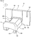
- FIG. 4 is a perspective view of the winding frame 10. Although the winding frames 10 are provided at both ends N1, N2 in the axial direction Z of the core 40, FIG. 4 shows the winding frame 10 at one end N1.
- the winding frame 10 is molded with a resin material such as polybutylene terephthalate (PBT) or polyphenylene sulfide (PPS), to which a filler such as a glass fiber is added.
- PBT polybutylene terephthalate
- PPS polyphenylene sulfide
- the winding frame 10 is composed of a first flange 12 provided on the yoke portion 42 side of the core 40, a second flange 13 provided on the end portion 43 side, and a trunk portion 11 connecting both flanges.
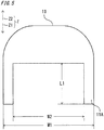
- the trunk portion 11 has a shape shown by a sectional view in FIG. 5 so that the trunk portion 11 can be mounted striding over the tooth portion 41 of the core 40.
- FIG. 4 shows only the winding frame 10 fitted on one end N1 side, of the two winding frames 10 fitted to both ends N1, N2 in the axial direction Z of the core 40.
- a direction toward the center in the axial direction Z of the core from both ends N1, N2 in the axial direction Z of the core is referred to as "center-side direction Z1”
- a direction opposite to the center-side direction Z1 is referred to as "separating direction Z2”.
- the center-side direction Z1 and the separating direction Z2 do not indicate absolute directions, but are defined with the center in the axial direction Z of the core 40 as a reference.
- a trunk portion width W1 is the same as the tooth portion width WT1 of the core 40 shown in FIG. 3
- a stride width W2 is set to a mountable dimension with respect to the tooth portion width WT2 at the part where the step portion is present.
- a length L1 of a striding leg 11E corresponds to the step length LT1 of the core 40 shown in FIG. 3 .
- the first flange 12 shown in FIG. 4 has grooves 12E through which the winding start wire and the winding end wire of the coil 30 are introduced.
- the second flange 13 has thin portions 13A extending in the axial direction Z so as to stride over the end portion 43 of the core 40, and projections 13B formed with gaps from the thin portions 13A.
- the projections 13B are formed in shapes elongated in the axial direction Z and extend in the center-side direction Z1. As the gap between the thin portion 13A and the projection 13B, a slit 13C having a predetermined depth dimension is formed, and a second surface 20B of the insulator 20 described later is inserted into the slit 13C.
- FIG. 6 shows the insulators 20.
- FIG. 6 shows a state in which a pair of insulators 20 are provided to the core 40 which is not shown.
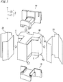
- FIG. 7 schematically shows a state before a pair of winding frames 10 and a pair of insulators 20 are attached to the core 40.
- a film material such as polyethylene terephthalate (PET) or polyethylene naphthalate (PEN) is used.
- a first surface 20A has an axial-direction length LF1 which is almost equal to the core length LC, and is attached to the tooth portion side surface 41B of the core 40 and the thin portion 11A of the winding frame 10.
- the second surface 20B has the same axial-direction length LF1 as the first surface 20A, and is attached to the end portion 43 of the core 40 and the slit 13C between the thin portion 13A and the projection 13B of the winding frame 10.
- a third surface 20C connected to the first surface 20A has, in an area other than an extension surface 20D, the same axial-direction length LF1 as the first surface 20A.
- the extension surface 20D connected to the third surface 20C has an axial-direction length LF3.
- An extension length LF2 is set to be equal to or greater than an insulation creeping distance determined by law and drive voltage of the rotary electric machine to which the magnetic pole 50 is applied.
- the insulation creeping distance is a distance from, of the end part in the axial direction Z of the yoke portion 42, an end E that is inward in the radial direction and outward in the circumferential direction, to a winding mounted on the insulator 20.
- the insulation creeping distance is ensured by the extension length LF2
- the insulation creeping distance is ensured by a predetermined width WF2 of the extension surface 20D.
- UL standard which is a product safety standard formulated by Underwriters Laboratories (abbreviation: UL) in North America
- UL984 hermetic refrigerant motor compressor
- a spatial distance of 3.2 mm and an insulation creeping distance of 4.8 mm are set as the minimum insulation distances at electric motor rating of 151 V to 300 V.
- the predetermined width WF2 is also set to a dimension equal to or greater than the extension length LF2.
- a fourth surface 20E connected to the extension surface 20D also has the axial-direction length LF3.
- a folded portion 20H at the boundary between the extension surface 20D and the fourth surface 20E is formed at a location corresponding to the position of a yoke end surface 42C shown in FIG. 2 .
- the third surface 20C and the extension surface 20D are to be attached to the thin portion 12A of the first flange 12, and the second surface 20B and the fourth surface 20E serve to cover the surface of the coil 30.
- the surfaces of the insulator 20 after the magnetic pole 50 is formed have been folded at the respective connection portions.
- the second surface 20B of the insulator 20 described above is inserted into the slit 13C of each winding frame 10, whereby the insulator 20 is held integrally with the core 40.
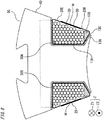
- FIG. 8 is a sectional view of the magnetic pole 50 manufactured by winding the coil 30 after the winding frames 10 and the insulators 20 are attached to the core 40 described above.
- the second surface 20B and the fourth surface 20E of each insulator 20 are folded so as to cover the coil 30, and thus increase insulation between the adjacent magnetic poles 50 when the stator 100 is formed.
- the coil 30 may be covered by one of the second surface 20B and the fourth surface 20E.
- dummy coils 30A, 30B serving to shape the coil 30 are provided on the first flange 12 side of the winding frame 10.
- the dummy coils 30A, 30B are provided, on the winding frame, at positions near the radially outer end of the tooth portion 41 and in contact with the conductive wire located closest to the core 40 among the conductive wires forming the coil.
- each sheet-like insulator 20 is arranged in a space M adjacent in the circumferential direction to the tooth portion 41. This space M may be referred to as "slot M".
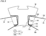
- FIG. 9 to FIG. 12 show sectional views of the core 40 crossing the axial direction Z, and therefore, of the parts constituting the winding frame 10, only parts needed for description are shown, and the insulators 20 in these drawings are shown in a state before the folded portions 20H shown in FIG. 6 are formed.
- each insulator 20 When each insulator 20 is attached to the core 40, the insulator 20 is held with the second surface 20B inserted into the slit 13C of the winding frame 10, but as shown in FIG. 9 , on the yoke portion 42 side of the core 40, the insulator 20 floats from the core 40. Therefore, as shown in FIG. 10 , using an insulator holder 60 which is a dedicated tool, the boundary part between the first surface 20A and the third surface 20C of the insulator 20 is held so as to be in close contact with the core 40.
- each insulator 20 is held so as to be deformed to bend toward the yoke portion 42 side.
- the insulator 20 can be kept in close contact with the core 40 by the end holder 61, and in this state, winding work for the coil 30 is performed.
- the spindle winding machine which rotates a work is used, and at this time, the end holders 61 can rotate together with the core 40 from the start of winding until the end of winding.
- the insulator holders 60 may be mounted to a work conveyance hand provided in the winding machine, for example.
- the spindle winding machine has been shown as an example of the winding machine, but in the case of using a connection core such as a poki-poki core or a joint-lap core, it is also possible to perform winding by a flyer winding machine, using the same configuration of the winding frames and the insulators as in the present Embodiment 1.
- a winding process applicable to Embodiment 1 of the present invention is not limited to the above-described method. It is also possible to perform winding using a conventional winding machine without the insulator holders 60 and the end holders 61. For example, control may be performed such that, after the core 40, the winding frames 10, and the sheet-like insulators 20 that have not been wound yet are mounted to the winding machine, the first one turn is wound in a state in which the sheet-like insulators 20 are floating from the core 40.
- the first one turn is wound so that the coil 30 does not interfere with the sheet-like insulators 20.
- the sheet-like insulators 20 come into close contact with the side surfaces of the tooth portion 41 of the core 40, and therefore, after that, it is possible to progress the winding work without trouble, while performing slight correction for the control.
- the magnetic poles 50 form at least a part of the stator 100 of the rotary electric machine and are arranged in an annular shape, and each magnetic pole 50 includes the core 40, the winding frames 10, and the sheet-like insulators 20.
- the core 40 includes the yoke portion 42, the tooth portion 41, and the end portion 43.
- the tooth portion 41 is formed to project from the yoke portion 42 in the radially inward direction, i.e., the direction toward the rotation axis of the rotary electric machine.
- the end portions 43 are arranged on the radially inner side of the tooth portion 41, and extend in the circumferential direction in which the magnetic poles 50 are arranged, from the radially inner ends of the tooth portions 41.
- the winding frames 10 are fitted to both ends N1, N2 of the core 40 in the axial direction Z parallel to the rotation axis, and have the thin portions 11A, 12A, 13A and the projections 13B.
- the thin portions 11A, 12A, 13A are each in contact with the surface of the core 40 that faces the space M adjacent in the circumferential direction to the tooth portion 41.
- Each projection 13B is formed with the gap 13C from the space M side surface of the thin portion 13A, in the space M, and extends in the center-side direction Z1 toward the center in the axial direction Z of the core 40.
- Each sheet-like insulator 20 makes insulation between the core 40 and the coil 30 wound around the tooth portion 41 and is arranged in the space M, and a part of the sheet-like insulator 20 is arranged in the gap 13C.
- each sheet-like insulator 20 is arranged in the gap 13C between the thin portion 13A and the projection 13B. Therefore, in a state in which the winding frames 10 and the sheet-like insulators 20 are arranged on the core 40 and the coil 30 has not been wound yet, the sheet-like insulators 20 can be fixed to the core 40 and the winding frames 10. Therefore, it is possible to omit a process of adhering or joining the sheet-like insulators 20 to the winding frames 10, and thus the magnetic pole can be manufactured easily and efficiently.
- each winding frame 10 has the trunk portion 11, the first flange 12, and the second flange 13.
- the trunk portion 11 is fitted to the tooth portion 41.
- the first flange 12 is formed, near the radially outer end of the tooth portion 41 opposite to the radially inner side, so as to extend from the trunk portion 11, in the separating direction opposite to the center-side direction Z1, and toward both sides in the circumferential direction.
- the second flange 13 is formed, near the radially inner end of the tooth portion 41, so as to extend from the trunk portion 11 in the separating direction and toward both sides in the circumferential direction.
- each winding frame 10 has the first flange 12 and the second flange 13. Therefore, when the coil 30 is wound around the tooth portion 41 and the winding frames 10 fitted to the core 40, the wound coil 30 can be prevented from being displaced in the radial direction.
- a part in contact with the thin portions 11A, 12A, 13A is recessed in a direction away from the space M by an amount corresponding to the thickness of the thin portions 11A, 12A, 13A as compared to the rest of the surface part.
- a part in contact with the thin portions 11A, 12A, 13A is recessed from the space M adjacent in the circumferential direction to the tooth portion 41, by an amount corresponding to the thickness of the thin portions, as compared to the rest of the surface part.
- the rest of the surface of the core 40, and the surfaces of the thin portions 11A, 12A, 13A of the winding frame 10 that face the space M are formed with no step therebetween in the axial direction Z. Therefore, when the sheet-like insulator 20 is inserted into the gap 13C between the thin portion 13A and the projection 13B of the winding frame 10, the insertion can be smoothly performed without being hampered.
- each winding frame 10 further has the guiding projections 30A, 30B.
- the guiding projections 30A, 30B are formed, on the winding frame 10, at positions that are near the radially outer end of the tooth portion 41 opposite to the radially inner side and that are in contact with the conductive wire located closest to the core 40 among the conductive wires forming the coil 30, and the guiding projections 30A, 30B position the conductive wire forming the coil 30.
- the guiding projections 30A, 30B position the conductive wire of the coil 30 at the position closest to the core 40.
- the winding work can be facilitated.
- each sheet-like insulator 20 covers the coil 30 such that, of the coil 30 wound around the tooth portion 41, a part adjacent in the circumferential direction to the tooth portion 41 is covered from four sides of: a side close to the tooth portion 41 in the circumferential direction; a side far from the tooth portion 41 in the circumferential direction; a radially inner side; and a radially outer side opposite to the radially inner side.
- each sheet-like insulator 20 covers the coil 30 such that, of the coil 30, a part adjacent to the tooth portion 41 is covered from four sides. Therefore, the sheet-like insulators 20 can make insulation not only between the core 40 and the coil 30 in the magnetic pole 50, but also between the coil 30 and a coil of another magnetic pole adjacent in the circumferential direction to the coil 30.
- the stator 100 includes the magnetic poles 50 and forms a part of the rotary electric machine.
- the sheet-like insulator 20 can be fixed to the core 40 and the winding frames 10. Therefore, it is possible to omit a process of adhering or joining the sheet-like insulators 20 to the winding frames 10, and thus the stator can be manufactured easily and efficiently.
- Embodiment 2 In the description in Embodiment 2 and later, some of parts corresponding to matters that have been already described in Embodiment 1 will not be described. In the case where only a part of a configuration is described, the other part of the configuration is the same as in Embodiment 1.
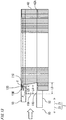
- FIG. 13 is a sectional projection view showing a state in which one winding frame 10 is attached to the core 40.
- a length L5 of the projection 13B formed at the second flange 13 of the winding frame 10 is shorter than a length L4 of the thin portion 11A of the trunk portion 11.
- a difference L4 - L5 therebetween is, for example, 2 mm to 5 mm.
- a chamfer 13D is formed at an end part of the projection 13B that is opposed to the thin portions 11A, 13A.
- the thin portion 11A has a taper 11C formed from the first flange 12 having a length L3 toward the second flange 13 having a length L4, and a step 11D is formed at a part that is on the end side of the thin portions 11A, 12A, 13A and on the core 40 side.
- the width dimension of the slit 13C shown in FIG. 4 in Embodiment 1 is set at 0.3 mm to 0.4 mm.
- the taper 11C is a sloped end formed on the thin portion 11A, and is sloped with respect to a line perpendicular to the axial direction Z in a plane parallel to the thin portion 11A.
- the taper 11C may be referred to as "sloped end 11C". Of the sloped end 11C, an end part positioned closest to the separating direction Z2 side is referred to as "shortest end T". Of the end part of the thin portion 11A of the trunk portion 11, the shortest end T is at the shortest distance from the end in the separating direction Z2 of the trunk portion 11. In the axial direction Z, the shortest end T is positioned closer to the center-side direction Z1 side as compared to a projection end portion P which is closest to the center-side direction Z1 side, of the projection 13B.
- FIG. 13 is a plan view of the insulator 20 to be used in the next step.
- the insulator 20 is the same as shown in FIG. 6 in Embodiment 1, and dotted lines indicate folding positions.
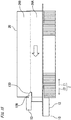
- FIG. 15 while the insulator 20 is in close contact with the core 40, the insulator 20 is slid in the axial direction Z from right to left in the drawing and thus inserted into the slit 13C of the winding frame 10.
- the length of the projection 13B is shorter than the length of the thin portion 11A. Therefore, when the sheet-like insulator 20 is inserted while being pressed against the thin portion 11A, the thin portion 11A serves as a guide for insertion of the sheet-like insulator 20, and thus insertion of the sheet-like insulator 20 is facilitated. Similarly, at the same time, since the chamfer 13D is formed at the end of the projection 13B, this serves as a guide when the sheet-like insulator 20 floats from the thin portion 11A, and thus insertion of the insulator 20 is further facilitated.
- the other winding frame 10 is mounted to the core 40 while the thin portion 11A is inserted between the tooth step portion 41A of the core 40 and the insulator 20, from the right side in the drawing. At this time, the insertion is performed so that the insulator 20 is located in the slit 13C. Thereafter, winding is performed by a winding machine to form the coil 30, whereby the magnetic pole 50 is obtained. By employing such a winding process, it is possible to obtain the magnetic pole 50 having increased insulation reliability while reducing the cost for manufacturing.
- the length of the projection 13B is shorter than those of the thin portions 11A, 12A, 13A and the chamfer 13D is formed, it is possible to slide the insulator 20 while the insulator 20 is placed on the thin portion 11A, and thus the thin portions 11A, 12A, 13A serve as guides for the insulator 20.
- the chamfer 13D is formed on the projection 13B, the chamfer 13D serves as a guide to facilitate insertion of the insulator 20.
- the taper 11C is formed from the first flange 12 toward the second flange 13.
- the thin portion 11A is formed such that the length on the first flange 12 side is longer than that on the second flange 13 side, and thus the end of the thin portion 11A is shaped as the taper 11C, which serves as a guide when the winding frame 10 is mounted from the yoke portion 42 side of the core 40, thereby facilitating the mounting.
- the step 11D is formed, the winding frame 10 is downsized by an amount corresponding to the step, the mounting is facilitated, and workability at the time of mounting the winding frame 10 to the core 40 is improved.
- the thin portion 11A may be formed in a taper shape such that the thickness decreases toward the end, and also in this case, the same effect is obtained.
- the chamfer shape at the end of the projection 13B is not limited. The same effect is obtained as long as the width of the slit 13C in which the insulator 20 is located is wider at the end of the projection 13B and narrower on the base side thereof.
- the thin portion 11A has the sloped end 11C.
- the sloped end 11C is formed on at least a part of the thin portion 11A, and is sloped with respect to a line perpendicular to the axial direction Z in a plane parallel to the surface of the core 40 that faces the space M.
- an end positioned closest to the center-side direction side connects to the sloped end 11C.
- the sloped end 11C is formed on the thin portion 11A and the end of the thin portion 11A that is positioned closest to the center-side direction Z1 side connects to the sloped end 11C, the sloped end 11C can guide the core 40 when the winding frame 10 is fitted to the core 40. Thus, work for fitting the winding frame 10 to the core 40 can be facilitated.
- the shortest end T of the thin portion 11A is positioned closer to the center-side direction Z1 side than the projection end portion P of the projection 13B.
- the shortest end T is positioned closest to the separating direction side opposite to the center-side direction Z1 side.
- the projection end portion P is positioned closest to the center-side direction Z1 side.
- the shortest end T of the thin portion 11A is positioned closer to the center-side direction Z1 side than the projection end portion P of the projection 13B.
- the end of the sheet-like insulator 20 inserted into the gap 13C between the thin portion 11A and the projection 13B can be located in contact with the thin portion 11A, on the winding frame 10 side with respect to the boundary between the thin portion 11A and the core 40. Therefore, the sheet-like insulator 20 can be smoothly inserted without being hampered.
- the chamfer 13D is formed at the projection end portion P positioned closest to the center-side direction Z1 side, of the projection 13B.
- the chamfer 13D is sloped with respect to a line perpendicular to the axial direction Z in a plane parallel to the surface of the core 40 that the projection 13B faces.
- the chamfer 13D is formed at the projection end portion P. Therefore, when the sheet-like insulator 20 is inserted into the gap 13C between the thin portion 11A and the projection 13B, the projection end portion P is less likely to hamper the insertion.
- the winding frame 10 and the insulator 20 in Embodiment 3 will be described with reference to FIG. 17 to FIG. 19 .
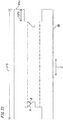
- the winding frame 10 has, at the thin portion 11A, a taper 11C which is formed from a position separate by a predetermined dimension K from the first flange 12 side, and cutouts 20F are formed in the first surface 20A of the insulator 20.
- a width S and a depth L of each cutout 20F may be set to such dimensions as to allow the projection 13B of the winding frame 10 to pass therethrough, and the position thereof may be at any position in the first surface 20A of the insulator 20.
- the start point of the taper 11C of the thin portion 11A of the trunk portion 11 is set at a position separate by the predetermined dimension K from the first flange 12.
- each cutout 20F is constant in the axial direction Z from around the bottom that defines the cutout 20F from the center-side direction Z1 side, to around the end in the separating direction Z2 of the sheet-like insulator 20.
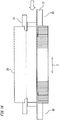
- FIG. 17 a pair of winding frames 10 are mounted to the core 40. From this state, the insulator 20 having the cutouts 20F shown in FIG. 18 is moved so that, as shown in FIG. 19 , the projections 13B pass through the cutouts 20F, and then the position of the insulator 20 is shifted in the radial direction, i.e., from the second flange 13 side to the first flange 12 side in FIG. 19 , whereby mounting of the winding frames 10 and the insulator 20 to the core 40 is completed.
- each cutout 20F may be on a side close to the first flange 12 so as to have an advantage in terms of insulation creeping distance, or may be near the center of the first surface 20A from the perspective of mounting workability.
- the sheet-like insulator 20 has, at both ends in the axial direction Z, cutouts 20F recessed in the center-side direction Z1.
- the position in the axial direction Z of the bottom that defines each cutout 20F from the center-side direction Z1 side is closer to the center-side direction Z1 side than the projection end portion P which is positioned closest to the center-side direction Z1 side, of the projection 13B.
- the width S of each cutout 20F in a direction perpendicular to the axial direction Z is set to be greater than the minimum outer diameter of the projection 13B in a plane perpendicular to the axial direction Z.
- each cutout 20F formed in the sheet-like insulator 20 is positioned closer to the center-side direction Z1 side than the projection end portion P, and the width S of the cutout 20F is greater than the minimum outer diameter of the projection 13B. Therefore, it is possible to pass the projection 13B through each cutout 20F by moving the sheet-like insulator 20 in a direction perpendicular to the axial direction Z.
- FIG. 20 shows an insulator 20 in Embodiment 4.
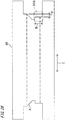
- the insulator 20 has cuts 20G at both ends in the axial direction Z (longitudinal direction) at the boundary between the first surface 20A and the third surface 20C.
- a width B and a depth H of each cut 20G may be set to such dimensions as to accommodate two wires of the conductor of the coil 30.
- the cutouts 20G may be provided to the insulator 20 shown in FIG. 14 to FIG. 16 .
- the dummy coils 30A, 30B are shaped so as not to extend into the slot M which is the space M surrounded by the tooth portion side surface 41B, the yoke portion side surface 42B, and the end portion 43 of the core 40.
- a dummy coil 30C and a dummy coil 30D are formed so as to extend into the slot M, and slits 30S are formed between the dummy coils and the thin portions 11A, 12A so as to allow the insulator 20 to be located in the slits 30S.
- FIG. 22 shows a sectional view of a magnetic pole 50 in the present embodiment 5.
- the insulator 20 since the insulator 20 is located in the slits 30S, the insulator 20 can be held at a total of four locations including the slits 13C, whereby winding work is facilitated.
- FIG. 23 is a plan view of the sheet-like insulator 20 in Embodiment 6 of the present invention.
- FIG. 24 illustrates operation at the time of attaching the sheet-like insulator 20 to the winding frames 10 in Embodiment 6 of the present invention.
- the present Embodiment 6 is similar to Embodiment 3.
- Embodiment 6 is different from Embodiment 3 in the shape of the cutouts 20F formed in the first surface 20A of the sheet-like insulator 20. As shown in FIG. 24 , a side A is formed to form an angle ⁇ with respect to the extension direction of the projection 13B, i.e., the stacking direction Z of the core 40.
- the sheet-like insulator 20 when the sheet-like insulator 20 is mounted to the core 40 to which the winding frames 10 are mounted at both ends N1, N2 in the axial direction Z, since the side A passing through the gap 13C formed between the projection 13B and the thin portion 11A forms the angle ⁇ with respect to the extension direction of the projection 13B, the side A can pass smoothly without being caught on the projection 13B. As a result, the time for mounting the sheet-like insulator 20 can be shortened and the manufacturing cost can be reduced.
- FIG. 23 and FIG. 24 show an example in which the angle ⁇ between the stacking direction Z of the core 40 and the side A is 45°. However, as the angle ⁇ decreases, it usually becomes more difficult to ensure the insulation creeping distance.
- FIG. 25 is a plan view of the sheet-like insulator 20 in a modification of Embodiment 6 of the present invention.
- the side A may be formed in a curve shape, and also in this case, the same effect as described above is obtained.
- an extension surface 20J similar to the fourth surface 20E in Embodiment 1 is provided to the second surface 20B of the sheet-like insulator 20.
- the extension length in the axial direction Z of the extension surface 20J is an axial-direction length LF2 which is the same as that of the fourth surface 20E in Embodiment 1
- the entire axial-direction length of the second surface 20B provided with the extension surface 20J is an axial-direction length LF3 which is the same as that of the fourth surface 20E in Embodiment 1.
- the extension surface 20J provided to the second surface 20B and the fourth surface 20E are folded to overlap each other, thereby obtaining an effect of improving reliability of insulation between the coils of the adjacent magnetic poles.
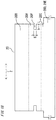
- At least one of both side parts defining each cutout 20F in a direction perpendicular to the axial direction Z is sloped with respect to the axial direction Z.
- the width of the cutout 20F near the end in the axial direction Z of the sheet-like insulator 20 is set to be wider than that near the bottom of the cutout 20F.
- each cutout 20F is sloped and the width of the cutout 20F near the end is set to be wider than that near the bottom thereof. Therefore, in insertion of the sheet-like insulator 20 into the gap 13C between the thin portion 13A and the projection 13B, the sheet-like insulator 20 is moved in a direction perpendicular to the axial direction Z and inserted such that the above sloped part is on the rear side, whereby the projection 13B can be easily passed through each cutout 20F.
- arrangement of the sheet-like insulator 20 to the core 40 and the winding frames 10 is facilitated and the magnetic pole can be efficiently manufactured.
- FIG. 26 is a plan view of a sheet-like insulator 20 in Embodiment 7 of the present invention.
- Embodiment 7 is similar to Embodiment 4 and Embodiment 6, and the sheet-like insulator 20 has cuts 20G having an increased width B without changing the depth H.
- each cut 20G is expanded up to the part defining the cutout 20F, thus forming a step from the bottom of the cutout 20F. Also in the case of such a shape, the same effect as in Embodiment 4 and Embodiment 6 is obtained.
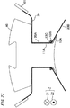
- FIG. 27 is a sectional view of a magnetic pole 50 in Embodiment 8 of the present invention.
- each projection 13B has a columnar shape, and is formed on the trunk portion 11, at a position near the thin portion 11A of the trunk portion 11.
- Each sheet-like insulator 20 is held by being located in the gap 13C between the projection 13B and the thin portion 11A of the trunk portion 11. Even by employing such a structure, the sheet-like insulators 20 can be held, and insulation of the entire magnetic pole 50 by the sheet-like insulators 20 and productivity of the magnetic pole 50 are improved.
- each projection 13B has a columnar shape, but is not limited thereto.
- Each projection 13B may be provided at such a position as to stride over both the thin portion 11A of the trunk portion 11 and the thin portion 13A of the second flange 13, and also in this case, the same effect is obtained.
- a stator obtained by arranging a plurality of the magnetic poles 50 according to embodiments 1 to 8 of the present invention in an annular shape, welding and fixing the cores 40, and performing necessary wire connection for the coils 30 has increased insulation property and increased productivity as compared to the conventional stator.
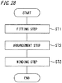
- FIG. 28 is a flowchart showing a method for manufacturing a magnetic pole according to Embodiment 9 of the present invention.
- the magnetic pole described in any one of embodiments 1 to 8 is manufactured.
- the method for manufacturing the magnetic pole includes a fitting step, an arrangement step, and a winding step. When this process is started, in the fitting step of step ST1, the winding frames 10 are fitted to both ends N1, N2 in the axial direction Z of the core 40.
- step ST2 a part of the end of each sheet-like insulator 20 is arranged in the gap 13C between the thin portion 13A and the projection 13B.
- step ST3 the coil 30 is wound around the tooth portion 41 with the winding frames 10 and the sheet-like insulators 20 provided therebetween. Then, the process is finished.
- the rotary electric machine including the stator according to the present invention is applicable as a rotary electric machine provided to an air-conditioner compressor, or a rotary electric machine such as an industrial servomotor or an in-vehicle motor.
- the core 40 is composed of the yoke portion 42, the tooth portion 41, and the end portion 43 extending in an arc shape from the tooth portion 41; each winding frame 10 is composed of the first flange 12 provided to the yoke portion 42 and having the thin portion 12A, the second flange 13 opposed to the first flange 12 and having the thin portion 13A and the projection 13B extending in the axial direction Z from around the end portion 43, and the trunk portion 11 connecting the first flange 12 and the second flange 13 and having the thin portion 11A formed so as to stride over the tooth portion 41; the winding frames 10 are provided at both ends N1, N2 in the axial direction Z of the core 40; each insulator 20 is composed of the first surface 20A to be mounted to the side surface of the tooth portion 41 and the thin portion 11A of the trunk portion 11, the second surface 20B which is connected to the first surface 20A and is
- each insulator 20 is inserted into the slit 13C formed by the thin portion 11A of the winding frame 10 and the dummy coil 30A, 30B provided on the first flange 12 side of the winding frame 10, whereby the insulator 20 is fixed along the side surface of the tooth portion 41 of the core 40.
- the axial-direction lengths of the thin portion 12A of the first flange 12, the thin portion 11A of the trunk portion 11, and the thin portion 13A near the end portion 43 are equal to or greater than the insulation distance prescribed by laws or standards, and the predetermined length of the insulator 20 is also equal to or greater than the insulation distance.
- the length of the thin portion 12A on the first flange 12 side is greater than the length of the thin portion 13A on the second flange 13 side, and the end of the thin portion 11A of the trunk portion 11 has a taper shape or partially has a taper shape.
- the axial-direction length of the projection 13B is smaller than the axial-direction length of the thin portion 11A of the winding frame 10.
- the chamfer 13D is formed at the end in the axial direction Z of the projection 13B.
- the first surface 20A of each insulator 20 has, on both ends in the axial direction Z, the cutouts 20F which allow the projections 13B to pass therethrough.
- each insulator 20 has cuts 20G having a width corresponding to two wires of the conductor of the coil 30, at both ends in the axial direction Z at the boundary between the first surface 20A and the third surface 20C.
- a stator is formed by arranging a plurality of the magnetic poles 50 in an annular shape.
- a method for manufacturing the magnetic pole includes the following steps.
- step 1 a pair of winding frames 10 are attached to the core 40.
- step 2 the second surface 20B of each insulator 20 is inserted into the slit 13C of the winding frame 10.
- step 3 the boundary part between the first surface 20A and the third surface 20C of each insulator 20 is brought into close contact with the core 40, using the insulator holder 60 which is a dedicated tool.
- step 4 the fourth surface 20E of each insulator 20 is deformed to bend toward the yoke portion 42 side of the core 40, using the end holder 61 which is a dedicated tool.
- step 5 the insulator holders 60 are removed.
- step 6 a conductor is wound by a winding machine, to form the coil 30.
- each insulator 20 is folded so that the fourth surface 20E thereof covers the surface of the coil 30 or the second surface 20B and the fourth surface 20E thereof cover the surface of the coil 30.
- Another method for manufacturing the magnetic pole includes the following steps.
- step 1 one winding frame 10 is mounted to one end in the axial direction Z of the core 40.
- each insulator 20 is slid in the axial direction Z while being in contact with the core 40, and thus the second surface 20B of the insulator 20 is inserted into the slit 13C of the winding frame 10.
- step 3 the other winding frame 10 to be mounted to the other end of the core 40 is attached so that the second surface 20B of the insulator 20 is inserted into the slit 13C of the other winding frame 10.
- step 4 the boundary part between the first surface 20A and the third surface 20C of each insulator 20 is brought into close contact with the core 40, using the insulator holder 60 which is a dedicated tool.
- step 5 the fourth surface 20E of each insulator 20 is deformed to bend toward the yoke portion 42 side of the core 40, using the end holder 61 which is a dedicated tool.
- step 6 the insulator holders 60 are removed.
- step 7 a conductor is wound by a winding machine, to form the coil 30.
- each insulator 20 is folded so that the fourth surface 20E thereof covers the surface of the coil 30 or the second surface 20B and the fourth surface 20E thereof cover the surface of the coil 30.
Landscapes
- Engineering & Computer Science (AREA)
- Power Engineering (AREA)
- Manufacturing & Machinery (AREA)
- Insulation, Fastening Of Motor, Generator Windings (AREA)
- Iron Core Of Rotating Electric Machines (AREA)
- Manufacture Of Motors, Generators (AREA)
Abstract
Description
- The present invention relates to a magnetic pole for a rotary electric machine, a method for manufacturing a magnetic pole, and a stator, and in particular, relates to a magnetic pole having increased efficiency and increased insulation property at low cost.
- In a conventional stator core for a rotary electric machine, a configuration is disclosed in which a pair of step portions extending inward from both end sides in the thickness direction and having predetermined length and level difference are formed at a part of any of surfaces on the inner side of a protruding portion of a magnetic pole tooth portion, the magnetic pole tooth portion, and the inner side of a yoke portion, an insulating winding frame is fitted to each step portion with the thickness-direction length thereof matched with the length of the step portion, and on both side areas between the pair of insulating winding frames, a pair of insulating films are provided of which both ends are applied to the surfaces of the pair of insulating winding frames and which are stretched between the pair of insulating winding frames (see, for example, Patent Document 1).
- Patent Document 1: Japanese Laid-Open Patent Application Publication
JP 2003-111 329 A - However, in the configuration disclosed in
Patent Document 1, both ends of the insulating films are applied to a trunk portion and both flange portions of each insulating winding frame by ultrasonic welding, and therefore a device for welding and a welding step are needed and equipment investment and increase in manufacturing cost are inevitable. - In the case where management of a welding condition is insufficient and the welding condition is too strong, a hole is made in the insulating film, and conversely, if the welding condition is weak, the insulating film is not welded or other troubles occur. Thus, a problem can occur with the insulation reliability of the magnetic pole.
- The present invention has been made to solve the above problems, and an object of the present invention is to provide a magnetic pole, a method for manufacturing a magnetic pole, and a stator that have a simple and highly-reliable insulation configuration and have stable insulation property.
- The present invention providesd a magnetic pole to form at least a part of a stator of a rotary electric machine by a plurality of the magnetic poles being arranged in an annular shape, the magnetic pole including:
- a core having an arc-shaped yoke portion forming a part of an outer circumferential portion of the stator,
- a tooth portion projecting from the yoke portion toward a central axis of the stator, and an end portion extending in a circumferential direction of the stator from an end on a central axis side of the tooth portion; winding frames provided to both ends, in a direction along the central axis, of the core, the winding frames having thin portions extending in the direction along the central axis, and projections projecting in the direction; and
- sheet-like insulators provided on both sides in the circumferential direction of the tooth portion, wherein a part of each insulator is held by being sandwiched between the projection and the thin portion provided to each winding frame.
- Another aspect of the present invention is a stator including the magnetic poles and forming a part of the rotary electric machine.
- Still another aspect of the present invention is a method for manufacturing the magnetic pole, the method including: a fitting step of fitting the winding frames to both ends in the central axis direction of the core; an arrangement step of arranging a part of an end in the central axis direction of each sheet-like insulator, into a gap between each thin portion and each projection; and a winding step of winding a coil around the tooth portion with the winding frames and the sheet-like insulators provided therebetween.
- According to the present invention, owing to the configuration and method as described above, it becomes possible to provide, at low cost, a magnetic pole that enables simplification of attachment of insulators and winding frames to a core and prevents the insulators from being damaged by an attachment work, thereby having increased insulation property.
-
- FIG. 1
- is a sectional view of a stator of a rotary electric machine in
Embodiment 1. - FIG. 2
- is a perspective view of a core in
Embodiment 1. - FIG. 3
- is a sectional view of the core in
Embodiment 1. - FIG. 4
- is a perspective view of a winding frame in Embodiment 1.
- FIG. 5
- is a sectional view of a trunk portion in Embodiment 1.
- FIG. 6
- is a perspective view of an insulator in
Embodiment 1. - FIG. 7
- is a perspective view showing attachment of the winding frames and the insulators to the core in
Embodiment 1. - FIG. 8
- is a sectional view of a magnetic pole in
Embodiment 1. - FIG. 9
- illustrates a manufacturing process for the magnetic pole in
Embodiment 1. - FIG. 10
- illustrates the manufacturing process for the magnetic pole in
Embodiment 1. - FIG. 11
- illustrates the manufacturing process for the magnetic pole in
Embodiment 1. - FIG. 12
- illustrates the manufacturing process for the magnetic pole in
Embodiment 1. - FIG. 13
- shows attachment of an insulator to a core in
Embodiment 2. - FIG. 14
- is a plan view showing the insulator in Embodiment 2.
- FIG. 15
- shows attachment of the insulator to the core in
Embodiment 2. - FIG. 16
- shows attachment of the insulator to the core in
Embodiment 2. - FIG. 17
- shows attachment of an insulator to a core in Embodiment 3.
- FIG. 18
- is a plan view showing the insulator in Embodiment 3.
- FIG. 19
- shows attachment of the insulator to the core in Embodiment 3.
- FIG. 20
- is a plan view showing an insulator in Embodiment 4.
- FIG. 21
- is a perspective view of a winding frame in Embodiment 5.
- FIG. 22
- is a sectional view of a magnetic pole in Embodiment 5.
- FIG. 23
- is a plan view of a sheet-like insulator in Embodiment 6.
- FIG. 24
- illustrates operation for attaching the sheet-like insulator to winding frames in Embodiment 6.
- FIG. 25
- is a plan view of a sheet-like insulator in a modification of Embodiment 6.
- FIG. 26
- is a plan view of a sheet-like insulator in
Embodiment 7. - FIG. 27
- is a sectional view of a magnetic pole in Embodiment 8.
- FIG. 28
- is a flowchart showing a method for manufacturing a magnetic pole according to Embodiment 9.
- Hereinafter,
Embodiment 1 of the present invention will be described with reference to the drawings.FIG. 1 is a sectional view of astator 100 of a rotary electric machine. InFIG. 1 , thestator 100 is assembled in an annular shape by connecting and arranging a plurality ofmagnetic poles 50 on a circle. Eachmagnetic pole 50 is composed of acore 40 and acoil 30 obtained by winding a conductor with a plurality of turns after attaching windingframes 10 andinsulators 20 to thecore 40. - The winding frames 10 have functions of electrically insulating the
core 40 and thecoil 30 from each other, allowing thecoil 30 to be wound at a predetermined position, and supporting a connection portion between the coil and a terminal and holding the insulators at predetermined positions. As described in detail inFIG. 2 , thecore 40 is composed of: an arc-shapedyoke portion 42 forming a part of the outer circumferential portion of thestator 100 of the rotary electric machine and joined to theadjacent cores 40; atooth portion 41 connected to theyoke portion 42 and projecting from theyoke portion 42 toward the central axis (rotation axis) of an armature of the rotary electric machine (not shown); and an arc-shapedend portion 43 opposed to the armature of the rotary electric machine (not shown). - A direction toward the rotation axis of the rotary electric machine is referred to as "radially inward direction", and a direction opposite to the radially inward direction, i.e., a direction away from the rotation axis is referred to as "radially outward direction". Each
core 40 is formed by stacking thin sheets that are stamped out. Here, the case where the stator of the rotary electric machine is formed by arranging a plurality of magnetic poles in an annular shape and the yoke portions have an arc shape is described. - However, the yoke portions are not limited to an arc shape. In the case where magnetic poles are arranged in a polygonal annular shape, each yoke portion may have substantially a straight shape. The end portions also have an arc shape so as to keep an equal distance from the cylindrical armature of the rotary electric machine. However, as long as necessary performance is obtained even if the distance from the armature of the rotary electric machine is not kept equal, the part facing the armature of the rotary electric machine may have substantially a straight shape.
- In the description, a direction parallel to the central axis of the rotary electric machine is referred to as an axial direction Z. Since the
core 40 is formed by being stacked in the axial direction Z, the axial direction Z may be referred to as "stacking direction Z" of thecore 40. The circumferential direction of the annular shape formed by the plurality of magnetic poles arranged around the axis is simply referred to as "circumferential direction". -
FIG. 2 is a perspective view of a part of thecore 40. As shown inFIG. 2 , thecore 40 has substantially a T shape and has a core length LC in the axial direction Z. At both ends N1, N2 in the axial direction Z of the core 40, atooth step portion 41A, ayoke step portion 42A, and anend step portion 43A are formed. - These step portions have the same shape, and
FIG. 3 shows a sectional view of thetooth portion 41 including thetooth step portion 41A as a representative. A tooth portion width WT2 at a part where thetooth step portion 41A is formed has a value obtained by subtracting step depths D1 on both sides from a tooth portion width WT1, and the step portion has a step length LT1 in the axial direction Z. -
Thin portions frame 10 described later are to be fitted to thetooth step portion 41A, theyoke step portion 42A, and theend step portion 43A of thecore 40. Since the step portions are provided at both ends N1, N2 in the axial direction Z of the core 40 as described above, thethin portions coil 30 is expanded, and thus it becomes possible to, for example, enlarge the wire diameter of the coil conductor and increase the number of winding turns. Further, when the stator is formed, the efficiency is increased. -
FIG. 4 is a perspective view of the windingframe 10. Although the windingframes 10 are provided at both ends N1, N2 in the axial direction Z of the core 40,FIG. 4 shows the windingframe 10 at one end N1. The windingframe 10 is molded with a resin material such as polybutylene terephthalate (PBT) or polyphenylene sulfide (PPS), to which a filler such as a glass fiber is added. - As shown in
FIG. 4 , the windingframe 10 is composed of afirst flange 12 provided on theyoke portion 42 side of the core 40, asecond flange 13 provided on theend portion 43 side, and atrunk portion 11 connecting both flanges. Thetrunk portion 11 has a shape shown by a sectional view inFIG. 5 so that thetrunk portion 11 can be mounted striding over thetooth portion 41 of thecore 40. -
FIG. 4 shows only the windingframe 10 fitted on one end N1 side, of the two windingframes 10 fitted to both ends N1, N2 in the axial direction Z of thecore 40. In the axial direction Z, a direction toward the center in the axial direction Z of the core from both ends N1, N2 in the axial direction Z of the core is referred to as "center-side direction Z1", and in the axial direction Z, a direction opposite to the center-side direction Z1 is referred to as "separating direction Z2". The center-side direction Z1 and the separating direction Z2 do not indicate absolute directions, but are defined with the center in the axial direction Z of the core 40 as a reference. - In
FIG. 5 , a trunk portion width W1 is the same as the tooth portion width WT1 of the core 40 shown inFIG. 3 , and a stride width W2 is set to a mountable dimension with respect to the tooth portion width WT2 at the part where the step portion is present. A length L1 of a striding leg 11E corresponds to the step length LT1 of the core 40 shown inFIG. 3 . - The
first flange 12 shown inFIG. 4 hasgrooves 12E through which the winding start wire and the winding end wire of thecoil 30 are introduced. Thesecond flange 13 hasthin portions 13A extending in the axial direction Z so as to stride over theend portion 43 of the core 40, andprojections 13B formed with gaps from thethin portions 13A. Theprojections 13B are formed in shapes elongated in the axial direction Z and extend in the center-side direction Z1. As the gap between thethin portion 13A and theprojection 13B, aslit 13C having a predetermined depth dimension is formed, and asecond surface 20B of theinsulator 20 described later is inserted into theslit 13C. -
FIG. 6 shows theinsulators 20.FIG. 6 shows a state in which a pair ofinsulators 20 are provided to the core 40 which is not shown.FIG. 7 schematically shows a state before a pair of windingframes 10 and a pair ofinsulators 20 are attached to thecore 40. For theinsulators 20, a film material such as polyethylene terephthalate (PET) or polyethylene naphthalate (PEN) is used. - As described later, the
insulators 20 are mounted to the windingframes 10, tooth portion side surfaces 41B and yoke portion side surfaces 42B of the core 40, and the like, and thereafter, thecoil 30 is wound. Afirst surface 20A has an axial-direction length LF1 which is almost equal to the core length LC, and is attached to the toothportion side surface 41B of thecore 40 and thethin portion 11A of the windingframe 10. - The
second surface 20B has the same axial-direction length LF1 as thefirst surface 20A, and is attached to theend portion 43 of thecore 40 and theslit 13C between thethin portion 13A and theprojection 13B of the windingframe 10. A third surface 20C connected to thefirst surface 20A has, in an area other than anextension surface 20D, the same axial-direction length LF1 as thefirst surface 20A. Theextension surface 20D connected to the third surface 20C has an axial-direction length LF3. - An extension length LF2 is set to be equal to or greater than an insulation creeping distance determined by law and drive voltage of the rotary electric machine to which the
magnetic pole 50 is applied. As used herein, the insulation creeping distance is a distance from, of the end part in the axial direction Z of theyoke portion 42, an end E that is inward in the radial direction and outward in the circumferential direction, to a winding mounted on theinsulator 20. In the present embodiment, in the axial direction Z, the insulation creeping distance is ensured by the extension length LF2, and in the circumferential direction, the insulation creeping distance is ensured by a predetermined width WF2 of theextension surface 20D. - For example, according to UL standard which is a product safety standard formulated by Underwriters Laboratories (abbreviation: UL) in North America, in UL984 (hermetic refrigerant motor compressor), a spatial distance of 3.2 mm and an insulation creeping distance of 4.8 mm are set as the minimum insulation distances at electric motor rating of 151 V to 300 V. By ensuring dimensions equal to or greater than the above values, it is possible to obtain the
magnetic pole 50 ensuring insulation reliability. - Other than this, setting may be made with reference to laws and regulations such as Electrical Appliances and Materials Safety Act in Japan or International Electrotechnical Commission in Europe. Similarly, the predetermined width WF2 is also set to a dimension equal to or greater than the extension length LF2. A
fourth surface 20E connected to theextension surface 20D also has the axial-direction length LF3. - As shown in
FIG. 6 , a foldedportion 20H at the boundary between theextension surface 20D and thefourth surface 20E is formed at a location corresponding to the position of a yoke end surface 42C shown inFIG. 2 . The third surface 20C and theextension surface 20D are to be attached to thethin portion 12A of thefirst flange 12, and thesecond surface 20B and thefourth surface 20E serve to cover the surface of thecoil 30. The surfaces of theinsulator 20 after themagnetic pole 50 is formed have been folded at the respective connection portions. - The
second surface 20B of theinsulator 20 described above is inserted into theslit 13C of each windingframe 10, whereby theinsulator 20 is held integrally with thecore 40. -
FIG. 8 is a sectional view of themagnetic pole 50 manufactured by winding thecoil 30 after the windingframes 10 and theinsulators 20 are attached to the core 40 described above. As shown inFIG. 8 , thesecond surface 20B and thefourth surface 20E of eachinsulator 20 are folded so as to cover thecoil 30, and thus increase insulation between the adjacentmagnetic poles 50 when thestator 100 is formed. However, depending on the level of the standard voltage, thecoil 30 may be covered by one of thesecond surface 20B and thefourth surface 20E. - In
FIG. 8 , when a conductor is wound around thecore 40 to form thecoil 30, dummy coils 30A, 30B serving to shape thecoil 30 are provided on thefirst flange 12 side of the windingframe 10. Thus, regular winding of thecoil 30 is facilitated. The dummy coils 30A, 30B are provided, on the winding frame, at positions near the radially outer end of thetooth portion 41 and in contact with the conductive wire located closest to thecore 40 among the conductive wires forming the coil. - In winding work for winding a conductive wire around the
tooth portion 41 to form the coil, the dummy coils 30A, 30B position and guide the first one turn of the conductive wire. The dummy coils 30A, 30B may be referred to as "guidingprojections FIG. 8 , each sheet-like insulator 20 is arranged in a space M adjacent in the circumferential direction to thetooth portion 41. This space M may be referred to as "slot M". - Next, a process of attaching the winding
frames 10 and theinsulators 20 to thecore 40 and then winding a conductor to form thecoil 30 and obtain themagnetic pole 50 inEmbodiment 1, in which a coil winding process is not shown in the drawings, will be described with reference toFIG. 9 to FIG. 12 . It is noted that, inFIG. 8 to FIG. 12 and inFIG. 22 described later, the upper side and the lower side of the core 40 are opposite to those inFIG. 13 to FIG. 20 described later, for convenience of description. However, the actual direction depends on the configuration of a winding machine. - For example, in the case of a spindle winding machine which rotates a work, the output shaft of the spindle motor is often set upward in the vertical direction, and accordingly, the
core 40 is arranged such that thetooth portion 41 is on the upper side and theyoke portion 42 is on the lower side.FIG. 9 to FIG. 12 show sectional views of the core 40 crossing the axial direction Z, and therefore, of the parts constituting the windingframe 10, only parts needed for description are shown, and theinsulators 20 in these drawings are shown in a state before the foldedportions 20H shown inFIG. 6 are formed. - When each
insulator 20 is attached to thecore 40, theinsulator 20 is held with thesecond surface 20B inserted into theslit 13C of the windingframe 10, but as shown inFIG. 9 , on theyoke portion 42 side of the core 40, theinsulator 20 floats from thecore 40. Therefore, as shown inFIG. 10 , using aninsulator holder 60 which is a dedicated tool, the boundary part between thefirst surface 20A and the third surface 20C of theinsulator 20 is held so as to be in close contact with thecore 40. - Subsequently, as shown in
FIG. 11 , using anend holder 61 which is a dedicated tool, an outermost part of thefourth surface 20E of eachinsulator 20 is held so as to be deformed to bend toward theyoke portion 42 side. Thereafter, as shown inFIG. 12 , even if theinsulator holder 60 is removed, theinsulator 20 can be kept in close contact with the core 40 by theend holder 61, and in this state, winding work for thecoil 30 is performed. By employing such a winding process, it is possible to obtain a magnetic pole having increased insulation reliability while reducing the cost for manufacturing. - As the winding machine, the spindle winding machine which rotates a work is used, and at this time, the
end holders 61 can rotate together with the core 40 from the start of winding until the end of winding. On the other hand, theinsulator holders 60 may be mounted to a work conveyance hand provided in the winding machine, for example. - The spindle winding machine has been shown as an example of the winding machine, but in the case of using a connection core such as a poki-poki core or a joint-lap core, it is also possible to perform winding by a flyer winding machine, using the same configuration of the winding frames and the insulators as in the
present Embodiment 1. - A winding process applicable to
Embodiment 1 of the present invention is not limited to the above-described method. It is also possible to perform winding using a conventional winding machine without theinsulator holders 60 and theend holders 61. For example, control may be performed such that, after thecore 40, the windingframes 10, and the sheet-like insulators 20 that have not been wound yet are mounted to the winding machine, the first one turn is wound in a state in which the sheet-like insulators 20 are floating from thecore 40. - In this control, the first one turn is wound so that the
coil 30 does not interfere with the sheet-like insulators 20. Once the first one turn is wound, the sheet-like insulators 20 come into close contact with the side surfaces of thetooth portion 41 of the core 40, and therefore, after that, it is possible to progress the winding work without trouble, while performing slight correction for the control. - As described above, according to the
present Embodiment 1, a process of welding theinsulator 20 as in the conventional case is not needed, and thus it is possible to obtain themagnetic pole 50 with increased insulation reliability at low cost. - According to
Embodiment 1 of the present invention, themagnetic poles 50 form at least a part of thestator 100 of the rotary electric machine and are arranged in an annular shape, and eachmagnetic pole 50 includes the core 40, the windingframes 10, and the sheet-like insulators 20. Thecore 40 includes theyoke portion 42, thetooth portion 41, and theend portion 43. Thetooth portion 41 is formed to project from theyoke portion 42 in the radially inward direction, i.e., the direction toward the rotation axis of the rotary electric machine. Theend portions 43 are arranged on the radially inner side of thetooth portion 41, and extend in the circumferential direction in which themagnetic poles 50 are arranged, from the radially inner ends of thetooth portions 41. - The winding frames 10 are fitted to both ends N1, N2 of the core 40 in the axial direction Z parallel to the rotation axis, and have the
thin portions projections 13B. Thethin portions tooth portion 41. Eachprojection 13B is formed with thegap 13C from the space M side surface of thethin portion 13A, in the space M, and extends in the center-side direction Z1 toward the center in the axial direction Z of thecore 40. Each sheet-like insulator 20 makes insulation between the core 40 and thecoil 30 wound around thetooth portion 41 and is arranged in the space M, and a part of the sheet-like insulator 20 is arranged in thegap 13C. - As described above, a part of each sheet-
like insulator 20 is arranged in thegap 13C between thethin portion 13A and theprojection 13B. Therefore, in a state in which the windingframes 10 and the sheet-like insulators 20 are arranged on thecore 40 and thecoil 30 has not been wound yet, the sheet-like insulators 20 can be fixed to thecore 40 and the winding frames 10. Therefore, it is possible to omit a process of adhering or joining the sheet-like insulators 20 to the windingframes 10, and thus the magnetic pole can be manufactured easily and efficiently. - In addition, according to
Embodiment 1, each windingframe 10 has thetrunk portion 11, thefirst flange 12, and thesecond flange 13. Thetrunk portion 11 is fitted to thetooth portion 41. Thefirst flange 12 is formed, near the radially outer end of thetooth portion 41 opposite to the radially inner side, so as to extend from thetrunk portion 11, in the separating direction opposite to the center-side direction Z1, and toward both sides in the circumferential direction. Thesecond flange 13 is formed, near the radially inner end of thetooth portion 41, so as to extend from thetrunk portion 11 in the separating direction and toward both sides in the circumferential direction. - As described above, each winding
frame 10 has thefirst flange 12 and thesecond flange 13. Therefore, when thecoil 30 is wound around thetooth portion 41 and the windingframes 10 fitted to thecore 40, thewound coil 30 can be prevented from being displaced in the radial direction. - In addition, according to
Embodiment 1, of the surface part of the core 40 that faces the space M, a part in contact with thethin portions thin portions - As described above, of the surface part of the core 40 that faces the space M, a part in contact with the
thin portions tooth portion 41, by an amount corresponding to the thickness of the thin portions, as compared to the rest of the surface part. Thus, the rest of the surface of the core 40, and the surfaces of thethin portions frame 10 that face the space M, are formed with no step therebetween in the axial direction Z. Therefore, when the sheet-like insulator 20 is inserted into thegap 13C between thethin portion 13A and theprojection 13B of the windingframe 10, the insertion can be smoothly performed without being hampered. - In addition, according to
Embodiment 1, each windingframe 10 further has the guidingprojections projections frame 10, at positions that are near the radially outer end of thetooth portion 41 opposite to the radially inner side and that are in contact with the conductive wire located closest to thecore 40 among the conductive wires forming thecoil 30, and the guidingprojections coil 30. - As described above, the guiding
projections coil 30 at the position closest to thecore 40. Thus, the winding work can be facilitated. - In addition, according to
Embodiment 1, each sheet-like insulator 20 covers thecoil 30 such that, of thecoil 30 wound around thetooth portion 41, a part adjacent in the circumferential direction to thetooth portion 41 is covered from four sides of: a side close to thetooth portion 41 in the circumferential direction; a side far from thetooth portion 41 in the circumferential direction; a radially inner side; and a radially outer side opposite to the radially inner side. - As described above, each sheet-
like insulator 20 covers thecoil 30 such that, of thecoil 30, a part adjacent to thetooth portion 41 is covered from four sides. Therefore, the sheet-like insulators 20 can make insulation not only between the core 40 and thecoil 30 in themagnetic pole 50, but also between thecoil 30 and a coil of another magnetic pole adjacent in the circumferential direction to thecoil 30. - In addition, according to
Embodiment 1, thestator 100 includes themagnetic poles 50 and forms a part of the rotary electric machine. - Owing to the configuration as described above, in a state in which the winding
frames 10 and the sheet-like insulators 20 are arranged on thecore 40 and thecoil 30 has not been wound yet, the sheet-like insulator 20 can be fixed to thecore 40 and the winding frames 10. Therefore, it is possible to omit a process of adhering or joining the sheet-like insulators 20 to the windingframes 10, and thus the stator can be manufactured easily and efficiently. - Hereinafter, in the description in
Embodiment 2 and later, some of parts corresponding to matters that have been already described inEmbodiment 1 will not be described. In the case where only a part of a configuration is described, the other part of the configuration is the same as inEmbodiment 1. - Next,
Embodiment 2 will be described. In thepresent Embodiment 2, the configuration of the windingframe 10 is partially different from that inEmbodiment 1. Hereinafter, description will be given with reference toFIG. 13 to FIG. 16 .FIG. 13 is a sectional projection view showing a state in which one windingframe 10 is attached to thecore 40. InFIG. 13 , a length L5 of theprojection 13B formed at thesecond flange 13 of the windingframe 10 is shorter than a length L4 of thethin portion 11A of thetrunk portion 11. A difference L4 - L5 therebetween is, for example, 2 mm to 5 mm. - A
chamfer 13D is formed at an end part of theprojection 13B that is opposed to thethin portions thin portion 11A has a taper 11C formed from thefirst flange 12 having a length L3 toward thesecond flange 13 having a length L4, and astep 11D is formed at a part that is on the end side of thethin portions insulator 20 is 0.25 mm, the width dimension of theslit 13C shown inFIG. 4 inEmbodiment 1 is set at 0.3 mm to 0.4 mm. The taper 11C is a sloped end formed on thethin portion 11A, and is sloped with respect to a line perpendicular to the axial direction Z in a plane parallel to thethin portion 11A. - The taper 11C may be referred to as "sloped end 11C". Of the sloped end 11C, an end part positioned closest to the separating direction Z2 side is referred to as "shortest end T". Of the end part of the
thin portion 11A of thetrunk portion 11, the shortest end T is at the shortest distance from the end in the separating direction Z2 of thetrunk portion 11. In the axial direction Z, the shortest end T is positioned closer to the center-side direction Z1 side as compared to a projection end portion P which is closest to the center-side direction Z1 side, of theprojection 13B. - Next, a mounting process for the winding
frame 10, thecore 40, and theinsulator 20 will be described. As shown inFIG. 13 , one windingframe 10 is mounted to thecore 40.FIG. 14 is a plan view of theinsulator 20 to be used in the next step. Theinsulator 20 is the same as shown inFIG. 6 inEmbodiment 1, and dotted lines indicate folding positions. Next, as shown inFIG. 15 , while theinsulator 20 is in close contact with thecore 40, theinsulator 20 is slid in the axial direction Z from right to left in the drawing and thus inserted into theslit 13C of the windingframe 10. - The length of the
projection 13B is shorter than the length of thethin portion 11A. Therefore, when the sheet-like insulator 20 is inserted while being pressed against thethin portion 11A, thethin portion 11A serves as a guide for insertion of the sheet-like insulator 20, and thus insertion of the sheet-like insulator 20 is facilitated. Similarly, at the same time, since thechamfer 13D is formed at the end of theprojection 13B, this serves as a guide when the sheet-like insulator 20 floats from thethin portion 11A, and thus insertion of theinsulator 20 is further facilitated. - Thereafter, as shown in
FIG. 16 , the other windingframe 10 is mounted to the core 40 while thethin portion 11A is inserted between thetooth step portion 41A of thecore 40 and theinsulator 20, from the right side in the drawing. At this time, the insertion is performed so that theinsulator 20 is located in theslit 13C. Thereafter, winding is performed by a winding machine to form thecoil 30, whereby themagnetic pole 50 is obtained. By employing such a winding process, it is possible to obtain themagnetic pole 50 having increased insulation reliability while reducing the cost for manufacturing. - As described above, in the
present Embodiment 2, since the length of theprojection 13B is shorter than those of thethin portions chamfer 13D is formed, it is possible to slide theinsulator 20 while theinsulator 20 is placed on thethin portion 11A, and thus thethin portions insulator 20. Further, since thechamfer 13D is formed on theprojection 13B, thechamfer 13D serves as a guide to facilitate insertion of theinsulator 20. Further, the taper 11C is formed from thefirst flange 12 toward thesecond flange 13. - That is, the
thin portion 11A is formed such that the length on thefirst flange 12 side is longer than that on thesecond flange 13 side, and thus the end of thethin portion 11A is shaped as the taper 11C, which serves as a guide when the windingframe 10 is mounted from theyoke portion 42 side of the core 40, thereby facilitating the mounting. In addition, since thestep 11D is formed, the windingframe 10 is downsized by an amount corresponding to the step, the mounting is facilitated, and workability at the time of mounting the windingframe 10 to thecore 40 is improved. - In the
present Embodiment 2, an example in which thestep 11D is formed at the end of thethin portion 11A has been shown. However, thethin portion 11A may be formed in a taper shape such that the thickness decreases toward the end, and also in this case, the same effect is obtained. Also, the chamfer shape at the end of theprojection 13B is not limited. The same effect is obtained as long as the width of theslit 13C in which theinsulator 20 is located is wider at the end of theprojection 13B and narrower on the base side thereof. - According to
Embodiment 2 of the present invention, thethin portion 11A has the sloped end 11C. The sloped end 11C is formed on at least a part of thethin portion 11A, and is sloped with respect to a line perpendicular to the axial direction Z in a plane parallel to the surface of the core 40 that faces the space M. Of thethin portion 11A, an end positioned closest to the center-side direction side connects to the sloped end 11C. - As described above, since the sloped end 11C is formed on the
thin portion 11A and the end of thethin portion 11A that is positioned closest to the center-side direction Z1 side connects to the sloped end 11C, the sloped end 11C can guide the core 40 when the windingframe 10 is fitted to thecore 40. Thus, work for fitting the windingframe 10 to the core 40 can be facilitated. - In addition, according to
Embodiment 2, the shortest end T of thethin portion 11A is positioned closer to the center-side direction Z1 side than the projection end portion P of theprojection 13B. Of the end portion in the center-side direction Z1 of thethin portion 11A, the shortest end T is positioned closest to the separating direction side opposite to the center-side direction Z1 side. Of theprojection 13B, the projection end portion P is positioned closest to the center-side direction Z1 side. - As described above, the shortest end T of the
thin portion 11A is positioned closer to the center-side direction Z1 side than the projection end portion P of theprojection 13B. Thus, the end of the sheet-like insulator 20 inserted into thegap 13C between thethin portion 11A and theprojection 13B can be located in contact with thethin portion 11A, on the windingframe 10 side with respect to the boundary between thethin portion 11A and thecore 40. Therefore, the sheet-like insulator 20 can be smoothly inserted without being hampered. - In addition, according to
Embodiment 2, thechamfer 13D is formed at the projection end portion P positioned closest to the center-side direction Z1 side, of theprojection 13B. Thechamfer 13D is sloped with respect to a line perpendicular to the axial direction Z in a plane parallel to the surface of the core 40 that theprojection 13B faces. - As described above, the
chamfer 13D is formed at the projection end portion P. Therefore, when the sheet-like insulator 20 is inserted into thegap 13C between thethin portion 11A and theprojection 13B, the projection end portion P is less likely to hamper the insertion. - Next, the winding
frame 10 and theinsulator 20 in Embodiment 3 will be described with reference toFIG. 17 to FIG. 19 . As shown in the drawings, in the present Embodiment 3, the windingframe 10 has, at thethin portion 11A, a taper 11C which is formed from a position separate by a predetermined dimension K from thefirst flange 12 side, andcutouts 20F are formed in thefirst surface 20A of theinsulator 20. - A width S and a depth L of each
cutout 20F may be set to such dimensions as to allow theprojection 13B of the windingframe 10 to pass therethrough, and the position thereof may be at any position in thefirst surface 20A of theinsulator 20. In addition, since theinsulator 20 having thecutouts 20F is employed, in order to ensure a sufficient insulation creeping distance, the start point of the taper 11C of thethin portion 11A of thetrunk portion 11 is set at a position separate by the predetermined dimension K from thefirst flange 12. In Embodiment 3, the width S of eachcutout 20F is constant in the axial direction Z from around the bottom that defines thecutout 20F from the center-side direction Z1 side, to around the end in the separating direction Z2 of the sheet-like insulator 20. - Next, a mounting process for the winding
frame 10, thecore 40, and theinsulator 20 will be described. First, as shown inFIG. 17 , a pair of windingframes 10 are mounted to thecore 40. From this state, theinsulator 20 having thecutouts 20F shown inFIG. 18 is moved so that, as shown inFIG. 19 , theprojections 13B pass through thecutouts 20F, and then the position of theinsulator 20 is shifted in the radial direction, i.e., from thesecond flange 13 side to thefirst flange 12 side inFIG. 19 , whereby mounting of the windingframes 10 and theinsulator 20 to thecore 40 is completed. - As described above, according to the present Embodiment 3, it is possible to mount the
insulator 20 after a pair of windingframes 10 are both mounted to thecore 40. Therefore, the mounting work is facilitated and the time for mounting work can be shortened. It is noted that the radial-direction position of eachcutout 20F may be on a side close to thefirst flange 12 so as to have an advantage in terms of insulation creeping distance, or may be near the center of thefirst surface 20A from the perspective of mounting workability. - According to Embodiment 3 of the present invention, the sheet-
like insulator 20 has, at both ends in the axial direction Z,cutouts 20F recessed in the center-side direction Z1. The position in the axial direction Z of the bottom that defines eachcutout 20F from the center-side direction Z1 side is closer to the center-side direction Z1 side than the projection end portion P which is positioned closest to the center-side direction Z1 side, of theprojection 13B. The width S of eachcutout 20F in a direction perpendicular to the axial direction Z is set to be greater than the minimum outer diameter of theprojection 13B in a plane perpendicular to the axial direction Z. - As described above, the bottom of each
cutout 20F formed in the sheet-like insulator 20 is positioned closer to the center-side direction Z1 side than the projection end portion P, and the width S of thecutout 20F is greater than the minimum outer diameter of theprojection 13B. Therefore, it is possible to pass theprojection 13B through eachcutout 20F by moving the sheet-like insulator 20 in a direction perpendicular to the axial direction Z. - Therefore, it is possible to arrange an end of the sheet-
like insulator 20 into thegap 13C between thethin portion 13A and theprojection 13B by inserting the sheet-like insulator 20 in a direction perpendicular to the axial direction Z. Thus, the arrangement of the sheet-like insulator 20 can be performed smoothly. - Next,
FIG. 20 shows aninsulator 20 inEmbodiment 4. InFIG. 20 , theinsulator 20 hascuts 20G at both ends in the axial direction Z (longitudinal direction) at the boundary between thefirst surface 20A and the third surface 20C. A width B and a depth H of eachcut 20G may be set to such dimensions as to accommodate two wires of the conductor of thecoil 30. - Owing to this configuration, even if the
insulator 20 mounted to the core 40 slightly floats, theinsulator 20 is corrected in a direction to be in close contact with the core 40 by a tension at the time of winding, and the conductor can be initially placed at a correct position, resulting in an effect of obtaining thecoil 30 that is regularly wound. It is noted that thecutouts 20G may be provided to theinsulator 20 shown inFIG. 14 to FIG. 16 . - Regarding the winding
frame 10 shown inFIG. 4 inembodiment 1 described above, an example has been shown in which the dummy coils 30A, 30B are shaped so as not to extend into the slot M which is the space M surrounded by the toothportion side surface 41B, the yokeportion side surface 42B, and theend portion 43 of thecore 40. In the present embodiment 5, as shown inFIG. 21 , on the windingframe 10, adummy coil 30C and adummy coil 30D are formed so as to extend into the slot M, and slits 30S are formed between the dummy coils and thethin portions insulator 20 to be located in theslits 30S.FIG. 22 shows a sectional view of amagnetic pole 50 in the present embodiment 5. Thus, since theinsulator 20 is located in theslits 30S, theinsulator 20 can be held at a total of four locations including theslits 13C, whereby winding work is facilitated. - Next, a sheet-
like insulator 20 in Embodiment 6 will be described with reference toFIG. 23 andFIG. 24 .FIG. 23 is a plan view of the sheet-like insulator 20 in Embodiment 6 of the present invention.FIG. 24 illustrates operation at the time of attaching the sheet-like insulator 20 to the windingframes 10 in Embodiment 6 of the present invention. The present Embodiment 6 is similar to Embodiment 3. - Embodiment 6 is different from Embodiment 3 in the shape of the
cutouts 20F formed in thefirst surface 20A of the sheet-like insulator 20. As shown inFIG. 24 , a side A is formed to form an angle θ with respect to the extension direction of theprojection 13B, i.e., the stacking direction Z of thecore 40. - Here, when the sheet-
like insulator 20 is mounted to the core 40 to which the windingframes 10 are mounted at both ends N1, N2 in the axial direction Z, since the side A passing through thegap 13C formed between theprojection 13B and thethin portion 11A forms the angle θ with respect to the extension direction of theprojection 13B, the side A can pass smoothly without being caught on theprojection 13B. As a result, the time for mounting the sheet-like insulator 20 can be shortened and the manufacturing cost can be reduced. - In order not to decrease insulation reliability due to increase in cutout area, it is desirable to ensure that the distance where the sheet-
like insulator 20 overlaps the ends of thethin portions FIG. 23 andFIG. 24 show an example in which the angle θ between the stacking direction Z of thecore 40 and the side A is 45°. However, as the angle θ decreases, it usually becomes more difficult to ensure the insulation creeping distance. - Therefore, it is desirable that the angle θ is in a range of 30° < θ < 60°. The side A may not necessarily be a straight line.
FIG. 25 is a plan view of the sheet-like insulator 20 in a modification of Embodiment 6 of the present invention. For example, as shown inFIG. 25 , the side A may be formed in a curve shape, and also in this case, the same effect as described above is obtained. - In Embodiment 6, as shown in
FIG. 23 andFIG. 24 , anextension surface 20J similar to thefourth surface 20E inEmbodiment 1 is provided to thesecond surface 20B of the sheet-like insulator 20. The extension length in the axial direction Z of theextension surface 20J is an axial-direction length LF2 which is the same as that of thefourth surface 20E inEmbodiment 1, and the entire axial-direction length of thesecond surface 20B provided with theextension surface 20J is an axial-direction length LF3 which is the same as that of thefourth surface 20E inEmbodiment 1. In this configuration, theextension surface 20J provided to thesecond surface 20B and thefourth surface 20E are folded to overlap each other, thereby obtaining an effect of improving reliability of insulation between the coils of the adjacent magnetic poles. - According to Embodiment 6 of the present invention, at least one of both side parts defining each
cutout 20F in a direction perpendicular to the axial direction Z is sloped with respect to the axial direction Z. The width of thecutout 20F near the end in the axial direction Z of the sheet-like insulator 20 is set to be wider than that near the bottom of thecutout 20F. - As described above, at least one of both side parts defining each
cutout 20F is sloped and the width of thecutout 20F near the end is set to be wider than that near the bottom thereof. Therefore, in insertion of the sheet-like insulator 20 into thegap 13C between thethin portion 13A and theprojection 13B, the sheet-like insulator 20 is moved in a direction perpendicular to the axial direction Z and inserted such that the above sloped part is on the rear side, whereby theprojection 13B can be easily passed through eachcutout 20F. Thus, arrangement of the sheet-like insulator 20 to thecore 40 and the windingframes 10 is facilitated and the magnetic pole can be efficiently manufactured. -
FIG. 26 is a plan view of a sheet-like insulator 20 inEmbodiment 7 of the present invention.Embodiment 7 is similar toEmbodiment 4 and Embodiment 6, and the sheet-like insulator 20 hascuts 20G having an increased width B without changing the depth H. InEmbodiment 7, each cut 20G is expanded up to the part defining thecutout 20F, thus forming a step from the bottom of thecutout 20F. Also in the case of such a shape, the same effect as inEmbodiment 4 and Embodiment 6 is obtained. -
FIG. 27 is a sectional view of amagnetic pole 50 in Embodiment 8 of the present invention. In Embodiment 8, eachprojection 13B has a columnar shape, and is formed on thetrunk portion 11, at a position near thethin portion 11A of thetrunk portion 11. Each sheet-like insulator 20 is held by being located in thegap 13C between theprojection 13B and thethin portion 11A of thetrunk portion 11. Even by employing such a structure, the sheet-like insulators 20 can be held, and insulation of the entiremagnetic pole 50 by the sheet-like insulators 20 and productivity of themagnetic pole 50 are improved. - Here, each
projection 13B has a columnar shape, but is not limited thereto. Eachprojection 13B may be provided at such a position as to stride over both thethin portion 11A of thetrunk portion 11 and thethin portion 13A of thesecond flange 13, and also in this case, the same effect is obtained. - A stator obtained by arranging a plurality of the
magnetic poles 50 according toembodiments 1 to 8 of the present invention in an annular shape, welding and fixing thecores 40, and performing necessary wire connection for thecoils 30 has increased insulation property and increased productivity as compared to the conventional stator. -
FIG. 28 is a flowchart showing a method for manufacturing a magnetic pole according to Embodiment 9 of the present invention. In Embodiment 9, the magnetic pole described in any one ofembodiments 1 to 8 is manufactured. As shown inFIG. 28 , the method for manufacturing the magnetic pole includes a fitting step, an arrangement step, and a winding step. When this process is started, in the fitting step of step ST1, the windingframes 10 are fitted to both ends N1, N2 in the axial direction Z of thecore 40. - Next, in the arrangement step of step ST2, a part of the end of each sheet-
like insulator 20 is arranged in thegap 13C between thethin portion 13A and theprojection 13B. Next, in the winding step of step ST3, thecoil 30 is wound around thetooth portion 41 with the windingframes 10 and the sheet-like insulators 20 provided therebetween. Then, the process is finished. - Owing to such a configuration, it is possible to fix the sheet-
like insulators 20 to thecore 40 and the windingframes 10 in a state in which the windingframes 10 and the sheet-like insulators 20 are arranged on thecore 40 and thecoil 30 has not been wound yet. Therefore, it is possible to omit a process of adhering or joining the sheet-like insulators 20 to the windingframes 10, and thus the magnetic pole can be manufactured easily and efficiently. - The rotary electric machine including the stator according to the present invention is applicable as a rotary electric machine provided to an air-conditioner compressor, or a rotary electric machine such as an industrial servomotor or an in-vehicle motor.
- It is noted that, within the scope of the present invention, the above embodiments may be freely combined with each other, or each of the above embodiments may be modified or simplified as appropriate.
- In the present invention, the following embodiments are also possible.
- In the magnetic pole 50 formed by the winding frames 10, the sheet-like insulators 20, and the coil 30 attached to the core 40, the core 40 is composed of the yoke portion 42, the tooth portion 41, and the end portion 43 extending in an arc shape from the tooth portion 41; each winding frame 10 is composed of the first flange 12 provided to the yoke portion 42 and having the thin portion 12A, the second flange 13 opposed to the first flange 12 and having the thin portion 13A and the projection 13B extending in the axial direction Z from around the end portion 43, and the trunk portion 11 connecting the first flange 12 and the second flange 13 and having the thin portion 11A formed so as to stride over the tooth portion 41; the winding frames 10 are provided at both ends N1, N2 in the axial direction Z of the core 40; each insulator 20 is composed of the first surface 20A to be mounted to the side surface of the tooth portion 41 and the thin portion 11A of the trunk portion 11, the second surface 20B which is connected to the first surface 20A and is inserted into the slit 13C provided between the projection 13B and the thin portion 13A near the end portion 43, thereby fixing the position of the insulator 20 with respect to the core 40, the third surface 20C which is connected to the first surface 20A and is mounted to the inner surface of the yoke portion 42 and the thin portion 12A of the first flange 12, the extension surface 20D connected to the third surface 20C, and the fourth surface 20E connected to the extension surface 20D; the axial-direction lengths of the first surface 20A, the second surface 20B, and the third surface 20C are the same as the axial-direction length of the core 40; the axial-direction length of the extension surface 20D is a length obtained by adding a predetermined length to the axial-direction length of the third surface 20C; the extension width of the extension surface 20D has a length equal to or greater than the predetermined length; the axial-direction length of the fourth surface 20E is the same as the axial-direction length of the extension surface 20D; the coil 30 is wound in an area surrounded by the first surface 20A, the second surface 20B, and the third surface 20C, and on the trunk portion 11; and the fourth surface 20E of the insulator 20, or the second surface 20B and the fourth surface 20E of the insulator 20, overlap the surface of the coil 30.
- In the above magnetic pole, each
insulator 20 is inserted into theslit 13C formed by thethin portion 11A of the windingframe 10 and thedummy coil first flange 12 side of the windingframe 10, whereby theinsulator 20 is fixed along the side surface of thetooth portion 41 of thecore 40. - In the above magnetic pole, the axial-direction lengths of the
thin portion 12A of thefirst flange 12, thethin portion 11A of thetrunk portion 11, and thethin portion 13A near theend portion 43 are equal to or greater than the insulation distance prescribed by laws or standards, and the predetermined length of theinsulator 20 is also equal to or greater than the insulation distance. - In the above magnetic pole, the length of the
thin portion 12A on thefirst flange 12 side is greater than the length of thethin portion 13A on thesecond flange 13 side, and the end of thethin portion 11A of thetrunk portion 11 has a taper shape or partially has a taper shape. - In the above magnetic pole, the axial-direction length of the
projection 13B is smaller than the axial-direction length of thethin portion 11A of the windingframe 10. - In the above magnetic pole, the
chamfer 13D is formed at the end in the axial direction Z of theprojection 13B. - In the above magnetic pole, the
first surface 20A of eachinsulator 20 has, on both ends in the axial direction Z, thecutouts 20F which allow theprojections 13B to pass therethrough. - In the above magnetic pole, each
insulator 20 hascuts 20G having a width corresponding to two wires of the conductor of thecoil 30, at both ends in the axial direction Z at the boundary between thefirst surface 20A and the third surface 20C. - A stator is formed by arranging a plurality of the
magnetic poles 50 in an annular shape. - A method for manufacturing the magnetic pole includes the following steps.
- In
step 1, a pair of windingframes 10 are attached to thecore 40. - In
step 2, thesecond surface 20B of eachinsulator 20 is inserted into theslit 13C of the windingframe 10. - In step 3, the boundary part between the
first surface 20A and the third surface 20C of eachinsulator 20 is brought into close contact with thecore 40, using theinsulator holder 60 which is a dedicated tool. - In
step 4, thefourth surface 20E of eachinsulator 20 is deformed to bend toward theyoke portion 42 side of the core 40, using theend holder 61 which is a dedicated tool. - In step 5, the
insulator holders 60 are removed. - In step 6, a conductor is wound by a winding machine, to form the
coil 30. - In
step 7, eachinsulator 20 is folded so that thefourth surface 20E thereof covers the surface of thecoil 30 or thesecond surface 20B and thefourth surface 20E thereof cover the surface of thecoil 30. - Another method for manufacturing the magnetic pole includes the following steps.
- In
step 1, one windingframe 10 is mounted to one end in the axial direction Z of thecore 40. - In
step 2, eachinsulator 20 is slid in the axial direction Z while being in contact with thecore 40, and thus thesecond surface 20B of theinsulator 20 is inserted into theslit 13C of the windingframe 10. - In step 3, the other winding
frame 10 to be mounted to the other end of thecore 40 is attached so that thesecond surface 20B of theinsulator 20 is inserted into theslit 13C of the other windingframe 10. - In
step 4, the boundary part between thefirst surface 20A and the third surface 20C of eachinsulator 20 is brought into close contact with thecore 40, using theinsulator holder 60 which is a dedicated tool. - In step 5, the
fourth surface 20E of eachinsulator 20 is deformed to bend toward theyoke portion 42 side of the core 40, using theend holder 61 which is a dedicated tool. - In step 6, the
insulator holders 60 are removed. - In
step 7, a conductor is wound by a winding machine, to form thecoil 30. - In step 8, each
insulator 20 is folded so that thefourth surface 20E thereof covers the surface of thecoil 30 or thesecond surface 20B and thefourth surface 20E thereof cover the surface of thecoil 30.
Claims (12)
- A magnetic pole to form at least a part of a stator of a rotary electric machine by a plurality of the magnetic poles being arranged in an annular shape, the magnetic pole comprising:- a core having an arc-shaped yoke portion forming a part of an outer circumferential portion of the stator, a tooth portion projecting from the yoke portion toward a central axis of the stator, and an end portion extending in a circumferential direction of the stator from an end on a central axis side of the tooth portion;- winding frames provided to both ends, in a direction along the central axis, of the core, the winding frames having thin portions extending in the direction along the central axis, and projections projecting in the direction; and- sheet-like insulators provided on both sides in the circumferential direction of the tooth portion,wherein a part of each insulator is held by being sandwiched between the projection and the thin portion provided to each winding frame.
- The magnetic pole according to claim 1,
wherein each winding frame has: a first flange located on a yoke portion side and having a thin portion; a second flange which is located to be opposed to the first flange and has a thin portion and a projection extending in the direction along the central axis from the end portion; and a trunk portion provided between the first flange and the second flange, and
wherein a part of each insulator is held by being sandwiched between the projection and the thin portion provided to the second flange of each winding frame. - The magnetic pole according to claim 1,
wherein each winding frame has: a first flange located on a yoke portion side and having a thin portion; a second flange which is located to be opposed to the first flange and has a projection projecting in the direction along the central axis from the end portion; and a trunk portion provided between the first flange and the second flange and having a thin portion extending in the direction along the central axis, and
wherein a part of each insulator is held by being sandwiched between the projection provided to the second flange and the thin portion provided to the trunk portion of each winding frame. - The magnetic pole according to any one of claims 1 to 3,
wherein of a surface part of the core that faces a space adjacent in the circumferential direction to the tooth portion, a part in contact with the thin portions is recessed by an amount corresponding to a thickness of the thin portions as compared to the rest of the surface part. - The magnetic pole according to any one of claims 1 to 4,
wherein each winding frame has, on a yoke portion side, a guiding projection for guiding a coil to be wound. - The magnetic pole according to any one of claims 1 to 5,
wherein at least a part of a center side end in the central axis direction of the thin portion provided at a circumferential-direction end portion of each winding frame is sloped toward respective both ends in the direction along the central axis of the core, from a yoke portion side toward an end portion side. - The magnetic pole according to any one of claims 1 to 6,
wherein a length of each projection in the direction along the central axis is shorter than a minimum length in the direction along the central axis of the thin portion that each winding frame has. - The magnetic pole according to any one of claims 1 to 7,
wherein each projection has a chamfer for guiding the insulator, at an end thereof in the direction along the central axis. - The magnetic pole according to any one of claims 1 to 8,
wherein each insulator has a cutout allowing each projection to pass therethrough, at a predetermined position at an end thereof in the direction along the central axis. - The magnetic pole according to claim 9,
wherein of both side parts defining the cutout in a direction perpendicular to the central axis, an end positioned on a radially inner side is sloped with respect to the direction along the central axis, and
a width of the cutout in the direction perpendicular to the central axis, near a central-axis-direction end of the sheet-like insulator, is greater than that near a bottom of the cutout. - A stator comprising the magnetic poles
according to any one of claims 1 to 10, and forming a part of a rotary electric machine. - A method for manufacturing the magnetic pole according to any one of claims 1 to 10,
the method comprising:- a fitting step of fitting the winding frames to both ends in the central axis direction of the core;- an arrangement step of arranging a part of an end in the central axis direction of each sheet-like insulator, into a gap between each thin portion and each projection; and- a winding step of winding a coil around the tooth portion with the winding frames and the sheet-like insulators provided therebetween.
Applications Claiming Priority (2)
| Application Number | Priority Date | Filing Date | Title |
|---|---|---|---|
| JP2016077108 | 2016-04-07 | ||
| PCT/JP2017/006912 WO2017175508A1 (en) | 2016-04-07 | 2017-02-23 | Magnetic pole, magnetic pole manufacturing method, and stator |
Publications (3)
| Publication Number | Publication Date |
|---|---|
| EP3442099A1 true EP3442099A1 (en) | 2019-02-13 |
| EP3442099A4 EP3442099A4 (en) | 2019-10-30 |
| EP3442099B1 EP3442099B1 (en) | 2022-08-10 |
Family
ID=60000773
Family Applications (1)
| Application Number | Title | Priority Date | Filing Date |
|---|---|---|---|
| EP17778887.4A Active EP3442099B1 (en) | 2016-04-07 | 2017-02-23 | Magnetic pole, magnetic pole manufacturing method, and stator |
Country Status (5)
| Country | Link |
|---|---|
| US (1) | US10727704B2 (en) |
| EP (1) | EP3442099B1 (en) |
| JP (1) | JP6580252B2 (en) |
| CN (1) | CN108886287B (en) |
| WO (1) | WO2017175508A1 (en) |
Cited By (2)
| Publication number | Priority date | Publication date | Assignee | Title |
|---|---|---|---|---|
| FR3100943A1 (en) * | 2019-09-18 | 2021-03-19 | Valeo Equipements Electriques Moteur | Stator for rotating electrical machine comprising at least one notch insulator |
| CN113544945A (en) * | 2019-03-27 | 2021-10-22 | 大金工业株式会社 | Stator |
Families Citing this family (24)
| Publication number | Priority date | Publication date | Assignee | Title |
|---|---|---|---|---|
| DE102017206597A1 (en) * | 2017-04-19 | 2018-10-25 | Continental Automotive Gmbh | Pole tooth module for an electric machine, active part with a pole tooth module and electric machine |
| WO2019142589A1 (en) * | 2018-01-19 | 2019-07-25 | パナソニックIpマネジメント株式会社 | Insulator, and stator and motor comprising said insulator |
| US11469638B2 (en) * | 2018-03-22 | 2022-10-11 | Mitsubishi Electric Corporation | Stator insulating members for rotary electric machine |
| EP3624310B1 (en) | 2018-09-11 | 2021-11-03 | maxon international ag | Stator with compact isolation and method for manufacturing such a stator |
| CN113396526A (en) * | 2019-02-07 | 2021-09-14 | 松下知识产权经营株式会社 | Electric tool and motor |
| JP7304165B2 (en) * | 2019-02-12 | 2023-07-06 | サンデン株式会社 | electric compressor |
| EP3955432B1 (en) * | 2019-05-28 | 2025-09-24 | Guangdong Welling Auto Parts Co., Ltd. | Iron core assembly, electric motor, compressor and vehicle |
| CN110429771B (en) * | 2019-08-12 | 2020-12-25 | 四川安和精密电子电器股份有限公司 | Stator assembly production process and sound wave motor thereof |
| US11616411B2 (en) * | 2019-12-16 | 2023-03-28 | Nidec Motor Corporation | Overlapped end caps for stator core |
| JP6988938B2 (en) * | 2020-03-24 | 2022-01-05 | 株式会社富士通ゼネラル | Compressor |
| CN115336142A (en) * | 2020-04-07 | 2022-11-11 | 日立安斯泰莫株式会社 | Stator of a rotating electrical machine |
| DE102020131418A1 (en) | 2020-11-26 | 2022-06-02 | Nidec Motors & Actuators (Germany) Gmbh | Stator with wire lead insulator |
| KR102792958B1 (en) * | 2021-05-17 | 2025-04-11 | 안후이 웰링 오토 파츠 컴퍼니 리미티드 | Stators, motors, compressors and vehicles |
| CN116982241A (en) | 2021-06-18 | 2023-10-31 | 西门子股份公司 | Insulating device, motor stator and motor |
| JP7615001B2 (en) | 2021-10-01 | 2025-01-16 | 株式会社東芝 | Stator of rotating electrical machine |
| JP2023097280A (en) * | 2021-12-27 | 2023-07-07 | 愛知電機株式会社 | electric motor and compressor |
| JP7807914B2 (en) | 2021-12-27 | 2026-01-28 | 愛知電機株式会社 | Electric motors and compressors |
| JP7824074B2 (en) * | 2021-12-27 | 2026-03-04 | 愛知電機株式会社 | Electric motors and compressors |
| US11962207B2 (en) * | 2022-08-22 | 2024-04-16 | Beta Air, Llc | Methods and apparatus for manufacturing a stator for an electric aircraft motor |
| IT202200018498A1 (en) * | 2022-09-12 | 2024-03-12 | Ferrari Spa | STATOR OF AN ELECTRIC MACHINE |
| KR102691800B1 (en) * | 2022-09-14 | 2024-08-05 | 도레이첨단소재 주식회사 | Bobbin for electric motor having heat resistance and electric insulation and insulation paper for electric motor bobbin |
| CN120266374A (en) * | 2022-11-25 | 2025-07-04 | 松下知识产权经营株式会社 | Stators, motors and application equipment |
| GB2631293A (en) * | 2023-06-26 | 2025-01-01 | Dyson Technology Ltd | A stator core bobbin |
| WO2026078983A1 (en) * | 2024-10-09 | 2026-04-16 | 株式会社デンソー | Stator, rotary electric machine, and method for manufacturing stator |
Family Cites Families (11)
| Publication number | Priority date | Publication date | Assignee | Title |
|---|---|---|---|---|
| JP4449121B2 (en) | 1999-10-08 | 2010-04-14 | パナソニック株式会社 | Electric motor and its application equipment |
| JP3623471B2 (en) * | 2001-09-03 | 2005-02-23 | 本田技研工業株式会社 | Stator |
| JP2003111329A (en) | 2001-10-03 | 2003-04-11 | Mitsubishi Electric Corp | Rotating machine stator |
| JP3980402B2 (en) * | 2002-05-13 | 2007-09-26 | 本田技研工業株式会社 | Rotating electric machine |
| JP4786380B2 (en) * | 2006-03-24 | 2011-10-05 | 本田技研工業株式会社 | Insulation structure of rotating electrical machine |
| CN102301567B (en) * | 2009-03-06 | 2014-09-03 | 三菱电机株式会社 | motor armature |
| JP5396241B2 (en) * | 2009-11-10 | 2014-01-22 | 三菱電機株式会社 | Stator for rotating electrical machine and method for manufacturing the same |
| JP5565004B2 (en) * | 2010-03-10 | 2014-08-06 | 三菱電機株式会社 | Electric motor, electric motor manufacturing method, compressor |
| JP2011259614A (en) * | 2010-06-09 | 2011-12-22 | Mitsubishi Electric Corp | Stator of rotary electric machine |
| US10103594B2 (en) * | 2013-05-31 | 2018-10-16 | Top Co., Ltd. | Rotary machine |
| JP2016036223A (en) * | 2014-08-04 | 2016-03-17 | 三菱電機株式会社 | Stator for rotary electric machine |
-
2017
- 2017-02-23 WO PCT/JP2017/006912 patent/WO2017175508A1/en not_active Ceased
- 2017-02-23 EP EP17778887.4A patent/EP3442099B1/en active Active
- 2017-02-23 CN CN201780019812.2A patent/CN108886287B/en active Active
- 2017-02-23 JP JP2018510265A patent/JP6580252B2/en active Active
- 2017-02-23 US US16/080,374 patent/US10727704B2/en active Active
Cited By (6)
| Publication number | Priority date | Publication date | Assignee | Title |
|---|---|---|---|---|
| CN113544945A (en) * | 2019-03-27 | 2021-10-22 | 大金工业株式会社 | Stator |
| EP3920382A4 (en) * | 2019-03-27 | 2022-11-16 | Daikin Industries, Ltd. | STATOR |
| US12095322B2 (en) | 2019-03-27 | 2024-09-17 | Daikin Industries, Ltd. | Stator |
| FR3100943A1 (en) * | 2019-09-18 | 2021-03-19 | Valeo Equipements Electriques Moteur | Stator for rotating electrical machine comprising at least one notch insulator |
| WO2021053087A1 (en) * | 2019-09-18 | 2021-03-25 | Valeo Equipements Electriques Moteur | Rotary electric machine stator comprising at least one slot insulator |
| CN114365393A (en) * | 2019-09-18 | 2022-04-15 | 法雷奥电机设备公司 | Rotary electric machine stator comprising at least one slot insulator |
Also Published As
| Publication number | Publication date |
|---|---|
| US10727704B2 (en) | 2020-07-28 |
| US20190074735A1 (en) | 2019-03-07 |
| JP6580252B2 (en) | 2019-09-25 |
| JPWO2017175508A1 (en) | 2018-08-30 |
| CN108886287A (en) | 2018-11-23 |
| EP3442099B1 (en) | 2022-08-10 |
| CN108886287B (en) | 2021-07-02 |
| WO2017175508A1 (en) | 2017-10-12 |
| EP3442099A4 (en) | 2019-10-30 |
Similar Documents
| Publication | Publication Date | Title |
|---|---|---|
| EP3442099B1 (en) | Magnetic pole, magnetic pole manufacturing method, and stator | |
| US8508088B2 (en) | Wiring component for motor coil | |
| US8836186B2 (en) | Bus bar device, stator, motor and manufacturing method for stator | |
| US8154163B2 (en) | Electric power collection/distribution ring of rotary electric machine | |
| JP4465395B2 (en) | Rotating electrical power collection and distribution ring | |
| EP2551993B1 (en) | Electromagnet for stator and manufacturing method of electromagnet for stator | |
| EP2611000B1 (en) | Electric motor | |
| US7663287B2 (en) | Motor | |
| US11018543B2 (en) | Method for manufacturing stator of rotary electric machine including a cassette coil | |
| CN106416022A (en) | Stator assembly method and stator assembly device | |
| CN113454880B (en) | Stator of rotating electric machine, rotating electric machine, method for manufacturing stator of rotating electric machine, and method for manufacturing rotating electric machine | |
| US9712014B2 (en) | Insulator, stator assembly, rotating electrical machine, and connection board | |
| JP6358086B2 (en) | Stator assembly apparatus and stator assembly method | |
| CN112994304B (en) | Rotary electric machine | |
| WO2016194347A1 (en) | Dynamo-electric machine for internal combustion engine, and stator of said machine | |
| JP6138360B2 (en) | Rotating electric machine and manufacturing method thereof | |
| EP3048704B1 (en) | Rotating electrical machine stator | |
| JP4465396B2 (en) | Distribution connection structure for rotating electrical machine and method for manufacturing distribution connection structure for rotating electrical machine | |
| JP2010183660A (en) | Stator, brushless motor, method of manufacturing the stator, and method of manufacturing the brushless motor | |
| JP7359857B2 (en) | Coils and rotating electrical machines | |
| JP2009240000A (en) | Insulator for electric motor |
Legal Events
| Date | Code | Title | Description |
|---|---|---|---|
| STAA | Information on the status of an ep patent application or granted ep patent |
Free format text: STATUS: THE INTERNATIONAL PUBLICATION HAS BEEN MADE |
|
| PUAI | Public reference made under article 153(3) epc to a published international application that has entered the european phase |
Free format text: ORIGINAL CODE: 0009012 |
|
| STAA | Information on the status of an ep patent application or granted ep patent |
Free format text: STATUS: REQUEST FOR EXAMINATION WAS MADE |
|
| 17P | Request for examination filed |
Effective date: 20181002 |
|
| AK | Designated contracting states |
Kind code of ref document: A1 Designated state(s): AL AT BE BG CH CY CZ DE DK EE ES FI FR GB GR HR HU IE IS IT LI LT LU LV MC MK MT NL NO PL PT RO RS SE SI SK SM TR |
|
| AX | Request for extension of the european patent |
Extension state: BA ME |
|
| DAV | Request for validation of the european patent (deleted) | ||
| DAX | Request for extension of the european patent (deleted) | ||
| A4 | Supplementary search report drawn up and despatched |
Effective date: 20190930 |
|
| RIC1 | Information provided on ipc code assigned before grant |
Ipc: H02K 3/32 20060101ALI20190924BHEP Ipc: H02K 1/14 20060101ALN20190924BHEP Ipc: H02K 1/18 20060101ALI20190924BHEP Ipc: H02K 3/34 20060101AFI20190924BHEP |
|
| STAA | Information on the status of an ep patent application or granted ep patent |
Free format text: STATUS: EXAMINATION IS IN PROGRESS |
|
| 17Q | First examination report despatched |
Effective date: 20201130 |
|
| RIC1 | Information provided on ipc code assigned before grant |
Ipc: H02K 1/14 20060101ALN20220110BHEP Ipc: H02K 3/32 20060101ALI20220110BHEP Ipc: H02K 1/18 20060101ALI20220110BHEP Ipc: H02K 3/34 20060101AFI20220110BHEP |
|
| GRAP | Despatch of communication of intention to grant a patent |
Free format text: ORIGINAL CODE: EPIDOSNIGR1 |
|
| STAA | Information on the status of an ep patent application or granted ep patent |
Free format text: STATUS: GRANT OF PATENT IS INTENDED |
|
| INTG | Intention to grant announced |
Effective date: 20220222 |
|
| GRAS | Grant fee paid |
Free format text: ORIGINAL CODE: EPIDOSNIGR3 |
|
| GRAA | (expected) grant |
Free format text: ORIGINAL CODE: 0009210 |
|
| STAA | Information on the status of an ep patent application or granted ep patent |
Free format text: STATUS: THE PATENT HAS BEEN GRANTED |
|
| AK | Designated contracting states |
Kind code of ref document: B1 Designated state(s): AL AT BE BG CH CY CZ DE DK EE ES FI FR GB GR HR HU IE IS IT LI LT LU LV MC MK MT NL NO PL PT RO RS SE SI SK SM TR |
|
| REG | Reference to a national code |
Ref country code: AT Ref legal event code: REF Ref document number: 1511292 Country of ref document: AT Kind code of ref document: T Effective date: 20220815 Ref country code: CH Ref legal event code: EP |
|
| REG | Reference to a national code |
Ref country code: IE Ref legal event code: FG4D |
|
| REG | Reference to a national code |
Ref country code: DE Ref legal event code: R096 Ref document number: 602017060521 Country of ref document: DE |
|
| REG | Reference to a national code |
Ref country code: NL Ref legal event code: MP Effective date: 20220810 |
|
| REG | Reference to a national code |
Ref country code: LT Ref legal event code: MG9D |
|
| PG25 | Lapsed in a contracting state [announced via postgrant information from national office to epo] |
Ref country code: SE Free format text: LAPSE BECAUSE OF FAILURE TO SUBMIT A TRANSLATION OF THE DESCRIPTION OR TO PAY THE FEE WITHIN THE PRESCRIBED TIME-LIMIT Effective date: 20220810 Ref country code: RS Free format text: LAPSE BECAUSE OF FAILURE TO SUBMIT A TRANSLATION OF THE DESCRIPTION OR TO PAY THE FEE WITHIN THE PRESCRIBED TIME-LIMIT Effective date: 20220810 Ref country code: PT Free format text: LAPSE BECAUSE OF FAILURE TO SUBMIT A TRANSLATION OF THE DESCRIPTION OR TO PAY THE FEE WITHIN THE PRESCRIBED TIME-LIMIT Effective date: 20221212 Ref country code: NO Free format text: LAPSE BECAUSE OF FAILURE TO SUBMIT A TRANSLATION OF THE DESCRIPTION OR TO PAY THE FEE WITHIN THE PRESCRIBED TIME-LIMIT Effective date: 20221110 Ref country code: NL Free format text: LAPSE BECAUSE OF FAILURE TO SUBMIT A TRANSLATION OF THE DESCRIPTION OR TO PAY THE FEE WITHIN THE PRESCRIBED TIME-LIMIT Effective date: 20220810 Ref country code: LV Free format text: LAPSE BECAUSE OF FAILURE TO SUBMIT A TRANSLATION OF THE DESCRIPTION OR TO PAY THE FEE WITHIN THE PRESCRIBED TIME-LIMIT Effective date: 20220810 Ref country code: LT Free format text: LAPSE BECAUSE OF FAILURE TO SUBMIT A TRANSLATION OF THE DESCRIPTION OR TO PAY THE FEE WITHIN THE PRESCRIBED TIME-LIMIT Effective date: 20220810 Ref country code: FI Free format text: LAPSE BECAUSE OF FAILURE TO SUBMIT A TRANSLATION OF THE DESCRIPTION OR TO PAY THE FEE WITHIN THE PRESCRIBED TIME-LIMIT Effective date: 20220810 |
|
| REG | Reference to a national code |
Ref country code: AT Ref legal event code: MK05 Ref document number: 1511292 Country of ref document: AT Kind code of ref document: T Effective date: 20220810 |
|
| PG25 | Lapsed in a contracting state [announced via postgrant information from national office to epo] |
Ref country code: PL Free format text: LAPSE BECAUSE OF FAILURE TO SUBMIT A TRANSLATION OF THE DESCRIPTION OR TO PAY THE FEE WITHIN THE PRESCRIBED TIME-LIMIT Effective date: 20220810 Ref country code: IS Free format text: LAPSE BECAUSE OF FAILURE TO SUBMIT A TRANSLATION OF THE DESCRIPTION OR TO PAY THE FEE WITHIN THE PRESCRIBED TIME-LIMIT Effective date: 20221210 Ref country code: HR Free format text: LAPSE BECAUSE OF FAILURE TO SUBMIT A TRANSLATION OF THE DESCRIPTION OR TO PAY THE FEE WITHIN THE PRESCRIBED TIME-LIMIT Effective date: 20220810 Ref country code: GR Free format text: LAPSE BECAUSE OF FAILURE TO SUBMIT A TRANSLATION OF THE DESCRIPTION OR TO PAY THE FEE WITHIN THE PRESCRIBED TIME-LIMIT Effective date: 20221111 |
|
| PG25 | Lapsed in a contracting state [announced via postgrant information from national office to epo] |
Ref country code: SM Free format text: LAPSE BECAUSE OF FAILURE TO SUBMIT A TRANSLATION OF THE DESCRIPTION OR TO PAY THE FEE WITHIN THE PRESCRIBED TIME-LIMIT Effective date: 20220810 Ref country code: RO Free format text: LAPSE BECAUSE OF FAILURE TO SUBMIT A TRANSLATION OF THE DESCRIPTION OR TO PAY THE FEE WITHIN THE PRESCRIBED TIME-LIMIT Effective date: 20220810 Ref country code: ES Free format text: LAPSE BECAUSE OF FAILURE TO SUBMIT A TRANSLATION OF THE DESCRIPTION OR TO PAY THE FEE WITHIN THE PRESCRIBED TIME-LIMIT Effective date: 20220810 Ref country code: DK Free format text: LAPSE BECAUSE OF FAILURE TO SUBMIT A TRANSLATION OF THE DESCRIPTION OR TO PAY THE FEE WITHIN THE PRESCRIBED TIME-LIMIT Effective date: 20220810 Ref country code: CZ Free format text: LAPSE BECAUSE OF FAILURE TO SUBMIT A TRANSLATION OF THE DESCRIPTION OR TO PAY THE FEE WITHIN THE PRESCRIBED TIME-LIMIT Effective date: 20220810 Ref country code: AT Free format text: LAPSE BECAUSE OF FAILURE TO SUBMIT A TRANSLATION OF THE DESCRIPTION OR TO PAY THE FEE WITHIN THE PRESCRIBED TIME-LIMIT Effective date: 20220810 |
|
| REG | Reference to a national code |
Ref country code: DE Ref legal event code: R097 Ref document number: 602017060521 Country of ref document: DE |
|
| PG25 | Lapsed in a contracting state [announced via postgrant information from national office to epo] |
Ref country code: SK Free format text: LAPSE BECAUSE OF FAILURE TO SUBMIT A TRANSLATION OF THE DESCRIPTION OR TO PAY THE FEE WITHIN THE PRESCRIBED TIME-LIMIT Effective date: 20220810 Ref country code: EE Free format text: LAPSE BECAUSE OF FAILURE TO SUBMIT A TRANSLATION OF THE DESCRIPTION OR TO PAY THE FEE WITHIN THE PRESCRIBED TIME-LIMIT Effective date: 20220810 |
|
| PLBE | No opposition filed within time limit |
Free format text: ORIGINAL CODE: 0009261 |
|
| STAA | Information on the status of an ep patent application or granted ep patent |
Free format text: STATUS: NO OPPOSITION FILED WITHIN TIME LIMIT |
|
| P01 | Opt-out of the competence of the unified patent court (upc) registered |
Effective date: 20230512 |
|
| PG25 | Lapsed in a contracting state [announced via postgrant information from national office to epo] |
Ref country code: AL Free format text: LAPSE BECAUSE OF FAILURE TO SUBMIT A TRANSLATION OF THE DESCRIPTION OR TO PAY THE FEE WITHIN THE PRESCRIBED TIME-LIMIT Effective date: 20220810 |
|
| 26N | No opposition filed |
Effective date: 20230511 |
|
| PG25 | Lapsed in a contracting state [announced via postgrant information from national office to epo] |
Ref country code: SI Free format text: LAPSE BECAUSE OF FAILURE TO SUBMIT A TRANSLATION OF THE DESCRIPTION OR TO PAY THE FEE WITHIN THE PRESCRIBED TIME-LIMIT Effective date: 20220810 |
|
| PG25 | Lapsed in a contracting state [announced via postgrant information from national office to epo] |
Ref country code: MC Free format text: LAPSE BECAUSE OF FAILURE TO SUBMIT A TRANSLATION OF THE DESCRIPTION OR TO PAY THE FEE WITHIN THE PRESCRIBED TIME-LIMIT Effective date: 20220810 |
|
| REG | Reference to a national code |
Ref country code: CH Ref legal event code: PL |
|
| REG | Reference to a national code |
Ref country code: BE Ref legal event code: MM Effective date: 20230228 |
|
| GBPC | Gb: european patent ceased through non-payment of renewal fee |
Effective date: 20230223 |
|
| PG25 | Lapsed in a contracting state [announced via postgrant information from national office to epo] |
Ref country code: LU Free format text: LAPSE BECAUSE OF NON-PAYMENT OF DUE FEES Effective date: 20230223 Ref country code: LI Free format text: LAPSE BECAUSE OF NON-PAYMENT OF DUE FEES Effective date: 20230228 Ref country code: CH Free format text: LAPSE BECAUSE OF NON-PAYMENT OF DUE FEES Effective date: 20230228 |
|
| REG | Reference to a national code |
Ref country code: IE Ref legal event code: MM4A |
|
| PG25 | Lapsed in a contracting state [announced via postgrant information from national office to epo] |
Ref country code: GB Free format text: LAPSE BECAUSE OF NON-PAYMENT OF DUE FEES Effective date: 20230223 |
|
| PG25 | Lapsed in a contracting state [announced via postgrant information from national office to epo] |
Ref country code: IE Free format text: LAPSE BECAUSE OF NON-PAYMENT OF DUE FEES Effective date: 20230223 Ref country code: GB Free format text: LAPSE BECAUSE OF NON-PAYMENT OF DUE FEES Effective date: 20230223 Ref country code: FR Free format text: LAPSE BECAUSE OF NON-PAYMENT OF DUE FEES Effective date: 20230228 |
|
| PG25 | Lapsed in a contracting state [announced via postgrant information from national office to epo] |
Ref country code: BE Free format text: LAPSE BECAUSE OF NON-PAYMENT OF DUE FEES Effective date: 20230228 |
|
| PG25 | Lapsed in a contracting state [announced via postgrant information from national office to epo] |
Ref country code: IT Free format text: LAPSE BECAUSE OF FAILURE TO SUBMIT A TRANSLATION OF THE DESCRIPTION OR TO PAY THE FEE WITHIN THE PRESCRIBED TIME-LIMIT Effective date: 20220810 |
|
| PG25 | Lapsed in a contracting state [announced via postgrant information from national office to epo] |
Ref country code: BG Free format text: LAPSE BECAUSE OF FAILURE TO SUBMIT A TRANSLATION OF THE DESCRIPTION OR TO PAY THE FEE WITHIN THE PRESCRIBED TIME-LIMIT Effective date: 20220810 |
|
| PG25 | Lapsed in a contracting state [announced via postgrant information from national office to epo] |
Ref country code: BG Free format text: LAPSE BECAUSE OF FAILURE TO SUBMIT A TRANSLATION OF THE DESCRIPTION OR TO PAY THE FEE WITHIN THE PRESCRIBED TIME-LIMIT Effective date: 20220810 |
|
| PG25 | Lapsed in a contracting state [announced via postgrant information from national office to epo] |
Ref country code: CY Free format text: LAPSE BECAUSE OF FAILURE TO SUBMIT A TRANSLATION OF THE DESCRIPTION OR TO PAY THE FEE WITHIN THE PRESCRIBED TIME-LIMIT; INVALID AB INITIO Effective date: 20170223 |
|
| PG25 | Lapsed in a contracting state [announced via postgrant information from national office to epo] |
Ref country code: HU Free format text: LAPSE BECAUSE OF FAILURE TO SUBMIT A TRANSLATION OF THE DESCRIPTION OR TO PAY THE FEE WITHIN THE PRESCRIBED TIME-LIMIT; INVALID AB INITIO Effective date: 20170223 |
|
| PG25 | Lapsed in a contracting state [announced via postgrant information from national office to epo] |
Ref country code: TR Free format text: LAPSE BECAUSE OF FAILURE TO SUBMIT A TRANSLATION OF THE DESCRIPTION OR TO PAY THE FEE WITHIN THE PRESCRIBED TIME-LIMIT Effective date: 20220810 |
|
| PGFP | Annual fee paid to national office [announced via postgrant information from national office to epo] |
Ref country code: DE Payment date: 20260102 Year of fee payment: 10 |