EP3442040A1 - Piezoelectric wire and production method for same, and piezoelectric device provided with piezoelectric wire - Google Patents
Piezoelectric wire and production method for same, and piezoelectric device provided with piezoelectric wire Download PDFInfo
- Publication number
- EP3442040A1 EP3442040A1 EP17774860.5A EP17774860A EP3442040A1 EP 3442040 A1 EP3442040 A1 EP 3442040A1 EP 17774860 A EP17774860 A EP 17774860A EP 3442040 A1 EP3442040 A1 EP 3442040A1
- Authority
- EP
- European Patent Office
- Prior art keywords
- wire
- piezoelectric
- layer
- conductive
- polymer
- Prior art date
- Legal status (The legal status is an assumption and is not a legal conclusion. Google has not performed a legal analysis and makes no representation as to the accuracy of the status listed.)
- Withdrawn
Links
- 238000004519 manufacturing process Methods 0.000 title claims description 19
- 229920000642 polymer Polymers 0.000 claims abstract description 51
- 229920001577 copolymer Polymers 0.000 claims abstract description 35
- 239000002033 PVDF binder Substances 0.000 claims abstract description 26
- 229920002981 polyvinylidene fluoride Polymers 0.000 claims abstract description 26
- 239000011347 resin Substances 0.000 claims description 40
- 229920005989 resin Polymers 0.000 claims description 40
- 230000010287 polarization Effects 0.000 claims description 13
- 229910052751 metal Inorganic materials 0.000 claims description 11
- 239000002184 metal Substances 0.000 claims description 11
- 238000010438 heat treatment Methods 0.000 claims description 9
- 230000015572 biosynthetic process Effects 0.000 claims description 8
- 238000000576 coating method Methods 0.000 claims description 8
- 239000011248 coating agent Substances 0.000 claims description 7
- 230000008018 melting Effects 0.000 claims description 6
- 238000002844 melting Methods 0.000 claims description 6
- 239000002904 solvent Substances 0.000 claims description 6
- 238000007765 extrusion coating Methods 0.000 claims description 4
- 238000002360 preparation method Methods 0.000 claims description 3
- 230000000694 effects Effects 0.000 description 21
- ZWEHNKRNPOVVGH-UHFFFAOYSA-N 2-Butanone Chemical compound CCC(C)=O ZWEHNKRNPOVVGH-UHFFFAOYSA-N 0.000 description 12
- 239000000463 material Substances 0.000 description 11
- BQCIDUSAKPWEOX-UHFFFAOYSA-N 1,1-Difluoroethene Chemical compound FC(F)=C BQCIDUSAKPWEOX-UHFFFAOYSA-N 0.000 description 6
- ZMXDDKWLCZADIW-UHFFFAOYSA-N N,N-Dimethylformamide Chemical compound CN(C)C=O ZMXDDKWLCZADIW-UHFFFAOYSA-N 0.000 description 6
- 238000006073 displacement reaction Methods 0.000 description 6
- 238000009434 installation Methods 0.000 description 6
- 230000035945 sensitivity Effects 0.000 description 5
- 229910001220 stainless steel Inorganic materials 0.000 description 5
- 239000010935 stainless steel Substances 0.000 description 5
- 229910052782 aluminium Inorganic materials 0.000 description 4
- XAGFODPZIPBFFR-UHFFFAOYSA-N aluminium Chemical compound [Al] XAGFODPZIPBFFR-UHFFFAOYSA-N 0.000 description 4
- 238000000034 method Methods 0.000 description 4
- CSCPPACGZOOCGX-UHFFFAOYSA-N Acetone Chemical compound CC(C)=O CSCPPACGZOOCGX-UHFFFAOYSA-N 0.000 description 3
- RYGMFSIKBFXOCR-UHFFFAOYSA-N Copper Chemical compound [Cu] RYGMFSIKBFXOCR-UHFFFAOYSA-N 0.000 description 3
- XEKOWRVHYACXOJ-UHFFFAOYSA-N Ethyl acetate Chemical compound CCOC(C)=O XEKOWRVHYACXOJ-UHFFFAOYSA-N 0.000 description 3
- 229910052802 copper Inorganic materials 0.000 description 3
- 239000010949 copper Substances 0.000 description 3
- 239000000843 powder Substances 0.000 description 3
- MIZLGWKEZAPEFJ-UHFFFAOYSA-N 1,1,2-trifluoroethene Chemical group FC=C(F)F MIZLGWKEZAPEFJ-UHFFFAOYSA-N 0.000 description 2
- HCFAJYNVAYBARA-UHFFFAOYSA-N 4-heptanone Chemical compound CCCC(=O)CCC HCFAJYNVAYBARA-UHFFFAOYSA-N 0.000 description 2
- NTIZESTWPVYFNL-UHFFFAOYSA-N Methyl isobutyl ketone Chemical compound CC(C)CC(C)=O NTIZESTWPVYFNL-UHFFFAOYSA-N 0.000 description 2
- UIHCLUNTQKBZGK-UHFFFAOYSA-N Methyl isobutyl ketone Natural products CCC(C)C(C)=O UIHCLUNTQKBZGK-UHFFFAOYSA-N 0.000 description 2
- PXHVJJICTQNCMI-UHFFFAOYSA-N Nickel Chemical compound [Ni] PXHVJJICTQNCMI-UHFFFAOYSA-N 0.000 description 2
- WYURNTSHIVDZCO-UHFFFAOYSA-N Tetrahydrofuran Chemical compound C1CCOC1 WYURNTSHIVDZCO-UHFFFAOYSA-N 0.000 description 2
- 239000000654 additive Substances 0.000 description 2
- 230000000996 additive effect Effects 0.000 description 2
- 239000000919 ceramic Substances 0.000 description 2
- 229920001940 conductive polymer Polymers 0.000 description 2
- 239000004020 conductor Substances 0.000 description 2
- 238000010586 diagram Methods 0.000 description 2
- 125000002573 ethenylidene group Chemical group [*]=C=C([H])[H] 0.000 description 2
- LZCLXQDLBQLTDK-UHFFFAOYSA-N ethyl 2-hydroxypropanoate Chemical compound CCOC(=O)C(C)O LZCLXQDLBQLTDK-UHFFFAOYSA-N 0.000 description 2
- FDPIMTJIUBPUKL-UHFFFAOYSA-N pentan-3-one Chemical compound CCC(=O)CC FDPIMTJIUBPUKL-UHFFFAOYSA-N 0.000 description 2
- BFKJFAAPBSQJPD-UHFFFAOYSA-N tetrafluoroethene Chemical group FC(F)=C(F)F BFKJFAAPBSQJPD-UHFFFAOYSA-N 0.000 description 2
- RYHBNJHYFVUHQT-UHFFFAOYSA-N 1,4-Dioxane Chemical compound C1COCCO1 RYHBNJHYFVUHQT-UHFFFAOYSA-N 0.000 description 1
- JWUJQDFVADABEY-UHFFFAOYSA-N 2-methyltetrahydrofuran Chemical compound CC1CCCO1 JWUJQDFVADABEY-UHFFFAOYSA-N 0.000 description 1
- DKPFZGUDAPQIHT-UHFFFAOYSA-N Butyl acetate Natural products CCCCOC(C)=O DKPFZGUDAPQIHT-UHFFFAOYSA-N 0.000 description 1
- 229910001111 Fine metal Inorganic materials 0.000 description 1
- FXHOOIRPVKKKFG-UHFFFAOYSA-N N,N-Dimethylacetamide Chemical compound CN(C)C(C)=O FXHOOIRPVKKKFG-UHFFFAOYSA-N 0.000 description 1
- XBDQKXXYIPTUBI-UHFFFAOYSA-M Propionate Chemical compound CCC([O-])=O XBDQKXXYIPTUBI-UHFFFAOYSA-M 0.000 description 1
- 241000270666 Testudines Species 0.000 description 1
- 230000001133 acceleration Effects 0.000 description 1
- KXKVLQRXCPHEJC-UHFFFAOYSA-N acetic acid trimethyl ester Natural products COC(C)=O KXKVLQRXCPHEJC-UHFFFAOYSA-N 0.000 description 1
- 150000001408 amides Chemical class 0.000 description 1
- 229940043232 butyl acetate Drugs 0.000 description 1
- PMHQVHHXPFUNSP-UHFFFAOYSA-M copper(1+);methylsulfanylmethane;bromide Chemical compound Br[Cu].CSC PMHQVHHXPFUNSP-UHFFFAOYSA-M 0.000 description 1
- 230000007423 decrease Effects 0.000 description 1
- NKZSPGSOXYXWQA-UHFFFAOYSA-N dioxido(oxo)titanium;lead(2+) Chemical compound [Pb+2].[O-][Ti]([O-])=O NKZSPGSOXYXWQA-UHFFFAOYSA-N 0.000 description 1
- 238000003618 dip coating Methods 0.000 description 1
- 230000005684 electric field Effects 0.000 description 1
- 239000003759 ester based solvent Substances 0.000 description 1
- 239000004210 ether based solvent Substances 0.000 description 1
- 229940116333 ethyl lactate Drugs 0.000 description 1
- 238000001704 evaporation Methods 0.000 description 1
- FUZZWVXGSFPDMH-UHFFFAOYSA-N hexanoic acid Chemical compound CCCCCC(O)=O FUZZWVXGSFPDMH-UHFFFAOYSA-N 0.000 description 1
- 229910010272 inorganic material Inorganic materials 0.000 description 1
- 239000011147 inorganic material Substances 0.000 description 1
- 239000012212 insulator Substances 0.000 description 1
- 239000005453 ketone based solvent Substances 0.000 description 1
- HFGPZNIAWCZYJU-UHFFFAOYSA-N lead zirconate titanate Chemical compound [O-2].[O-2].[O-2].[O-2].[O-2].[Ti+4].[Zr+4].[Pb+2] HFGPZNIAWCZYJU-UHFFFAOYSA-N 0.000 description 1
- 229910052451 lead zirconate titanate Inorganic materials 0.000 description 1
- 239000000203 mixture Substances 0.000 description 1
- 210000003205 muscle Anatomy 0.000 description 1
- YKYONYBAUNKHLG-UHFFFAOYSA-N n-Propyl acetate Natural products CCCOC(C)=O YKYONYBAUNKHLG-UHFFFAOYSA-N 0.000 description 1
- 229910052759 nickel Inorganic materials 0.000 description 1
- 239000011368 organic material Substances 0.000 description 1
- 238000010248 power generation Methods 0.000 description 1
- 229940090181 propyl acetate Drugs 0.000 description 1
- UYLYBEXRJGPQSH-UHFFFAOYSA-N sodium;oxido(dioxo)niobium Chemical compound [Na+].[O-][Nb](=O)=O UYLYBEXRJGPQSH-UHFFFAOYSA-N 0.000 description 1
- 238000004544 sputter deposition Methods 0.000 description 1
- 239000000126 substance Substances 0.000 description 1
- YLQBMQCUIZJEEH-UHFFFAOYSA-N tetrahydrofuran Natural products C=1C=COC=1 YLQBMQCUIZJEEH-UHFFFAOYSA-N 0.000 description 1
- NQPDZGIKBAWPEJ-UHFFFAOYSA-N valeric acid Chemical compound CCCCC(O)=O NQPDZGIKBAWPEJ-UHFFFAOYSA-N 0.000 description 1
Images



Classifications
-
- H—ELECTRICITY
- H10—SEMICONDUCTOR DEVICES; ELECTRIC SOLID-STATE DEVICES NOT OTHERWISE PROVIDED FOR
- H10N—ELECTRIC SOLID-STATE DEVICES NOT OTHERWISE PROVIDED FOR
- H10N30/00—Piezoelectric or electrostrictive devices
- H10N30/60—Piezoelectric or electrostrictive devices having a coaxial cable structure
-
- G—PHYSICS
- G01—MEASURING; TESTING
- G01L—MEASURING FORCE, STRESS, TORQUE, WORK, MECHANICAL POWER, MECHANICAL EFFICIENCY, OR FLUID PRESSURE
- G01L1/00—Measuring force or stress, in general
- G01L1/16—Measuring force or stress, in general using properties of piezoelectric devices
-
- H—ELECTRICITY
- H10—SEMICONDUCTOR DEVICES; ELECTRIC SOLID-STATE DEVICES NOT OTHERWISE PROVIDED FOR
- H10N—ELECTRIC SOLID-STATE DEVICES NOT OTHERWISE PROVIDED FOR
- H10N30/00—Piezoelectric or electrostrictive devices
- H10N30/01—Manufacture or treatment
- H10N30/07—Forming of piezoelectric or electrostrictive parts or bodies on an electrical element or another base
- H10N30/074—Forming of piezoelectric or electrostrictive parts or bodies on an electrical element or another base by depositing piezoelectric or electrostrictive layers, e.g. aerosol or screen printing
- H10N30/077—Forming of piezoelectric or electrostrictive parts or bodies on an electrical element or another base by depositing piezoelectric or electrostrictive layers, e.g. aerosol or screen printing by liquid phase deposition
-
- H—ELECTRICITY
- H10—SEMICONDUCTOR DEVICES; ELECTRIC SOLID-STATE DEVICES NOT OTHERWISE PROVIDED FOR
- H10N—ELECTRIC SOLID-STATE DEVICES NOT OTHERWISE PROVIDED FOR
- H10N30/00—Piezoelectric or electrostrictive devices
- H10N30/01—Manufacture or treatment
- H10N30/08—Shaping or machining of piezoelectric or electrostrictive bodies
- H10N30/084—Shaping or machining of piezoelectric or electrostrictive bodies by moulding or extrusion
-
- H—ELECTRICITY
- H10—SEMICONDUCTOR DEVICES; ELECTRIC SOLID-STATE DEVICES NOT OTHERWISE PROVIDED FOR
- H10N—ELECTRIC SOLID-STATE DEVICES NOT OTHERWISE PROVIDED FOR
- H10N30/00—Piezoelectric or electrostrictive devices
- H10N30/01—Manufacture or treatment
- H10N30/09—Forming piezoelectric or electrostrictive materials
- H10N30/098—Forming organic materials
-
- H—ELECTRICITY
- H10—SEMICONDUCTOR DEVICES; ELECTRIC SOLID-STATE DEVICES NOT OTHERWISE PROVIDED FOR
- H10N—ELECTRIC SOLID-STATE DEVICES NOT OTHERWISE PROVIDED FOR
- H10N30/00—Piezoelectric or electrostrictive devices
- H10N30/20—Piezoelectric or electrostrictive devices with electrical input and mechanical output, e.g. functioning as actuators or vibrators
-
- H—ELECTRICITY
- H10—SEMICONDUCTOR DEVICES; ELECTRIC SOLID-STATE DEVICES NOT OTHERWISE PROVIDED FOR
- H10N—ELECTRIC SOLID-STATE DEVICES NOT OTHERWISE PROVIDED FOR
- H10N30/00—Piezoelectric or electrostrictive devices
- H10N30/30—Piezoelectric or electrostrictive devices with mechanical input and electrical output, e.g. functioning as generators or sensors
-
- H—ELECTRICITY
- H10—SEMICONDUCTOR DEVICES; ELECTRIC SOLID-STATE DEVICES NOT OTHERWISE PROVIDED FOR
- H10N—ELECTRIC SOLID-STATE DEVICES NOT OTHERWISE PROVIDED FOR
- H10N30/00—Piezoelectric or electrostrictive devices
- H10N30/30—Piezoelectric or electrostrictive devices with mechanical input and electrical output, e.g. functioning as generators or sensors
- H10N30/302—Sensors
-
- H—ELECTRICITY
- H10—SEMICONDUCTOR DEVICES; ELECTRIC SOLID-STATE DEVICES NOT OTHERWISE PROVIDED FOR
- H10N—ELECTRIC SOLID-STATE DEVICES NOT OTHERWISE PROVIDED FOR
- H10N30/00—Piezoelectric or electrostrictive devices
- H10N30/80—Constructional details
- H10N30/85—Piezoelectric or electrostrictive active materials
- H10N30/857—Macromolecular compositions
Definitions
- the present invention relates to an ultrafine piezoelectric wire and a production method of the piezoelectric wire, and a piezoelectric device including the piezoelectric wire.
- Piezoelectric elements are elements utilizing piezoelectric materials, which are substances converting an electrical energy into a mechanical energy or a mechanical energy into an electrical energy.
- the piezoelectric elements are used for various actuators by utilizing the inverse piezoelectric effect of converting an electrical energy into a mechanical energy, and for various sensors and vibration-type power generation elements by utilizing the positive piezoelectric effect of converting a mechanical energy into an electrical energy.
- Patent Document 1 proposes a cable-like piezoelectric sensor comprising an internal conductor, a flexible insulator, an outer conductor including a piezoelectric layer and a metal layer, and a flexible sheath.
- a polymer piezoelectric material such as polyvinylidene fluoride is used for the piezoelectric layer.
- polyvinylidene fluoride which is described to be usable as a piezoelectric material in Patent Document 1, requires complex after-treatment such as drawing to exhibit a strong dielectric property.
- after-treatment such as drawing after the coating.
- polyvinylidene fluoride is formed into a film and then drawn, and the drawn film is attached to a metal wire to cover the metal wire.
- this method is difficult to implement when the metal wire is thin.
- the present invention has been achieved to solve the above problem, and its object is to provide an ultrafine piezoelectric wire that is coated with a polymer piezoelectric material that exhibits a strong dielectric property without requiring after-treatment such as drawing.
- a piezoelectric wire of the present invention is a piezoelectric wire including a conductive wire and a polymer piezoelectric layer that coats the conductive wire.
- the polymer piezoelectric layer contains a ⁇ -phase polyvinylidene fluoride-based copolymer, and the conductive wire has a wire diameter of 1.0 mm or less.
- a piezoelectric device of the present invention includes the piezoelectric wire of the present invention.
- a first production method of the piezoelectric wire of the present invention includes: a resin solution preparation step of preparing a resin solution by dissolving a ⁇ -phase polyvinylidene fluoride-based copolymer in a solvent; an application step of applying the resin solution to a conductive wire; a piezoelectric layer formation step of forming a polymer piezoelectric layer on a surface of the conductive wire by heating the conductive wire to which the resin solution has been applied; and a polarization step of polarizing the polymer piezoelectric layer without drawing of the polymer piezoelectric layer.
- a second production method of the piezoelectric wire of the present invention includes: a resin melting step of melting a ⁇ -phase polyvinylidene fluoride-based copolymer by heating to prepare a molten resin; an extrusion coating step of coating a conductive wire with the molten resin to form a polymer piezoelectric layer on a surface of the conductive wire; and a polarization step of polarizing the polymer piezoelectric layer without drawing of the polymer piezoelectric layer.
- the present invention provides an ultrafine, high-sensitive piezoelectric wire coated with a polymer piezoelectric material that exhibits a strong dielectric property without requiring after-treatment such as drawing.
- the piezoelectric wire of the present invention includes a conductive wire and a polymer piezoelectric layer that coats the conductive wire.
- the polymer piezoelectric layer contains a ⁇ -phase polyvinylidene fluoride-based copolymer, and the conductive wire has a wire diameter (diameter) of 1.0 mm or less.
- the piezoelectric wire can exhibit a strong dielectric property without requiring after-treatment such as drawing. Because of this, even when the wire diameter of the conductive wire is 1.0 mm or less, polarization becomes possible and a polymer piezoelectric layer can be formed merely by coating the surface of the conductive wire with the ⁇ -phase polyvinylidene fluoride-based copolymer. Thus, a piezoelectric wire with a high degree of freedom in installation to a device can be produced.
- the piezoelectric wire of the present invention since the wire diameter of the conductive wire is set to 1.0 mm or less, the piezoelectric wire is flexible and has high sensitivity to exhibit an inverse piezoelectric effect and a positive piezoelectric effect.
- the piezoelectric wire of the present invention as a flexible piezoelectric element can reliably convert even a small electrical energy into a mechanical energy and convert even a small mechanical energy into an electrical energy.
- the ⁇ -phase polyvinylidene fluoride-based copolymer is preferably at least one selected from a vinylidene fluoride-trifluoroethylene copolymer and a vinylidene fluoride-tetrafluoroethylene copolymer because these copolymers have a strong dielectric property and high heat resistance.
- the "strong dielectric property” is a property of maintaining polarization even when there is no external electric field.
- the "heat resistance” is a property of maintaining polarization even when the temperature is at 85°C.
- the "vinylidene fluoride-trifluoroethylene copolymer” contains 50 mol% or more (preferably 60 mol% or more) of a repeating unit derived from vinylidene fluoride.
- a mole ratio of (a repeating unit derived from trifluoroethylene) / (the repeating unit derived from vinylidene fluoride) in the "vinylidene fluoride-trifluoroethylene copolymer” is preferably within a range of 5/95 to 36/64, more preferably within a range of 15/85 to 25/75, and further preferably within a range of 18/82 to 22/78.
- the "vinylidene fluoride-tetrafluoroethylene copolymer” contains 50 mol% or more (preferably 60 mol% or more) of a repeating unit derived from vinylidene fluoride.
- a mole ratio of (a repeating unit derived from tetrafluoroethylene) / (the repeating unit derived from vinylidene fluoride) in the "vinylidene fluoride-tetrafluoroethylene copolymer” is preferably within a range of 5/95 to 36/64, more preferably within a range of 15/85 to 25/75, and further preferably within a range of 18/82 to 22/78.
- the molecular weight of the ⁇ -phase polyvinylidene fluoride-based copolymer is not particularly limited, and for example, polymers having a number average molecular weight of 10,000 to 1,000,000 may be used.
- the polymer piezoelectric layer may contain an additive in addition to the ⁇ -phase polyvinylidene fluoride-based copolymer.
- the additive include piezoelectric ceramic such as lead titanate sintered powder, lead zirconate titanate sintered powder, non-lead piezoelectric ceramic sintered powder (e.g., sodium niobate), and aluminum nitride.
- the thickness of the polymer piezoelectric layer is not particularly limited, but it is generally set to 2 ⁇ m or more and 200 ⁇ m or less because the flexibility and sensitivity of the piezoelectric wire tend to deteriorate when the polymer piezoelectric layer is too thick.
- the conductive wire is set to have a wire diameter of 1.0 mm or less, it is preferably ultrafine with a wire diameter of 0.5 mm or less. By doing so, it is possible to obtain a piezoelectric wire having more flexibility and higher sensitivity to exhibit an inverse piezoelectric effect and a positive piezoelectric effect.
- the lower limit of the wire diameter of the conductive wire is not particularly limited as long as the conductive wire is produceable. For example, the wire diameter is set to 0.008 mm or more for smoother handling and production of the wire.
- the type of the conductive wire is not particularly limited as long as the wire has conductivity, and examples thereof include a metal wire, a conductive-coated wire in which a surface of a resin wire is coated with a conductive layer, and a conductive polymer wire. Among these, a metal wire having a high tensile strength is preferred.
- the conductive wire is a metal wire
- the type of the metal to be used is not particularly limited, and examples thereof include copper, nickel, aluminum, and stainless steel.
- the form of the conductive wire is not particularly limited, and examples thereof include a single wire and a strand.
- the piezoelectric wire of the present invention may further include a conductive layer on an outer surface of the polymer piezoelectric layer.
- the material for forming the conductive layer is not particularly limited, and examples thereof include a metal and a conductive polymer.
- the piezoelectric wire of the present invention may further include an insulating layer on an outer surface of the conductive layer. This improves a degree of freedom in an arrangement for installation of the piezoelectric wire of the present invention to a device or the like.
- the material for forming the insulating layer is not particularly limited, and examples thereof include an organic material and an inorganic material. A resin material with flexibility is preferred.
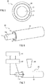
- FIG. 1 is an enlarged front view illustrating an exemplary piezoelectric wire of the present invention
- FIG. 2 is a perspective view of the piezoelectric wire illustrated in FIG. 1
- a piezoelectric wire 10 of the present invention includes a conductive wire 11 and a polymer piezoelectric layer 12 that coats the conductive wire 11.
- the polymer piezoelectric layer is not formed at an end 11a of the conductive wire 11.
- the polymer piezoelectric layer 12 contains a ⁇ -phase polyvinylidene fluoride-based copolymer, and the conductive wire 11 has a wire diameter of 1.0 mm or less.
- the piezoelectric wire is polarized without after-treatment such as drawing, has a piezoelectric property, and exhibits an inverse piezoelectric effect and a positive piezoelectric effect. Moreover, since the wire diameter of the metal wire is set to 1.0 mm or less, the piezoelectric wire is flexible and has high sensitivity.
- FIG. 3 is an enlarged front view illustrating another exemplary piezoelectric wire of the present invention
- FIG. 4 is a perspective view of the piezoelectric wire illustrated in FIG. 3
- a piezoelectric wire 20 illustrated in FIGS. 3 and 4 is a wire obtained by further forming a conductive layer 13 on an outer surface of the polymer piezoelectric layer 12 of the piezoelectric wire 10 illustrated in FIGS. 1 and 2 .
- the formation of the conductive layer 13 facilitates polarization.
- FIG. 5 is an enlarged front view illustrating still another exemplary piezoelectric wire of the present invention
- FIG. 6 is a perspective view of the piezoelectric wire illustrated in FIG. 5
- a piezoelectric wire 30 illustrated in FIGS. 5 and 6 is a wire obtained by further forming an insulating layer 14 on an outer surface of the conductive layer 13 of the piezoelectric wire 20 illustrated in FIGS. 3 and 4 .
- the formation of the insulating layer 14 improves a degree of freedom in an arrangement for installation of the piezoelectric wire 30 to a device or the like.
- the first production method of the piezoelectric wire of the present invention includes: a resin solution preparation step of preparing a resin solution by dissolving a ⁇ -phase polyvinylidene fluoride-based copolymer in a solvent; an application step of applying the resin solution to a conductive wire; a piezoelectric layer formation step of forming a polymer piezoelectric layer on a surface of the conductive wire by heating the conductive wire to which the resin solution has been applied; and a polarization step of polarizing the polymer piezoelectric layer without drawing of the polymer piezoelectric layer.
- the second production method of the piezoelectric wire of the present invention includes: a resin melting step of melting a ⁇ -phase polyvinylidene fluoride-based copolymer by heating to prepare a molten resin; an extrusion coating step of coating a conductive wire with the molten resin to form a polymer piezoelectric layer on a surface of the conductive wire; and a polarization step of polarizing the polymer piezoelectric layer without drawing of the polymer piezoelectric layer.
- the piezoelectric wire obtained thereby can exhibit a strong dielectric property without requiring after-treatment such as drawing.
- a polymer piezoelectric layer having a strong dielectric property can be formed on the conductive wire only by coating the surface with the ⁇ -phase polyvinylidene fluoride-based copolymer.
- the "without drawing of the polymer piezoelectric layer” means that the polymer piezoelectric layer is not drawn before and after polarization.
- the solvent to be used in the first production method is not particularly limited as long as it can dissolve the ⁇ -phase polyvinylidene fluoride-based copolymer and can be removed by heating after application of the resin solution.
- the solvent includes: ketone-based solvents such as methyl ethyl ketone (MEK), methyl isobutyl ketone (MIBK), acetone, diethyl ketone, and dipropyl ketone; ester-based solvents such as ethyl acetate, methyl acetate, propyl acetate, butyl acetate, and ethyl lactate; ether-based solvents such as tetrahydrofuran, methyltetrahydrofuran, and dioxane; and amide-based solvents such as dimethylformamide (DMF) and dimethylacetamide.
- MEK methyl ethyl ketone
- MIBK methyl isobutyl ketone
- the molten resin in the second production method can be prepared, for example, by heating a pelletized ⁇ -phase polyvinylidene fluoride-based copolymer.
- the first and second production methods can further include a step of forming a conductive layer on a surface of the polymer piezoelectric layer.
- the formation method of the conductive layer is not particularly limited, and may be, e.g., an evaporation method, a sputtering method, or a coating method.
- the first and second production methods can further include a step of forming an insulating layer on a surface of the conductive layer.
- the formation method of the insulating layer is not particularly limited, and the layer may be formed similarly to the formation of the polymer piezoelectric layer through the application step or the extrusion coating step.
- polarization in the first and second production methods for example, known corona discharge may be adopted for a piezoelectric wire not having a conductive layer in the form of FIGS. 1 and 2 described above.
- polarization can be performed by applying a direct voltage or an alternating voltage between the conductive wire 11 and the conductive layer 13. It is preferable to form the conductive layer 13 to polarize the polymer piezoelectric layer 12 uniformly.
- a piezoelectric device of the present invention is provided with the piezoelectric wire of the present invention. Since the piezoelectric device of the present invention includes the ultrafine piezoelectric wire functioning as a piezoelectric element, the device has high sensitivity. Since the piezoelectric device of the present invention includes the ultrafine piezoelectric wire with a high degree of freedom in installation inside a device, the device can be downsized.
- Examples of the piezoelectric device for use as a sensor include an impact sensor, a pressure sensing sensor, a pyroelectric sensor, an ultrasonic sensor, a biosignal detecting sensor, a distortion detecting sensor, a microphone, a pickup sensor, an acceleration sensor, a curvature sensor, a keyboard switch, a security sensor, and a vibration power generator.
- Examples of the piezoelectric device for use as an actuator include a speaker, a headphone, a hearing aid, a diaphragm, a compact pump, a shutter, and an artificial muscle.
- the resin solution was applied to a stainless steel single wire 0.02 mm in diameter and 50 mm in length (manufactured by The Nilaco Corporation), by dip coating.
- the single wire to which the resin solution was applied was heated at 150°C for two minutes to vaporize and remove the methyl ethyl ketone, so that a resin layer having a thickness of 20 ⁇ m was formed on the surface of the wire.
- a coated wire was produced. An uncoated wire end part was left on one end of the coated wire.
- Example 1 a piezoelectric wire of Example 1 was produced.
- a piezoelectric wire of Example 2 was produced in the same manner as in Example 1 except that the wire diameter of the stainless steel single wire was 0.10 mm, and the thickness of the resin layer was 15 ⁇ m.
- a piezoelectric wire of Example 3 was produced in the same manner as in Example 1 except that the wire diameter of the stainless steel single wire was 0.50 mm, and the thickness of the resin layer was 80 ⁇ m.
- a piezoelectric wire of Example 4 was produced in the same manner as in Example 1 except that the wire diameter of the stainless steel single wire was 1.0 mm, and the thickness of the resin layer was 80 ⁇ m.
- a function generator "WF 1973" (41) (manufactured by NF Corporation) and an amplifier “Model 610D” (42) (manufactured by TREK, INC.) were connected, and the amplifier (42) was electrically connected with the end 11a of the piezoelectric wire 20 and the conductive layer 13.
- an alternating voltage of 10 Vp-p at a frequency of 5 Hz output from the function generator 41 was amplified to 1000 Vp-p by the amplifier 42 and applied to the piezoelectric wire 20.
- a displacement amplitude p-p (double displacement amplitude) of the piezoelectric wire at this time was measured by a laser microscope "VK-X150" (43) (manufactured by
- both ends of the piezoelectric wire 20 were set in a tensile tester "AGS-500X” (53) (manufactured by Shimadzu Corporation).
- An oscilloscope 51 and a charge amplifier 52 (manufactured by Turtle Industry Co., Ltd.) were connected, and the charge amplifier 52 was electrically connected with the both ends of the piezoelectric wire 20 via electrodes 52a and 52b.
- the both ends of the piezoelectric wire 20 were extended until the tension became 0.5 N, and then the tension was released to 0 at high speed.
- a piezoelectric output at this time was measured to calculate an output voltage per unit thickness of the polymer piezoelectric layer of the piezoelectric wire 20.
- Table 1 indicates the wire diameter and the thickness of the resin layer of each piezoelectric wire, together with the inverse piezoelectric effect and the positive piezoelectric effect.
- FIG. 9 is a graph illustrating a relationship between the wire diameter and the displacement amplitude p-p of the wires of Examples 1 to 4
- FIG. 10 is a graph illustrating a relationship between the wire diameter and the output voltage per unit thickness of the resin layer of the wires of Examples 1 to 4.
- Example 1 Wire diameter (mm) Thickness of resin layer ( ⁇ m) Displacement amplitude p-p ( ⁇ m) Output voltage (mV/ ⁇ m) Example 1 0.02 20 4.26 3.9 Example 2 0.10 15 2.44 2.2 Example 3 0.50 80 0.50 1.6 Example 4 1.0 80 0 1.5 Example 5 0.52 18 0.41 5.6
- the present invention can provide ultrafine piezoelectric wires coated with a polymer piezoelectric material that exhibits a strong dielectric property without after-treatment such as drawing, and the piezoelectric wires can be applied to piezoelectric devices including various sensors and actuators.
Landscapes
- Physics & Mathematics (AREA)
- Engineering & Computer Science (AREA)
- Manufacturing & Machinery (AREA)
- Spectroscopy & Molecular Physics (AREA)
- General Physics & Mathematics (AREA)
- Organic Insulating Materials (AREA)
- Addition Polymer Or Copolymer, Post-Treatments, Or Chemical Modifications (AREA)
- Compositions Of Macromolecular Compounds (AREA)
- Shaping By String And By Release Of Stress In Plastics And The Like (AREA)
- Insulated Conductors (AREA)
- Piezo-Electric Transducers For Audible Bands (AREA)
Abstract
Description
- The present invention relates to an ultrafine piezoelectric wire and a production method of the piezoelectric wire, and a piezoelectric device including the piezoelectric wire.
- Piezoelectric elements are elements utilizing piezoelectric materials, which are substances converting an electrical energy into a mechanical energy or a mechanical energy into an electrical energy. The piezoelectric elements are used for various actuators by utilizing the inverse piezoelectric effect of converting an electrical energy into a mechanical energy, and for various sensors and vibration-type power generation elements by utilizing the positive piezoelectric effect of converting a mechanical energy into an electrical energy.
- Along with downsizing of devices utilizing piezoelectric elements, cable-like piezoelectric elements with a high degree of freedom in installation to devices have drawn attention recently. For example, Patent Document 1 proposes a cable-like piezoelectric sensor comprising an internal conductor, a flexible insulator, an outer conductor including a piezoelectric layer and a metal layer, and a flexible sheath. A polymer piezoelectric material such as polyvinylidene fluoride is used for the piezoelectric layer.
-
- Patent Document 1:
JP 2005-351664 A - Patent Document 2:
JP 2005-200623 A - However, polyvinylidene fluoride, which is described to be usable as a piezoelectric material in Patent Document 1, requires complex after-treatment such as drawing to exhibit a strong dielectric property. In the case of using polyvinylidene fluoride by coating on a fine metal wire or the like, it is difficult to perform after-treatment such as drawing after the coating. There is also a method in which polyvinylidene fluoride is formed into a film and then drawn, and the drawn film is attached to a metal wire to cover the metal wire. However, this method is difficult to implement when the metal wire is thin.
- The present invention has been achieved to solve the above problem, and its object is to provide an ultrafine piezoelectric wire that is coated with a polymer piezoelectric material that exhibits a strong dielectric property without requiring after-treatment such as drawing.
- A piezoelectric wire of the present invention is a piezoelectric wire including a conductive wire and a polymer piezoelectric layer that coats the conductive wire. The polymer piezoelectric layer contains a β-phase polyvinylidene fluoride-based copolymer, and the conductive wire has a wire diameter of 1.0 mm or less.
- A piezoelectric device of the present invention includes the piezoelectric wire of the present invention.
- A first production method of the piezoelectric wire of the present invention includes: a resin solution preparation step of preparing a resin solution by dissolving a β-phase polyvinylidene fluoride-based copolymer in a solvent; an application step of applying the resin solution to a conductive wire; a piezoelectric layer formation step of forming a polymer piezoelectric layer on a surface of the conductive wire by heating the conductive wire to which the resin solution has been applied; and a polarization step of polarizing the polymer piezoelectric layer without drawing of the polymer piezoelectric layer.
- A second production method of the piezoelectric wire of the present invention includes: a resin melting step of melting a β-phase polyvinylidene fluoride-based copolymer by heating to prepare a molten resin; an extrusion coating step of coating a conductive wire with the molten resin to form a polymer piezoelectric layer on a surface of the conductive wire; and a polarization step of polarizing the polymer piezoelectric layer without drawing of the polymer piezoelectric layer.
- The present invention provides an ultrafine, high-sensitive piezoelectric wire coated with a polymer piezoelectric material that exhibits a strong dielectric property without requiring after-treatment such as drawing.
-
- [
FIG. 1] FIG. 1 is an enlarged front view illustrating an exemplary piezoelectric wire of the present invention. - [
FIG. 2] FIG. 2 is a perspective view of the piezoelectric wire illustrated inFIG. 1 . - [
FIG. 3] FIG. 3 is an enlarged front view illustrating another exemplary piezoelectric wire of the present invention. - [
FIG. 4] FIG. 4 is a perspective view of the piezoelectric wire illustrated inFIG. 3 . - [
FIG. 5] FIG. 5 is an enlarged front view illustrating another exemplary piezoelectric wire of the present invention. -
[FIG. 6] FIG. 6 is a perspective view of the piezoelectric wire illustrated inFIG. 5 . -
[FIG. 7] FIG. 7 is a schematic diagram illustrating a state of measuring an inverse piezoelectric effect of the piezoelectric wire of the present invention. - [
FIG. 8] FIG. 8 is a schematic diagram illustrating a state of measuring a positive piezoelectric effect of the piezoelectric wire of the present invention. - [
FIG. 9] FIG. 9 is a graph illustrating a relationship between a wire diameter and a displacement amplitude p-p of wires of Examples 1 to 4. - [
FIG. 10] FIG. 10 is a graph illustrating a relationship between a wire diameter and an output voltage per unit thickness of a resin layer of the wires of Examples 1 to 4. - First, a piezoelectric wire of the present invention will be described. The piezoelectric wire of the present invention includes a conductive wire and a polymer piezoelectric layer that coats the conductive wire. The polymer piezoelectric layer contains a β-phase polyvinylidene fluoride-based copolymer, and the conductive wire has a wire diameter (diameter) of 1.0 mm or less.
- Since a β-phase polyvinylidene fluoride-based copolymer is used as a piezoelectric material in the piezoelectric wire of the present invention, the piezoelectric wire can exhibit a strong dielectric property without requiring after-treatment such as drawing. Because of this, even when the wire diameter of the conductive wire is 1.0 mm or less, polarization becomes possible and a polymer piezoelectric layer can be formed merely by coating the surface of the conductive wire with the β-phase polyvinylidene fluoride-based copolymer. Thus, a piezoelectric wire with a high degree of freedom in installation to a device can be produced.
- Moreover, in the piezoelectric wire of the present invention, since the wire diameter of the conductive wire is set to 1.0 mm or less, the piezoelectric wire is flexible and has high sensitivity to exhibit an inverse piezoelectric effect and a positive piezoelectric effect. In other words, the piezoelectric wire of the present invention as a flexible piezoelectric element can reliably convert even a small electrical energy into a mechanical energy and convert even a small mechanical energy into an electrical energy.
- The β-phase polyvinylidene fluoride-based copolymer is preferably at least one selected from a vinylidene fluoride-trifluoroethylene copolymer and a vinylidene fluoride-tetrafluoroethylene copolymer because these copolymers have a strong dielectric property and high heat resistance. Here, the "strong dielectric property" is a property of maintaining polarization even when there is no external electric field. The "heat resistance" is a property of maintaining polarization even when the temperature is at 85°C.
- The "vinylidene fluoride-trifluoroethylene copolymer" contains 50 mol% or more (preferably 60 mol% or more) of a repeating unit derived from vinylidene fluoride. A mole ratio of (a repeating unit derived from trifluoroethylene) / (the repeating unit derived from vinylidene fluoride) in the "vinylidene fluoride-trifluoroethylene copolymer" is preferably within a range of 5/95 to 36/64, more preferably within a range of 15/85 to 25/75, and further preferably within a range of 18/82 to 22/78.
- The "vinylidene fluoride-tetrafluoroethylene copolymer" contains 50 mol% or more (preferably 60 mol% or more) of a repeating unit derived from vinylidene fluoride. A mole ratio of (a repeating unit derived from tetrafluoroethylene) / (the repeating unit derived from vinylidene fluoride) in the "vinylidene fluoride-tetrafluoroethylene copolymer" is preferably within a range of 5/95 to 36/64, more preferably within a range of 15/85 to 25/75, and further preferably within a range of 18/82 to 22/78.
- The molecular weight of the β-phase polyvinylidene fluoride-based copolymer is not particularly limited, and for example, polymers having a number average molecular weight of 10,000 to 1,000,000 may be used.
- The polymer piezoelectric layer may contain an additive in addition to the β-phase polyvinylidene fluoride-based copolymer. Examples of the additive include piezoelectric ceramic such as lead titanate sintered powder, lead zirconate titanate sintered powder, non-lead piezoelectric ceramic sintered powder (e.g., sodium niobate), and aluminum nitride.
- The thickness of the polymer piezoelectric layer is not particularly limited, but it is generally set to 2 µm or more and 200 µm or less because the flexibility and sensitivity of the piezoelectric wire tend to deteriorate when the polymer piezoelectric layer is too thick.
- Although the conductive wire is set to have a wire diameter of 1.0 mm or less, it is preferably ultrafine with a wire diameter of 0.5 mm or less. By doing so, it is possible to obtain a piezoelectric wire having more flexibility and higher sensitivity to exhibit an inverse piezoelectric effect and a positive piezoelectric effect. The lower limit of the wire diameter of the conductive wire is not particularly limited as long as the conductive wire is produceable. For example, the wire diameter is set to 0.008 mm or more for smoother handling and production of the wire.
- The type of the conductive wire is not particularly limited as long as the wire has conductivity, and examples thereof include a metal wire, a conductive-coated wire in which a surface of a resin wire is coated with a conductive layer, and a conductive polymer wire. Among these, a metal wire having a high tensile strength is preferred. When the conductive wire is a metal wire, the type of the metal to be used is not particularly limited, and examples thereof include copper, nickel, aluminum, and stainless steel.
- The form of the conductive wire is not particularly limited, and examples thereof include a single wire and a strand.
- The piezoelectric wire of the present invention may further include a conductive layer on an outer surface of the polymer piezoelectric layer. The material for forming the conductive layer is not particularly limited, and examples thereof include a metal and a conductive polymer.
- The piezoelectric wire of the present invention may further include an insulating layer on an outer surface of the conductive layer. This improves a degree of freedom in an arrangement for installation of the piezoelectric wire of the present invention to a device or the like. The material for forming the insulating layer is not particularly limited, and examples thereof include an organic material and an inorganic material. A resin material with flexibility is preferred.
- Hereinafter, the piezoelectric wire of the present invention will be described with reference to the drawings.
FIG. 1 is an enlarged front view illustrating an exemplary piezoelectric wire of the present invention, andFIG. 2 is a perspective view of the piezoelectric wire illustrated inFIG. 1 . InFIGS. 1 and 2 , apiezoelectric wire 10 of the present invention includes aconductive wire 11 and apolymer piezoelectric layer 12 that coats theconductive wire 11. The polymer piezoelectric layer is not formed at anend 11a of theconductive wire 11. Thepolymer piezoelectric layer 12 contains a β-phase polyvinylidene fluoride-based copolymer, and theconductive wire 11 has a wire diameter of 1.0 mm or less. - The piezoelectric wire is polarized without after-treatment such as drawing, has a piezoelectric property, and exhibits an inverse piezoelectric effect and a positive piezoelectric effect. Moreover, since the wire diameter of the metal wire is set to 1.0 mm or less, the piezoelectric wire is flexible and has high sensitivity.
-
FIG. 3 is an enlarged front view illustrating another exemplary piezoelectric wire of the present invention, andFIG. 4 is a perspective view of the piezoelectric wire illustrated inFIG. 3 . Apiezoelectric wire 20 illustrated inFIGS. 3 and 4 is a wire obtained by further forming aconductive layer 13 on an outer surface of thepolymer piezoelectric layer 12 of thepiezoelectric wire 10 illustrated inFIGS. 1 and 2 . The formation of theconductive layer 13 facilitates polarization. -
FIG. 5 is an enlarged front view illustrating still another exemplary piezoelectric wire of the present invention, andFIG. 6 is a perspective view of the piezoelectric wire illustrated inFIG. 5 . Apiezoelectric wire 30 illustrated inFIGS. 5 and 6 is a wire obtained by further forming an insulatinglayer 14 on an outer surface of theconductive layer 13 of thepiezoelectric wire 20 illustrated inFIGS. 3 and 4 . The formation of the insulatinglayer 14 improves a degree of freedom in an arrangement for installation of thepiezoelectric wire 30 to a device or the like. - Next, first and second production methods of the piezoelectric wire of the present invention will be described.
- The first production method of the piezoelectric wire of the present invention includes: a resin solution preparation step of preparing a resin solution by dissolving a β-phase polyvinylidene fluoride-based copolymer in a solvent; an application step of applying the resin solution to a conductive wire; a piezoelectric layer formation step of forming a polymer piezoelectric layer on a surface of the conductive wire by heating the conductive wire to which the resin solution has been applied; and a polarization step of polarizing the polymer piezoelectric layer without drawing of the polymer piezoelectric layer.
- The second production method of the piezoelectric wire of the present invention includes: a resin melting step of melting a β-phase polyvinylidene fluoride-based copolymer by heating to prepare a molten resin; an extrusion coating step of coating a conductive wire with the molten resin to form a polymer piezoelectric layer on a surface of the conductive wire; and a polarization step of polarizing the polymer piezoelectric layer without drawing of the polymer piezoelectric layer.
- Since the β-phase polyvinylidene fluoride-based copolymer is used as a piezoelectric material in the first and second production methods of the piezoelectric wire of the present invention, the piezoelectric wire obtained thereby can exhibit a strong dielectric property without requiring after-treatment such as drawing. Thus, even when the wire diameter of the conductive wire is as thin as 1.0 mm or less, a polymer piezoelectric layer having a strong dielectric property can be formed on the conductive wire only by coating the surface with the β-phase polyvinylidene fluoride-based copolymer. Thus, an ultrafine piezoelectric wire with a high degree of freedom in installation to a device can be produced.
- Here, the "without drawing of the polymer piezoelectric layer" means that the polymer piezoelectric layer is not drawn before and after polarization.
- The solvent to be used in the first production method is not particularly limited as long as it can dissolve the β-phase polyvinylidene fluoride-based copolymer and can be removed by heating after application of the resin solution. Examples of the solvent includes: ketone-based solvents such as methyl ethyl ketone (MEK), methyl isobutyl ketone (MIBK), acetone, diethyl ketone, and dipropyl ketone; ester-based solvents such as ethyl acetate, methyl acetate, propyl acetate, butyl acetate, and ethyl lactate; ether-based solvents such as tetrahydrofuran, methyltetrahydrofuran, and dioxane; and amide-based solvents such as dimethylformamide (DMF) and dimethylacetamide.
- The molten resin in the second production method can be prepared, for example, by heating a pelletized β-phase polyvinylidene fluoride-based copolymer.
- The first and second production methods can further include a step of forming a conductive layer on a surface of the polymer piezoelectric layer. The formation method of the conductive layer is not particularly limited, and may be, e.g., an evaporation method, a sputtering method, or a coating method.
- Moreover, the first and second production methods can further include a step of forming an insulating layer on a surface of the conductive layer. The formation method of the insulating layer is not particularly limited, and the layer may be formed similarly to the formation of the polymer piezoelectric layer through the application step or the extrusion coating step.
- As to the polarization in the first and second production methods, for example, known corona discharge may be adopted for a piezoelectric wire not having a conductive layer in the form of
FIGS. 1 and 2 described above. For a piezoelectric wire having a conductive layer in the form ofFIGS. 3 and 4 , polarization can be performed by applying a direct voltage or an alternating voltage between theconductive wire 11 and theconductive layer 13. It is preferable to form theconductive layer 13 to polarize thepolymer piezoelectric layer 12 uniformly. - A piezoelectric device of the present invention is provided with the piezoelectric wire of the present invention. Since the piezoelectric device of the present invention includes the ultrafine piezoelectric wire functioning as a piezoelectric element, the device has high sensitivity. Since the piezoelectric device of the present invention includes the ultrafine piezoelectric wire with a high degree of freedom in installation inside a device, the device can be downsized.
- Examples of the piezoelectric device for use as a sensor include an impact sensor, a pressure sensing sensor, a pyroelectric sensor, an ultrasonic sensor, a biosignal detecting sensor, a distortion detecting sensor, a microphone, a pickup sensor, an acceleration sensor, a curvature sensor, a keyboard switch, a security sensor, and a vibration power generator. Examples of the piezoelectric device for use as an actuator include a speaker, a headphone, a hearing aid, a diaphragm, a compact pump, a shutter, and an artificial muscle.
- Hereinafter, the present invention will be described in more detail based on examples. However, the present invention is not limited to the following examples.
- First, 30g of a vinylidene fluoride-trifluoroethylene copolymer (the mole ratio of vinylidene fluoride : trifluoroethylene = 75 : 25) was dissolved in 70 g of methyl ethyl ketone while heating to 70°C, and the mixture was stirred for 30 minutes by an ultrasonic homogenizer "BRANSON Digital Sonifire" (manufactured by Emerson Japan, Ltd.) to prepare a resin solution.
- Next, the resin solution was applied to a stainless steel single wire 0.02 mm in diameter and 50 mm in length (manufactured by The Nilaco Corporation), by dip coating. The single wire to which the resin solution was applied was heated at 150°C for two minutes to vaporize and remove the methyl ethyl ketone, so that a resin layer having a thickness of 20 µm was formed on the surface of the wire. Thus, a coated wire was produced. An uncoated wire end part was left on one end of the coated wire.
- Then, aluminum was evaporated on the entire surface of the resin layer of the coated wire to form an aluminum conductive layer. Next, using the aluminum conductive layer as a ground electrode and the uncoated wire end part as a counter electrode, the resin layer was polarized by applying a direct voltage of 6 kV from the counter electrode to the ground electrode for one minute by a high-voltage supply "610D" (manufactured by TREK, INC.). Thus, a piezoelectric wire of Example 1 was produced.
- A piezoelectric wire of Example 2 was produced in the same manner as in Example 1 except that the wire diameter of the stainless steel single wire was 0.10 mm, and the thickness of the resin layer was 15 µm.
- A piezoelectric wire of Example 3 was produced in the same manner as in Example 1 except that the wire diameter of the stainless steel single wire was 0.50 mm, and the thickness of the resin layer was 80 µm.
- A piezoelectric wire of Example 4 was produced in the same manner as in Example 1 except that the wire diameter of the stainless steel single wire was 1.0 mm, and the thickness of the resin layer was 80 µm.
- A piezoelectric wire of Example 5 was produced in the same manner as in Example 1 except that a vinylidene fluoride-tetrafluoroethylene copolymer (the mole ratio of vinylidene fluoride : tetrafluoroethylene = 80 : 20) was used as a piezoelectric resin, a copper strand (wire diameter: 0.52 mm) 50 mm in length in which 20 copper single wires (wire diameter: 0.08 mm) were twisted together was used as a wire, and the thickness of the resin layer was 18 µm.
- The inverse piezoelectric effect and the positive piezoelectric effect of the piezoelectric wires of Examples 1 to 5 were evaluated as below.
- As illustrated in
FIG. 7 , a function generator "WF 1973" (41) (manufactured by NF Corporation) and an amplifier "Model 610D" (42) (manufactured by TREK, INC.) were connected, and the amplifier (42) was electrically connected with theend 11a of thepiezoelectric wire 20 and theconductive layer 13. Next, an alternating voltage of 10 Vp-p at a frequency of 5 Hz output from thefunction generator 41 was amplified to 1000 Vp-p by theamplifier 42 and applied to thepiezoelectric wire 20. A displacement amplitude p-p (double displacement amplitude) of the piezoelectric wire at this time was measured by a laser microscope "VK-X150" (43) (manufactured by - As illustrated in
FIG. 8 , both ends of thepiezoelectric wire 20 were set in a tensile tester "AGS-500X" (53) (manufactured by Shimadzu Corporation). Anoscilloscope 51 and a charge amplifier 52 (manufactured by Turtle Industry Co., Ltd.) were connected, and thecharge amplifier 52 was electrically connected with the both ends of thepiezoelectric wire 20 viaelectrodes piezoelectric wire 20 were extended until the tension became 0.5 N, and then the tension was released to 0 at high speed. A piezoelectric output at this time was measured to calculate an output voltage per unit thickness of the polymer piezoelectric layer of thepiezoelectric wire 20. - The results are shown in Table 1,
FIGS. 9 and10 . Table 1 indicates the wire diameter and the thickness of the resin layer of each piezoelectric wire, together with the inverse piezoelectric effect and the positive piezoelectric effect.FIG. 9 is a graph illustrating a relationship between the wire diameter and the displacement amplitude p-p of the wires of Examples 1 to 4, andFIG. 10 is a graph illustrating a relationship between the wire diameter and the output voltage per unit thickness of the resin layer of the wires of Examples 1 to 4.[Table 1] Wire diameter (mm) Thickness of resin layer (µm) Displacement amplitude p-p (µm) Output voltage (mV/µm) Example 1 0.02 20 4.26 3.9 Example 2 0.10 15 2.44 2.2 Example 3 0.50 80 0.50 1.6 Example 4 1.0 80 0 1.5 Example 5 0.52 18 0.41 5.6 - It was confirmed from Table 1 and
FIG. 9 that, since the displacement amplitude p-p was observed in Examples 1 to 3 and 5, the piezoelectric wires of Examples 1 to 3 and 5 can exhibit the inverse piezoelectric effect. It was also confirmed from Table 1 andFIG. 10 that the piezoelectric wires of Examples 1 to 5 can exhibit the positive piezoelectric effect. - Moreover, the above results indicate that both the inverse piezoelectric effect and the positive piezoelectric effect improve as the wire diameter decreases.
- The invention may be embodied in other forms without departing from the spirit or essential characteristics thereof. The embodiments disclosed in this application are to be considered in all respects as illustrative and not limiting. The scope of the invention is indicated by the appended claims rather than by the foregoing description, and all changes which come within the meaning and range of equivalency of the claims are intended to be embraced therein.
- The present invention can provide ultrafine piezoelectric wires coated with a polymer piezoelectric material that exhibits a strong dielectric property without after-treatment such as drawing, and the piezoelectric wires can be applied to piezoelectric devices including various sensors and actuators.
-
- 10, 20, 30
- piezoelectric wire
- 11
- conductive wire
- 11a
- wire end
- 12
- polymer piezoelectric layer
- 13
- conductive layer
- 14
- insulating layer
- 41
- function generator
- 42
- amplifier
- 43
- laser microscope
- 51
- oscilloscope
- 52
- charge amplifier
- 52a, 52b
- electrode
- 53
- tensile tester
Claims (13)
- A piezoelectric wire comprising a conductive wire and a polymer piezoelectric layer that coats the conductive wire,
wherein the polymer piezoelectric layer contains a β-phase polyvinylidene fluoride-based copolymer, and
the conductive wire has a wire diameter of 1.0 mm or less. - The piezoelectric wire according to claim 1, wherein the β-phase polyvinylidene fluoride-based copolymer is at least one selected from a vinylidene fluoride-trifluoroethylene copolymer and a vinylidene fluoride-tetrafluoroethylene copolymer.
- The piezoelectric wire according to claim 1 or 2, wherein the polymer piezoelectric layer has a thickness of 2 µm or more and 200 µm or less.
- The piezoelectric wire according to any one of claims 1 to 3, wherein the conductive wire has a wire diameter of 0.5 mm or less.
- The piezoelectric wire according to any one of claims 1 to 4, wherein the conductive wire has a wire diameter of 0.008 mm or more.
- The piezoelectric wire according to any one of claims 1 to 5, wherein the conductive wire is a metal wire.
- The piezoelectric wire according to any one of claims 1 to 6, further comprising a conductive layer on an outer surface of the polymer piezoelectric layer.
- The piezoelectric wire according to claim 7, further comprising an insulating layer on an outer surface of the conductive layer.
- A piezoelectric device comprising the piezoelectric wire according to any one of claims 1 to 8.
- A method for producing the piezoelectric wire according to any one of claims 1 to 8, comprising:a resin solution preparation step of preparing a resin solution by dissolving a β-phase polyvinylidene fluoride-based copolymer in a solvent;an application step of applying the resin solution to a conductive wire;a piezoelectric layer formation step of forming a polymer piezoelectric layer on a surface of the conductive wire by heating the conductive wire to which the resin solution has been applied; anda polarization step of polarizing the polymer piezoelectric layer without drawing of the polymer piezoelectric layer.
- A method for producing the piezoelectric wire according to any one of claims 1 to 8, comprising:a resin melting step of melting a β-phase polyvinylidene fluoride-based copolymer by heating to prepare a molten resin;an extrusion coating step of coating a conductive wire with the molten resin to form a polymer piezoelectric layer on a surface of the conductive wire; anda polarization step of polarizing the polymer piezoelectric layer without drawing of the polymer piezoelectric layer.
- The production method according to claim 10 or 11, further comprising a step of forming a conductive layer on a surface of the polymer piezoelectric layer.
- The production method according to claim 12, further comprising a step of forming an insulating layer on a surface of the conductive layer.
Applications Claiming Priority (2)
| Application Number | Priority Date | Filing Date | Title |
|---|---|---|---|
| JP2016070220A JP6725290B2 (en) | 2016-03-31 | 2016-03-31 | Piezoelectric wire, method of manufacturing the same, and piezoelectric device including the piezoelectric wire |
| PCT/JP2017/012240 WO2017170323A1 (en) | 2016-03-31 | 2017-03-27 | Piezoelectric wire and production method for same, and piezoelectric device provided with piezoelectric wire |
Publications (2)
| Publication Number | Publication Date |
|---|---|
| EP3442040A1 true EP3442040A1 (en) | 2019-02-13 |
| EP3442040A4 EP3442040A4 (en) | 2019-12-04 |
Family
ID=59964411
Family Applications (1)
| Application Number | Title | Priority Date | Filing Date |
|---|---|---|---|
| EP17774860.5A Withdrawn EP3442040A4 (en) | 2016-03-31 | 2017-03-27 | PIEZOELECTRIC WIRE, ITS MANUFACTURING METHOD AND PIEZOELECTRIC DEVICE WITH PIEZOELECTRIC WIRE |
Country Status (7)
| Country | Link |
|---|---|
| US (1) | US20190109274A1 (en) |
| EP (1) | EP3442040A4 (en) |
| JP (1) | JP6725290B2 (en) |
| KR (1) | KR20180127394A (en) |
| CN (1) | CN108886088A (en) |
| TW (1) | TW201810742A (en) |
| WO (1) | WO2017170323A1 (en) |
Families Citing this family (10)
| Publication number | Priority date | Publication date | Assignee | Title |
|---|---|---|---|---|
| JP6924516B2 (en) * | 2017-12-11 | 2021-08-25 | ロボセンサー技研株式会社 | Linear sensor, strip sensor, and planar sensor |
| JP7102762B2 (en) * | 2018-02-09 | 2022-07-20 | 日立金属株式会社 | Piezoelectric member |
| JP6501958B1 (en) * | 2018-09-06 | 2019-04-17 | 東邦化成株式会社 | Piezoelectric element |
| FR3090665B1 (en) | 2018-12-20 | 2020-12-11 | Arkema France | PIEZOELECTRIC COMPOSITE FIBER |
| JP7416376B2 (en) * | 2019-11-27 | 2024-01-17 | ダイキンファインテック株式会社 | Piezoelectric elements and piezoelectric devices |
| CN115298841A (en) | 2020-03-09 | 2022-11-04 | 株式会社藤仓 | Piezoelectric coaxial sensor |
| EP4120373B1 (en) * | 2020-03-09 | 2025-10-08 | Fujikura Ltd. | Piezoelectric coaxial sensor and method for manufacturing piezoelectric coaxial sensor |
| US11849642B2 (en) * | 2020-04-17 | 2023-12-19 | Wisconsin Alumni Research Foundation | 3D printed and in-situ poled flexible piezoelectric pressure sensor |
| JP7517101B2 (en) * | 2020-11-17 | 2024-07-17 | 株式会社プロテリアル | Quality control method for polymeric piezoelectric material, method for manufacturing resin composition, method for manufacturing cable or tube, method for manufacturing piezoelectric element, method for manufacturing pyroelectric sensor, and method for manufacturing nonvolatile thin film memory |
| CN114566329B (en) * | 2022-02-14 | 2022-11-18 | 苏州大学 | Piezoelectric cable and preparation method thereof |
Family Cites Families (13)
| Publication number | Priority date | Publication date | Assignee | Title |
|---|---|---|---|---|
| US4568851A (en) * | 1984-09-11 | 1986-02-04 | Raychem Corporation | Piezoelectric coaxial cable having a helical inner conductor |
| JPS61276280A (en) * | 1985-05-30 | 1986-12-06 | Central Glass Co Ltd | High-molecular piezoelectric material |
| JP3867709B2 (en) * | 2003-03-26 | 2007-01-10 | ダイキン工業株式会社 | Thin film formation method |
| JP4348480B2 (en) * | 2004-06-08 | 2009-10-21 | 独立行政法人産業技術総合研究所 | Cable-shaped piezoelectric sensor |
| JP2006080366A (en) * | 2004-09-10 | 2006-03-23 | Matsushita Electric Ind Co Ltd | Cable-shaped piezoelectric element and vibration detection sensor using the same |
| JP2006098062A (en) * | 2004-09-28 | 2006-04-13 | Oki Electric Cable Co Ltd | Highly sensitive/highly bendable sensor cable |
| CN101508841B (en) * | 2009-03-17 | 2012-02-08 | 武汉理工大学 | Flexible polymer dielectric material for electrical condenser and preparation thereof |
| JP5291551B2 (en) * | 2009-06-26 | 2013-09-18 | 株式会社クレハ | Polymer composition and polymer piezoelectric film |
| JP5714235B2 (en) * | 2010-03-11 | 2015-05-07 | 株式会社クレハ | Additive-free and non-stretched piezoelectric body and PV sensor containing PVDF |
| JP5588702B2 (en) * | 2010-03-11 | 2014-09-10 | 株式会社クレハ | Non-stretched piezoelectric body and PV sensor containing PVDF |
| EP2908357B1 (en) * | 2012-10-12 | 2018-08-29 | Teijin Limited | Piezoelectric element |
| US20150332855A1 (en) * | 2012-11-20 | 2015-11-19 | Daikin Industries, Ltd. | Multilayer film |
| KR20150134956A (en) * | 2014-05-22 | 2015-12-02 | 주식회사 광세로 | Linear type piezoelectric element with flexibility |
-
2016
- 2016-03-31 JP JP2016070220A patent/JP6725290B2/en active Active
-
2017
- 2017-03-27 WO PCT/JP2017/012240 patent/WO2017170323A1/en not_active Ceased
- 2017-03-27 EP EP17774860.5A patent/EP3442040A4/en not_active Withdrawn
- 2017-03-27 KR KR1020187029088A patent/KR20180127394A/en not_active Withdrawn
- 2017-03-27 US US16/087,885 patent/US20190109274A1/en not_active Abandoned
- 2017-03-27 CN CN201780020474.4A patent/CN108886088A/en active Pending
- 2017-03-29 TW TW106110551A patent/TW201810742A/en unknown
Also Published As
| Publication number | Publication date |
|---|---|
| CN108886088A (en) | 2018-11-23 |
| EP3442040A4 (en) | 2019-12-04 |
| WO2017170323A1 (en) | 2017-10-05 |
| KR20180127394A (en) | 2018-11-28 |
| JP2017183570A (en) | 2017-10-05 |
| US20190109274A1 (en) | 2019-04-11 |
| JP6725290B2 (en) | 2020-07-15 |
| TW201810742A (en) | 2018-03-16 |
Similar Documents
| Publication | Publication Date | Title |
|---|---|---|
| US20190109274A1 (en) | Piezoelectric wire and production method for same, and piezoelectric device provided with piezoelectric wire | |
| EP3848986B1 (en) | Piezoelectric element | |
| KR101694579B1 (en) | Polymer composite piezoelectric body and method for producing same | |
| US12035632B2 (en) | Flexible and low cost piezoelectric composites with high d33 values | |
| Chary et al. | Dopamine-modified Ba0. 85Ca0. 15Zr0. 1Ti0. 9O3 ultra-fine fibers/PVDF-HFP composite–based nanogenerator: synergistic effect on output electric signal | |
| KR101471161B1 (en) | A piezoelectric device comprising a? -Phase PVDF film produced by spray coating | |
| JP5795976B2 (en) | Method for forming a piezoelectric resin film having a high piezoelectric constant on the surface of an object to be coated | |
| Zakeri et al. | Enhancing the piezoelectricity of PVDF-BaTiO3 nanofibers by incorporation of ZnO nanoparticles fabricated via two-way electrospinning technique | |
| JP2019062124A (en) | Heat resistant piezoelectric wire and piezoelectric device provided with heat resistant piezoelectric wire | |
| KR20240092825A (en) | Piezoelectric composite fiber with improved piezoelectric performance, manufacturing method thereof, and flexible piezoelectric energy harvester comprising the same | |
| Kibria et al. | Detection of high sensitive acoustic region for sensible applications of electrospinning based PVDF-TrFE nanofiber sensor | |
| KR102810696B1 (en) | Piezoelectric device comprising a membrane comprising fibers of polyhydroxyalkanoate | |
| Kibria et al. | Electrospinning-based high-sensitive PVDF-TrFE nanofibre sensor with sensitivity dependence on pore diameter | |
| JP6395470B2 (en) | Thermoplastic polyurea thin film, laminate thereof, and production method thereof | |
| KR20140097872A (en) | PREPARATION METHOD OF β-PHASE PVDF FILM USING SPRAY COATING | |
| JPWO2018181261A1 (en) | Piezoelectric element | |
| KR101348902B1 (en) | Preparation method of generating element having b-phase pvdf film using spray coating | |
| JP7416376B2 (en) | Piezoelectric elements and piezoelectric devices | |
| Kumar et al. | Pyroelectric and piezoelectric polymers | |
| JP2018526823A (en) | Moisture-resistant protective layer | |
| Marandi et al. | Experimental Study of the Effect of Corona Poling Parameters on Additive Manufactured Pyroelectric PVDF-TrFE Sensors | |
| JP5729701B2 (en) | Composite dielectric element | |
| George | Preparation and Characterization of Poly (PVDF-HFP)–Aluminum Nitride (AlN) Nanocomposite for the Fabrication of Piezoelectric Nanogenerators. | |
| Asghar et al. | Synergistic improvement in piezoelectric, electrical, and mechanical properties of PVDF/PZT/Clay based Hybrid Nanocomposites | |
| Parfenovich et al. | Development of Lamination-Based Technological Approach for Encapsulation of Ionic EAP Sensors |
Legal Events
| Date | Code | Title | Description |
|---|---|---|---|
| STAA | Information on the status of an ep patent application or granted ep patent |
Free format text: STATUS: THE INTERNATIONAL PUBLICATION HAS BEEN MADE |
|
| PUAI | Public reference made under article 153(3) epc to a published international application that has entered the european phase |
Free format text: ORIGINAL CODE: 0009012 |
|
| STAA | Information on the status of an ep patent application or granted ep patent |
Free format text: STATUS: REQUEST FOR EXAMINATION WAS MADE |
|
| 17P | Request for examination filed |
Effective date: 20181022 |
|
| AK | Designated contracting states |
Kind code of ref document: A1 Designated state(s): AL AT BE BG CH CY CZ DE DK EE ES FI FR GB GR HR HU IE IS IT LI LT LU LV MC MK MT NL NO PL PT RO RS SE SI SK SM TR |
|
| AX | Request for extension of the european patent |
Extension state: BA ME |
|
| DAV | Request for validation of the european patent (deleted) | ||
| DAX | Request for extension of the european patent (deleted) | ||
| A4 | Supplementary search report drawn up and despatched |
Effective date: 20191104 |
|
| RIC1 | Information provided on ipc code assigned before grant |
Ipc: G01L 1/16 20060101ALI20191028BHEP Ipc: H01L 41/193 20060101ALI20191028BHEP Ipc: H01L 41/113 20060101ALI20191028BHEP Ipc: H01L 41/09 20060101ALI20191028BHEP Ipc: H01L 41/087 20060101AFI20191028BHEP Ipc: H01L 41/333 20130101ALI20191028BHEP Ipc: H01L 41/45 20130101ALI20191028BHEP |
|
| STAA | Information on the status of an ep patent application or granted ep patent |
Free format text: STATUS: THE APPLICATION IS DEEMED TO BE WITHDRAWN |
|
| 18D | Application deemed to be withdrawn |
Effective date: 20200603 |