EP3442002A1 - Operationssequenzbearbeitungsvorrichtung, analysesteuerungssystem, analysesystem und betriebssequenzbearbeitungsverfahren - Google Patents
Operationssequenzbearbeitungsvorrichtung, analysesteuerungssystem, analysesystem und betriebssequenzbearbeitungsverfahren Download PDFInfo
- Publication number
- EP3442002A1 EP3442002A1 EP18187743.2A EP18187743A EP3442002A1 EP 3442002 A1 EP3442002 A1 EP 3442002A1 EP 18187743 A EP18187743 A EP 18187743A EP 3442002 A1 EP3442002 A1 EP 3442002A1
- Authority
- EP
- European Patent Office
- Prior art keywords
- operation sequence
- contents
- display
- screen
- analysis
- Prior art date
- Legal status (The legal status is an assumption and is not a legal conclusion. Google has not performed a legal analysis and makes no representation as to the accuracy of the status listed.)
- Withdrawn
Links
Images




Classifications
-
- G—PHYSICS
- G06—COMPUTING OR CALCULATING; COUNTING
- G06F—ELECTRIC DIGITAL DATA PROCESSING
- G06F3/00—Input arrangements for transferring data to be processed into a form capable of being handled by the computer; Output arrangements for transferring data from processing unit to output unit, e.g. interface arrangements
- G06F3/01—Input arrangements or combined input and output arrangements for interaction between user and computer
- G06F3/048—Interaction techniques based on graphical user interfaces [GUI]
- G06F3/0484—Interaction techniques based on graphical user interfaces [GUI] for the control of specific functions or operations, e.g. selecting or manipulating an object, an image or a displayed text element, setting a parameter value or selecting a range
- G06F3/04847—Interaction techniques to control parameter settings, e.g. interaction with sliders or dials
-
- H—ELECTRICITY
- H01—ELECTRIC ELEMENTS
- H01J—ELECTRIC DISCHARGE TUBES OR DISCHARGE LAMPS
- H01J49/00—Particle spectrometers or separator tubes
- H01J49/0027—Methods for using particle spectrometers
- H01J49/0031—Step by step routines describing the use of the apparatus
-
- G—PHYSICS
- G01—MEASURING; TESTING
- G01N—INVESTIGATING OR ANALYSING MATERIALS BY DETERMINING THEIR CHEMICAL OR PHYSICAL PROPERTIES
- G01N35/00—Automatic analysis not limited to methods or materials provided for in any single one of groups G01N1/00 - G01N33/00; Handling materials therefor
- G01N35/00584—Control arrangements for automatic analysers
- G01N35/0092—Scheduling
-
- G—PHYSICS
- G06—COMPUTING OR CALCULATING; COUNTING
- G06F—ELECTRIC DIGITAL DATA PROCESSING
- G06F3/00—Input arrangements for transferring data to be processed into a form capable of being handled by the computer; Output arrangements for transferring data from processing unit to output unit, e.g. interface arrangements
- G06F3/01—Input arrangements or combined input and output arrangements for interaction between user and computer
- G06F3/048—Interaction techniques based on graphical user interfaces [GUI]
- G06F3/0481—Interaction techniques based on graphical user interfaces [GUI] based on specific properties of the displayed interaction object or a metaphor-based environment, e.g. interaction with desktop elements like windows or icons, or assisted by a cursor's changing behaviour or appearance
- G06F3/0482—Interaction with lists of selectable items, e.g. menus
-
- G—PHYSICS
- G06—COMPUTING OR CALCULATING; COUNTING
- G06F—ELECTRIC DIGITAL DATA PROCESSING
- G06F3/00—Input arrangements for transferring data to be processed into a form capable of being handled by the computer; Output arrangements for transferring data from processing unit to output unit, e.g. interface arrangements
- G06F3/01—Input arrangements or combined input and output arrangements for interaction between user and computer
- G06F3/048—Interaction techniques based on graphical user interfaces [GUI]
- G06F3/0484—Interaction techniques based on graphical user interfaces [GUI] for the control of specific functions or operations, e.g. selecting or manipulating an object, an image or a displayed text element, setting a parameter value or selecting a range
- G06F3/04845—Interaction techniques based on graphical user interfaces [GUI] for the control of specific functions or operations, e.g. selecting or manipulating an object, an image or a displayed text element, setting a parameter value or selecting a range for image manipulation, e.g. dragging, rotation, expansion or change of colour
-
- G—PHYSICS
- G06—COMPUTING OR CALCULATING; COUNTING
- G06F—ELECTRIC DIGITAL DATA PROCESSING
- G06F3/00—Input arrangements for transferring data to be processed into a form capable of being handled by the computer; Output arrangements for transferring data from processing unit to output unit, e.g. interface arrangements
- G06F3/14—Digital output to display device ; Cooperation and interconnection of the display device with other functional units
-
- G—PHYSICS
- G01—MEASURING; TESTING
- G01N—INVESTIGATING OR ANALYSING MATERIALS BY DETERMINING THEIR CHEMICAL OR PHYSICAL PROPERTIES
- G01N35/00—Automatic analysis not limited to methods or materials provided for in any single one of groups G01N1/00 - G01N33/00; Handling materials therefor
- G01N35/00584—Control arrangements for automatic analysers
- G01N35/00722—Communications; Identification
- G01N2035/00891—Displaying information to the operator
- G01N2035/0091—GUI [graphical user interfaces]
Definitions
- the present invention relates to an operation sequence editing device, an analysis control system, an analysis system and an operation sequence editing method for editing an operation sequence of an analysis device.
- each constituent operates in accordance with a preset operation sequence, whereby various analysis of a sample to be measured is performed.
- JP 2015-185307 A describes an ion trap mass spectrometer using an ion source and a matrix-assisted laser desorption/ionization (MALDI) technique.
- MALDI matrix-assisted laser desorption/ionization
- a controller controls operations of a laser driver, an ion trap power source, a data processor and the like in accordance with a predetermined operation sequence.
- mass spectrometry of the sample is performed.
- an operation sequence In the measurement by the analysis device, it is necessary to change an operation sequence according to a type of a measurement subject. Normally, using an analysis control program for controlling an analysis operation of an analysis device, a user selects a desired operation sequence from a plurality of operation sequences prepared in advance. Meanwhile, an editor program that is used for the user to create and edit an operation sequence has also been developed. In an operation sequence, contents of a plurality of setting items are set for each of the steps that are sequentially performed.
- the user can set or change the contents of the plurality of setting items of each step of the operation sequence on a screen of a display unit by using the above-mentioned editor program.
- the operation sequence of the analysis device can be edited by such a user's operation.
- the names of the plurality of steps are displayed in the display unit.
- the user selects any one of the plurality of steps, the contents of the plurality of setting items of the selected step are shown.
- the user can confirm the contents of each setting item of a desired step.
- the user cannot easily identify the detailed setting contents of the entire operation sequence.
- An object of the present invention is to provide an operation sequence editing device, an analysis control system, an analysis system and an operation sequence editing method that enables detailed setting contents of an entire operation sequence of an analysis device to be easily identified.
- the operation sequence screen is displayed in the display unit based on generated screen data.
- the plurality of steps of the analysis device are arranged in the first direction in a chronological order.
- the contents of the one or plurality of setting items of each step are arranged in the second direction that intersects with the first direction.
- the user can easily identify the chronological order of the plurality of steps and the contents of the setting items of each step by viewing the operation sequence screen.
- the detailed setting contents of the entire operation sequence of the analysis device can be easily identified.
- each step and each setting item can be easily identified. Further, the contents of each setting item, and the correspondence relationship between the steps and the setting items can be easily identified. Further, the user can easily identify the contents of the setting items of each step by viewing each step display column.
- the user can easily identify the processing time length of each step by switching the display mode of the display controller to the first display mode. Further, the user can easily identify the chronological order of the plurality of steps by switching the display mode of the display controller to the second display mode.
- the analysis device can be operated by the analysis control device based on the analysis control file created by the creator of the above-mentioned operation sequence editing device. Further, the operation sequence screen is displayed in the display unit based on the control by the display controller of the operation sequence editing device. The user can easily identify the chronological order of the plurality of steps and the contents of the setting item of each step by viewing the operation sequence screen. Thus, the detailed setting contents of the entire operation sequence of the analysis device can be easily identified.
- the analysis device operates based on the control of the analysis control device of the analysis control system.
- the operation sequence editing device the operation sequence screen is displayed in the display unit based on the generated screen data.
- the user can easily identify the chronological order of the plurality of steps and the contents of the setting item of each step by viewing the operation sequence screen.
- the detailed setting contents of the entire operation sequence of the analysis device can be easily identified.
- Fig. 1 is a diagram showing a configuration of the analysis system according to one embodiment of the present invention.
- the analysis system 300 includes the analysis control system 100 and an analysis device 200.
- Fig. 1 mainly shows a configuration of hardware of the analysis control system 100.
- the analysis control system 100 is constituted by a CPU (Central Processing Unit) 101, a RAM (Random Access Memory) 102, a ROM (Read Only Memory) 103, an input output interface (I/F) 104, a storage device 120, an operation unit 130 and a display unit 140.
- the CPU 101, the RAM 102, the ROM 103, the input output interface 104, the storage device 120, the operation unit 130 and the display unit 140 are connected to a bus 110.
- the storage device 120 includes a storage medium such as a hard disc or a semiconductor memory and stores an operation sequence editing program, an analysis control program, screen data, an analysis control file and the like.
- a system program is stored in the ROM 103.
- the RAM 102 is used as a work area for the CPU 101.
- the CPU 101 executes the operation sequence editing program stored in the storage device 120 on the RAM 102, whereby below-mentioned operation sequence editing processing (hereinafter abbreviated as editing processing) is performed. Further, the CPU 101 executes the analysis control program stored in the storage device 120 on the RAM 102, whereby below-mentioned analysis control processing is performed.
- editing processing below-mentioned operation sequence editing processing
- analysis control program stored in the storage device 120 on the RAM 102
- the operation unit 130 is an input device such as a keyboard, a mouse or a touch panel.
- the display unit 140 is a display device such as a liquid crystal display device. A user can give various instructions to the analysis control system 100 using the operation unit 130. A below-mentioned operation sequence screen is displayed in the display unit 140.
- the input output interface 104 is connected to the analysis device 200.
- the analysis device 200 is a liquid chromatograph, a gas chromatograph or a mass spectrometer, for example, and includes various devices.
- the analysis device 200 is a mass spectrometer and controlled in accordance with an operation sequence. Thus, mass spectrometry of a sample to be measured is performed.
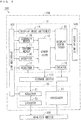
- Fig. 2 is a block diagram showing a functional configuration of the analysis control system 100 of Fig. 1 .
- the analysis control system 100 includes an operation sequence editing device 10 that performs editing processing of an operation sequence and an analysis control device 20 that performs analysis control processing of the analysis device 200 in accordance with a predetermined operation sequence.
- the operation sequence editing device 10 includes an acquirer 11, a generator 12, a display controller 13, a display mode switcher 14, an accepter 15, a contents mover 16, a column mover 17 and a creator 18.
- the CPU 101 of Fig. 1 executes the operation sequence editing program stored in the storage device 120, whereby functions of the constituent elements (11 to 18) of the operation sequence editing device 10 are implemented. Part or all of the constituent elements (11 to 18) of the operation sequence editing device 10 may be constituted by hardware such as an electronic circuit.
- the storage device 120 stores a plurality of analysis control files respectively indicating a plurality of operation sequences according to a plurality of measurement modes and a type of the sample and the like.
- the plurality of measurement modes correspond to the number of times of a dissociation operation of ions and are different from each other, and include an MS mode, an MS/MS mode and an MS" mode, for example.
- Each operation sequence indicates a plurality of steps that are sequentially performed and the contents of a plurality of setting items in each step.
- the contents of the setting item include a parameter value relating to each constituent of the analysis device 200, whether processing is performed (ON and OFF), a time point at which processing is performed and the like.
- the acquirer 11 acquires any analysis control file stored in the storage device 120 based on an operation by the user using the operation unit 130.
- the acquirer 11 may acquire an analysis control file stored in the external storage medium.
- the acquirer 11 may acquire an analysis control file stored in another storage device via the network.
- the generator 12 generates screen data for displaying the operation sequence screen in the display unit 140 based on the analysis control file acquired by the acquirer 11.
- the operation sequence screen is a screen displaying the contents of the plurality of setting items of the plurality of steps of the analysis device 200.
- the generator 12 updates the screen data based on the editing.
- the screen data generated by the generator 12 and the edited screen data are stored in the storage device 120.
- the display controller 13 allows the display unit 140 to display the operation sequence screen based on the screen data generated by the generator 12.
- the display mode switcher 14 switches a display mode of the display controller 13 between a first display mode and a second display mode based on an operation by the user using the operation unit 130.
- the operation sequence screen and the display mode of the display controller 13 will be described below.
- the user can give an instruction for editing the operation sequence by operating the operation unit 130 on the operation sequence screen displayed in the display unit 140.
- the editing of the operation sequence includes changing a parameter value in the contents of a desired setting item, changing a time point at which a desired step is performed or the like.
- the accepter 15, the contents mover 16 or the column mover 17 edits the operation sequence based on the operation by the user using the operation unit 130. Details of the editing of the operation sequence by the accepter 15, the contents mover 16 and the column mover 17 will be described below.
- the creator 18 When the operation sequence is edited, the creator 18 creates an analysis control file indicating the edited operation sequence based on the screen data that has been updated by the generator 12, and allows the storage device 120 to store the created analysis control file.
- the creator 18 may allow an external storage medium or another storage device to store the analysis control file.
- the analysis control device 20 includes an acquirer 21, an executor 22 and a processor 23.
- the CPU 101 of Fig. 1 executes the analysis control program stored in the storage device 120, whereby functions of the constituent elements (21 to 23) of the analysis control device 20 are implemented.
- Part or all of the constituent elements (21 to 23) of the analysis control device 20 may be constituted by hardware such as an electronic circuit.
- the acquirer 21 acquires any analysis control file stored in the storage device 120 based on an operation by the user using the operation unit 130.
- the acquirer 21 may acquire an analysis control file stored in an external storage medium or another storage device.
- the analysis control file acquired by the acquirer 21 may be the analysis control file that is created by the creator 18 of the operation sequence editing device 10 or may be the analysis control file that is stored in advance in the storage device 120 or the like.
- the executor 22 allows the analysis device 200 to execute mass spectrometry of the sample in accordance with the operation sequence indicated by the analysis control file acquired by the acquirer 21.
- the processor 23 acquires a digital signal indicating a result of analysis by the analysis device 200 and generates mass spectral data indicating a mass spectrum by processing the acquired digital signal. Further, the processor 23 allows the storage device 120 to store the generated mass spectral data. The processor 23 may allow an external storage medium or another storage device to store the mass spectral data.
- Fig. 3 is a diagram showing a configuration of the analysis device 200 of Fig. 1 .
- the analysis device 200 of Fig. 3 is an ion trap mass spectrometer using a matrix-assisted laser desorption ionization (MALDI) technique and an ion source, and includes an ionizer 210, an ion trap section 220, a mass spectrometer 230 and an output section 240.
- the analysis device 200 may be a mass spectrometer using a technique different from the MALDI technique, or may be an analysis device other than a mass spectrometer.
- MALDI matrix-assisted laser desorption ionization
- the ionizer 210 includes a sample plate 211, a laser emitter 212, a laser driver 213 and an extraction electrode 214.
- the sample 1 to be measured is formed on the sample plate 211.
- the laser emitter 212 is driven by the laser driver 213 and emits pulsed laser light to the sample 1.
- various components included in the sample 1 are ionized.
- the extraction electrode 214 extracts the generated ions towards the ion trap section 220 by forming a predetermined electric field.
- the ion trap section 220 includes an ion trap 221, an ion trap driver 222, a gas injector 223 and a gas driver 224.
- the ion trap 221 is constituted by a ring electrode 221a, a pair of end-cap electrodes 221b, 221c and a plurality of correction electrodes 221d. In Fig. 3 , only one correction electrode 221d is shown.
- the ring electrode 221a, the pair of end-cap electrodes 221b, 221c and the plurality of correction electrodes 221d are driven by the ion trap driver 222.
- the pair of end-cap electrodes 221b, 221c are opposite to each other with the ring electrode 221a sandwiched therebetween.
- the ring electrode 221a and the pair of end-cap electrodes 221b, 221c generate a quadrupole field for capturing ions.
- the plurality of correction electrodes 221d generate an electric field for correcting the quadrupole field generated by the ring electrode 221a and the end-cap electrodes 221b, 221c to an ideal quadrupole field.
- the ions extracted from the ionizer 210 are captured in the ion trap 221 through an opening provided in one end-cap electrode 221b.
- the gas injector 223 is driven by the gas driver 224 and arranged to be able to inject gas to the captured ions.
- the gas injector 223 injects a helium gas to the ions, thereby cooling the ions.
- a plurality of ion traps may be provided in the ion trap section 220, and a gas injector that injects an argon gas or the like may further be provided.
- the end-cap electrodes 221b, 221c add a predetermined electric field to the cooled ions.
- the ions are released from the ion trap 221 through an opening formed in the other end-cap electrode 221c and introduced into the mass spectrometer 230.
- the mass spectrometer 230 is a time-of-flight mass spectrometer.
- the ions that have been introduced into the mass spectrometer 230 fly in a flight space in the mass spectrometer 230 at a speed corresponding to a mass-to-charge ratio, and arrive at the output section 240 in an ascending order of the mass-to-charge ratio.
- the output section 240 includes a detector 241 and an A/D (Analogue/Digital) converter 242.
- the detector 241 is a photomultiplier tube, for example.
- the detector 241 detects ions that have flown in the mass spectrometer 230 and outputs an analogue signal corresponding to a detection amount.
- the A/D converter 242 converts the analogue signal that is output by the detector 241 into a digital signal and supplies the converted digital signal to the analysis control system 100.
- the above-mentioned laser driver 213, the ion trap driver 222, the gas driver 224 and the A/D converter 242 operate at predetermined time points in accordance with the operation sequence indicated by the analysis control file acquired by the analysis control system 100.
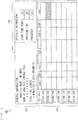
- Fig. 4 is a diagram showing one example of the operation sequence screen displayed in the display unit 140.
- the operation sequence screen 141 includes a general information display region 142, a timeline display region 143 and a detailed information setting region 144.
- the general information display region 142 an analysis mode of the analysis control file acquired by the acquirer 11 of Fig. 2 , the name of the analysis control file and a total time length of the operation sequence based on the analysis control file are displayed.
- a time axis is defined to extend in a left-and-right direction, a plurality of steps are arranged in the left-and-right direction in a chronological order, and contents of one or a plurality of setting items of each step are displayed to be arranged in an up-and-down direction. Details of the timeline display region 143 will be described below.
- the user can select the contents of a desired setting item in the timeline display region 143 by operating the operation unit 130 of Fig. 2 .
- a hatching pattern indicates the contents of the selected setting item (the contents display area 143d in which the below-mentioned "contents 27" of Fig. 5 is displayed).
- the detailed contents of the setting item selected in the timeline display region 143 are displayed in the detailed information setting region 144.
- the detailed contents of the setting item include a parameter value such as a start time point, a duration time or a frequency of the setting item of the selected step.
- the user can give an instruction for setting or changing a parameter value on the detailed information setting region 144 by operating the operation unit 130.
- the accepter 15 of Fig. 2 accepts an instruction for setting or changing a parameter value and supplies the accepted parameter value to the generator 12 of Fig. 2 .
- the operation sequence screen 141 is updated, and the operation sequence is edited.
- the operation sequence screen 141 can be displayed in either a full screen mode or a scroll display mode.
- the scale of the operation sequence screen 141 is adjusted such that the entire operation sequence screen 141 can be displayed on the display surface of the display unit 140.
- the scroll display of the operation sequence screen 141 the scale of the operation sequence screen 141 is constant.
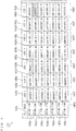
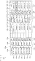
- Fig. 5 is a diagram showing the details of the timeline display region 143 of Fig. 4 .
- a time-axis scale 143a extending in the left-and-right direction
- a plurality of step display areas 143b a plurality of item display areas 143c
- a plurality of contents display areas 143d a time-axis switch button 143e are displayed in the timeline display region 143.
- the time-axis scale 143a is displayed during the first display mode and not displayed during the second display mode. The display mode will be described below.
- the plurality of step display areas 143b are arranged along the time axis.
- a step identification information piece for identifying a step is displayed.
- the plurality of step display areas 143b are displayed to correspond to the time points on the time-axis scale 143a.
- the "step 1" to the "step 7" are respectively displayed in the plurality of step display areas 143b as the step identification information pieces.
- the specific step identification information pieces are "preparation", "laser emission”, “ion capture", "cooling” or the like.
- the timeline display region 143 of Fig. 5 is displayed in the scroll display, and the step display areas 143b of the steps that come later than the "step 7" are not displayed.
- the plurality of item display areas 143c are arranged in the up-and-down direction.
- a setting item identification information piece for identifying a setting item is displayed in each item display area 143c.
- the "setting item 1" to the “setting item 7" are respectively displayed in the plurality of item display areas 143c as the setting item identification information pieces.
- Specific setting item identification information pieces are a "ring electrode”, an "end-cap electrode”, a “correction electrode”, "laser”, a “helium gas”, an “argon gas”, "A/D conversion” or the like.
- the plurality of contents display areas 143d are arranged in the up-and-down direction for each step.
- the contents of a setting item are displayed.
- the "contents 11" to the “contents 17" are respectively displayed in the plurality of contents display areas 143d that correspond to the "setting item 1" and are arranged in a chronological order as the contents of the setting items.
- the similar contents of the setting items such as the "contents 21" to the “contents 77" are also displayed in the plurality of contents display areas 143d corresponding to the "setting item 2" to the "setting item 7".
- the specific contents of the setting items are "normal", “scan", “trigger ON”, “no processing” or the like.
- the change of the frequency of an RF (radio frequency) voltage added to the "ring electrode” is further indicated by a dotted line.
- the contents of the setting item may include an index indicating a parameter value.
- a step display area 143b and a plurality of contents display areas 143d corresponding to each step constitute a step display column 143f.
- the user can give an instruction for switching the display mode to the display mode switcher 14 of Fig. 2 every time the user operates the time-axis switch button 143e using the operation unit 130.
- the display mode switcher 14 switches the display mode of the display controller 13 of Fig. 2 between the first display mode and the second display mode every time the display mode switcher 14 receives an instruction for switching the display mode.
- each of the plurality of step display columns 143f is displayed to have a length corresponding to an actual time length required for each step in the time-axis direction as shown in the example of Fig. 5 .
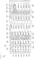
- Fig. 6 is a diagram showing the details of the timeline display region 143 in the second display mode.
- the plurality of step display columns 143f are displayed to have the similar lengths in the time-axis direction in the second display mode.
- the time-axis scale 143a is not shown.
- the user can easily identify the chronological order of the plurality of steps.
- Fig. 7 is a diagram showing one example of the editing of the operation sequence.
- the user selects the contents display area 143d in which the "contents 27" is displayed and performs an operation of moving the "contents 27" to a contents display area 143d in another step using the operation unit 130.
- the contents mover 16 of Fig. 2 moves the contents of the selected contents display area 143d to another contents display area 143d based on the operation by the user.
- the contents of the contents display areas 143d that have been present between the selected source contents display area 143d and the selected destination contents display area 143d move towards the step of the selected source contents display area 143d.
- the contents of the selected source contents display area 143d may be rewritten by the contents of the destination contents display area 143d, or may be copied to the destination contents display area 143d.
- the generator 12 of Fig. 2 updates the screen data based on the movement of the contents by the contents mover 16.
- Fig. 8 is a diagram showing another example of the editing of the operation sequence.
- the user selects the step display area 143b in which the "step 3" is displayed using the operation unit 130 and performs an operation of moving the "step 3" to a step display column 143f of another step.
- the column mover 17 of Fig. 2 moves the step identification information piece and the contents of the selected step display column 143f to another step display column 143f based on the operation by the user.
- step identification information pieces and the contents in the step display columns 143f that have been present between the selected source step display column 143f and the selected destination step display column 143f move towards the step of the selected source step display column 143f.
- the step identification information piece and the contents in the selected source step display column 143f may be rewritten by the step identification information piece and the contents in the destination step display column 143f, or may be copied to the destination step display column 143f.
- the generator 12 updates the screen data based on the movement of the contents by the column mover 17.
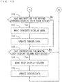
- Figs. 9 and 10 are flow charts showing the algorithm of the editing processing executed by the operation sequence editing program. Further, the acquirer 11 first determines whether an analysis control file has been designated (step S1). The user can designate a desired analysis control file stored in the storage device 120 or the like by operating the operation unit 130. When an analysis control file is not designated, the acquirer 11 proceeds to the step S5. When an analysis control file is designated, the acquirer 11 acquires the designated analysis control file from the storage device 120 or the like (step S2).
- the generator 12 generates the screen data based on the analysis control file acquired in the step S2 (step S3).
- the display controller 13 allows the display unit 140 to display the operation sequence screen based on the screen data generated in the step S3 (step S4) and proceeds to the step S5.
- the operation sequence screen is continuously displayed in the display unit 140. Further, when the screen data is updated, the operation sequence screen is displayed in the display unit 140 based on the updated screen data.
- step S5 the display controller 13 determines whether an instruction for ending the editing processing has been given (step S5).
- the user can give an instruction for ending the editing processing to the display controller 13 by operating the operation unit 130.
- the display mode switcher 14 determines whether the time-axis switch button 143e has been operated (step S6).
- the display mode switcher 14 proceeds to the step S8.
- the first display mode is selected as the display mode of the display controller 13 in an initial state.
- the display mode switcher 14 switches the display mode of the display controller 13 between the first display mode and the second display mode (step S7) and proceeds to the step S8.
- the accepter 15 determines whether an instruction for setting or changing the contents of a setting item has been given (step S8). For example, the user can set or change a parameter value corresponding to a desired contents display area 143d in the detailed information setting region 144 by operating the operation unit 130. Further, the user can set the contents such as a parameter value, whether processing is performed or a time point at which the processing is performed in a desired contents display area 143d or change the contents displayed in the contents display area 143d by operating the operation unit 130.
- the accepter 15 proceeds to the step S11.
- the generator 12 updates the screen data based on the contents accepted by the accepter 15 (step S9) and proceeds to the step S10.
- the contents mover 16 determines whether an instruction for moving any contents display area 143d has been given (step S10).
- the user can give an instruction for moving the desired contents display area 143d in the timeline display region 143 by operating the operation unit 130.
- the contents mover 16 proceeds to the step S13.
- the contents mover 16 moves the contents of the selected contents display area 143d to another contents display area 143d based on the instruction (step S11).
- the generator 12 updates the screen data based on the contents display area 143d that has been moved by the contents mover 16 (step S12) and proceeds to the step S13.
- the column mover 17 determines whether an instruction for moving any step display column 143f has been given (step S13).
- the user can give an instruction for moving a desired step display column 143f in the timeline display region 143 by operating the operation unit 130.
- the column mover 17 returns to the step S5.
- the column mover 17 moves the selected step display column 143f to another step display column 143f based on the instruction (step S14).
- the generator 12 updates the screen data based on the step display column 143f that has been moved by the column mover 17 (step S15) and returns to the step S5.
- step S5 when an instruction for ending the editing processing is given, the display controller 13 determines whether the screen data has been updated (step S16). When the screen data has not been updated, the display controller 13 ends the editing processing.
- the creator 18 updates the analysis control file acquired in the step S2 based on the screen data that is updated in the step S9, S12 or S15 (step S17). Further, the creator 18 allows the storage device 120 or the like to store the analysis control file that is updated in the step S17 (step S18) and ends the editing processing.
- part of the processing may be performed at another time point.
- any of a set of the steps S6 and S7, a set of the steps S8 and S9, a set of the steps S10 to S12 and a set of the steps S13 to S15 may be performed first.
- the operation sequence screen 141 is displayed in the display unit 140.
- the plurality of step display areas 143b in which the plurality of step identification information pieces for identifying the plurality of steps of the analysis device 200 are arranged in the time-axis direction in a chronological order and arranged along the time-axis.
- the plurality of item display areas 143c displaying the plurality of item identification information pieces for identifying the plurality of setting items of each step are arranged in the direction that intersects with the time-axis direction.
- the plurality of contents display areas 143d in which the contents of the plurality of setting items are displayed are arranged in the direction that intersects with the time-axis direction for each step.
- a step display column 143f is constituted by a step display area 143b corresponding to each step and a plurality of contents display areas 143d.
- the user can easily identify the chronological order of the plurality of steps and the contents of the setting item of each step by viewing the operation sequence screen 141.
- the detailed setting contents of the entire operation sequence of the analysis device 200 can be easily identified.
- the user can easily identify each step and each setting item and can easily identify the contents of each setting item, and the correspondence relationship between the step and the setting item.
- the user can easily identify the contents of the setting item of each step by viewing the step display column 143f.
Landscapes
- Engineering & Computer Science (AREA)
- Theoretical Computer Science (AREA)
- General Engineering & Computer Science (AREA)
- Physics & Mathematics (AREA)
- General Physics & Mathematics (AREA)
- Human Computer Interaction (AREA)
- Chemical & Material Sciences (AREA)
- Analytical Chemistry (AREA)
- Life Sciences & Earth Sciences (AREA)
- Health & Medical Sciences (AREA)
- Biochemistry (AREA)
- General Health & Medical Sciences (AREA)
- Immunology (AREA)
- Pathology (AREA)
- Other Investigation Or Analysis Of Materials By Electrical Means (AREA)
- Electron Tubes For Measurement (AREA)
- User Interface Of Digital Computer (AREA)
Applications Claiming Priority (1)
| Application Number | Priority Date | Filing Date | Title |
|---|---|---|---|
| JP2017153687A JP6881142B2 (ja) | 2017-08-08 | 2017-08-08 | 動作シーケンス編集装置、分析制御システム、分析システムおよび動作シーケンス編集方法 |
Publications (1)
| Publication Number | Publication Date |
|---|---|
| EP3442002A1 true EP3442002A1 (de) | 2019-02-13 |
Family
ID=63363848
Family Applications (1)
| Application Number | Title | Priority Date | Filing Date |
|---|---|---|---|
| EP18187743.2A Withdrawn EP3442002A1 (de) | 2017-08-08 | 2018-08-07 | Operationssequenzbearbeitungsvorrichtung, analysesteuerungssystem, analysesystem und betriebssequenzbearbeitungsverfahren |
Country Status (3)
| Country | Link |
|---|---|
| US (1) | US20190050139A1 (de) |
| EP (1) | EP3442002A1 (de) |
| JP (1) | JP6881142B2 (de) |
Families Citing this family (1)
| Publication number | Priority date | Publication date | Assignee | Title |
|---|---|---|---|---|
| CN112291411A (zh) * | 2019-07-27 | 2021-01-29 | 华为技术有限公司 | 推荐操作序列的方法、终端及计算机可读介质 |
Citations (3)
| Publication number | Priority date | Publication date | Assignee | Title |
|---|---|---|---|---|
| EP2634792A2 (de) * | 2012-03-02 | 2013-09-04 | Hitachi High-Technologies Corporation | Massenspektrometriesystem |
| JP2015185307A (ja) | 2014-03-24 | 2015-10-22 | 株式会社島津製作所 | イオントラップ質量分析装置及び該装置を用いた質量分析方法 |
| EP3015979A1 (de) * | 2014-10-29 | 2016-05-04 | Omron Corporation | Informationsverarbeitungsvorrichtung, informationsverarbeitungsverfahren, informationsverarbeitungsprogramm und speichermedium |
Family Cites Families (4)
| Publication number | Priority date | Publication date | Assignee | Title |
|---|---|---|---|---|
| JP2004349139A (ja) * | 2003-05-23 | 2004-12-09 | Hitachi High-Technologies Corp | イオントラップ質量分析装置 |
| JP2006099622A (ja) * | 2004-09-30 | 2006-04-13 | Dkk Toa Corp | シーケンスプログラム作成方法、作成システム及びシーケンス制御システム |
| US20120305762A1 (en) * | 2010-03-24 | 2012-12-06 | Akihito Kaneko | Ion isolation method and mass spectrometer |
| JP6592353B2 (ja) * | 2015-12-17 | 2019-10-16 | 株式会社日立製作所 | 磁気共鳴イメージング装置、パルスシーケンス生成プログラム、パルスシーケンス生成方法、および、パルスシーケンス生成装置 |
-
2017
- 2017-08-08 JP JP2017153687A patent/JP6881142B2/ja not_active Expired - Fee Related
-
2018
- 2018-08-02 US US16/052,755 patent/US20190050139A1/en not_active Abandoned
- 2018-08-07 EP EP18187743.2A patent/EP3442002A1/de not_active Withdrawn
Patent Citations (3)
| Publication number | Priority date | Publication date | Assignee | Title |
|---|---|---|---|---|
| EP2634792A2 (de) * | 2012-03-02 | 2013-09-04 | Hitachi High-Technologies Corporation | Massenspektrometriesystem |
| JP2015185307A (ja) | 2014-03-24 | 2015-10-22 | 株式会社島津製作所 | イオントラップ質量分析装置及び該装置を用いた質量分析方法 |
| EP3015979A1 (de) * | 2014-10-29 | 2016-05-04 | Omron Corporation | Informationsverarbeitungsvorrichtung, informationsverarbeitungsverfahren, informationsverarbeitungsprogramm und speichermedium |
Non-Patent Citations (3)
| Title |
|---|
| SHIMADZU CORPORATION: "Shimadzu LCMSsolution for LCMS-2010 / LCMS-QP8000[alpha] Operation Guide", 1 January 2003 (2003-01-01), pages 1 - 66, XP055350892, Retrieved from the Internet <URL:http://www.chem.pitt.edu/sites/default/files/users/dragon3/LCMSQuickGuide_Shimadzu.pdf> [retrieved on 20170302] * |
| UNKNOWN: "Chapter 4.8 from Micromass Quattro Ultima Pt Mass Spectrometer Operator Guide", 1 January 2003 (2003-01-01), XP002787009, Retrieved from the Internet <URL:http://www.waters.com/webassets/cms/support/docs/quattro_ultima_pt_guide_reva.pdf> [retrieved on 20181203] * |
| UNKNOWN: "Software for Hiden Mass Spectrometers Including application specific software packages for: Quantitative gas analysis Evolved gas analysis - TA-MS UHV -TPD Gas Analysis, Thermal Analysis and Residual Gas Analysis", 16 June 2017 (2017-06-16), XP055528943, Retrieved from the Internet <URL:https://www.hidenanalytical.com/wp-content/uploads/2016/07/Hiden_MS_Software_new.pdf> [retrieved on 20181130] * |
Also Published As
| Publication number | Publication date |
|---|---|
| JP2019032245A (ja) | 2019-02-28 |
| JP6881142B2 (ja) | 2021-06-02 |
| US20190050139A1 (en) | 2019-02-14 |
Similar Documents
| Publication | Publication Date | Title |
|---|---|---|
| JP6597909B2 (ja) | 質量分析データ処理装置 | |
| JP4324702B2 (ja) | 質量分析方法 | |
| US20150160162A1 (en) | User interfaces, systems and methods for displaying multi-dimensional data for ion mobility spectrometry-mass spectrometry | |
| US20030213902A1 (en) | Method and apparatus for analyzing mass spectrum | |
| CN112730572B (zh) | 用于调谐质谱仪的方法和系统 | |
| US20230366863A1 (en) | Automated Modeling of LC Peak Shape | |
| US10928358B2 (en) | Mass spectrometer using judgement condition for display | |
| JPWO2007060760A1 (ja) | 質量分析装置 | |
| US20170299550A1 (en) | Wideband isolation directed by ion mobility separation for analyzing compounds | |
| EP3442002A1 (de) | Operationssequenzbearbeitungsvorrichtung, analysesteuerungssystem, analysesystem und betriebssequenzbearbeitungsverfahren | |
| JP6627968B2 (ja) | クロマトグラフ質量分析装置 | |
| JPH095300A (ja) | 液体クロマトグラフ質量分析装置 | |
| CN108027346B (zh) | 质谱分析装置、质谱分析方法以及质谱分析用程序 | |
| JP6718712B2 (ja) | 質量分析装置 | |
| CN115461838A (zh) | 激光解吸离子化质量分析装置及激光功率调整方法 | |
| US11513105B2 (en) | Composition estimating apparatus and method | |
| JP6160471B2 (ja) | 飛行時間型質量分析装置及び該装置を用いた質量分析方法 | |
| JP4678438B2 (ja) | 質量分析装置用データ処理装置 | |
| JP2019164919A (ja) | 質量分析装置 | |
| US11527393B2 (en) | Spectrum calculation processing device, spectrum calculation processing method, ion trap mass spectrometry system, ion trap mass spectrometry method and non-transitory computer readable medium storing spectrum calculation processing program | |
| JP6649642B2 (ja) | 質量分析装置及び質量分析装置用プログラム | |
| EP4471825A1 (de) | Erfassungsplanung und lastausgleich für gezielte massenspektrometrie | |
| JP6477332B2 (ja) | 質量分析方法、質量分析装置、及び質量分析用プログラム | |
| JPWO2017179096A1 (ja) | 質量分析装置及び質量分析方法 | |
| JPH04296434A (ja) | クロマトグラフ/質量分析装置 |
Legal Events
| Date | Code | Title | Description |
|---|---|---|---|
| PUAI | Public reference made under article 153(3) epc to a published international application that has entered the european phase |
Free format text: ORIGINAL CODE: 0009012 |
|
| STAA | Information on the status of an ep patent application or granted ep patent |
Free format text: STATUS: REQUEST FOR EXAMINATION WAS MADE |
|
| 17P | Request for examination filed |
Effective date: 20180807 |
|
| AK | Designated contracting states |
Kind code of ref document: A1 Designated state(s): AL AT BE BG CH CY CZ DE DK EE ES FI FR GB GR HR HU IE IS IT LI LT LU LV MC MK MT NL NO PL PT RO RS SE SI SK SM TR |
|
| AX | Request for extension of the european patent |
Extension state: BA ME |
|
| STAA | Information on the status of an ep patent application or granted ep patent |
Free format text: STATUS: THE APPLICATION HAS BEEN WITHDRAWN |
|
| 18W | Application withdrawn |
Effective date: 20200826 |