EP3441662A1 - Anschlussstutzen - Google Patents
Anschlussstutzen Download PDFInfo
- Publication number
- EP3441662A1 EP3441662A1 EP18186264.0A EP18186264A EP3441662A1 EP 3441662 A1 EP3441662 A1 EP 3441662A1 EP 18186264 A EP18186264 A EP 18186264A EP 3441662 A1 EP3441662 A1 EP 3441662A1
- Authority
- EP
- European Patent Office
- Prior art keywords
- connecting piece
- spring
- rotary tool
- transverse opening
- extensions
- Prior art date
- Legal status (The legal status is an assumption and is not a legal conclusion. Google has not performed a legal analysis and makes no representation as to the accuracy of the status listed.)
- Granted
Links
Images


Classifications
-
- F—MECHANICAL ENGINEERING; LIGHTING; HEATING; WEAPONS; BLASTING
- F16—ENGINEERING ELEMENTS AND UNITS; GENERAL MEASURES FOR PRODUCING AND MAINTAINING EFFECTIVE FUNCTIONING OF MACHINES OR INSTALLATIONS; THERMAL INSULATION IN GENERAL
- F16L—PIPES; JOINTS OR FITTINGS FOR PIPES; SUPPORTS FOR PIPES, CABLES OR PROTECTIVE TUBING; MEANS FOR THERMAL INSULATION IN GENERAL
- F16L41/00—Branching pipes; Joining pipes to walls
- F16L41/08—Joining pipes to walls or pipes, the joined pipe axis being perpendicular to the plane of a wall or to the axis of another pipe
- F16L41/088—Joining pipes to walls or pipes, the joined pipe axis being perpendicular to the plane of a wall or to the axis of another pipe fixed using an elastic grommet between the extremity of the tube and the wall
-
- F—MECHANICAL ENGINEERING; LIGHTING; HEATING; WEAPONS; BLASTING
- F16—ENGINEERING ELEMENTS AND UNITS; GENERAL MEASURES FOR PRODUCING AND MAINTAINING EFFECTIVE FUNCTIONING OF MACHINES OR INSTALLATIONS; THERMAL INSULATION IN GENERAL
- F16B—DEVICES FOR FASTENING OR SECURING CONSTRUCTIONAL ELEMENTS OR MACHINE PARTS TOGETHER, e.g. NAILS, BOLTS, CIRCLIPS, CLAMPS, CLIPS OR WEDGES; JOINTS OR JOINTING
- F16B5/00—Joining sheets or plates, e.g. panels, to one another or to strips or bars parallel to them
- F16B5/06—Joining sheets or plates, e.g. panels, to one another or to strips or bars parallel to them by means of clamps or clips
- F16B5/0607—Joining sheets or plates, e.g. panels, to one another or to strips or bars parallel to them by means of clamps or clips joining sheets or plates to each other
- F16B5/0621—Joining sheets or plates, e.g. panels, to one another or to strips or bars parallel to them by means of clamps or clips joining sheets or plates to each other in parallel relationship
- F16B5/0664—Joining sheets or plates, e.g. panels, to one another or to strips or bars parallel to them by means of clamps or clips joining sheets or plates to each other in parallel relationship at least one of the sheets or plates having integrally formed or integrally connected snap-in-features
-
- E—FIXED CONSTRUCTIONS
- E03—WATER SUPPLY; SEWERAGE
- E03F—SEWERS; CESSPOOLS
- E03F3/00—Sewer pipe-line systems
- E03F3/04—Pipes or fittings specially adapted to sewers
-
- F—MECHANICAL ENGINEERING; LIGHTING; HEATING; WEAPONS; BLASTING
- F16—ENGINEERING ELEMENTS AND UNITS; GENERAL MEASURES FOR PRODUCING AND MAINTAINING EFFECTIVE FUNCTIONING OF MACHINES OR INSTALLATIONS; THERMAL INSULATION IN GENERAL
- F16B—DEVICES FOR FASTENING OR SECURING CONSTRUCTIONAL ELEMENTS OR MACHINE PARTS TOGETHER, e.g. NAILS, BOLTS, CIRCLIPS, CLAMPS, CLIPS OR WEDGES; JOINTS OR JOINTING
- F16B5/00—Joining sheets or plates, e.g. panels, to one another or to strips or bars parallel to them
- F16B5/06—Joining sheets or plates, e.g. panels, to one another or to strips or bars parallel to them by means of clamps or clips
- F16B5/0607—Joining sheets or plates, e.g. panels, to one another or to strips or bars parallel to them by means of clamps or clips joining sheets or plates to each other
- F16B5/0621—Joining sheets or plates, e.g. panels, to one another or to strips or bars parallel to them by means of clamps or clips joining sheets or plates to each other in parallel relationship
- F16B5/0642—Joining sheets or plates, e.g. panels, to one another or to strips or bars parallel to them by means of clamps or clips joining sheets or plates to each other in parallel relationship the plates being arranged one on top of the other and in full close contact with each other
-
- F—MECHANICAL ENGINEERING; LIGHTING; HEATING; WEAPONS; BLASTING
- F16—ENGINEERING ELEMENTS AND UNITS; GENERAL MEASURES FOR PRODUCING AND MAINTAINING EFFECTIVE FUNCTIONING OF MACHINES OR INSTALLATIONS; THERMAL INSULATION IN GENERAL
- F16B—DEVICES FOR FASTENING OR SECURING CONSTRUCTIONAL ELEMENTS OR MACHINE PARTS TOGETHER, e.g. NAILS, BOLTS, CIRCLIPS, CLAMPS, CLIPS OR WEDGES; JOINTS OR JOINTING
- F16B5/00—Joining sheets or plates, e.g. panels, to one another or to strips or bars parallel to them
- F16B5/07—Joining sheets or plates, e.g. panels, to one another or to strips or bars parallel to them by means of multiple interengaging protrusions on the surfaces, e.g. hooks, coils
Definitions
- the invention relates to a connection piece for insertion into an elastomer insert for the formation of a connection device.
- connection device comprising an elastomer insert and a connecting piece.
- the invention relates to a Fluidleit-, recording and storage system with such a connection device.
- connection device comprising an elastomeric insert and a connecting piece is from the DE 20 2006 005 685 U1 known.
- a connection device is suitable for fluid-tightly connecting a secondary pipeline to a main line, a shaft or a transverse opening in a wall.
- Such connection devices must be safely installable and durable and have a high fluid tightness.
- the elastomer insert is first inserted into the transverse opening of a main line, a shaft or a wall, and then screwed the connection piece in the elastomeric insert to press the outer surface of the elastomer insert as large as possible to the reveal of the transverse opening.
- connection piece For screwing an internal thread is formed on the inside of the hollow plug-shaped elastomer insert, corresponding to the outside of the connecting piece an external thread.
- a rotary tool is generally used, which interacts with extensions on the connection piece and thus enables engagement and rotation of the connection piece.
- Another object of the invention is to provide a connection device with such an improved connection piece.
- connection piece according to claim 1 The first object is achieved by the connection piece according to claim 1.
- connection piece for insertion into an elastomeric insert to form a connection device for a secondary pipe in combination with a transverse opening in a main pipe, in a shaft or in a wall wherein the outside of the elastomeric insert to the Transverse opening is adapted and the inside of the elastomeric insert has a conical screw portion
- the connecting piece has an engagement end, a conical central part with external thread, a receiving portion and a drive end with projections, is formed such that at least one spring extension is formed at the drive end, the suitable is to set a rotary tool for rotation of the connecting piece under spring force.
- connection stub which allows the rotary tool, which is necessary for rotating the connecting piece in the elastomeric insert to form the connecting device, is securely fixed, thus can not slip and thus the risk of damaging the connecting piece or the risk of injury to the installing personnel is excluded or considerably minimized.
- the at least one spring extension is formed integrally with the connecting piece.
- integrally forming the at least one spring extension of the connecting piece with the connecting piece on the one hand, a simplified production of such a connecting piece according to the invention becomes possible since the spring extension can be formed in a mold, for example an injection molding tool, together with the connecting piece in a molding process. Furthermore, so that a very durable and stable spring extension is created, which hardly tends that he kinks, for example, by overloading or breaks off.
- two or four spring extensions are formed.
- two or four spring extensions can be formed next to these extensions on the connecting piece, which has a drive end, on which extensions are arranged. This makes it particularly easy to set the rotary tool, which is necessary for rotating the connecting piece in the elastomeric insert to form the connecting device, in a particularly secure manner.
- two spring extensions are formed, which are diametrically opposed.
- the rotary tool for rotating the connecting piece can be particularly easily determined by spring force.
- a spring element is formed on the spring extension.
- a spring element may for example be a tunnel spring element or a bow spring element.
- a spring element in the form of a bow spring element or in the form of a bow spring element is particularly suitable for fixing the rotary tool for rotating the connecting piece under spring force. This slippage of the turning tool when pressing is effectively prevented.
- the connecting piece of the present invention can be designed with great advantage in such a way that it consists of a polymer material or contains a polymer material, wherein the polymer material is preferably a thermoplastic, and more preferably a polyolefin, such as a polypropylene or a polyethylene or a polybutylene, or a Copolymer of the above, or a crosslinked polyolefin, in particular a crosslinked polyethylene, or a polyvinyl chloride, or a polyurethane.
- the polymer material is preferably a thermoplastic, and more preferably a polyolefin, such as a polypropylene or a polyethylene or a polybutylene, or a Copolymer of the above, or a crosslinked polyolefin, in particular a crosslinked polyethylene, or a polyvinyl chloride, or a polyurethane.
- Such polymeric materials are durable, inert, stable, lightweight, easy to handle, easy to install, and cost-effective to provide. In particular, in this way it is very easy to form the connection piece from the polymer material.
- such a connecting piece according to the invention can be produced by means of a polymer molding method.
- a connection piece can be easily manufactured.
- connection piece is produced using a generative production method, for example by a 3-D printing method.
- a data processing machine-readable three-dimensional model can advantageously be used for the production.
- the invention also encompasses a method for producing a data processing machine readable three-dimensional model for use in a production method for a connecting piece.
- the method also includes, in particular, the input of data representing a connecting piece into a data processing machine and the use of the data to represent a spigot as a three-dimensional model, the three-dimensional model is suitable for use in the production of a connecting piece.
- the manufacturing process may include a generative powder bed process, in particular selective laser melting (SLM), selective laser sintering (SLS), selective heat sintering (SHS), electron beam melting (EBM) or powder material consolidation by binder (binder jetting).
- SLM selective laser melting
- SLS selective laser sintering
- SHS selective heat sintering
- EBM electron beam melting
- binder jetting powder material consolidation by binder
- the manufacturing process can be a generative free-space process, in particular, hardfacing, wax deposition modeling (WDM), contour crafting, metal powder application (MPA), plastic powder coating, cold gas spraying, electron beam welding (EBW) or melt coating techniques such as fused deposition Modeling (FDM) or Fused Filament Fabrication (FFF).
- WDM wax deposition modeling
- MPA metal powder application
- EBW electron beam welding
- FDM fused deposition Modeling
- FFF Fused Filament Fabrication
- the manufacturing process may include a generative liquid material process, particularly stereolithography (SLA), Digital Light Processing (DLP), Multi Jet Modeling (MJM), Polyjet Modeling or Liquid Composite Molding (LCM).
- the manufacturing method may include other generative layer building methods, in particular Laminated Object Modeling (LOM), 3D screen printing or light-controlled electrophoretic deposition.
- LOM Laminated Object Modeling
- connection device for a secondary pipeline in combination with a transverse opening in a main pipeline, in a shaft or in a wall is then upgraded in particular if it is provided that these have a hollow-plug-shaped elastomer insert and a connecting piece, as described above.
- the last object of the present invention to provide a Fluidleit-, recording and storage system, learns its solution in claim. 8
- the fluid conducting, receiving and storing system comprises a secondary pipeline, a main pipeline and / or a shaft and / or a wall, and a connection device for a secondary pipeline in combination with a transverse opening in a main pipeline, in a shaft or in a wall, as described above.
- FIG. 1 is a schematic side view of a connecting piece 1 is shown.
- the connecting piece 1 has an engagement end 1a, with the first he is introduced into the elastomeric insert, not shown here.
- a conical part 1b At the engagement end 1a of the connecting piece 1 is followed by a conical part 1b, on which an external thread 4 is formed.
- a receiving portion 1c connects, which is used as a plug-in portion 2, to insert a not shown here side pipe in the connecting piece 1 in a fluid-tight manner.
- a drive end connects to 1d, which has an end edge 3, on the extensions 5 and at least one spring extension 6 are formed.
- the extensions 5 and the at least one spring extension 6 are rounded at their edges, so that a simpler placement of the rotary tool 13 is made possible by this measure.
- Fig. 2 is shown in a schematic side view of a spring extension 6 in a first embodiment.
- the spring extension 6 at the end edge 3 of the connecting piece 1 has a central portion 7, which protrudes from the end edge 3 of the connecting piece 1 approximately vertically upwards.
- the central portion 7 of the spring extension 6 is flanked by two opposing spring elements 8, which are formed as bow spring elements 8a edge.
- Fig. 3 is shown in a schematic side view of a spring extension 6 in a second embodiment.
- the spring extension 6 at the end edge 3 of the connection piece 1 is approximately vertical upward from the end edge 3.
- the spring extension 6 in the second embodiment has a central portion 10, which has a free space 9 in the form of an opening at the edge opposite each other, so that two spring elements 11 are formed in the form of bow spring elements 11a.
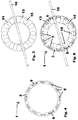
- FIG. 4 is a schematic plan view of a connecting piece 1 shown.
- extensions 5 and spring extensions 6 are formed at the end edge 3 of the connecting piece 1 at the end edge 3 of the connecting piece 1 at the end edge 3 of the connecting piece 1 .
- ten extensions 5 and two spring extensions 6 are formed on the end edge 3 of the connecting piece 1.
- the two spring extensions 6 are arranged such that they are diametrically opposed.
- Each extension 5 or each spring extension 6 has to its immediate neighbors in each case the same distance, so that all extensions 5 and spring extensions 6 are arranged in a uniform distribution at the end edge 3 of the connecting piece 1.
- FIG. 5 is a schematic plan view of a rotary tool 13 is shown.
- the rotary tool 13 comprises a receiving portion 14, which is formed for example in the form of a flat metal sheet.
- openings 15 are arranged.
- the apertures 15 on the receiving portion 14 of the rotary tool 13 correspond in their number and size with the extensions 5 and spring extensions 6 on the connecting piece 1.
- Fig. 5 formed on the rotary tool 13 twelve openings 15.
- the openings 15 have an approximately trapezoidal shape and thus allow different diameters of connecting piece 1 to drive.
- the rotary tool 13 has a handle 16, with which the rotary tool 13 is drivable.
- Fig. 6 is shown in a plan, as the rotary tool 13 is placed on the connection piece 1.
- Fig. 7 is a schematic side view of a spring extension 6, on which a rotary tool 13 is placed in a first state.
- the rotary tool 13 is positioned with its opening 15 which is formed on the receiving portion 14 such that the spring extension 6 is aligned with the opening 15 of the rotary tool 13.
- Fig. 8 is a schematic side view of a spring extension 6, on which a rotary tool 13 is placed in a second state shown.
- the rotary tool 13 has been moved in the second state in the direction of the end edge 3 of the connecting piece 1, so that the edge of the receiving portion 14 at the opening 15 of the rotary tool 13 comes into contact with the spring element 8, which is in the form of a bow spring element 8a.
- the spring elements 8 which are formed as bow spring elements 8 a, bent by the edge of the receiving portion 14 at the opening 15 of the rotary tool 13 a small distance in the direction of the central portion 7, wherein the Free space 9 between the central portion 7 of the spring extension 6 and the spring element 8 is reduced.
- FIG. 9 a schematic side view of a spring extension 6, on which a rotary tool 13 is placed, shown in a third state.
- the receiving portion 14 of the rotary tool 13 is fixed by spring force at the end edge 3 of the connecting piece 1, so that the connecting piece 1 in a secure manner in the elastomer insert not shown here by means of the rotary tool 13 is screwed.
Landscapes
- Engineering & Computer Science (AREA)
- General Engineering & Computer Science (AREA)
- Mechanical Engineering (AREA)
- Quick-Acting Or Multi-Walled Pipe Joints (AREA)
Abstract
Description
- Die Erfindung betrifft einen Anschlussstutzen zum Einsetzen in einen Elastomereinsatz für die Bildung einer Anschlussvorrichtung.
- Des Weiteren betrifft die Erfindung eine Anschlussvorrichtung, die einen Elastomereinsatz und einen Anschlussstutzen umfasst.
- Schließlich betrifft die Erfindung ein Fluidleit-, -aufnahme- und -speichersystem mit einer solchen Anschlussvorrichtung.
- Eine gattungsgemäße Anschlussvorrichtung, die einen Elastomereinsatz und einen Anschlussstutzen umfasst ist aus der
DE 20 2006 005 685 U1 bekannt.
Eine solche Anschlussvorrichtung ist geeignet, eine Nebenrohrleitung fluiddicht an eine Hauptleitung, einen Schacht oder eine Queröffnung in einer Wand anzuschließen. Derartige Anschlussvorrichtungen müssen sicher installierbar und dauerhaft sein und eine hohe Fluiddichtheit aufweisen. - Zur Herstellung der Anschlussvorrichtung wird zunächst der Elastomereinsatz in die Queröffnung einer Hauptleitung, eines Schachtes oder einer Wand eingesetzt, und anschließend der Anschlussstutzen in den Elastomereinsatz eingeschraubt, um die Außenfläche des Elastomereinsatzes möglichst großflächig an die Laibung der Queröffnung anzupressen.
- Zum Einschrauben ist an der Innenseite des hohlstopfenförmig ausgebildeten Elastomereinsatzes ein Innengewinde ausgebildet, entsprechend an der Außenseite des Anschlussstutzens ein Außengewinde. Zum Einschrauben des Anschlussstutzens in den Elastomereinsatz zur Bildung der Anschlussvorrichtung wird im Allgemeinen ein Drehwerkzeug benutzt, welches mit Fortsätzen am Anschlussstutzen interagiert und so ein Eingreifen und Drehen des Anschlussstutzens ermöglicht.
- Es hat sich herausgestellt, dass diese Lösung verschiedene Nachteile mit sich bringt, so kann das Drehwerkzeug vom Anschlussstutzen abrutschen, sodass zum einen der Anschlussstutzen oder die Fortsätze am Anschlussstutzen beschädigt werden können, zum anderen kann es auch zu einer Verletzung der Person kommen, die die Anschlussvorrichtung installiert.
- Weiterhin ist nach dem Abrutschen eine Neupositionierung des Drehwerkzeugs am Anschlussstutzen notwendig, um diesen dann weiter einzudrehen, was mit einem Zeitverlust bei der Installation der Anschlussvorrichtung einhergeht.
- Hier setzt die Erfindung ein, der die Aufgabe zugrunde liegt, einen verbesserten Anschlussstutzen bereitzustellen, der die vorstehend genannten Nachteile der Technik überwindet.
- Eine weitere Aufgabe der Erfindung ist es, eine Anschlussvorrichtung mit einem solchen verbesserten Anschlussstutzen anzugeben.
- Schließlich ist es noch Aufgabe der vorliegenden Erfindung, ein Fluidleit-, -aufnahme- und -speichersystem bereitzustellen, welches eine solche Anschlussvorrichtung umfasst.
- Die erste gestellte Aufgabe wird durch den Anschlussstutzen gemäß Anspruch 1 gelöst.
- Es ist im Rahmen der vorliegenden Erfindung vorgesehen, dass der Anschlussstutzen zum Einsetzen in einen Elastomereinsatz zur Bildung einer Anschlussvorrichtung für eine Neben-rohrleitung in Kombination mit einer Queröffnung in einer Hauptrohrleitung, in einem Schacht oder in einer Wand, wobei die Außenseite des Elastomereinsatzes an die Queröffnung angepasst ist und die Innenseite des Elastomereinsatzes einen konischen Schraubbereich aufweist, und wobei der Anschlussstutzen ein Eingriffsende, einen konischen Mittelteil mit Außengewinde, einen Aufnahmeabschnitt und ein Antriebsende mit Fortsätzen aufweist, derartig ausgebildet ist, dass wenigstens ein Federfortsatz am Antriebsende ausgebildet ist, der geeignet ist, ein Drehwerkzeug zur Drehung des Anschlussstutzens unter Federkraft festzulegen.
- Durch das Vorsehen gemäß vorliegender Erfindung, dass am Antriebsende des Anschlussstutzens wenigstens ein Federfortsatz ausgebildet ist, der geeignet ist, ein Drehwerkzeug zur Drehung des Anschlussstutzens unter Federkraft festzulegen, werden die vorstehend genannten Nachteile des Standes der Technik überwunden.
- Durch diese Maßnahme gemäß vorliegender Erfindung ist ein gegenüber dem Stand der Technik verbesserter Anschlussstutzen bereitgestellt, der es ermöglicht, dass das Drehwerkzeug, das zum Drehen des Anschlussstutzens in den Elastomereinsatz zur Bildung der Anschlussvorrichtung notwendig ist, sicher festgelegt ist, somit nicht abrutschen kann und damit die Gefahr einer Beschädigung des Anschlussstutzens bzw. die Gefahr einer Verletzung des installierenden Personals ausgeschlossen bzw. erheblich minimiert ist.
- Im Rahmen der vorliegenden Erfindung kann es sich als äußerst vorteilhaft erweisen, wenn vorgesehen ist, dass der wenigstens eine Federfortsatz einteilig mit dem Anschlussstutzen ausgebildet ist.
Durch das einteilige Ausbilden des wenigstens einen Federfortsatzes des Anschlussstutzens mit dem Anschlussstutzen wird zum einen eine vereinfachte Fertigung eines solchen erfindungsgemäßen Anschlussstutzens möglich, da der Federfortsatz in einem Werkzeug, beispielsweise einem Spritzgusswerkzeug, zusammen mit dem Anschlussstutzen in einem Formprozess ausbildbar ist.
Weiterhin ist damit ein sehr dauerhafter und stabiler Federfortsatz geschaffen, der kaum dazu neigt, dass er beispielsweise durch Überbelastung abknickt oder abbricht. - Bei der vorliegenden Erfindung kann sich als sehr hilfreich erweisen, wenn vorgesehen ist, dass zwei oder vier Federfortsätze ausgebildet sind.
Hierzu können am Anschlussstutzen, der ein Antriebsende aufweist, an dem Fortsätze angeordnet sind, neben diesen Fortsätzen zwei oder vier Federfortsätze ausgebildet sein. Dadurch ist es besonders einfach, das Drehwerkzeug, das zum Drehen des Anschlussstutzens in den Elastomereinsatz zur Bildung der Anschlussvorrichtung notwendig ist, in besonders sicherer Weise festzulegen. - In besonders günstiger Weise kann vorgesehen sein, dass zwei Federfortsätze ausgebildet sind, die sich diametral gegenüberstehen.
Bei der Ausbildung von zwei Federfortsätzen am Anschlussstutzen, die sich diametral gegenüberstehen, kann das Drehwerkzeug zum Drehen des Anschlussstutzens besonders einfach unter Federkraft festgelegt werden. - Es kann sich bei der vorliegenden Erfindung als günstig herausstellen, wenn vorgesehen ist, dass am Federfortsatz ein Federelement ausgebildet ist.
Ein solches Federelement kann beispielsweise ein Tunnelfederelement oder ein Bogenfederelement sein.
Ein Federelement in Form eines Bügelfederelements oder in Form eines Bogenfederelements eignet sich in besonders günstiger Weise dafür, dass Drehwerkzeug zum Drehen des Anschlussstutzens unter Federkraft festzulegen. Damit ist ein Abrutschen des Drehwerk-zeugs beim Betätigen wirksam verhindert. - Der Anschlussstutzen der vorliegenden Erfindung kann mit großem Vorteil derartig ausgeführt sein, dass dieser aus einem Polymermaterial besteht oder ein Polymermaterial enthält, wobei das Polymermaterial bevorzugt ein Thermoplast, und besonders bevorzugt ein Polyolefin, wie beispielsweise ein Polypropylen oder ein Polyethylen oder ein Polybutylen, oder ein Copolymeres der Vorgenannten, oder ein vernetztes Polyolefin, insbesondere ein vernetztes Polyethylen, oder ein Polyvinylchlorid, oder ein Polyurethan ist.
- Derartige Polymermaterialien sind langlebig, inert, stabil, weisen ein geringes Gewicht auf, sind einfach handhabbar, leicht installierbar und können kostengünstig bereitgestellt werden. Insbesondere ist es auf diese Weise sehr einfach, aus dem Polymermaterial den Anschlussstutzen zu bilden.
- Mit Vorteil kann ein solcher erfindungsgemäßer Anschlussstutzen mit Hilfe eines Polymerformgebungsverfahrens hergestellt sein.
Insbesondere durch ein Spritzgussverfahren und / oder ein Blasverfahren und / oder ein Thermoformverfahren kann ein derartiger Anschlussstutzen leicht fertigbar sein. - Alternativ kann vorgesehen sein, dass der Anschlussstutzen unter Verwendung eines generativen Fertigungsverfahrens, beispielsweise durch ein 3-D-Druckverfahren, hergestellt ist. Hierzu kann mit Vorteil ein datenverarbeitungsmaschinenlesbares dreidimensionales Modell für die Herstellung genutzt werden.
Die Erfindung umfasst auch ein Verfahren zur Erzeugung eines datenverarbeitungsmaschinenlesbaren dreidimensionalen Modells zur Verwendung in einem Herstellungsverfahren für einen Anschlussstutzen. Hierbei umfasst das Verfahren insbesondere auch die Eingabe von Daten, die einen Anschlussstutzen darstellen, in eine Datenverarbeitungsmaschine und die Nutzung der Daten, um einen Anschlussstutzen als dreidimensionales Modell darzustellen, wobei das dreidimensionale Modell geeignet ist zur Nutzung bei der Herstellung eines Anschlussstutzens. Ebenfalls umfasst ist bei dem Verfahren eine Technik, bei der die eingegebenen Daten eines oder mehrerer 3D-Scanner, die entweder auf Berührung oder berührungslos funktionieren, wobei bei letzteren Energie auf einen Anschlussstutzen abgegeben wird und die reflektierte Energie empfangen wird, und wobei ein virtuelles dreidimensionales Modell eines Anschlussstutzens unter Verwendung einer computerunterstützten Design-Software erzeugt wird.
Das Fertigungsverfahren kann ein generatives Pulverbettverfahren, insbesondere selektives Laserschmelzen (SLM), selektives Lasersintern (SLS), selektives Hitzesintern (Selective Heat Sintering - SHS), selektives Elektronenstrahlschmelzen (Electron Beam Melting - EBM / Electron Beam Additive Manufacturing - EBAM) oder Verfestigen von Pulvermaterial mittels Binder (Binder Jetting) umfassen. Das Fertigungsverfahren kann ein generatives Freiraumverfahren, insbesondere Auftragsschweißen, Wax Deposition Modeling (WDM), Contour Crafting, Metall-Pulver-Auftragsverfahren (MPA), Kunststoff-Pulver-Auftragsverfahren, Kaltgasspritzen, Elektronenstrahlschmelzen (Electron Beam Welding - EBW) oder Schmelzeschichtungsverfahren wie Fused Deposition Modeling (FDM) oder Fused Filament Fabrication (FFF) umfassen. Das Fertigungsverfahren kann ein generatives Flüssigmaterialverfahren, insbesondere Stereolithografie (SLA), Digital Light Processing (DLP), Multi Jet Modeling (MJM), Polyjet Modeling oder Liquid Composite Moulding (LCM) umfassen. Ferner kann das Fertigungsverfahren andere generative Schichtaufbauverfahren, insbesondere Laminated Object Modelling (LOM), 3D-Siebdruck oder die Lichtgesteuerte Elektrophoretische Abscheidung umfassen. - Die Lösung der Aufgabe der Erfindung, eine Anschlussvorrichtung bereitzustellen, erfolgt gemäß Anspruch 7.
- Es wurde im Rahmen der vorliegenden Erfindung erkannt, dass eine Anschlussvorrichtung für eine Nebenrohrleitung in Kombination mit einer Queröffnung in einer Hauptrohrleitung, in einem Schacht oder in einer Wand, dann besonders aufgewertet ist, wenn vorgesehen ist, dass diese einen hohlstopfenförmigen Elastomereinsatz und einen Anschlussstutzen, wie vorstehend beschrieben, umfasst.
- Die letzte Aufgabe der vorliegenden Erfindung, ein Fluidleit-, -aufnahme und -speichersystem anzugeben, erfährt ihre Lösung in Anspruch 8.
- Das erfindungsgemäße Fluidleit-, -aufnahme und -speichersystem umfasst eine Nebenrohrleitung, eine Hauptrohrleitung und / oder einen Schacht und / oder eine Wand, und eine Anschlussvorrichtung für eine Nebenrohrleitung in Kombination mit einer Queröffnung in einer Hauptrohrleitung, in einem Schacht oder in einer Wand, gemäß vorstehender Beschreibung.
- Anwendung findet die vorliegende Erfindung insbesondere im Bereich der Kanal- und Abwassertechnik.
Neben der geschilderten Anwendung gibt es weitere Anwendungsfelder in der Regenwasserbewirtschaftung, bei Hausanschlüssen, in Kläranlagen, in der Schwimmbadtechnik, in der Industrie, in der Landwirtschaft und in weiteren Bereichen. - Weitere wichtige Merkmale und Vorteile der Erfindung ergeben sich aus den Unteransprüchen, aus den Figuren und aus der zugehörigen Figurenbeschreibung.
- Es versteht sich, dass die vorstehend genannten und die nachstehend noch zu erläuternden Merkmale nicht nur in der jeweils angegebenen Kombination, sondern auch in anderen Kombinationen oder in Alleinstellung verwendbar sind, ohne den Rahmen der vorliegenden Erfindung zu verlassen.
- Bevorzugte Ausführungsbeispiele der Erfindung sind in den Fig. dargestellt und werden in der nachfolgenden Beschreibung näher erläutert.
- Die Erfindung wird anhand der beigefügten Figuren näher erläutert.
- Hierzu zeigt:
-
Fig. 1 : eine schematische Seitenansicht eines Anschlussstutzens; -
Fig. 2 : eine schematische Seitenansicht eines Federfortsatzes in einer ersten Ausführungsform; -
Fig. 3 : eine schematische Seitenansicht eines Federfortsatzes in einer zweiten Ausführungsform; -
Fig. 4 : eine schematische Aufsicht auf einen Anschlussstutzen; -
Fig. 5 : eine schematische Aufsicht auf ein Drehwerkzeug; -
Fig. 6 : eine schematische Aufsicht auf ein Drehwerkzeug, das auf einen Anschlussstutzen aufgesetzt ist; -
Fig. 7 : eine schematische Seitenansicht eines Federfortsatzes, auf den ein Drehwerk-zeug aufgesetzt ist, in einem ersten Zustand; -
Fig. 8 : eine schematische Seitenansicht eines Federfortsatzes, auf den ein Drehwerk-zeug aufgesetzt ist, in einem zweiten Zustand; -
Fig. 9 : eine schematische Seitenansicht eines Federfortsatzes, auf den ein Drehwerk-zeug aufgesetzt ist, in einem dritten Zustand. - In der
Fig. 1 ist eine schematische Seitenansicht eines Anschlussstutzens 1 gezeigt. Der Anschlussstutzen 1 weist ein Eingriffsende 1a auf, mit dem voran er in den hier nicht gezeigten Elastomereinsatz eingeführt wird. - An das Eingriffsende 1a des Anschlussstutzens 1 schließt sich ein konischer Teil 1b an, an dem ein Außengewinde 4 ausgebildet ist. An dem konischen Teil 1b des Anschlussstutzens 1 schließt sich ein Aufnahmeabschnitt 1c an, der als Einsteckabschnitt 2 genutzt wird, um ein hier nicht gezeigtes Nebenrohr in den Anschlussstutzen 1 fluiddicht einzustecken.
- An den Aufnahmeabschnitt 1c des Anschlussstutzens 1 schließt sich ein Antriebsende 1d an, welches einen Endrand 3 aufweist, an dem Fortsätze 5 und wenigstens ein Federfortsatz 6 ausgebildet sind. Die Fortsätze 5 und der mindestens eine Federfortsatz 6 sind an ihren Kanten verrundet, sodass durch diese Maßnahme ein einfacheres Aufsetzen des Drehwerk-zeugs 13 ermöglicht ist.
- In der
Fig. 2 ist in einer schematischen Seitenansicht ein Federfortsatz 6 in einer ersten Aus-führungsform gezeigt. - Die Bezugszeichen in
Fig. 2 entsprechen denen aus derFigur 1 . - Der Federfortsatz 6 am Endrand 3 des Anschlussstutzens 1 weist einen Zentralabschnitt 7 auf, der vom Endrand 3 des Anschlussstutzens 1 etwa senkrecht nach oben hervorsteht. Der Zentralabschnitt 7 des Federfortsatzes 6 wird randseitig von zwei gegenüberliegenden Federelementen 8, die als Bügelfederelemente 8a ausgebildet sind, flankiert.
- Zwischen dem Bügelfederelement 8a und dem Zentralabschnitt 7 des Federfortsatzes 6 ist jeweils ein Freiraum 9 ausgebildet.
- In der
Fig. 3 ist in einer schematischen Seitenansicht ein Federfortsatz 6 in einer zweiten Ausführungsform dargestellt. - Die Bezugszeichen in
Fig. 3 entsprechen denen aus den vorangehenden Figuren. - Der Federfortsatz 6 am Endrand 3 des Anschlussstutzens 1 steht vom Endrand 3 etwa senkrecht nach oben weg. Der Federfortsatz 6 in der zweiten Ausführungsform weist einen Mittenabschnitt 10 auf, der randseitig gegenüberliegend jeweils einen Freiraum 9 in Form eines Durchbruchs aufweist, sodass zwei Federelemente 11 in Form von Bogenfederelementen 11a ausgebildet sind.
- In der
Fig. 4 ist eine schematische Aufsicht auf einen Anschlussstutzen 1 gezeigt. - Die Bezugszeichen in
Fig. 4 entsprechen denen aus den vorangehenden Figuren. - Am Endrand 3 des Anschlussstutzens 1 sind Fortsätze 5 und Federfortsätze 6 ausgebildet. In der dargestellten Ausführungsform gemäß
Fig. 4 sind zehn Fortsätze 5 und zwei Federforts-ätze 6 am Endrand 3 des Anschlussstutzens 1 ausgebildet. Die beiden Federfortsätze 6 sind derartig angeordnet, dass diese sich diametral gegenüberliegen. - Jeder Fortsatz 5 bzw. jeder Federfortsatz 6 hat zu seinem unmittelbaren Nachbarn jeweils den gleichen Abstand, sodass alle Fortsätze 5 und Federfortsätze 6 in gleichmäßiger Verteilung am Endrand 3 des Anschlussstutzens 1 angeordnet sind.
- In der
Fig. 5 ist eine schematische Aufsicht auf ein Drehwerkzeug 13 gezeigt. - Das Drehwerkzeug 13 umfasst einen Aufnahmeabschnitt 14, der beispielsweise in Form eines flachen Bleches aus Metall ausgebildet ist.
- Am Aufnahmeabschnitt 14 sind Durchbrüche 15 angeordnet. Die Durchbrüche 15 am Aufnahmeabschnitt 14 des Drehwerkzeugs 13 korrespondieren in ihrer Anzahl und Größe mit den Fortsätzen 5 bzw. Federfortsätzen 6 am Anschlussstutzen 1. Vorliegend sind in
Fig. 5 am Drehwerkzeug 13 zwölf Durchbrüche 15 ausgebildet. Die Durchbrüche 15 weisen eine etwa trapezförmige Gestalt auf und gestatten so verschiedene Durchmesser von Anschlussstutzen 1 anzutreiben. - Das Drehwerkzeug 13 weist einen Handgriff 16 auf, mit dem das Drehwerkzeug 13 antreibbar ist.
- In der
Fig. 6 ist in einer Aufsicht gezeigt, wie das Drehwerkzeug 13 auf den Anschlussstutzen 1 aufgesetzt ist. - Die Bezugszeichen in
Fig. 6 entsprechen denen aus den vorangehenden Figuren. - Beim Aufsetzen des Drehwerkzeugs 13 auf den Anschlussstutzen 1 greifen die Durchbrüche 15 des Drehwerkzeugs 13, die am Aufnahmeabschnitt 14 ausgebildet sind, die Fortsätze 5 bzw. Federfortsätze 6 am Endrand 3 des Anschlussstutzens 1, indem die Fortsätze 5 bzw. Federfortsätze 6 die Durchbrüche 15 ein Stück weit durchdringen.
- In der
Fig. 7 ist eine schematische Seitenansicht eines Federfortsatzes 6, auf den ein Drehwerkzeug 13 aufgesetzt ist in einem ersten Zustand dargestellt. - Die Bezugszeichen in
Fig. 7 entsprechen denen aus den vorangehenden Figuren. - Das Drehwerkzeug 13 ist mit seinem Durchbruch 15, der am Aufnahmeabschnitt 14 ausgebildet ist derartig positioniert, dass der Federfortsatz 6 mit dem Durchbruch 15 des Drehwerkzeugs 13 fluchtet.
- In der
Fig. 8 ist eine schematische Seitenansicht eines Federfortsatzes 6, auf den ein Drehwerkzeug 13 aufgesetzt ist in einem zweiten Zustand gezeigt. - Die Bezugszeichen in
Fig. 8 entsprechen denen aus den vorangehenden Figuren. - Das Drehwerkzeug 13 ist im zweiten Zustand in Richtung des Endrandes 3 des Anschlussstutzens 1 bewegt worden, sodass der Rand des Aufnahmeabschnitts 14 am Durchbruch 15 des Drehwerkzeugs 13 mit dem Federelement 8, das in Form eines Bügelfederelements 8a ausgebildet ist, in Kontakt kommt.
- Da der Durchbruch 15 etwas kleiner ist als die maximale Breitenausdehnung des Federfortsatzes 6 werden die Federelemente 8, die als Bügelfederelemente 8a ausgebildet sind, durch den Rand des Aufnahmeabschnitts 14 am Durchbruch 15 des Drehwerkzeugs 13 ein geringes Stück in Richtung des Zentralabschnitts 7 gebogen, wobei der Freiraum 9 zwischen dem Zentralabschnitt 7 des Federfortsatzes 6 und dem Federelement 8 verringert wird.
- In
Fig. 9 ist schließlich eine schematische Seitenansicht eines Federfortsatzes 6, auf den ein Drehwerkzeug 13 aufgesetzt ist, in einem dritten Zustand gezeigt. - Die Bezugszeichen in
Fig. 9 entsprechen denen aus den vorangehenden Figuren. - Im dritten Zustand ist nun das Drehwerkzeug 13 durch den Federfortsatz 6 unter Federkraft festgelegt, in dem der Aufnahmeabschnitt 14 des Drehwerkzeugs 13 ganz bis zum Endrand 3 des Anschlussstutzens 1 bewegt worden ist.
- Hierbei sind die Federelemente 8, die als Bügelfederelemente 8a am Federfortsatz 6 ausgebildet sind, in ihre ursprüngliche Lage zurückgefedert, wobei sich der Freiraum 9 zwischen dem Zentralabschnitt 7 des Federfortsatzes 6 und dem Federelement 8 sich gegenüber dem zweiten Zustand wieder vergrößert und seine ursprüngliche Form gemäß dem ersten Zustand wieder eingenommen hat.
- Durch die Federelemente 8 in Form von Bügelfederelementen 8a ist der Aufnahmeabschnitt 14 des Drehwerkzeugs 13 unter Federkraft am Endrand 3 des Anschlussstutzens 1 festgelegt, sodass der Anschlussstutzen 1 in sicherer Weise in den hier nicht gezeigten Elastomer-einsatz mithilfe des Drehwerkzeugs 13 eindrehbar ist.
- Zur Abnahme des Drehwerkzeugs 13 vom Anschlussstutzen 1 sind die drei Zustände in umgekehrter Reihenfolge wieder zu durchlaufen.
-
- 1
- Anschlussstutzen
- 1a
- Eingriffsende
- 1b
- konischer Teil
- 1c
- Aufnahmeabschnitt
- 1d
- Antriebsende
- 2
- Einsteckabschnitt
- 3
- Endrand
- 4
- Außengewinde
- 5
- Fortsatz
- 6
- Federfortsatz
- 7
- Zentralabschnitt
- 8
- Federelement
- 8a
- Bügelfederelement
- 9
- Freiraum
- 10
- Mittenabschnitt
- 11
- Federelement
- 11a
- Bogenfederelement
- 12
- Freiraum
- 13
- Drehwerkzeug
- 14
- Aufnahmeabschnitt
- 15
- Durchbruch
- 16
- Handgriff
- 19
- Anschlussvorrichtung
- 20
- Fluidleit-, -aufnahme- und -speichersystem
Claims (8)
- Anschlussstutzen (1) zum Einsetzen in einen Elastomereinsatz zur Bildung einer Anschlussvorrichtung (19) für eine Nebenrohrleitung in Kombination mit einer Queröffnung in einer Hauptrohrleitung, in einem Schacht oder in einer Wand, wobei die Außenseite des Elastomereinsatzes an die Queröffnung angepasst ist und die Innenseite des Elastomereinsatzes einen konischen Schraubbereich aufweist, und wobei der Anschlussstutzen (1) ein Eingriffsende (1a), einen konischen Mittelteil (1b) mit Außengewinde (4), einen Aufnahmeabschnitt (1c) und ein Antriebsende (1d) mit Fortsätzen (5) aufweist, dadurch gekennzeichnet, dass wenigstens ein Federfortsatz (6) am Antriebsende (1d) ausgebildet ist, der geeignet ist, ein Drehwerkzeug (13) zur Drehung des Anschlussstutzens (1) unter Federkraft festzulegen.
- Anschlussstutzen (1) nach Anspruch 1, dadurch gekennzeichnet, dass der wenigstens eine Federfortsatz (6) einteilig mit dem Anschlussstutzen (1) ausgebildet ist.
- Anschlussstutzen (1) nach Anspruch 1 oder 2, dadurch gekennzeichnet, dass zwei oder vier Federfortsätze (6) ausgebildet sind.
- Anschlussstutzen (1) nach Anspruch 3, dadurch gekennzeichnet, dass zwei Federfortsätze (6) ausgebildet sind, die sich diametral gegenüberstehen.
- Anschlussstutzen (1) nach einem der vorangehenden Ansprüchen, dadurch gekennzeichnet, dass am Federfortsatz (6) wenigstens ein Federelement (8, 11) ausgebildet ist.
- Anschlussstutzen (1) nach einem der vorangehenden Ansprüchen, dadurch gekennzeichnet, dass dieser aus einem Polymermaterial besteht oder ein Polymermaterial enthält, wobei das Polymermaterial bevorzugt ein Thermoplast, und besonders bevorzugt ein Polyolefin, wie beispielsweise ein Polypropylen oder ein Polyethylen oder ein Polybutylen, oder ein Copolymeres der Vorgenannten, oder ein vernetztes Polyolefin, insbesondere ein vernetztes Polyethylen, oder ein Polyvinylchlorid, oder ein Polyurethan ist.
- Anschlussvorrichtung (19) für eine Nebenrohrleitung in Kombination mit einer Queröffnung in einer Hauptrohrleitung, in einem Schacht oder in einer Wand, mit einem hohlstopfenförmigen Elastomereinsatz und einem Anschlussstutzen (1) nach einem der Ansprüche 1 bis 6.
- Fluidleit-, -aufnahme- und -speichersystem (20) umfassend eine Nebenrohrleitung, eine Hauptrohrleitung und / oder einen Schacht und / oder eine Wand, und eine Anschlussvor-richtung (19) für eine Nebenrohrleitung in Kombination mit einer Queröffnung in einer Haupt-rohrleitung, in einem Schacht oder in einer Wand nach Anspruch 7.
Applications Claiming Priority (1)
| Application Number | Priority Date | Filing Date | Title |
|---|---|---|---|
| DE202017104708.3U DE202017104708U1 (de) | 2017-08-07 | 2017-08-07 | Anschlussstutzen |
Publications (2)
| Publication Number | Publication Date |
|---|---|
| EP3441662A1 true EP3441662A1 (de) | 2019-02-13 |
| EP3441662B1 EP3441662B1 (de) | 2021-07-07 |
Family
ID=63103803
Family Applications (1)
| Application Number | Title | Priority Date | Filing Date |
|---|---|---|---|
| EP18186264.0A Active EP3441662B1 (de) | 2017-08-07 | 2018-07-30 | Anschlussstutzen |
Country Status (2)
| Country | Link |
|---|---|
| EP (1) | EP3441662B1 (de) |
| DE (1) | DE202017104708U1 (de) |
Citations (3)
| Publication number | Priority date | Publication date | Assignee | Title |
|---|---|---|---|---|
| US3803670A (en) * | 1971-04-21 | 1974-04-16 | W Johnson | Fastener device |
| DE202008005803U1 (de) * | 2008-04-25 | 2009-09-03 | Rehau Ag + Co. | Rohrmuffe und Kugelgelenk-Kupplung zur Verbindung von Rohren |
| DE202015106969U1 (de) * | 2015-12-21 | 2017-03-22 | Rehau Ag + Co | Anschlusssystem |
Family Cites Families (3)
| Publication number | Priority date | Publication date | Assignee | Title |
|---|---|---|---|---|
| DE202006005685U1 (de) | 2006-04-05 | 2007-08-16 | Rehau Ag + Co | Anschlussvorrichtung für eine Nebenrohrleitung |
| JP4777147B2 (ja) * | 2006-05-29 | 2011-09-21 | アロン化成株式会社 | 接続支管 |
| DE102009011360A1 (de) * | 2009-03-05 | 2010-09-09 | Rehau Ag + Co | Anschlusssystem zum Anschließen eines Rohrs an ein Hauptrohr |
-
2017
- 2017-08-07 DE DE202017104708.3U patent/DE202017104708U1/de not_active Expired - Lifetime
-
2018
- 2018-07-30 EP EP18186264.0A patent/EP3441662B1/de active Active
Patent Citations (3)
| Publication number | Priority date | Publication date | Assignee | Title |
|---|---|---|---|---|
| US3803670A (en) * | 1971-04-21 | 1974-04-16 | W Johnson | Fastener device |
| DE202008005803U1 (de) * | 2008-04-25 | 2009-09-03 | Rehau Ag + Co. | Rohrmuffe und Kugelgelenk-Kupplung zur Verbindung von Rohren |
| DE202015106969U1 (de) * | 2015-12-21 | 2017-03-22 | Rehau Ag + Co | Anschlusssystem |
Also Published As
| Publication number | Publication date |
|---|---|
| EP3441662B1 (de) | 2021-07-07 |
| DE202017104708U1 (de) | 2018-11-08 |
Similar Documents
| Publication | Publication Date | Title |
|---|---|---|
| DE2913285C2 (de) | Abzweigstück | |
| EP3555382B1 (de) | Rigolenhalbelement | |
| EP0583598B1 (de) | Dichtelement für Kabelkanalrohre | |
| WO2018114039A1 (de) | Rigolenhalbelement | |
| DE102017117021A1 (de) | Einstückiges Kunststoff-Abgasrohr sowie Abgassystem | |
| EP3441662B1 (de) | Anschlussstutzen | |
| DE20104279U1 (de) | Ringdichtung für Wanddurchführungen | |
| EP3489565B1 (de) | Anschlussvorrichtung | |
| DE202017107706U1 (de) | Dichtungselement | |
| DE202017105796U1 (de) | Anschlussvorrichtung | |
| EP3034337B1 (de) | Luftführungssystem für ein kraftfahrzeug | |
| EP3441661B1 (de) | Anschlussvorrichtung | |
| EP3441660B1 (de) | Anschlussvorrichtung | |
| WO2019086651A1 (de) | Verfahren zur herstellung eines schachtbauteils oder eines schachtabschnitts oder eines schachts und mit dem verfahren hergestelltes schachtbauteil oder schachtabschnitt oder schacht | |
| DE202017104669U1 (de) | Anschlusselement | |
| EP3832186B1 (de) | Anschlusssystem mit einer trennkennzeichnung | |
| DE202019103740U1 (de) | Aufnahmevorrichtung für ein Kabelrohrende | |
| DE69905814T2 (de) | Verstellbare Eck-Verbindung für Kabelkanäle | |
| DE202023100528U1 (de) | Anschlusssystem | |
| DE202018100554U1 (de) | Adapterbauteil | |
| DE19838793C2 (de) | Wellrohr mit Fuß | |
| EP3318678B1 (de) | Adapter | |
| DE202018104584U1 (de) | Nagerresistentes Rohrformteil | |
| DE202023100529U1 (de) | Anschlusssystem | |
| DE202024106382U1 (de) | Rigolenhalbelement |
Legal Events
| Date | Code | Title | Description |
|---|---|---|---|
| PUAI | Public reference made under article 153(3) epc to a published international application that has entered the european phase |
Free format text: ORIGINAL CODE: 0009012 |
|
| STAA | Information on the status of an ep patent application or granted ep patent |
Free format text: STATUS: THE APPLICATION HAS BEEN PUBLISHED |
|
| AK | Designated contracting states |
Kind code of ref document: A1 Designated state(s): AL AT BE BG CH CY CZ DE DK EE ES FI FR GB GR HR HU IE IS IT LI LT LU LV MC MK MT NL NO PL PT RO RS SE SI SK SM TR |
|
| AX | Request for extension of the european patent |
Extension state: BA ME |
|
| STAA | Information on the status of an ep patent application or granted ep patent |
Free format text: STATUS: REQUEST FOR EXAMINATION WAS MADE |
|
| 17P | Request for examination filed |
Effective date: 20190812 |
|
| RBV | Designated contracting states (corrected) |
Designated state(s): AL AT BE BG CH CY CZ DE DK EE ES FI FR GB GR HR HU IE IS IT LI LT LU LV MC MK MT NL NO PL PT RO RS SE SI SK SM TR |
|
| RAP1 | Party data changed (applicant data changed or rights of an application transferred) |
Owner name: REHAU AG + CO |
|
| GRAP | Despatch of communication of intention to grant a patent |
Free format text: ORIGINAL CODE: EPIDOSNIGR1 |
|
| RIC1 | Information provided on ipc code assigned before grant |
Ipc: F16L 41/08 20060101AFI20210317BHEP Ipc: E03F 3/04 20060101ALI20210317BHEP Ipc: F16B 5/06 20060101ALI20210317BHEP Ipc: F16B 5/07 20060101ALI20210317BHEP |
|
| STAA | Information on the status of an ep patent application or granted ep patent |
Free format text: STATUS: GRANT OF PATENT IS INTENDED |
|
| INTG | Intention to grant announced |
Effective date: 20210422 |
|
| GRAS | Grant fee paid |
Free format text: ORIGINAL CODE: EPIDOSNIGR3 |
|
| GRAA | (expected) grant |
Free format text: ORIGINAL CODE: 0009210 |
|
| STAA | Information on the status of an ep patent application or granted ep patent |
Free format text: STATUS: THE PATENT HAS BEEN GRANTED |
|
| AK | Designated contracting states |
Kind code of ref document: B1 Designated state(s): AL AT BE BG CH CY CZ DE DK EE ES FI FR GB GR HR HU IE IS IT LI LT LU LV MC MK MT NL NO PL PT RO RS SE SI SK SM TR |
|
| REG | Reference to a national code |
Ref country code: GB Ref legal event code: FG4D Free format text: NOT ENGLISH |
|
| REG | Reference to a national code |
Ref country code: AT Ref legal event code: REF Ref document number: 1408921 Country of ref document: AT Kind code of ref document: T Effective date: 20210715 |
|
| REG | Reference to a national code |
Ref country code: DE Ref legal event code: R096 Ref document number: 502018005984 Country of ref document: DE |
|
| REG | Reference to a national code |
Ref country code: IE Ref legal event code: FG4D Free format text: LANGUAGE OF EP DOCUMENT: GERMAN |
|
| REG | Reference to a national code |
Ref country code: LT Ref legal event code: MG9D |
|
| REG | Reference to a national code |
Ref country code: NL Ref legal event code: MP Effective date: 20210707 |
|
| PG25 | Lapsed in a contracting state [announced via postgrant information from national office to epo] |
Ref country code: RS Free format text: LAPSE BECAUSE OF FAILURE TO SUBMIT A TRANSLATION OF THE DESCRIPTION OR TO PAY THE FEE WITHIN THE PRESCRIBED TIME-LIMIT Effective date: 20210707 Ref country code: SE Free format text: LAPSE BECAUSE OF FAILURE TO SUBMIT A TRANSLATION OF THE DESCRIPTION OR TO PAY THE FEE WITHIN THE PRESCRIBED TIME-LIMIT Effective date: 20210707 Ref country code: HR Free format text: LAPSE BECAUSE OF FAILURE TO SUBMIT A TRANSLATION OF THE DESCRIPTION OR TO PAY THE FEE WITHIN THE PRESCRIBED TIME-LIMIT Effective date: 20210707 Ref country code: ES Free format text: LAPSE BECAUSE OF FAILURE TO SUBMIT A TRANSLATION OF THE DESCRIPTION OR TO PAY THE FEE WITHIN THE PRESCRIBED TIME-LIMIT Effective date: 20210707 Ref country code: FI Free format text: LAPSE BECAUSE OF FAILURE TO SUBMIT A TRANSLATION OF THE DESCRIPTION OR TO PAY THE FEE WITHIN THE PRESCRIBED TIME-LIMIT Effective date: 20210707 Ref country code: NO Free format text: LAPSE BECAUSE OF FAILURE TO SUBMIT A TRANSLATION OF THE DESCRIPTION OR TO PAY THE FEE WITHIN THE PRESCRIBED TIME-LIMIT Effective date: 20211007 Ref country code: NL Free format text: LAPSE BECAUSE OF FAILURE TO SUBMIT A TRANSLATION OF THE DESCRIPTION OR TO PAY THE FEE WITHIN THE PRESCRIBED TIME-LIMIT Effective date: 20210707 Ref country code: PT Free format text: LAPSE BECAUSE OF FAILURE TO SUBMIT A TRANSLATION OF THE DESCRIPTION OR TO PAY THE FEE WITHIN THE PRESCRIBED TIME-LIMIT Effective date: 20211108 Ref country code: LT Free format text: LAPSE BECAUSE OF FAILURE TO SUBMIT A TRANSLATION OF THE DESCRIPTION OR TO PAY THE FEE WITHIN THE PRESCRIBED TIME-LIMIT Effective date: 20210707 Ref country code: BG Free format text: LAPSE BECAUSE OF FAILURE TO SUBMIT A TRANSLATION OF THE DESCRIPTION OR TO PAY THE FEE WITHIN THE PRESCRIBED TIME-LIMIT Effective date: 20211007 |
|
| PG25 | Lapsed in a contracting state [announced via postgrant information from national office to epo] |
Ref country code: PL Free format text: LAPSE BECAUSE OF FAILURE TO SUBMIT A TRANSLATION OF THE DESCRIPTION OR TO PAY THE FEE WITHIN THE PRESCRIBED TIME-LIMIT Effective date: 20210707 Ref country code: LV Free format text: LAPSE BECAUSE OF FAILURE TO SUBMIT A TRANSLATION OF THE DESCRIPTION OR TO PAY THE FEE WITHIN THE PRESCRIBED TIME-LIMIT Effective date: 20210707 Ref country code: GR Free format text: LAPSE BECAUSE OF FAILURE TO SUBMIT A TRANSLATION OF THE DESCRIPTION OR TO PAY THE FEE WITHIN THE PRESCRIBED TIME-LIMIT Effective date: 20211008 |
|
| REG | Reference to a national code |
Ref country code: DE Ref legal event code: R081 Ref document number: 502018005984 Country of ref document: DE Owner name: REHAU INDUSTRIES SE & CO. KG, DE Free format text: FORMER OWNER: REHAU AG + CO, 95111 REHAU, DE |
|
| REG | Reference to a national code |
Ref country code: DE Ref legal event code: R097 Ref document number: 502018005984 Country of ref document: DE |
|
| PG25 | Lapsed in a contracting state [announced via postgrant information from national office to epo] |
Ref country code: DK Free format text: LAPSE BECAUSE OF FAILURE TO SUBMIT A TRANSLATION OF THE DESCRIPTION OR TO PAY THE FEE WITHIN THE PRESCRIBED TIME-LIMIT Effective date: 20210707 |
|
| PLBE | No opposition filed within time limit |
Free format text: ORIGINAL CODE: 0009261 |
|
| STAA | Information on the status of an ep patent application or granted ep patent |
Free format text: STATUS: NO OPPOSITION FILED WITHIN TIME LIMIT |
|
| PG25 | Lapsed in a contracting state [announced via postgrant information from national office to epo] |
Ref country code: SM Free format text: LAPSE BECAUSE OF FAILURE TO SUBMIT A TRANSLATION OF THE DESCRIPTION OR TO PAY THE FEE WITHIN THE PRESCRIBED TIME-LIMIT Effective date: 20210707 Ref country code: SK Free format text: LAPSE BECAUSE OF FAILURE TO SUBMIT A TRANSLATION OF THE DESCRIPTION OR TO PAY THE FEE WITHIN THE PRESCRIBED TIME-LIMIT Effective date: 20210707 Ref country code: RO Free format text: LAPSE BECAUSE OF FAILURE TO SUBMIT A TRANSLATION OF THE DESCRIPTION OR TO PAY THE FEE WITHIN THE PRESCRIBED TIME-LIMIT Effective date: 20210707 Ref country code: MC Free format text: LAPSE BECAUSE OF FAILURE TO SUBMIT A TRANSLATION OF THE DESCRIPTION OR TO PAY THE FEE WITHIN THE PRESCRIBED TIME-LIMIT Effective date: 20210707 Ref country code: LU Free format text: LAPSE BECAUSE OF NON-PAYMENT OF DUE FEES Effective date: 20210730 Ref country code: EE Free format text: LAPSE BECAUSE OF FAILURE TO SUBMIT A TRANSLATION OF THE DESCRIPTION OR TO PAY THE FEE WITHIN THE PRESCRIBED TIME-LIMIT Effective date: 20210707 Ref country code: CZ Free format text: LAPSE BECAUSE OF FAILURE TO SUBMIT A TRANSLATION OF THE DESCRIPTION OR TO PAY THE FEE WITHIN THE PRESCRIBED TIME-LIMIT Effective date: 20210707 Ref country code: AL Free format text: LAPSE BECAUSE OF FAILURE TO SUBMIT A TRANSLATION OF THE DESCRIPTION OR TO PAY THE FEE WITHIN THE PRESCRIBED TIME-LIMIT Effective date: 20210707 |
|
| 26N | No opposition filed |
Effective date: 20220408 |
|
| REG | Reference to a national code |
Ref country code: BE Ref legal event code: PD Owner name: REHAU INDUSTRIES SE & CO. KG; DE Free format text: DETAILS ASSIGNMENT: CHANGE OF OWNER(S), OTHER; FORMER OWNER NAME: REHAU AG + CO Effective date: 20220414 |
|
| PG25 | Lapsed in a contracting state [announced via postgrant information from national office to epo] |
Ref country code: IT Free format text: LAPSE BECAUSE OF FAILURE TO SUBMIT A TRANSLATION OF THE DESCRIPTION OR TO PAY THE FEE WITHIN THE PRESCRIBED TIME-LIMIT Effective date: 20210707 Ref country code: IE Free format text: LAPSE BECAUSE OF NON-PAYMENT OF DUE FEES Effective date: 20210730 Ref country code: FR Free format text: LAPSE BECAUSE OF NON-PAYMENT OF DUE FEES Effective date: 20210907 |
|
| GBPC | Gb: european patent ceased through non-payment of renewal fee |
Effective date: 20220730 |
|
| PG25 | Lapsed in a contracting state [announced via postgrant information from national office to epo] |
Ref country code: GB Free format text: LAPSE BECAUSE OF NON-PAYMENT OF DUE FEES Effective date: 20220730 |
|
| PG25 | Lapsed in a contracting state [announced via postgrant information from national office to epo] |
Ref country code: CY Free format text: LAPSE BECAUSE OF FAILURE TO SUBMIT A TRANSLATION OF THE DESCRIPTION OR TO PAY THE FEE WITHIN THE PRESCRIBED TIME-LIMIT Effective date: 20210707 |
|
| PG25 | Lapsed in a contracting state [announced via postgrant information from national office to epo] |
Ref country code: HU Free format text: LAPSE BECAUSE OF FAILURE TO SUBMIT A TRANSLATION OF THE DESCRIPTION OR TO PAY THE FEE WITHIN THE PRESCRIBED TIME-LIMIT; INVALID AB INITIO Effective date: 20180730 |
|
| PG25 | Lapsed in a contracting state [announced via postgrant information from national office to epo] |
Ref country code: MK Free format text: LAPSE BECAUSE OF FAILURE TO SUBMIT A TRANSLATION OF THE DESCRIPTION OR TO PAY THE FEE WITHIN THE PRESCRIBED TIME-LIMIT Effective date: 20210707 |
|
| PG25 | Lapsed in a contracting state [announced via postgrant information from national office to epo] |
Ref country code: TR Free format text: LAPSE BECAUSE OF FAILURE TO SUBMIT A TRANSLATION OF THE DESCRIPTION OR TO PAY THE FEE WITHIN THE PRESCRIBED TIME-LIMIT Effective date: 20210707 |
|
| REG | Reference to a national code |
Ref country code: AT Ref legal event code: MM01 Ref document number: 1408921 Country of ref document: AT Kind code of ref document: T Effective date: 20230730 |
|
| PG25 | Lapsed in a contracting state [announced via postgrant information from national office to epo] |
Ref country code: MT Free format text: LAPSE BECAUSE OF FAILURE TO SUBMIT A TRANSLATION OF THE DESCRIPTION OR TO PAY THE FEE WITHIN THE PRESCRIBED TIME-LIMIT Effective date: 20210707 |
|
| PG25 | Lapsed in a contracting state [announced via postgrant information from national office to epo] |
Ref country code: AT Free format text: LAPSE BECAUSE OF NON-PAYMENT OF DUE FEES Effective date: 20230730 |
|
| PG25 | Lapsed in a contracting state [announced via postgrant information from national office to epo] |
Ref country code: AT Free format text: LAPSE BECAUSE OF NON-PAYMENT OF DUE FEES Effective date: 20230730 |
|
| PGFP | Annual fee paid to national office [announced via postgrant information from national office to epo] |
Ref country code: DE Payment date: 20250731 Year of fee payment: 8 |
|
| PGFP | Annual fee paid to national office [announced via postgrant information from national office to epo] |
Ref country code: BE Payment date: 20250701 Year of fee payment: 8 |
|
| PGFP | Annual fee paid to national office [announced via postgrant information from national office to epo] |
Ref country code: CH Payment date: 20250801 Year of fee payment: 8 |
|
| PGFP | Annual fee paid to national office [announced via postgrant information from national office to epo] |
Ref country code: AT Payment date: 20260410 Year of fee payment: 5 |