EP3441660B1 - Anschlussvorrichtung - Google Patents
Anschlussvorrichtung Download PDFInfo
- Publication number
- EP3441660B1 EP3441660B1 EP18186242.6A EP18186242A EP3441660B1 EP 3441660 B1 EP3441660 B1 EP 3441660B1 EP 18186242 A EP18186242 A EP 18186242A EP 3441660 B1 EP3441660 B1 EP 3441660B1
- Authority
- EP
- European Patent Office
- Prior art keywords
- elastomer
- elastomer insert
- connection device
- insert
- sealing element
- Prior art date
- Legal status (The legal status is an assumption and is not a legal conclusion. Google has not performed a legal analysis and makes no representation as to the accuracy of the status listed.)
- Active
Links
- 229920001971 elastomer Polymers 0.000 claims description 93
- 239000000806 elastomer Substances 0.000 claims description 89
- 238000007789 sealing Methods 0.000 claims description 56
- 239000000463 material Substances 0.000 claims description 11
- 239000002861 polymer material Substances 0.000 claims description 7
- -1 polypropylene Polymers 0.000 claims description 6
- 238000003860 storage Methods 0.000 claims description 6
- 229920000098 polyolefin Polymers 0.000 claims description 4
- 239000005060 rubber Substances 0.000 claims description 4
- 229920000459 Nitrile rubber Polymers 0.000 claims description 2
- 239000004698 Polyethylene Substances 0.000 claims description 2
- 239000004743 Polypropylene Substances 0.000 claims description 2
- 229920005549 butyl rubber Polymers 0.000 claims description 2
- 229920001577 copolymer Polymers 0.000 claims description 2
- 229920003020 cross-linked polyethylene Polymers 0.000 claims description 2
- 239000004703 cross-linked polyethylene Substances 0.000 claims description 2
- 229920001748 polybutylene Polymers 0.000 claims description 2
- 229920000573 polyethylene Polymers 0.000 claims description 2
- 229920001155 polypropylene Polymers 0.000 claims description 2
- 229920002635 polyurethane Polymers 0.000 claims description 2
- 239000004814 polyurethane Substances 0.000 claims description 2
- 239000004800 polyvinyl chloride Substances 0.000 claims description 2
- 229920000915 polyvinyl chloride Polymers 0.000 claims description 2
- 229920002725 thermoplastic elastomer Polymers 0.000 claims description 2
- 239000005062 Polybutadiene Substances 0.000 claims 1
- MTAZNLWOLGHBHU-UHFFFAOYSA-N butadiene-styrene rubber Chemical compound C=CC=C.C=CC1=CC=CC=C1 MTAZNLWOLGHBHU-UHFFFAOYSA-N 0.000 claims 1
- 229920003244 diene elastomer Polymers 0.000 claims 1
- HQQADJVZYDDRJT-UHFFFAOYSA-N ethene;prop-1-ene Chemical group C=C.CC=C HQQADJVZYDDRJT-UHFFFAOYSA-N 0.000 claims 1
- 229920002857 polybutadiene Polymers 0.000 claims 1
- 239000012815 thermoplastic material Substances 0.000 claims 1
- 239000012530 fluid Substances 0.000 description 14
- 238000004519 manufacturing process Methods 0.000 description 13
- 238000000034 method Methods 0.000 description 12
- 238000010894 electron beam technology Methods 0.000 description 4
- 230000008018 melting Effects 0.000 description 4
- 238000002844 melting Methods 0.000 description 4
- 239000000843 powder Substances 0.000 description 4
- 238000012545 processing Methods 0.000 description 4
- 229920002943 EPDM rubber Polymers 0.000 description 2
- 239000011230 binding agent Substances 0.000 description 2
- 238000000151 deposition Methods 0.000 description 2
- 230000008021 deposition Effects 0.000 description 2
- 238000005516 engineering process Methods 0.000 description 2
- 230000002349 favourable effect Effects 0.000 description 2
- 238000000465 moulding Methods 0.000 description 2
- 238000003825 pressing Methods 0.000 description 2
- 238000000110 selective laser sintering Methods 0.000 description 2
- 229920003048 styrene butadiene rubber Polymers 0.000 description 2
- 241000310247 Amyna axis Species 0.000 description 1
- 239000002174 Styrene-butadiene Substances 0.000 description 1
- 239000000654 additive Substances 0.000 description 1
- 230000000996 additive effect Effects 0.000 description 1
- 239000011324 bead Substances 0.000 description 1
- 238000000071 blow moulding Methods 0.000 description 1
- 238000000576 coating method Methods 0.000 description 1
- 239000002131 composite material Substances 0.000 description 1
- 238000010276 construction Methods 0.000 description 1
- 238000011161 development Methods 0.000 description 1
- 238000001652 electrophoretic deposition Methods 0.000 description 1
- 238000001746 injection moulding Methods 0.000 description 1
- 239000007788 liquid Substances 0.000 description 1
- 239000011344 liquid material Substances 0.000 description 1
- 239000002184 metal Substances 0.000 description 1
- 239000004033 plastic Substances 0.000 description 1
- 229920003023 plastic Polymers 0.000 description 1
- 229920000642 polymer Polymers 0.000 description 1
- 238000007639 printing Methods 0.000 description 1
- 230000000284 resting effect Effects 0.000 description 1
- 238000007650 screen-printing Methods 0.000 description 1
- 239000010865 sewage Substances 0.000 description 1
- 238000007493 shaping process Methods 0.000 description 1
- 238000005245 sintering Methods 0.000 description 1
- 238000007711 solidification Methods 0.000 description 1
- 230000008023 solidification Effects 0.000 description 1
- 239000000243 solution Substances 0.000 description 1
- 238000005507 spraying Methods 0.000 description 1
- 230000009182 swimming Effects 0.000 description 1
- 238000003856 thermoforming Methods 0.000 description 1
- 229920001169 thermoplastic Polymers 0.000 description 1
- 239000004416 thermosoftening plastic Substances 0.000 description 1
- 239000002351 wastewater Substances 0.000 description 1
- 238000003466 welding Methods 0.000 description 1
Images


Classifications
-
- F—MECHANICAL ENGINEERING; LIGHTING; HEATING; WEAPONS; BLASTING
- F16—ENGINEERING ELEMENTS AND UNITS; GENERAL MEASURES FOR PRODUCING AND MAINTAINING EFFECTIVE FUNCTIONING OF MACHINES OR INSTALLATIONS; THERMAL INSULATION IN GENERAL
- F16L—PIPES; JOINTS OR FITTINGS FOR PIPES; SUPPORTS FOR PIPES, CABLES OR PROTECTIVE TUBING; MEANS FOR THERMAL INSULATION IN GENERAL
- F16L41/00—Branching pipes; Joining pipes to walls
- F16L41/08—Joining pipes to walls or pipes, the joined pipe axis being perpendicular to the plane of the wall or to the axis of another pipe
- F16L41/088—Joining pipes to walls or pipes, the joined pipe axis being perpendicular to the plane of the wall or to the axis of another pipe fixed using an elastic grommet between the extremity of the tube and the wall
Definitions
- the invention relates to a connection device which comprises an elastomer insert and a connection piece.
- the invention also relates to a fluid conducting, receiving and storage system with such a connection device.
- a generic connection device which comprises an elastomer insert and a connection piece, is from the DE 20 2006 005 685 U1 known.
- Such a connection device is suitable for connecting a secondary pipeline in a fluid-tight manner to a transverse opening in a main line, a shaft or a wall.
- Such connection devices must be able to be installed safely and permanently and have a high level of fluid tightness.
- the elastomer insert is first inserted into the transverse opening of a main line, a manhole or a wall, and then the connecting piece is screwed into the elastomer insert in order to press the outer surface of the elastomer insert as large as possible against the reveal of the transverse opening.
- an internal thread is formed on the inside of the hollow plug-shaped elastomer insert, and accordingly an external thread on the outside of the connecting piece.
- a turning tool is generally used to screw the connecting piece into the elastomer insert to form the connecting device.
- connection device if installed incorrectly, in particular if the connection piece is screwed non-axially into the elastomer insert, may lead to leaks and is therefore in need of improvement.
- Another object of the invention is to provide a fluid conducting, receiving and storage system which comprises such a connection device.
- connection device The first problem posed is achieved by the connection device according to claim 1.
- connection device for a secondary pipeline in combination with a transverse opening in a main pipeline, in a shaft or in a wall comprises a hollow plug-shaped, relatively soft elastomer insert and a relatively harder connection piece, the elastomer insert being its outside is adapted to the transverse opening, has a conical screw area on its inside, and the connecting piece has an engagement end, a conical central part with an external thread, a receiving section and a drive end.
- connection device is characterized in that the elastomer insert has at least one sealing element on the inside, and that the connection piece has a sealing surface on the conical middle part, with the sealing element on the inside when the connection device is installed and the connection piece is screwed into the elastomer insert of the elastomer insert is in contact with the sealing surface on the conical middle part of the connecting piece.
- connection device when the connection device is installed, in which the connection piece is screwed into the elastomer insert, the sealing element rests on the inside of the elastomer insert on the sealing surface on the conical middle part of the connection piece, an improved connection device is created which has increased fluid tightness .
- connection piece and the elastomer insert cannot migrate further due to the sealing element resting against the sealing surface and cannot undesirably escape from the connection device or enter the connection device from the outside.
- the sealing element is designed as a lip on the inside of the elastomer insert.
- a sealing element designed as a lip on the inside of the elastomer insert is particularly designed to ensure a high level of fluid tightness of the connection device according to the invention.
- the sealing element is formed in one piece with the elastomer insert, or that the sealing element is received in a receiving section of the elastomer insert. If the sealing element is formed in one piece with the elastomer insert, such an elastomer insert can be produced in a simple manufacturing process by forming a corresponding contour and a corresponding free space for forming the sealing element in the tool provided for shaping the elastomer insert.
- the sealing element In the case of a sealing element that is received in a receiving section of the elastomer insert, it can be provided that the sealing element consists of a different material than the elastomer insert. This makes it possible to manufacture the sealing element from a material with, for example, a different hardness than the elastomer insert. In this way, an individual production of elastomer inserts with lips or beads as sealing elements can take place in a simple manner depending on the specifications of the customer or the technical necessity.
- the present invention can be particularly advantageous if it is provided that two or three or four sealing elements are formed on the inside of the elastomer insert.
- connection device can be designed precisely according to customer specifications or according to technical requirements.
- the sealing surface on the conical central part of the connecting piece is designed as a conical envelope section surface.
- sealing surface on the conical middle part of the connecting piece in the form of a conical jacket section surface, a particularly high level of fluid tightness is achieved when a sealing element rests against this sealing surface.
- connection piece By designing the sealing surface on the conical middle part of the connection piece in such a way that it is designed to run around the conical middle part, a connection device that can be installed in a particularly fluid-tight manner can be provided.
- the elastomer insert consists of an elastomer material or contains an elastomer material, the elastomer material preferably being a rubber or a thermoplastic elastomer or a rubber or a nitrile rubber or a butyl rubber or an EPDM (ethylene-propylene -Diene rubber) or an SBR (styrene-butadiene rubber) and / or the connection piece consists of a polymer material or contains a polymer material, the polymer material preferably a thermoplastic, and particularly preferably a polyolefin such as a polypropylene or a polyethylene or a polybutylene, or a copolymer of the aforementioned, or a crosslinked polyolefin, in particular a crosslinked polyethylene, or a polyvinyl chloride, or a polyurethane.
- the elastomer material preferably being a rubber or a thermoplastic elastomer or a rubber or a nit
- Such elastomer materials or polymer materials are durable, inert, stable, have a low weight, are easy to handle, easy to install and can be provided inexpensively. In particular, it is very easy in this way to form the elastomer insert or the connection piece from these materials.
- Such an elastomer insert according to the invention or such a connection piece according to the invention can advantageously be produced with the aid of a polymer molding process.
- the elastomer insert and / or the connection piece is manufactured using a generative manufacturing process, for example by a 3-D printing process.
- a data processing machine-readable three-dimensional model can advantageously be used for the production.
- the invention also comprises a method for generating a data processing machine-readable three-dimensional model for use in a manufacturing method for an elastomer insert and / or a connection piece.
- the method also includes the input of data representing an elastomer insert and / or a connection piece into a data processing machine and the use of the data to represent an elastomer insert and / or a connection piece as a three-dimensional model, the three-dimensional model being suitable for Use in the production of an elastomer insert and / or a connecting piece.
- the method also includes a technique in which the inputted data from one or more 3D scanners that work either by touch or without contact, with the latter energy being delivered to an elastomer insert and / or a connection piece and the reflected energy being received, and wherein a virtual three-dimensional model of an elastomer insert and / or a connection piece is generated using computer-aided design software.
- the manufacturing process can be a generative powder bed process, in particular selective laser melting (SLM), selective laser sintering (SLS), selective heat sintering (SHS), selective electron beam melting (electron beam melting - EBM / Electron Beam Additive Manufacturing - EBAM) or solidification of powder material by means of binder (binder jetting).
- the manufacturing process can be a generative free space process, in particular build-up welding, wax deposition modeling (WDM), contour crafting, metal powder application process (MPA), plastic powder application process, cold gas spraying, electron beam melting (Electron Beam Welding - EBW) or melt coating processes such as fused deposition Modeling (FDM) or Fused Filament Fabrication (FFF).
- the manufacturing process can be a generative liquid material process, in particular stereolithography (SLA), digital light processing (DLP), multi jet Modeling (MJM), Polyjet Modeling or Liquid Composite Molding (LCM).
- the manufacturing method can include other generative layer construction methods, in particular laminated object modeling (LOM), 3D screen printing or light-controlled electrophoretic deposition.
- SLA stereolithography
- DLP digital light processing
- MJM multi jet Modeling
- LCD Liquid Composite Molding
- the manufacturing method can include other generative layer construction methods, in particular laminated object modeling (LOM), 3D screen printing or light-controlled electrophoretic deposition.
- LOM laminated object modeling
- 3D screen printing or light-controlled electrophoretic deposition.
- the fluid conducting, receiving and storage system comprises a secondary pipeline, a main pipeline and / or a shaft and / or a wall, and a connection device for a secondary pipeline in combination with a transverse opening in a main pipeline, in a shaft or in a wall as described above.
- the present invention is used in particular in the field of sewer and waste water technology.
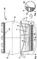
- FIG. 1 a schematic cross section through an elastomer insert 1 is shown.
- the elastomer insert 1 has an outer side 2 which is adapted to the transverse opening into which it is to be inserted.
- the inside 3 of the elastomer insert 1 has a conical screw area 4, for this purpose an internal thread is formed.
- a sealing element 12 in the form of a lip is also formed, which is formed immediately after the conical screw area 4 on the inside 3 of the elastomer insert 1 in the area of increasing conicity.
- the sealing element 12 projects inwards into the free space of the elastomer insert 1, which is delimited by the inside 3.
- the sealing element 12 is formed along the entire inner circumference on the inside 3 of the elastomer insert 1 in a uniform manner, in particular with the same cross section.
- connection piece 5 In the Fig. 2 a schematic lateral external view of a connection piece 5 is shown.
- connection piece 5 has an engagement end 6, with which it can be inserted into the elastomer insert 1 and then screwed in first.
- the connecting piece 5 further comprises a conical central part 7 on which an external thread 8 is formed. Adjacent to the conical middle part 7 of the connecting piece 5, a receiving section 9 is formed which is designed such that a secondary pipe (not shown here) can be connected to the connecting piece 5 in a fluid-tight manner.
- the drive end 11 adjoins the receiving section 9 of the connecting piece 5, on which extensions are formed which are suitable for screwing the connecting piece 5 into the elastomer insert 1 with the aid of a turning tool.
- a sealing surface 13 is formed, which is in the form of a conical envelope section surface.
- the sealing surface 13 extends around the entire connection piece 5 and has the same inclination with respect to the axis A of the connection piece 5 at all points.
- connection device 10 In the Fig. 3 a schematic, partially sectioned, external side view of a connection device 10 is shown.
- connection piece 5 is screwed completely into the elastomer insert 1.
- the internal thread formed on the inside 3 of the elastomer insert 1 interacts on the conical screw area 4 with the external thread 8 on the conical middle part 7 of the connecting piece.
- connection piece 5 As the connection piece 5 is completely screwed into the elastomer insert 1, which forms the connection device 10, the sealing element 12 in the form of a lip on the inside 3 of the elastomer insert 1 makes contact with the sealing surface 13 on the connection piece 5 and thus ensures the fluid-tight connection of the connection piece 5 with the elastomer insert 1.
- Fig. 4 is a detail X from the Fig. 3 shown.
- the detail X of the Fig. 3 is in the Fig. 4 shown enlarged. It is shown that the sealing element 12 in the form of a lip, which is formed on the inside 3 of the elastomer insert 1, is in flat press contact with the sealing surface 13 on the outer surface of the connecting piece 5.
- FIG. 5 a schematic sectional detailed view of a connector 5 inserted into an elastomer insert 1 is shown.
- FIG. 5 shows the state in which the connecting piece 5 is inserted into the elastomer insert 1 with the engagement end 6 of the connecting piece 5 first.
- the sealing element 12 protrudes from the elastomer insert 1 on its inside 3 in the form of a lip.
- the sealing element 12 in the form of a lip is formed along the entire inner circumference on the inside 3 of the elastomer insert 1 in a uniform manner, in particular with the same cross section.
- the sealing surface 13 of the connecting piece 5 extends around the entire connecting piece 5 and has the same inclination at all points with respect to the axis A of the connecting piece 5, which is not shown here.
- FIG. 6 a schematic sectional detailed view of a connecting piece 5 screwed into an elastomer insert 1 is shown.
- the external thread 8 on the conical middle part 7 of the connecting piece 5 interacts with the internal thread of the conical screw area 4 on the elastomer insert 1.
- the sealing element 12 in the form of a lip makes contact with the sealing surface 13 of the connecting piece 5 over the entire circumference by means of a flat pressing.
- the sealing element 12 in the form of a lip, which protrudes from the inside 3, is folded over through the sealing surface 13 towards the inside 3 of the elastomer insert 1.
- a fluid-tight connection of the connecting piece 5 and the elastomer insert 1 to the connecting device 10 is established by the folded lip.
- the folded lip increases the pressure on the outside 2 of the elastomer insert 1 against the reveal of the transverse opening in a main pipeline, in a shaft or in a wall in the section of the outside 2 opposite the folded lip, which improves the tightness at this point causes.
- the sealing element 12 is provided approximately opposite a sealing projection 2a on the outside 2 of the elastomer insert 1, which when the connecting piece 5 is screwed into the elastomer insert 1 against the reveal of the transverse opening in a main pipeline, in a shaft or is pressed in a wall and at this point ensures improved fluid tightness and a greater permissible borehole tolerance for the transverse opening.
Description
- Die Erfindung betrifft eine Anschlussvorrichtung, die einen Elastomereinsatz und einen Anschlussstutzen umfasst.
- Des Weiteren betrifft die Erfindung ein Fluidleit-, -aufnahme- und -speichersystem mit einer solchen Anschlussvorrichtung.
- Eine gattungsgemäße Anschlussvorrichtung, die einen Elastomereinsatz und einen Anschlussstutzen umfasst, ist aus der
DE 20 2006 005 685 U1 bekannt. Eine solche Anschlussvorrichtung ist geeignet, eine Nebenrohrleitung fluiddicht an eine Queröffnung in einer Hauptleitung, einem Schacht oder einer Wand anzuschließen. Derartige Anschlussvorrichtungen müssen sicher installierbar und dauerhaft sein und eine hohe Fluiddichtheit aufweisen. - Zur Herstellung der Anschlussvorrichtung wird zunächst der Elastomereinsatz in die Queröffnung einer Hauptleitung, eines Schachtes oder einer Wand eingesetzt, und anschließend der Anschlussstutzen in den Elastomereinsatz eingeschraubt, um die Außenfläche des Elastomereinsatzes möglichst großflächig an die Laibung der Queröffnung anzupressen.
- Zum Einschrauben ist an der Innenseite des hohlstopfenförmig ausgebildeten Elastomereinsatzes ein Innengewinde ausgebildet, entsprechend an der Außenseite des Anschlussstutzens ein Außengewinde. Zum Einschrauben des Anschlussstutzens in den Elastomereinsatz zur Bildung der Anschlussvorrichtung wird im Allgemeinen ein Drehwerkzeug benutzt.
- Es hat sich herausgestellt, dass die Fluiddichtheit einer solchen Anschlussvorrichtung bei nicht sachgerechter Installation, insbesondere bei nichtaxialem Einschrauben des Anschlussstutzens in den Elastomereinsatz, gegebenenfalls zu Undichtigkeiten führt und daher verbesserungsbedürftig ist.
- So kann es in besonderen Fällen vorkommen, dass Fluid sich einen Weg sucht zwischen dem Außengewinde an der Außenseite des Anschlussstutzens und dem Innengewinde an der Innenseite des Elastomereinsatzes und unerwünscht aus der Anschlussvorrichtung nach außen oder von außen in die Anschlussvorrichtung dringt.
- Hier setzt die Erfindung ein, der die Aufgabe zugrunde liegt, eine verbesserte Anschlussvorrichtung bereitzustellen, die gegenüber der bekannten Lösung des Standes der Technik eine verbesserte Fluiddichtheit aufweist.
- Eine weitere Aufgabe der Erfindung ist es, ein Fluidleit-, -aufnahme- und -speichersystem bereitzustellen, welches eine solche Anschlussvorrichtung umfasst.
- Die erste gestellte Aufgabe wird durch die Anschlussvorrichtung gemäß Anspruch 1 gelöst.
- Es ist im Rahmen der vorliegenden Erfindung vorgesehen, dass die Anschlussvorrichtung für eine Nebenrohrleitung in Kombination mit einer Queröffnung in einer Hauptrohrleitung, in einem Schacht oder in einer Wand einen hohlstopfenförmigen, relativ weichen Elastomereinsatz und einen relativ härteren Anschlussstutzen umfasst, wobei der Elastomereinsatz, dessen Außenseite an die Queröffnung angepasst ist, an seiner Innenseite einen konischen Schraubbereich aufweist, und der Anschlussstutzen ein Eingriffsende, einen konischen Mittelteil mit Außengewinde, einen Aufnahmeabschnitt und ein Antriebsende.
- Die erfindungsgemäße Anschlussvorrichtung zeichnet sich dadurch aus, dass der Elastomereinsatz an der Innenseite wenigstens ein Dichtelement aufweist, und dass der Anschlussstutzen am konischen Mittelteil eine Dichtfläche aufweist, wobei bei montierter Anschlussvorrichtung, bei der der Anschlussstutzen in den Elastomereinsatz eingeschraubt ist, das Dichtelement an der Innenseite des Elastomereinsatzes an der Dichtfläche am konischen Mittelteil des Anschlussstutzens anliegt.
- Durch das Vorsehen gemäß vorliegender Erfindung, dass bei montierter Anschlussvorrichtung, bei der der Anschlussstutzen in den Elastomereinsatz eingeschraubt ist, das Dichtelement an der Innenseite des Elastomereinsatzes an der Dichtfläche am konischen Mittelteil des Anschlussstutzens anliegt, ist eine verbesserte Anschlussvorrichtung geschaffen, die eine erhöhte Fluiddichtheit aufweist.
- So kann insbesondere Fluid, das zwischen den Anschlussstutzen und den Elastomereinsatz gelangt, aufgrund des an der Dichtfläche anliegenden Dichtelements nicht weiterwandern, und nicht unerwünscht aus der Anschlussvorrichtung austreten bzw. von außen in die Anschlussvorrichtung eintreten.
- Erfindungsgemäß ist das Dichtelement an der Innenseite des Elastomereinsatzes als Lippe ausgebildet.
- Ein als Lippe ausgebildetes Dichtelement an der Innenseite des Elastomereinsatzes ist besonders dafür ausgebildet, eine hohe Fluiddichtheit der erfindungsgemäßen Anschlussvorrichtung sicherzustellen.
- Bei der vorliegenden Erfindung kann sich als sehr vorteilhaft erweisen, wenn vorgesehen ist, dass das Dichtelement einstückig mit dem Elastomereinsatz ausgebildet ist, oder dass das Dichtelement in einem Aufnahmeabschnitt des Elastomereinsatzes aufgenommen ist. Wenn das Dichtelement einstückig mit dem Elastomereinsatz ausgebildet ist, kann ein derartiger Elastomereinsatz in einem einfachen Fertigungsverfahren hergestellt werden, indem in dem zur Formgebung des Elastomereinsatzes vorgesehenen Werkzeug eine entsprechende Kontur und ein entsprechender Freiraum zur Formung des Dichtelements ausgebildet ist.
- Bei einem Dichtelement, das in einem Aufnahmeabschnitt des Elastomereinsatzes aufgenommen ist, kann vorgesehen sein, dass das Dichtelement aus einem anderen Material besteht, als der Elastomereinsatz. Hierdurch ist es möglich, das Dichtelement aus einem Material mit beispielsweise einer anderen Härte herzustellen, als der Elastomereinsatz. Auch kann auf diese Weise eine individuelle Fertigung von Elastomereinsätzen mit Lippen oder Wülsten als Dichtelementen je nach Vorgabe des Kunden oder der technischen Notwendigkeit in einfacher Weise stattfinden.
- Als besonders vorteilhaft kann sich bei der vorliegenden Erfindung ergeben, wenn vorgesehen ist, dass zwei oder drei oder vier Dichtelemente an der Innenseite des Elastomereinsatzes ausgebildet sind.
- Durch die vorstehend beschriebene Maßnahme kann eine Ausbildung der Anschlussvorrichtung genau nach der Kundenspezifikation oder nach technischen Anforderungen erfolgen.
- Als besonders günstig kann sich bei der vorliegenden Erfindung ergeben, wenn vorgesehen ist, dass die Dichtfläche am konischen Mittelteil des Anschlussstutzens als Kegelmantelabschnittsfläche ausgebildet ist.
- Durch die Ausbildung der Dichtfläche am konische Mittelteil des Anschlussstutzens in Form einer Kegelmantelabschnittsfläche wird eine besonders hohe Fluiddichtheit erreicht, wenn sich an diese Dichtfläche ein Dichtelement anlegt.
- In weiterer Fortbildung der vorliegenden Erfindung kann sich als sehr günstig erweisen, wenn vorgesehen ist, dass die Dichtfläche am konischen Mittelteil des Anschlussstutzens um den konischen Mittelteil herumlaufend ausgebildet ist.
- Durch die Ausbildung der Dichtfläche am konischen Mittelteil des Anschlussstutzens derart, dass diese um den konischen Mittelteil herumlaufend ausgebildet ist, kann eine besonders fluiddicht installierbare Anschlussvorrichtung bereitgestellt werden.
- In besonders vorteilhafter Weise kann bei der vorliegenden Erfindung vorgesehen sein, dass der Elastomereinsatz aus einem Elastomermaterial besteht oder ein Elastomermaterial enthält, wobei das Elastomermaterial bevorzugt ein Gummi oder ein Thermoplastisches Elastomer oder ein Kautschuk oder ein Nitrilkautschuk oder ein Butylkautschuk oder ein EPDM (Ethylen-Propylen-Dien-Kautschuk) oder ein SBR (Styrol-Butadien-Kautschuk) ist und / oder der Anschlussstutzen aus einem Polymermaterial besteht oder ein Polymermaterial enthält, wobei das Polymermaterial bevorzugt ein Thermoplast, und besonders bevorzugt ein Polyolefin, wie beispielsweise ein Polypropylen oder ein Polyethylen oder ein Polybutylen, oder ein Copolymeres der Vorgenannten, oder ein vernetztes Polyolefin, insbesondere ein vernetztes Polyethylen, oder ein Polyvinylchlorid, oder ein Polyurethan ist.
- Derartige Elastomermaterialien bzw. Polymermaterialien sind langlebig, inert, stabil, weisen ein geringes Gewicht auf, sind einfach handhabbar, leicht installierbar und können kostengünstig bereitgestellt werden. Insbesondere ist es auf diese Weise sehr einfach, aus diesen Materialien den Elastomereinsatz bzw. den Anschlussstutzen zu bilden.
- Mit Vorteil kann ein solcher erfindungsgemäßer Elastomereinsatz bzw. ein solcher erfindungsgemäßer Anschlussstutzen mit Hilfe eines Polymerformgebungsverfahrens hergestellt sein.
- Insbesondere durch ein Spritzgussverfahren und / oder ein Blasverfahren und / oder ein Thermoformverfahren und / oder ein Pressverfahren kann ein derartiger Elastomereinsatz bzw, ein derartiger Anschlussstutzen leicht fertigbar sein.
- Alternativ kann vorgesehen sein, dass der Elastomereinsatz und / oder der Anschlussstutzen unter Verwendung eines generativen Fertigungsverfahrens, beispielsweise durch ein 3-D-Druckverfahren, hergestellt ist.
- Hierzu kann mit Vorteil ein datenverarbeitungsmaschinenlesbares dreidimensionales Modell für die Herstellung genutzt werden.
- Die Erfindung umfasst auch ein Verfahren zur Erzeugung eines datenverarbeitungsmaschinenlesbaren dreidimensionalen Modells zur Verwendung in einem Herstellungsverfahren für einen Elastomereinsatz und / oder einen Anschlussstutzen. Hierbei umfasst das Verfahren insbesondere auch die Eingabe von Daten, die einen Elastomereinsatz und / oder einen Anschlussstutzen darstellen, in eine Datenverarbeitungsmaschine und die Nutzung der Daten, um einen Elastomereinsatz und / oder einen Anschlussstutzen als dreidimensionales Modell darzustellen, wobei das dreidimensionale Modell geeignet ist zur Nutzung bei der Herstellung eines Elastomereinsatzes und / oder eines Anschlussstutzens. Ebenfalls umfasst ist bei dem Verfahren eine Technik, bei der die eingegebenen Daten eines oder mehrerer 3D-Scanner, die entweder auf Berührung oder berührungslos funktionieren, wobei bei letzteren Energie auf einen Elastomereinsatz und / oder einen Anschlussstutzen abgegeben wird und die reflektierte Energie empfangen wird, und wobei ein virtuelles dreidimensionales Modell eines Elastomereinsatzes und / oder eines Anschlussstutzens unter Verwendung einer computer-unterstützten Design-Software erzeugt wird.
- Das Fertigungsverfahren kann ein generatives Pulverbettverfahren, insbesondere selektives Laserschmelzen (SLM), selektives Lasersintern (SLS), selektives Hitzesintern (Selective Heat Sintering - SHS), selektives Elektronenstrahlschmelzen (Electron Beam Melting - EBM / Electron Beam Additive Manufacturing - EBAM) oder Verfestigen von Pulvermaterial mittels Binder (Binder Jetting) umfassen. Das Fertigungsverfahren kann ein generatives Freiraumverfahren, insbesondere Auftragsschweißen, Wax Deposition Modeling (WDM), Contour Crafting, Metall-Pulver-Auftragsverfahren (MPA), Kunststoff-Pulver-Auftragsverfahren, Kaltgasspritzen, Elektronenstrahlschmelzen (Electron Beam Welding - EBW) oder Schmelzeschichtungsverfahren wie Fused Deposition Modeling (FDM) oder Fused Filament Fabrication (FFF) umfassen. Das Fertigungsverfahren kann ein generatives Flüssigmaterialverfahren, insbesondere Stereolithografie (SLA), Digital Light Processing (DLP), Multi Jet Modeling (MJM), Polyjet Modeling oder Liquid Composite Moulding (LCM) umfassen. Ferner kann das Fertigungsverfahren andere generative Schichtaufbauverfahren, insbesondere Laminated Object Modelling (LOM), 3D-Siebdruck oder die Lichtgesteuerte Elektrophoretische Abscheidung umfassen.
- Die Aufgabe der vorliegenden Erfindung, ein Fluidleit-, -aufnahme- und -speichersystem anzugeben, erfährt ihre Lösung in Anspruch 7.
- Das erfindungsgemäße Fluidleit-, -aufnahme- und -speichersystem umfasst eine Nebenrohrleitung, eine Hauptrohrleitung und / oder einen Schacht und / oder eine Wand, und eine Anschlussvorrichtung für eine Nebenrohrleitung in Kombination mit einer Queröffnung in einer Hauptrohrleitung, in einem Schacht oder in einer Wand gemäß vorstehender Beschreibung.
- Anwendung findet die vorliegende Erfindung insbesondere im Bereich der Kanal- und Abwassertechnik.
- Neben der geschilderten Anwendung gibt es weitere Anwendungsfelder in der Regenwasserbewirtschaftung, bei Hausanschlüssen, in Kläranlagen, in der Schwimmbadtechnik, in der Industrie, in der Landwirtschaft und in weiteren Bereichen.
- Weitere wichtige Merkmale und Vorteile der Erfindung ergeben sich aus den Unteransprüchen, aus den Figuren und aus der zugehörigen Figurenbeschreibung.
- Bevorzugte Ausführungsbeispiele der Erfindung sind in den Fig. dargestellt und werden in der nachfolgenden Beschreibung näher ausgeführt.
- Die Erfindung wird anhand der beigefügten Figuren näher erläutert.
- Hierzu zeigt:
- Fig. 1:
- einen schematischen Querschnitt durch einen Elastomereinsatz;
- Fig. 2:
- eine schematische seitliche Außenansicht eines Anschlussstutzens,
- Fig.3:
- eine schematische teilweise geschnittene seitliche Außenansicht einer Anschlussvorrichtung;
- Fig. 4:
- ein Detail aus der
Fig. 3 ; - Fig. 5:
- eine schematische geschnittene Detailansicht eines in einen Elastomereinsatz eingesteckten Anschlussstutzens;
- Fig. 6:
- eine schematische geschnittene Detailansicht eines in einen Elastomereinsatz eingeschraubten Anschlussstutzens.
- In der
Fig. 1 ist ein schematischer Querschnitt durch einen Elastomereinsatz 1 gezeigt. Der Elastomereinsatz 1 weist eine Außenseite 2 auf, die an die Queröffnung angepasst ist, in die er eingesetzt werden soll. - Die Innenseite 3 des Elastomereinsatzes 1 weist einen konischen Schraubbereich 4 auf, hierzu ist ein Innengewinde ausgebildet. An der Innenseite 3 des Elastomereinsatzes ist weiterhin ein Dichtelement 12 in Form einer Lippe ausgebildet, welche unmittelbar nach dem konischen Schraubbereich 4 an der Innenseite 3 des Elastomereinsatzes 1 im Bereich der zunehmenden Konizität ausgebildet ist.
- Das Dichtelement 12 steht nach innen in den Freiraum des Elastomereinsatzes 1, der durch die Innenseite 3 begrenzt wird, vor.
- Das Dichtelement 12 ist entlang des gesamten Innenumfangs an der Innenseite 3 des Elastomereinsatzes 1 in gleichmäßiger Weise, insbesondere mit gleichem Querschnitt, ausgebildet.
- In der
Fig. 2 ist eine schematische seitliche Außenansicht eines Anschlussstutzens 5 gezeigt. - Der Anschlussstutzen 5 weist ein Eingriffsende 6 auf, mit dem voran er in den Elastomereinsatz 1 einsteckbar und anschließend einschraubbar ist. Der Anschlussstutzen 5 umfasst weiterhin einen konischen Mittelteil 7, an dem ein Außengewinde 8 ausgebildet ist. Anschließend an den konischen Mittelteil 7 des Anschlussstutzens 5 ist ein Aufnahmeabschnitt 9 ausgebildet, der derartig ausgebildet ist, dass ein hier nicht gezeigtes Nebenrohr fluiddicht mit dem Anschlussstutzen 5 verbindbar ist.
- An den Aufnahmeabschnitt 9 des Anschlussstutzens 5 grenzt das Antriebsende 11 an, an dem Fortsätze ausgebildet sind, die dazu geeignet sind, den Anschlussstutzen 5 mithilfe eines Drehwerkzeugs in den Elastomereinsatz 1 einzuschrauben.
- Zwischen dem Eingriffsende 6 des Anschlussstutzens 5 und dem konischen Mittelteil 7 ist eine Dichtfläche 13 ausgebildet, die in Form einer Kegelmantelabschnittsfläche ausgebildet ist.
- Die Dichtfläche 13 zieht sich um den gesamten Anschlussstutzen 5 herum und weist an allen Stellen die gleiche Neigung gegenüber der Achse A des Anschlussstutzens 5 auf.
- In der
Fig. 3 ist eine schematische teilweise geschnittene seitliche Außenansicht einer Anschlussvorrichtung 10 gezeigt. - Die Bezugszeichen in
Fig. 3 entsprechen denen aus den vorangehenden Figuren. - Bei der dargestellten Anschlussvorrichtung 10 ist der Anschlussstutzen 5 in den Elastomereinsatz 1 vollständig eingeschraubt. Hierzu interagiert das an der Innenseite 3 des Elastomereinsatzes 1 ausgebildete Innengewinde am konischen Schraubbereich 4 mit dem Au-ßengewinde 8 am konischen Mittelteil 7 des Anschlussstutzens.
- Durch das vollständige Einschrauben des Anschlussstutzens 5 in den Elastomereinsatz 1, durch den die Anschlussvorrichtung 10 gebildet ist, kontaktiert das Dichtelement 12 in Form einer Lippe an der Innenseite 3 des Elastomereinsatzes 1 die Dichtfläche 13 am Anschlussstutzen 5 und sorgt so für die fluiddichte Verbindung des Anschlussstutzens 5 mit dem Elastomereinsatz 1.
- In der
Fig. 4 ist ein Detail X aus derFig. 3 gezeigt. - Die Bezugszeichen in
Fig. 4 entsprechen denen aus den vorangehenden Figuren. - Das Detail X der
Fig. 3 ist in derFig. 4 vergrößert dargestellt. Gezeigt ist, dass das Dichtelement 12 in Form einer Lippe, welche an der Innenseite 3 des Elastomereinsatzes 1 ausgebildet ist, in einem flächigen Presskontakt mit der Dichtfläche 13 an der Außenoberfläche des Anschlussstutzens 5 steht. - Dadurch ist eine fluiddichte Verbindung zwischen dem Anschlussstutzen 5 und dem Elastomereinsatz 1 geschaffen.
- In der
Fig. 5 ist eine schematische geschnittene Detailansicht eines in einen Elastomereinsatz 1 eingesteckten Anschlussstutzens 5 dargestellt. - Die Bezugszeichen in
Fig. 5 entsprechen denen aus den vorangehenden Figuren. - In der
Fig. 5 ist der Zustand gezeigt, bei dem der Anschlussstutzen 5 mit dem Eingriffsende 6 des Anschlussstutzens 5 voran in den Elastomereinsatz 1 eingesteckt ist. Vom Elastomereinsatz 1 steht an dessen Innenseite 3 das Dichtelement 12 in Form einer Lippe hervor. - Das Dichtelement 12 in Form einer Lippe ist entlang des gesamten Innenumfangs an der Innenseite 3 des Elastomereinsatzes 1 in gleichmäßiger Weise, insbesondere mit gleichem Querschnitt, ausgebildet.
- Die Dichtfläche 13 des Anschlussstutzens 5 zieht sich um den gesamten Anschlussstutzen 5 herum und weist an allen Stellen die gleiche Neigung gegenüber der hier nicht gezeigten Achse A des Anschlussstutzens 5 auf.
- In der
Fig. 6 ist eine schematische geschnittene Detailansicht eines in einen Elastomereinsatz 1 eingeschraubten Anschlussstutzens 5 gezeigt. - Die Bezugszeichen in
Fig. 6 entsprechen denen der vorangehenden Figuren. - In den in
Fig. 6 gezeigten Zustand ist der Anschlussstutzen 5 mit dem Elastomereinsatz 1 verschraubt und bildet so die Anschlussvorrichtung 10. - Für die Verschraubung interagiert das Außengewinde 8 am konischen Mittelteil 7 des Anschlussstutzens 5 mit dem Innengewinde des konischen Schraubbereichs 4 am Elastomereinsatz 1.
- Im vollständig verschraubten Zustand des Anschlussstutzens 5 und des Elastomereinsatzes 1 zur Anschlussvorrichtung 10 kontaktiert das Dichtelement 12 in Form einer Lippe durch eine flächige Pressung die Dichtfläche 13 des Anschlussstutzens 5 über den gesamten Umfang.
- Hierzu ist das Dichtelement 12 in Form einer Lippe, die von der Innenseite 3 hervorsteht, durch die Dichtfläche 13 zur Innenseite 3 des Elastomereinsatzes 1 hin umgelegt. Durch die umgelegte Lippe wird eine fluiddichte Verbindung des Anschlussstutzens 5 und des Elastomereinsatzes 1 zur Anschlussvorrichtung 10 hergestellt.
- Durch die umgelegte Lippe erfolgt eine erhöhte Anpressung der Außenseite 2 des Elastomereinsatzes 1 an die Laibung der Queröffnung in einer Hauptrohrleitung, in einem Schacht oder in einer Wand in dem Abschnitt der Außenseite 2, die der umgelegten Lippe gegenüberliegt, was eine verbesserte Dichtheit an dieser Stelle bewirkt.
- In einer besonderen Ausgestaltung der Erfindung ist vorgesehen, dass dem Dichtelement 12 etwa gegenüberliegend ein Dichtvorsprung 2a an der Außenseite 2 des Elastomereinsatzes 1 vorgesehen ist, der beim Einschrauben des Anschlussstutzens 5 in den Elastomereinsatz 1 gegen die Laibung der Queröffnung in einer Hauptrohrleitung, in einem Schacht oder in einer Wand gepresst wird und an dieser Stelle für eine verbesserte Fluiddichtheit und eine größere zulässige Bohrlochtoleranz für die Queröffnung sorgt.
-
- 1
- Elastomereinsatz
- 2
- Außenseite
- 2a
- Dichtvorsprung
- 3
- Innenseite
- 4
- konischer Schraubbereich
- 5
- Anschlussstutzen
- 6
- Eingriffsende
- 7
- konischer Mittelteil
- 8
- Außengewinde
- 9
- Aufnahmeabschnitt
- 10
- Anschlussvorrichtung
- 11
- Antriebsende
- 12
- Dichtelement
- 13
- Dichtfläche
- 20
- Fluidleit-, -aufnahme- und -speichersystem
- A
- Achse
- X
- Detail
Claims (7)
- Anschlussvorrichtung (10) für eine Nebenrohrleitung in Kombination mit einer Queröffnung in einer Hauptrohrleitung, in einem Schacht oder in einer Wand, umfassend:einen hohlstopfenförmigen, relativ weichen Elastomereinsatz (1), dessen Außenseite (2) an die Queröffnung angepasst ist, und dessen Innenseite (3) einen konischen Schraubbereich (4) aufweist, undeinen relativ härteren Anschlussstutzen (5), der ein Eingriffsende (6), einen konischen Mittelteil (7) mit Außengewinde (8), einen Aufnahmeabschnitt (9) und ein Antriebsende (11) aufweist,wobei der Elastomereinsatz (1) an der Innenseite (3) wenigstens ein Dichtelement (12) aufweist,und der Anschlussstutzen (5) am konischen Mittelteil (7) eine Dichtfläche (13) aufweist,dadurch gekennzeichnet,dass das Dichtelement (12) in Form einer Lippe ausgebildet ist, die von der Innenseite (3) des Elastomereinsatzes (1) hervorsteht,wobei bei montierter Anschlussvorrichtung (10), bei der der Anschlussstutzen (5) in den Elastomereinsatz (1) eingeschraubt ist, das Dichtelement (12) an der Innenseite (3) des Elastomereinsatzes (1) an der Dichtfläche (13) am konischen Mittelteil (7) des Anschlussstutzens (5) anliegt.
- Anschlussvorrichtung (10) nach Anspruch 1, dadurch gekennzeichnet, dass das Dichtelement (12) einstückig mit dem Elastomereinsatz (1) ausgebildet ist, oder dass das Dichtelement (12) in einem Aufnahmeabschnitt des Elastomereinsatzes (1) aufgenommen ist.
- Anschlussvorrichtung (10) nach einem der Ansprüche 1 oder 2, dadurch gekennzeichnet, dass zwei oder drei oder vier Dichtelemente (12) an der Innenseite (3) des Elastomereinsatzes (1) ausgebildet sind.
- Anschlussvorrichtung (10) nach einem der vorangehenden Ansprüche, dadurch gekennzeichnet, dass die Dichtfläche (13) am konischen Mittelteil (7) des Anschlussstutzens (5) als Kegelmantelabschnittsfläche ausgebildet ist.
- Anschlussvorrichtung (10) nach einem der vorangehenden Ansprüche, dadurch gekennzeichnet, dass die Dichtfläche (13) am konischen Mittelteil (7) des Anschlussstutzens (5) um den konischen Mittelteil (7) herumlaufend ausgebildet ist.
- Anschlussvorrichtung (10) nach einem der vorangehenden Ansprüche, dadurch gekennzeichnet, dass der Elastomereinsatz aus einem Elastomermaterial besteht oder ein Elastomermaterial enthält, wobei das Elastomermaterial bevorzugt ein Gummi oder ein Thermoplastisches Elastomer oder ein Kautschuk oder ein Nitrilkautschuk oder ein Butylkautschuk oder ein EPDM (Ethylen-Propylen-Dien-Kautschuk) oder ein SBR (Styrol-Butadien-Kautschuk) ist und / oder der Anschlussstutzen aus einem Polymermaterial besteht oder ein Polymermaterial enthält, wobei das Polymermaterial bevorzugt ein Thermoplast, und besonders bevorzugt ein Polyolefin, wie beispielsweise ein Polypropylen oder ein Polyethylen oder ein Polybutylen, oder ein Copolymeres der Vorgenannten, oder ein vernetztes Polyolefin, insbesondere ein vernetztes Polyethylen, oder ein Polyvinylchlorid, oder ein Polyurethan ist.
- Fluidleit-, -aufnahme- und -speichersystem (20) umfassend eine Nebenrohrleitung, eine Hauptrohrleitung und / oder einen Schacht und / oder eine Wand, und eine Anschlussvor-richtung (10) für eine Nebenrohrleitung in Kombination mit einer Queröffnung in einer Haupt-rohrleitung, in einem Schacht oder in einer Wand , nach einem der Ansprüche 1 bis 6.
Applications Claiming Priority (1)
| Application Number | Priority Date | Filing Date | Title |
|---|---|---|---|
| DE202017104710.5U DE202017104710U1 (de) | 2017-08-07 | 2017-08-07 | Anschlussvorrichtung |
Publications (2)
| Publication Number | Publication Date |
|---|---|
| EP3441660A1 EP3441660A1 (de) | 2019-02-13 |
| EP3441660B1 true EP3441660B1 (de) | 2021-06-23 |
Family
ID=63103789
Family Applications (1)
| Application Number | Title | Priority Date | Filing Date |
|---|---|---|---|
| EP18186242.6A Active EP3441660B1 (de) | 2017-08-07 | 2018-07-30 | Anschlussvorrichtung |
Country Status (2)
| Country | Link |
|---|---|
| EP (1) | EP3441660B1 (de) |
| DE (1) | DE202017104710U1 (de) |
Family Cites Families (5)
| Publication number | Priority date | Publication date | Assignee | Title |
|---|---|---|---|---|
| DE19617437A1 (de) * | 1996-05-02 | 1997-11-06 | Hermann Muecher Gmbh | Elastomere Ringraumdichtung |
| DE29918122U1 (de) * | 1999-10-14 | 2000-01-20 | Mol Gummiverarbeitung | Manschettendichtung zum seitlichen Anschluß eines Anschlußstutzens an ein Kanalisationsrohr |
| US6557825B2 (en) * | 2001-03-30 | 2003-05-06 | Cherne Industries Incorporated | Air admittance valve connector assembly |
| DE202006005685U1 (de) | 2006-04-05 | 2007-08-16 | Rehau Ag + Co | Anschlussvorrichtung für eine Nebenrohrleitung |
| DE102008021470A1 (de) * | 2008-04-29 | 2009-11-19 | Pt-Poly-Tec Gmbh Vertrieb Und Herstellung Von Dichtungssystemen | Elastomereinsatz für einen Nebenrohranschluss |
-
2017
- 2017-08-07 DE DE202017104710.5U patent/DE202017104710U1/de not_active Expired - Lifetime
-
2018
- 2018-07-30 EP EP18186242.6A patent/EP3441660B1/de active Active
Also Published As
| Publication number | Publication date |
|---|---|
| EP3441660A1 (de) | 2019-02-13 |
| DE202017104710U1 (de) | 2018-11-08 |
Similar Documents
| Publication | Publication Date | Title |
|---|---|---|
| EP3489565B1 (de) | Anschlussvorrichtung | |
| EP3441660B1 (de) | Anschlussvorrichtung | |
| DE202007011453U1 (de) | Anschluss- oder Verbindungsteil für eine Wellrohr- oder Wellschlauchleitung | |
| DE102011011215B4 (de) | Verfahren zum Verbinden und Verbindung eines ersten Werkstückes mit einem zweiten Werkstück | |
| DE202017101503U1 (de) | Verschraubbarer Abzweig für ein Unebenheiten aufweisendes Kanalrohr | |
| EP3441661B1 (de) | Anschlussvorrichtung | |
| EP3296606B1 (de) | Anschlussvorrichtung | |
| DE202017104669U1 (de) | Anschlusselement | |
| EP3458758B1 (de) | Brandschutzelement sowie verfahren zur herstellung eines brandschutzelements | |
| DE102014009408A1 (de) | Verfahren zur Herstellung eines Faserverbundkunststoff-Bauteils | |
| EP3832186B1 (de) | Anschlusssystem mit einer trennkennzeichnung | |
| DE202017105796U1 (de) | Anschlussvorrichtung | |
| EP3832188B1 (de) | Anschlusssystem mit einem ansatzelement | |
| DE102015225067A1 (de) | Innendruckbelastetes Bauteil (Rail) mit Kunststoffauskleidung | |
| DE202019105911U1 (de) | Anschlusssystem | |
| EP3441662B1 (de) | Anschlussstutzen | |
| DE2028710A1 (de) | Verfahren zur Montage einer Schlauch-Endarmatur | |
| EP3372885A1 (de) | Dichtungselement | |
| EP3985296B1 (de) | Anschlusssystem | |
| DE202018100554U1 (de) | Adapterbauteil | |
| DE2710852A1 (de) | Rohrmuffenanordnung | |
| EP4108409B1 (de) | Spritzgiessverfahren und spreizkern | |
| DE102021130624A1 (de) | Abdichtungssystem | |
| DE202017107706U1 (de) | Dichtungselement | |
| DE2216745B1 (de) | Verfahren zum verbinden von kunststoffteilen mittels ultraschall und schweissteil zur durchfuehrung des verfahrens |
Legal Events
| Date | Code | Title | Description |
|---|---|---|---|
| PUAI | Public reference made under article 153(3) epc to a published international application that has entered the european phase |
Free format text: ORIGINAL CODE: 0009012 |
|
| STAA | Information on the status of an ep patent application or granted ep patent |
Free format text: STATUS: THE APPLICATION HAS BEEN PUBLISHED |
|
| AK | Designated contracting states |
Kind code of ref document: A1 Designated state(s): AL AT BE BG CH CY CZ DE DK EE ES FI FR GB GR HR HU IE IS IT LI LT LU LV MC MK MT NL NO PL PT RO RS SE SI SK SM TR |
|
| AX | Request for extension of the european patent |
Extension state: BA ME |
|
| STAA | Information on the status of an ep patent application or granted ep patent |
Free format text: STATUS: REQUEST FOR EXAMINATION WAS MADE |
|
| 17P | Request for examination filed |
Effective date: 20190812 |
|
| RBV | Designated contracting states (corrected) |
Designated state(s): AL AT BE BG CH CY CZ DE DK EE ES FI FR GB GR HR HU IE IS IT LI LT LU LV MC MK MT NL NO PL PT RO RS SE SI SK SM TR |
|
| RAP1 | Party data changed (applicant data changed or rights of an application transferred) |
Owner name: REHAU AG + CO |
|
| GRAP | Despatch of communication of intention to grant a patent |
Free format text: ORIGINAL CODE: EPIDOSNIGR1 |
|
| STAA | Information on the status of an ep patent application or granted ep patent |
Free format text: STATUS: GRANT OF PATENT IS INTENDED |
|
| INTG | Intention to grant announced |
Effective date: 20210315 |
|
| GRAS | Grant fee paid |
Free format text: ORIGINAL CODE: EPIDOSNIGR3 |
|
| GRAA | (expected) grant |
Free format text: ORIGINAL CODE: 0009210 |
|
| STAA | Information on the status of an ep patent application or granted ep patent |
Free format text: STATUS: THE PATENT HAS BEEN GRANTED |
|
| AK | Designated contracting states |
Kind code of ref document: B1 Designated state(s): AL AT BE BG CH CY CZ DE DK EE ES FI FR GB GR HR HU IE IS IT LI LT LU LV MC MK MT NL NO PL PT RO RS SE SI SK SM TR |
|
| REG | Reference to a national code |
Ref country code: GB Ref legal event code: FG4D Free format text: NOT ENGLISH |
|
| REG | Reference to a national code |
Ref country code: CH Ref legal event code: EP |
|
| REG | Reference to a national code |
Ref country code: DE Ref legal event code: R096 Ref document number: 502018005793 Country of ref document: DE Ref country code: AT Ref legal event code: REF Ref document number: 1404595 Country of ref document: AT Kind code of ref document: T Effective date: 20210715 |
|
| REG | Reference to a national code |
Ref country code: IE Ref legal event code: FG4D Free format text: LANGUAGE OF EP DOCUMENT: GERMAN |
|
| REG | Reference to a national code |
Ref country code: LT Ref legal event code: MG9D |
|
| PG25 | Lapsed in a contracting state [announced via postgrant information from national office to epo] |
Ref country code: LT Free format text: LAPSE BECAUSE OF FAILURE TO SUBMIT A TRANSLATION OF THE DESCRIPTION OR TO PAY THE FEE WITHIN THE PRESCRIBED TIME-LIMIT Effective date: 20210623 Ref country code: HR Free format text: LAPSE BECAUSE OF FAILURE TO SUBMIT A TRANSLATION OF THE DESCRIPTION OR TO PAY THE FEE WITHIN THE PRESCRIBED TIME-LIMIT Effective date: 20210623 Ref country code: FI Free format text: LAPSE BECAUSE OF FAILURE TO SUBMIT A TRANSLATION OF THE DESCRIPTION OR TO PAY THE FEE WITHIN THE PRESCRIBED TIME-LIMIT Effective date: 20210623 Ref country code: BG Free format text: LAPSE BECAUSE OF FAILURE TO SUBMIT A TRANSLATION OF THE DESCRIPTION OR TO PAY THE FEE WITHIN THE PRESCRIBED TIME-LIMIT Effective date: 20210923 |
|
| PG25 | Lapsed in a contracting state [announced via postgrant information from national office to epo] |
Ref country code: GR Free format text: LAPSE BECAUSE OF FAILURE TO SUBMIT A TRANSLATION OF THE DESCRIPTION OR TO PAY THE FEE WITHIN THE PRESCRIBED TIME-LIMIT Effective date: 20210924 Ref country code: LV Free format text: LAPSE BECAUSE OF FAILURE TO SUBMIT A TRANSLATION OF THE DESCRIPTION OR TO PAY THE FEE WITHIN THE PRESCRIBED TIME-LIMIT Effective date: 20210623 Ref country code: NO Free format text: LAPSE BECAUSE OF FAILURE TO SUBMIT A TRANSLATION OF THE DESCRIPTION OR TO PAY THE FEE WITHIN THE PRESCRIBED TIME-LIMIT Effective date: 20210923 Ref country code: SE Free format text: LAPSE BECAUSE OF FAILURE TO SUBMIT A TRANSLATION OF THE DESCRIPTION OR TO PAY THE FEE WITHIN THE PRESCRIBED TIME-LIMIT Effective date: 20210623 Ref country code: RS Free format text: LAPSE BECAUSE OF FAILURE TO SUBMIT A TRANSLATION OF THE DESCRIPTION OR TO PAY THE FEE WITHIN THE PRESCRIBED TIME-LIMIT Effective date: 20210623 |
|
| REG | Reference to a national code |
Ref country code: NL Ref legal event code: MP Effective date: 20210623 |
|
| PG25 | Lapsed in a contracting state [announced via postgrant information from national office to epo] |
Ref country code: RO Free format text: LAPSE BECAUSE OF FAILURE TO SUBMIT A TRANSLATION OF THE DESCRIPTION OR TO PAY THE FEE WITHIN THE PRESCRIBED TIME-LIMIT Effective date: 20210623 Ref country code: PT Free format text: LAPSE BECAUSE OF FAILURE TO SUBMIT A TRANSLATION OF THE DESCRIPTION OR TO PAY THE FEE WITHIN THE PRESCRIBED TIME-LIMIT Effective date: 20211025 Ref country code: NL Free format text: LAPSE BECAUSE OF FAILURE TO SUBMIT A TRANSLATION OF THE DESCRIPTION OR TO PAY THE FEE WITHIN THE PRESCRIBED TIME-LIMIT Effective date: 20210623 Ref country code: CZ Free format text: LAPSE BECAUSE OF FAILURE TO SUBMIT A TRANSLATION OF THE DESCRIPTION OR TO PAY THE FEE WITHIN THE PRESCRIBED TIME-LIMIT Effective date: 20210623 Ref country code: SK Free format text: LAPSE BECAUSE OF FAILURE TO SUBMIT A TRANSLATION OF THE DESCRIPTION OR TO PAY THE FEE WITHIN THE PRESCRIBED TIME-LIMIT Effective date: 20210623 Ref country code: SM Free format text: LAPSE BECAUSE OF FAILURE TO SUBMIT A TRANSLATION OF THE DESCRIPTION OR TO PAY THE FEE WITHIN THE PRESCRIBED TIME-LIMIT Effective date: 20210623 Ref country code: ES Free format text: LAPSE BECAUSE OF FAILURE TO SUBMIT A TRANSLATION OF THE DESCRIPTION OR TO PAY THE FEE WITHIN THE PRESCRIBED TIME-LIMIT Effective date: 20210623 Ref country code: EE Free format text: LAPSE BECAUSE OF FAILURE TO SUBMIT A TRANSLATION OF THE DESCRIPTION OR TO PAY THE FEE WITHIN THE PRESCRIBED TIME-LIMIT Effective date: 20210623 |
|
| PG25 | Lapsed in a contracting state [announced via postgrant information from national office to epo] |
Ref country code: PL Free format text: LAPSE BECAUSE OF FAILURE TO SUBMIT A TRANSLATION OF THE DESCRIPTION OR TO PAY THE FEE WITHIN THE PRESCRIBED TIME-LIMIT Effective date: 20210623 |
|
| REG | Reference to a national code |
Ref country code: DE Ref legal event code: R081 Ref document number: 502018005793 Country of ref document: DE Owner name: REHAU INDUSTRIES SE & CO. KG, DE Free format text: FORMER OWNER: REHAU AG + CO, 95111 REHAU, DE |
|
| REG | Reference to a national code |
Ref country code: DE Ref legal event code: R097 Ref document number: 502018005793 Country of ref document: DE |
|
| PG25 | Lapsed in a contracting state [announced via postgrant information from national office to epo] |
Ref country code: MC Free format text: LAPSE BECAUSE OF FAILURE TO SUBMIT A TRANSLATION OF THE DESCRIPTION OR TO PAY THE FEE WITHIN THE PRESCRIBED TIME-LIMIT Effective date: 20210623 |
|
| PG25 | Lapsed in a contracting state [announced via postgrant information from national office to epo] |
Ref country code: DK Free format text: LAPSE BECAUSE OF FAILURE TO SUBMIT A TRANSLATION OF THE DESCRIPTION OR TO PAY THE FEE WITHIN THE PRESCRIBED TIME-LIMIT Effective date: 20210623 |
|
| PLBE | No opposition filed within time limit |
Free format text: ORIGINAL CODE: 0009261 |
|
| STAA | Information on the status of an ep patent application or granted ep patent |
Free format text: STATUS: NO OPPOSITION FILED WITHIN TIME LIMIT |
|
| 26N | No opposition filed |
Effective date: 20220324 |
|
| PG25 | Lapsed in a contracting state [announced via postgrant information from national office to epo] |
Ref country code: LU Free format text: LAPSE BECAUSE OF NON-PAYMENT OF DUE FEES Effective date: 20210730 Ref country code: AL Free format text: LAPSE BECAUSE OF FAILURE TO SUBMIT A TRANSLATION OF THE DESCRIPTION OR TO PAY THE FEE WITHIN THE PRESCRIBED TIME-LIMIT Effective date: 20210623 |
|
| REG | Reference to a national code |
Ref country code: BE Ref legal event code: PD Owner name: REHAU INDUSTRIES SE & CO. KG; DE Free format text: DETAILS ASSIGNMENT: CHANGE OF OWNER(S), OTHER; FORMER OWNER NAME: REHAU AG + CO Effective date: 20220414 |
|
| PG25 | Lapsed in a contracting state [announced via postgrant information from national office to epo] |
Ref country code: IT Free format text: LAPSE BECAUSE OF FAILURE TO SUBMIT A TRANSLATION OF THE DESCRIPTION OR TO PAY THE FEE WITHIN THE PRESCRIBED TIME-LIMIT Effective date: 20210623 Ref country code: IE Free format text: LAPSE BECAUSE OF NON-PAYMENT OF DUE FEES Effective date: 20210730 Ref country code: FR Free format text: LAPSE BECAUSE OF NON-PAYMENT OF DUE FEES Effective date: 20210823 |
|
| GBPC | Gb: european patent ceased through non-payment of renewal fee |
Effective date: 20220730 |
|
| PG25 | Lapsed in a contracting state [announced via postgrant information from national office to epo] |
Ref country code: GB Free format text: LAPSE BECAUSE OF NON-PAYMENT OF DUE FEES Effective date: 20220730 |
|
| PG25 | Lapsed in a contracting state [announced via postgrant information from national office to epo] |
Ref country code: CY Free format text: LAPSE BECAUSE OF FAILURE TO SUBMIT A TRANSLATION OF THE DESCRIPTION OR TO PAY THE FEE WITHIN THE PRESCRIBED TIME-LIMIT Effective date: 20210623 |
|
| PG25 | Lapsed in a contracting state [announced via postgrant information from national office to epo] |
Ref country code: HU Free format text: LAPSE BECAUSE OF FAILURE TO SUBMIT A TRANSLATION OF THE DESCRIPTION OR TO PAY THE FEE WITHIN THE PRESCRIBED TIME-LIMIT; INVALID AB INITIO Effective date: 20180730 |
|
| PGFP | Annual fee paid to national office [announced via postgrant information from national office to epo] |
Ref country code: CH Payment date: 20230801 Year of fee payment: 6 |
|
| PGFP | Annual fee paid to national office [announced via postgrant information from national office to epo] |
Ref country code: DE Payment date: 20230731 Year of fee payment: 6 Ref country code: BE Payment date: 20230630 Year of fee payment: 6 |
|
| PG25 | Lapsed in a contracting state [announced via postgrant information from national office to epo] |
Ref country code: MK Free format text: LAPSE BECAUSE OF FAILURE TO SUBMIT A TRANSLATION OF THE DESCRIPTION OR TO PAY THE FEE WITHIN THE PRESCRIBED TIME-LIMIT Effective date: 20210623 |