EP3441659A1 - Fluidleitungselement für eine fluidleitung - Google Patents
Fluidleitungselement für eine fluidleitung Download PDFInfo
- Publication number
- EP3441659A1 EP3441659A1 EP18185147.8A EP18185147A EP3441659A1 EP 3441659 A1 EP3441659 A1 EP 3441659A1 EP 18185147 A EP18185147 A EP 18185147A EP 3441659 A1 EP3441659 A1 EP 3441659A1
- Authority
- EP
- European Patent Office
- Prior art keywords
- attachment
- channel
- fluid
- fluid line
- line element
- Prior art date
- Legal status (The legal status is an assumption and is not a legal conclusion. Google has not performed a legal analysis and makes no representation as to the accuracy of the status listed.)
- Granted
Links
Images


Classifications
-
- F—MECHANICAL ENGINEERING; LIGHTING; HEATING; WEAPONS; BLASTING
- F16—ENGINEERING ELEMENTS AND UNITS; GENERAL MEASURES FOR PRODUCING AND MAINTAINING EFFECTIVE FUNCTIONING OF MACHINES OR INSTALLATIONS; THERMAL INSULATION IN GENERAL
- F16L—PIPES; JOINTS OR FITTINGS FOR PIPES; SUPPORTS FOR PIPES, CABLES OR PROTECTIVE TUBING; MEANS FOR THERMAL INSULATION IN GENERAL
- F16L41/00—Branching pipes; Joining pipes to walls
- F16L41/008—Branching pipes; Joining pipes to walls for connecting a measuring instrument
-
- G—PHYSICS
- G01—MEASURING; TESTING
- G01L—MEASURING FORCE, STRESS, TORQUE, WORK, MECHANICAL POWER, MECHANICAL EFFICIENCY, OR FLUID PRESSURE
- G01L19/00—Details of, or accessories for, apparatus for measuring steady or quasi-steady pressure of a fluent medium insofar as such details or accessories are not special to particular types of pressure gauges
- G01L19/0007—Fluidic connecting means
Definitions
- the invention relates to a fluid line element for a fluid line according to the preamble of patent claim 1.
- the fluid line element has at least one connection device for an attachment, at least one fluid channel and at least one attachment channel, wherein the attachment channel branches off from the fluid channel.
- Fluid conduit elements are known in the art in a variety of configurations. In fluid-conducting systems in vehicles, aqueous fluids or water are increasingly being conducted in fluid-conducting systems. The operating parameters of the fluid are monitored or checked by means of sensors.
- the sensors used for this purpose eg. As pressure sensors, often include sensitive components, such as membranes that are prone to damage, especially for damage caused by the formation of ice.
- the present invention is based on the object of specifying a fluid line element for a fluid line, in which damage to attachments due to ice formation is reliably prevented.
- the above object is achieved in a generic fluid line element with the features of the characterizing part of patent claim 1, namely, characterized in that the attachment channel has along its extension at least one deflection.
- the fluid conduit element is advantageous for use in a motor vehicle provided.
- the attachment channel establishes the fluidic connection between the fluid channel and the attachment, in particular with measuring or sensor technology of the attachment.
- the attachment channel provides a fluidic connection between the fluid channel and a sensor unit of a pressure sensor, in particular a silicon membrane.
- the attachment channel is particularly designed so that its branch on the fluid channel and its course within the attachment, in particular within a sensor, are not coaxial.
- the attachment channel has at least one first section which is not oriented parallel to a second section of the attachment channel within the attachment, for example a sensor unit.
- the attachment channel preferably has at least two different extension directions.
- the attachment channel at least in a section on a curved and / or curved course.
- the deflection is preferably arranged in the course of the attachment channel between the fluid channel and the connection device.
- deflection is meant a change in the geometry of the attachment channel which would cause a directional change of the fluid in a flowing fluid.
- the deflection is realized, for example, by a change in the direction of the attachment with a constant cross section, for example a bow, and / or by a change in cross section of the attachment channel.
- the deflection caused by the change in direction of the attachment channel refers to a central axis of the attachment channel.
- the deflection is formed as a cross-sectional change, from which the supply and discharge of the attachment channel not branch off coaxially, in particular branch off in different directions.
- the deflection ensures that in the case of ice formation, in particular by frost, an ice column forming within the attachment channel not or only slightly within the Anbauteilkanals, in particular by the force of a later forming in the fluid channel ice column, in the direction of the attachment, in particular the Sensor unit of a sensor, is displaceable. This will damage the attachment prevents mechanical action of an ice column forming in the attachment.
- the geometry of the attachment channel is thus chosen so that an ice column forming therein, in particular by the deflection, does not shift.
- the deflection includes a change in direction of the attachment channel of at least 75 °, in particular at least 90 °, preferably from 180 °.
- the change of direction refers to an origin direction, starting from the branch of the attachment channel from the fluid line.
- the angle refers to any imaginary plane that contains the original direction.
- the subsequent course does not necessarily have to be oriented to the imaginary level.
- the attachment channel starting from the fluid line, in particular from its branch starting from the fluid line, directly has a curved course, in particular with a change in direction of 180 °, preferably with a constant radius of curvature.
- the attachment channel is at least partially closed by a removable cover on the fluid line element. The curved shape ensures that the ice column can not be moved.
- distance of the attachment channel can be realized, which ensures an ice formation within the Anbauteilkanals time before the fluid channel.
- the cross section of the attachment channel is smaller than the cross section of the fluid channel.
- the cross section of the attachment channel is only 20%, preferably 10%, particularly preferably 5% of the cross section of the fluid channel.
- the abovementioned percentage data relate in each case to the area of the cross section, in particular to the smallest cross section of the attachment channel.
- the cross section of the attachment channel is formed constant or varying along its extension. In the case of a varying cross section, however, the cross section is preferably always smaller than the cross section of the fluid channel.
- the attachment channel has at least one section whose cross section is smaller than the cross section of the fluid channel.
- the cross section of the attachment channel is at least in the region of the deflection less than the cross section of the fluid channel.
- the attachment channel runs at least partially in the fluid line element and at least partially in the attachment part.
- the deflection can for example be realized in that a part of the attachment channel forming geometry in Fluid line element and a part of the geometry is formed in the attachment, whereby a simple demolding of the components during manufacture is ensured.
- the attachment channel thus extends from the fluid channel to an actual sensor unit of an attachment.
- the production of the fluid line element can be simplified in that the deflection is arranged in the fluid line element and / or in the attachment.
- the arrangement of the deflection only in the fluid line element has the advantage that standardized attachments can be used, but at the same time damage due to ice formation is reliably prevented.
- a part of the deflection of the attachment channel in the fluid line element and a further part of the deflection in the attachment is arranged.
- the attachment must be specially designed.
- an adapter is arranged between connection device and attachment, which includes a part of the attachment channel, so that standardized attachment parts, in particular standardized sensors, can be used.
- the cross section of the attachment channel in the fluid line element is less than the cross section of the attachment channel in the attachment.
- the section of the attachment channel in the attachment in particular in the sensor, has a standardized cross-section. The cross-section of the attachment channel in the fluid conduit member is then made smaller in order to ensure the formation of an ice column in the region with the smallest cross-section temporally first.
- the attachment channel in particular a central axis of the attachment channel, runs in an imaginary plane E1, wherein the plane E1 includes a central axis of the fluid channel.
- the attachment channel preferably runs at least partially parallel to the fluid channel.
- the deflection, in particular with an angle of preferably 90 °, is also arranged in the plane E1.
- the attachment channel runs in a plane E2, to which the central axis of the fluid channel is a normal.
- the attachment channel thus extends at least partially in a direction orthogonal to the central axis of the fluid channel.
- a temporally successive solidification of an ice column in the attachment channel or in the fluid channel is further promoted by the attachment channel being at least partially surrounding the fluid channel, particularly in a region having a midpoint angle about the central axis of the fluid channel of about 135 °.
- the midpoint angle preferably extends in the previously described plane E2.
- the attachment channel extends in particular at least in a section parallel to a tangent to the cross section of the fluid channel.
- the production of a fluid line element can advantageously be simplified in that the attachment channel has a semicircular cross section at least in sections.
- a semicircular cross-section can be demolded in a simple manner.
- the attachment channel at least partially composed of a first half-shell on or in the fluid line element and a further half-shell on or in the attachment.
- the deflection is arranged partially or completely in the attachment, in particular in the sensor, has been found to be advantageous according to an embodiment, if it is provided that the attachment is secured with a rotation against rotation relative to the connection device.
- the anti-rotation prevents the attachment channel from shifting unintentionally.
- connection device is designed as a receptacle for a sensor, in particular for a pressure sensor.
- the Connection device and the attachment preferably each have a retaining collar, which are held together by means of a mounting ring such that the attachment, in particular a sensor, is held captive in the connection device.
- the connection device has sealing surfaces for a seal surrounding the attachment, in particular an O-ring seal.
- the fluid line element is designed as a connector piece, in particular angle piece or T piece, for connecting fluid lines.
- a T-piece on the one hand two fluid-carrying lines for connecting and on the other hand a connection device for an attachment, in particular a pressure sensor available. The same applies to a designed as an angle piece fluid line element.
- the geometries of the fluid channel and of the attachment channel are advantageously selected and matched to one another such that, under the influence of temperatures which lead to solidification of the guided fluid, the formation of an ice column within the attachment channel, in particular at least in a section of the attachment channel, completed before the formation of an ice column within the fluid channel.
- Fig. 1 . Fig. 2a and Fig. 2b show an embodiment of a fluid line element 1 for a fluid line with at least one connection device 2 for an attachment 3.
- the attachment 3 is formed in this embodiment as a pressure sensor.
- the fluid line element 1 has at least one fluid channel 4 and at least one attachment channel 5.
- the fluid channel extends between a first end 1a and a second end 1b of the fluid line element 1.
- the attachment channel 5 branches off from the fluid channel 4 and extends between the fluid channel 4 and a sensor element 6 of the attachment 3 - see Fig. 2a ,
- Fig. 2a and Fig. 2b has the attachment channel along its extension between the fluid channel 4 and the sensor element 6, in particular the membrane of the attachment 3 to a deflection 7, which is formed in this embodiment as a curved course 8 with a change in direction of 180 °.
- the arcuate course 8 has a constant radius of curvature.
- the attachment channel 4 is closed at least in one area by a removable cover 9.
- the cross section of the attachment channel 5 is smaller than the cross section of the fluid channel 4.
- the cross section of a first section 5a of the attachment channel 5 within the fluid line element 1 is smaller than the cross section of a second section 5b of the attachment channel 5 within the attachment 3.
- the arcuate course 8 prevents an ice column forming within the attachment channel 5 from being displaced within the attachment channel 5; on the other hand, by guiding the attachment channel, in particular the section 5a around the fluid channel 4, a temporally successive freezing of the attachment channel first 5 and then the fluid channel 4 guaranteed.
- the Fig. 2 and 2a It can also be seen that the connection device 2 is arranged off-center.
- Fig. 2a extends the attachment channel 5 in an imaginary plane E2, to which the central axis M of the fluid channel 4 is a normal.
- the attachment channel 5 extends at least partially surrounding the fluid channel 4, in this case with a center angle ⁇ of about 135 ° about the central axis M.
- the first portion 5a extends at least in sections parallel to a tangent to the cross section of the fluid channel 4.
- the formed as a pressure sensor Attachment 3 has in this embodiment, a first retaining collar 10 which on a second retaining collar 11 of the connecting device 2 is applied.
- the attachment 3 projects at least partially into the connection device 2 and is sealed with a circumferential O-ring seal 12.
- the attachment 3 and the connecting device 2 are connected to a retaining ring 13 with each other.
- the retaining ring is flexible and removable.
- Fig. 3 . 4 and FIG. 5 show a further embodiment of a fluid conduit element 1 in various sectional views or enlargements.
- the connection device 2 is an attachment 3 introduced and secured with a retaining ring 13.
- the retaining ring 13 engages over the retaining collar 10 and the retaining collar 11.
- two deflections 7 are provided.
- the deflections 7 of the attachment channel 5 is located within the fluid line element 1. Starting from the fluid line 4, the attachment channel 5 undergoes a change of direction of about 90 ° and goes into a semi-circular profile - see also Fig. 5 -. Subsequently, a further change of direction of 90 ° is completed, so that the attachment channel 5 extends with its portion 5b further within the attachment part 3. Within the attachment 3, no deflection is provided in this embodiment.
- the cross section in the section 5a within the fluid conduit element 1 is less than the cross section in section 5b within the attachment part 3.
- Fig. 3 and Fig. 5 It can be seen that the attachment channel 5 is in an imaginary plane E1 together with the central axis M of the fluid channel 4, so that the connection device 2 is arranged centrally above the fluid channel 4.
- Fig. 4 shows an enlargement of the section B according to Fig. 3 in that it can be seen that the deflection 7 is arranged exclusively in the fluid line element 1, so that the attachment 3 can be designed in a standardized manner.
- the cross section of the attachment channel 5 is significantly smaller than the cross section of the fluid channel 4. Consequently, in the case of a frost effect, an ice column, which is not displaceable due to the deflections 7, first forms in the attachment channel 5, in particular not by a force effect of an ice column forming in the fluid channel 4.
- Fig. 6 . Fig. 7 . Fig. 8 and Fig. 9 show a further embodiment of a fluid conduit element 1 in various sectional views.
- Fig. 6 shows that the deflections 7 of the attachment channel 5 are arranged within the attachment part 3.
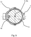
- an in Fig. 9 shown anti-rotation 14 is provided which prevents rotation of the attachment 3 relative to the connection device 2, in particular by a positive connection.
- the portion 5a of the attachment channel 5 is formed as a straight branch from the fluid channel.
- the attachment is specially designed and has a half-shell-shaped recess, which forms the attachment channel 5 with the deflections 7.
- Fig. 6 and Fig. 8 show that also in this embodiment, the attachment channel 5 is arranged in an imaginary plane E1, which also includes the central axis M of the fluid channel 4.
- Fig. 6 is in the connection device 2 designed as a pressure sensor attachment 3 and positively connected to a retaining ring 13.
- the anti-rotation 14 is at least partially formed on the retaining collar 11.
- the invention is not limited to the illustrated and described embodiments, but also includes all the same in the context of the invention embodiments. It is expressly emphasized that the exemplary embodiments are not limited to all the features in combination, but rather each individual partial feature may also have an inventive meaning independently of all other partial features. Furthermore, the invention has hitherto not been limited to the feature combination defined in claim 1, but may also be defined by any other combination of certain features of all the individual features disclosed overall. This means that in principle virtually every single feature of claim 1 can be omitted or replaced by at least one individual feature disclosed elsewhere in the application.
Landscapes
- Engineering & Computer Science (AREA)
- General Engineering & Computer Science (AREA)
- Physics & Mathematics (AREA)
- General Physics & Mathematics (AREA)
- Mechanical Engineering (AREA)
- Measuring Fluid Pressure (AREA)
Abstract
Description
- Die Erfindung betrifft ein Fluidleitungselement für eine Fluidleitung gemäß dem Oberbegriff des Patentanspruchs 1. Das Fluidleitungselement weist mindestens eine Anschlussvorrichtung für ein Anbauteil, mindestens einen Fluidkanal und mindestens einen Anbauteilkanal auf, wobei der Anbauteilkanal von dem Fluidkanal abzweigt.
- Fluidleitungselemente sind im Stand der Technik in einer Vielzahl von Ausgestaltungen bekannt. In fluidleitenden Systemen in Fahrzeugen werden immer häufiger wässrige Fluide oder Wasser in fluidleitenden Systemen geführt. Die Betriebsparameter des Fluids werden dabei mittels Sensoren überwacht bzw. überprüft. Die dazu verwendeten Sensoren, z. B. Drucksensoren, beinhalten häufig empfindliche Bauteile, beispielsweise Membrane, die anfällig für Beschädigungen sind, insbesondere für Beschädigungen durch Einwirkung von Eisbildung.
- Dabei ist es aus dem Stand der Technik bekannt, Fluidleitungen und Anbauteile, z. B. Sensoren, frostsicher auszulegen oder zu beheizen, wodurch allerdings die Kosten deutlich steigen.
- Der vorliegenden Erfindung liegt ausgehend von dem vorgenannten Stand der Technik die Aufgabe zu Grunde, ein Fluidleitungselement für eine Fluidleitung anzugeben, bei dem eine Beschädigung von Anbauteilen durch Eisbildung zuverlässig verhindert wird.
- Die vorgenannte Aufgabe ist bei einem gattungsgemäßen Fluidleitungselement mit den Merkmalen des kennzeichnenden Teils des Patentanspruchs 1 gelöst, nämlich dadurch dass der Anbauteilkanal entlang seiner Erstreckung mindestens eine Umlenkung aufweist. Das Fluidleitungselement ist vorteilhaft zur Verwendung in einem Kraftfahrzeug vorgesehen. Der Anbauteilkanal stellt die fluidtechnische Verbindung zwischen dem Fluidkanal und dem Anbauteil, insbesondere mit Mess- bzw. Sensortechnik des Anbauteils her. Vorzugsweise stellt der Anbauteilkanal eine fluidtechnische Verbindung zwischen dem Fluidkanal und einer Sensoreinheit eines Drucksensors, insbesondere einer Siliziummembran, her. Der Anbauteilkanal ist insbesondere so ausgebildet, dass seine Abzweigung am Fluidkanal und sein Verlauf innerhalb des Anbauteils, insbesondere innerhalb eines Sensors, nicht koaxial sind. Der Anbauteilkanal weist mindestens einen ersten Abschnitt auf, der nicht parallel zu einem zweiten Abschnitt des Anbauteilkanals innerhalb des Anbauteils, beispielsweise einer Sensoreinheit, orientiert ist. Der Anbauteilkanal weist vorzugsweise mindestens zwei unterschiedliche Erstreckungsrichtungen auf. Vorzugsweise weist der Anbauteilkanal mindestens in einem Abschnitt einen bogen- und/oder kurvenförmigen Verlauf auf.
- Die Umlenkung ist vorzugsweise in Verlauf des Anbauteilkanals zwischen dem Fluidkanal und der Anschlussvorrichtung angeordnet. Unter "Umlenkung" ist eine Änderung der Geometrie des Anbauteilkanals zu verstehen, die bei einem strömenden Fluid eine Richtungsänderung des Fluids hervorrufen würde. Die Umlenkung ist beispielsweise durch eine Änderung der Richtung des Anbauteils bei gleichbleibendem Querschnitt, beispielsweise einem Bogen, und/oder durch eine Querschnittsänderung des Anbauteilkanals realisiert. Vorzugsweise bezieht sich die durch die Umlenkung hervorgerufene Richtungsänderung des Anbauteilkanals auf eine Mittelachse des Anbauteilkanals. Beispielsweise ist die Umlenkung als Querschnittsveränderung ausgebildet, von der die Zu- und Ableitung des Anbauteilkanals nicht koaxial abzweigen, insbesondere in unterschiedlichen Richtungen abzweigen.
- Durch die Umlenkung wird gewährleistet, dass im Falle von Eisbildung, insbesondere durch Frost, eine sich innerhalb des Anbauteilkanals ausbildende Eissäule nicht oder nur unwesentlich innerhalb des Anbauteilkanals, insbesondere durch die Kraftwirkung einer sich später im Fluidkanal ausbildenden Eissäule, in Richtung des Anbauteils, insbesondere der Sensoreinheit eines Sensors, verschiebbar ist. Dadurch wird eine Beschädigung des Anbauteils durch mechanische Einwirkung einer sich im Anbauteil ausbildenden Eissäule verhindert. Die Geometrie des Anbauteilkanals ist folglich so gewählt, dass sich eine darin bildende Eissäule, insbesondere durch die Umlenkung, nicht verschiebt.
- Gemäß einer Ausgestaltung des Fluidleitungselements hat sich als vorteilhaft herausgestellt, wenn vorgesehen ist, dass die Umlenkung eine Richtungsänderung des Anbauteilkanals von mindestens 75°, insbesondere mindestens 90°, bevorzugt von 180° beinhaltet. Die Richtungsänderung bezieht sich auf eine Ursprungsrichtung, ausgehend von dem Abzweig des Anbauteilkanals von der Fluidleitung. Die Winkelangabe bezieht sich beispielsweise auf jede gedachte Ebene, die die ursprüngliche Richtung beinhaltet. Dabei muss der nachfolgende Verlauf nicht zwingend an der gedachten Ebene orientiert sein. Mit einer Umlenkung mit einem der vorgenannten Winkel kann vorteilhaft eine Verschiebung einer sich im Anbauteilkanal ausbildenden Eissäule verhindert werden.
- Gemäß einer weiteren Ausgestaltung ist bevorzugt vorgesehen, dass der Anbauteilkanal ausgehend von der Fluidleitung, insbesondere von seinem Abzweig ausgehend von der Fluidleitung, unmittelbar einen bogenförmigen Verlauf, insbesondere mit einer Richtungsänderung von 180°, bevorzugt mit einem konstanten Krümmungsradius, aufweist. Vorteilhaft ist zudem vorgesehen, dass der Anbauteilkanal zumindest teilweise von einem abnehmbaren Deckel am Fluidleitungselement verschlossen wird. Durch den bogenförmigen Verlauf wird sichergestellt, dass sich die Eissäule nicht verschieben lässt. Zudem kann mit dem bogenförmigen Verlauf eine längere, den Fluidkanal umgebende, Wegstrecke des Anbauteilkanals realisiert werden, die eine Eisbildung innerhalb des Anbauteilkanals zeitlich vor dem Fluidkanal gewährleistet.
- Die Herstellung eines derartigen bogenförmigen Verlaufes, insbesondere einer Richtungsänderung von 180°, wird vereinfacht, wenn der Anbauteilkanal zumindest abschnittsweise von einem abnehmbaren Deckel am Fluidleitungselement verschlossen ist. Dadurch ist eine Entformbarkeit des Fluidleitungselements bei der Herstellung gewährleistet, wobei der Deckel den Anbauteilkanal verschließt. Vorzugsweise ist vorgesehen, dass der Deckel federnd ausgebildet ist und/oder federnd am Fluidleitungselement gelagert ist, so dass bei sich ausbildender Eissäule eine Ausweichbewegung des Deckels ermöglicht ist, ohne dass dieser durch eine von der Eissäule ausgehende Kraftwirkung beschädigt oder entfernt wird.
- Insbesondere um im Fall von Frost ein zeitlich aufeinanderfolgendes Ausbilden von Eissäulen in dem Anbauteilkanal und anschließend in dem Fluidkanal zuverlässig zu gewährleisten, ist gemäß einer weiteren Ausgestaltung vorgesehen, dass der Querschnitt des Anbauteilkanals geringer als der Querschnitt des Fluidkanals ist. Insbesondere beträgt der Querschnitt des Anbauteilkanals lediglich 20%, bevorzugt 10%, besonders bevorzugt 5% des Querschnitts des Fluidkanals. Die vorgenannten prozentualen Angaben beziehen sich jeweils auf die Fläche des Querschnitts, insbesondere auf den kleinsten Querschnitt des Anbauteilkanals. Es ist vorgesehen, dass der Querschnitt des Anbauteilkanals entlang seiner Erstreckung konstant oder variierend ausgebildet ist. Im Falle eines variierenden Querschnitts ist der Querschnitt bevorzugt jedoch stets kleiner als der Querschnitt des Fluidkanals. Vorteilhaft weist der Anbauteilkanal mindestens einen Abschnitt auf, dessen Querschnitt geringer als der Querschnitt des Fluidkanals ist. Beispielsweise ist der Querschnitt des Anbauteilkanals zumindest im Bereich der Umlenkung geringer als der Querschnitt des Fluidkanals.
- Durch eine derartige Ausgestaltung kann sichergestellt werden, dass aufgrund des geringeren Volumens der Anbauteilkanal zeitlich vor dem Fluidkanal zufriert und sich eine innerhalb des Anbauteilkanals unverschiebliche Eissäule ausbildet. Wenn folglich anschließend der Fluidkanal zufriert, wird eine Verschiebung der Eissäule, insbesondere ausgehend von einer durch eine Eissäule innerhalb des Fluidkanals ausgehenden Krafteinwirkung, innerhalb des Anbauteilkanals verhindert und damit eine Beschädigung des Anbauteils, insbesondere eines Sensors, ausgeschlossen.
- Insbesondere um die Vielfalt der herstellbaren Umlenkungsgeometrien zu vergrößern, ist gemäß einer Weiterbildung des Fluidleitungselements vorgesehen, dass der Anbauteilkanal zumindest teilweise im Fluidleitungselement und zumindest teilweise im Anbauteil verläuft. Die Umlenkung kann beispielsweise dadurch realisiert sein, dass ein Teil der den Anbauteilkanal bildenden Geometrie im Fluidleitungselement und ein Teil der Geometrie im Anbauteil ausgebildet ist, wodurch eine einfache Entformbarkeit der Bauteile bei der Herstellung gewährleistet wird. Der Anbauteilkanal erstreckt sich folglich vom Fluidkanal bis zu einer eigentlichen Sensoreinheit eines Anbauteils.
- Beispielsweise die Fertigung des Fluidleitungselements lässt sich dadurch vereinfachen, dass die Umlenkung im Fluidleitungselement und/oder im Anbauteil angeordnet ist. Die Anordnung der Umlenkung lediglich im Fluidleitungselement hat den Vorteil, dass standardisierte Anbauteile verwendet werden können, bei denen aber gleichzeitig eine Beschädigung durch Eisbildung zuverlässig verhindert wird. Es ist aber auch vorgesehen, dass ein Teil der Umlenkung des Anbauteilkanals im Fluidleitungselement und ein weiterer Teil der Umlenkung im Anbauteil angeordnet ist. Dazu muss allerdings das Anbauteil speziell ausgebildet sein. Vorteilhaft ist auch vorgesehen, dass zwischen Anschlussvorrichtung und Anbauteil ein Adapter angeordnet ist, der einen Teil des Anbauteilkanals beinhaltet, so dass standardisierte Anbauteile, insbesondere standardisierte Sensoren, verwendbar sind.
- Für eine zeitlich aufeinanderfolgende Erstarrung der Eissäulen hat sich zudem als vorteilhaft herausgestellt, wenn der Querschnitt des Anbauteilkanals im Fluidleitungselement geringer ist als der Querschnitt des Anbauteilkanals im Anbauteil. Insbesondere bei standardisierten Anbauteilen weist der Abschnitt des Anbauteilkanals im Anbauteil, insbesondere im Sensor, einen standardisierten Querschnitt auf. Der Querschnitt des Anbauteilkanals im Fluidleitungselement wird dann geringer ausgebildet, um ein Entstehen einer Eissäule in dem Bereich mit dem geringsten Querschnitt zeitlich zuerst zu gewährleisten.
- Gemäß einer weiteren Ausgestaltung des Fluidleitungselements ist vorteilhaft, wenn der Anbauteilkanal, insbesondere eine Mittelachse des Anbauteilkanals, in einer gedachten Ebene E1 verläuft, wobei die Ebene E1 eine Mittelachse des Fluidkanals beinhaltet. Der Anbauteilkanal verläuft dabei vorzugsweise zumindest teilweise parallel zum Fluidkanal. Die Umlenkung, insbesondere mit einem Winkel von vorzugsweise 90°, ist dabei ebenfalls in der Ebene E1 angeordnet. Alternativ dazu ist vorgesehen, dass der Anbauteilkanal in einer Ebene E2 verläuft, zu der die Mittelachse des Fluidkanals eine Normale ist. Der Anbauteilkanal erstreckt sich folglich zumindest teilweise in einer Richtung orthogonal zur Mittelachse des Fluidkanals.
- Ein zeitlich aufeinanderfolgendes Erstarren einer Eissäule in dem Anbauteilkanal bzw. in dem Fluidkanal wird dadurch weiter gefördert, dass der Anbauteilkanal den Fluidkanal zumindest teilweise umgebend angeordnet ist, insbesondere in einem Bereich mit einem Mittelpunktswinkel um die Mittelachse des Fluidkanals von etwa 135°. Der Mittelpunktswinkel erstreckt sich dabei vorzugsweise in der zuvor beschriebenen Ebene E2. Der Anbauteilkanal erstreckt sich insbesondere zumindest in einem Abschnitt parallel zu einer Tangente an den Querschnitt des Fluidkanals. Wenn sich der Anbauteilkanal zumindest teilweise um den Fluidkanal herum erstreckt, wird eine frühzeitige Erstarrung des Fluids innerhalb des Anbauteilkanals gefördert.
- Die Fertigung eines Fluidleitungselements lässt sich gemäß einer weiteren Ausgestaltung vorteilhaft dadurch vereinfachen, dass der Anbauteilkanal zumindest abschnittsweise einen halbkreisförmigen Querschnitt aufweist. Ein halbkreisförmiger Querschnitt lässt sich auf einfache Weise entformen. Beispielsweise ist auch vorgesehen, dass sich der Anbauteilkanal zumindest abschnittsweise aus einer ersten Halbschale am oder im Fluidleitungselement und einer weiteren Halbschale am oder im Anbauteil zusammensetzt.
- Insbesondere bei Ausführungsbeispielen, bei denen die Umlenkung teilweise oder vollständig im Anbauteil, insbesondere im Sensor, angeordnet ist, hat sich gemäß einer Ausgestaltung als vorteilhaft herausgestellt, wenn vorgesehen ist, dass das Anbauteil mit einer Verdrehsicherung gegen ein Verdrehen gegenüber der Anschlussvorrichtung gesichert ist. Die Verdrehsicherung verhindert, dass sich der Anbauteilkanal unbeabsichtigt verschiebt.
- Vorzugsweise ist vorgesehen, dass die Anschlussvorrichtung als Aufnahme für einen Sensor ausgebildet ist, insbesondere für einen Drucksensor. Die Anschlussvorrichtung und das Anbauteil weisen vorzugsweise jeweils einen Haltekragen auf, die mittels eines Montagerings derart zusammenhaltbar sind, dass das Anbauteil, insbesondere ein Sensor, verliersicher in der Anschlussvorrichtung gehalten ist. Vorzugsweise weist die Anschlussvorrichtung Dichtflächen für eine das Anbauteil umgebende Dichtung, insbesondere eine O-Ring-Dichtung, auf.
- Besonders vorteilhaft ist gemäß einer weiteren Ausgestaltung, wenn vorgesehen ist, dass das Fluidleitungselement als Verbinderstück, insbesondere Winkelstück oder T-Stück, zum Verbinden von Fluidleitungen ausgebildet ist. Hierbei stellt ein T-Stück einerseits zwei fluidführende Leitungen zum Verbinden und andererseits eine Anschlussvorrichtung für ein Anbauteil, insbesondere einen Drucksensor zur Verfügung. Gleiches gilt für ein als Winkelstück ausgebildetes Fluidleitungselement.
- Gemäß der Erfindung sind die Geometrien des Fluidkanals und des Anbauteilkanals vorteilhaft so gewählt und aufeinander abgestimmt, dass bei einer Einwirkung von Temperaturen, die zu einer Erstarrung des geführten Fluides führen, die Ausbildung einer Eissäule innerhalb des Anbauteilkanals, insbesondere zumindest in einem Abschnitt des Anbauteilkanals, zeitlich vor der Ausbildung einer Eissäule innerhalb des Fluidkanals abgeschlossen ist.
- Weitere vorteilhafte Ausgestaltungen der Erfindung ergeben sich aus der folgenden Figurenbeschreibung und den Unteransprüchen. Im Folgenden wird die Erfindung anhand von Ausführungsbeispielen näher erläutert. Es zeigen:
- Fig. 1
- ein Ausführungsbeispiel eines Fluidleitungselements in Seitenansicht,
- Fig. 2a
- das Ausführungsbeispiel gemäß
Fig. 1 , geschnitten entlang der Linie A-A inFig. 1 , - Fig. 2b
- einen Schnitt durch das Ausführungsbeispiel gemäß
Fig. 1 ohne Anbauteil, - Fig. 3
- einen Schnitt durch ein Ausführungsbeispiel eines Fluidleitungselements,
- Fig. 4
- eine Vergrößerung im Bereich B der
Fig. 3 , - Fig. 5
- einen Schnitt durch das Ausführungsbeispiel gemäß
Fig. 3 , - Fig. 6
- ein Ausführungsbeispiel eines Fluidleitungselements in Schnittansicht,
- Fig. 7
- eine Vergrößerung im Bereich B der
Fig. 6 , - Fig. 8
- einen Schnitt durch das Ausführungsbeispiel gemäß
Fig. 6 und - Fig. 9
- einen Schnitt durch das Ausführungsbeispiel gemäß
Fig. 6 entlang der Linie C-C inFig. 6 . - In den verschiedenen Figuren der Zeichnung sind gleiche Teile stets mit denselben Bezugszeichen versehen.
- Zu der anschließenden Beschreibung wird ausdrücklich beansprucht, dass die Erfindung nicht auf alle oder mehrere Merkmale von beschriebenen Merkmalskombinationen beschränkt ist, vielmehr kann jedes einzelne Teilmerkmal des Ausführungsbeispiels auch losgelöst von allen anderen im Zusammenhang damit beschriebenen Teilmerkmalen für sich und auch in Kombination mit anderen Merkmalen sowie auch unabhängig von den Merkmalskombinationen und Rückbeziehungen der Ansprüche eine erfinderische Bedeutung in Verbindung mit dem Gegenstand des Anspruchs 1 haben.
-
Fig. 1 ,Fig. 2a und Fig. 2b zeigen ein Ausführungsbeispiel eines Fluidleitungselementes 1 für eine Fluidleitung mit mindestens einer Anschlussvorrichtung 2 für ein Anbauteil 3. Das Anbauteil 3 ist bei diesem Ausführungsbeispiel als Drucksensor ausgebildet. Das Fluidleitungselement 1 weist mindestens einen Fluidkanal 4 und mindestens einen Anbauteilkanal 5 auf. Der Fluidkanal erstreckt sich zwischen einem ersten Ende 1a und einem zweiten Ende 1b des Fluidleitungselements 1. Der Anbauteilkanal 5 zweigt von dem Fluidkanal 4 ab und erstreckt sich zwischen dem Fluidkanal 4 und einem Sensorelement 6 des Anbauteils 3 - sieheFig. 2a . - Gemäß
Fig. 2a und Fig. 2b weist der Anbauteilkanal entlang seiner Erstreckung zwischen dem Fluidkanal 4 und dem Sensorelement 6, insbesondere der Membran, des Anbauteils 3 eine Umlenkung 7 auf, die bei diesem Ausführungsbeispiel als bogenförmiger Verlauf 8 mit einer Richtungsänderung von 180° ausgebildet ist. Der bogenförmige Verlauf 8 weist einen konstanten Krümmungsradius auf. Bei diesem Ausführungsbeispiel ist der Anbauteilkanal 4 zumindest im einem Bereich von einem abnehmbaren Deckel 9 verschlossen. Der Querschnitt des Anbauteilkanals 5 ist geringer als der Querschnitt des Fluidkanals 4. Insbesondere ist der Querschnitt eines ersten Abschnitts 5a des Anbauteilkanals 5 innerhalb des Fluidleitungselements 1 geringer als der Querschnitt eines zweiten Abschnitts 5b des Anbauteilkanals 5 innerhalb des Anbauteils 3. - Durch den bogenförmigen Verlauf 8 wird einerseits verhindert, dass sich eine innerhalb des Anbauteilkanals 5 ausbildende Eissäule innerhalb des Anbauteilkanals 5 verschieben lässt, andererseits wird durch die Führung des Anbauteilkanals, insbesondere des Abschnitts 5a um den Fluidkanal 4 herum, ein zeitlich aufeinanderfolgendes Einfrieren zuerst des Anbauteilkanals 5 und anschließend des Fluidkanals 4 gewährleistet. Den
Fig. 2 und 2a ist ferner zu entnehmen, dass die Anschlussvorrichtung 2 außermittig angeordnet ist. - Gemäß
Fig. 2a verläuft der Anbauteilkanal 5 in einer gedachten Ebene E2, zu der die Mittelachse M des Fluidkanals 4 eine Normale ist. Der Anbauteilkanal 5 erstreckt sich zumindest teilweise umgebend um den Fluidkanal 4, vorliegend mit einem Mittelpunktswinkel α von etwa 135° um die Mittelachse M. Ferner verläuft der erste Abschnitt 5a zumindest abschnittsweise parallel zu einer Tangente an den Querschnitt des Fluidkanals 4. Das als Drucksensor ausgebildete Anbauteil 3 weist bei diesem Ausführungsbeispiel einen ersten Haltekragen 10 auf, der an einem zweiten Haltekragen 11 der Anschlussvorrichtung 2 anliegt. Das Anbauteil 3 ragt zumindest teilweise in die Anschlussvorrichtung 2 hinein und ist mit einer umlaufenden O-Ring-Dichtung 12 abgedichtet. Das Anbauteil 3 und die Anschlussvorrichtung 2 sind mit einem Haltering 13 miteinander verbunden. Der Haltering ist flexibel und entfernbar ausgebildet. -
Fig. 3 ,Fig. 4 und Fig. 5 zeigen ein weiteres Ausführungsbeispiel eines Fluidleitungselementes 1 in verschiedenen Schnittansichten bzw. Vergrößerungen. GemäßFig. 3 undFig. 4 ist die Anschlussvorrichtung 2 ein Anbauteil 3 eingebracht und mit einem Haltering 13 gesichert. Der Haltering 13 übergreift des Haltekragen 10 und den Haltekragen 11. Bei diesem Ausführungsbeispiel sind zwei Umlenkungen 7 vorgesehen. Die Umlenkungen 7 des Anbauteilkanals 5 befindet sich innerhalb des Fluidleitungselementes 1. Ausgehend von der Fluidleitung 4 vollzieht der Anbauteilkanal 5 einen Richtungswechsel von etwa 90° und geht in ein halbkreisförmiges Profil über - siehe auchFig. 5 -. Anschließend wird ein weiterer Richtungswechsel von 90° vollzogen, so dass sich der Anbauteilkanal 5 mit seinem Abschnitt 5b weiter innerhalb des Anbauteils 3 erstreckt. Innerhalb des Anbauteils 3 ist bei diesem Ausführungsbeispiel keine Umlenkung vorgesehen. - Der Querschnitt im Abschnitt 5a innerhalb des Fluidleitungselementes 1 ist geringer als der Querschnitt in Abschnitt 5b innerhalb des Anbauteils 3.
Fig. 3 undFig. 5 ist zu entnehmen, dass sich der Anbauteilkanal 5 in einer gedachten Ebene E1 zusammen mit der Mittelachse M des Fluidkanals 4 befindet, so dass die Anschlussvorrichtung 2 zentral oberhalb des Fluidkanals 4 angeordnet ist.Fig. 4 zeigt eine Vergrößerung des Ausschnitts B gemäßFig. 3 , der zu entnehmen ist, dass die Umlenkung 7 im ausschließlich im Fluidleitungselement 1 angeordnet ist, so dass das Anbauteil 3 standardisiert ausgebildet sein kann. Ferner istFig. 4 zu entnehmen, dass der Querschnitt des Anbauteilkanals 5 deutlich geringer als der Querschnitt des Fluidkanals 4 ist. Im Falle einer Frosteinwirkung bildet sich folglich zunächst im Anbauteilkanal 5 eine Eissäule, die aufgrund der Umlenkungen 7 nicht verschiebbar ist, insbesondere nicht durch eine Kraftwirkung einer sich im Fluidkanal 4 ausbildenden Eissäule. -
Fig. 6 ,Fig. 7 ,Fig. 8 undFig. 9 zeigen ein weiteres Ausführungsbeispiel eines Fluidleitungselementes 1 in verschiedenen Schnittansichten.Fig. 6 zeigt, dass die Umlenkungen 7 des Anbauteilkanals 5 innerhalb des Anbauteils 3 angeordnet sind. Um zu verhindern, dass eine Verdrehung des Anbauteilkanals 5 erfolgt, ist eine inFig. 9 dargestellte Verdrehsicherung 14 vorgesehen, die eine Rotation des Anbauteils 3 relativ zur Anschlussvorrichtung 2 verhindert, insbesondere durch einen Formschluss. GemäßFig. 6 undFig. 7 ist der Abschnitt 5a des Anbauteilkanals 5 als gerade Abzweigung aus dem Fluidkanal ausgebildet. Das Anbauteil ist speziell ausgestaltet und weist eine halbschalenförmige Ausnehmung auf, die die den Anbauteilkanal 5 mit den Umlenkungen 7 ausbildet. -
Fig. 6 undFig. 8 zeigen, dass auch bei diesem Ausführungsbeispiel der Anbauteilkanal 5 in einer gedachten Ebene E1 angeordnet ist, die auch die Mittelachse M des Fluidkanals 4 beinhaltet. GemäßFig. 6 ist in die Anschlussvorrichtung 2 ein als Drucksensor ausgebildetes Anbauteil 3 eingebracht und mit einem Haltering 13 formschlüssig verbunden. Die Verdrehsicherung 14 ist zumindest teilweise am Haltekragen 11 ausgebildet. - Die Erfindung ist nicht auf die dargestellten und beschriebenen Ausführungsbeispiele beschränkt, sondern umfasst auch alle im Sinne der Erfindung gleichwirkenden Ausführungen. Es wird ausdrücklich betont, dass die Ausführungsbeispiele nicht auf alle Merkmale in Kombination beschränkt sind, vielmehr kann jedes einzelne Teilmerkmal auch losgelöst von allen anderen Teilmerkmalen für sich eine erfinderische Bedeutung haben. Ferner ist die Erfindung bislang auch noch nicht auf die im Anspruch 1 definierte Merkmalskombination beschränkt, sondern kann auch durch jede beliebige andere Kombination von bestimmten Merkmalen aller insgesamt offenbarten Einzelmerkmale definiert sind. Dies bedeutet, dass grundsätzlich praktisch jedes Einzelmerkmal des Anspruchs 1 weggelassen beziehungsweise durch mindestens ein an anderer Stelle der Anmeldung offenbartes Einzelmerkmal ersetzt werden kann.
-
- 1
- Fluidleitungselement
- 1a
- Erstes Ende
- 1b
- Zweites Ende
- 2
- Anschlussvorrichtung
- 3
- Anbauteil
- 4
- Fluidkanal
- 5
- Anbauteilkanal
- 5a
- Abschnitt des Anbauteilkanals
- 5b
- Abschnitt des Anbauteilkanals
- 6
- Sensorelement
- 7
- Umlenkung
- 8
- Verlauf
- 9
- Deckel
- 10
- Erster Haltekragen
- 11
- Zweiter Haltekragen
- 12
- Dichtung
- 13
- Haltering
- 14
- Verdrehsicherung
- α
- Mittelpunktswinkel
- E1
- Ebene
- E2
- Ebene
- M
- Mittelachse
Claims (14)
- Fluidleitungselement (1) für eine Fluidleitung, insbesondere in einem Kraftfahrzeug, mit mindestens einer Anschlussvorrichtung (2) für ein Anbauteil (3), mit mindestens einem Fluidkanal (4) und mindestens einem Anbauteilkanal (5), wobei der Anbauteilkanal (5) von dem Fluidkanal (4) abzweigt,
dadurch gekennzeichnet, dass
der Anbauteilkanal (5) in seinem Verlauf mindestens eine Umlenkung (7) aufweist. - Fluidleitungselement (1) nach Anspruch 1,
dadurch gekennzeichnet, dass
die Umlenkung (7) eine Richtungsänderung von mindestens 75°, insbesondere mindestens 90°, bevorzugt von 180° beinhaltet. - Fluidleitungselement (1) nach Anspruch 1 oder 2,
dadurch gekennzeichnet, dass
dass der Anbauteilkanal (5) ausgehend von der Fluidleitung (4) unmittelbar einen bogenförmigen Verlauf (8), insbesondere mit einer Richtungsänderung von 180°, aufweist, bevorzugt dass der Anbauteilkanal (5) zumindest teilweise von einem abnehmbaren Deckel (9) am Fluidleitungselement (1) verschlossen wird. - Fluidleitungselement (1) einem der Ansprüche 1 bis 3,
dadurch gekennzeichnet, dass
der Querschnitt des Anbauteilkanals (5) geringer als der Querschnitt des Fluidkanals (4) ist, insbesondere 20%, bevorzugt 10%, besonders bevorzugt 5% des Querschnitts des Fluidkanals (4) entspricht. - Fluidleitungselement (1) nach einem der Ansprüche 1 bis 4,
dadurch gekennzeichnet, dass
der Anbauteilkanal (5) zumindest teilweise im Fluidleitungselement (1) und zumindest teilweise im Anbauteil (3) verläuft. - Fluidleitungselement (1) nach Anspruch 5,
dadurch gekennzeichnet, dass
die Umlenkung (7) im Fluidleitungselement (1) und/oder im Anbauteil (3) angeordnet ist. - Fluidleitungselement (1) nach Anspruch 5 oder 6,
dadurch gekennzeichnet, dass
der Querschnitt des Anbauteilkanals (5) im Fluidleitungselement (1) geringer ist als der Querschnitt des Anbauteilkanals (5) im Anbauteil (3). - Fluidleitungselement (1) nach einem der Ansprüche 1 bis 7,
dadurch gekennzeichnet, dass
der Anbauteilkanal (5) in einer gedachten Ebene E1 verläuft, die eine Mittelachse (M) des Fluidkanals (4) beinhaltet, oder dass der Anbauteilkanal (5) in einer Ebene E2 verläuft, zu der die Mittelachse (M) des Fluidkanals (4) eine Normale ist. - Fluidleitungselement (1) nach einem der Ansprüche 1 bis 8,
dadurch gekennzeichnet, dass
der Anbauteilkanal (5) den Fluidkanal (4) zumindest teilweise umgebend angeordnet ist, insbesondere in einem Bereich mit einem Mittelpunktswinkel (a) um die Mittelachse (M) des Fluidkanals (4) von 135°. - Fluidleitungselement (1) nach einem der Ansprüche 1 bis 9,
dadurch gekennzeichnet, dass
der Anbauteilkanal (5) zumindest abschnittsweise einen halbkreisförmigen Querschnitt aufweist. - Fluidleitungselement (1) nach einem der Ansprüche 1 bis 10,
dadurch gekennzeichnet, dass
das Anbauteil (3) mit einer Verdrehsicherung (14) gegen ein Verdrehen gegenüber der Anschlussvorrichtung (2) gesichert ist. - Fluidleitungselement (1) nach einem der Ansprüche 1 bis 11,
dadurch gekennzeichnet, dass
das die Anschlussvorrichtung (2) als Aufnahme für einen Sensor ausgebildet ist, insbesondere für einen Drucksensor. - Fluidleitungselement (1) nach einem der Ansprüche 1 bis 12,
dadurch gekennzeichnet, dass
das Fluidleitungselement (1) als Verbindungsstück, insbesondere als Winkelstück oder als T-Stück, zum Verbinden von Fluidleitungen ausgebildet ist. - Fluidleitungselement (1) nach einem der Ansprüche 1 bis 13,
dadurch gekennzeichnet, dass
das Anbauteil (3) als Drucksensor ausgebildet ist.
Applications Claiming Priority (1)
| Application Number | Priority Date | Filing Date | Title |
|---|---|---|---|
| DE102017118269.1A DE102017118269A1 (de) | 2017-08-10 | 2017-08-10 | "Fluidleitungselement für eine Fluidleitung" |
Publications (2)
| Publication Number | Publication Date |
|---|---|
| EP3441659A1 true EP3441659A1 (de) | 2019-02-13 |
| EP3441659B1 EP3441659B1 (de) | 2023-12-06 |
Family
ID=63041857
Family Applications (1)
| Application Number | Title | Priority Date | Filing Date |
|---|---|---|---|
| EP18185147.8A Active EP3441659B1 (de) | 2017-08-10 | 2018-07-24 | Fluidleitungselement für eine fluidleitung |
Country Status (2)
| Country | Link |
|---|---|
| EP (1) | EP3441659B1 (de) |
| DE (1) | DE102017118269A1 (de) |
Citations (6)
| Publication number | Priority date | Publication date | Assignee | Title |
|---|---|---|---|---|
| GB2207723A (en) * | 1987-07-15 | 1989-02-08 | Tankmaster Ltd | Coupling adaptor for fitting a pressure sensor tube through a hole in a tank |
| WO2002075193A1 (fr) * | 2001-03-20 | 2002-09-26 | Legris Sa | Organe de jonction pour circuit hydraulique |
| EP1600742A2 (de) * | 2004-05-11 | 2005-11-30 | Behr GmbH & Co. KG | Sensoranordnung mit thermischer Entkopplung des Sensors vom sensierten Medium |
| US20070212912A1 (en) * | 2006-03-08 | 2007-09-13 | Ti Group Automotive Systems, Llc | Quick Connector |
| WO2009010742A1 (en) * | 2007-07-18 | 2009-01-22 | Dlp Limited | Pipe coupling with integrated filter and flow detector |
| DE102010039970A1 (de) * | 2010-08-31 | 2012-03-01 | Robert Bosch Gmbh | Kombisensor |
Family Cites Families (3)
| Publication number | Priority date | Publication date | Assignee | Title |
|---|---|---|---|---|
| JP2915099B2 (ja) * | 1990-06-30 | 1999-07-05 | 臼井国際産業株式会社 | 高圧燃料多岐管における分岐接続体の接続構造 |
| WO2007106749A2 (en) * | 2006-03-10 | 2007-09-20 | Cooper Standard Automotive, Inc. | Fluid quick connector with integrated pressure sensor |
| US20120247179A1 (en) * | 2011-04-01 | 2012-10-04 | Ti Group Automotive Systems, Llc | Sensor housing and latching mechanism for sensor housing |
-
2017
- 2017-08-10 DE DE102017118269.1A patent/DE102017118269A1/de not_active Withdrawn
-
2018
- 2018-07-24 EP EP18185147.8A patent/EP3441659B1/de active Active
Patent Citations (6)
| Publication number | Priority date | Publication date | Assignee | Title |
|---|---|---|---|---|
| GB2207723A (en) * | 1987-07-15 | 1989-02-08 | Tankmaster Ltd | Coupling adaptor for fitting a pressure sensor tube through a hole in a tank |
| WO2002075193A1 (fr) * | 2001-03-20 | 2002-09-26 | Legris Sa | Organe de jonction pour circuit hydraulique |
| EP1600742A2 (de) * | 2004-05-11 | 2005-11-30 | Behr GmbH & Co. KG | Sensoranordnung mit thermischer Entkopplung des Sensors vom sensierten Medium |
| US20070212912A1 (en) * | 2006-03-08 | 2007-09-13 | Ti Group Automotive Systems, Llc | Quick Connector |
| WO2009010742A1 (en) * | 2007-07-18 | 2009-01-22 | Dlp Limited | Pipe coupling with integrated filter and flow detector |
| DE102010039970A1 (de) * | 2010-08-31 | 2012-03-01 | Robert Bosch Gmbh | Kombisensor |
Also Published As
| Publication number | Publication date |
|---|---|
| DE102017118269A1 (de) | 2019-02-14 |
| EP3441659B1 (de) | 2023-12-06 |
Similar Documents
| Publication | Publication Date | Title |
|---|---|---|
| DE3780967T2 (de) | Verfahren und vorrichtung zur montage eines sensors oder stopfens in eine fluessigkeitsfuehrende leitung. | |
| DE102011118921B4 (de) | Vortex-Durchflussmessgerät und diesbezügliche Faserdurchführung | |
| EP2707604B1 (de) | Entlüftungsvorrichtung für hydraulische schleifen | |
| DE102009002197A1 (de) | Befestigungseinrichtung für ein Kabel | |
| EP2574895B1 (de) | Messanordnung für die Prozessmesstechnik mit einem Universal-Prozessanschluss | |
| WO2009013072A1 (de) | Verfahren und vorrichtung zur indirekten messung der erschöpfung des filtermittels eines filters | |
| EP1967827A1 (de) | Wirbelströmungsmesser zur Erfassung der Strömungsgeschwindigkeit in einer Leitung | |
| DE102018129357A1 (de) | Messsonde zur Bestimmung oder Überwachung einer physikalischen oder chemischen Prozessgröße eines Mediums | |
| EP3441659A1 (de) | Fluidleitungselement für eine fluidleitung | |
| EP3591268B1 (de) | Fluidleitungsverbinder mit fixiertem einsatzteil zur drosslung | |
| EP2927553B1 (de) | Anschluss, Fitting und Herstellungsverfahren | |
| EP3842774A1 (de) | Haltevorrichtung für einen temperaturfühler, tauchrohr mit einer solchen haltevorrichtung sowie vorrichtung mit einem solchen tauchrohr | |
| DE102014011724B3 (de) | Schutzrohrvorrichtung zum Schutz eines Temperatursensors vor Kontakt mit einem Fluid | |
| DE102010016214B4 (de) | Füllstandsmess- und Entnahmevorrichtung | |
| EP2241864A2 (de) | Vorrichtung zur Messung des Volumens- oder Messestromes eines Mediums mittels Differenzdrucksensors mit einer Verbindungsvorrichtung für den Sensor | |
| EP4191111B1 (de) | Medienführungskupplung und medienführung | |
| DE102021210954A1 (de) | Medienführungssystem mit einer Medienführung und mit einem Temperatursensor | |
| DE102016101941A1 (de) | Armatur für Gas- oder Wasserrohre | |
| DE102015226536A1 (de) | Kabelverschraubung | |
| DE102019001310A1 (de) | Vorrichtung zum Anzeigen eines Fluidniveaus | |
| EP1798485B1 (de) | Flüssigkeitsverteiler | |
| DE10227373B4 (de) | Rohrförmige Staudrucksonde | |
| DE102014001640A1 (de) | Druck- und Temperatursensor-Element | |
| DE102009002058A1 (de) | Multifunktionsklemmring für eine Armaturenhalterung | |
| DE102005018897A1 (de) | Vorrichtung zum Anzeigen und/oder Kontrollieren von Fluiden |
Legal Events
| Date | Code | Title | Description |
|---|---|---|---|
| PUAI | Public reference made under article 153(3) epc to a published international application that has entered the european phase |
Free format text: ORIGINAL CODE: 0009012 |
|
| STAA | Information on the status of an ep patent application or granted ep patent |
Free format text: STATUS: THE APPLICATION HAS BEEN PUBLISHED |
|
| AK | Designated contracting states |
Kind code of ref document: A1 Designated state(s): AL AT BE BG CH CY CZ DE DK EE ES FI FR GB GR HR HU IE IS IT LI LT LU LV MC MK MT NL NO PL PT RO RS SE SI SK SM TR |
|
| AX | Request for extension of the european patent |
Extension state: BA ME |
|
| STAA | Information on the status of an ep patent application or granted ep patent |
Free format text: STATUS: REQUEST FOR EXAMINATION WAS MADE |
|
| 17P | Request for examination filed |
Effective date: 20190813 |
|
| RBV | Designated contracting states (corrected) |
Designated state(s): AL AT BE BG CH CY CZ DE DK EE ES FI FR GB GR HR HU IE IS IT LI LT LU LV MC MK MT NL NO PL PT RO RS SE SI SK SM TR |
|
| STAA | Information on the status of an ep patent application or granted ep patent |
Free format text: STATUS: EXAMINATION IS IN PROGRESS |
|
| 17Q | First examination report despatched |
Effective date: 20211020 |
|
| GRAP | Despatch of communication of intention to grant a patent |
Free format text: ORIGINAL CODE: EPIDOSNIGR1 |
|
| STAA | Information on the status of an ep patent application or granted ep patent |
Free format text: STATUS: GRANT OF PATENT IS INTENDED |
|
| INTG | Intention to grant announced |
Effective date: 20230703 |
|
| GRAS | Grant fee paid |
Free format text: ORIGINAL CODE: EPIDOSNIGR3 |
|
| GRAA | (expected) grant |
Free format text: ORIGINAL CODE: 0009210 |
|
| STAA | Information on the status of an ep patent application or granted ep patent |
Free format text: STATUS: THE PATENT HAS BEEN GRANTED |
|
| AK | Designated contracting states |
Kind code of ref document: B1 Designated state(s): AL AT BE BG CH CY CZ DE DK EE ES FI FR GB GR HR HU IE IS IT LI LT LU LV MC MK MT NL NO PL PT RO RS SE SI SK SM TR |
|
| REG | Reference to a national code |
Ref country code: GB Ref legal event code: FG4D Free format text: NOT ENGLISH |
|
| REG | Reference to a national code |
Ref country code: CH Ref legal event code: EP |
|
| REG | Reference to a national code |
Ref country code: DE Ref legal event code: R096 Ref document number: 502018013735 Country of ref document: DE |
|
| REG | Reference to a national code |
Ref country code: IE Ref legal event code: FG4D Free format text: LANGUAGE OF EP DOCUMENT: GERMAN |
|
| P01 | Opt-out of the competence of the unified patent court (upc) registered |
Effective date: 20231204 |
|
| REG | Reference to a national code |
Ref country code: SE Ref legal event code: TRGR |
|
| REG | Reference to a national code |
Ref country code: LT Ref legal event code: MG9D |
|
| PG25 | Lapsed in a contracting state [announced via postgrant information from national office to epo] |
Ref country code: GR Free format text: LAPSE BECAUSE OF FAILURE TO SUBMIT A TRANSLATION OF THE DESCRIPTION OR TO PAY THE FEE WITHIN THE PRESCRIBED TIME-LIMIT Effective date: 20240307 |
|
| REG | Reference to a national code |
Ref country code: NL Ref legal event code: MP Effective date: 20231206 |
|
| PG25 | Lapsed in a contracting state [announced via postgrant information from national office to epo] |
Ref country code: LT Free format text: LAPSE BECAUSE OF FAILURE TO SUBMIT A TRANSLATION OF THE DESCRIPTION OR TO PAY THE FEE WITHIN THE PRESCRIBED TIME-LIMIT Effective date: 20231206 |
|
| PG25 | Lapsed in a contracting state [announced via postgrant information from national office to epo] |
Ref country code: ES Free format text: LAPSE BECAUSE OF FAILURE TO SUBMIT A TRANSLATION OF THE DESCRIPTION OR TO PAY THE FEE WITHIN THE PRESCRIBED TIME-LIMIT Effective date: 20231206 |
|
| PG25 | Lapsed in a contracting state [announced via postgrant information from national office to epo] |
Ref country code: LT Free format text: LAPSE BECAUSE OF FAILURE TO SUBMIT A TRANSLATION OF THE DESCRIPTION OR TO PAY THE FEE WITHIN THE PRESCRIBED TIME-LIMIT Effective date: 20231206 Ref country code: GR Free format text: LAPSE BECAUSE OF FAILURE TO SUBMIT A TRANSLATION OF THE DESCRIPTION OR TO PAY THE FEE WITHIN THE PRESCRIBED TIME-LIMIT Effective date: 20240307 Ref country code: ES Free format text: LAPSE BECAUSE OF FAILURE TO SUBMIT A TRANSLATION OF THE DESCRIPTION OR TO PAY THE FEE WITHIN THE PRESCRIBED TIME-LIMIT Effective date: 20231206 Ref country code: BG Free format text: LAPSE BECAUSE OF FAILURE TO SUBMIT A TRANSLATION OF THE DESCRIPTION OR TO PAY THE FEE WITHIN THE PRESCRIBED TIME-LIMIT Effective date: 20240306 |
|
| PG25 | Lapsed in a contracting state [announced via postgrant information from national office to epo] |
Ref country code: NL Free format text: LAPSE BECAUSE OF FAILURE TO SUBMIT A TRANSLATION OF THE DESCRIPTION OR TO PAY THE FEE WITHIN THE PRESCRIBED TIME-LIMIT Effective date: 20231206 |
|
| PG25 | Lapsed in a contracting state [announced via postgrant information from national office to epo] |
Ref country code: RS Free format text: LAPSE BECAUSE OF FAILURE TO SUBMIT A TRANSLATION OF THE DESCRIPTION OR TO PAY THE FEE WITHIN THE PRESCRIBED TIME-LIMIT Effective date: 20231206 Ref country code: NO Free format text: LAPSE BECAUSE OF FAILURE TO SUBMIT A TRANSLATION OF THE DESCRIPTION OR TO PAY THE FEE WITHIN THE PRESCRIBED TIME-LIMIT Effective date: 20240306 Ref country code: NL Free format text: LAPSE BECAUSE OF FAILURE TO SUBMIT A TRANSLATION OF THE DESCRIPTION OR TO PAY THE FEE WITHIN THE PRESCRIBED TIME-LIMIT Effective date: 20231206 Ref country code: LV Free format text: LAPSE BECAUSE OF FAILURE TO SUBMIT A TRANSLATION OF THE DESCRIPTION OR TO PAY THE FEE WITHIN THE PRESCRIBED TIME-LIMIT Effective date: 20231206 Ref country code: HR Free format text: LAPSE BECAUSE OF FAILURE TO SUBMIT A TRANSLATION OF THE DESCRIPTION OR TO PAY THE FEE WITHIN THE PRESCRIBED TIME-LIMIT Effective date: 20231206 |
|
| PG25 | Lapsed in a contracting state [announced via postgrant information from national office to epo] |
Ref country code: IS Free format text: LAPSE BECAUSE OF FAILURE TO SUBMIT A TRANSLATION OF THE DESCRIPTION OR TO PAY THE FEE WITHIN THE PRESCRIBED TIME-LIMIT Effective date: 20240406 |
|
| PG25 | Lapsed in a contracting state [announced via postgrant information from national office to epo] |
Ref country code: CZ Free format text: LAPSE BECAUSE OF FAILURE TO SUBMIT A TRANSLATION OF THE DESCRIPTION OR TO PAY THE FEE WITHIN THE PRESCRIBED TIME-LIMIT Effective date: 20231206 |
|
| PG25 | Lapsed in a contracting state [announced via postgrant information from national office to epo] |
Ref country code: SK Free format text: LAPSE BECAUSE OF FAILURE TO SUBMIT A TRANSLATION OF THE DESCRIPTION OR TO PAY THE FEE WITHIN THE PRESCRIBED TIME-LIMIT Effective date: 20231206 |
|
| PG25 | Lapsed in a contracting state [announced via postgrant information from national office to epo] |
Ref country code: SM Free format text: LAPSE BECAUSE OF FAILURE TO SUBMIT A TRANSLATION OF THE DESCRIPTION OR TO PAY THE FEE WITHIN THE PRESCRIBED TIME-LIMIT Effective date: 20231206 Ref country code: SK Free format text: LAPSE BECAUSE OF FAILURE TO SUBMIT A TRANSLATION OF THE DESCRIPTION OR TO PAY THE FEE WITHIN THE PRESCRIBED TIME-LIMIT Effective date: 20231206 Ref country code: RO Free format text: LAPSE BECAUSE OF FAILURE TO SUBMIT A TRANSLATION OF THE DESCRIPTION OR TO PAY THE FEE WITHIN THE PRESCRIBED TIME-LIMIT Effective date: 20231206 Ref country code: IT Free format text: LAPSE BECAUSE OF FAILURE TO SUBMIT A TRANSLATION OF THE DESCRIPTION OR TO PAY THE FEE WITHIN THE PRESCRIBED TIME-LIMIT Effective date: 20231206 Ref country code: IS Free format text: LAPSE BECAUSE OF FAILURE TO SUBMIT A TRANSLATION OF THE DESCRIPTION OR TO PAY THE FEE WITHIN THE PRESCRIBED TIME-LIMIT Effective date: 20240406 Ref country code: EE Free format text: LAPSE BECAUSE OF FAILURE TO SUBMIT A TRANSLATION OF THE DESCRIPTION OR TO PAY THE FEE WITHIN THE PRESCRIBED TIME-LIMIT Effective date: 20231206 Ref country code: CZ Free format text: LAPSE BECAUSE OF FAILURE TO SUBMIT A TRANSLATION OF THE DESCRIPTION OR TO PAY THE FEE WITHIN THE PRESCRIBED TIME-LIMIT Effective date: 20231206 |
|
| PG25 | Lapsed in a contracting state [announced via postgrant information from national office to epo] |
Ref country code: PL Free format text: LAPSE BECAUSE OF FAILURE TO SUBMIT A TRANSLATION OF THE DESCRIPTION OR TO PAY THE FEE WITHIN THE PRESCRIBED TIME-LIMIT Effective date: 20231206 Ref country code: PT Free format text: LAPSE BECAUSE OF FAILURE TO SUBMIT A TRANSLATION OF THE DESCRIPTION OR TO PAY THE FEE WITHIN THE PRESCRIBED TIME-LIMIT Effective date: 20240408 |
|
| PG25 | Lapsed in a contracting state [announced via postgrant information from national office to epo] |
Ref country code: PT Free format text: LAPSE BECAUSE OF FAILURE TO SUBMIT A TRANSLATION OF THE DESCRIPTION OR TO PAY THE FEE WITHIN THE PRESCRIBED TIME-LIMIT Effective date: 20240408 Ref country code: PL Free format text: LAPSE BECAUSE OF FAILURE TO SUBMIT A TRANSLATION OF THE DESCRIPTION OR TO PAY THE FEE WITHIN THE PRESCRIBED TIME-LIMIT Effective date: 20231206 |
|
| REG | Reference to a national code |
Ref country code: DE Ref legal event code: R097 Ref document number: 502018013735 Country of ref document: DE |
|
| PG25 | Lapsed in a contracting state [announced via postgrant information from national office to epo] |
Ref country code: DK Free format text: LAPSE BECAUSE OF FAILURE TO SUBMIT A TRANSLATION OF THE DESCRIPTION OR TO PAY THE FEE WITHIN THE PRESCRIBED TIME-LIMIT Effective date: 20231206 |
|
| PLBE | No opposition filed within time limit |
Free format text: ORIGINAL CODE: 0009261 |
|
| STAA | Information on the status of an ep patent application or granted ep patent |
Free format text: STATUS: NO OPPOSITION FILED WITHIN TIME LIMIT |
|
| PG25 | Lapsed in a contracting state [announced via postgrant information from national office to epo] |
Ref country code: SI Free format text: LAPSE BECAUSE OF FAILURE TO SUBMIT A TRANSLATION OF THE DESCRIPTION OR TO PAY THE FEE WITHIN THE PRESCRIBED TIME-LIMIT Effective date: 20231206 |
|
| PG25 | Lapsed in a contracting state [announced via postgrant information from national office to epo] |
Ref country code: SI Free format text: LAPSE BECAUSE OF FAILURE TO SUBMIT A TRANSLATION OF THE DESCRIPTION OR TO PAY THE FEE WITHIN THE PRESCRIBED TIME-LIMIT Effective date: 20231206 Ref country code: DK Free format text: LAPSE BECAUSE OF FAILURE TO SUBMIT A TRANSLATION OF THE DESCRIPTION OR TO PAY THE FEE WITHIN THE PRESCRIBED TIME-LIMIT Effective date: 20231206 |
|
| 26N | No opposition filed |
Effective date: 20240909 |
|
| PG25 | Lapsed in a contracting state [announced via postgrant information from national office to epo] |
Ref country code: MC Free format text: LAPSE BECAUSE OF FAILURE TO SUBMIT A TRANSLATION OF THE DESCRIPTION OR TO PAY THE FEE WITHIN THE PRESCRIBED TIME-LIMIT Effective date: 20231206 |
|
| REG | Reference to a national code |
Ref country code: CH Ref legal event code: PL |
|
| PG25 | Lapsed in a contracting state [announced via postgrant information from national office to epo] |
Ref country code: LU Free format text: LAPSE BECAUSE OF NON-PAYMENT OF DUE FEES Effective date: 20240724 |
|
| GBPC | Gb: european patent ceased through non-payment of renewal fee |
Effective date: 20240724 |
|
| PG25 | Lapsed in a contracting state [announced via postgrant information from national office to epo] |
Ref country code: LU Free format text: LAPSE BECAUSE OF NON-PAYMENT OF DUE FEES Effective date: 20240724 |
|
| PG25 | Lapsed in a contracting state [announced via postgrant information from national office to epo] |
Ref country code: CH Free format text: LAPSE BECAUSE OF NON-PAYMENT OF DUE FEES Effective date: 20240731 Ref country code: BE Free format text: LAPSE BECAUSE OF NON-PAYMENT OF DUE FEES Effective date: 20240731 |
|
| PG25 | Lapsed in a contracting state [announced via postgrant information from national office to epo] |
Ref country code: FR Free format text: LAPSE BECAUSE OF NON-PAYMENT OF DUE FEES Effective date: 20240731 |
|
| PG25 | Lapsed in a contracting state [announced via postgrant information from national office to epo] |
Ref country code: GB Free format text: LAPSE BECAUSE OF NON-PAYMENT OF DUE FEES Effective date: 20240724 |
|
| REG | Reference to a national code |
Ref country code: BE Ref legal event code: MM Effective date: 20240731 |
|
| PG25 | Lapsed in a contracting state [announced via postgrant information from national office to epo] |
Ref country code: IE Free format text: LAPSE BECAUSE OF NON-PAYMENT OF DUE FEES Effective date: 20240724 |
|
| REG | Reference to a national code |
Ref country code: AT Ref legal event code: MM01 Ref document number: 1638721 Country of ref document: AT Kind code of ref document: T Effective date: 20240724 |
|
| PG25 | Lapsed in a contracting state [announced via postgrant information from national office to epo] |
Ref country code: FI Free format text: LAPSE BECAUSE OF FAILURE TO SUBMIT A TRANSLATION OF THE DESCRIPTION OR TO PAY THE FEE WITHIN THE PRESCRIBED TIME-LIMIT Effective date: 20231207 |
|
| PGFP | Annual fee paid to national office [announced via postgrant information from national office to epo] |
Ref country code: DE Payment date: 20250925 Year of fee payment: 8 |
|
| PG25 | Lapsed in a contracting state [announced via postgrant information from national office to epo] |
Ref country code: AT Free format text: LAPSE BECAUSE OF NON-PAYMENT OF DUE FEES Effective date: 20240724 |
|
| PGFP | Annual fee paid to national office [announced via postgrant information from national office to epo] |
Ref country code: SE Payment date: 20250701 Year of fee payment: 8 |
|
| PG25 | Lapsed in a contracting state [announced via postgrant information from national office to epo] |
Ref country code: CY Free format text: LAPSE BECAUSE OF FAILURE TO SUBMIT A TRANSLATION OF THE DESCRIPTION OR TO PAY THE FEE WITHIN THE PRESCRIBED TIME-LIMIT; INVALID AB INITIO Effective date: 20180724 |
|
| PG25 | Lapsed in a contracting state [announced via postgrant information from national office to epo] |
Ref country code: HU Free format text: LAPSE BECAUSE OF FAILURE TO SUBMIT A TRANSLATION OF THE DESCRIPTION OR TO PAY THE FEE WITHIN THE PRESCRIBED TIME-LIMIT; INVALID AB INITIO Effective date: 20180724 |