EP4191111B1 - Medienführungskupplung und medienführung - Google Patents
Medienführungskupplung und medienführung Download PDFInfo
- Publication number
- EP4191111B1 EP4191111B1 EP22201816.0A EP22201816A EP4191111B1 EP 4191111 B1 EP4191111 B1 EP 4191111B1 EP 22201816 A EP22201816 A EP 22201816A EP 4191111 B1 EP4191111 B1 EP 4191111B1
- Authority
- EP
- European Patent Office
- Prior art keywords
- coupling
- media
- sensor
- coupling element
- hose
- Prior art date
- Legal status (The legal status is an assumption and is not a legal conclusion. Google has not performed a legal analysis and makes no representation as to the accuracy of the status listed.)
- Active
Links
Images
Classifications
-
- F—MECHANICAL ENGINEERING; LIGHTING; HEATING; WEAPONS; BLASTING
- F16—ENGINEERING ELEMENTS AND UNITS; GENERAL MEASURES FOR PRODUCING AND MAINTAINING EFFECTIVE FUNCTIONING OF MACHINES OR INSTALLATIONS; THERMAL INSULATION IN GENERAL
- F16L—PIPES; JOINTS OR FITTINGS FOR PIPES; SUPPORTS FOR PIPES, CABLES OR PROTECTIVE TUBING; MEANS FOR THERMAL INSULATION IN GENERAL
- F16L41/00—Branching pipes; Joining pipes to walls
- F16L41/008—Branching pipes; Joining pipes to walls for connecting a measuring instrument
-
- F—MECHANICAL ENGINEERING; LIGHTING; HEATING; WEAPONS; BLASTING
- F16—ENGINEERING ELEMENTS AND UNITS; GENERAL MEASURES FOR PRODUCING AND MAINTAINING EFFECTIVE FUNCTIONING OF MACHINES OR INSTALLATIONS; THERMAL INSULATION IN GENERAL
- F16L—PIPES; JOINTS OR FITTINGS FOR PIPES; SUPPORTS FOR PIPES, CABLES OR PROTECTIVE TUBING; MEANS FOR THERMAL INSULATION IN GENERAL
- F16L13/00—Non-disconnectable pipe joints, e.g. soldered, adhesive, or caulked joints
- F16L13/02—Welded joints
-
- F—MECHANICAL ENGINEERING; LIGHTING; HEATING; WEAPONS; BLASTING
- F16—ENGINEERING ELEMENTS AND UNITS; GENERAL MEASURES FOR PRODUCING AND MAINTAINING EFFECTIVE FUNCTIONING OF MACHINES OR INSTALLATIONS; THERMAL INSULATION IN GENERAL
- F16L—PIPES; JOINTS OR FITTINGS FOR PIPES; SUPPORTS FOR PIPES, CABLES OR PROTECTIVE TUBING; MEANS FOR THERMAL INSULATION IN GENERAL
- F16L13/00—Non-disconnectable pipe joints, e.g. soldered, adhesive, or caulked joints
- F16L13/10—Adhesive or cemented joints
-
- F—MECHANICAL ENGINEERING; LIGHTING; HEATING; WEAPONS; BLASTING
- F16—ENGINEERING ELEMENTS AND UNITS; GENERAL MEASURES FOR PRODUCING AND MAINTAINING EFFECTIVE FUNCTIONING OF MACHINES OR INSTALLATIONS; THERMAL INSULATION IN GENERAL
- F16L—PIPES; JOINTS OR FITTINGS FOR PIPES; SUPPORTS FOR PIPES, CABLES OR PROTECTIVE TUBING; MEANS FOR THERMAL INSULATION IN GENERAL
- F16L33/00—Arrangements for connecting hoses to rigid members; Rigid hose-connectors, i.e. single members engaging both hoses
- F16L33/30—Arrangements for connecting hoses to rigid members; Rigid hose-connectors, i.e. single members engaging both hoses comprising parts inside the hoses only
-
- F—MECHANICAL ENGINEERING; LIGHTING; HEATING; WEAPONS; BLASTING
- F16—ENGINEERING ELEMENTS AND UNITS; GENERAL MEASURES FOR PRODUCING AND MAINTAINING EFFECTIVE FUNCTIONING OF MACHINES OR INSTALLATIONS; THERMAL INSULATION IN GENERAL
- F16L—PIPES; JOINTS OR FITTINGS FOR PIPES; SUPPORTS FOR PIPES, CABLES OR PROTECTIVE TUBING; MEANS FOR THERMAL INSULATION IN GENERAL
- F16L37/00—Couplings of the quick-acting type
- F16L37/08—Couplings of the quick-acting type in which the connection between abutting or axially overlapping ends is maintained by locking members
- F16L37/084—Couplings of the quick-acting type in which the connection between abutting or axially overlapping ends is maintained by locking members combined with automatic locking
-
- G—PHYSICS
- G01—MEASURING; TESTING
- G01K—MEASURING TEMPERATURE; MEASURING QUANTITY OF HEAT; THERMALLY-SENSITIVE ELEMENTS NOT OTHERWISE PROVIDED FOR
- G01K1/00—Details of thermometers not specially adapted for particular types of thermometer
- G01K1/14—Supports; Fastening devices; Arrangements for mounting thermometers in particular locations
-
- G—PHYSICS
- G01—MEASURING; TESTING
- G01K—MEASURING TEMPERATURE; MEASURING QUANTITY OF HEAT; THERMALLY-SENSITIVE ELEMENTS NOT OTHERWISE PROVIDED FOR
- G01K13/00—Thermometers specially adapted for specific purposes
- G01K13/02—Thermometers specially adapted for specific purposes for measuring temperature of moving fluids or granular materials capable of flow
Definitions
- the present invention relates to a media guide coupling.
- Hoses and pipes which can also be collectively referred to as media guides, is known for transporting or guiding media, particularly fluids.
- Hoses are considered to be more flexible in terms of their material, while pipes are considered to be more rigid.
- fluids also include gases and pasty substances.
- Hose couplings of this type can also be used to connect hoses to units, which in turn have a corresponding coupling.
- Hose couplings of this type can be designed as so-called quick connectors, which can enable quick and easy connection and non-destructive release.
- Hose couplings of this type can be made of metal or plastic, in particular as injection-molded parts. This applies in a similar way to pipes. Accordingly, hose or pipe couplings of this type can also be referred to collectively as media guide couplings.
- a temperature sensor usually in the form of an NTC thermistor (negative temperature coefficient thermistor)
- NTC thermistor negative temperature coefficient thermistor
- the sensor element or the measuring transducer of the NTC thermistor extends through a through-opening of the quick coupling into the medium and thus has direct contact with the medium, which promotes the temperature transfer from the medium to the measuring transducer, ie can keep the response time of the NTC thermistor short.
- the disadvantage here is that the through-opening through the quick coupling, which is used to accommodate and feed through the measuring transducer of the NTC thermistor, must be sealed in a media-tight manner when the measuring transducer is installed. Accordingly, measures must be taken to ensure that the connection of the measuring transducer is sealed. These measures can be associated with higher costs for additional components and the risk of remaining leaks.
- Another disadvantage is that replacing the measuring transducer, for example in the event of a defect, can involve a lot of work. Due to the fact that when dismantling the removed measuring transducer, an open passage opening into the interior of the quick coupling is left behind, the medium must be removed from the system before the measuring transducer can be replaced.
- the measuring transducer of the NTC thermistor is arranged in the trough of the quick coupling and thus protrudes into the medium, surrounded in a trough-like manner by the material of the quick coupling, without coming into direct contact with the medium.
- temperature sensors can be integrated into plastic injection molded parts through invasive solutions. These solutions can consist of two different parts, where a hose coupling and the encased temperature sensors are mounted on the final part at the user's site.
- temperature sensor for example as an NTC thermistor (negative temperature coefficient thermistor), directly into an injection-molded part that forms the hose coupling.
- the housing of the temperature sensor represents a connection of the hose coupling, which is mounted within a media-carrying hose line.
- the disadvantage here is that the injection-molded parts of the hose couplings have to be individually designed for the integration of a temperature sensor. This represents additional effort. In particular, this can significantly increase the variety of parts if different temperature sensors are to be used.
- An object of the present invention is to provide a media guide coupling and in particular a quick coupling for hoses and/or pipes of the type described above, so that the disadvantages of known media guide couplings of this type are eliminated or at least reduced.
- a media guide coupling is to be created which can be adapted to different applications more easily, quickly, more cost-effectively and/or more flexibly with regard to the transmission of a sensor.
- this should be as simple, compact, cost-effective, flexible and/or intuitive as possible.
- an alternative to known media guide couplings of this type should be created.
- the present invention relates to a media guide coupling with a first coupling element with a flow opening for guiding a medium through itself, and with a first connecting element for connection to a second media-conducting device, preferably with a hose, pipe or unit, and with a second coupling element with a flow opening for guiding the medium through itself, and with a first connecting element for connection to a third media-conducting device, preferably with a hose, pipe or unit, wherein the two coupling elements are connected to one another in a media-tight manner such that their flow openings form a common flow opening of the media guide coupling, and wherein the first coupling element has a sensor receptacle and/or the second coupling element has a sensor receptacle.
- the present invention is based on the realization that it is currently complex and can lead to a corresponding variety of parts to apply sensors, such as temperature sensors in particular, to media guide couplings such as hose or pipe couplings.
- sensors such as temperature sensors in particular
- media guide couplings can be used both on Depending on the application, it must be connected to various other media-carrying devices such as hoses, pipes, units and the like on one side and on the other opposite side and designed to fit accordingly.
- different sensors must be used in terms of type, manufacturer, size and the like.
- a media guide coupling is therefore formed with and preferably consisting of two coupling elements, whereby the two coupling elements can each be designed to match one of many different media-conducting devices. Accordingly, depending on the application, i.e. depending on the media-conducting devices to be connected, two suitable coupling elements can be selected and connected to form a media guide coupling according to the invention.
- the two coupling elements can thus be manufactured separately, which significantly reduces the number of parts. This can reduce manufacturing costs.
- Providing a sensor holder for at least one of the two coupling elements can also create the possibility of using a sensor. Accordingly, the corresponding coupling element can also be designed for different sensors and connected to the other coupling element depending on the application. This can also reduce the number of parts.
- the adaptations of a media guide coupling to a new application can be reduced in that existing or already designed coupling elements only have to be recombined with each other, which can keep the effort of the adaptation low and possibly make design effort superfluous. If necessary, necessary adaptations can be limited to just one of the two coupling elements, which can also lead to a reduction in effort. In each case In this case, a two-part modularity of a media guide coupling can be made possible.
- the invention can be used for any application in which the temperature of the medium within a media guide, such as in particular within a hose or pipe system, is to be measured.
- a media guide such as in particular within a hose or pipe system
- One application that is conceivable is in particular the temperature measurement of coolants in battery-electric vehicles.
- the first coupling element has a second connecting element
- the second coupling element has a second connecting element
- the first coupling element and the second coupling element are connected to one another in a media-tight manner by means of their second connecting elements, by means of catches, clips or screws.
- a sealing element preferably an O-ring, is arranged between the two second connecting elements.
- the coupling element without a sensor holder is designed as a fiber-reinforced injection-molded part.
- This allows the corresponding properties and advantages to be applied to the media guide coupling according to the invention.
- the structure-reinforcing properties of fiber-reinforced injection-molded parts can be used in the coupling element without a sensor holder and at the same time the negative influences of fiber reinforcement in the coupling element with a sensor holder can be avoided.
- the present invention also relates to a media guide coupling with a first coupling element with a flow opening for guiding a medium through itself, and with a first connecting element for connection to a second media-guiding device, preferably with a hose, pipe or unit, with a second coupling element with a flow opening for guiding the medium through itself, and with a first connecting element for connection to a third media-guiding device, preferably with a hose, pipe or unit, and with a sensor element with a flow opening for guiding the medium through itself, wherein the first coupling element with the sensor element and the sensor element with the second coupling element are connected to one another in a media-tight manner such that their flow throughs form a common flow opening of the media guide coupling, and wherein the sensor element has a sensor receptacle.
- the previously described aspects, properties and advantages of the present invention can also be applied to a three-part media guide coupling in that the two external coupling elements can be designed and used to suit the various other media-conducting devices and can be connected to one another by means of the sensor element, which in turn can be designed or selected to suit the sensor to be used.
- This can enable the implementation of a three-part modularity.
- the first coupling element and/or the second coupling element has/have a second connecting element, wherein the sensor element has a first connecting element, preferably and a second connecting element, and wherein the first coupling element and/or the second coupling element are connected in a media-tight manner to the connecting element(s) of the sensor element.
- a sealing element preferably an O-ring, is arranged between the connecting elements (each).
- the first coupling element and/or the second coupling element is/are designed as a fiber-reinforced injection-molded part.
- the first connecting element of the first coupling element and the first connecting element of the second coupling element are designed with the same or different connection mechanisms.
- the sensor holder protrudes into the flow opening at least in sections, preferably completely, preferably perpendicular to the flow opening. This can increase the contact area between the sensor holder and thus also a sensor held by the sensor holder and thus also improve the sensory and, for example, thermal transmission between the medium and the sensor.
- the present invention further relates to a media guide with a media guide coupling as described above and with a second media-conducting device, preferably with a hose, pipe or unit.
- a media guide can thus be, for example, a hose or pipe application which has a hose or pipe as a second media-conducting device or as the actual media guide and a media guide coupling firmly and media-tightly connected thereto with, for example, a hose or pipe coupling.
- the media guide coupling according to the invention can be implemented and used in order to be able to use its properties and advantages.
- the solution is part of a modular quick connector in which the sensor and in particular the temperature measurement function is realized by integrating a, preferably cylindrical, part in the middle or at the end of the quick connector, to which a temperature sensor can be attached or directly installed.
- a solution for example, a high thermal conductivity can be achieved without having to change the existing tools.
- the production of such a, for example, temperature-sensitive quick connector can only require a small adjustment of the process.
- the solution can also enable a comparatively small volume and can be installed in any device that has a modular design.
- the solution can also be a, preferably cylindrical, part that can, for example, be mounted on any existing quick connector on one side of a male and on the other side of a female connecting element. This can enable greater flexibility in application in currently used media systems.
- This solution for example as a sensor ring, can be used for the test phase of a prototype or as a retrofittable sensor adaptation.
- the above figures are described in cylindrical coordinates with a longitudinal axis X, a radial direction R perpendicular to the longitudinal axis X and a circumferential direction U running around the longitudinal axis X.
- the longitudinal axis X, the radial direction R and the circumferential direction U can also be referred to together as spatial directions X, R, U or as cylindrical spatial directions X, R, U.
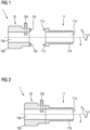
- Fig. 1 shows a longitudinal section through a media guide coupling 1 according to the invention according to a first embodiment in the separated state.
- Fig. 2 shows the representation of the Figure 1 in the connected state.
- the media guide coupling 1 is considered using the example of a hose coupling 1 in the form of a quick coupling 1.
- the hose coupling 1 has a first coupling element 10 with a flow opening 10a through which a medium such as in particular a fluid can flow along the longitudinal direction X.
- the first coupling element 10 has a first connecting element 10b and opposite it an inwardly directed second connecting element 10c.
- the first coupling element 10 also has a sensor receptacle 10d which is radially accessible from the outside and protrudes like a pin radially inwards into the flow opening 10a.
- the hose coupling 1 further comprises a second coupling element 11 with a flow opening 11a through which the fluid can flow along the longitudinal direction X.
- the second coupling element 11 comprises a first connecting element 11b and oppositely an inwardly directed second connecting element 11c.
- the two coupling elements 10, 11 are each manufactured separately as an injection-molded part, with the second coupling element 11 being designed as a fiber-reinforced injection-molded part. Both coupling elements 10, 11 can be connected in a fluid-tight manner to another media-conducting device 2, such as a hose 2, a pipe 2 or an aggregate, by means of their respective first connecting element 10b, 11b.
- Various mechanical connection mechanisms such as latches, clips or Screws can be used, especially in combination with an intermediate sealing element such as an O-ring.
- Both coupling elements 10, 11 can be connected to each other in a fixed and fluid-tight manner by means of their corresponding second connecting elements 10c, 11c, see Figure 2 so that the respective flow openings 10a, 11a of the coupling elements 10, 11 form a common flow opening 10a, 11a of the hose coupling 1.
- various mechanical connection mechanisms such as catches, clips or screws can also be used, in particular in combination with an intermediate sealing element such as an O-ring.
- the two coupling elements 10, 11 can be provided in different designs with regard to their first connecting elements 10b, 11b, so that the appropriate variant for the respective further media-carrying devices 2 can be selected from a large number of variants of first coupling elements 10 and second coupling elements 11 depending on the application.
- the first coupling element 10 can be adapted to the sensor 3 to be used with regard to its sensor holder 10d.
- the two selected coupling elements 10, 11 can then be connected to one another in a fixed and fluid-tight manner by means of their corresponding second connecting elements 10c, 11c in order to form the hose coupling 1.
- the hose coupling 1 can therefore also be referred to as a modular hose coupling 1.
- a hose coupling 1 can be created easily, flexibly and quickly, which is adapted to the respective application.
- an adaptation to the sensor 3 to be used can also be made.
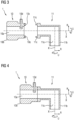
- Fig. 3 shows a longitudinal section through a media guide coupling 1 according to the invention according to a second embodiment in the separated state.
- Fig. 4 shows the representation of the Figure 3 in the connected state.
- a right-angled coupling element 11 is used as the second coupling element 11 instead of a straight coupling element 11, as is the case in the first embodiment.
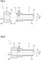
- Fig. 5 shows a longitudinal section through a media guide coupling 1 according to the invention according to a third embodiment in the separated state.
- Fig. 6 shows the representation of the Figure 5 in the connected state.
- the third embodiment corresponds to the first embodiment with the difference that the second coupling element 11 now has a sensor receptacle 11d.
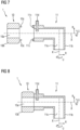
- Fig. 7 shows a longitudinal section through a media guide coupling 1 according to the invention according to a fourth embodiment in the separated state.
- Fig. 8 shows the representation of the Figure 7 in the connected state.
- the fourth embodiment represents a combination of the second and third embodiments.
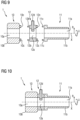
- Fig. 9 shows a longitudinal section through a media guide coupling 1 according to the invention according to a fifth embodiment in the separated state.
- Fig. 10 shows the representation of the Figure 9 in the connected state.
- the two coupling elements 10, 11 do not have any sensor receptacles 10d, 11d.
- the modular hose coupling 1 is designed in three parts, in that a corresponding sensor element 12 is arranged along the longitudinal axis X between the two external coupling elements 10, 11.
- the sensor element 12 has a corresponding flow opening 12a and a first Connecting element 12b and to the right a second connecting element 12c to be connected to the second connecting elements 10c, 11c of the two coupling elements 10, 11 as previously described.
- the sensor element 12 also has a sensor receptacle 12d.
- the two coupling elements 10, 11 can be selected to match the respective other media-carrying devices 2 depending on the application.
- the sensor element 12 can also be selected to match the respective sensor 3. This can simplify or expand the modularity options.
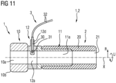
- Fig. 11 shows a longitudinal section through a media guide 1, 2 according to the invention with the media guide coupling 1 of the fifth embodiment.
- a hose 2 as the second media-conducting device 2 or its wall 20 is pulled over the first connecting element 11b of the second coupling element 11 and thus connected to the first connecting element 11b of the second coupling element 11, so that a flow opening 21 of the hose 2 coincides with the flow opening 10a, 11a, 12a of the hose coupling 1.
- a sensor 3 in the form of a temperature sensor 3 is received by the sensor receptacle 12d of the sensor element 12.
- a sensor probe 31 in the form of an NTC thermistor 31 projects all the way inwards or downwards into the sensor receptacle 12d and is held by a sensor housing 30 and connected to a sensor cable 32 in order to make the sensor values available to the outside.
Landscapes
- Engineering & Computer Science (AREA)
- General Engineering & Computer Science (AREA)
- Mechanical Engineering (AREA)
- Physics & Mathematics (AREA)
- General Physics & Mathematics (AREA)
- Quick-Acting Or Multi-Walled Pipe Joints (AREA)
Description
- Die vorliegende Erfindung betrifft eine Medienführungskupplung.
- Zum Transport bzw. zur Führung von Medien wie insbesondere von Fluiden ist die Verwendung von Schläuchen und Rohren bekannt, welche gemeinsam auch als Medienführungen bezeichnet werden können. Schläuche werden dabei als eher flexibel hinsichtlich ihres Materials angesehen, Rohre als eher starr. Zu den Fluiden gehören neben Flüssigkeiten auch Gase und pastöse Stoffe.
- Mehrere Schläuche können dabei untereinander mittels Schlauchkupplungen miteinander verbunden werden, welche jeweils an dem entsprechenden offenen Ende fest an dem jeweiligen Schlauch angeordnet sind. Über derartige Schlauchkupplungen können Schläuche ebenfalls mit Aggregaten verbunden werden, welche ihrerseits eine entsprechende Kupplung aufweisen. Derartige Schlauchkupplungen können als sogenannte Schnellkupplungen, im Englischen als Quick Connector bezeichnet, ausgebildet sein, welche ein schnelles und einfaches Verbinden und zerstörungsfreies Lösen ermöglichen können. Derartige Schlauchkupplungen können aus Metall aber auch aus Kunststoff, insbesondere als Spritzgussteile, ausgebildet sein. Dies gilt vergleichbar für Rohre. Entsprechend können derartige Schlauch- oder Rohrkupplungen auch gemeinsam als Medienführungskupplungen bezeichnet werden.
- Für viele Anwendungen kann es sinnvoll oder sogar erforderlich sein, die Temperatur des strömenden Mediums sensorisch zu erfassen. Hierzu ist es beispielsweise bekannt, einen Temperatursensor, üblicherweise in Form eines NTC-Thermistors (Heißleiter mit negativem Temperaturkoeffizienten), in eine Öffnung einer Schnellkupplung einzusetzen. Das Sensorelement bzw. der Messwertumformer des NTC-Thermistors ragt dabei durch eine Durchgangsöffnung der Schnellkupplung in das Medium hinein und hat somit direkten Kontakt zum Medium, was die Temperaturübertragung von Medium zu Messwertumformer begünstigen, d.h. die Ansprechzeit des NTC-Thermistors geringhalten kann.
- Nachteilig ist hierbei, dass die Durchgangsöffnung durch die Schnellkupplung hindurch, welche der Aufnahme und Durchführung des Messwertumformers des NTC-Thermistors dient, mit aufgenommenem Messwertumformer mediendicht abzuschließen ist. Entsprechend sind Maßnahmen zu treffen, um die Dichtigkeit am Anschluss des Messwertumformers herzustellen. Diese Maßnahmen können mit höheren Kosten für zusätzliche Komponenten und dem Risiko von verbleibenden Undichtigkeiten verbunden sein.
- Nachteilig ist ferner, dass beim Austausch des Messwertumformers, beispielsweise im Falle eines Defekts, ein umfangreicher Arbeitsaufwand anfallen kann. Durch die Tatsache, dass bei einer Demontage der entnommene Messwertumformer eine offene Durchgangsöffnung in das Innere der Schnellkupplung hinterlässt, muss vor dem Austausch des Messwertumformers das Medium aus dem System entfernt werden.
- Alternativ ist daher bekannt, in der Schnellkupplung eine Mulde vorzusehen, welche orthogonal zum Fluss des Mediums angebracht ist. Mit anderen Worten ist für den Messwertumformer des NTC-Thermistors keine Durchgangsöffnung vorhanden, so dass die entsprechenden zuvor beschriebenen Nachteile vermieden werden können. Stattdessen ist der Messwertumformer des NTC-Thermistors in der Mulde der Schnellkupplung angeordnet und ragt somit, durch das Material der Schnellkupplung muldenförmig umgeben, in das Medium hinein, ohne mit dem Medium in direkten Kontakt zu kommen.
- In jedem Fall können Temperatursensoren durch invasive Lösungen in Kunststoff-Spritzgussteile integriert werden. Diese Lösungen können aus zwei verschiedenen Teilen bestehen, bei denen eine Schlauchkupplung und die eingehausten Temperatursensoren beim Anwender auf das endgültige Teil montiert werden.
- Andere Ansätze bestehen darin, den Temperatursensor beispielsweise als NTC-Thermistor (Negative Temperature Coefficient Thermistor) direkt in ein Spritzgussteil zu integrieren, welches die Schlauchkupplung bildet. Dabei stellt das Gehäuse des Temperatursensors einen Anschluss der Schlauchkupplung dar, der innerhalb einer medienführenden Schlauchleitung montiert wird.
- Nachteilig ist hierbei, dass die Spritzgussteile der Schlauchkupplungen für die Integration eines Temperatursensors individuell gestaltet werden müssen. Dies stellt einen zusätzlichen Aufwand dar. Insbesondere kann sich hierdurch die Teilevielfalt deutlich erhöhen, wenn unterschiedliche Temperatursensoren verwendet werden können sollen.
- Nachteilig ist auch, dass dies die Verwendung neuer Materialien z. B. PA66 bei derartigen Schlauchkupplungen mit Temperatursensoren erschweren kann. Insbesondere sollten lediglich Materialien ohne Glasfaserverstärkung für derartige Anwendungen verwendet werden, da die Glasfasern die thermische Leitfähigkeit des Materials reduzieren und somit die Ansprechzeit und Genauigkeit des Temperatursensors verringern können. Entsprechend steht die Verwendung von Temperatursensoren im Widerspruch zur erhöhten Festigkeit derartiger Schlauchkupplungen, welche durch die Verwendung von glasfaserverstärktem Kunststoff erreicht werden kann. Die Dokumente
EP 2 531 767 B1 ,WO 2020/244842 A1 undUS 2017/045173 A1 betreffen Medienführungskupplungen aus dem Stand der Technik. - Eine Aufgabe der vorliegenden Erfindung ist es, eine Medienführungskupplung und insbesondere eine Schnellkupplung für Schläuche und bzw. oder Rohre der eingangs beschriebenen Art bereit zu stellen, so dass die Nachteile bekannter derartiger Medienführungskupplungen behoben oder zumindest reduziert werden können. Insbesondere soll eine Medienführungskupplung geschaffen werden, welche hinsichtlich der Versendung eines Sensors einfacher, schneller, kostengünstiger und bzw. oder flexibler an verschiedene Anwendungen angepasst werden kann. Dies soll insbesondere möglichst einfach, kompakt, kostengünstig, flexibel anwendbar und bzw. oder intuitiv umsetzbar erfolgen. Zumindest soll eine Alternative zu bekannten derartigen Medienführungskupplungen geschaffen werden.
- Die Aufgabe wird erfindungsgemäß durch eine Medienführungskupplung mit den Merkmalen der unabhängigen Patentansprüche 1 und 4 sowie durch eine Medienführung nach Anspruch 9 gelöst. Vorteilhafte Weiterbildungen sind in den Unteransprüchen beschrieben Somit betrifft die vorliegende Erfindung eine Medienführungskupplung mit einem ersten Kupplungselement mit einer Durchflussöffnung zur Führung eines Mediums durch sich hindurch, und mit einem ersten Verbindungselement zur Verbindung mit einer zweiten medienführenden Vorrichtung, vorzugsweise mit einem Schlauch, Rohr oder Aggregat, und mit einem zweiten Kupplungselement mit einer Durchflussöffnung zur Führung des Mediums durch sich hindurch, und mit einem ersten Verbindungselement zur Verbindung mit einer dritten medienführenden Vorrichtung, vorzugsweise mit einem Schlauch, Rohr oder Aggregat, wobei die beiden Kupplungselemente derart mediendicht miteinander verbunden sind, so dass ihre Durchflussöffnungen eine gemeinsame Durchflussöffnung der Medienführungskupplung bilden, und wobei das erste Kupplungselement eine Sensoraufnahme und bzw. oder das zweite Kupplungselement eine Sensoraufnahme aufweist.
- Der vorliegenden Erfindung liegt, wie eingangs beschrieben, die Erkenntnis zugrunde, dass es bisher aufwendig ist und zu einer entsprechenden Teilevielfalt führen kann, Sensoren wie insbesondere Temperatursensoren auf Medienführungskupplungen wie beispielsweise Schlauch- oder Rohrkupplungen anzuwenden. Schließlich sind derartige Medienführungskupplungen sowohl auf der einen Seite als auch auf der anderen gegenüberliegenden Seite je nach Anwendung an verschiedene andere medienführende Vorrichtungen wie Schläuche, Rohre, Aggregate und dergleichen anzuschließen und entsprechend passend auszubilden. Ferner sind unterschiedliche Sensoren hinsichtlich Typ, Hersteller, Baugröße und dergleichen zu verwenden.
- Erfindungsgemäß wird daher zum einen eine Medienführungskupplung mit und vorzugsweise bestehend aus zwei Kupplungselementen ausgebildet, wobei die beiden Kupplungselemente jeweils passend zu einer von vielen verschiedenen medienführenden Vorrichtungen ausgebildet sein können. Entsprechend können je nach Anwendungsfall, d.h. je nach zu verbindenden medienführenden Vorrichtungen, zwei jeweils passende Kupplungselemente ausgewählt und zu einer erfindungsgemäßen Medienführungskupplung verbunden werden. Die beiden Kupplungselemente könne somit separat hergestellt werden, was die Teilevielhaft reduziert. Dies kann die Herstellungskosten reduzieren.
- Dabei eine Sensoraufnahme bei wenigstens einer der beiden Kupplungselemente vorzusehen kann zusätzlich die Möglichkeit schaffen, einen Sensor zu verwenden. Entsprechend kann das entsprechende Kupplungselement ferner für unterschiedliche Sensoren ausgelegt sein und je nach Anwendungsfall mit dem anderen Kupplungselement verbunden werden. Auch dies kann die Teilevielhaft reduzieren.
- Somit können erfindungsgemäß die Anpassungen einer Medienführungskupplung an einen neuen Anwendungsfall dahingehend reduziert werden, dass vorhandene bzw. bereits konstruierte Kupplungselemente lediglich neu miteinander kombiniert werden müssen, was den Aufwand der Anpassung geringhalten und ggfs. einen Konstruktionsaufwand überflüssig machen kann. Ggfs. können erforderliche Anpassungen auf lediglich eines der beiden Kupplungselemente beschränkt werden, was ebenfalls zu einer Reduzierung des Aufwand führen kann. In jedem Fall kann eine zweiteilige Modularität einer Medienführungskupplung ermöglicht werden.
- Die gilt zum anderen entsprechend für eine Anordnung mit zwei Kupplungselementen und einem dazwischenliegenden Sensorelement mit einer Sensoraufnahme, wie weiter unten näher erläutert werden wird.
- Die Erfindung ist einsetzbar für jegliche Anwendungen, bei denen die Temperatur des Mediums innerhalb einer Medienführung wie insbesondere innerhalb eines Schlauch- oder Rohrsystems gemessen werden soll. Als Anwendung ist insbesondere die Temperaturmessung von Kühlmitteln in batterieelektrischen Fahrzeugen denkbar.
- Gemäß der Erfindung weist das erste Kupplungselement ein zweites Verbindungselement auf, weist das zweite Kupplungselement ein zweites Verbindungselement auf und das erste Kupplungselement und das zweite Kupplungselement mittels ihrer zweiten Verbindungselemente, mittels Rasten, Klipsen oder Schrauben, mediendicht miteinander verbunden sind. Hierdurch können die entsprechenden Eigenschaften und Vorteile auf die erfindungsgemäße Medienführungskupplung angewendet werden.
- Gemäß einem weiteren Aspekt der Erfindung ist zwischen den beiden zweiten Verbindungselementen ein Dichtungselement, vorzugsweise ein O-Ring, angeordnet. Hierdurch können die entsprechenden Eigenschaften und Vorteile auf die erfindungsgemäße Medienführungskupplung angewendet werden.
- Gemäß einem weiteren Aspekt der Erfindung ist das Kupplungselement ohne Sensoraufnahme als faserverstärktes Spritzgussteil ausgebildet. Hierdurch können die entsprechenden Eigenschaften und Vorteile auf die erfindungsgemäße Medienführungskupplung angewendet werden. Insbesondere können die strukturverstärkenden Eigenschaften von faserverstärkten Spritzgussteilen bei dem Kupplungselement ohne Sensoraufnahme genutzt werden und gleichzeitig die negativen Einflüsse einer Faserverstärkung bei dem Kupplungselement mit Sensoraufnahme vermieden werden.
- Die vorliegende Erfindung betrifft auch eine Medienführungskupplung mit einem ersten Kupplungselement mit einer Durchflussöffnung zur Führung eines Mediums durch sich hindurch, und mit einem ersten Verbindungselement zur Verbindung mit einer zweiten medienführenden Vorrichtung, vorzugsweise mit einem Schlauch, Rohr oder Aggregat, mit einem zweiten Kupplungselement mit einer Durchflussöffnung zur Führung des Mediums durch sich hindurch, und mit einem ersten Verbindungselement zur Verbindung mit einer dritten medienführenden Vorrichtung, vorzugsweise mit einem Schlauch, Rohr oder Aggregat, und mit einem Sensorelement mit einer Durchflussöffnung zur Führung des Mediums durch sich hindurch, wobei das erste Kupplungselement mit dem Sensorelement und das Sensorelement mit dem zweiten Kupplungselement derart mediendicht miteinander verbunden sind, so dass ihre Durchflüsse einen gemeinsamen Durchflussöffnung der Medienführungskupplung bilden, und wobei das Sensorelement eine Sensoraufnahme aufweist.
- Auf diese Art und Weise können die zuvor beschriebene Aspekte, Eigenschaften und Vorteile der vorliegenden Erfindung auch auf eine dreigeteilte Medienführungskupplung angewendet werden, indem die beiden außenliegenden Kupplungselemente zu den jeweiligen verschiedenen anderen medienführenden Vorrichtungen passend ausgebildet und verwendet sowie mittels des Sensorelements miteinander verbunden werden können, welche ihrerseits passend zum zu verwendenden Sensor ausgebildet bzw. ausgewählt werden kann. Dies kann die Umsetzung einer dreiteiligen Modularität ermöglichen.
- Gemäß der Erfindung weist bzw. weisen das erste Kupplungselement und bzw. oder das zweite Kupplungselement ein zweites Verbindungselement auf, wobei das Sensorelement ein erstes Verbindungselement, vorzugweise und ein zweites Verbindungselement, aufweist, und wobei das erste Kupplungselement und bzw. oder das zweite Kupplungselement mittels ihrer zweiten Verbindungselemente, mittels Rasten, Klipsen oder Schrauben, mediendicht mit dem Verbindungselement(en) des Sensorelements verbunden sind. Hierdurch können die entsprechenden Eigenschaften und Vorteile auf die erfindungsgemäße Medienführungskupplung angewendet werden.
- Gemäß einem weiteren Aspekt der Erfindung ist zwischen den Verbindungselementen (jeweils) ein Dichtungselement, vorzugsweise ein O-Ring, angeordnet. Hierdurch können die entsprechenden Eigenschaften und Vorteile auf die erfindungsgemäße Medienführungskupplung angewendet werden.
- Gemäß einem weiteren Aspekt der Erfindung ist bzw. sind das erste Kupplungselement und bzw. oder das zweite Kupplungselement als faserverstärktes Spritzgussteil ausgebildet. Hierdurch können die entsprechenden Eigenschaften und Vorteile auf die erfindungsgemäße Medienführungskupplung angewendet werden.
- Gemäß einem weiteren Aspekt der Erfindung sind das erste Verbindungselement des ersten Kupplungselements und das erste Verbindungselement des zweiten Kupplungselements mit gleichen oder unterschiedlichen Verbindungsmechanismen ausgebildet. Hierdurch können die entsprechenden Eigenschaften und Vorteile auf die erfindungsgemäße Medienführungskupplung angewendet werden.
- Gemäß einem weiteren Aspekt der Erfindung ragt die Sensoraufnahme wenigstens abschnittsweise, vorzugsweise vollständig, vorzugsweise senkrecht zur Durchflussöffnung, in die Durchflussöffnung hinein. Dies kann die Kontaktfläche zwischen der Sensoraufnahme und damit auch einem von der Sensoraufnahme aufgenommenen Sensor vergrößern und damit auch die sensorische wie beispielsweise thermische Übertragung zwischen dem Medium und dem Sensor verbessern
- Die vorliegende Erfindung betrifft ferner eine Medienführung mit einer Medienführungskupplung wie zuvor beschrieben und mit einer zweiten medienführenden Vorrichtung, vorzugsweise mit einem Schlauch, Rohr oder Aggregat. Eine Medienführung kann somit beispielsweise eine Schlauch- oder Rohranwendung sein, welche einen Schlauch oder ein Rohr als zweite medienführende Vorrichtung bzw. als eigentliche Medienführung sowie eine hiermit fest und mediendicht verbundene Medienführungskupplung mit beispielsweise einer Schlauch- oder Rohrkupplung sein. Hierdurch kann die erfindungsgemäße Medienführungskupplung umgesetzt und angewendet werden, um dessen Eigenschaften und Vorteile nutzen zu können.
- Mit anderen Worten ist die Lösung Teil eines modularen Schnellverbinders, bei dem die Sensor- und insbesondere die Temperaturmessfunktion durch die Integration eines, vorzugsweise zylindrischen, Teils in der Mitte oder am Ende des Schnellverbinders realisiert wird, an dem ein Temperatursensor befestigt oder direkt eingebaut werden kann. Durch die Verwendung einer solchen Lösung kann beispielsweise eine hohe Wärmeleitfähigkeit erreicht werden, ohne dass die vorhandenen Werkzeuge verändert werden müssen. Auch kann die Herstellung eines solchen beispielsweise temperatursensitiven Schnellverbinders nur eine kleine Anpassung des Prozesses erfordern. Die Lösung kann auch ein vergleichsweise kleines Volumen ermöglichen und in jedes Gerät eingebaut werden, welches modular aufgebaut ist. Die Lösung kann auch ein, vorzugsweise zylindrisches, Teil sein, welches beispielsweise auf jeden vorhandenen Schnellanschluss auf der einen Seite eines männlichen und auf der anderen Seite eines weiblichen Verbindungselements montiert werden kann. Dies kann eine höhere Flexibilität bei der Anwendung in derzeit verwendeten Mediensystemen ermöglichen. Diese Lösung, beispielsweise als Sensorring, kann für die Testphase eines Prototyps oder als nachrüstbare Sensoranpassung verwendet werden.
- Mehrere Ausführungsbeispiele und weitere Vorteile der Erfindung werden nachstehend im Zusammenhang mit den folgenden Figuren erläutert. Darin zeigt:
- Fig. 1
- einen Längsschnitt durch eine erfindungsgemäße Medienführungskupplung gemäß eines ersten Ausführungsbeispiels im getrennten Zustand;
- Fig. 2
- die Darstellung der
Figur 1 im verbundenen Zustand; - Fig. 3
- einen Längsschnitt durch eine erfindungsgemäße Medienführungskupplung gemäß eines zweiten Ausführungsbeispiels im getrennten Zustand;
- Fig. 4
- die Darstellung der
Figur 3 im verbundenen Zustand; - Fig. 5
- einen Längsschnitt durch eine erfindungsgemäße Medienführungskupplung gemäß eines dritten Ausführungsbeispiels im getrennten Zustand;
- Fig. 6
- die Darstellung der
Figur 5 im verbundenen Zustand; - Fig. 7
- einen Längsschnitt durch eine erfindungsgemäße Medienführungskupplung gemäß eines vierten Ausführungsbeispiels im getrennten Zustand;
- Fig. 8
- die Darstellung der
Figur 7 im verbundenen Zustand; - Fig. 9
- einen Längsschnitt durch eine erfindungsgemäße Medienführungskupplung gemäß eines fünften Ausführungsbeispiels im getrennten Zustand;
- Fig. 10
- die Darstellung der
Figur 9 im verbundenen Zustand; und - Fig. 11
- einen Längsschnitt durch eine erfindungsgemäße Medienführung mit der Medienführungskupplung des fünften Ausführungsbeispiels.
- Die Beschreibung der o.g. Figuren erfolgt in zylindrischen Koordinaten mit einer Längsachse X, einer zur Längsachse X senkrecht ausgerichteten radialen Richtung R sowie einer um die Längsachse X umlaufenden Umfangsrichtung U. Die Längsachse X, die radiale Richtung R und die Umfangsrichtung U können gemeinsam auch als Raumrichtungen X, R, U bzw. als zylindrische Raumrichtungen X, R, U bezeichnet werden.
-
Fig. 1 zeigt einen Längsschnitt durch eine erfindungsgemäße Medienführungskupplung 1 gemäß eines ersten Ausführungsbeispiels im getrennten Zustand.Fig. 2 zeigt die Darstellung derFigur 1 im verbundenen Zustand. Die Medienführungskupplung 1 wird am Beispiel einer Schlauchkupplung 1 in Form einer Schnellkupplung 1 betrachtet. - Die Schlauchkupplung 1 weist ein erstes Kupplungselement 10 mit einer Durchflussöffnung 10a auf, durch welche hindurch ein Medium wie insbesondere ein Fluid entlang der Längsrichtung X strömen kann. Entlang der Längsachse X nach links und somit nach außen gerichtet weist das erste Kupplungselement 10 ein erstes Verbindungselement 10b und gegenüberliegend ein nach innen gerichtetes zweites Verbindungselement 10c auf. Radial ausgerichtet weist das erste Kupplungselement 10 ferner eine Sensoraufnahme 10d auf, welche radial von außen zugänglich ist und stiftartig radial nach innen in die Durchflussöffnung 10a hineinragt.
- Die Schlauchkupplung 1 weist ferner ein zweites Kupplungselement 11 mit einer Durchflussöffnung 11a auf, durch welche hindurch das Fluid entlang der Längsrichtung X strömen kann. Entlang der Längsachse X nach rechts und somit nach außen gerichtet weist das zweite Kupplungselement 11 ein erstes Verbindungselement 11b und gegenüberliegend ein nach innen gerichtetes zweites Verbindungselement 11c auf.
- Die beiden Kupplungselemente 10, 11 sind jeweils als Spritzgussteil separat hergestellt, wobei das zweite Kupplungselement 11 als faserverstärktes Spritzgussteil ausgebildet ist. Beide Kupplungselemente 10, 11 können mittels ihres jeweiligen ersten Verbindungselements 10b, 11b jeweils mit einer weiteren medienführenden Vorrichtung 2 wie beispielsweise einem Schlauch 2, einem Rohr 2 bzw. einem Aggregat fluiddicht verbunden werden. Hierzu können verschiedene mechanische Verbindungsmechanismen wie beispielsweise Rasten, Klipsen oder Schrauben verwendet werden, insbesondere in Kombination mit einem dazwischenliegenden Dichtelement wie beispielsweise einem O-Ring.
- Beide Kupplungselemente 10, 11 können mittels ihrer korrespondierenden zweiten Verbindungselemente 10c, 11c feststehend und fluiddicht miteinander verbunden werden, siehe
Figur 2 , so dass die jeweiligen Durchflussöffnungen 10a, 11a der Kupplungselemente 10, 11 eine gemeinsame Durchflussöffnung 10a, 11a der Schlauchkupplung 1 bilden. Hierzu können ebenfalls verschiedene mechanische Verbindungsmechanismen wie beispielsweise Rasten, Klipsen oder Schrauben verwendet werden, insbesondere in Kombination mit einem dazwischenliegenden Dichtelement wie beispielsweise einem O-Ring. - Die beiden Kupplungselemente 10, 11 können in unterschiedlicher Ausgestaltung hinsichtlich ihrer ersten Verbindungselemente 10b, 11b vorliegen, so dass jeweils aus einer Vielzahl von Varianten erster Kupplungselemente 10 und zweiter Kupplungselemente 11 die passende Variante für die jeweiligen weiteren medienführenden Vorrichtungen 2 je nach Anwendungsfall ausgewählt werden kann. Ferner kann das erste Kupplungselement 10 hinsichtlich seiner Sensoraufnahme 10d an den zu verwendenden Sensor 3 angepasst sein. Dann können die beiden ausgewählten Kupplungselemente 10, 11 mittels ihrer korrespondierenden zweiten Verbindungselemente 10c, 11c feststehend und fluiddicht miteinander verbunden werden, um die Schlauchkupplung 1 zu bilden. Die Schlauchkupplung 1 kann daher auch als modulare Schlauchkupplung 1 bezeichnet werden.
- Auf diese Art und Weise kann einfach, flexibel und schnell eine Schlauchkupplung 1 geschaffen werden, welche an den jeweiligen Anwendungsfall angepasst ist. Gleichzeitig kann auch eine Anpassung an den zu verwendenden Sensor 3 erfolgen.
-
Fig. 3 zeigt einen Längsschnitt durch eine erfindungsgemäße Medienführungskupplung 1 gemäß eines zweiten Ausführungsbeispiels im getrennten Zustand.Fig. 4 zeigt die Darstellung derFigur 3 im verbundenen Zustand. In diesem Fall wird als zweites Kupplungselement 11 ein rechtwinkeliges Kupplungselement 11 anstelle eines geradlinigen Kupplungselements 11 verwendet, wie es bei dem ersten Ausführungsbeispiel der Fall ist. -
Fig. 5 zeigt einen Längsschnitt durch eine erfindungsgemäße Medienführungskupplung 1 gemäß eines dritten Ausführungsbeispiels im getrennten Zustand.Fig. 6 zeigt die Darstellung derFigur 5 im verbundenen Zustand. Das dritte Ausführungsbeispiel entspricht dem ersten Ausführungsbeispiel mit dem Unterschied, dass nun das zweite Kupplungselement 11 eine Sensoraufnahme 11d aufweist. -
Fig. 7 zeigt einen Längsschnitt durch eine erfindungsgemäße Medienführungskupplung 1 gemäß eines vierten Ausführungsbeispiels im getrennten Zustand.Fig. 8 zeigt die Darstellung derFigur 7 im verbundenen Zustand. Das vierte Ausführungsbeispiel stellt eine Kombination des zweiten und dritten Ausführungsbeispiels dar. -
Fig. 9 zeigt einen Längsschnitt durch eine erfindungsgemäße Medienführungskupplung 1 gemäß eines fünften Ausführungsbeispiels im getrennten Zustand.Fig. 10 zeigt die Darstellung derFigur 9 im verbundenen Zustand. - In diesem Fall weisen die beiden Kupplungselemente 10, 11 keine Sensoraufnahmen 10d, 11d auf. Vielmehr ist die modulare Schlauchkupplung 1 dreiteilig ausgebildet, indem entlang der Längsachse X zwischen den beiden außenseitigen Kupplungselementen 10, 11 ein korrespondierendes Sensorelement 12 angeordnet ist. Das Sensorelement 12 weist eine entsprechende Durchflussöffnung 12a sowie nach links ein ersten Verbindungselement 12b und nach rechts ein zweites Verbindungselement 12c auf, um mit den zweiten Verbindungselementen 10c, 11c der beiden Kupplungselemente 10, 11 wie zuvor beschrieben verbunden zu werden. Auch weist das Sensorelement 12 eine Sensoraufnahme 12d auf.
- Entsprechend können die beiden Kupplungselemente 10, 11 je nach Anwendungsfall zu den jeweiligen weiteren medienführenden Vorrichtungen 2 passend ausgewählt werden. Ebenso kann das Sensorelement 12 passend zum jeweiligen Sensor 3 ausgewählt werden. Dies kann die Möglichkeiten der Modularität vereinfachen bzw. erweitern.
-
Fig. 11 zeigt einen Längsschnitt durch eine erfindungsgemäße Medienführung 1, 2 mit der Medienführungskupplung 1 des fünften Ausführungsbeispiels. Es ist ein Schlauch 2 als zweite medienführende Vorrichtung 2 bzw. dessen Wandung 20 über das erste Verbindungselement 11b des zweiten Kupplungselements 11 übergezogen und so mit dem ersten Verbindungselement 11b des zweiten Kupplungselements 11 verbunden, so dass eine Durchflussöffnung 21 des Schlauches 2 mit der Durchflussöffnung 10a, 11a, 12a der Schlauchkupplung 1 zusammenfällt. Ferner wird ein Sensor 3 in Form eines Temperatursensors 3 von der Sensoraufnahme 12d des Sensorelements 12 aufgenommen. Ein Sensorfühler 31 in Form eines NTC-Thermistors 31 ragt dabei bis ganz nach innen bzw. unten in die Sensoraufnahme 12d hinein und wird von einem Sensorgehäuse 30 gehalten sowie mit einem Sensorkabel 32 verbunden, um die Sensorwerte nach außerhalb zur Verfügung zu stellen. -
- R
- radiale Richtung
- U
- Umfangsrichtung
- X
- Längsrichtung
- 1, 2
- Medienführung; Schlauchleitung; Rohrleitung
- 1
- Medienführungskupplung; Schlauchkupplung; Schnellkupplung
- 10
- erstes Kupplungselement
- 10a
- Durchflussöffnung des ersten Kupplungselements 10
- 10b
- erstes Verbindungselement des ersten Kupplungselements 10
- 10c
- zweites Verbindungselement des ersten Kupplungselements 10
- 10d
- Sensoraufnahme des ersten Kupplungselements 10
- 11
- zweites Kupplungselement
- 11a
- Durchflussöffnung des zweiten Kupplungselements 11
- 11b
- erstes Verbindungselement des zweiten Kupplungselements 11
- 11c
- zweites Verbindungselement des zweiten Kupplungselements 11
- 11d
- Sensoraufnahme des zweiten Kupplungselements 11
- 12
- Sensorelement; Sensorbereich
- 12a
- Durchflussöffnung des Sensorelements 12
- 12b
- erstes Verbindungselement des Sensorelements 12
- 12c
- zweites Verbindungselement des Sensorelements 12
- 12d
- Sensoraufnahme des Sensorelements 12
- 2
- zweite medienführende Vorrichtung; Schlauch; Rohr
- 20
- Wandung des Schlauches 2; Schlauchwand; Rohrwand
- 21
- Durchflussöffnung
- 3
- Sensor; Temperatursensor
- 30
- Sensorgehäuse
- 31
- Sensorfühler; NTC-Thermistor
- 32
- Sensorkabel
Claims (9)
- Medienführungskupplung (1)mit einem ersten Kupplungselement (10)mit einer Durchflussöffnung (10a) zur Führung eines Mediums durch sich hindurch, undmit einem ersten Verbindungselement (10b) zur Verbindung mit einer zweiten medienführenden Vorrichtung (2), vorzugsweise mit einem Schlauch (2), Rohr (2) oder Aggregat, undmit einem zweiten Kupplungselement (11)mit einer Durchflussöffnung (11a) zur Führung des Mediums durch sich hindurch, undmit einem ersten Verbindungselement (11b) zur Verbindung mit einer dritten medienführenden Vorrichtung, vorzugsweise mit einem Schlauch, Rohr oder Aggregat,wobei die beiden Kupplungselemente (10, 11) derart mediendicht miteinander verbunden sind, so dass ihre Durchflussöffnungen (10a, 11a) eine gemeinsame Durchflussöffnung (10a, 11a) der Medienführungskupplung (1) bilden, undwobei das erste Kupplungselement (10) eine Sensoraufnahme (10d) und/oder das zweite Kupplungselement (11) eine Sensoraufnahme (11d) aufweist,dadurch gekennzeichnet, dassdas erste Kupplungselement (10) ein zweites Verbindungselement (10c) aufweist,wobei das zweite Kupplungselement (11) ein zweites Verbindungselement (11c) aufweist, undwobei das erste Kupplungselement (10) und das zweite Kupplungselement (11) mittels ihrer zweiten Verbindungselemente (10c, 11c)mittels Rasten, Klipsen oder Schrauben, mediendicht miteinander verbunden sind.
- Medienführungskupplung (1) nach Anspruch 1,
wobei zwischen den beiden zweiten Verbindungselementen (10c, 11c) ein Dichtungselement, vorzugsweise ein O-Ring, angeordnet ist. - Medienführungskupplung (1) nach einem der vorangehenden Ansprüche, wobei das Kupplungselement (10, 11) ohne Sensoraufnahme (10d, 11d) als faserverstärktes Spritzgussteil ausgebildet ist.
- Medienführungskupplung (1)mit einem ersten Kupplungselement (10)mit einer Durchflussöffnung (10a) zur Führung eines Mediums durch sich hindurch, undmit einem ersten Verbindungselement (10b) zur Verbindung mit einer zweiten medienführenden Vorrichtung (2), vorzugsweise mit einem Schlauch (2), Rohr (2) oder Aggregat,mit einem zweiten Kupplungselement (11)mit einer Durchflussöffnung (11a) zur Führung des Mediums durch sich hindurch, undmit einem ersten Verbindungselement (11b) zur Verbindung mit einer dritten medienführenden Vorrichtung, vorzugsweise mit einem Schlauch, Rohr oder Aggregat, undmit einem Sensorelement (12)
mit einer Durchflussöffnung (12a) zur Führung des Mediums durch sich hindurch,wobei das erste Kupplungselement (10) mit dem Sensorelement (12) und das Sensorelement (12) mit dem zweiten Kupplungselement (11) derart mediendicht miteinander verbunden sind, so dass ihre Durchflüsse (10a, 11a, 12a) einen gemeinsamen Durchflussöffnung (10a, 11a, 12a) der Medienführungskupplung (1) bilden, undwobei das Sensorelement (12) eine Sensoraufnahme (12d) aufweist, dadurch gekennzeichnet, dassdas erste Kupplungselement (10) und/oder das zweite Kupplungselement (11) ein zweites Verbindungselement (10c, 11c) aufweist/ausweisen, wobei das Sensorelement (12) ein erstes Verbindungselement (12b), vorzugweise und ein zweites Verbindungselement (12c), aufweist, und wobei das erste Kupplungselement (10) und/oder das zweite Kupplungselement (11) mittels ihrer zweiten Verbindungselemente (10c, 11c)mittels Rasten, Klipsen oder Schrauben, mediendicht mit dem Verbindungselement(en) (12b, 12c) des Sensorelements (12) verbunden sind. - Medienführungskupplung (1) nach Anspruch 4,
wobei zwischen den Verbindungselementen (10c, 11c, 12b, 12c) (jeweils) ein Dichtungselement, vorzugsweise ein O-Ring, angeordnet ist. - Medienführungskupplung (1) nach einem der Ansprüche 4 bis 5,
wobei das erste Kupplungselement (10) und/oder das zweite Kupplungselement (11) als faserverstärktes Spritzgussteil ausgebildet ist/sind. - Medienführungskupplung (1) nach einem der vorangehenden Ansprüche, wobei das erste Verbindungselement (10b) des ersten Kupplungselements (10) und das erste Verbindungselement (11b) des zweiten Kupplungselements (11) mit gleichen oder unterschiedlichen Verbindungsmechanismen ausgebildet sind.
- Medienführungskupplung (1) nach einem der vorangehenden Ansprüche, wobei die Sensoraufnahme (10d, 11d, 12d) wenigstens abschnittsweise, vorzugsweise vollständig, vorzugsweise senkrecht zur Durchflussöffnung (10a, 11a, 12a), in die Durchflussöffnung (10a, 11a, 12a) hineinragt.
- Medienführung (1, 2)mit einer Medienführungskupplung (1) nach einem der vorangehenden Ansprüche undmit einer zweiten medienführenden Vorrichtung (2), vorzugsweise mit einem Schlauch (2), Rohr (2) oder Aggregat.
Applications Claiming Priority (1)
| Application Number | Priority Date | Filing Date | Title |
|---|---|---|---|
| DE102021213687.7A DE102021213687A1 (de) | 2021-12-02 | 2021-12-02 | Medienführungskupplung |
Publications (2)
| Publication Number | Publication Date |
|---|---|
| EP4191111A1 EP4191111A1 (de) | 2023-06-07 |
| EP4191111B1 true EP4191111B1 (de) | 2024-12-11 |
Family
ID=83898035
Family Applications (1)
| Application Number | Title | Priority Date | Filing Date |
|---|---|---|---|
| EP22201816.0A Active EP4191111B1 (de) | 2021-12-02 | 2022-10-17 | Medienführungskupplung und medienführung |
Country Status (2)
| Country | Link |
|---|---|
| EP (1) | EP4191111B1 (de) |
| DE (1) | DE102021213687A1 (de) |
Family Cites Families (3)
| Publication number | Priority date | Publication date | Assignee | Title |
|---|---|---|---|---|
| DE102010006766A1 (de) * | 2010-02-04 | 2011-08-04 | A. Raymond Et Cie | Fluidleitungselement |
| DE102014005817A1 (de) * | 2014-04-24 | 2015-10-29 | Voss Automotive Gmbh | Mehrteilige beheizbare Medienleitung, Leitungsverbindungseinrichtung für eine solche sowie Verfahren zum Herstellen einer solchen |
| DE102019208375A1 (de) * | 2019-06-07 | 2020-12-10 | CONTITECH KüHNER GMBH & CIE KG | Rohr mit Flansch |
-
2021
- 2021-12-02 DE DE102021213687.7A patent/DE102021213687A1/de active Pending
-
2022
- 2022-10-17 EP EP22201816.0A patent/EP4191111B1/de active Active
Also Published As
| Publication number | Publication date |
|---|---|
| DE102021213687A1 (de) | 2023-06-07 |
| EP4191111A1 (de) | 2023-06-07 |
Similar Documents
| Publication | Publication Date | Title |
|---|---|---|
| DE69634011T2 (de) | Verbindungsherstellung und herstellungsverfahren | |
| DE10029186C2 (de) | Temperatur-Messvorrichtung | |
| EP1169202B1 (de) | Anordnung zur messung eines fluiddrucks | |
| DE3903551C2 (de) | Verbindungsteil einer Leitungskupplung | |
| WO2014044499A1 (de) | Verbindungselement für einen beheizbaren schlauch | |
| EP3649392B1 (de) | Messrohr zur bestimmung und/oder überwachung zumindest einer prozessgrösse eines mediums | |
| DE112006003344T5 (de) | Anschluss für eine Kopplungsvorrichtung für Fluidtransfer | |
| EP0876564B1 (de) | Rohrverbinder | |
| EP4191111B1 (de) | Medienführungskupplung und medienführung | |
| EP2072967A1 (de) | Elektronischer Sensor und Verfahren zur Herstellung eines Sensors | |
| DE102008051303A1 (de) | Verschlusskupplung | |
| EP3591268B1 (de) | Fluidleitungsverbinder mit fixiertem einsatzteil zur drosslung | |
| DE102011088736A1 (de) | Einbauarmatur mit einer Dichtungsvorrichtung | |
| EP2895779B1 (de) | Vorrichtung zum verbinden von zwei fluid führenden leitungen | |
| DE202020106224U1 (de) | Sensorsystem | |
| EP4038352A1 (de) | Hygienegerechter adapter für feldgerät | |
| DE102018129781A1 (de) | Messrohr für ein Messgerät sowie Verfahren zu dessen Herstellung | |
| DE20318857U1 (de) | Fluidleitungsverbindungsanordnung | |
| DE102009017335A1 (de) | Vorrichtung zur Messung des Volumen- oder Massestromes eines Mediums, Maschine mit entsprechender Vorrichtung | |
| DE102014001640B4 (de) | Druck- und Temperatursensor-Element | |
| DE10227373B4 (de) | Rohrförmige Staudrucksonde | |
| EP4113082B1 (de) | Temperatursensor | |
| EP4399494B1 (de) | Durchflusseinrichtung zum anordnen an einer fluidführenden leitung und zum anbringen einer durchflussmesseinrichtung, verwendung einer durchflusseinrichtung | |
| EP2037161A1 (de) | Dichtung mit integriertem Sensor und Dichtungsanordnung mit dieser Dichtung | |
| DE10325426A1 (de) | Kupplungselement für Wellrohre |
Legal Events
| Date | Code | Title | Description |
|---|---|---|---|
| PUAI | Public reference made under article 153(3) epc to a published international application that has entered the european phase |
Free format text: ORIGINAL CODE: 0009012 |
|
| STAA | Information on the status of an ep patent application or granted ep patent |
Free format text: STATUS: THE APPLICATION HAS BEEN PUBLISHED |
|
| AK | Designated contracting states |
Kind code of ref document: A1 Designated state(s): AL AT BE BG CH CY CZ DE DK EE ES FI FR GB GR HR HU IE IS IT LI LT LU LV MC ME MK MT NL NO PL PT RO RS SE SI SK SM TR |
|
| STAA | Information on the status of an ep patent application or granted ep patent |
Free format text: STATUS: REQUEST FOR EXAMINATION WAS MADE |
|
| 17P | Request for examination filed |
Effective date: 20231207 |
|
| RBV | Designated contracting states (corrected) |
Designated state(s): AL AT BE BG CH CY CZ DE DK EE ES FI FR GB GR HR HU IE IS IT LI LT LU LV MC ME MK MT NL NO PL PT RO RS SE SI SK SM TR |
|
| GRAP | Despatch of communication of intention to grant a patent |
Free format text: ORIGINAL CODE: EPIDOSNIGR1 |
|
| STAA | Information on the status of an ep patent application or granted ep patent |
Free format text: STATUS: GRANT OF PATENT IS INTENDED |
|
| RIC1 | Information provided on ipc code assigned before grant |
Ipc: G01K 13/02 20210101ALI20240424BHEP Ipc: G01K 1/14 20210101ALI20240424BHEP Ipc: F16L 41/00 20060101ALI20240424BHEP Ipc: F16L 37/084 20060101ALI20240424BHEP Ipc: F16L 33/30 20060101ALI20240424BHEP Ipc: F16L 13/10 20060101ALI20240424BHEP Ipc: F16L 13/02 20060101AFI20240424BHEP |
|
| INTG | Intention to grant announced |
Effective date: 20240513 |
|
| P01 | Opt-out of the competence of the unified patent court (upc) registered |
Free format text: CASE NUMBER: APP_44358/2024 Effective date: 20240730 |
|
| GRAS | Grant fee paid |
Free format text: ORIGINAL CODE: EPIDOSNIGR3 |
|
| GRAA | (expected) grant |
Free format text: ORIGINAL CODE: 0009210 |
|
| STAA | Information on the status of an ep patent application or granted ep patent |
Free format text: STATUS: THE PATENT HAS BEEN GRANTED |
|
| AK | Designated contracting states |
Kind code of ref document: B1 Designated state(s): AL AT BE BG CH CY CZ DE DK EE ES FI FR GB GR HR HU IE IS IT LI LT LU LV MC ME MK MT NL NO PL PT RO RS SE SI SK SM TR |
|
| REG | Reference to a national code |
Ref country code: GB Ref legal event code: FG4D Free format text: NOT ENGLISH |
|
| REG | Reference to a national code |
Ref country code: CH Ref legal event code: EP |
|
| REG | Reference to a national code |
Ref country code: DE Ref legal event code: R096 Ref document number: 502022002366 Country of ref document: DE |
|
| REG | Reference to a national code |
Ref country code: IE Ref legal event code: FG4D Free format text: LANGUAGE OF EP DOCUMENT: GERMAN |
|
| REG | Reference to a national code |
Ref country code: LT Ref legal event code: MG9D |
|
| PG25 | Lapsed in a contracting state [announced via postgrant information from national office to epo] |
Ref country code: HR Free format text: LAPSE BECAUSE OF FAILURE TO SUBMIT A TRANSLATION OF THE DESCRIPTION OR TO PAY THE FEE WITHIN THE PRESCRIBED TIME-LIMIT Effective date: 20241211 |
|
| PG25 | Lapsed in a contracting state [announced via postgrant information from national office to epo] |
Ref country code: FI Free format text: LAPSE BECAUSE OF FAILURE TO SUBMIT A TRANSLATION OF THE DESCRIPTION OR TO PAY THE FEE WITHIN THE PRESCRIBED TIME-LIMIT Effective date: 20241211 |
|
| PG25 | Lapsed in a contracting state [announced via postgrant information from national office to epo] |
Ref country code: BG Free format text: LAPSE BECAUSE OF FAILURE TO SUBMIT A TRANSLATION OF THE DESCRIPTION OR TO PAY THE FEE WITHIN THE PRESCRIBED TIME-LIMIT Effective date: 20241211 |
|
| REG | Reference to a national code |
Ref country code: NL Ref legal event code: MP Effective date: 20241211 |
|
| PG25 | Lapsed in a contracting state [announced via postgrant information from national office to epo] |
Ref country code: ES Free format text: LAPSE BECAUSE OF FAILURE TO SUBMIT A TRANSLATION OF THE DESCRIPTION OR TO PAY THE FEE WITHIN THE PRESCRIBED TIME-LIMIT Effective date: 20241211 |
|
| PG25 | Lapsed in a contracting state [announced via postgrant information from national office to epo] |
Ref country code: NO Free format text: LAPSE BECAUSE OF FAILURE TO SUBMIT A TRANSLATION OF THE DESCRIPTION OR TO PAY THE FEE WITHIN THE PRESCRIBED TIME-LIMIT Effective date: 20250311 |
|
| PG25 | Lapsed in a contracting state [announced via postgrant information from national office to epo] |
Ref country code: LV Free format text: LAPSE BECAUSE OF FAILURE TO SUBMIT A TRANSLATION OF THE DESCRIPTION OR TO PAY THE FEE WITHIN THE PRESCRIBED TIME-LIMIT Effective date: 20241211 Ref country code: GR Free format text: LAPSE BECAUSE OF FAILURE TO SUBMIT A TRANSLATION OF THE DESCRIPTION OR TO PAY THE FEE WITHIN THE PRESCRIBED TIME-LIMIT Effective date: 20250312 |
|
| PG25 | Lapsed in a contracting state [announced via postgrant information from national office to epo] |
Ref country code: RS Free format text: LAPSE BECAUSE OF FAILURE TO SUBMIT A TRANSLATION OF THE DESCRIPTION OR TO PAY THE FEE WITHIN THE PRESCRIBED TIME-LIMIT Effective date: 20250311 |
|
| PG25 | Lapsed in a contracting state [announced via postgrant information from national office to epo] |
Ref country code: NL Free format text: LAPSE BECAUSE OF FAILURE TO SUBMIT A TRANSLATION OF THE DESCRIPTION OR TO PAY THE FEE WITHIN THE PRESCRIBED TIME-LIMIT Effective date: 20241211 |
|
| PG25 | Lapsed in a contracting state [announced via postgrant information from national office to epo] |
Ref country code: SM Free format text: LAPSE BECAUSE OF FAILURE TO SUBMIT A TRANSLATION OF THE DESCRIPTION OR TO PAY THE FEE WITHIN THE PRESCRIBED TIME-LIMIT Effective date: 20241211 |
|
| PG25 | Lapsed in a contracting state [announced via postgrant information from national office to epo] |
Ref country code: PL Free format text: LAPSE BECAUSE OF FAILURE TO SUBMIT A TRANSLATION OF THE DESCRIPTION OR TO PAY THE FEE WITHIN THE PRESCRIBED TIME-LIMIT Effective date: 20241211 |
|
| PG25 | Lapsed in a contracting state [announced via postgrant information from national office to epo] |
Ref country code: IS Free format text: LAPSE BECAUSE OF FAILURE TO SUBMIT A TRANSLATION OF THE DESCRIPTION OR TO PAY THE FEE WITHIN THE PRESCRIBED TIME-LIMIT Effective date: 20250411 |
|
| PG25 | Lapsed in a contracting state [announced via postgrant information from national office to epo] |
Ref country code: PT Free format text: LAPSE BECAUSE OF FAILURE TO SUBMIT A TRANSLATION OF THE DESCRIPTION OR TO PAY THE FEE WITHIN THE PRESCRIBED TIME-LIMIT Effective date: 20250411 |
|
| PG25 | Lapsed in a contracting state [announced via postgrant information from national office to epo] |
Ref country code: EE Free format text: LAPSE BECAUSE OF FAILURE TO SUBMIT A TRANSLATION OF THE DESCRIPTION OR TO PAY THE FEE WITHIN THE PRESCRIBED TIME-LIMIT Effective date: 20241211 |
|
| PG25 | Lapsed in a contracting state [announced via postgrant information from national office to epo] |
Ref country code: RO Free format text: LAPSE BECAUSE OF FAILURE TO SUBMIT A TRANSLATION OF THE DESCRIPTION OR TO PAY THE FEE WITHIN THE PRESCRIBED TIME-LIMIT Effective date: 20241211 |
|
| PG25 | Lapsed in a contracting state [announced via postgrant information from national office to epo] |
Ref country code: SK Free format text: LAPSE BECAUSE OF FAILURE TO SUBMIT A TRANSLATION OF THE DESCRIPTION OR TO PAY THE FEE WITHIN THE PRESCRIBED TIME-LIMIT Effective date: 20241211 |
|
| PG25 | Lapsed in a contracting state [announced via postgrant information from national office to epo] |
Ref country code: CZ Free format text: LAPSE BECAUSE OF FAILURE TO SUBMIT A TRANSLATION OF THE DESCRIPTION OR TO PAY THE FEE WITHIN THE PRESCRIBED TIME-LIMIT Effective date: 20241211 |
|
| PG25 | Lapsed in a contracting state [announced via postgrant information from national office to epo] |
Ref country code: IT Free format text: LAPSE BECAUSE OF FAILURE TO SUBMIT A TRANSLATION OF THE DESCRIPTION OR TO PAY THE FEE WITHIN THE PRESCRIBED TIME-LIMIT Effective date: 20241211 |
|
| PG25 | Lapsed in a contracting state [announced via postgrant information from national office to epo] |
Ref country code: SE Free format text: LAPSE BECAUSE OF FAILURE TO SUBMIT A TRANSLATION OF THE DESCRIPTION OR TO PAY THE FEE WITHIN THE PRESCRIBED TIME-LIMIT Effective date: 20241211 |
|
| REG | Reference to a national code |
Ref country code: DE Ref legal event code: R097 Ref document number: 502022002366 Country of ref document: DE |
|
| PG25 | Lapsed in a contracting state [announced via postgrant information from national office to epo] |
Ref country code: DK Free format text: LAPSE BECAUSE OF FAILURE TO SUBMIT A TRANSLATION OF THE DESCRIPTION OR TO PAY THE FEE WITHIN THE PRESCRIBED TIME-LIMIT Effective date: 20241211 |
|
| PLBE | No opposition filed within time limit |
Free format text: ORIGINAL CODE: 0009261 |
|
| STAA | Information on the status of an ep patent application or granted ep patent |
Free format text: STATUS: NO OPPOSITION FILED WITHIN TIME LIMIT |
|
| 26N | No opposition filed |
Effective date: 20250912 |