EP3441360A1 - System zum umformen von alkohol und zur wasserstoffherstellung, einheiten des systems und verfahren dafür - Google Patents
System zum umformen von alkohol und zur wasserstoffherstellung, einheiten des systems und verfahren dafür Download PDFInfo
- Publication number
- EP3441360A1 EP3441360A1 EP17382564.7A EP17382564A EP3441360A1 EP 3441360 A1 EP3441360 A1 EP 3441360A1 EP 17382564 A EP17382564 A EP 17382564A EP 3441360 A1 EP3441360 A1 EP 3441360A1
- Authority
- EP
- European Patent Office
- Prior art keywords
- unit
- auto
- oxygen
- alcohol
- hydrogen
- Prior art date
- Legal status (The legal status is an assumption and is not a legal conclusion. Google has not performed a legal analysis and makes no representation as to the accuracy of the status listed.)
- Granted
Links
Images


Classifications
-
- C—CHEMISTRY; METALLURGY
- C01—INORGANIC CHEMISTRY
- C01B—NON-METALLIC ELEMENTS; COMPOUNDS THEREOF; METALLOIDS OR COMPOUNDS THEREOF NOT COVERED BY SUBCLASS C01C
- C01B3/00—Hydrogen; Gaseous mixtures containing hydrogen; Separation of hydrogen from mixtures containing it; Purification of hydrogen
- C01B3/02—Production of hydrogen or of gaseous mixtures containing a substantial proportion of hydrogen
- C01B3/32—Production of hydrogen or of gaseous mixtures containing a substantial proportion of hydrogen by reaction of gaseous or liquid organic compounds with gasifying agents, e.g. water, carbon dioxide, air
- C01B3/323—Catalytic reaction of gaseous or liquid organic compounds other than hydrocarbons with gasifying agents
-
- B—PERFORMING OPERATIONS; TRANSPORTING
- B01—PHYSICAL OR CHEMICAL PROCESSES OR APPARATUS IN GENERAL
- B01J—CHEMICAL OR PHYSICAL PROCESSES, e.g. CATALYSIS OR COLLOID CHEMISTRY; THEIR RELEVANT APPARATUS
- B01J4/00—Feed or outlet devices; Feed or outlet control devices
- B01J4/001—Feed or outlet devices as such, e.g. feeding tubes
- B01J4/002—Nozzle-type elements
-
- B—PERFORMING OPERATIONS; TRANSPORTING
- B01—PHYSICAL OR CHEMICAL PROCESSES OR APPARATUS IN GENERAL
- B01J—CHEMICAL OR PHYSICAL PROCESSES, e.g. CATALYSIS OR COLLOID CHEMISTRY; THEIR RELEVANT APPARATUS
- B01J8/00—Chemical or physical processes in general, conducted in the presence of fluids and solid particles; Apparatus for such processes
- B01J8/02—Chemical or physical processes in general, conducted in the presence of fluids and solid particles; Apparatus for such processes with stationary particles, e.g. in fixed beds
- B01J8/0242—Chemical or physical processes in general, conducted in the presence of fluids and solid particles; Apparatus for such processes with stationary particles, e.g. in fixed beds the fluid flow within the bed being predominantly vertical
- B01J8/025—Chemical or physical processes in general, conducted in the presence of fluids and solid particles; Apparatus for such processes with stationary particles, e.g. in fixed beds the fluid flow within the bed being predominantly vertical in a cylindrical shaped bed
-
- B—PERFORMING OPERATIONS; TRANSPORTING
- B01—PHYSICAL OR CHEMICAL PROCESSES OR APPARATUS IN GENERAL
- B01J—CHEMICAL OR PHYSICAL PROCESSES, e.g. CATALYSIS OR COLLOID CHEMISTRY; THEIR RELEVANT APPARATUS
- B01J8/00—Chemical or physical processes in general, conducted in the presence of fluids and solid particles; Apparatus for such processes
- B01J8/02—Chemical or physical processes in general, conducted in the presence of fluids and solid particles; Apparatus for such processes with stationary particles, e.g. in fixed beds
- B01J8/0278—Feeding reactive fluids
-
- B—PERFORMING OPERATIONS; TRANSPORTING
- B01—PHYSICAL OR CHEMICAL PROCESSES OR APPARATUS IN GENERAL
- B01J—CHEMICAL OR PHYSICAL PROCESSES, e.g. CATALYSIS OR COLLOID CHEMISTRY; THEIR RELEVANT APPARATUS
- B01J8/00—Chemical or physical processes in general, conducted in the presence of fluids and solid particles; Apparatus for such processes
- B01J8/02—Chemical or physical processes in general, conducted in the presence of fluids and solid particles; Apparatus for such processes with stationary particles, e.g. in fixed beds
- B01J8/04—Chemical or physical processes in general, conducted in the presence of fluids and solid particles; Apparatus for such processes with stationary particles, e.g. in fixed beds the fluid passing successively through two or more beds
- B01J8/0446—Chemical or physical processes in general, conducted in the presence of fluids and solid particles; Apparatus for such processes with stationary particles, e.g. in fixed beds the fluid passing successively through two or more beds the flow within the beds being predominantly vertical
- B01J8/0449—Chemical or physical processes in general, conducted in the presence of fluids and solid particles; Apparatus for such processes with stationary particles, e.g. in fixed beds the fluid passing successively through two or more beds the flow within the beds being predominantly vertical in two or more cylindrical beds
- B01J8/0453—Chemical or physical processes in general, conducted in the presence of fluids and solid particles; Apparatus for such processes with stationary particles, e.g. in fixed beds the fluid passing successively through two or more beds the flow within the beds being predominantly vertical in two or more cylindrical beds the beds being superimposed one above the other
-
- B—PERFORMING OPERATIONS; TRANSPORTING
- B01—PHYSICAL OR CHEMICAL PROCESSES OR APPARATUS IN GENERAL
- B01J—CHEMICAL OR PHYSICAL PROCESSES, e.g. CATALYSIS OR COLLOID CHEMISTRY; THEIR RELEVANT APPARATUS
- B01J8/00—Chemical or physical processes in general, conducted in the presence of fluids and solid particles; Apparatus for such processes
- B01J8/02—Chemical or physical processes in general, conducted in the presence of fluids and solid particles; Apparatus for such processes with stationary particles, e.g. in fixed beds
- B01J8/04—Chemical or physical processes in general, conducted in the presence of fluids and solid particles; Apparatus for such processes with stationary particles, e.g. in fixed beds the fluid passing successively through two or more beds
- B01J8/0446—Chemical or physical processes in general, conducted in the presence of fluids and solid particles; Apparatus for such processes with stationary particles, e.g. in fixed beds the fluid passing successively through two or more beds the flow within the beds being predominantly vertical
- B01J8/0461—Chemical or physical processes in general, conducted in the presence of fluids and solid particles; Apparatus for such processes with stationary particles, e.g. in fixed beds the fluid passing successively through two or more beds the flow within the beds being predominantly vertical in two or more cylindrical annular shaped beds
- B01J8/0465—Chemical or physical processes in general, conducted in the presence of fluids and solid particles; Apparatus for such processes with stationary particles, e.g. in fixed beds the fluid passing successively through two or more beds the flow within the beds being predominantly vertical in two or more cylindrical annular shaped beds the beds being concentric
-
- B—PERFORMING OPERATIONS; TRANSPORTING
- B01—PHYSICAL OR CHEMICAL PROCESSES OR APPARATUS IN GENERAL
- B01J—CHEMICAL OR PHYSICAL PROCESSES, e.g. CATALYSIS OR COLLOID CHEMISTRY; THEIR RELEVANT APPARATUS
- B01J8/00—Chemical or physical processes in general, conducted in the presence of fluids and solid particles; Apparatus for such processes
- B01J8/02—Chemical or physical processes in general, conducted in the presence of fluids and solid particles; Apparatus for such processes with stationary particles, e.g. in fixed beds
- B01J8/04—Chemical or physical processes in general, conducted in the presence of fluids and solid particles; Apparatus for such processes with stationary particles, e.g. in fixed beds the fluid passing successively through two or more beds
- B01J8/0492—Feeding reactive fluids
-
- C—CHEMISTRY; METALLURGY
- C01—INORGANIC CHEMISTRY
- C01B—NON-METALLIC ELEMENTS; COMPOUNDS THEREOF; METALLOIDS OR COMPOUNDS THEREOF NOT COVERED BY SUBCLASS C01C
- C01B3/00—Hydrogen; Gaseous mixtures containing hydrogen; Separation of hydrogen from mixtures containing it; Purification of hydrogen
- C01B3/50—Separation of hydrogen or hydrogen containing gases from gaseous mixtures, e.g. purification
- C01B3/501—Separation of hydrogen or hydrogen containing gases from gaseous mixtures, e.g. purification by diffusion
-
- B—PERFORMING OPERATIONS; TRANSPORTING
- B01—PHYSICAL OR CHEMICAL PROCESSES OR APPARATUS IN GENERAL
- B01J—CHEMICAL OR PHYSICAL PROCESSES, e.g. CATALYSIS OR COLLOID CHEMISTRY; THEIR RELEVANT APPARATUS
- B01J2208/00—Processes carried out in the presence of solid particles; Reactors therefor
- B01J2208/00008—Controlling the process
- B01J2208/00017—Controlling the temperature
- B01J2208/00026—Controlling or regulating the heat exchange system
- B01J2208/00035—Controlling or regulating the heat exchange system involving measured parameters
- B01J2208/00044—Temperature measurement
- B01J2208/00061—Temperature measurement of the reactants
-
- B—PERFORMING OPERATIONS; TRANSPORTING
- B01—PHYSICAL OR CHEMICAL PROCESSES OR APPARATUS IN GENERAL
- B01J—CHEMICAL OR PHYSICAL PROCESSES, e.g. CATALYSIS OR COLLOID CHEMISTRY; THEIR RELEVANT APPARATUS
- B01J2208/00—Processes carried out in the presence of solid particles; Reactors therefor
- B01J2208/00796—Details of the reactor or of the particulate material
- B01J2208/00893—Feeding means for the reactants
- B01J2208/00902—Nozzle-type feeding elements
-
- B—PERFORMING OPERATIONS; TRANSPORTING
- B01—PHYSICAL OR CHEMICAL PROCESSES OR APPARATUS IN GENERAL
- B01J—CHEMICAL OR PHYSICAL PROCESSES, e.g. CATALYSIS OR COLLOID CHEMISTRY; THEIR RELEVANT APPARATUS
- B01J2208/00—Processes carried out in the presence of solid particles; Reactors therefor
- B01J2208/00796—Details of the reactor or of the particulate material
- B01J2208/00893—Feeding means for the reactants
- B01J2208/00929—Provided with baffles
-
- C—CHEMISTRY; METALLURGY
- C01—INORGANIC CHEMISTRY
- C01B—NON-METALLIC ELEMENTS; COMPOUNDS THEREOF; METALLOIDS OR COMPOUNDS THEREOF NOT COVERED BY SUBCLASS C01C
- C01B2203/00—Integrated processes for the production of hydrogen or synthesis gas
- C01B2203/02—Processes for making hydrogen or synthesis gas
- C01B2203/0205—Processes for making hydrogen or synthesis gas containing a reforming step
- C01B2203/0227—Processes for making hydrogen or synthesis gas containing a reforming step containing a catalytic reforming step
- C01B2203/0244—Processes for making hydrogen or synthesis gas containing a reforming step containing a catalytic reforming step the reforming step being an autothermal reforming step, e.g. secondary reforming processes
-
- C—CHEMISTRY; METALLURGY
- C01—INORGANIC CHEMISTRY
- C01B—NON-METALLIC ELEMENTS; COMPOUNDS THEREOF; METALLOIDS OR COMPOUNDS THEREOF NOT COVERED BY SUBCLASS C01C
- C01B2203/00—Integrated processes for the production of hydrogen or synthesis gas
- C01B2203/02—Processes for making hydrogen or synthesis gas
- C01B2203/0283—Processes for making hydrogen or synthesis gas containing a CO-shift step, i.e. a water gas shift step
-
- C—CHEMISTRY; METALLURGY
- C01—INORGANIC CHEMISTRY
- C01B—NON-METALLIC ELEMENTS; COMPOUNDS THEREOF; METALLOIDS OR COMPOUNDS THEREOF NOT COVERED BY SUBCLASS C01C
- C01B2203/00—Integrated processes for the production of hydrogen or synthesis gas
- C01B2203/04—Integrated processes for the production of hydrogen or synthesis gas containing a purification step for the hydrogen or the synthesis gas
- C01B2203/0405—Purification by membrane separation
- C01B2203/041—In-situ membrane purification during hydrogen production
-
- C—CHEMISTRY; METALLURGY
- C01—INORGANIC CHEMISTRY
- C01B—NON-METALLIC ELEMENTS; COMPOUNDS THEREOF; METALLOIDS OR COMPOUNDS THEREOF NOT COVERED BY SUBCLASS C01C
- C01B2203/00—Integrated processes for the production of hydrogen or synthesis gas
- C01B2203/12—Feeding the process for making hydrogen or synthesis gas
- C01B2203/1205—Composition of the feed
- C01B2203/1211—Organic compounds or organic mixtures used in the process for making hydrogen or synthesis gas
- C01B2203/1217—Alcohols
- C01B2203/1223—Methanol
-
- C—CHEMISTRY; METALLURGY
- C01—INORGANIC CHEMISTRY
- C01B—NON-METALLIC ELEMENTS; COMPOUNDS THEREOF; METALLOIDS OR COMPOUNDS THEREOF NOT COVERED BY SUBCLASS C01C
- C01B2203/00—Integrated processes for the production of hydrogen or synthesis gas
- C01B2203/12—Feeding the process for making hydrogen or synthesis gas
- C01B2203/1205—Composition of the feed
- C01B2203/1211—Organic compounds or organic mixtures used in the process for making hydrogen or synthesis gas
- C01B2203/1217—Alcohols
- C01B2203/1229—Ethanol
Definitions
- the field of the invention relates to systems for alcohol reforming and hydrogen production, which produces hydrogen from an alcohol, suitable for a submarine.
- the inventions relates to auto-thermal reforming units and boiler units.
- Air Independent Propulsion (AIP) submarines use other propulsion methods that do not require the presence of air. Consequently, they can stay submerged and non-detectable (silent) for much more time.
- AIP Air Independent Propulsion
- One of these methods uses a Fuel Cell (FC) in order to generate the required energy from Hydrogen.
- FC Fuel Cell
- Hydrogen may be stored in hydride form with metals, contained in big storage cylinders. These storage cylinders are heavy and big; therefore, a submarine can only contain a limited number of thee storage cylinders.
- the use of hydrogen storage implies a limitation of the submerged endurance.
- the problem of hydrogen storage can be solved by generating the hydrogen on board.
- An alcohol reformer can be used in order to produce the required hydrogen flow rate for the Fuel Cell.
- the produced hydrogen must be of a very high purity (at least 99.999%). This is a requirement for a fuel cell that works in closed anode.
- EP2641866A1 shows an ethanol reforming system that works on open anode.
- the fuel cell is therefore integrated in the process and the stream supplied to the anode must contain a very low amount of CO (of the order of 20 ppm) to avoid its poisoning. It is a process carried out at low pressure (near the atmospheric).
- the ethanol/water vaporized mixture is supplied to a pre-reforming reactor in which methane is preferably obtained. Downstream, two isothermal reforming reactors are arranged in parallel, where the reforming reaction of said methane is carried out.
- the heat necessary to perform this reaction is supplied by heat exchange by the combustion reaction of the rejection gases of the anode in the combustor.
- the reforming gas is purified. This purification is achieved by performing two Water Gas Shift processes at different temperatures with two reactors in series, three COPROX (CO PReferential OXidation) processes through three reactors also arranged in series and a final process of methanation in a reactor.
- COPROX CO PReferential OXidation
- the Fuel Cell has an open anode, so that the hydrogen is partially used.
- the anode reject stream has a large amount of hydrogen as well as a certain amount of methane.
- the rejection gas is conducted to the two-stage Combustor, where it is burned in the presence of oxygen.
- These combustors are associated to the reforming reactors, supplying heat from the combustion to the reforming process.
- EP2525146 shows a method and a device for burning a fuel, preferably methanol, in the presence of oxygen in a submarine.
- EP2525146 discloses that a methanol reformer is used to produce the hydrogen required by the fuel cell. This reformer requires heat to carry out the process. The heat supply to the methanol reformer is carried out by means of a boiler.
- EP2525146 discloses a method and a device that performs the catalytic combustion of fuel in the presence of oxygen in several steps.
- a multi-stage catalytic boiler that replaces the previous flame boiler technology is disclosed. The boiler solves problems such as the control of the oxygen dosage and the high temperatures.
- EP2525146 does not mention the problem of auto-ignition, typical of these type of reactors and combustors and does not provide solution to this problem.
- the oxygen is appropriately dosed to proceed to the oxidation of combustible gases that pass from one step to another.
- Oxygen is introduced in a sub-stoichiometric manner for avoiding burning of all the combustible gases, so they can still be used in the following steps.
- Oxygen is dosed, at least, in stoichiometric quantity in the last step to proceed to the complete combustion of all the remaining gases.
- hot gases are cooled by supplying the necessary heat to the methanol reformer.
- US2007122667A1 refers to a boat propulsion system based on the production of hydrogen supplied to a fuel cell where electrical energy is generated.
- the system consists of: an auto-thermal reforming unit of a fuel (ethanol, biodiesel or mixtures thereof); a Water Gas Shift (WGS) reaction unit with a catalytic zone in which the carbon monoxide reacts with water and generates hydrogen and carbon dioxide; a hydrogen separation unit where a hydrogen stream is obtained with the required purity to feed a fuel cell; and finally a catalytic combustor where the reject stream of the Hydrogen separation unit is burned.
- GSS Water Gas Shift
- the integration into one single device of the hydrogen separation unit, the Water Gas Shift unit and the palladium membranes embedded in the catalytic zone of the reactor is included as an option.
- the oxygen used in the process comes from an air compressor.
- a membrane separator is included to separate oxygen from the air. It is proposed to use the oxygen separator or not depending on the purity of the required hydrogen.
- the hydrogen is obtained by separation in Pd membranes supported in a porous medium. Actually, the nitrogen of the air dilutes the reactive mixture, reducing the partial pressure of hydrogen in the separation with Pd membranes process. It does not influence the purity of the hydrogen obtained but rather requires more transfer area and reduce the efficiency of the production (less hydrogen yield).
- EP1808327A1 discloses a system to produce electric energy for vehicle propulsion comprising an auto-thermal ethanol reforming unit, a hydrogen purification unit by selective palladium membranes, and a fuel cell, where electrical energy is generated, that operates at low pressure (indicated about 0.3 barg). The residue from the separation cell is burnt in the combustor to recover the heat by preheating the inlet ethanol/water mixture.
- WO2011148066A2 discloses a fuel reforming process for the production of hydrogen, as well as the installation to produce it to be used in vehicles, especially in confined air systems (i.e. submarines), with the following units: A. An auto-thermal reforming unit fed with fuel, pure oxygen and steam where a hydrogen-rich stream is obtained; B. A Water Gas Shift (WGS) reaction unit where carbon monoxide reacts with water in the form of steam and hydrogen and carbon dioxide are obtained; C. A hydrogen purification unit by hydrogen selective metal membranes (i.e. palladium membranes); D. A fuel cell where electrical energy is produced and it is fed with oxygen and the pure hydrogen stream obtained as a permeate from the purification unit; and E. A catalytic combustion unit which is fed with the rejection stream of the membrane purification unit, where the obtained flue gases are used to heat the reactant streams.
- GSS Water Gas Shift
- WO2011148066 focuses on diesel as feedstock, it cites the possible use of other fuels such as methanol or ethanol.
- Operating conditions during the reforming step are between 700-1000 ° C of temperature and high pressure 40-70 bar (higher than the maximum used in the present invention of 40 barg).
- WO0125140A1 discloses a fuel cell electric generation system specially designed for submarine propulsion, which has an auto-thermal fuel reforming unit (preferably diesel), a Water Gas Shift reaction unit where the Carbon monoxide present in the reforming stream reacts with steam to form hydrogen and carbon dioxide, a palladium membrane separator where the stream from the WGS reactor is divided into a hydrogen-rich stream and a rejection stream, a fuel cell where electrical energy is produced from the hydrogen-rich stream and an oxidizing stream, and a catalytic combustor where the refining stream is burned.
- This document indicates the desirability of working at pressures higher than the diving depth pressure to favour the discharge of residual streams.
- US 2004/0175665 discloses a device which attempts to mix the oxidizing gas and the fuel in such a way as to avoid self-ignition of the mixture. To do this, many small tubes are used, through which the reactants enter separately to mix them with little residence time until arriving at the catalyst.
- US 2005/0066577A1 discloses a system for producing synthesis gas with an oxidant, steam and a light hydrocarbon mixed in the feed. Details of method of mixing of the reactants are not described, however, an embodiment is described where the temperatures of the reactants are specified.
- US4865820 discloses a distributor and mixer of a reactor with two zones. Various passages are provided to introduce gas from one zone to the other. Small passages are designed to favor high speeds and high turbulence, to mix both gases suitably. The gas crosses from the passages (tubes) to the second zone through small holes.
- WO 2006/065766 A2 discloses an apparatus that mixes steam, a light hydrocarbon and an oxygen containing gas is described.
- the described device uses concentric tubes where each gas is introduced separately. These tubes have apertures in the form of holes through which the various gases are mixed.
- WO2011148068A2 discloses a unit for carrying out the auto-thermal reforming of a hydrocarbon stream (mainly diesel, but also methanol, ethanol, bioethanol among others) consisting of a fixed bed reactor (100) arranged in an inner cylindrical tank (102) surrounded by an outer shell (101).
- the hydrocarbon stream enters the reactor through a coaxial conduit (104) having a nozzle (105) that allows atomizing the stream in the form of small droplets; the steam stream is introduced tangentially through the inlet (110), both discharge into a mixing chamber (106) in the form of a divergent duct (108) increasing the diameter of the inner cylindrical tank (102), at the end of which a filler (111) is provided which favors the homogeneous distribution of the reactants over the entire reactor section and downstream a set of Venturi type injectors (112) in which the reactants are mixed with oxygen.
- a hydrocarbon stream mainly diesel, but also methanol, ethanol, bioethanol among others
- the mixture of the three reactants is conducted through a series of catalytic beds (117,119) and finally the reformed stream flows through a filter (121) and leaves the reactor through the nozzle (126).
- the inner cylindrical tank (102) is cooled by tubes with water which allow the temperature of the gases to be lowered to 500 ° C at the end. This cooling causes the outer shell (101) not to work at high temperature.
- the outer wall (101) is fabricated from a material that allows large pressure differences and intermediate temperatures and the inner wall (102) is manufactured from a high temperature resistant material. The space between the two envelopes is occupied by an inert gas at a pressure similar to the reaction one (between 40 and 70 bar) and lower temperatures (between 100 ° C and 300 ° C).
- the auto-thermal reforming reaction is carried out at high pressures (40-70 bar), with a hydrocarbon feed at a temperature of 200-300 ° C, a steam feed at 400-600 ° C and the oxidizer one at 250-300 ° C.
- WO2015198186A1 discloses an auto-thermal reforming reactor for the production of a hydrogen-rich stream from hydrocarbons, consisting of a cylindrical reservoir in which the catalytic bed (5) is disposed, a nozzle for the hydrocarbon and steam inlet (2), a nozzle for the air inlet (3), a mixer (4) and a feed chamber (7) with divergent geometry situated between the mixer and the catalytic bed, wherein the reactor is surrounded by insulation layers. It also has an integrated electric heater to heat the reactants from 150°C to 450°C at the beginning of the start up process and thus favour the combustion of methane.
- the inlet temperature of the reagents is 150°C at the beginning and 450°C when it is started.
- US2008011250A1 collects a mixing chamber for a reformer to produce a hydrogen rich stream from hydrocarbons supplied in liquid form, consisting of a first chamber where the fuel is atomized by a nozzle, mixed and vaporized with a stream of steam. The mixture is fed to a second chamber via a conduit in which the oxidant is dosed.
- the temperature of the first fuel evaporator chamber is around 400 ° C.
- US20020088179A1 and US6620389B1 disclose similar systems.
- a distributor and mixer located at the top of a reactor are disclosed.
- the reactants are supplied vaporized by heat exchange with the reaction zone by helical tubes.
- This manifold communicates with the catalyst below by tubes that channel the fuel.
- These tubes have two rows of holes that can have a certain angle of entry. Through these holes the oxidant or oxidant with steam is dosed.
- the reagents are mixed and conducted downwards to the catalytic bed.
- the present invention provides a system for alcohol reforming and hydrogen production suitable for a submarine, comprising (a) an alcohol auto-thermal reforming unit (1) for alcohol auto-thermal reforming and hydrogen production, and (b) a boiler unit for combustion of hydrogen and combustible gases, wherein
- a further embodiment is the system of the first aspect, wherein the metal alloy is a nickel alloy.
- a further embodiment is the system of the first aspect, wherein the alcohol is methanol or ethanol.
- the alcohol may be a heavier alcohol too.
- a further embodiment is the system of the first aspect, wherein the combustible gases are methane and/or CO.
- the main process takes place in the auto-thermal reforming unit (1) which corresponds to an auto-thermal reforming of the fuel and, therefore, most of the hydrogen production.
- the unrecovered hydrogen traces as well as other generated combustible gases are burned in the boiler unit (3) in order to increase the energetic efficiency of the system and avoid sending gases of difficult evacuation to the CO 2 dissolution unit.
- the catalysts of the catalytic bed (28) and (50) may be of the random type (in particles of all shapes and sizes), structured, monolithic or layered.
- the system according to the first aspect of the invention generates the required hydrogen with a purity suitable for feeding a fuel cell.
- the system according to the first aspect of the invention comprises a Water Gas Shift unit (2) integrated with separation units comprising palladium membranes.
- a Water Gas Shift unit (2) integrated with separation units comprising palladium membranes.
- the system according to the first aspect of the invention comprises a Water Gas Shift unit (2) and a separation unit, which is not integrated with the Water Gas Shift unit (2).
- the Water Gas Shift unit (2) consists of:
- the auto-thermal reaction unit (1) integrates palladium membranes into the concentric ring, which operates at a lower temperature.
- This optional system does not comprise Water Gas Shift units (2) and does not comprise separation units. The process of alcohol reforming and hydrogen separation would be carried out in a single step.
- the auto-thermal reaction unit (1) integrates a second water mixing Venturi (56) at the outlet of the inner envelope (27) integrating the technology described in the boiler (3).
- the outlet temperature of the inner tube (27) can be reduced to 450/500 °C making the integration of palladium membranes in the concentric ring more suitable (600 °C is a high temperature for the current state of the art in Pd membranes technology).
- the Water Gas Shift reaction in the concentric ring is favored by the lower operating temperature (which can accommodate a mixture of catalysts suitable for the ethanol steam reforming and Water Gas Shift reactions), in such a way that downstream Water Gas Shift unit (2) and separation units are not required.
- the process of reforming the alcohol, Water Gas Shift and separation of hydrogen would be carried out in a single step.
- the auto-thermal reaction unit (1) integrates a second mixing Venturi (56) at the outlet of the inner envelope (27) integrating the technology described in the boiler (3).
- a second oxygen inlet will be introduced in the second mixing element (56) instead of water.
- all the oxygen is not introduced in one single point, distributing the temperature peaks.
- the temperature peak obtained by catalytic combustion in the first centimeters of the bed can be therefore reduced.
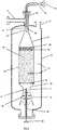
- the present invention provides an auto-thermal reforming unit (1) for alcohol reforming and hydrogen production suitable for a submarine, wherein the unit is an adiabatic fixed bed reactor arranged in a cylindrical envelope (27) surrounded by an outer shell (26) of metal alloy, the reactor comprising a catalytic bed (28), an alcohol and steam inlet (25), an oxygen inlet (36), a non return valve (37) arranged in the oxygen inlet (36), a divergent nozzle (32) with increasing size up to the diameter of the cylindrical envelope (27), wherein the auto-thermal reforming unit (1) comprises a Venturi type mixing element (33) and a distributor ring (41) which doses the oxygen in the Venturi type mixing element (33) or a lance (39) creating a Venturi throat (33).
- the unit is an adiabatic fixed bed reactor arranged in a cylindrical envelope (27) surrounded by an outer shell (26) of metal alloy, the reactor comprising a catalytic bed (28), an alcohol and steam inlet (25), an oxygen inlet (36), a non return
- a further embodiment is the auto-thermal reforming unit (1) of the second aspect, wherein the unit comprises a drilled distributor plate (31) and a ceramic material (40).
- a further embodiment is the auto-thermal reforming unit (1) of the second aspect, wherein the unit comprises a product outlet (34) and a mesh (35).
- a further embodiment is the auto-thermal reforming unit (1) of the second aspect, wherein the unit comprises palladium membranes.
- a further embodiment is the auto-thermal reforming unit (1) of the second aspect, wherein the unit comprises temperature sensors (30).
- a further embodiment is the auto-thermal reforming unit (1) of the second aspect, wherein the unit comprises a non-return valve (37) arranged in the oxygen inlet (36).
- the heat required to maintain optimum conditions for the reforming reaction is generated by the partial oxidation and combustion of the fuel.
- Ethanol steam reforming (as well as methanol) is a moderately endothermic, energy-absorbing reaction, where the products have higher energy than the reactants. This heat input must be constantly supplied since otherwise the reforming reaction would stop. The required heat is supplied in the reactor itself by the partial oxidation and combustion of the fuel. These reactions, unlike the previous one, are very exothermic, they release heat. Exothermic and endothermic reactions take place on the same equipment and on the same catalyst.
- the reverse reaction in the case of the methane steam reforming reaction, depending on the operating conditions and concentrations of components, the reverse reaction, called the methanation reaction, can take place. This reaction is undesired as it consumes hydrogen to generate methane.
- the ethanol decomposition could produce more methane through acetaldehyde decomposition or the acetaldehyde could be reformed with steam (reducing the methane production).
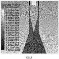
- the temperature in these first centimeters can reach 750°C/950°C (depending on the extent of partial oxidation or combustion reactions) in case of ethanol and 475°C/550°C in case of methanol.
- the outlet temperature of the bed however is approximately 550°C/750°C (depending on catalyst and main reaction extent) for ethanol and about 300°C for methanol.
- the outlet temperature is much lower since it has been time enough for the endothermic reforming reactions to take place, since they are slower, along the bed, and not only in the first centimeters. There is therefore a longitudinal temperature profile in an adiabatic type reactor, reaching the maximum value at the beginning and decreasing rapidly at first and slowly thereafter as the flow progresses along the catalytic bed. This is why a very specific reactor construction material is required to withstand these high temperature conditions together with high pressure.
- the present invention provides a boiler unit (3) for alcohol reforming and hydrogen production suitable for a submarine, wherein the unit is an adiabatic fixed bed reactor arranged in a cylindrical envelope (44) surrounded by an outer shell (43) of metal alloy, the reactor comprising a catalytic bed (50), a hydrogen and combustible gases inlet (42), an oxygen inlet (54), a first divergent nozzle (47) with increasing size up to the diameter of the cylindrical envelope (44), wherein the boiler unit (3) comprises a first Venturi type mixing element (51) and a distributor ring (49) which doses the oxygen in the first Venturi type mixing element (51) or a lance (63) which creates a Venturi throat (51), a second Venturi element (56), a second divergent nozzle (58), a water inlet (62) and a water injection lance (59).
- the boiler unit (3) comprises a first Venturi type mixing element (51) and a distributor ring (49) which doses the oxygen in the first Venturi type mixing element (51) or a lance (6
- a further embodiment is the boiler unit (3) of the third aspect, wherein the unit comprises a drilled distributor plate (46) and a ceramic material (40).
- a further embodiment is the boiler unit (3) of the third aspect, wherein the unit comprises a product outlet.
- a further embodiment is the boiler unit (3) of the third aspect, wherein the unit comprises deflector plates (60) arranged inside the second divergent nozzle (58).
- a further embodiment is the boiler unit (3) of the third aspect, wherein the unit comprises a non-return valve (53) arranged in the oxygen inlet (54).
- a further embodiment is the boiler unit (3) of the third aspect, wherein the unit comprises temperature sensors (45).
- the boiler unit (3) has two main functions:
- Palladium membranes are capable of separating hydrogen as long as there is some driving force.
- the driving force is proportional to the difference of the quadratic roots of the hydrogen partial pressure between on one side and the other of the membrane.
- the pressure of the permeate hydrogen at the outlet thereof should be approximately 2 barg to meet the acceptance requirements of the fuel cell. That is why there will always be a certain amount of hydrogen in the reject gas (the equivalent to 2 barg) that cannot be filtered through the membranes. This amount of hydrogen is the one that reaches the boiler.
- This oxygen content is measured at the outlet of the boiler unit (3) or at the exhaust gases outlet.
- the present invention provides a method for alcohol reforming and hydrogen production in a submarine, comprising an alcohol reforming and hydrogen production step in a system of the first aspect of the invention, wherein the pressure at the auto-thermal reforming unit (1) is from 30 to 40 barg and wherein the following steps are carried out in the auto-thermal reforming unit (1):
- a further embodiment is the method of the fourth aspect, wherein the following steps are carried out in the boiler unit (3):
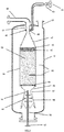
- Figure 1 depicts the method.
- a pump (4) impulses high-pressure alcohol from an alcohol inlet line (17) which is mixed with an amount of water (the ratio between the relative amounts of alcohol and water is controlled in every moment). This ratio varies with the fuel and the operating condition (starting or steady state).
- the water is supplied by a water pump (5) from a water separation vessel (6).
- the alcohol/water reactive mixture flows through a series of heat exchangers (7) and (8) to achieve the evaporation of the fluid.
- a certain controlled amount of oxygen is added to this alcohol and water mixture.
- Oxygen is taken from an oxygen inlet pipe (20).
- mixing is carried out in a mixing element located inside the auto-thermal reaction unit (1).
- the oxygen flow rate will vary and will be controlled as a function of the temperatures measured in the auto-thermal reforming unit (1).
- the heat is supplied by the exhaust gases from the boiler unit (3) and by the product gas from the outlet of the auto-thermal reforming unit (1), optimizing the energy efficiency of the system.
- an electric heater 10 is included.
- the electric heater (10) is used to heat an amount of CO 2 in the first moments of the starting sequence, taken from a CO 2 inlet pipe (18). Such warm CO 2 is circulated through the different equipment until enough temperature is reached to make active the different catalysts.
- Second type is an endothermic reaction, reforming the alcohol, whose reaction product, among others, is the desired hydrogen.
- the outlet gases of said unit (1) are first conducted to the heat exchanger (8) to supply part of its heat to the inlet alcohol/water mixture and subsequently to other heat exchanger (11) before entering the second stage of the process, the Water Gas Shift unit (2) and separation units with palladium membranes. This last heat exchange is carried out by cooling water. It is necessary to cool and control the temperature of these gases, since the membranes of palladium should not be operating with very high temperatures.
- the separation technology is based on palladium membranes, the use of which guarantees the production of very high purity hydrogen without traces of CO that could poison the catalyst of the fuel cell anode.
- the water gas shift reaction increases hydrogen production, eliminating a large part of the CO generated in the auto-thermal reforming unit (1). Pure hydrogen is produced to feed the fuel cell (out of the scope of this invention), conducted by a hydrogen outlet pipe (19).
- exhaust gases Prior to evacuating the exhaust gases from the boiler unit (3) at high pressure, exhaust gases pass through a heat exchanger (7) to transfer part of their energy to the initial mixture of alcohol and water reactants. This heat exchange allows improving the energy efficiency of the process.
- a further heat exchanger (14) cools enough the exhaust gases to condense all contained water and recover it in the water separator tank (6), thus separating it from the CO 2 .
- the condensed water will be reused in the process, being pumped to the different mixing points. It is necessary to introduce a small amount of water, controlled by level measurement in the vessel (6), to balance the water, so that the unit includes a high pressure water supply (15).
- the exhaust gases may be sent outside by an outlet pipe (16) to dissolve them with sea water by means of the exhaust gas dissolution unit.
- the method operates at a pressure up to 40 barg. For this reason, the method takes advantage of this pressure to directly evacuate the exhaust gases to the sea for dissolution. This means that it is not necessary to compress the exhaust gases when the boat is at diving depth, reducing the auto-consumption, size, weight, noise and vibration generation.
- the operating pressure is practically atmospheric, much less than the operating pressure of the present invention (about 40 barg).
- the rejection gases should be compressed from practically atmospheric pressure up to 30 or 40 barg (300 or 400 m depth, according to the submarine's operational diving depth). This high energy consumption makes this option unattractive in a submarine.
- the gases obtained from the reforming process are conditioned by a set of reactors arranged in series (WGS, COPROX, Methanation) which reduce the CO content to limits acceptable by the fuel cell. There is therefore a set of gas purification steps.
- the produced hydrogen is sent to the open anode Fuel Cell along with other compounds.
- the present invention comprises only one reactor and the product obtained from the reactor may be supplied to a separation process containing palladium membranes. From this separation step a pure hydrogen stream at low pressure is obtained which feeds directly to the closed anode fuel cell.
- EP2641866A1 an open anode configuration is operated by integrating the fuel cell into the process.
- a closed anode Fuel Cell is used.
- the stack is segregated from the process, which has many dynamic, control and safety advantages.
- the heat supplied to the reformer is obtained from the combustion of the anode rejection gases by heat exchange in microreactors.
- the reformer is an isothermal microchannel reactor.
- the heat required by the reforming process is supplied in the same reactor by an auto-reforming process. This implies that some of the alcohol supplied is burned to supply the heat required by the reforming reactions in the reactor itself. It is an adiabatic fixed bed reactor. In the present invention, no complex heat integration with reaction kinetics or very different reaction rates on both sides are required.
- EP2641866A1 discloses a system with a large number of stages, several heat exchangers, many reactors in series, a difficult heat integration system and a complex control.
- the present invention is based on a simpler auto-reforming process with three main steps and the control of the all integrated system is simpler.
- EP2641866A1 discloses a laboratory-sized system (photographs are shown) with microreactors and cartridges.
- the present invention refers to a system of higher processing capacity, suitable for the energy requirements of the submarine, which greatly simplifies the process with respect to the use of several of the equipments of EP2641866A1 working in parallel or scaling them.
- EP2641866A1 discloses a pre-reforming unit, which preferably produces methane, followed by a reforming unit to process said methane.
- a single auto-thermal reactor is carried out in a single step, trying to reduce direct methane formation and providing direct hydrogen production.
- EP2641866A1 The electrical consumption of EP2641866A1 is high, mainly because of the necessity of a CO 2 recirculation blower to control the temperature of the combustor. 15 kW are indicated in EP2641866A1 .
- the present invention has lower electrical consumption, about 3 kW, an important premise for a submarine.
- EP2525146 discloses a heat generation system (boiler) which replaces a prior flame combustion based system. The heat produced is supplied to the methanol reformer.
- the present invention contemplates a system and an alcohol reforming process for generating hydrogen. The purpose and goal are very different.
- hydrogen is produced in a first step and then burned in later steps.
- hydrogen is produced to be supplied to a fuel cell, not to be burned and to generate heat.
- EP2525146 a small amount of alcohol is processed to be burned and to provide heat to the main reforming process, which takes place in another equipment (methanol reformer).
- methanol reformer methanol reformer
- the processing flow is higher, since most of the required hydrogen is produced in a single reactor.
- EP2525146 discloses a process for methanol reforming, which takes place in a reactor, the heat required is generated by a boiler.
- the reforming reactor is of adiabatic type, in which the heat required by the reforming process is supplied directly in the same equipment by the partial oxidation of the alcohol in an auto-reforming process.
- the process of the present invention is simpler than that described in EP2525146 .
- EP2525146 discloses a process of catalytic combustion steps and dosages of oxygen arranged in series, where at least two steps must be arranged.
- the control to keep the system in a stable manner is complex, since disturbances produced in one step affect the later steps arranged in series, which can cause abrupt changes in temperature.
- This system is part of a methanol reformer process where a complex unit as the multi-stage boiler described shall be integrated.
- a complex unit as the multi-stage boiler described shall be integrated.
- the purpose of the boiler of the present invention is to burn the rejected gases of the membrane in a single step and to take advantage of the heat obtained to vaporize the alcohol/water reaction mixture.
- the present invention does not supply heat for the reforming process.
- US2007122667A1 the reactive mixture can combust with flame before reaching the catalyst of the auto-thermal reactor, a risky situation due to the high temperatures reached and the production of unwanted products.
- This scenario requires that the time the fuel-oxygen mixture is flowing before reaching the catalyst must be greater than the auto-ignition delay time.
- the auto-ignition delay time depends mainly on the temperature, the fuel nature, and to a lesser extent (but not less important) on the concentration of fuel and oxidizer and the pressure.
- US2007122667A1 the mixture of water and fuel is vaporized. This could imply elevated temperatures, depending on the operating pressure, which is not indicated on US2007122667A1 .
- the vaporized water/fuel is mixed with the oxygen, separated from the air, in a duct.
- US2007122667A1 does not disclose methods of starting or activating the catalysts.
- a temperature between 250 and 300 °C is required in order to start the auto-thermal catalytic process.
- a specific detailed method is proposed to solve this problem.
- US2007122667A1 discloses an optional method for eliminating sulfur contained in fuels such as diesel.
- the present invention utilizes sulfur-free fuel such as methanol or ethanol of a certain quality.
- US2007122667A1 discloses a water spray tempering step performed before WGS step. This is advantageous to favour the equilibrium of the WGS reaction but it makes difficult to separate the hydrogen because partial pressure is reduced in the subsequent purification step. It is more advisable and efficient to cool by heat exchange without water mixing prior to the WGS step, as done in the present invention.
- EP1808327A1 works at low pressure. This results in low pressurized exhaust gases. In advance, this condition is not a priori compatible with the requirements of a submarine. Rejection gases from the reforming process shall be removed and dissolved in seawater at any pressure, whatever the immersion level is. These rejection gases should be compressed from practically atmospheric pressure up to 30 or 40 barg (300 or 400 m depth, according to the submarine's operational diving depth). This high energy consumption makes this option unattractive in a submarine. EP1808327A1 appears to be designed for another type of vehicle.
- EP1808327A1 operates at low pressure and consequently the driving force for hydrogen separation is very low. Even with vacuum on the other side, the required membrane area will be very high, resulting in a more expensive and larger equipment due to the amount of Pd to be used.
- EP1808327A1 indicates temperatures of 700 ° C at the outlet of the reactor. This implies a peak of at least 850 °C which increases reactor wall thickness causing an excessive weight of the equipment, key aspect for a submarine.
- Another possible solution is to include refractory insulation inside the reactor, but this generates a large reactor size complicating the fulfilling of the requirements for submarine space.
- the system of EP1808327A1 does not solve this problem. In the present invention a detailed design method is proposed to solve this problem.
- the auto-thermal reactor of WO2011148066A2 operates with a high temperature peak in the first centimeters of catalytic bed as indicated above. This temperature peak can cause auto-ignition of the mixture before reaching the catalyst by radiation heat transfer.
- the document does not propose solutions to this problem. In the present invention a detailed design method is proposed to solve this problem.
- WO2011148066A2 As a result of the reforming of fuel, a certain amount of methane is obtained at the outlet of the reformer. Methane is a refractory compound to be catalytically burned. This implies high operating temperatures. In WO2011148066A2 , operating temperatures of 400 to 700 °C are indicated. These temperatures seem low to be able to burn the methane effectively. No tempering systems or methods suitable for controlling the temperature in the combustor are described in WO2011148066A2 . In the present invention a detailed design method is proposed to solve these problems.
- WO2011148066A2 does not describe any method of starting or activating the catalysts. No external heat source is identified to start and vaporize the water. In the case of ethanol, a temperature between 250 and 300 ° C is required in order to start the auto-thermal process. In the present invention a detailed design method is proposed to solve this problem.
- the system described in WO0125140A1 is complex, oriented to treat sulfur-containing fuels, such as diesel.
- the present invention uses Sulphur free fuel such as methanol or ethanol of a certain quality, therefore no method is contemplated to remove Sulphur.
- WO0125140A1 further includes in the process a scrubber with sea water, which gas outlet is fed back to the process with a compressor.
- This compression consumption results in significant energy inefficiency in a submarine.
- the present invention does not require this additional compressor.
- the problem that may occur is that the reactive mixture rises by swirling toward the top of the mixing chamber (62), outside of the tubes (24), since this space must be occupied by the gas. In this part of the chamber, if the temperature is sufficiently high, there is enough time to ignite the mixture, since it is a dead volume. Disposing dead volumes and designs that allow back-mixing in transients could cause a problem.
- the present invention does not allow the entering of fuel gas to the oxygen side, as this is introduced at a higher pressure.
- the venturi of the present invention causes the flows of both combustible gas and oxygen always to flow into the throat to be mixed, as it is a zone of lower pressure.
- Anti-return valves are also provided in the oxidant supply and the design does not include areas with dead volumes.
- US2004/0175665 does not describe methods to absorb radiated energy from the catalytic bed. This energy increases the temperature of the reactants, especially in the dead volumes, favouring the ignition and flame combustion in those zones.
- the present invention provides a distributor plate and inert filler material before reaching the catalyst. These materials absorb the radiation produced in the catalyst and avoids overheating the mixture before reaching the catalyst.
- US2004/0175665 discloses a complex system to be manufactured and operated because of the large number of distributor tubes.
- the present invention presents a simple system, easy to manufacture it.
- the oxidizer and fuel are introduced at 371 °C as minimum.
- the mixture must be correctly made since introducing hot oxygen implies that in areas where the oxygen concentration is very high (before it is completely mixed) the auto ignition delay time is very low (less of one second).
- the oxygen is introduced relatively cool (between 5°C and 10°C) and mixed with the fuel and water vapour at about 300°C, so the risk of auto-ignition until the mixture is homogeneous is minimum. This allows the auto-ignition delay time to be several seconds, so different loads can be considered instead of fixed 100% flow rate operation, without the risk of igniting the mixture upstream reaching the catalyst.
- inert material is included prior to reach the catalyst to prevent the propagation of the radiation from the catalytic zone.
- the present invention provides a perforated distributor plate, avoiding radiation transmission more effectively, since it creates an additional flat surface which collects almost all the remaining radiation.
- the arrangement disclosed in US3871838 may cause part of the fuel to enter the oxidizing gas distributor and accumulates in the dead zone of longitudinal extension, especially in transients. As a result, auto-ignition and flame combustion can take place in this dead zone.
- the present invention does not allow fuel gas to enter into the oxygen side, as this is introduced at a higher pressure.
- the Venturi of the present invention drives the flow rate of both combustible gas and oxygen into the throat to be mixed, as it is a zone of lower pressure.
- Non return valves are also included in the oxidant supply and dead zones are not included in the design.
- the oxidant is also introduced at a relatively low temperature with the advantages indicated above.
- US3871838 also has an additional air inlet and a spark generator to ignite the initial mixture and maintain a controlled combustion at the start up, heating the catalyst to working conditions. Spark ignition methods are very complex to control at high pressures and flames reduce their size under pressure. US3871838 does not mention operating pressure, but a flame ignition and control system for this initial heating presents many problems at an operating pressure of about 40 barg, as is the case of the present invention.
- US3871838 proposes a complex system to manufacture and operate because of the large number of dispensing tubes.
- the present invention represents a simple system, easy to manufacture it.
- US4865820 The operating pressure in US4865820 is lower than the one considered in the present invention (about 27 barg versus 40 barg). This involves using a rejection gas compressor to pump the fluid to the diving depth, producing a moderate energy consumption. The present invention does not require this compressor, improving energy efficiency, an important aspect in a submarine.
- US4865820 uses a single down flow pass through the reactor.
- an inner refractory material is coating the reactor to avoid high temperatures in the metal.
- a downward flow through an inner tube and subsequent upward flow in an outer ring is foreseen as described above.
- Lower temperatures in the enclosure mean that it is not necessary to use interior refractory material. This is a significant advantage in the occupied volume as indicated in the analysis of the others patents.
- the operating pressure is lower than the used in the present invention (about 21 barg versus 40 barg), requiring a compressor to be able to evacuate the exhaust gases in a submarine, consuming a precious energy.
- the exterior being designed to withstand the pressure and moderate-low temperature and the interior for low differential pressure and high temperature has the same purpose both in WO2011148068A2 and in the present invention, which is to reduce the thickness and consequently the weight of the outer casing.
- the two enclosures are communicated, first the fluid crosses the inner shell and then the exterior one, with a U-shaped flow pattern.
- the pressure difference which has to withstand the inner shell, which sees high temperature, is just the pressure drop of the fluid between the two enclosures.
- the space between the two shells is occupied by an inert gas.
- a very accurate and fast pressure control of the space between envelopes is required to match it as close as possible to the pressure inside the reactor.
- the pressure control of the inert gas in the space between enclosures could not act quick enough, and important pressure differences, both positive and negative, could be created.
- These pressure differences have a very negative impact on the mechanical strength of the inner shell which is further subjected to high temperatures. There is a risk of breaking the inner shell. In the present invention, this situation cannot occur because both envelopes are physically communicated.
- the outer shell in WO2011148068A2 does not contain a catalyst and is occupied by an inert gas.
- a larger size than in the present invention is expected since it is a non catalytic space.
- This space acts as insulation.
- the space is better utilized by communicating the two envelopes and by passing reactive fluid in contact with the catalyst through the outer envelope.
- the reactor is cooled, with refrigeration water, by tubes arranged outside the reaction envelope. This causes a marked radial temperature profile. This is not an adiabatic reactor. In addition, having catalyst in the form of monoliths makes the radial mixing even more difficult and the radial temperature profile is more pronounced.
- the reactor of the present invention is fully adiabatic, eliminating accentuated radial temperature gradients. These lower temperatures at the sides favour not complete conversion of the fuel and methanation (methane generation, reducing the selectivity towards hydrogen).
- WO2011148068A2 there may be retro-mixing of the gases in the different zones according to this provision in transients.
- the chamber where oxygen is introduced to the venturi elements has large dead volumes in which the water-hydrocarbon mixture can enter and be trapped.
- oxygen is being introduced at 250 ° C to 300 ° C (regarding the 5-15 ° C of the present invention), drastically shortening the auto-ignition delay time.
- WO2011148068A2 discloses a chamber for mixing and atomizing the fuel.
- the fuel and steam are already mixed and vaporized, therefore this part of the design is simpler.
- WO2011148068A2 a multitude of venturi type mixing elements for fuel and oxidizer (between 300 and 2000 per square meter) are included. This design minimizes contact time regarding a single venturi, as is the case of the present invention.
- the design of WO2011148068A2 is thought to have very small auto-ignition delay times, mainly due to operating at higher pressures, higher temperatures and especially to operate with diesel (the diesel fuel has a low auto-ignition delay time, associated with a high cetane number, however, ethanol has a lower cetane number or a much higher auto-ignition delay time, much more gasoline-like).
- the type of fuel, the lower operating pressures and the lower operating temperatures make the auto-ignition delay time much higher in the present invention, being able to use a single Venturi system, which greatly simplifies the design and facilitates the manufacturing.
- Operating pressure in WO2015198186A1 is lower than the one of the present invention (about 4 barg versus 40 barg). It is indicated that water is vaporized at 150 °C and this implies a maximum pressure of 4 barg.
- the application is probably a land industrial type, not oriented to the submarine industry, since the described design requires using a rejection gas compressor to bring the fluid to the diving depth, requiring a moderate energy consumption.
- the present invention does not require this compressor, improving energy efficiency, an important aspect in a submarine.
- the inlet temperature of the gases is also higher (about 450 ° C, with the unit started, against 300 ° C in the present invention). At these temperatures (both fuel and oxidizer are introduced at this temperature) the auto-ignition delay time is lower.
- a combustion and fuel mixer as indicated in WO2015198186A1 should not be of the static mixer type, which, while providing well mixing, generates too many vortices and increases residence time of the fluid, before reaching the catalyst, against the auto-ignition delay time.
- WO2015198186A1 uses a single downward gas flow pattern along the reactor.
- inner refractory materials to avoid high temperatures in the metal wall coat the reactor.
- a downward flow through an inner tube and further upward flow through an outer ring is utilized, as described above.
- Lower temperatures in the outer enclosure mean that it is not necessary to use inner refractory material. This is a significant advantage in the volume occupied as indicated in the analysis of above patents.
- US2008011250A1 discloses a first chamber for mixing, atomizing and vaporizing the liquid fuel with steam.
- the present invention does not have such a chamber, since the fuel and steam are already vaporized and pre-mixed. It results in a simpler design of the reforming reactor than US2008011250A1 .
- the temperature of the vapour mixture from the first chamber is about 400 °C, greater than 300 °C of the present invention. This assumes that the mixing process with the oxidizing agent is more critical in order to avoid possible auto-ignition.
- the oxidant dosing chamber has significant dead volumes. This arrangement may cause part of the fuel to enter the oxidizing gas distributor, especially in transient operations, and to accumulate in the dead space zone of longitudinal extension. It is therefore possible for auto-ignition and flame combustion to occur in the distributor.
- the present invention solves these problems.
- the auto-thermal reforming unit (1) described in Figure 3 comprises the elements described in the auto-thermal reforming unit (1) described in Figure 2 , with the exception of the following modifications:
- the auto-thermal reforming unit (1) described in Figure 4 comprises the elements described in the auto-thermal reforming unit (1) described in Figure 2 , with the exception of the following modifications:
- the boiler unit (3) described in Figure 6 comprises the elements described in the boiler unit (3) described in Figure 5 , with the exception of the following modifications:
- the boiler unit (3) described in Figure 7 comprises the elements described in the boiler unit (3) described in Figure 5 , with the exception of the following modifications:
- the temperature probes (45) used to measure the inner temperature inside the envelope (44) are replaced by a thermowell arranged in vertical position. It allows the use of multi-point temperature sensors distributed along the thermowell, allowing a more easy to construct embodiment.
Priority Applications (2)
| Application Number | Priority Date | Filing Date | Title |
|---|---|---|---|
| EP17382564.7A EP3441360B1 (de) | 2017-08-10 | 2017-08-10 | System zum umformen von alkohol und zur wasserstoffherstellung, einheiten des systems und verfahren dafür |
| ES17382564T ES2828799T3 (es) | 2017-08-10 | 2017-08-10 | Sistema de reformado de alcohol y producción de hidrógeno, unidades del sistema y su método asociado |
Applications Claiming Priority (1)
| Application Number | Priority Date | Filing Date | Title |
|---|---|---|---|
| EP17382564.7A EP3441360B1 (de) | 2017-08-10 | 2017-08-10 | System zum umformen von alkohol und zur wasserstoffherstellung, einheiten des systems und verfahren dafür |
Publications (2)
| Publication Number | Publication Date |
|---|---|
| EP3441360A1 true EP3441360A1 (de) | 2019-02-13 |
| EP3441360B1 EP3441360B1 (de) | 2020-07-29 |
Family
ID=59699639
Family Applications (1)
| Application Number | Title | Priority Date | Filing Date |
|---|---|---|---|
| EP17382564.7A Active EP3441360B1 (de) | 2017-08-10 | 2017-08-10 | System zum umformen von alkohol und zur wasserstoffherstellung, einheiten des systems und verfahren dafür |
Country Status (2)
| Country | Link |
|---|---|
| EP (1) | EP3441360B1 (de) |
| ES (1) | ES2828799T3 (de) |
Cited By (1)
| Publication number | Priority date | Publication date | Assignee | Title |
|---|---|---|---|---|
| EP3693338A1 (de) * | 2019-02-07 | 2020-08-12 | Sener Ingenieria Y Sistemas, S.A. | Autothermisches hochdrucksystem zur reformierung von alkohol und zur herstellung von wasserstoff, verfahren und einheiten dafür |
Citations (19)
| Publication number | Priority date | Publication date | Assignee | Title |
|---|---|---|---|---|
| US3871838A (en) | 1972-07-03 | 1975-03-18 | Siemens Ag | Apparatus for reacting vaporized, gasified or atomized hydrocarbon with a gas serving as an oxygen carrier |
| US4865820A (en) | 1987-08-14 | 1989-09-12 | Davy Mckee Corporation | Gas mixer and distributor for reactor |
| WO2001025140A1 (en) | 1999-10-05 | 2001-04-12 | Ballard Power Systems Inc. | Fuel cell power generation system with autothermal reformer |
| US20020088179A1 (en) | 2000-01-24 | 2002-07-11 | Lesieur Roger R. | Autothermal fuel gas reformer assemblage |
| US6620389B1 (en) | 2000-06-21 | 2003-09-16 | Utc Fuel Cells, Llc | Fuel gas reformer assemblage |
| US20040175665A1 (en) | 2001-03-30 | 2004-09-09 | Goebel Steven G. | Apparatus for mixing fuel and an oxidant |
| US20050066577A1 (en) | 2003-08-22 | 2005-03-31 | Syntroleum Corporation | Process for production of synthesis gas using an oxygen-containing gas |
| WO2006065766A2 (en) | 2004-12-14 | 2006-06-22 | Syntroleum Corporation | Burnerless autothermal reformer mixer |
| US20070122667A1 (en) | 2005-11-28 | 2007-05-31 | Kelley Richard H | Fuel cell system with integrated fuel processor |
| EP1808327A1 (de) | 2006-01-13 | 2007-07-18 | Claudio Rossi | Produktion elektrischer Energie durch Brennstoffzellen mit Wasserstoff aus der katalytischen Reformierung von Ethanol |
| US20080011250A1 (en) | 2004-11-17 | 2008-01-17 | Zdenek Pors | Mixing Chamber for a Reformer and Method for Operating Same |
| US20080141675A1 (en) * | 2006-12-14 | 2008-06-19 | Texaco Inc. | Hybrid Combustor for Fuel Processing Applications |
| EP1995212A1 (de) * | 2006-03-14 | 2008-11-26 | Mitsubishi Gas Chemical Company, Inc. | Wasserstoffgenerator und verfahren zur erzeugung von wasserstoff |
| WO2011148066A2 (fr) | 2010-05-25 | 2011-12-01 | IFP Energies Nouvelles | Procédé de production anaérobie d'hydrogène |
| WO2011148068A2 (fr) | 2010-05-25 | 2011-12-01 | IFP Energies Nouvelles | Réacteur pour le reformage autotherme de gasoil |
| EP2525146A2 (de) | 2011-05-14 | 2012-11-21 | Howaldtswerke-Deutsche Werft GmbH | Verfahren zur Verbrennung eines Brennstoff-Sauerstoff-Gemisches und Vorrichtung zur Durchführung dieses Verfahrens |
| EP2641866A1 (de) | 2010-11-18 | 2013-09-25 | Técnicas Reunidas, S.A. | In luftunabhängige antriebssysteme integriertes ethanolverarbeitungssystem |
| WO2015018962A2 (es) * | 2013-08-07 | 2015-02-12 | Abengoa Hidrogeno, S. A. | Quemador integrado en un sistema de reformado de hidrocarburos y alcoholes y sistema de reformado de hidrocarburos y alcoholes que lo comprende y procedimiento asociado |
| WO2015198186A1 (en) | 2014-06-23 | 2015-12-30 | Tubitak | An autothermal reformer reactor and a feeding system thereof |
-
2017
- 2017-08-10 ES ES17382564T patent/ES2828799T3/es active Active
- 2017-08-10 EP EP17382564.7A patent/EP3441360B1/de active Active
Patent Citations (19)
| Publication number | Priority date | Publication date | Assignee | Title |
|---|---|---|---|---|
| US3871838A (en) | 1972-07-03 | 1975-03-18 | Siemens Ag | Apparatus for reacting vaporized, gasified or atomized hydrocarbon with a gas serving as an oxygen carrier |
| US4865820A (en) | 1987-08-14 | 1989-09-12 | Davy Mckee Corporation | Gas mixer and distributor for reactor |
| WO2001025140A1 (en) | 1999-10-05 | 2001-04-12 | Ballard Power Systems Inc. | Fuel cell power generation system with autothermal reformer |
| US20020088179A1 (en) | 2000-01-24 | 2002-07-11 | Lesieur Roger R. | Autothermal fuel gas reformer assemblage |
| US6620389B1 (en) | 2000-06-21 | 2003-09-16 | Utc Fuel Cells, Llc | Fuel gas reformer assemblage |
| US20040175665A1 (en) | 2001-03-30 | 2004-09-09 | Goebel Steven G. | Apparatus for mixing fuel and an oxidant |
| US20050066577A1 (en) | 2003-08-22 | 2005-03-31 | Syntroleum Corporation | Process for production of synthesis gas using an oxygen-containing gas |
| US20080011250A1 (en) | 2004-11-17 | 2008-01-17 | Zdenek Pors | Mixing Chamber for a Reformer and Method for Operating Same |
| WO2006065766A2 (en) | 2004-12-14 | 2006-06-22 | Syntroleum Corporation | Burnerless autothermal reformer mixer |
| US20070122667A1 (en) | 2005-11-28 | 2007-05-31 | Kelley Richard H | Fuel cell system with integrated fuel processor |
| EP1808327A1 (de) | 2006-01-13 | 2007-07-18 | Claudio Rossi | Produktion elektrischer Energie durch Brennstoffzellen mit Wasserstoff aus der katalytischen Reformierung von Ethanol |
| EP1995212A1 (de) * | 2006-03-14 | 2008-11-26 | Mitsubishi Gas Chemical Company, Inc. | Wasserstoffgenerator und verfahren zur erzeugung von wasserstoff |
| US20080141675A1 (en) * | 2006-12-14 | 2008-06-19 | Texaco Inc. | Hybrid Combustor for Fuel Processing Applications |
| WO2011148066A2 (fr) | 2010-05-25 | 2011-12-01 | IFP Energies Nouvelles | Procédé de production anaérobie d'hydrogène |
| WO2011148068A2 (fr) | 2010-05-25 | 2011-12-01 | IFP Energies Nouvelles | Réacteur pour le reformage autotherme de gasoil |
| EP2641866A1 (de) | 2010-11-18 | 2013-09-25 | Técnicas Reunidas, S.A. | In luftunabhängige antriebssysteme integriertes ethanolverarbeitungssystem |
| EP2525146A2 (de) | 2011-05-14 | 2012-11-21 | Howaldtswerke-Deutsche Werft GmbH | Verfahren zur Verbrennung eines Brennstoff-Sauerstoff-Gemisches und Vorrichtung zur Durchführung dieses Verfahrens |
| WO2015018962A2 (es) * | 2013-08-07 | 2015-02-12 | Abengoa Hidrogeno, S. A. | Quemador integrado en un sistema de reformado de hidrocarburos y alcoholes y sistema de reformado de hidrocarburos y alcoholes que lo comprende y procedimiento asociado |
| WO2015198186A1 (en) | 2014-06-23 | 2015-12-30 | Tubitak | An autothermal reformer reactor and a feeding system thereof |
Cited By (2)
| Publication number | Priority date | Publication date | Assignee | Title |
|---|---|---|---|---|
| EP3693338A1 (de) * | 2019-02-07 | 2020-08-12 | Sener Ingenieria Y Sistemas, S.A. | Autothermisches hochdrucksystem zur reformierung von alkohol und zur herstellung von wasserstoff, verfahren und einheiten dafür |
| WO2020160935A1 (en) * | 2019-02-07 | 2020-08-13 | Sener, Ingeniería Y Sistemas, S.A. | High-pressure auto-thermal system for reforming alcohol and producing hydrogen, method and units thereof |
Also Published As
| Publication number | Publication date |
|---|---|
| EP3441360B1 (de) | 2020-07-29 |
| ES2828799T3 (es) | 2021-05-27 |
Similar Documents
| Publication | Publication Date | Title |
|---|---|---|
| US7832364B2 (en) | Heat transfer unit for steam generation and gas preheating | |
| US7931709B2 (en) | Process and apparatus for generating hydrogen | |
| US20080019902A1 (en) | Process for producing hydrogen | |
| US7578669B2 (en) | Hybrid combustor for fuel processing applications | |
| RU2415073C2 (ru) | Компактный реактор реформинга | |
| US8986405B2 (en) | Gas generator and processes for the conversion of a fuel into an oxygen-depleted gas and/or hydrogen-enriched gas | |
| US20090293358A1 (en) | Catalytic system for converting liquid fuels into syngas | |
| WO2008057335A2 (en) | Catalytic system for converting liquid fuels into syngas | |
| US20080141584A1 (en) | Methods for Using a Catalyst Preburner in Fuel Processing Applications | |
| US20030188475A1 (en) | Dynamic fuel processor with controlled declining temperatures | |
| US20050188615A1 (en) | Integrated fuel processor subsystem with quasi-autothermal reforming | |
| EP2641866B1 (de) | In luftunabhängige antriebssysteme integriertes ethanolverarbeitungssystem | |
| EP3693338B1 (de) | Autothermisches hochdrucksystem zur reformierung von alkohol und zur herstellung von wasserstoff, und verfahre dafür | |
| EP3441360B1 (de) | System zum umformen von alkohol und zur wasserstoffherstellung, einheiten des systems und verfahren dafür | |
| EP3722257A1 (de) | Vorrichtung und verfahren zur herstellung von wasserstoffhaltigem gas | |
| JP2008214165A (ja) | 可燃ガス混合方法及び混合器 | |
| US20020088179A1 (en) | Autothermal fuel gas reformer assemblage | |
| KR20160045737A (ko) | 탄화수소 및 알코올 개질 시스템 용 버너, 상기 버너를 포함하는 탄화수소 및 알코올 개질 시스템 및 관련 방법 | |
| US8690976B2 (en) | Fuel reformer | |
| JP3051564B2 (ja) | 水蒸気改質反応器 | |
| US20120014864A1 (en) | Hybrid foam/low-pressure autothermal reformer | |
| AU2013206509A1 (en) | Heat transfer unit for steam generation and gas preheating |
Legal Events
| Date | Code | Title | Description |
|---|---|---|---|
| PUAI | Public reference made under article 153(3) epc to a published international application that has entered the european phase |
Free format text: ORIGINAL CODE: 0009012 |
|
| STAA | Information on the status of an ep patent application or granted ep patent |
Free format text: STATUS: THE APPLICATION HAS BEEN PUBLISHED |
|
| AK | Designated contracting states |
Kind code of ref document: A1 Designated state(s): AL AT BE BG CH CY CZ DE DK EE ES FI FR GB GR HR HU IE IS IT LI LT LU LV MC MK MT NL NO PL PT RO RS SE SI SK SM TR |
|
| AX | Request for extension of the european patent |
Extension state: BA ME |
|
| STAA | Information on the status of an ep patent application or granted ep patent |
Free format text: STATUS: REQUEST FOR EXAMINATION WAS MADE |
|
| 17P | Request for examination filed |
Effective date: 20190805 |
|
| RBV | Designated contracting states (corrected) |
Designated state(s): AL AT BE BG CH CY CZ DE DK EE ES FI FR GB GR HR HU IE IS IT LI LT LU LV MC MK MT NL NO PL PT RO RS SE SI SK SM TR |
|
| GRAP | Despatch of communication of intention to grant a patent |
Free format text: ORIGINAL CODE: EPIDOSNIGR1 |
|
| STAA | Information on the status of an ep patent application or granted ep patent |
Free format text: STATUS: GRANT OF PATENT IS INTENDED |
|
| RIC1 | Information provided on ipc code assigned before grant |
Ipc: C01B 3/50 20060101ALI20200505BHEP Ipc: C01B 3/32 20060101AFI20200505BHEP |
|
| INTG | Intention to grant announced |
Effective date: 20200526 |
|
| GRAS | Grant fee paid |
Free format text: ORIGINAL CODE: EPIDOSNIGR3 |
|
| GRAA | (expected) grant |
Free format text: ORIGINAL CODE: 0009210 |
|
| STAA | Information on the status of an ep patent application or granted ep patent |
Free format text: STATUS: THE PATENT HAS BEEN GRANTED |
|
| AK | Designated contracting states |
Kind code of ref document: B1 Designated state(s): AL AT BE BG CH CY CZ DE DK EE ES FI FR GB GR HR HU IE IS IT LI LT LU LV MC MK MT NL NO PL PT RO RS SE SI SK SM TR |
|
| REG | Reference to a national code |
Ref country code: CH Ref legal event code: EP |
|
| REG | Reference to a national code |
Ref country code: DE Ref legal event code: R096 Ref document number: 602017020511 Country of ref document: DE |
|
| REG | Reference to a national code |
Ref country code: AT Ref legal event code: REF Ref document number: 1295567 Country of ref document: AT Kind code of ref document: T Effective date: 20200815 |
|
| REG | Reference to a national code |
Ref country code: IE Ref legal event code: FG4D |
|
| REG | Reference to a national code |
Ref country code: LT Ref legal event code: MG4D |
|
| REG | Reference to a national code |
Ref country code: NL Ref legal event code: MP Effective date: 20200729 |
|
| REG | Reference to a national code |
Ref country code: AT Ref legal event code: MK05 Ref document number: 1295567 Country of ref document: AT Kind code of ref document: T Effective date: 20200729 |
|
| PG25 | Lapsed in a contracting state [announced via postgrant information from national office to epo] |
Ref country code: LT Free format text: LAPSE BECAUSE OF FAILURE TO SUBMIT A TRANSLATION OF THE DESCRIPTION OR TO PAY THE FEE WITHIN THE PRESCRIBED TIME-LIMIT Effective date: 20200729 Ref country code: HR Free format text: LAPSE BECAUSE OF FAILURE TO SUBMIT A TRANSLATION OF THE DESCRIPTION OR TO PAY THE FEE WITHIN THE PRESCRIBED TIME-LIMIT Effective date: 20200729 Ref country code: BG Free format text: LAPSE BECAUSE OF FAILURE TO SUBMIT A TRANSLATION OF THE DESCRIPTION OR TO PAY THE FEE WITHIN THE PRESCRIBED TIME-LIMIT Effective date: 20201029 Ref country code: SE Free format text: LAPSE BECAUSE OF FAILURE TO SUBMIT A TRANSLATION OF THE DESCRIPTION OR TO PAY THE FEE WITHIN THE PRESCRIBED TIME-LIMIT Effective date: 20200729 Ref country code: GR Free format text: LAPSE BECAUSE OF FAILURE TO SUBMIT A TRANSLATION OF THE DESCRIPTION OR TO PAY THE FEE WITHIN THE PRESCRIBED TIME-LIMIT Effective date: 20201030 Ref country code: PT Free format text: LAPSE BECAUSE OF FAILURE TO SUBMIT A TRANSLATION OF THE DESCRIPTION OR TO PAY THE FEE WITHIN THE PRESCRIBED TIME-LIMIT Effective date: 20201130 Ref country code: NO Free format text: LAPSE BECAUSE OF FAILURE TO SUBMIT A TRANSLATION OF THE DESCRIPTION OR TO PAY THE FEE WITHIN THE PRESCRIBED TIME-LIMIT Effective date: 20201029 Ref country code: FI Free format text: LAPSE BECAUSE OF FAILURE TO SUBMIT A TRANSLATION OF THE DESCRIPTION OR TO PAY THE FEE WITHIN THE PRESCRIBED TIME-LIMIT Effective date: 20200729 Ref country code: AT Free format text: LAPSE BECAUSE OF FAILURE TO SUBMIT A TRANSLATION OF THE DESCRIPTION OR TO PAY THE FEE WITHIN THE PRESCRIBED TIME-LIMIT Effective date: 20200729 |
|
| PG25 | Lapsed in a contracting state [announced via postgrant information from national office to epo] |
Ref country code: RS Free format text: LAPSE BECAUSE OF FAILURE TO SUBMIT A TRANSLATION OF THE DESCRIPTION OR TO PAY THE FEE WITHIN THE PRESCRIBED TIME-LIMIT Effective date: 20200729 Ref country code: LV Free format text: LAPSE BECAUSE OF FAILURE TO SUBMIT A TRANSLATION OF THE DESCRIPTION OR TO PAY THE FEE WITHIN THE PRESCRIBED TIME-LIMIT Effective date: 20200729 Ref country code: PL Free format text: LAPSE BECAUSE OF FAILURE TO SUBMIT A TRANSLATION OF THE DESCRIPTION OR TO PAY THE FEE WITHIN THE PRESCRIBED TIME-LIMIT Effective date: 20200729 Ref country code: IS Free format text: LAPSE BECAUSE OF FAILURE TO SUBMIT A TRANSLATION OF THE DESCRIPTION OR TO PAY THE FEE WITHIN THE PRESCRIBED TIME-LIMIT Effective date: 20201129 |
|
| REG | Reference to a national code |
Ref country code: DE Ref legal event code: R119 Ref document number: 602017020511 Country of ref document: DE |
|
| PG25 | Lapsed in a contracting state [announced via postgrant information from national office to epo] |
Ref country code: NL Free format text: LAPSE BECAUSE OF FAILURE TO SUBMIT A TRANSLATION OF THE DESCRIPTION OR TO PAY THE FEE WITHIN THE PRESCRIBED TIME-LIMIT Effective date: 20200729 |
|
| REG | Reference to a national code |
Ref country code: CH Ref legal event code: PL |
|
| PG25 | Lapsed in a contracting state [announced via postgrant information from national office to epo] |
Ref country code: DK Free format text: LAPSE BECAUSE OF FAILURE TO SUBMIT A TRANSLATION OF THE DESCRIPTION OR TO PAY THE FEE WITHIN THE PRESCRIBED TIME-LIMIT Effective date: 20200729 Ref country code: CZ Free format text: LAPSE BECAUSE OF FAILURE TO SUBMIT A TRANSLATION OF THE DESCRIPTION OR TO PAY THE FEE WITHIN THE PRESCRIBED TIME-LIMIT Effective date: 20200729 Ref country code: CH Free format text: LAPSE BECAUSE OF NON-PAYMENT OF DUE FEES Effective date: 20200831 Ref country code: RO Free format text: LAPSE BECAUSE OF FAILURE TO SUBMIT A TRANSLATION OF THE DESCRIPTION OR TO PAY THE FEE WITHIN THE PRESCRIBED TIME-LIMIT Effective date: 20200729 Ref country code: LI Free format text: LAPSE BECAUSE OF NON-PAYMENT OF DUE FEES Effective date: 20200831 Ref country code: LU Free format text: LAPSE BECAUSE OF NON-PAYMENT OF DUE FEES Effective date: 20200810 Ref country code: EE Free format text: LAPSE BECAUSE OF FAILURE TO SUBMIT A TRANSLATION OF THE DESCRIPTION OR TO PAY THE FEE WITHIN THE PRESCRIBED TIME-LIMIT Effective date: 20200729 Ref country code: IT Free format text: LAPSE BECAUSE OF FAILURE TO SUBMIT A TRANSLATION OF THE DESCRIPTION OR TO PAY THE FEE WITHIN THE PRESCRIBED TIME-LIMIT Effective date: 20200729 Ref country code: SM Free format text: LAPSE BECAUSE OF FAILURE TO SUBMIT A TRANSLATION OF THE DESCRIPTION OR TO PAY THE FEE WITHIN THE PRESCRIBED TIME-LIMIT Effective date: 20200729 |
|
| REG | Reference to a national code |
Ref country code: BE Ref legal event code: MM Effective date: 20200831 |
|
| REG | Reference to a national code |
Ref country code: ES Ref legal event code: FG2A Ref document number: 2828799 Country of ref document: ES Kind code of ref document: T3 Effective date: 20210527 |
|
| PG25 | Lapsed in a contracting state [announced via postgrant information from national office to epo] |
Ref country code: AL Free format text: LAPSE BECAUSE OF FAILURE TO SUBMIT A TRANSLATION OF THE DESCRIPTION OR TO PAY THE FEE WITHIN THE PRESCRIBED TIME-LIMIT Effective date: 20200729 |
|
| PLBE | No opposition filed within time limit |
Free format text: ORIGINAL CODE: 0009261 |
|
| STAA | Information on the status of an ep patent application or granted ep patent |
Free format text: STATUS: NO OPPOSITION FILED WITHIN TIME LIMIT |
|
| PG25 | Lapsed in a contracting state [announced via postgrant information from national office to epo] |
Ref country code: SK Free format text: LAPSE BECAUSE OF FAILURE TO SUBMIT A TRANSLATION OF THE DESCRIPTION OR TO PAY THE FEE WITHIN THE PRESCRIBED TIME-LIMIT Effective date: 20200729 |
|
| 26N | No opposition filed |
Effective date: 20210430 |
|
| PG25 | Lapsed in a contracting state [announced via postgrant information from national office to epo] |
Ref country code: FR Free format text: LAPSE BECAUSE OF NON-PAYMENT OF DUE FEES Effective date: 20200929 Ref country code: DE Free format text: LAPSE BECAUSE OF NON-PAYMENT OF DUE FEES Effective date: 20210302 |
|
| PG25 | Lapsed in a contracting state [announced via postgrant information from national office to epo] |
Ref country code: SI Free format text: LAPSE BECAUSE OF FAILURE TO SUBMIT A TRANSLATION OF THE DESCRIPTION OR TO PAY THE FEE WITHIN THE PRESCRIBED TIME-LIMIT Effective date: 20200729 Ref country code: IE Free format text: LAPSE BECAUSE OF NON-PAYMENT OF DUE FEES Effective date: 20200810 Ref country code: BE Free format text: LAPSE BECAUSE OF NON-PAYMENT OF DUE FEES Effective date: 20200831 |
|
| GBPC | Gb: european patent ceased through non-payment of renewal fee |
Effective date: 20210810 |
|
| PG25 | Lapsed in a contracting state [announced via postgrant information from national office to epo] |
Ref country code: TR Free format text: LAPSE BECAUSE OF FAILURE TO SUBMIT A TRANSLATION OF THE DESCRIPTION OR TO PAY THE FEE WITHIN THE PRESCRIBED TIME-LIMIT Effective date: 20200729 Ref country code: MT Free format text: LAPSE BECAUSE OF FAILURE TO SUBMIT A TRANSLATION OF THE DESCRIPTION OR TO PAY THE FEE WITHIN THE PRESCRIBED TIME-LIMIT Effective date: 20200729 Ref country code: CY Free format text: LAPSE BECAUSE OF FAILURE TO SUBMIT A TRANSLATION OF THE DESCRIPTION OR TO PAY THE FEE WITHIN THE PRESCRIBED TIME-LIMIT Effective date: 20200729 |
|
| PG25 | Lapsed in a contracting state [announced via postgrant information from national office to epo] |
Ref country code: MK Free format text: LAPSE BECAUSE OF FAILURE TO SUBMIT A TRANSLATION OF THE DESCRIPTION OR TO PAY THE FEE WITHIN THE PRESCRIBED TIME-LIMIT Effective date: 20200729 Ref country code: MC Free format text: LAPSE BECAUSE OF FAILURE TO SUBMIT A TRANSLATION OF THE DESCRIPTION OR TO PAY THE FEE WITHIN THE PRESCRIBED TIME-LIMIT Effective date: 20200729 |
|
| PG25 | Lapsed in a contracting state [announced via postgrant information from national office to epo] |
Ref country code: GB Free format text: LAPSE BECAUSE OF NON-PAYMENT OF DUE FEES Effective date: 20210810 |
|
| PGFP | Annual fee paid to national office [announced via postgrant information from national office to epo] |
Ref country code: ES Payment date: 20230905 Year of fee payment: 7 |