EP3441267B1 - Système d'accès pour un véhicule - Google Patents
Système d'accès pour un véhicule Download PDFInfo
- Publication number
- EP3441267B1 EP3441267B1 EP17465536.5A EP17465536A EP3441267B1 EP 3441267 B1 EP3441267 B1 EP 3441267B1 EP 17465536 A EP17465536 A EP 17465536A EP 3441267 B1 EP3441267 B1 EP 3441267B1
- Authority
- EP
- European Patent Office
- Prior art keywords
- vehicle
- access arrangement
- electrical energy
- arrangement according
- storage device
- Prior art date
- Legal status (The legal status is an assumption and is not a legal conclusion. Google has not performed a legal analysis and makes no representation as to the accuracy of the status listed.)
- Active
Links
Images
Classifications
-
- B—PERFORMING OPERATIONS; TRANSPORTING
- B60—VEHICLES IN GENERAL
- B60R—VEHICLES, VEHICLE FITTINGS, OR VEHICLE PARTS, NOT OTHERWISE PROVIDED FOR
- B60R25/00—Fittings or systems for preventing or indicating unauthorised use or theft of vehicles
- B60R25/40—Features of the power supply for the anti-theft system, e.g. anti-theft batteries, back-up power supply or means to save battery power
- B60R25/403—Power supply in the vehicle
-
- B—PERFORMING OPERATIONS; TRANSPORTING
- B60—VEHICLES IN GENERAL
- B60R—VEHICLES, VEHICLE FITTINGS, OR VEHICLE PARTS, NOT OTHERWISE PROVIDED FOR
- B60R25/00—Fittings or systems for preventing or indicating unauthorised use or theft of vehicles
- B60R25/20—Means to switch the anti-theft system on or off
- B60R25/24—Means to switch the anti-theft system on or off using electronic identifiers containing a code not memorised by the user
-
- E—FIXED CONSTRUCTIONS
- E05—LOCKS; KEYS; WINDOW OR DOOR FITTINGS; SAFES
- E05B—LOCKS; ACCESSORIES THEREFOR; HANDCUFFS
- E05B81/00—Power-actuated vehicle locks
- E05B81/54—Electrical circuits
- E05B81/56—Control of actuators
-
- E—FIXED CONSTRUCTIONS
- E05—LOCKS; KEYS; WINDOW OR DOOR FITTINGS; SAFES
- E05B—LOCKS; ACCESSORIES THEREFOR; HANDCUFFS
- E05B81/00—Power-actuated vehicle locks
- E05B81/54—Electrical circuits
- E05B81/80—Electrical circuits characterised by the power supply; Emergency power operation
- E05B81/82—Electrical circuits characterised by the power supply; Emergency power operation using batteries other than the vehicle main battery
-
- G—PHYSICS
- G07—CHECKING-DEVICES
- G07C—TIME OR ATTENDANCE REGISTERS; REGISTERING OR INDICATING THE WORKING OF MACHINES; GENERATING RANDOM NUMBERS; VOTING OR LOTTERY APPARATUS; ARRANGEMENTS, SYSTEMS OR APPARATUS FOR CHECKING NOT PROVIDED FOR ELSEWHERE
- G07C9/00—Individual registration on entry or exit
- G07C9/00174—Electronically operated locks; Circuits therefor; Nonmechanical keys therefor, e.g. passive or active electrical keys or other data carriers without mechanical keys
- G07C9/00309—Electronically operated locks; Circuits therefor; Nonmechanical keys therefor, e.g. passive or active electrical keys or other data carriers without mechanical keys operated with bidirectional data transmission between data carrier and locks
-
- H—ELECTRICITY
- H02—GENERATION; CONVERSION OR DISTRIBUTION OF ELECTRIC POWER
- H02J—ELECTRIC POWER NETWORKS; CIRCUIT ARRANGEMENTS OR SYSTEMS FOR SUPPLYING OR DISTRIBUTING ELECTRIC POWER; SYSTEMS FOR STORING ELECTRIC ENERGY
- H02J7/00—Circuit arrangements for charging or discharging batteries or for supplying loads from batteries
- H02J7/34—Parallel operation in networks using both storage and other DC sources, e.g. providing buffering
- H02J7/345—Parallel operation in networks using both storage and other DC sources, e.g. providing buffering using capacitors as storage or buffering devices
-
- H—ELECTRICITY
- H02—GENERATION; CONVERSION OR DISTRIBUTION OF ELECTRIC POWER
- H02J—ELECTRIC POWER NETWORKS; CIRCUIT ARRANGEMENTS OR SYSTEMS FOR SUPPLYING OR DISTRIBUTING ELECTRIC POWER; SYSTEMS FOR STORING ELECTRIC ENERGY
- H02J7/00—Circuit arrangements for charging or discharging batteries or for supplying loads from batteries
- H02J7/34—Parallel operation in networks using both storage and other DC sources, e.g. providing buffering
- H02J7/35—Parallel operation in networks using both storage and other DC sources, e.g. providing buffering with light sensitive cells
-
- H—ELECTRICITY
- H02—GENERATION; CONVERSION OR DISTRIBUTION OF ELECTRIC POWER
- H02J—ELECTRIC POWER NETWORKS; CIRCUIT ARRANGEMENTS OR SYSTEMS FOR SUPPLYING OR DISTRIBUTING ELECTRIC POWER; SYSTEMS FOR STORING ELECTRIC ENERGY
- H02J7/00—Circuit arrangements for charging or discharging batteries or for supplying loads from batteries
- H02J7/40—Circuit arrangements for charging or discharging batteries or for supplying loads from batteries characterised by the exchange of charge or discharge related data
- H02J7/47—Arrangements for checking compatibility or authentication between one component, e.g. a battery or a battery charger, and another component, e.g. a power source
-
- B—PERFORMING OPERATIONS; TRANSPORTING
- B60—VEHICLES IN GENERAL
- B60R—VEHICLES, VEHICLE FITTINGS, OR VEHICLE PARTS, NOT OTHERWISE PROVIDED FOR
- B60R2325/00—Indexing scheme relating to vehicle anti-theft devices
- B60R2325/10—Communication protocols, communication systems of vehicle anti-theft devices
- B60R2325/103—Near field communication [NFC]
-
- B—PERFORMING OPERATIONS; TRANSPORTING
- B60—VEHICLES IN GENERAL
- B60R—VEHICLES, VEHICLE FITTINGS, OR VEHICLE PARTS, NOT OTHERWISE PROVIDED FOR
- B60R2325/00—Indexing scheme relating to vehicle anti-theft devices
- B60R2325/20—Communication devices for vehicle anti-theft devices
- B60R2325/205—Mobile phones
-
- E—FIXED CONSTRUCTIONS
- E05—LOCKS; KEYS; WINDOW OR DOOR FITTINGS; SAFES
- E05Y—INDEXING SCHEME ASSOCIATED WITH SUBCLASSES E05D AND E05F, RELATING TO CONSTRUCTION ELEMENTS, ELECTRIC CONTROL, POWER SUPPLY, POWER SIGNAL OR TRANSMISSION, USER INTERFACES, MOUNTING OR COUPLING, DETAILS, ACCESSORIES, AUXILIARY OPERATIONS NOT OTHERWISE PROVIDED FOR, APPLICATION THEREOF
- E05Y2400/00—Electronic control; Electrical power; Power supply; Power or signal transmission; User interfaces
- E05Y2400/80—User interfaces
- E05Y2400/85—User input means
- E05Y2400/8505—User authentication, e.g. biometric
-
- E—FIXED CONSTRUCTIONS
- E05—LOCKS; KEYS; WINDOW OR DOOR FITTINGS; SAFES
- E05Y—INDEXING SCHEME ASSOCIATED WITH SUBCLASSES E05D AND E05F, RELATING TO CONSTRUCTION ELEMENTS, ELECTRIC CONTROL, POWER SUPPLY, POWER SIGNAL OR TRANSMISSION, USER INTERFACES, MOUNTING OR COUPLING, DETAILS, ACCESSORIES, AUXILIARY OPERATIONS NOT OTHERWISE PROVIDED FOR, APPLICATION THEREOF
- E05Y2400/00—Electronic control; Electrical power; Power supply; Power or signal transmission; User interfaces
- E05Y2400/80—User interfaces
- E05Y2400/85—User input means
- E05Y2400/8515—Smart phones; Tablets
-
- E—FIXED CONSTRUCTIONS
- E05—LOCKS; KEYS; WINDOW OR DOOR FITTINGS; SAFES
- E05Y—INDEXING SCHEME ASSOCIATED WITH SUBCLASSES E05D AND E05F, RELATING TO CONSTRUCTION ELEMENTS, ELECTRIC CONTROL, POWER SUPPLY, POWER SIGNAL OR TRANSMISSION, USER INTERFACES, MOUNTING OR COUPLING, DETAILS, ACCESSORIES, AUXILIARY OPERATIONS NOT OTHERWISE PROVIDED FOR, APPLICATION THEREOF
- E05Y2900/00—Application of doors, windows, wings or fittings thereof
- E05Y2900/50—Application of doors, windows, wings or fittings thereof for vehicles
- E05Y2900/53—Type of wing
- E05Y2900/531—Doors
-
- G—PHYSICS
- G07—CHECKING-DEVICES
- G07C—TIME OR ATTENDANCE REGISTERS; REGISTERING OR INDICATING THE WORKING OF MACHINES; GENERATING RANDOM NUMBERS; VOTING OR LOTTERY APPARATUS; ARRANGEMENTS, SYSTEMS OR APPARATUS FOR CHECKING NOT PROVIDED FOR ELSEWHERE
- G07C9/00—Individual registration on entry or exit
- G07C9/00174—Electronically operated locks; Circuits therefor; Nonmechanical keys therefor, e.g. passive or active electrical keys or other data carriers without mechanical keys
- G07C2009/00634—Power supply for the lock
-
- G—PHYSICS
- G07—CHECKING-DEVICES
- G07C—TIME OR ATTENDANCE REGISTERS; REGISTERING OR INDICATING THE WORKING OF MACHINES; GENERATING RANDOM NUMBERS; VOTING OR LOTTERY APPARATUS; ARRANGEMENTS, SYSTEMS OR APPARATUS FOR CHECKING NOT PROVIDED FOR ELSEWHERE
- G07C9/00—Individual registration on entry or exit
- G07C9/00174—Electronically operated locks; Circuits therefor; Nonmechanical keys therefor, e.g. passive or active electrical keys or other data carriers without mechanical keys
- G07C2009/00753—Electronically operated locks; Circuits therefor; Nonmechanical keys therefor, e.g. passive or active electrical keys or other data carriers without mechanical keys operated by active electrical keys
- G07C2009/00769—Electronically operated locks; Circuits therefor; Nonmechanical keys therefor, e.g. passive or active electrical keys or other data carriers without mechanical keys operated by active electrical keys with data transmission performed by wireless means
-
- H—ELECTRICITY
- H02—GENERATION; CONVERSION OR DISTRIBUTION OF ELECTRIC POWER
- H02J—ELECTRIC POWER NETWORKS; CIRCUIT ARRANGEMENTS OR SYSTEMS FOR SUPPLYING OR DISTRIBUTING ELECTRIC POWER; SYSTEMS FOR STORING ELECTRIC ENERGY
- H02J2207/00—Details of circuit arrangements for charging or discharging batteries or supplying loads from batteries
- H02J2207/20—Charging or discharging characterised by the power electronics converter
-
- Y—GENERAL TAGGING OF NEW TECHNOLOGICAL DEVELOPMENTS; GENERAL TAGGING OF CROSS-SECTIONAL TECHNOLOGIES SPANNING OVER SEVERAL SECTIONS OF THE IPC; TECHNICAL SUBJECTS COVERED BY FORMER USPC CROSS-REFERENCE ART COLLECTIONS [XRACs] AND DIGESTS
- Y02—TECHNOLOGIES OR APPLICATIONS FOR MITIGATION OR ADAPTATION AGAINST CLIMATE CHANGE
- Y02T—CLIMATE CHANGE MITIGATION TECHNOLOGIES RELATED TO TRANSPORTATION
- Y02T10/00—Road transport of goods or passengers
- Y02T10/60—Other road transportation technologies with climate change mitigation effect
- Y02T10/70—Energy storage systems for electromobility, e.g. batteries
-
- Y—GENERAL TAGGING OF NEW TECHNOLOGICAL DEVELOPMENTS; GENERAL TAGGING OF CROSS-SECTIONAL TECHNOLOGIES SPANNING OVER SEVERAL SECTIONS OF THE IPC; TECHNICAL SUBJECTS COVERED BY FORMER USPC CROSS-REFERENCE ART COLLECTIONS [XRACs] AND DIGESTS
- Y02—TECHNOLOGIES OR APPLICATIONS FOR MITIGATION OR ADAPTATION AGAINST CLIMATE CHANGE
- Y02T—CLIMATE CHANGE MITIGATION TECHNOLOGIES RELATED TO TRANSPORTATION
- Y02T10/00—Road transport of goods or passengers
- Y02T10/60—Other road transportation technologies with climate change mitigation effect
- Y02T10/7072—Electromobility specific charging systems or methods for batteries, ultracapacitors, supercapacitors or double-layer capacitors
-
- Y—GENERAL TAGGING OF NEW TECHNOLOGICAL DEVELOPMENTS; GENERAL TAGGING OF CROSS-SECTIONAL TECHNOLOGIES SPANNING OVER SEVERAL SECTIONS OF THE IPC; TECHNICAL SUBJECTS COVERED BY FORMER USPC CROSS-REFERENCE ART COLLECTIONS [XRACs] AND DIGESTS
- Y02—TECHNOLOGIES OR APPLICATIONS FOR MITIGATION OR ADAPTATION AGAINST CLIMATE CHANGE
- Y02T—CLIMATE CHANGE MITIGATION TECHNOLOGIES RELATED TO TRANSPORTATION
- Y02T90/00—Enabling technologies or technologies with a potential or indirect contribution to GHG emissions mitigation
- Y02T90/10—Technologies relating to charging of electric vehicles
- Y02T90/12—Electric charging stations
Definitions
- the present invention relates to an access arrangement for a vehicle, in particular in order to be able to perform an emergency release of the vehicle in the event of a failure of the vehicle electrical system.
- the invention further relates to a vehicle with an access arrangement just mentioned.
- modern access authorization systems or access arrangements in vehicles use electronic security systems in which, for authentication of a user, data communication between a first communication device on the vehicle side and a second vehicle communication device in a mobile identification transmitter of the user, such as Key or key fob.
- a mobile identification transmitter of the user such as Key or key fob.
- the mobile identification transmitter sends control signals and an identification signal to the vehicle, for example by pressing a corresponding button by the user of the mobile identification transmitter, whereupon the latter is unlocked or locked if the identification code is correct.
- request signals with a certain field strength are first sent out at regular intervals by a first communication device of the vehicle in order to check whether a mobile identification transmitter is located in an approach area or in an access area (unlocking zone) around the vehicle. If a mobile identification transmitter approaches the vehicle and can finally receive its request signals, so it will respond to the receipt of a request signal to initiate an authentication process.
- Data telegrams are exchanged in which the second mobile identification transmitter transmits its authentication code to the vehicle. If the authentication code is checked successfully, it is then possible for a user who is located directly on the vehicle in the access area to initiate unlocking of the corresponding vehicle door or all of the vehicle doors by actuating a door handle. Since the user does not have to actively operate a mechanical or electrical identification transmitter or key, this type of access authorization check is also referred to as a passive access authorization check and the corresponding access authorization systems are referred to as passive electronic access authorization systems or passive access arrangements.
- a vehicle-side communication device sends signals to the user's mobile identification transmitter.
- the vehicle electrical system powered by a vehicle battery
- the vehicle battery supplying the vehicle electrical system is empty or no longer provides sufficient voltage.
- a mobile identification transmitter with a mechanical emergency key, which enables the vehicle to be opened via a mechanical locking device on the vehicle. So that the locking device can be opened manually, such an emergency key can have a sufficiently large key head in addition to the key bit, so that the torque required to open the locking mechanism can be applied.
- Such a key head takes up a considerable amount of space on the identification transmitter, so that the dimensions of the identification transmitter are decisively determined and enlarged by this emergency key or key head.
- Such a volume of an identification transmitter is usually undesirable since in many cases such identification transmitters are also kept in a user's clothing pocket and thus lead to bulging of the pockets.
- the publication DE 20 2013 103 042 U1 discloses a motor vehicle lock with a lock latch for holding engagement with a locking wedge and a pawl assigned to the lock latch, wherein an auxiliary opening drive with an electric drive motor is provided for motorized lifting of the pawl.
- the motor vehicle lock is assigned an emergency power supply for the power supply of the motor vehicle lock in emergency operation, in particular in the event of a central battery failure of the motor vehicle, the emergency power supply having a double-layer capacitor and an emergency battery for charging the double-layer capacitor and wherein in emergency operation at least a first power output to the motor vehicle lock via the Double layer capacitor takes place.
- the object of the present invention is therefore to create a possibility of providing access to the vehicle in the event of failure of the vehicle-side power supply even without an emergency key.
- an access arrangement for a vehicle comprises an unlocking device on the vehicle side for actuating, in particular unlocking, a locking mechanism of the access arrangement. Furthermore, it comprises a rechargeable electrical energy storage device on the vehicle, which is set up to supply the unlocking device with energy. In addition, it comprises an electrical energy storage device charged on the vehicle, which is set up to charge the electrical energy storage device that can be charged on the vehicle. It is possible that the vehicle-side rechargeable electrical energy storage device is not connected to the on-board power supply of the Vehicle is connected, but independent of this. It is also possible that the charged electrical energy storage device on the vehicle side is not connected to the on-board power supply of the vehicle.
- the access arrangement further comprises a charging control device for controlling the charging process of the vehicle-side rechargeable electrical energy storage device by the vehicle-side charged electrical energy storage device.
- the access arrangement has an on-board authentication device for checking and in particular also performing an access authorization and for controlling the charging control device as a function of the checking of the access authorization.
- the charged electrical energy storage device on the vehicle side can be a galvanic cell, in particular in the form of a primary cell, i. H. a non-rechargeable primary cell or battery.
- the vehicle-side rechargeable electrical energy storage device can have a rechargeable battery, ie a rechargeable galvanic cell or secondary cell.
- a capacitor preferably in the form of a supercapacitor or ultracapacitor, which in particular has a large one Power density and can be loaded and unloaded quickly.
- the charging control device comprises a DC voltage converter in the form of a step-up converter in order to convert a first voltage provided by the charged vehicle-side electrical energy storage device into a second voltage that is higher than this for charging the vehicle-side rechargeable electrical energy storage device.
- a battery as a charged energy storage device in order to quickly charge a supercapacitor, for example, via the step-up converter, so that the unlocking device can be actuated via the latter.
- the access arrangement further comprises a vehicle-side energy supply device with the following features.
- This has a first section for receiving wirelessly transmitted energy and for converting the transmitted energy into electrical energy. It also has a second section for supplying the vehicle-side authentication device with the electrical energy.
- the authentication device for example in the event of a complete failure of the on-board electrical system or vehicle battery, can also be supplied from outside by means of the on-board energy supply device.
- the access arrangement further has a further (second) vehicle-side rechargeable electrical energy storage device which is connected to the second section of the vehicle-side energy supply device in order to be charged.
- the further vehicle-side rechargeable electrical energy storage device is also set up to supply the vehicle-side authentication device with energy.
- the vehicle-side authentication device is either supplied with energy directly from the second section of the vehicle-side energy supply device or via the further vehicle-side rechargeable electrical energy storage device, which in turn supplies or charges with energy via the second section of the vehicle-side energy supply device becomes.
- this has a radio interface. It is conceivable that such a radio interface is designed as a low-frequency radio interface that operates at frequencies of approximately 125 kHz. In particular, however, it is also conceivable that such a radio interface is designed in the form of a short-range radio interface or NFC (Near Field Communication) interface in order to absorb energy transmitted wirelessly by radio. As will be explained in more detail later, such energy can be provided by an identification transmitter assigned to the access arrangement.
- NFC Near Field Communication
- the vehicle-side energy supply device can also include a light interface.
- this light interface is designed in the form of a photo cell (solar cell) in order to receive an energy transmitted wirelessly by means of light, in particular from an identification transmitter assigned to the access arrangement.
- the light can come from an illuminant of the identification transmitter, such as an LED (Light Emitting Diode).
- an activated flashlight function or flash function can be used to provide the light used for the energy supply.
- the energy could also come from another light source, for example from a separate flashlight or the sun.
- the vehicle-side authentication device for executing the access authorization issues an unlocking signal to the vehicle-side unlocking device for unlocking a locking mechanism.
- an examination of the authentication device has given a positive result.
- a mobile identification transmitter assigned to the access arrangement for authentication verification has sent its code to the authentication device, this being compared with a code stored in the authentication device and a match of the transmitted and the stored code to a positive authentication result, and then in particular leads to an unlocking.
- the access arrangement comprises a mobile identification transmitter for outputting or providing the energy to be transmitted wirelessly to the vehicle-side energy supply device.
- This mobile identification transmitter can be designed such that it can be carried with or by a user and as a key, key fob, as a mobile phone, in particular a smartphone (intelligent phone) or as a fitness tracker (fitness monitoring device, particularly worn around the wrist) etc. is trained. In this way, the user can, for example, also use an object of his daily life to carry out an emergency unlocking of the vehicle if the vehicle's on-board electrical system fails.
- the mobile identification transmitter with which the emergency unlocking is possible, is also set up to communicate with the vehicle-side authentication device in order to carry out authentication of the mobile identification transmitter on the access arrangement or on the vehicle.
- authentication can take place by exchanging one or more identification codes between the mobile identification transmitter and the vehicle-side authentication device and comparing them with predetermined or stored codes.
- a vehicle with an access arrangement shown above or an embodiment thereof is created.
- the vehicle can have at least one vehicle door in which the components of the access arrangement are arranged. It is also conceivable that the vehicle door has a door handle in which the vehicle-side energy supply device or at least the first section of the vehicle-side energy supply device are provided.
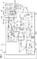
- FIG. 1 in which an access arrangement ZAO is shown, which is designed for use in a vehicle FZ, in particular a motor vehicle.
- the access arrangement ZAO in this case comprises a part on the vehicle which is accommodated in the vehicle FZ, in particular in a door FZT of the vehicle.
- the access arrangement ZAO also has a mobile part which is formed by a mobile identification transmitter, here in the form of a smartphone (intelligent telephone) SP.
- a vehicle-side control device STE (for example in the form of a microcontroller) will send a signal via a control line SLN to a vehicle-side transceiver NFF, which then sends request signals CN at regular time intervals.
- a control device STE outside the vehicle-side transceiver
- a control device STN integrated in the vehicle-side transceiver takes over the task of the control device STE.
- the vehicle-side transceiver is an NFC module or an NFC reader NFF, which is installed adjacent to or at least partially in a door handle TG of the vehicle door FZT.
- This NFC reader NFF will now transmit radio signals, in particular with a short range of approximately 10 cm, as request signals CN. These radio signals for request and response are in a frequency range according to an NFC standard, in particular at 13.56 MHz.
- the smartphone SP If there is now a radio-technical counterpart, such as the smartphone SP, within the range of the request signals CN, it will respond to these request signals CN with one or more response signals RN.
- a radio-technical counterpart such as the smartphone SP
- the smartphone-side antenna ANS is located on the smartphone SP side, which together form an NFC Form interface NFCS.
- the request signals CN are received by the antenna ANS on the smartphone side and passed to a transceiver SES on the smartphone side.
- This code is from the transceiver SES packaged in a response signal RN, so that the identification code CO is transmitted back to the vehicle, more precisely to the antenna ANF. From there, the code is again routed via the control line SLN to the vehicle-side control device STE, where it is checked by an authentication section AU1. In this test, the authentication code CO is compared with a code FCO stored in the authentication section AU1, a positive result being obtained if the code matches.
- the control device STE issues a corresponding unlocking signal OES for a correct unlocking at a door control device TSG via a vehicle bus SPI.
- the door control unit TSG is supplied with the battery voltage Vbat from a vehicle battery via the vehicle electrical system or a vehicle power supply. If the door control unit TSG receives the correct unlocking signal OES, it will control a motor MO of a door lock DL of the vehicle door FZT in order to unlock the vehicle door FZT or a corresponding locking mechanism. It is also conceivable that, in addition to the door control device TSG of the vehicle door FZT, further door control devices are caused to unlock the corresponding door locks in the event of further vehicle doors and thus to allow user access to the vehicle or to the passenger cell of the vehicle.
- emergency operation according to one embodiment of the present invention is also conceivable, in particular for performing an unlocking.
- the smartphone SP As the mobile identification transmitter of a user.
- This smartphone SP is able to run several software-based applications ("Applications” or “Apps”).
- Applications or “Apps”
- a corresponding application can be started using one of the three keys TA1, TA2 or TA3.
- the keys can be designed as mechanical keys or as so-called “soft keys” (touch-sensitive sections of a display device).
- the smartphone SP also has a display DSP, in which information about the application currently being executed can be seen.
- the smartphone SP While it is possible that the smartphone SP must be held against the door handle TG for the exchange of radio signals during the proper operation after starting the "access" application, it is conceivable that in emergency operation a user presses the button TA2, for example, to activate the emergency operation to activate. However, it is also conceivable that the smartphone-side transceiver SES independently activates the emergency operation mode if, for example, it starts within a certain time interval after starting the "Access" application. has not received a request signal CN from the vehicle-side antenna ANF.
- the emergency running function in the smartphone SP has been activated in one of the ways described above. It is also believed to be in Fig. 1 it is shown that the smartphone SP is brought near the door handle TG by the user.
- the smartphone-side transceiver SES is now powered by a smartphone-side battery BAS and transmit electromagnetic energy in the form of the radio signals CE in the direction of the vehicle-side antenna ANF.
- This antenna thus serves as a first section of an on-board energy supply device for receiving wirelessly transmitted energy and for converting the transmitted energy into electrical energy.
- the NFC reader NFF which can be regarded as the vehicle-side energy supply device, is now not operated in emergency operation as a reader, but in a transponder mode in which it absorbs energy supplied (from outside).
- the NFC reading device NFF also has a second section ALN, which serves to charge a vehicle-side rechargeable electrical energy storage device SCH in the form of a supercapacitor or ultracapacitor.
- this supercapacitor SCH has a voltage of 5 volts and a capacitance of 3.3 F.
- a voltage supply NVOUT of the NFC reader NFF provides a voltage supply for an emergency operation control device SEE via its voltage input SVIN, and a voltage supply for a charge trigger circuit CST via its voltage input CVIN.
- the vehicle-side emergency control device SEE Since the operation of the vehicle-side emergency control device SEE is now ensured via the supercapacitor SCH, it can begin to initiate an authentication process with respect to the smartphone SP. For this purpose, a corresponding signal can be output to the NFC reading device NFF via the control line STE, via the control line STE, via the control line STE, which then results in an exchange of request signals CN and response signals RN and a corresponding exchange of the identification code CO begins.
- the identification code CO transmitted by the smartphone can then be checked by an authentication section AU2 of the emergency control device SEE (corresponding to the authentication section AU1 of the control device STE).
- an authentication device in the form of the vehicle-side emergency control device SEE with the corresponding authentication section AU2 can be operated by charging a corresponding rechargeable electrical energy store SCH on the vehicle.
- the authentication section AU2 determines that the smartphone SP on the door handle TG for the access arrangement ZAO heard, since a comparison of the identification code CO sent with a response signal RN with a code FCO stored in the emergency control device SEE was positive, then she will communicate this positive result of the check to the NFC reader NFF, which will then send an enable signal PS to an input SET Charge trigger circuit CST creates. With this release, the charge trigger circuit CST will apply a start signal NES to one input CEN of the charge circuit CCI.
- a button cell can be used as such a battery BUB, for example, which provides 3 volts as voltage V1.
- the charging circuit CC1 also has a step-up converter AFW to step up the voltage V1 to a voltage V2 of 5 volts.
- the CCI charging circuit begins its operation, i. H. with the step-up of the voltage V1 to the voltage V2 and the provision of this voltage V2 at the output IVOUT.
- This provided voltage V2 is then used to charge another vehicle-side rechargeable electrical energy storage device in the form of a capacitor or supercapacitor SCD.
- the charge trigger circuit CST and the charge circuit CCI can together also be referred to as a charge control device LSE.
- a monitoring circuit in the form of a comparator COMP monitors the charging of the supercapacitor SCD.
- the comparator COMP notifies this termination of the charging process to the charging trigger circuit CST by applying a corresponding termination signal BS to an input REST of the charging trigger circuit CST.
- This termination signal BS causes the charge trigger circuit to terminate the application of the start signal NES at the input CEN of the charging circuit CCI, so that the supercapacitor SCD is not further charged.
- the termination signal BS at an input DEN of a switch DCS causes it to establish a connection between its voltage input DVIN, which is connected to the supercapacitor SCD, and its voltage output DVOUT.
- the door lock DL or a corresponding actuator or motor MO is now operated in order to unlock the door lock or a corresponding locking mechanism, and thus also to unlock the vehicle door FZT in an emergency, and one Allow users access to the vehicle interior.
- the emergency control device SEE will have to be charged in an emergency operation mode by the NFC interface NFCS, with the energy of the battery BUB for charging the supercapacitor SCD being immediately charged after the positive authentication Operation of the door lock or the unlocking device DL can be used.
Landscapes
- Engineering & Computer Science (AREA)
- Power Engineering (AREA)
- Mechanical Engineering (AREA)
- Computer Networks & Wireless Communication (AREA)
- Physics & Mathematics (AREA)
- General Physics & Mathematics (AREA)
- Lock And Its Accessories (AREA)
Claims (14)
- Dispositif d'accès (ZAO) destiné à un véhicule {FZ) et comportant les éléments caractéristiques suivants :- un moyen de déverrouillage côté véhicule (DCS, DL) destiné à actionner un mécanisme de blocage (MO) ;- un moyen accumulateur d'énergie électrique rechargeable côté véhicule (SCD) qui est conçu pour alimenter en énergie le moyen de déverrouillage (DCS, DL) ;- un moyen accumulateur d'énergie électrique chargé côté véhicule (BUB) qui est conçu pour charger le moyen accumulateur d'énergie électrique rechargeable côté véhicule (SCD) ;- un moyen de commande de charge (CST, CCI) destiné à commander le processus de charge du moyen accumulateur d'énergie électrique rechargeable côté véhicule (SCD) par le moyen accumulateur d'énergie électrique chargé côté véhicule (BUB), caractérisé par
un moyen d'authentification côté véhicule (SEE) destiné à vérifier une autorisation d'accès et à commander le moyen de commande de charge (CST, CCI) en fonction de la vérification de l'autorisation d'accès. - Dispositif d'accès selon la revendication 1, dans lequel le moyen accumulateur d'énergie électrique chargé côté véhicule (BUB) comporte une cellule galvanique, se présentant en particulier sous la forme d'une cellule primaire.
- Dispositif d'accès selon la revendication 1 ou 2, dans lequel le moyen accumulateur d'énergie électrique rechargeable côté véhicule comprend une batterie rechargeable ou un condensateur, se présentant notamment sous la forme d'un supercondensateur (SCD).
- Dispositif d'accès selon l'une des revendications 1 à 3, dans lequel le moyen de commande de charge (CST, CCI) comporte un convertisseur de tension continue se présentant sous la forme d'un convertisseur élévateur (AFW) pour convertir une première tension (V1), fournie par le moyen accumulateur d'énergie électrique côté véhicule chargé (BUB), en une deuxième tension (V2), supérieure à celle-ci, destinée à charger le moyen accumulateur d'énergie électrique rechargeable côté véhicule (SCD).
- Dispositif d'accès selon l'une des revendications 1 à 4, comprenant en outre un moyen d'alimentation en énergie côté véhicule (NFF) présentant les éléments caractéristiques suivants :- une première portion (ANF) destinée à recevoir l'énergie (CE) transmise sans fil et à convertir l'énergie transmise en énergie électrique, et- une deuxième portion (ALN) destinée à alimenter le moyen d'authentification côté véhicule (SEE) en énergie électrique.
- Dispositif d'accès selon la revendication 5, comprenant en outre un autre moyen accumulateur d'énergie électrique rechargeable côté véhicule (SCH) qui est relié à la deuxième portion (ALN) du moyen d'alimentation en énergie côté véhicule (NFF) afin d'être chargé.
- Dispositif d'accès selon la revendication 6, dans lequel l'autre moyen accumulateur d'énergie électrique rechargeable côté véhicule (SCH) est également conçu pour alimenter le moyen d'authentification côté véhicule (SEE).
- Dispositif d'accès selon l'une des revendications 1 à 7, dans lequel le moyen d'alimentation en énergie côté véhicule (NFF) comprend une interface radio, se présentant notamment sous la forme d'une interface NFC, afin de recevoir l'énergie (CE) transmise sans fil par radio.
- Dispositif d'accès selon l'une des revendications 1 à 8, dans lequel le moyen d'alimentation en énergie côté véhicule comporte une interface lumineuse, se présentant notamment sous la forme d'une cellule photoélectrique, afin de recevoir l'énergie transmise sans fil au moyen de la lumière.
- Dispositif d'accès selon l'une des revendications 1 à 9, dans lequel le moyen d'authentification côté véhicule (SEE) destiné à effectuer l'autorisation d'accès émet un signal de déverrouillage (PS) pour activer le moyen de déverrouillage côté véhicule.
- Dispositif d'accès selon l'une des revendications 1 à 10, lequel comporte également un émetteur d'identification mobile (SP) destiné à délivrer l'énergie (CE), transmise sans fil, au moyen d'alimentation en énergie côté véhicule (NFF, ANF).
- Dispositif d'accès selon la revendication 11, dans lequel l'émetteur d'identification mobile (SP) est également conçu pour effectuer une authentification avec le moyen d'authentification côté véhicule (SEE).
- Dispositif d'accès selon la revendication 11 ou 12, dans lequel l'émetteur d'identification mobile est conçu comme une clé, un porte-clés, un téléphone portable, un smartphone (SP) ou un traqueur d'activité sportive.
- Véhicule comprenant un dispositif d'accès selon l'une des revendications 1 à 13.
Priority Applications (4)
| Application Number | Priority Date | Filing Date | Title |
|---|---|---|---|
| EP17465536.5A EP3441267B1 (fr) | 2017-08-11 | 2017-08-11 | Système d'accès pour un véhicule |
| CN201880048509.XA CN110944883B (zh) | 2017-08-11 | 2018-08-09 | 用于车辆的访问设备 |
| PCT/EP2018/071664 WO2019030339A1 (fr) | 2017-08-11 | 2018-08-09 | Dispositif d'accès pour véhicule |
| US16/638,069 US10864893B2 (en) | 2017-08-11 | 2018-08-09 | Access arrangement for a vehicle |
Applications Claiming Priority (1)
| Application Number | Priority Date | Filing Date | Title |
|---|---|---|---|
| EP17465536.5A EP3441267B1 (fr) | 2017-08-11 | 2017-08-11 | Système d'accès pour un véhicule |
Publications (2)
| Publication Number | Publication Date |
|---|---|
| EP3441267A1 EP3441267A1 (fr) | 2019-02-13 |
| EP3441267B1 true EP3441267B1 (fr) | 2020-06-17 |
Family
ID=59811278
Family Applications (1)
| Application Number | Title | Priority Date | Filing Date |
|---|---|---|---|
| EP17465536.5A Active EP3441267B1 (fr) | 2017-08-11 | 2017-08-11 | Système d'accès pour un véhicule |
Country Status (4)
| Country | Link |
|---|---|
| US (1) | US10864893B2 (fr) |
| EP (1) | EP3441267B1 (fr) |
| CN (1) | CN110944883B (fr) |
| WO (1) | WO2019030339A1 (fr) |
Families Citing this family (8)
| Publication number | Priority date | Publication date | Assignee | Title |
|---|---|---|---|---|
| DE102018106410A1 (de) | 2018-03-19 | 2019-09-19 | Brose Fahrzeugteile Gmbh & Co. Kommanditgesellschaft, Bamberg | Steueranordnung für eine Kraftfahrzeugtür |
| CN113888776A (zh) * | 2020-06-16 | 2022-01-04 | 比亚迪股份有限公司 | 车辆应急解锁装置、系统、方法及车辆 |
| US11951945B1 (en) * | 2020-11-20 | 2024-04-09 | Enterprise Electronics, Llc | NFC-based enclosure access using passive energy harvesting |
| US11741767B1 (en) * | 2020-11-20 | 2023-08-29 | Enterprise Electronics Llc | NFC-based enclosure access using passive energy harvesting |
| US11713022B1 (en) * | 2020-11-20 | 2023-08-01 | Enterprise Electronics Llc | NFC-based enclosure access using passive energy harvesting |
| US11769359B2 (en) * | 2021-07-22 | 2023-09-26 | Rivian Ip Holdings, Llc | Systems, structures, and methods for accessing power locked panels |
| DE102021128395A1 (de) | 2021-10-27 | 2023-04-27 | Elmos Semiconductor Se | Notentriegelungssystem für elektrisch verriegelte Fahrzeugtüren |
| US12247420B2 (en) | 2023-05-30 | 2025-03-11 | Stmicroelectronics International N.V. | Emergency vehicle door opening by harvesting energy from an external field |
Family Cites Families (12)
| Publication number | Priority date | Publication date | Assignee | Title |
|---|---|---|---|---|
| DE4228234A1 (de) | 1992-08-25 | 1994-03-03 | Bayerische Motoren Werke Ag | Türschloß für Kraftfahrzeuge |
| JP4049111B2 (ja) * | 2003-08-21 | 2008-02-20 | 富士電機システムズ株式会社 | 車両用ドア駆動制御装置 |
| DE102005054111A1 (de) * | 2005-11-12 | 2007-05-16 | Marquardt Gmbh | Schließsystem, insbesondere für ein Kraftfahrzeug |
| FR2945162A1 (fr) * | 2009-04-30 | 2010-11-05 | Pascal Metivier | Systeme d'alimentation externe d'une serrure comportant des moyens de communication sans contact de type nfc |
| KR20140144174A (ko) * | 2012-01-05 | 2014-12-18 | 아닥 플라스틱스 인코포레이티드 | 차량 접근 시스템 |
| US8924087B2 (en) | 2012-05-15 | 2014-12-30 | GM Global Technology Operations LLC | Motor vehicle having a centralized door locking system |
| DE202013103042U1 (de) * | 2013-07-09 | 2014-10-10 | Brose Fahrzeugteile Gmbh & Co. Kommanditgesellschaft, Hallstadt | Kraftfahrzeugschloss |
| JP5880582B2 (ja) * | 2014-01-10 | 2016-03-09 | トヨタ自動車株式会社 | 車両 |
| US9805534B2 (en) * | 2014-12-23 | 2017-10-31 | Gate Labs Inc. | Increased security electronic lock |
| US10184272B2 (en) * | 2015-07-01 | 2019-01-22 | Dominick S. LEE | Installation-free rechargeable door locking apparatus, systems and methods |
| US9725069B2 (en) * | 2015-10-12 | 2017-08-08 | Ford Global Technologies, Llc | Keyless vehicle systems |
| US10312721B2 (en) * | 2017-06-06 | 2019-06-04 | Ford Global Technologies, Llc | Vehicle unlocking systems devices and methods |
-
2017
- 2017-08-11 EP EP17465536.5A patent/EP3441267B1/fr active Active
-
2018
- 2018-08-09 WO PCT/EP2018/071664 patent/WO2019030339A1/fr not_active Ceased
- 2018-08-09 CN CN201880048509.XA patent/CN110944883B/zh active Active
- 2018-08-09 US US16/638,069 patent/US10864893B2/en active Active
Non-Patent Citations (1)
| Title |
|---|
| None * |
Also Published As
| Publication number | Publication date |
|---|---|
| EP3441267A1 (fr) | 2019-02-13 |
| US10864893B2 (en) | 2020-12-15 |
| US20200216030A1 (en) | 2020-07-09 |
| WO2019030339A1 (fr) | 2019-02-14 |
| CN110944883A (zh) | 2020-03-31 |
| CN110944883B (zh) | 2022-06-10 |
Similar Documents
| Publication | Publication Date | Title |
|---|---|---|
| EP3441267B1 (fr) | Système d'accès pour un véhicule | |
| DE102017214105B4 (de) | Zugangsanordnung für ein Fahrzeug | |
| DE102013216099B4 (de) | System zum aktivieren eines fahrzeugs in einen schlüssel-ein- zustand | |
| DE102012004000A1 (de) | Transponderschlüssel und dadurch gesteuertes Gerät | |
| DE102011116209A1 (de) | Vorrichtung zum Aktivieren und Deaktivieren eines Schließ- und/oder Steuerungssystems, insbesondere für ein Fahrzeug | |
| DE202016102459U1 (de) | Alternativer Sicherungszugang für Fahrzeuge | |
| DE102007010583B4 (de) | Notfallentsperrung von Kraftfahrzeugen | |
| DE102015211445A1 (de) | Drahtloses Ladesystem | |
| EP3519254B1 (fr) | Procédé de détermination de la position d'un dispositif d'accès mobile sur un véhicule | |
| WO2020239795A1 (fr) | Système de déverrouillage et ensemble serrure comprenant un système de déverrouillage de ce type | |
| DE102017214109B4 (de) | Mobiler Identifikationsgeber | |
| DE102017214099A1 (de) | Mobiler Identifikationsgeber | |
| EP3654298A1 (fr) | Dispositif de commande d'accès pour un actionnement d'urgence et procédé associé | |
| DE102015213984A1 (de) | Verfahren zum Bereitstellen von elektrischer Energie für eine Verriegelungssteuerung einer Türvorrichtung | |
| DE102016214674A1 (de) | Verfahren zum Betreiben eines Kraftfahrzeugs und Steuervorrichtung zum Betreiben eines Kraftfahrzeugs | |
| DE102014104032A1 (de) | Abgedichteter Identifikationsgeber | |
| DE112020002302T5 (de) | Reserve-energieversorgung und authentifizierung für elektronische verriegelung | |
| EP2814005A2 (fr) | Clé destinée à l'utilisation d'un dispositif de fermeture d'un véhicule automobile | |
| WO2011006888A2 (fr) | Dispositif de télécommande portable | |
| DE102012101124A1 (de) | Tragbarer Identifikationsgeber für ein passives Zugangssystem eines Kraftfahrzeugs und Verfahren zum energiesparenden Betreiben des Identifikationsgebers | |
| DE102022100882A1 (de) | Ladevorrichtung und Verfahren | |
| WO2009040316A1 (fr) | Système d'accès sans clé à fonction de secours | |
| DE102013207495A1 (de) | Handhabe für einen beweglichen Teil eines Kraftfahrzeugs und Verfahren zur Übertragung von Daten in einem Kraftfahrzeug | |
| DE102022204236B3 (de) | Notentriegelung eines Kraftfahrzeugs | |
| WO2019030385A1 (fr) | Procédé pour faire fonctionner un ensemble d'accès pour un véhicule |
Legal Events
| Date | Code | Title | Description |
|---|---|---|---|
| PUAI | Public reference made under article 153(3) epc to a published international application that has entered the european phase |
Free format text: ORIGINAL CODE: 0009012 |
|
| STAA | Information on the status of an ep patent application or granted ep patent |
Free format text: STATUS: THE APPLICATION HAS BEEN PUBLISHED |
|
| AK | Designated contracting states |
Kind code of ref document: A1 Designated state(s): AL AT BE BG CH CY CZ DE DK EE ES FI FR GB GR HR HU IE IS IT LI LT LU LV MC MK MT NL NO PL PT RO RS SE SI SK SM TR |
|
| AX | Request for extension of the european patent |
Extension state: BA ME |
|
| STAA | Information on the status of an ep patent application or granted ep patent |
Free format text: STATUS: REQUEST FOR EXAMINATION WAS MADE |
|
| 17P | Request for examination filed |
Effective date: 20190813 |
|
| RBV | Designated contracting states (corrected) |
Designated state(s): AL AT BE BG CH CY CZ DE DK EE ES FI FR GB GR HR HU IE IS IT LI LT LU LV MC MK MT NL NO PL PT RO RS SE SI SK SM TR |
|
| GRAP | Despatch of communication of intention to grant a patent |
Free format text: ORIGINAL CODE: EPIDOSNIGR1 |
|
| STAA | Information on the status of an ep patent application or granted ep patent |
Free format text: STATUS: GRANT OF PATENT IS INTENDED |
|
| INTG | Intention to grant announced |
Effective date: 20200116 |
|
| GRAS | Grant fee paid |
Free format text: ORIGINAL CODE: EPIDOSNIGR3 |
|
| GRAA | (expected) grant |
Free format text: ORIGINAL CODE: 0009210 |
|
| STAA | Information on the status of an ep patent application or granted ep patent |
Free format text: STATUS: THE PATENT HAS BEEN GRANTED |
|
| AK | Designated contracting states |
Kind code of ref document: B1 Designated state(s): AL AT BE BG CH CY CZ DE DK EE ES FI FR GB GR HR HU IE IS IT LI LT LU LV MC MK MT NL NO PL PT RO RS SE SI SK SM TR |
|
| REG | Reference to a national code |
Ref country code: GB Ref legal event code: FG4D Free format text: NOT ENGLISH |
|
| REG | Reference to a national code |
Ref country code: CH Ref legal event code: EP |
|
| REG | Reference to a national code |
Ref country code: DE Ref legal event code: R096 Ref document number: 502017005735 Country of ref document: DE |
|
| REG | Reference to a national code |
Ref country code: IE Ref legal event code: FG4D Free format text: LANGUAGE OF EP DOCUMENT: GERMAN |
|
| REG | Reference to a national code |
Ref country code: AT Ref legal event code: REF Ref document number: 1280929 Country of ref document: AT Kind code of ref document: T Effective date: 20200715 |
|
| PG25 | Lapsed in a contracting state [announced via postgrant information from national office to epo] |
Ref country code: GR Free format text: LAPSE BECAUSE OF FAILURE TO SUBMIT A TRANSLATION OF THE DESCRIPTION OR TO PAY THE FEE WITHIN THE PRESCRIBED TIME-LIMIT Effective date: 20200918 Ref country code: NO Free format text: LAPSE BECAUSE OF FAILURE TO SUBMIT A TRANSLATION OF THE DESCRIPTION OR TO PAY THE FEE WITHIN THE PRESCRIBED TIME-LIMIT Effective date: 20200917 Ref country code: LT Free format text: LAPSE BECAUSE OF FAILURE TO SUBMIT A TRANSLATION OF THE DESCRIPTION OR TO PAY THE FEE WITHIN THE PRESCRIBED TIME-LIMIT Effective date: 20200617 Ref country code: SE Free format text: LAPSE BECAUSE OF FAILURE TO SUBMIT A TRANSLATION OF THE DESCRIPTION OR TO PAY THE FEE WITHIN THE PRESCRIBED TIME-LIMIT Effective date: 20200617 Ref country code: FI Free format text: LAPSE BECAUSE OF FAILURE TO SUBMIT A TRANSLATION OF THE DESCRIPTION OR TO PAY THE FEE WITHIN THE PRESCRIBED TIME-LIMIT Effective date: 20200617 |
|
| REG | Reference to a national code |
Ref country code: LT Ref legal event code: MG4D |
|
| REG | Reference to a national code |
Ref country code: NL Ref legal event code: MP Effective date: 20200617 |
|
| PG25 | Lapsed in a contracting state [announced via postgrant information from national office to epo] |
Ref country code: BG Free format text: LAPSE BECAUSE OF FAILURE TO SUBMIT A TRANSLATION OF THE DESCRIPTION OR TO PAY THE FEE WITHIN THE PRESCRIBED TIME-LIMIT Effective date: 20200917 Ref country code: HR Free format text: LAPSE BECAUSE OF FAILURE TO SUBMIT A TRANSLATION OF THE DESCRIPTION OR TO PAY THE FEE WITHIN THE PRESCRIBED TIME-LIMIT Effective date: 20200617 Ref country code: LV Free format text: LAPSE BECAUSE OF FAILURE TO SUBMIT A TRANSLATION OF THE DESCRIPTION OR TO PAY THE FEE WITHIN THE PRESCRIBED TIME-LIMIT Effective date: 20200617 Ref country code: RS Free format text: LAPSE BECAUSE OF FAILURE TO SUBMIT A TRANSLATION OF THE DESCRIPTION OR TO PAY THE FEE WITHIN THE PRESCRIBED TIME-LIMIT Effective date: 20200617 |
|
| PG25 | Lapsed in a contracting state [announced via postgrant information from national office to epo] |
Ref country code: AL Free format text: LAPSE BECAUSE OF FAILURE TO SUBMIT A TRANSLATION OF THE DESCRIPTION OR TO PAY THE FEE WITHIN THE PRESCRIBED TIME-LIMIT Effective date: 20200617 Ref country code: NL Free format text: LAPSE BECAUSE OF FAILURE TO SUBMIT A TRANSLATION OF THE DESCRIPTION OR TO PAY THE FEE WITHIN THE PRESCRIBED TIME-LIMIT Effective date: 20200617 |
|
| PG25 | Lapsed in a contracting state [announced via postgrant information from national office to epo] |
Ref country code: PT Free format text: LAPSE BECAUSE OF FAILURE TO SUBMIT A TRANSLATION OF THE DESCRIPTION OR TO PAY THE FEE WITHIN THE PRESCRIBED TIME-LIMIT Effective date: 20201019 Ref country code: ES Free format text: LAPSE BECAUSE OF FAILURE TO SUBMIT A TRANSLATION OF THE DESCRIPTION OR TO PAY THE FEE WITHIN THE PRESCRIBED TIME-LIMIT Effective date: 20200617 Ref country code: RO Free format text: LAPSE BECAUSE OF FAILURE TO SUBMIT A TRANSLATION OF THE DESCRIPTION OR TO PAY THE FEE WITHIN THE PRESCRIBED TIME-LIMIT Effective date: 20200617 Ref country code: IT Free format text: LAPSE BECAUSE OF FAILURE TO SUBMIT A TRANSLATION OF THE DESCRIPTION OR TO PAY THE FEE WITHIN THE PRESCRIBED TIME-LIMIT Effective date: 20200617 Ref country code: CZ Free format text: LAPSE BECAUSE OF FAILURE TO SUBMIT A TRANSLATION OF THE DESCRIPTION OR TO PAY THE FEE WITHIN THE PRESCRIBED TIME-LIMIT Effective date: 20200617 Ref country code: SM Free format text: LAPSE BECAUSE OF FAILURE TO SUBMIT A TRANSLATION OF THE DESCRIPTION OR TO PAY THE FEE WITHIN THE PRESCRIBED TIME-LIMIT Effective date: 20200617 Ref country code: EE Free format text: LAPSE BECAUSE OF FAILURE TO SUBMIT A TRANSLATION OF THE DESCRIPTION OR TO PAY THE FEE WITHIN THE PRESCRIBED TIME-LIMIT Effective date: 20200617 |
|
| PG25 | Lapsed in a contracting state [announced via postgrant information from national office to epo] |
Ref country code: SK Free format text: LAPSE BECAUSE OF FAILURE TO SUBMIT A TRANSLATION OF THE DESCRIPTION OR TO PAY THE FEE WITHIN THE PRESCRIBED TIME-LIMIT Effective date: 20200617 Ref country code: PL Free format text: LAPSE BECAUSE OF FAILURE TO SUBMIT A TRANSLATION OF THE DESCRIPTION OR TO PAY THE FEE WITHIN THE PRESCRIBED TIME-LIMIT Effective date: 20200617 Ref country code: IS Free format text: LAPSE BECAUSE OF FAILURE TO SUBMIT A TRANSLATION OF THE DESCRIPTION OR TO PAY THE FEE WITHIN THE PRESCRIBED TIME-LIMIT Effective date: 20201017 |
|
| REG | Reference to a national code |
Ref country code: DE Ref legal event code: R097 Ref document number: 502017005735 Country of ref document: DE |
|
| PG25 | Lapsed in a contracting state [announced via postgrant information from national office to epo] |
Ref country code: MC Free format text: LAPSE BECAUSE OF FAILURE TO SUBMIT A TRANSLATION OF THE DESCRIPTION OR TO PAY THE FEE WITHIN THE PRESCRIBED TIME-LIMIT Effective date: 20200617 |
|
| REG | Reference to a national code |
Ref country code: CH Ref legal event code: PL |
|
| PLBE | No opposition filed within time limit |
Free format text: ORIGINAL CODE: 0009261 |
|
| STAA | Information on the status of an ep patent application or granted ep patent |
Free format text: STATUS: NO OPPOSITION FILED WITHIN TIME LIMIT |
|
| PG25 | Lapsed in a contracting state [announced via postgrant information from national office to epo] |
Ref country code: CH Free format text: LAPSE BECAUSE OF NON-PAYMENT OF DUE FEES Effective date: 20200831 Ref country code: DK Free format text: LAPSE BECAUSE OF FAILURE TO SUBMIT A TRANSLATION OF THE DESCRIPTION OR TO PAY THE FEE WITHIN THE PRESCRIBED TIME-LIMIT Effective date: 20200617 Ref country code: LU Free format text: LAPSE BECAUSE OF NON-PAYMENT OF DUE FEES Effective date: 20200811 Ref country code: LI Free format text: LAPSE BECAUSE OF NON-PAYMENT OF DUE FEES Effective date: 20200831 |
|
| 26N | No opposition filed |
Effective date: 20210318 |
|
| REG | Reference to a national code |
Ref country code: BE Ref legal event code: MM Effective date: 20200831 |
|
| PG25 | Lapsed in a contracting state [announced via postgrant information from national office to epo] |
Ref country code: SI Free format text: LAPSE BECAUSE OF FAILURE TO SUBMIT A TRANSLATION OF THE DESCRIPTION OR TO PAY THE FEE WITHIN THE PRESCRIBED TIME-LIMIT Effective date: 20200617 |
|
| PG25 | Lapsed in a contracting state [announced via postgrant information from national office to epo] |
Ref country code: BE Free format text: LAPSE BECAUSE OF NON-PAYMENT OF DUE FEES Effective date: 20200831 Ref country code: IE Free format text: LAPSE BECAUSE OF NON-PAYMENT OF DUE FEES Effective date: 20200811 |
|
| PG25 | Lapsed in a contracting state [announced via postgrant information from national office to epo] |
Ref country code: TR Free format text: LAPSE BECAUSE OF FAILURE TO SUBMIT A TRANSLATION OF THE DESCRIPTION OR TO PAY THE FEE WITHIN THE PRESCRIBED TIME-LIMIT Effective date: 20200617 Ref country code: MT Free format text: LAPSE BECAUSE OF FAILURE TO SUBMIT A TRANSLATION OF THE DESCRIPTION OR TO PAY THE FEE WITHIN THE PRESCRIBED TIME-LIMIT Effective date: 20200617 Ref country code: CY Free format text: LAPSE BECAUSE OF FAILURE TO SUBMIT A TRANSLATION OF THE DESCRIPTION OR TO PAY THE FEE WITHIN THE PRESCRIBED TIME-LIMIT Effective date: 20200617 |
|
| PG25 | Lapsed in a contracting state [announced via postgrant information from national office to epo] |
Ref country code: MK Free format text: LAPSE BECAUSE OF FAILURE TO SUBMIT A TRANSLATION OF THE DESCRIPTION OR TO PAY THE FEE WITHIN THE PRESCRIBED TIME-LIMIT Effective date: 20200617 |
|
| REG | Reference to a national code |
Ref country code: DE Ref legal event code: R081 Ref document number: 502017005735 Country of ref document: DE Owner name: CONTINENTAL AUTOMOTIVE TECHNOLOGIES GMBH, DE Free format text: FORMER OWNER: CONTINENTAL AUTOMOTIVE GMBH, 30165 HANNOVER, DE Ref country code: DE Ref legal event code: R081 Ref document number: 502017005735 Country of ref document: DE Owner name: AUMOVIO GERMANY GMBH, DE Free format text: FORMER OWNER: CONTINENTAL AUTOMOTIVE GMBH, 30165 HANNOVER, DE |
|
| REG | Reference to a national code |
Ref country code: GB Ref legal event code: 732E Free format text: REGISTERED BETWEEN 20230223 AND 20230301 |
|
| REG | Reference to a national code |
Ref country code: AT Ref legal event code: MM01 Ref document number: 1280929 Country of ref document: AT Kind code of ref document: T Effective date: 20220811 |
|
| PG25 | Lapsed in a contracting state [announced via postgrant information from national office to epo] |
Ref country code: AT Free format text: LAPSE BECAUSE OF NON-PAYMENT OF DUE FEES Effective date: 20220811 |
|
| REG | Reference to a national code |
Ref country code: DE Ref legal event code: R081 Ref document number: 502017005735 Country of ref document: DE Owner name: CONTINENTAL AUTOMOTIVE TECHNOLOGIES GMBH, DE Free format text: FORMER OWNER: CONTINENTAL AUTOMOTIVE TECHNOLOGIES GMBH, 30165 HANNOVER, DE Ref country code: DE Ref legal event code: R081 Ref document number: 502017005735 Country of ref document: DE Owner name: AUMOVIO GERMANY GMBH, DE Free format text: FORMER OWNER: CONTINENTAL AUTOMOTIVE TECHNOLOGIES GMBH, 30165 HANNOVER, DE |
|
| PGFP | Annual fee paid to national office [announced via postgrant information from national office to epo] |
Ref country code: DE Payment date: 20250831 Year of fee payment: 9 |
|
| PGFP | Annual fee paid to national office [announced via postgrant information from national office to epo] |
Ref country code: GB Payment date: 20250821 Year of fee payment: 9 |
|
| PGFP | Annual fee paid to national office [announced via postgrant information from national office to epo] |
Ref country code: FR Payment date: 20250828 Year of fee payment: 9 |
|
| REG | Reference to a national code |
Ref country code: DE Ref legal event code: R081 Ref document number: 502017005735 Country of ref document: DE Owner name: AUMOVIO GERMANY GMBH, DE Free format text: FORMER OWNER: CONTINENTAL AUTOMOTIVE TECHNOLOGIES GMBH, 30175 HANNOVER, DE |