EP3441265B1 - Curtain airbag device mounting structure and curtain airbag deployment method - Google Patents
Curtain airbag device mounting structure and curtain airbag deployment method Download PDFInfo
- Publication number
- EP3441265B1 EP3441265B1 EP18180533.4A EP18180533A EP3441265B1 EP 3441265 B1 EP3441265 B1 EP 3441265B1 EP 18180533 A EP18180533 A EP 18180533A EP 3441265 B1 EP3441265 B1 EP 3441265B1
- Authority
- EP
- European Patent Office
- Prior art keywords
- pillar
- curtain airbag
- vehicle
- garnish
- side garnish
- Prior art date
- Legal status (The legal status is an assumption and is not a legal conclusion. Google has not performed a legal analysis and makes no representation as to the accuracy of the status listed.)
- Active
Links
Images
Classifications
-
- B—PERFORMING OPERATIONS; TRANSPORTING
- B60—VEHICLES IN GENERAL
- B60R—VEHICLES, VEHICLE FITTINGS, OR VEHICLE PARTS, NOT OTHERWISE PROVIDED FOR
- B60R13/00—Elements for body-finishing, identifying, or decorating; Arrangements or adaptations for advertising purposes
- B60R13/02—Internal Trim mouldings ; Internal Ledges; Wall liners for passenger compartments; Roof liners
- B60R13/0237—Side or rear panels
- B60R13/025—Pillars; Roof rails
-
- B—PERFORMING OPERATIONS; TRANSPORTING
- B60—VEHICLES IN GENERAL
- B60R—VEHICLES, VEHICLE FITTINGS, OR VEHICLE PARTS, NOT OTHERWISE PROVIDED FOR
- B60R21/00—Arrangements or fittings on vehicles for protecting or preventing injuries to occupants or pedestrians in case of accidents or other traffic risks
- B60R21/02—Occupant safety arrangements or fittings, e.g. crash pads
- B60R21/16—Inflatable occupant restraints or confinements designed to inflate upon impact or impending impact, e.g. air bags
- B60R21/23—Inflatable members
- B60R21/231—Inflatable members characterised by their shape, construction or spatial configuration
- B60R21/232—Curtain-type airbags deploying mainly in a vertical direction from their top edge
-
- B—PERFORMING OPERATIONS; TRANSPORTING
- B60—VEHICLES IN GENERAL
- B60R—VEHICLES, VEHICLE FITTINGS, OR VEHICLE PARTS, NOT OTHERWISE PROVIDED FOR
- B60R13/00—Elements for body-finishing, identifying, or decorating; Arrangements or adaptations for advertising purposes
- B60R13/02—Internal Trim mouldings ; Internal Ledges; Wall liners for passenger compartments; Roof liners
-
- A—HUMAN NECESSITIES
- A46—BRUSHWARE
- A46B—BRUSHES
- A46B11/00—Brushes with reservoir or other means for applying substances, e.g. paints, pastes, water
- A46B11/0072—Details
- A46B11/0079—Arrangements for preventing undesired leakage or dispensing
- A46B11/0082—Means for closing, sealing or controlling the flow using capillary action
-
- A—HUMAN NECESSITIES
- A47—FURNITURE; DOMESTIC ARTICLES OR APPLIANCES; COFFEE MILLS; SPICE MILLS; SUCTION CLEANERS IN GENERAL
- A47F—SPECIAL FURNITURE, FITTINGS, OR ACCESSORIES FOR SHOPS, STOREHOUSES, BARS, RESTAURANTS OR THE LIKE; PAYING COUNTERS
- A47F11/00—Arrangements in shop windows, shop floors or show cases
- A47F11/02—Removable walls, scaffolding or the like; Pillars; Special curtains or the like
-
- A—HUMAN NECESSITIES
- A47—FURNITURE; DOMESTIC ARTICLES OR APPLIANCES; COFFEE MILLS; SPICE MILLS; SUCTION CLEANERS IN GENERAL
- A47F—SPECIAL FURNITURE, FITTINGS, OR ACCESSORIES FOR SHOPS, STOREHOUSES, BARS, RESTAURANTS OR THE LIKE; PAYING COUNTERS
- A47F5/00—Show stands, hangers, or shelves characterised by their constructional features
- A47F5/04—Stands with a central pillar, e.g. tree type
- A47F5/05—Stands with a central pillar, e.g. tree type with separate containers rotatable around the pillar
-
- A—HUMAN NECESSITIES
- A47—FURNITURE; DOMESTIC ARTICLES OR APPLIANCES; COFFEE MILLS; SPICE MILLS; SUCTION CLEANERS IN GENERAL
- A47F—SPECIAL FURNITURE, FITTINGS, OR ACCESSORIES FOR SHOPS, STOREHOUSES, BARS, RESTAURANTS OR THE LIKE; PAYING COUNTERS
- A47F5/00—Show stands, hangers, or shelves characterised by their constructional features
- A47F5/10—Adjustable or foldable or dismountable display stands
- A47F5/106—Adjustable or foldable or dismountable display stands with independent pillars
-
- A—HUMAN NECESSITIES
- A61—MEDICAL OR VETERINARY SCIENCE; HYGIENE
- A61B—DIAGNOSIS; SURGERY; IDENTIFICATION
- A61B5/00—Measuring for diagnostic purposes; Identification of persons
- A61B5/02—Detecting, measuring or recording for evaluating the cardiovascular system, e.g. pulse, heart rate, blood pressure or blood flow
- A61B5/02007—Evaluating blood vessel condition, e.g. elasticity, compliance
- A61B5/02021—Determining capillary fragility
-
- A—HUMAN NECESSITIES
- A61—MEDICAL OR VETERINARY SCIENCE; HYGIENE
- A61B—DIAGNOSIS; SURGERY; IDENTIFICATION
- A61B5/00—Measuring for diagnostic purposes; Identification of persons
- A61B5/15—Devices for taking samples of blood
- A61B5/150007—Details
- A61B5/150015—Source of blood
- A61B5/150022—Source of blood for capillary blood or interstitial fluid
-
- A—HUMAN NECESSITIES
- A61—MEDICAL OR VETERINARY SCIENCE; HYGIENE
- A61B—DIAGNOSIS; SURGERY; IDENTIFICATION
- A61B5/00—Measuring for diagnostic purposes; Identification of persons
- A61B5/15—Devices for taking samples of blood
- A61B5/150007—Details
- A61B5/150374—Details of piercing elements or protective means for preventing accidental injuries by such piercing elements
- A61B5/150381—Design of piercing elements
- A61B5/150412—Pointed piercing elements, e.g. needles, lancets for piercing the skin
- A61B5/150419—Pointed piercing elements, e.g. needles, lancets for piercing the skin comprising means for capillary action
-
- A—HUMAN NECESSITIES
- A61—MEDICAL OR VETERINARY SCIENCE; HYGIENE
- A61B—DIAGNOSIS; SURGERY; IDENTIFICATION
- A61B5/00—Measuring for diagnostic purposes; Identification of persons
- A61B5/15—Devices for taking samples of blood
- A61B5/150007—Details
- A61B5/150374—Details of piercing elements or protective means for preventing accidental injuries by such piercing elements
- A61B5/150381—Design of piercing elements
- A61B5/150442—Blade-like piercing elements, e.g. blades, cutters, knives, for cutting the skin
- A61B5/15045—Blade-like piercing elements, e.g. blades, cutters, knives, for cutting the skin comprising means for capillary action
-
- A—HUMAN NECESSITIES
- A61—MEDICAL OR VETERINARY SCIENCE; HYGIENE
- A61B—DIAGNOSIS; SURGERY; IDENTIFICATION
- A61B5/00—Measuring for diagnostic purposes; Identification of persons
- A61B5/15—Devices for taking samples of blood
- A61B5/151—Devices specially adapted for taking samples of capillary blood, e.g. by lancets, needles or blades
- A61B5/15134—Bladeless capillary blood sampling devices, i.e. devices for perforating the skin in order to obtain a blood sample but not using a blade, needle, canula, or lancet, e.g. by laser perforation, suction or pressurized fluids
-
- A—HUMAN NECESSITIES
- A61—MEDICAL OR VETERINARY SCIENCE; HYGIENE
- A61M—DEVICES FOR INTRODUCING MEDIA INTO, OR ONTO, THE BODY; DEVICES FOR TRANSDUCING BODY MEDIA OR FOR TAKING MEDIA FROM THE BODY; DEVICES FOR PRODUCING OR ENDING SLEEP OR STUPOR
- A61M5/00—Devices for bringing media into the body in a subcutaneous, intra-vascular or intramuscular way; Accessories therefor, e.g. filling or cleaning devices, arm-rests
- A61M5/14—Infusion devices, e.g. infusing by gravity; Blood infusion; Accessories therefor
- A61M5/141—Infusion devices, e.g. infusing by gravity; Blood infusion; Accessories therefor with capillaries for restricting fluid flow
-
- B—PERFORMING OPERATIONS; TRANSPORTING
- B01—PHYSICAL OR CHEMICAL PROCESSES OR APPARATUS IN GENERAL
- B01J—CHEMICAL OR PHYSICAL PROCESSES, e.g. CATALYSIS OR COLLOID CHEMISTRY; THEIR RELEVANT APPARATUS
- B01J19/00—Chemical, physical or physico-chemical processes in general; Their relevant apparatus
- B01J19/0093—Microreactors, e.g. miniaturised or microfabricated reactors
-
- B—PERFORMING OPERATIONS; TRANSPORTING
- B01—PHYSICAL OR CHEMICAL PROCESSES OR APPARATUS IN GENERAL
- B01J—CHEMICAL OR PHYSICAL PROCESSES, e.g. CATALYSIS OR COLLOID CHEMISTRY; THEIR RELEVANT APPARATUS
- B01J29/00—Catalysts comprising molecular sieves
- B01J29/04—Catalysts comprising molecular sieves having base-exchange properties, e.g. crystalline zeolites
- B01J29/049—Pillared clays
-
- B—PERFORMING OPERATIONS; TRANSPORTING
- B21—MECHANICAL METAL-WORKING WITHOUT ESSENTIALLY REMOVING MATERIAL; PUNCHING METAL
- B21D—WORKING OR PROCESSING OF SHEET METAL OR METAL TUBES, RODS OR PROFILES WITHOUT ESSENTIALLY REMOVING MATERIAL; PUNCHING METAL
- B21D37/00—Tools as parts of machines covered by this subclass
- B21D37/10—Die sets; Pillar guides
-
- B—PERFORMING OPERATIONS; TRANSPORTING
- B21—MECHANICAL METAL-WORKING WITHOUT ESSENTIALLY REMOVING MATERIAL; PUNCHING METAL
- B21D—WORKING OR PROCESSING OF SHEET METAL OR METAL TUBES, RODS OR PROFILES WITHOUT ESSENTIALLY REMOVING MATERIAL; PUNCHING METAL
- B21D47/00—Making rigid structural elements or units, e.g. honeycomb structures
- B21D47/01—Making rigid structural elements or units, e.g. honeycomb structures beams or pillars
-
- B—PERFORMING OPERATIONS; TRANSPORTING
- B22—CASTING; POWDER METALLURGY
- B22D—CASTING OF METALS; CASTING OF OTHER SUBSTANCES BY THE SAME PROCESSES OR DEVICES
- B22D11/00—Continuous casting of metals, i.e. casting in indefinite lengths
- B22D11/06—Continuous casting of metals, i.e. casting in indefinite lengths into moulds with travelling walls, e.g. with rolls, plates, belts, caterpillars
- B22D11/0608—Continuous casting of metals, i.e. casting in indefinite lengths into moulds with travelling walls, e.g. with rolls, plates, belts, caterpillars formed by caterpillars
-
- B—PERFORMING OPERATIONS; TRANSPORTING
- B22—CASTING; POWDER METALLURGY
- B22D—CASTING OF METALS; CASTING OF OTHER SUBSTANCES BY THE SAME PROCESSES OR DEVICES
- B22D11/00—Continuous casting of metals, i.e. casting in indefinite lengths
- B22D11/06—Continuous casting of metals, i.e. casting in indefinite lengths into moulds with travelling walls, e.g. with rolls, plates, belts, caterpillars
- B22D11/0637—Accessories therefor
- B22D11/0648—Casting surfaces
- B22D11/0657—Caterpillars
-
- B—PERFORMING OPERATIONS; TRANSPORTING
- B22—CASTING; POWDER METALLURGY
- B22D—CASTING OF METALS; CASTING OF OTHER SUBSTANCES BY THE SAME PROCESSES OR DEVICES
- B22D11/00—Continuous casting of metals, i.e. casting in indefinite lengths
- B22D11/06—Continuous casting of metals, i.e. casting in indefinite lengths into moulds with travelling walls, e.g. with rolls, plates, belts, caterpillars
- B22D11/0637—Accessories therefor
- B22D11/068—Accessories therefor for cooling the cast product during its passage through the mould surfaces
- B22D11/0688—Accessories therefor for cooling the cast product during its passage through the mould surfaces by cooling the caterpillars
-
- B—PERFORMING OPERATIONS; TRANSPORTING
- B23—MACHINE TOOLS; METAL-WORKING NOT OTHERWISE PROVIDED FOR
- B23D—PLANING; SLOTTING; SHEARING; BROACHING; SAWING; FILING; SCRAPING; LIKE OPERATIONS FOR WORKING METAL BY REMOVING MATERIAL, NOT OTHERWISE PROVIDED FOR
- B23D7/00—Planing or slotting machines characterised only by constructional features of particular parts
- B23D7/04—Planing or slotting machines characterised only by constructional features of particular parts of pillars, of cross-beams
-
- B—PERFORMING OPERATIONS; TRANSPORTING
- B23—MACHINE TOOLS; METAL-WORKING NOT OTHERWISE PROVIDED FOR
- B23K—SOLDERING OR UNSOLDERING; WELDING; CLADDING OR PLATING BY SOLDERING OR WELDING; CUTTING BY APPLYING HEAT LOCALLY, e.g. FLAME CUTTING; WORKING BY LASER BEAM
- B23K20/00—Non-electric welding by applying impact or other pressure, with or without the application of heat, e.g. cladding or plating
- B23K20/002—Non-electric welding by applying impact or other pressure, with or without the application of heat, e.g. cladding or plating specially adapted for particular articles or work
- B23K20/004—Wire welding
- B23K20/005—Capillary welding
-
- B—PERFORMING OPERATIONS; TRANSPORTING
- B25—HAND TOOLS; PORTABLE POWER-DRIVEN TOOLS; MANIPULATORS
- B25D—PERCUSSIVE TOOLS
- B25D17/00—Details of, or accessories for, portable power-driven percussive tools
- B25D17/28—Supports; Devices for holding power-driven percussive tools in working position
- B25D17/30—Pillars and struts
-
- B—PERFORMING OPERATIONS; TRANSPORTING
- B29—WORKING OF PLASTICS; WORKING OF SUBSTANCES IN A PLASTIC STATE IN GENERAL
- B29C—SHAPING OR JOINING OF PLASTICS; SHAPING OF MATERIAL IN A PLASTIC STATE, NOT OTHERWISE PROVIDED FOR; AFTER-TREATMENT OF THE SHAPED PRODUCTS, e.g. REPAIRING
- B29C65/00—Joining or sealing of preformed parts, e.g. welding of plastics materials; Apparatus therefor
- B29C65/48—Joining or sealing of preformed parts, e.g. welding of plastics materials; Apparatus therefor using adhesives, i.e. using supplementary joining material; solvent bonding
- B29C65/52—Joining or sealing of preformed parts, e.g. welding of plastics materials; Apparatus therefor using adhesives, i.e. using supplementary joining material; solvent bonding characterised by the way of applying the adhesive
- B29C65/54—Joining or sealing of preformed parts, e.g. welding of plastics materials; Apparatus therefor using adhesives, i.e. using supplementary joining material; solvent bonding characterised by the way of applying the adhesive between pre-assembled parts
- B29C65/548—Joining or sealing of preformed parts, e.g. welding of plastics materials; Apparatus therefor using adhesives, i.e. using supplementary joining material; solvent bonding characterised by the way of applying the adhesive between pre-assembled parts by capillarity
-
- B—PERFORMING OPERATIONS; TRANSPORTING
- B60—VEHICLES IN GENERAL
- B60H—ARRANGEMENTS OF HEATING, COOLING, VENTILATING OR OTHER AIR-TREATING DEVICES SPECIALLY ADAPTED FOR PASSENGER OR GOODS SPACES OF VEHICLES
- B60H1/00—Heating, cooling or ventilating devices
- B60H1/24—Ventilating devices where the heating or cooling is irrelevant
- B60H1/241—Ventilating devices where the heating or cooling is irrelevant characterised by the location of ventilation devices in the vehicle
- B60H1/243—Ventilating devices where the heating or cooling is irrelevant characterised by the location of ventilation devices in the vehicle located in the lateral area (e.g. doors, pillars)
-
- B—PERFORMING OPERATIONS; TRANSPORTING
- B60—VEHICLES IN GENERAL
- B60H—ARRANGEMENTS OF HEATING, COOLING, VENTILATING OR OTHER AIR-TREATING DEVICES SPECIALLY ADAPTED FOR PASSENGER OR GOODS SPACES OF VEHICLES
- B60H1/00—Heating, cooling or ventilating devices
- B60H1/24—Ventilating devices where the heating or cooling is irrelevant
- B60H1/26—Ventilating openings in vehicle exterior; Ducts for conveying ventilating air
- B60H1/265—Openings in window or door posts or pillars
-
- B—PERFORMING OPERATIONS; TRANSPORTING
- B60—VEHICLES IN GENERAL
- B60J—WINDOWS, WINDSCREENS, NON-FIXED ROOFS, DOORS, OR SIMILAR DEVICES FOR VEHICLES; REMOVABLE EXTERNAL PROTECTIVE COVERINGS SPECIALLY ADAPTED FOR VEHICLES
- B60J10/00—Sealing arrangements
- B60J10/70—Sealing arrangements specially adapted for windows or windscreens
- B60J10/74—Sealing arrangements specially adapted for windows or windscreens for sliding window panes, e.g. sash guides
- B60J10/77—Sealing arrangements specially adapted for windows or windscreens for sliding window panes, e.g. sash guides for sashless windows, i.e. for frameless windows forming a seal directly with the vehicle body
- B60J10/777—Sealing arrangements specially adapted for windows or windscreens for sliding window panes, e.g. sash guides for sashless windows, i.e. for frameless windows forming a seal directly with the vehicle body the sealing arrangement being between the edges of adjacent panes
- B60J10/7775—Sealing arrangements specially adapted for windows or windscreens for sliding window panes, e.g. sash guides for sashless windows, i.e. for frameless windows forming a seal directly with the vehicle body the sealing arrangement being between the edges of adjacent panes mounted on the pillar
-
- B—PERFORMING OPERATIONS; TRANSPORTING
- B60—VEHICLES IN GENERAL
- B60J—WINDOWS, WINDSCREENS, NON-FIXED ROOFS, DOORS, OR SIMILAR DEVICES FOR VEHICLES; REMOVABLE EXTERNAL PROTECTIVE COVERINGS SPECIALLY ADAPTED FOR VEHICLES
- B60J5/00—Doors
- B60J5/04—Doors arranged at the vehicle sides
- B60J5/047—Doors arranged at the vehicle sides characterised by the opening or closing movement
- B60J5/0477—Doors arranged at the vehicle sides characterised by the opening or closing movement with two doors opening in opposite direction
- B60J5/0479—Doors arranged at the vehicle sides characterised by the opening or closing movement with two doors opening in opposite direction without B-pillar or releasable B-pillar, i.e. the pillar is moving with door
-
- B—PERFORMING OPERATIONS; TRANSPORTING
- B60—VEHICLES IN GENERAL
- B60J—WINDOWS, WINDSCREENS, NON-FIXED ROOFS, DOORS, OR SIMILAR DEVICES FOR VEHICLES; REMOVABLE EXTERNAL PROTECTIVE COVERINGS SPECIALLY ADAPTED FOR VEHICLES
- B60J7/00—Non-fixed roofs; Roofs with movable panels, e.g. rotary sunroofs
- B60J7/0076—Non-fixed roofs; Roofs with movable panels, e.g. rotary sunroofs separately collapsible C-pillars, e.g. by folding inwardly or sliding
-
- B—PERFORMING OPERATIONS; TRANSPORTING
- B60—VEHICLES IN GENERAL
- B60R—VEHICLES, VEHICLE FITTINGS, OR VEHICLE PARTS, NOT OTHERWISE PROVIDED FOR
- B60R16/00—Electric or fluid circuits specially adapted for vehicles and not otherwise provided for; Arrangement of elements of electric or fluid circuits specially adapted for vehicles and not otherwise provided for
- B60R16/02—Electric or fluid circuits specially adapted for vehicles and not otherwise provided for; Arrangement of elements of electric or fluid circuits specially adapted for vehicles and not otherwise provided for electric constitutive elements
- B60R16/0207—Wire harnesses
-
- B—PERFORMING OPERATIONS; TRANSPORTING
- B60—VEHICLES IN GENERAL
- B60R—VEHICLES, VEHICLE FITTINGS, OR VEHICLE PARTS, NOT OTHERWISE PROVIDED FOR
- B60R21/00—Arrangements or fittings on vehicles for protecting or preventing injuries to occupants or pedestrians in case of accidents or other traffic risks
- B60R21/01—Electrical circuits for triggering passive safety arrangements, e.g. airbags, safety belt tighteners, in case of vehicle accidents or impending vehicle accidents
- B60R21/013—Electrical circuits for triggering passive safety arrangements, e.g. airbags, safety belt tighteners, in case of vehicle accidents or impending vehicle accidents including means for detecting collisions, impending collisions or roll-over
-
- B—PERFORMING OPERATIONS; TRANSPORTING
- B60—VEHICLES IN GENERAL
- B60R—VEHICLES, VEHICLE FITTINGS, OR VEHICLE PARTS, NOT OTHERWISE PROVIDED FOR
- B60R21/00—Arrangements or fittings on vehicles for protecting or preventing injuries to occupants or pedestrians in case of accidents or other traffic risks
- B60R21/02—Occupant safety arrangements or fittings, e.g. crash pads
- B60R21/16—Inflatable occupant restraints or confinements designed to inflate upon impact or impending impact, e.g. air bags
- B60R21/20—Arrangements for storing inflatable members in their non-use or deflated condition; Arrangement or mounting of air bag modules or components
- B60R21/21—Arrangements for storing inflatable members in their non-use or deflated condition; Arrangement or mounting of air bag modules or components in vehicle side panels, e.g. doors
-
- B—PERFORMING OPERATIONS; TRANSPORTING
- B60—VEHICLES IN GENERAL
- B60R—VEHICLES, VEHICLE FITTINGS, OR VEHICLE PARTS, NOT OTHERWISE PROVIDED FOR
- B60R21/00—Arrangements or fittings on vehicles for protecting or preventing injuries to occupants or pedestrians in case of accidents or other traffic risks
- B60R21/02—Occupant safety arrangements or fittings, e.g. crash pads
- B60R21/16—Inflatable occupant restraints or confinements designed to inflate upon impact or impending impact, e.g. air bags
- B60R21/20—Arrangements for storing inflatable members in their non-use or deflated condition; Arrangement or mounting of air bag modules or components
- B60R21/213—Arrangements for storing inflatable members in their non-use or deflated condition; Arrangement or mounting of air bag modules or components in vehicle roof frames or pillars
-
- B—PERFORMING OPERATIONS; TRANSPORTING
- B60—VEHICLES IN GENERAL
- B60R—VEHICLES, VEHICLE FITTINGS, OR VEHICLE PARTS, NOT OTHERWISE PROVIDED FOR
- B60R21/00—Arrangements or fittings on vehicles for protecting or preventing injuries to occupants or pedestrians in case of accidents or other traffic risks
- B60R21/02—Occupant safety arrangements or fittings, e.g. crash pads
- B60R21/16—Inflatable occupant restraints or confinements designed to inflate upon impact or impending impact, e.g. air bags
- B60R21/23—Inflatable members
- B60R21/231—Inflatable members characterised by their shape, construction or spatial configuration
- B60R21/2334—Expansion control features
- B60R21/2338—Tethers
-
- B—PERFORMING OPERATIONS; TRANSPORTING
- B60—VEHICLES IN GENERAL
- B60R—VEHICLES, VEHICLE FITTINGS, OR VEHICLE PARTS, NOT OTHERWISE PROVIDED FOR
- B60R21/00—Arrangements or fittings on vehicles for protecting or preventing injuries to occupants or pedestrians in case of accidents or other traffic risks
- B60R21/02—Occupant safety arrangements or fittings, e.g. crash pads
- B60R21/16—Inflatable occupant restraints or confinements designed to inflate upon impact or impending impact, e.g. air bags
- B60R21/26—Inflatable occupant restraints or confinements designed to inflate upon impact or impending impact, e.g. air bags characterised by the inflation fluid source or means to control inflation fluid flow
- B60R21/264—Inflatable occupant restraints or confinements designed to inflate upon impact or impending impact, e.g. air bags characterised by the inflation fluid source or means to control inflation fluid flow using instantaneous generation of gas, e.g. pyrotechnic
-
- B—PERFORMING OPERATIONS; TRANSPORTING
- B62—LAND VEHICLES FOR TRAVELLING OTHERWISE THAN ON RAILS
- B62D—MOTOR VEHICLES; TRAILERS
- B62D25/00—Superstructure or monocoque structure sub-units; Parts or details thereof not otherwise provided for
- B62D25/04—Door pillars ; windshield pillars
-
- B—PERFORMING OPERATIONS; TRANSPORTING
- B62—LAND VEHICLES FOR TRAVELLING OTHERWISE THAN ON RAILS
- B62D—MOTOR VEHICLES; TRAILERS
- B62D25/00—Superstructure or monocoque structure sub-units; Parts or details thereof not otherwise provided for
- B62D25/08—Front or rear portions
- B62D25/14—Dashboards as superstructure sub-units
- B62D25/145—Dashboards as superstructure sub-units having a crossbeam incorporated therein
- B62D25/147—Dashboards as superstructure sub-units having a crossbeam incorporated therein with adjustable connection to the A-pillars
-
- B—PERFORMING OPERATIONS; TRANSPORTING
- B62—LAND VEHICLES FOR TRAVELLING OTHERWISE THAN ON RAILS
- B62D—MOTOR VEHICLES; TRAILERS
- B62D25/00—Superstructure or monocoque structure sub-units; Parts or details thereof not otherwise provided for
- B62D25/20—Floors or bottom sub-units
- B62D25/2009—Floors or bottom sub-units in connection with other superstructure subunits
- B62D25/2036—Floors or bottom sub-units in connection with other superstructure subunits the subunits being side panels, sills or pillars
-
- B—PERFORMING OPERATIONS; TRANSPORTING
- B62—LAND VEHICLES FOR TRAVELLING OTHERWISE THAN ON RAILS
- B62D—MOTOR VEHICLES; TRAILERS
- B62D27/00—Connections between superstructure or understructure sub-units
- B62D27/06—Connections between superstructure or understructure sub-units readily releasable
- B62D27/065—Connections between superstructure or understructure sub-units readily releasable using screwthread
-
- B—PERFORMING OPERATIONS; TRANSPORTING
- B62—LAND VEHICLES FOR TRAVELLING OTHERWISE THAN ON RAILS
- B62J—CYCLE SADDLES OR SEATS; AUXILIARY DEVICES OR ACCESSORIES SPECIALLY ADAPTED TO CYCLES AND NOT OTHERWISE PROVIDED FOR, e.g. ARTICLE CARRIERS OR CYCLE PROTECTORS
- B62J1/00—Saddles or other seats for cycles; Arrangement thereof; Component parts
- B62J1/08—Frames for saddles; Connections between saddle frames and seat pillars; Seat pillars
-
- B—PERFORMING OPERATIONS; TRANSPORTING
- B62—LAND VEHICLES FOR TRAVELLING OTHERWISE THAN ON RAILS
- B62K—CYCLES; CYCLE FRAMES; CYCLE STEERING DEVICES; RIDER-OPERATED TERMINAL CONTROLS SPECIALLY ADAPTED FOR CYCLES; CYCLE AXLE SUSPENSIONS; CYCLE SIDECARS, FORECARS, OR THE LIKE
- B62K19/00—Cycle frames
- B62K19/30—Frame parts shaped to receive other cycle parts or accessories
- B62K19/36—Frame parts shaped to receive other cycle parts or accessories for attaching saddle pillars, e.g. adjustable during ride
-
- B—PERFORMING OPERATIONS; TRANSPORTING
- B63—SHIPS OR OTHER WATERBORNE VESSELS; RELATED EQUIPMENT
- B63B—SHIPS OR OTHER WATERBORNE VESSELS; EQUIPMENT FOR SHIPPING
- B63B3/00—Hulls characterised by their structure or component parts
- B63B3/14—Hull parts
- B63B3/48—Decks
- B63B3/52—Pillars; Deck girders
-
- B—PERFORMING OPERATIONS; TRANSPORTING
- B65—CONVEYING; PACKING; STORING; HANDLING THIN OR FILAMENTARY MATERIAL
- B65D—CONTAINERS FOR STORAGE OR TRANSPORT OF ARTICLES OR MATERIALS, e.g. BAGS, BARRELS, BOTTLES, BOXES, CANS, CARTONS, CRATES, DRUMS, JARS, TANKS, HOPPERS, FORWARDING CONTAINERS; ACCESSORIES, CLOSURES, OR FITTINGS THEREFOR; PACKAGING ELEMENTS; PACKAGES
- B65D51/00—Closures not otherwise provided for
- B65D51/16—Closures not otherwise provided for with means for venting air or gas
- B65D51/1605—Closures not otherwise provided for with means for venting air or gas whereby the interior of the container is maintained in permanent gaseous communication with the exterior
- B65D51/1611—Closures not otherwise provided for with means for venting air or gas whereby the interior of the container is maintained in permanent gaseous communication with the exterior by means of an orifice, capillary or labyrinth passage
-
- B—PERFORMING OPERATIONS; TRANSPORTING
- B65—CONVEYING; PACKING; STORING; HANDLING THIN OR FILAMENTARY MATERIAL
- B65G—TRANSPORT OR STORAGE DEVICES, e.g. CONVEYORS FOR LOADING OR TIPPING, SHOP CONVEYOR SYSTEMS OR PNEUMATIC TUBE CONVEYORS
- B65G41/00—Supporting frames or bases for conveyors as a whole, e.g. transportable conveyor frames
- B65G41/007—Means for moving conveyor frames and control arrangements therefor
- B65G41/008—Means for moving conveyor frames and control arrangements therefor frames mounted on wheels or caterpillar
-
- B—PERFORMING OPERATIONS; TRANSPORTING
- B66—HOISTING; LIFTING; HAULING
- B66F—HOISTING, LIFTING, HAULING OR PUSHING, NOT OTHERWISE PROVIDED FOR, e.g. DEVICES WHICH APPLY A LIFTING OR PUSHING FORCE DIRECTLY TO THE SURFACE OF A LOAD
- B66F7/00—Lifting frames, e.g. for lifting vehicles; Platform lifts
- B66F7/02—Lifting frames, e.g. for lifting vehicles; Platform lifts with platforms suspended from ropes, cables, or chains or screws and movable along pillars
-
- D—TEXTILES; PAPER
- D06—TREATMENT OF TEXTILES OR THE LIKE; LAUNDERING; FLEXIBLE MATERIALS NOT OTHERWISE PROVIDED FOR
- D06F—LAUNDERING, DRYING, IRONING, PRESSING OR FOLDING TEXTILE ARTICLES
- D06F57/00—Supporting means, other than simple clothes-lines, for linen or garments to be dried or aired
- D06F57/02—Supporting means, other than simple clothes-lines, for linen or garments to be dried or aired mounted on pillars, e.g. rotatably
-
- E—FIXED CONSTRUCTIONS
- E02—HYDRAULIC ENGINEERING; FOUNDATIONS; SOIL SHIFTING
- E02F—DREDGING; SOIL-SHIFTING
- E02F9/00—Component parts of dredgers or soil-shifting machines, not restricted to one of the kinds covered by groups E02F3/00 - E02F7/00
- E02F9/08—Superstructures; Supports for superstructures
-
- E—FIXED CONSTRUCTIONS
- E04—BUILDING
- E04B—GENERAL BUILDING CONSTRUCTIONS; WALLS, e.g. PARTITIONS; ROOFS; FLOORS; CEILINGS; INSULATION OR OTHER PROTECTION OF BUILDINGS
- E04B2/00—Walls, e.g. partitions, for buildings; Wall construction with regard to insulation; Connections specially adapted to walls
- E04B2/02—Walls, e.g. partitions, for buildings; Wall construction with regard to insulation; Connections specially adapted to walls built-up from layers of building elements
- E04B2/14—Walls having cavities in, but not between, the elements, i.e. each cavity being enclosed by at least four sides forming part of one single element
- E04B2/24—Walls having cavities in, but not between, the elements, i.e. each cavity being enclosed by at least four sides forming part of one single element the walls being characterised by fillings in some of the cavities forming load-bearing pillars or beams
-
- E—FIXED CONSTRUCTIONS
- E04—BUILDING
- E04B—GENERAL BUILDING CONSTRUCTIONS; WALLS, e.g. PARTITIONS; ROOFS; FLOORS; CEILINGS; INSULATION OR OTHER PROTECTION OF BUILDINGS
- E04B2/00—Walls, e.g. partitions, for buildings; Wall construction with regard to insulation; Connections specially adapted to walls
- E04B2/02—Walls, e.g. partitions, for buildings; Wall construction with regard to insulation; Connections specially adapted to walls built-up from layers of building elements
- E04B2/28—Walls having cavities between, but not in, the elements; Walls of elements each consisting of two or more parts kept in distance by means of spacers, all parts being solid
- E04B2/38—Walls having cavities between, but not in, the elements; Walls of elements each consisting of two or more parts kept in distance by means of spacers, all parts being solid the walls being characterised by fillings in some of the cavities forming load-bearing pillars or beams
-
- E—FIXED CONSTRUCTIONS
- E04—BUILDING
- E04B—GENERAL BUILDING CONSTRUCTIONS; WALLS, e.g. PARTITIONS; ROOFS; FLOORS; CEILINGS; INSULATION OR OTHER PROTECTION OF BUILDINGS
- E04B2/00—Walls, e.g. partitions, for buildings; Wall construction with regard to insulation; Connections specially adapted to walls
- E04B2/02—Walls, e.g. partitions, for buildings; Wall construction with regard to insulation; Connections specially adapted to walls built-up from layers of building elements
- E04B2/42—Walls having cavities between, as well as in, the elements; Walls of elements each consisting of two or more parts, kept in distance by means of spacers, at least one of the parts having cavities
- E04B2/52—Walls having cavities between, as well as in, the elements; Walls of elements each consisting of two or more parts, kept in distance by means of spacers, at least one of the parts having cavities the walls being characterised by fillings in some of the cavities forming load-bearing pillars or beams
-
- E—FIXED CONSTRUCTIONS
- E04—BUILDING
- E04B—GENERAL BUILDING CONSTRUCTIONS; WALLS, e.g. PARTITIONS; ROOFS; FLOORS; CEILINGS; INSULATION OR OTHER PROTECTION OF BUILDINGS
- E04B2/00—Walls, e.g. partitions, for buildings; Wall construction with regard to insulation; Connections specially adapted to walls
- E04B2/56—Load-bearing walls of framework or pillarwork; Walls incorporating load-bearing elongated members
-
- E—FIXED CONSTRUCTIONS
- E04—BUILDING
- E04B—GENERAL BUILDING CONSTRUCTIONS; WALLS, e.g. PARTITIONS; ROOFS; FLOORS; CEILINGS; INSULATION OR OTHER PROTECTION OF BUILDINGS
- E04B2/00—Walls, e.g. partitions, for buildings; Wall construction with regard to insulation; Connections specially adapted to walls
- E04B2/72—Non-load-bearing walls of elements of relatively thin form with respect to the thickness of the wall
-
- E—FIXED CONSTRUCTIONS
- E04—BUILDING
- E04C—STRUCTURAL ELEMENTS; BUILDING MATERIALS
- E04C1/00—Building elements of block or other shape for the construction of parts of buildings
-
- E—FIXED CONSTRUCTIONS
- E04—BUILDING
- E04C—STRUCTURAL ELEMENTS; BUILDING MATERIALS
- E04C3/00—Structural elongated elements designed for load-supporting
- E04C3/30—Columns; Pillars; Struts
-
- E—FIXED CONSTRUCTIONS
- E04—BUILDING
- E04G—SCAFFOLDING; FORMS; SHUTTERING; BUILDING IMPLEMENTS OR AIDS, OR THEIR USE; HANDLING BUILDING MATERIALS ON THE SITE; REPAIRING, BREAKING-UP OR OTHER WORK ON EXISTING BUILDINGS
- E04G13/00—Falsework, forms, or shutterings for particular parts of buildings, e.g. stairs, steps, cornices, balconies foundations, sills
- E04G13/02—Falsework, forms, or shutterings for particular parts of buildings, e.g. stairs, steps, cornices, balconies foundations, sills for columns or like pillars; Special tying or clamping means therefor
-
- E—FIXED CONSTRUCTIONS
- E05—LOCKS; KEYS; WINDOW OR DOOR FITTINGS; SAFES
- E05B—LOCKS; ACCESSORIES THEREFOR; HANDCUFFS
- E05B83/00—Vehicle locks specially adapted for particular types of wing or vehicle
- E05B83/36—Locks for passenger or like doors
- E05B83/38—Locks for passenger or like doors for pillar-less vehicles, i.e. vehicles where a front and a back door engage each other in the closed position
-
- E—FIXED CONSTRUCTIONS
- E05—LOCKS; KEYS; WINDOW OR DOOR FITTINGS; SAFES
- E05C—BOLTS OR FASTENING DEVICES FOR WINGS, SPECIALLY FOR DOORS OR WINDOWS
- E05C7/00—Fastening devices specially adapted for two wings
- E05C7/04—Fastening devices specially adapted for two wings for wings which abut when closed
-
- F—MECHANICAL ENGINEERING; LIGHTING; HEATING; WEAPONS; BLASTING
- F16—ENGINEERING ELEMENTS AND UNITS; GENERAL MEASURES FOR PRODUCING AND MAINTAINING EFFECTIVE FUNCTIONING OF MACHINES OR INSTALLATIONS; THERMAL INSULATION IN GENERAL
- F16C—SHAFTS; FLEXIBLE SHAFTS; ELEMENTS OR CRANKSHAFT MECHANISMS; ROTARY BODIES OTHER THAN GEARING ELEMENTS; BEARINGS
- F16C33/00—Parts of bearings; Special methods for making bearings or parts thereof
- F16C33/72—Sealings
- F16C33/74—Sealings of sliding-contact bearings
- F16C33/741—Sealings of sliding-contact bearings by means of a fluid
- F16C33/743—Sealings of sliding-contact bearings by means of a fluid retained in the sealing gap
- F16C33/745—Sealings of sliding-contact bearings by means of a fluid retained in the sealing gap by capillary action
-
- F—MECHANICAL ENGINEERING; LIGHTING; HEATING; WEAPONS; BLASTING
- F16—ENGINEERING ELEMENTS AND UNITS; GENERAL MEASURES FOR PRODUCING AND MAINTAINING EFFECTIVE FUNCTIONING OF MACHINES OR INSTALLATIONS; THERMAL INSULATION IN GENERAL
- F16K—VALVES; TAPS; COCKS; ACTUATING-FLOATS; DEVICES FOR VENTING OR AERATING
- F16K99/00—Subject matter not provided for in other groups of this subclass
- F16K99/0001—Microvalves
- F16K99/0003—Constructional types of microvalves; Details of the cutting-off member
- F16K99/0017—Capillary or surface tension valves, e.g. using electro-wetting or electro-capillarity effects
-
- F—MECHANICAL ENGINEERING; LIGHTING; HEATING; WEAPONS; BLASTING
- F16—ENGINEERING ELEMENTS AND UNITS; GENERAL MEASURES FOR PRODUCING AND MAINTAINING EFFECTIVE FUNCTIONING OF MACHINES OR INSTALLATIONS; THERMAL INSULATION IN GENERAL
- F16M—FRAMES, CASINGS OR BEDS OF ENGINES, MACHINES OR APPARATUS, NOT SPECIFIC TO ENGINES, MACHINES OR APPARATUS PROVIDED FOR ELSEWHERE; STANDS; SUPPORTS
- F16M11/00—Stands or trestles as supports for apparatus or articles placed thereon ; Stands for scientific apparatus such as gravitational force meters
- F16M11/20—Undercarriages with or without wheels
- F16M11/24—Undercarriages with or without wheels changeable in height or length of legs, also for transport only, e.g. by means of tubes screwed into each other
- F16M11/26—Undercarriages with or without wheels changeable in height or length of legs, also for transport only, e.g. by means of tubes screwed into each other by telescoping, with or without folding
- F16M11/28—Undercarriages for supports with one single telescoping pillar
-
- G—PHYSICS
- G02—OPTICS
- G02B—OPTICAL ELEMENTS, SYSTEMS OR APPARATUS
- G02B23/00—Telescopes, e.g. binoculars; Periscopes; Instruments for viewing the inside of hollow bodies; Viewfinders; Optical aiming or sighting devices
- G02B23/16—Housings; Caps; Mountings; Supports, e.g. with counterweight
- G02B23/18—Housings; Caps; Mountings; Supports, e.g. with counterweight for binocular arrangements
-
- G—PHYSICS
- G02—OPTICS
- G02B—OPTICAL ELEMENTS, SYSTEMS OR APPARATUS
- G02B6/00—Light guides; Structural details of arrangements comprising light guides and other optical elements, e.g. couplings
- G02B6/44—Mechanical structures for providing tensile strength and external protection for fibres, e.g. optical transmission cables
- G02B6/4401—Optical cables
- G02B6/4429—Means specially adapted for strengthening or protecting the cables
- G02B6/4438—Means specially adapted for strengthening or protecting the cables for facilitating insertion by fluid drag in ducts or capillaries
-
- G—PHYSICS
- G02—OPTICS
- G02B—OPTICAL ELEMENTS, SYSTEMS OR APPARATUS
- G02B7/00—Mountings, adjusting means, or light-tight connections, for optical elements
- G02B7/02—Mountings, adjusting means, or light-tight connections, for optical elements for lenses
- G02B7/12—Adjusting pupillary distance of binocular pairs
-
- G—PHYSICS
- G02—OPTICS
- G02F—OPTICAL DEVICES OR ARRANGEMENTS FOR THE CONTROL OF LIGHT BY MODIFICATION OF THE OPTICAL PROPERTIES OF THE MEDIA OF THE ELEMENTS INVOLVED THEREIN; NON-LINEAR OPTICS; FREQUENCY-CHANGING OF LIGHT; OPTICAL LOGIC ELEMENTS; OPTICAL ANALOGUE/DIGITAL CONVERTERS
- G02F1/00—Devices or arrangements for the control of the intensity, colour, phase, polarisation or direction of light arriving from an independent light source, e.g. switching, gating or modulating; Non-linear optics
- G02F1/01—Devices or arrangements for the control of the intensity, colour, phase, polarisation or direction of light arriving from an independent light source, e.g. switching, gating or modulating; Non-linear optics for the control of the intensity, phase, polarisation or colour
- G02F1/13—Devices or arrangements for the control of the intensity, colour, phase, polarisation or direction of light arriving from an independent light source, e.g. switching, gating or modulating; Non-linear optics for the control of the intensity, phase, polarisation or colour based on liquid crystals, e.g. single liquid crystal display cells
- G02F1/133—Constructional arrangements; Operation of liquid crystal cells; Circuit arrangements
- G02F1/1333—Constructional arrangements; Manufacturing methods
- G02F1/1339—Gaskets; Spacers; Sealing of cells
- G02F1/13394—Gaskets; Spacers; Sealing of cells spacers regularly patterned on the cell subtrate, e.g. walls, pillars
-
- G—PHYSICS
- G05—CONTROLLING; REGULATING
- G05D—SYSTEMS FOR CONTROLLING OR REGULATING NON-ELECTRIC VARIABLES
- G05D23/00—Control of temperature
- G05D23/01—Control of temperature without auxiliary power
- G05D23/12—Control of temperature without auxiliary power with sensing element responsive to pressure or volume changes in a confined fluid
- G05D23/125—Control of temperature without auxiliary power with sensing element responsive to pressure or volume changes in a confined fluid the sensing element being placed outside a regulating fluid flow
- G05D23/126—Control of temperature without auxiliary power with sensing element responsive to pressure or volume changes in a confined fluid the sensing element being placed outside a regulating fluid flow using a capillary tube
-
- G—PHYSICS
- G09—EDUCATION; CRYPTOGRAPHY; DISPLAY; ADVERTISING; SEALS
- G09F—DISPLAYING; ADVERTISING; SIGNS; LABELS OR NAME-PLATES; SEALS
- G09F15/00—Boards, hoardings, pillars, or like structures for notices, placards, posters, or the like
-
- G—PHYSICS
- G09—EDUCATION; CRYPTOGRAPHY; DISPLAY; ADVERTISING; SEALS
- G09F—DISPLAYING; ADVERTISING; SIGNS; LABELS OR NAME-PLATES; SEALS
- G09F15/00—Boards, hoardings, pillars, or like structures for notices, placards, posters, or the like
- G09F15/0075—Pillars
-
- G—PHYSICS
- G09—EDUCATION; CRYPTOGRAPHY; DISPLAY; ADVERTISING; SEALS
- G09F—DISPLAYING; ADVERTISING; SIGNS; LABELS OR NAME-PLATES; SEALS
- G09F15/00—Boards, hoardings, pillars, or like structures for notices, placards, posters, or the like
- G09F15/0075—Pillars
- G09F15/0081—Rotating pillars
-
- H—ELECTRICITY
- H01—ELECTRIC ELEMENTS
- H01H—ELECTRIC SWITCHES; RELAYS; SELECTORS; EMERGENCY PROTECTIVE DEVICES
- H01H35/00—Switches operated by change of a physical condition
- H01H35/24—Switches operated by change of fluid pressure, by fluid pressure waves, or by change of fluid flow
- H01H35/26—Details
- H01H35/30—Means for transmitting pressure to pressure-responsive operating part, e.g. by capsule and capillary tube
-
- H—ELECTRICITY
- H05—ELECTRIC TECHNIQUES NOT OTHERWISE PROVIDED FOR
- H05K—PRINTED CIRCUITS; CASINGS OR CONSTRUCTIONAL DETAILS OF ELECTRIC APPARATUS; MANUFACTURE OF ASSEMBLAGES OF ELECTRICAL COMPONENTS
- H05K7/00—Constructional details common to different types of electric apparatus
- H05K7/20—Modifications to facilitate cooling, ventilating, or heating
- H05K7/2029—Modifications to facilitate cooling, ventilating, or heating using a liquid coolant with phase change in electronic enclosures
- H05K7/20336—Heat pipes, e.g. wicks or capillary pumps
-
- H—ELECTRICITY
- H10—SEMICONDUCTOR DEVICES; ELECTRIC SOLID-STATE DEVICES NOT OTHERWISE PROVIDED FOR
- H10D—INORGANIC ELECTRIC SEMICONDUCTOR DEVICES
- H10D12/00—Bipolar devices controlled by the field effect, e.g. insulated-gate bipolar transistors [IGBT]
- H10D12/411—Insulated-gate bipolar transistors [IGBT]
- H10D12/441—Vertical IGBTs
- H10D12/461—Vertical IGBTs having non-planar surfaces, e.g. having trenches, recesses or pillars in the surfaces of the emitter, base or collector regions
-
- H—ELECTRICITY
- H10—SEMICONDUCTOR DEVICES; ELECTRIC SOLID-STATE DEVICES NOT OTHERWISE PROVIDED FOR
- H10N—ELECTRIC SOLID-STATE DEVICES NOT OTHERWISE PROVIDED FOR
- H10N70/00—Solid-state devices having no potential barriers, and specially adapted for rectifying, amplifying, oscillating or switching
- H10N70/801—Constructional details of multistable switching devices
- H10N70/821—Device geometry
- H10N70/826—Device geometry adapted for essentially vertical current flow, e.g. sandwich or pillar type devices
-
- H—ELECTRICITY
- H10—SEMICONDUCTOR DEVICES; ELECTRIC SOLID-STATE DEVICES NOT OTHERWISE PROVIDED FOR
- H10W—GENERIC PACKAGES, INTERCONNECTIONS, CONNECTORS OR OTHER CONSTRUCTIONAL DETAILS OF DEVICES COVERED BY CLASS H10
- H10W10/00—Isolation regions in semiconductor bodies between components of integrated devices
- H10W10/01—Manufacture or treatment
- H10W10/011—Manufacture or treatment of isolation regions comprising dielectric materials
- H10W10/012—Manufacture or treatment of isolation regions comprising dielectric materials using local oxidation of silicon [LOCOS]
- H10W10/0121—Manufacture or treatment of isolation regions comprising dielectric materials using local oxidation of silicon [LOCOS] in regions recessed from the surface, e.g. in trenches or grooves
- H10W10/0123—Manufacture or treatment of isolation regions comprising dielectric materials using local oxidation of silicon [LOCOS] in regions recessed from the surface, e.g. in trenches or grooves using auxiliary pillars in the regions
-
- H—ELECTRICITY
- H10—SEMICONDUCTOR DEVICES; ELECTRIC SOLID-STATE DEVICES NOT OTHERWISE PROVIDED FOR
- H10W—GENERIC PACKAGES, INTERCONNECTIONS, CONNECTORS OR OTHER CONSTRUCTIONAL DETAILS OF DEVICES COVERED BY CLASS H10
- H10W10/00—Isolation regions in semiconductor bodies between components of integrated devices
- H10W10/10—Isolation regions comprising dielectric materials
- H10W10/13—Isolation regions comprising dielectric materials formed using local oxidation of silicon [LOCOS], e.g. sealed interface localised oxidation [SILO] or side-wall mask isolation [SWAMI]
-
- H—ELECTRICITY
- H10—SEMICONDUCTOR DEVICES; ELECTRIC SOLID-STATE DEVICES NOT OTHERWISE PROVIDED FOR
- H10W—GENERIC PACKAGES, INTERCONNECTIONS, CONNECTORS OR OTHER CONSTRUCTIONAL DETAILS OF DEVICES COVERED BY CLASS H10
- H10W20/00—Interconnections in chips, wafers or substrates
- H10W20/01—Manufacture or treatment
- H10W20/031—Manufacture or treatment of conductive parts of the interconnections
- H10W20/063—Manufacture or treatment of conductive parts of the interconnections by forming conductive members before forming protective insulating material
-
- B—PERFORMING OPERATIONS; TRANSPORTING
- B01—PHYSICAL OR CHEMICAL PROCESSES OR APPARATUS IN GENERAL
- B01J—CHEMICAL OR PHYSICAL PROCESSES, e.g. CATALYSIS OR COLLOID CHEMISTRY; THEIR RELEVANT APPARATUS
- B01J2219/00—Chemical, physical or physico-chemical processes in general; Their relevant apparatus
- B01J2219/00274—Sequential or parallel reactions; Apparatus and devices for combinatorial chemistry or for making arrays; Chemical library technology
- B01J2219/00277—Apparatus
- B01J2219/00351—Means for dispensing and evacuation of reagents
- B01J2219/00364—Pipettes
- B01J2219/00367—Pipettes capillary
-
- B—PERFORMING OPERATIONS; TRANSPORTING
- B01—PHYSICAL OR CHEMICAL PROCESSES OR APPARATUS IN GENERAL
- B01J—CHEMICAL OR PHYSICAL PROCESSES, e.g. CATALYSIS OR COLLOID CHEMISTRY; THEIR RELEVANT APPARATUS
- B01J2220/00—Aspects relating to sorbent materials
- B01J2220/80—Aspects related to sorbents specially adapted for preparative, analytical or investigative chromatography
- B01J2220/84—Capillaries
-
- B—PERFORMING OPERATIONS; TRANSPORTING
- B01—PHYSICAL OR CHEMICAL PROCESSES OR APPARATUS IN GENERAL
- B01J—CHEMICAL OR PHYSICAL PROCESSES, e.g. CATALYSIS OR COLLOID CHEMISTRY; THEIR RELEVANT APPARATUS
- B01J2220/00—Aspects relating to sorbent materials
- B01J2220/80—Aspects related to sorbents specially adapted for preparative, analytical or investigative chromatography
- B01J2220/86—Sorbents applied to inner surfaces of columns or capillaries
-
- B—PERFORMING OPERATIONS; TRANSPORTING
- B60—VEHICLES IN GENERAL
- B60J—WINDOWS, WINDSCREENS, NON-FIXED ROOFS, DOORS, OR SIMILAR DEVICES FOR VEHICLES; REMOVABLE EXTERNAL PROTECTIVE COVERINGS SPECIALLY ADAPTED FOR VEHICLES
- B60J5/00—Doors
- B60J5/04—Doors arranged at the vehicle sides
- B60J5/047—Doors arranged at the vehicle sides characterised by the opening or closing movement
- B60J2005/0475—Doors arranged at the vehicle sides characterised by the opening or closing movement due to absence of the B-pillar
-
- B—PERFORMING OPERATIONS; TRANSPORTING
- B60—VEHICLES IN GENERAL
- B60R—VEHICLES, VEHICLE FITTINGS, OR VEHICLE PARTS, NOT OTHERWISE PROVIDED FOR
- B60R11/00—Arrangements for holding or mounting articles, not otherwise provided for
- B60R2011/0001—Arrangements for holding or mounting articles, not otherwise provided for characterised by position
- B60R2011/0003—Arrangements for holding or mounting articles, not otherwise provided for characterised by position inside the vehicle
- B60R2011/0019—Side or rear panels
- B60R2011/0022—Pillars
-
- B—PERFORMING OPERATIONS; TRANSPORTING
- B60—VEHICLES IN GENERAL
- B60R—VEHICLES, VEHICLE FITTINGS, OR VEHICLE PARTS, NOT OTHERWISE PROVIDED FOR
- B60R21/00—Arrangements or fittings on vehicles for protecting or preventing injuries to occupants or pedestrians in case of accidents or other traffic risks
- B60R21/02—Occupant safety arrangements or fittings, e.g. crash pads
- B60R21/04—Padded linings for the vehicle interior ; Energy absorbing structures associated with padded or non-padded linings
- B60R2021/0435—Padded linings for the vehicle interior ; Energy absorbing structures associated with padded or non-padded linings associated with the side or roof pillars
-
- B—PERFORMING OPERATIONS; TRANSPORTING
- B60—VEHICLES IN GENERAL
- B60R—VEHICLES, VEHICLE FITTINGS, OR VEHICLE PARTS, NOT OTHERWISE PROVIDED FOR
- B60R21/00—Arrangements or fittings on vehicles for protecting or preventing injuries to occupants or pedestrians in case of accidents or other traffic risks
- B60R21/02—Occupant safety arrangements or fittings, e.g. crash pads
- B60R21/16—Inflatable occupant restraints or confinements designed to inflate upon impact or impending impact, e.g. air bags
- B60R21/23—Inflatable members
- B60R21/231—Inflatable members characterised by their shape, construction or spatial configuration
- B60R21/2334—Expansion control features
- B60R21/2338—Tethers
- B60R2021/23382—Internal tether means
-
- B—PERFORMING OPERATIONS; TRANSPORTING
- B62—LAND VEHICLES FOR TRAVELLING OTHERWISE THAN ON RAILS
- B62J—CYCLE SADDLES OR SEATS; AUXILIARY DEVICES OR ACCESSORIES SPECIALLY ADAPTED TO CYCLES AND NOT OTHERWISE PROVIDED FOR, e.g. ARTICLE CARRIERS OR CYCLE PROTECTORS
- B62J1/00—Saddles or other seats for cycles; Arrangement thereof; Component parts
- B62J1/08—Frames for saddles; Connections between saddle frames and seat pillars; Seat pillars
- B62J2001/085—Seat pillars having mechanisms to vary seat height, independently of the cycle frame
-
- B—PERFORMING OPERATIONS; TRANSPORTING
- B65—CONVEYING; PACKING; STORING; HANDLING THIN OR FILAMENTARY MATERIAL
- B65D—CONTAINERS FOR STORAGE OR TRANSPORT OF ARTICLES OR MATERIALS, e.g. BAGS, BARRELS, BOTTLES, BOXES, CANS, CARTONS, CRATES, DRUMS, JARS, TANKS, HOPPERS, FORWARDING CONTAINERS; ACCESSORIES, CLOSURES, OR FITTINGS THEREFOR; PACKAGING ELEMENTS; PACKAGES
- B65D2501/00—Containers having bodies formed in one piece
- B65D2501/24—Boxes or like containers with moulded compartments or partitions
- B65D2501/24006—Details relating to bottle crates
- B65D2501/24197—Arrangements for locating the bottles
- B65D2501/24203—Construction of locating arrangements
- B65D2501/24235—Pillars
-
- E—FIXED CONSTRUCTIONS
- E04—BUILDING
- E04B—GENERAL BUILDING CONSTRUCTIONS; WALLS, e.g. PARTITIONS; ROOFS; FLOORS; CEILINGS; INSULATION OR OTHER PROTECTION OF BUILDINGS
- E04B2/00—Walls, e.g. partitions, for buildings; Wall construction with regard to insulation; Connections specially adapted to walls
- E04B2/56—Load-bearing walls of framework or pillarwork; Walls incorporating load-bearing elongated members
- E04B2002/567—Load-bearing walls of framework or pillarwork; Walls incorporating load-bearing elongated members with posts or pillars made from a plurality of smaller prefabricated elements
-
- H—ELECTRICITY
- H05—ELECTRIC TECHNIQUES NOT OTHERWISE PROVIDED FOR
- H05K—PRINTED CIRCUITS; CASINGS OR CONSTRUCTIONAL DETAILS OF ELECTRIC APPARATUS; MANUFACTURE OF ASSEMBLAGES OF ELECTRICAL COMPONENTS
- H05K2203/00—Indexing scheme relating to apparatus or processes for manufacturing printed circuits covered by H05K3/00
- H05K2203/04—Soldering or other types of metallurgic bonding
- H05K2203/0415—Small preforms other than balls, e.g. discs, cylinders or pillars
-
- H—ELECTRICITY
- H10—SEMICONDUCTOR DEVICES; ELECTRIC SOLID-STATE DEVICES NOT OTHERWISE PROVIDED FOR
- H10W—GENERIC PACKAGES, INTERCONNECTIONS, CONNECTORS OR OTHER CONSTRUCTIONAL DETAILS OF DEVICES COVERED BY CLASS H10
- H10W20/00—Interconnections in chips, wafers or substrates
- H10W20/01—Manufacture or treatment
- H10W20/071—Manufacture or treatment of dielectric parts thereof
- H10W20/081—Manufacture or treatment of dielectric parts thereof by forming openings in the dielectric parts
- H10W20/084—Manufacture or treatment of dielectric parts thereof by forming openings in the dielectric parts for dual-damascene structures
- H10W20/0884—Manufacture or treatment of dielectric parts thereof by forming openings in the dielectric parts for dual-damascene structures involving forming vias by burying sacrificial pillars in the dielectric parts and removing the pillars
-
- H—ELECTRICITY
- H10—SEMICONDUCTOR DEVICES; ELECTRIC SOLID-STATE DEVICES NOT OTHERWISE PROVIDED FOR
- H10W—GENERIC PACKAGES, INTERCONNECTIONS, CONNECTORS OR OTHER CONSTRUCTIONAL DETAILS OF DEVICES COVERED BY CLASS H10
- H10W72/00—Interconnections or connectors in packages
- H10W72/071—Connecting or disconnecting
- H10W72/0711—Apparatus therefor
- H10W72/07131—Means for applying material, e.g. for deposition or forming coatings
-
- H—ELECTRICITY
- H10—SEMICONDUCTOR DEVICES; ELECTRIC SOLID-STATE DEVICES NOT OTHERWISE PROVIDED FOR
- H10W—GENERIC PACKAGES, INTERCONNECTIONS, CONNECTORS OR OTHER CONSTRUCTIONAL DETAILS OF DEVICES COVERED BY CLASS H10
- H10W72/00—Interconnections or connectors in packages
- H10W72/071—Connecting or disconnecting
- H10W72/0711—Apparatus therefor
- H10W72/07141—Means for applying energy, e.g. ovens or lasers
-
- H—ELECTRICITY
- H10—SEMICONDUCTOR DEVICES; ELECTRIC SOLID-STATE DEVICES NOT OTHERWISE PROVIDED FOR
- H10W—GENERIC PACKAGES, INTERCONNECTIONS, CONNECTORS OR OTHER CONSTRUCTIONAL DETAILS OF DEVICES COVERED BY CLASS H10
- H10W72/00—Interconnections or connectors in packages
- H10W72/071—Connecting or disconnecting
- H10W72/0711—Apparatus therefor
- H10W72/07152—Means for cooling
-
- H—ELECTRICITY
- H10—SEMICONDUCTOR DEVICES; ELECTRIC SOLID-STATE DEVICES NOT OTHERWISE PROVIDED FOR
- H10W—GENERIC PACKAGES, INTERCONNECTIONS, CONNECTORS OR OTHER CONSTRUCTIONAL DETAILS OF DEVICES COVERED BY CLASS H10
- H10W72/00—Interconnections or connectors in packages
- H10W72/071—Connecting or disconnecting
- H10W72/0711—Apparatus therefor
- H10W72/07173—Means for moving chips, wafers or other parts, e.g. conveyor belts
-
- H—ELECTRICITY
- H10—SEMICONDUCTOR DEVICES; ELECTRIC SOLID-STATE DEVICES NOT OTHERWISE PROVIDED FOR
- H10W—GENERIC PACKAGES, INTERCONNECTIONS, CONNECTORS OR OTHER CONSTRUCTIONAL DETAILS OF DEVICES COVERED BY CLASS H10
- H10W72/00—Interconnections or connectors in packages
- H10W72/071—Connecting or disconnecting
- H10W72/0711—Apparatus therefor
- H10W72/07178—Means for aligning
-
- H—ELECTRICITY
- H10—SEMICONDUCTOR DEVICES; ELECTRIC SOLID-STATE DEVICES NOT OTHERWISE PROVIDED FOR
- H10W—GENERIC PACKAGES, INTERCONNECTIONS, CONNECTORS OR OTHER CONSTRUCTIONAL DETAILS OF DEVICES COVERED BY CLASS H10
- H10W72/00—Interconnections or connectors in packages
- H10W72/071—Connecting or disconnecting
- H10W72/073—Connecting or disconnecting of die-attach connectors
-
- H—ELECTRICITY
- H10—SEMICONDUCTOR DEVICES; ELECTRIC SOLID-STATE DEVICES NOT OTHERWISE PROVIDED FOR
- H10W—GENERIC PACKAGES, INTERCONNECTIONS, CONNECTORS OR OTHER CONSTRUCTIONAL DETAILS OF DEVICES COVERED BY CLASS H10
- H10W72/00—Interconnections or connectors in packages
- H10W72/071—Connecting or disconnecting
- H10W72/075—Connecting or disconnecting of bond wires
- H10W72/07521—Aligning
-
- H—ELECTRICITY
- H10—SEMICONDUCTOR DEVICES; ELECTRIC SOLID-STATE DEVICES NOT OTHERWISE PROVIDED FOR
- H10W—GENERIC PACKAGES, INTERCONNECTIONS, CONNECTORS OR OTHER CONSTRUCTIONAL DETAILS OF DEVICES COVERED BY CLASS H10
- H10W72/00—Interconnections or connectors in packages
- H10W72/50—Bond wires
- H10W72/541—Dispositions of bond wires
- H10W72/5434—Dispositions of bond wires the connected ends being on auxiliary connecting means on bond pads, e.g. on other bond wires
-
- H—ELECTRICITY
- H10—SEMICONDUCTOR DEVICES; ELECTRIC SOLID-STATE DEVICES NOT OTHERWISE PROVIDED FOR
- H10W—GENERIC PACKAGES, INTERCONNECTIONS, CONNECTORS OR OTHER CONSTRUCTIONAL DETAILS OF DEVICES COVERED BY CLASS H10
- H10W72/00—Interconnections or connectors in packages
- H10W72/60—Strap connectors, e.g. thick copper clips for grounding of power devices
- H10W72/641—Dispositions of strap connectors
- H10W72/646—Dispositions of strap connectors the connected ends being on auxiliary connecting means on bond pads, e.g. on a bump connector
-
- H—ELECTRICITY
- H10—SEMICONDUCTOR DEVICES; ELECTRIC SOLID-STATE DEVICES NOT OTHERWISE PROVIDED FOR
- H10W—GENERIC PACKAGES, INTERCONNECTIONS, CONNECTORS OR OTHER CONSTRUCTIONAL DETAILS OF DEVICES COVERED BY CLASS H10
- H10W90/00—Package configurations
- H10W90/701—Package configurations characterised by the relative positions of pads or connectors relative to package parts
- H10W90/721—Package configurations characterised by the relative positions of pads or connectors relative to package parts of bump connectors
- H10W90/722—Package configurations characterised by the relative positions of pads or connectors relative to package parts of bump connectors between stacked chips
Definitions
- the present invention relates to a curtain airbag device mounting structure and a curtain airbag deployment method.
- Japanese Patent Application Publication No. 2006-273057 discloses a vehicle pillar structure.
- the vehicle pillar structure includes a front pillar (hereinafter referred to as "A-pillar") inner panel, an A-pillar frame provided so as to face the front pillar inner panel, and an A-pillar garnish provided on the vehicle cabin side (vehicle interior side) of the A-pillar inner panel, and a transparent member is held by the A-pillar inner panel and the A-pillar frame.
- An opening is formed so as to extend through the A-pillar inner panel, the A-pillar frame and the A-pillar garnish in a thickness direction, and a driver can view an object on the other side of the A-pillar from the opening through the transparent member.
- a curtain airbag that in case of a collision of the relevant vehicle, inflates and deploys in a curtain-like fashion over a side portion of the vehicle cabin is partly stored in a space formed by an A-pillar inner panel and an A-pillar garnish, in a state before inflation and deployment.
- the vehicle pillar structure disclosed in JP2006-273057 A includes the opening in the A-pillar that is divided in a first pillar disposed on the vehicle front side in a front-rear direction of the vehicle and a second pillar disposed on the vehicle rear side in the front-rear direction of the vehicle with the opening therebetween. Therefore, a position at which a curtain airbag is stored is limited and may possibly affect inflation and deployment of the curtain airbag. Therefore, the aforementioned conventional technique has room for improvement in this point.
- the above disadvantage can be overcome with the features of claim 1
- the present invention provides a curtain airbag device mounting structure that can ensure both wide view during driving of a vehicle and curtain airbag deployment capability.
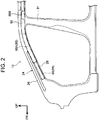
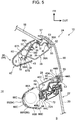
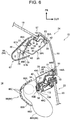
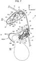
- a first aspect of the invention provides a curtain airbag device mounting structure including: a first pillar that forms a part of a front pillar and extends substantially along a vehicle height direction; a second pillar that forms another part of the front pillar, the second pillar being disposed on a rear side of a vehicle relative to the first pillar at a predetermined distance from the first pillar and extending substantially along the vehicle height direction; a transparent member that is bridged between the first pillar and the second pillar and enables an outside of the vehicle to be viewed from a driver seat; and a curtain airbag device including a curtain airbag stored along a roof side rail and the second pillar, the curtain airbag being configured to be supplied with gas to inflate and deploy in a curtain-like fashion over a side portion of a cabin of the vehicle in case of a collision of the vehicle.
- the first pillar that forms a part of the A-pillar and is provided so as to extend substantially along the vehicle height direction, and a second pillar that forms another part of the A-pillar is disposed on the rear side of the vehicle relative to the first pillar at a predetermined distance from the first pillar and is provided so as to extend substantially along the vehicle height direction are provided. Therefore, a driver can view an object on the other side of the A-pillar from the transparent member bridged between the first pillar and the second pillar.
- the curtain airbag configured such that in case of a collision of the vehicle, the curtain airbag can be supplied with a gas to inflate and deploy in a curtain-like fashion over a side portion of the vehicle cabin is stored along the roof side rail and the second pillar.
- the curtain airbag is stored in a part of the A-pillar, the part being in the vicinity of a door opening, and in case of a collision of the vehicle, the curtain airbag can quickly be inflated and deployed over a side of an occupant and thereby hold the occupant.
- the curtain airbag is stored along the first pillar, when the curtain airbag inflates and deploys, the second pillar located on the vehicle rear side of the first pillar may hinder the inflation and deployment of the curtain airbag because the curtain airbag inflates and deploys in a curtain-like fashion over a side portion of the vehicle cabin.
- the curtain airbag is stored along the second pillar, and thus, the curtain airbag can smoothly inflate and deploy without being hindered by the second pillar.
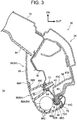
- the curtain airbag device may include a front pillar garnish attached to a vehicle interior side of the front pillar.
- the front pillar garnish may include a front-side garnish attached to the first pillar and a rear-side garnish formed separately from the front-side garnish and attached to the second pillar, the rear-side garnish being configured to cover the curtain airbag from a vehicle interior side of the curtain airbag and to hold the curtain airbag in a state in which the curtain airbag is apart from the second pillar.
- the A-pillar garnish is attached to the vehicle interior side of the A-pillar.
- the A-pillar garnish includes the front-side garnish attached to the first pillar, and the rear-side garnish formed separately from the front-side garnish and attached to the second pillar.
- the rear-side garnish is configured so as to cover the curtain airbag from the vehicle interior side and hold the curtain airbag in a state in which the curtain airbag is apart from the second pillar. Therefore, when the curtain airbag inflates and deploys, a deployment load of the curtain airbag is transferred only to the rear-side garnish and the deployment load causes the rear-side garnish to move apart from the second pillar and be held.
- the curtain airbag can smoothly be inflated and deployed in the vehicle cabin from between the second pillar and the rear-side garnish while breakage caused as a result of applying the deployment load locally to the A-pillar garnish and flying of the A-pillar garnish in the vehicle cabin are prevented.
- the above configuration has an effect of enabling enhancement of the capability of deployment of the curtain airbag.
- the rear-side garnish may be attached to the second pillar via a tether clip.
- the rear-side garnish is attached to the second pillar via a tether clip, and thus, flying of the rear-side garnish when the rear-side garnish moves apart from the second pillar as a result of inflation and deployment of the curtain airbag can be suppressed by the tether clip.
- the above configuration has an excellent effect of enabling suppression of flying of the rear-side garnish, and thus, the A-pillar garnish during deployment of the curtain airbag.
- the front-side garnish may include an extension portion at an upper end portion of the front-side garnish in the vehicle height direction, the extension portion extending toward the rear side of the vehicle, and including a rear end portion covered by an upper end portion of the rear-side garnish in the vehicle height direction; and the tether clip may be attached to the extension portion at a position corresponding to the extension portion in the rear-side garnish.
- the extension portion is provided at the upper end portion of the front-side garnish, the extension portion is provided so as to extend toward the rear side of the vehicle and the rear end portion is covered by the upper end portion of the rear-side garnish.
- the vehicle upper side of the space between the front-side garnish and the rear-side garnish has an outer appearance that is continuous with the front-side garnish and the rear end portion of the extension portion is covered by the rear-side garnish, enabling a terminal end to be unnoticeable to occupants and provision of a neat appearance.
- the tether clip is provided at a position in the rear-side garnish, the position corresponding to the extension portion of the front-side garnish, floating-up of the rear-side garnish at the part in which the extension portion of the front-side garnish and the rear-side garnish are laid on each other can be suppressed.
- each of the front-side garnish and the rear-side garnish may have a U-shape in a section orthogonal to a longitudinal direction of the front pillar and at least one of a wire harness and a hose may be held between the front-side garnish and the first pillar, and a part of the curtain airbag device may be stored between the rear-side garnish and the second pillar.
- each of the front-side garnish and the rear-side garnish has a substantially U-shape in a section orthogonal to the longitudinal direction of the A-pillar. Then, at least either of a wire harness and a hose is held between the front-side garnish and the first pillar, and a part of the curtain airbag device is stored between the rear-side garnish and the second pillar.
- a wire harness and a hose can efficiently be stored in the limited space between the A-pillar and the A-pillar garnish without hindering inflation and deployment of the curtain airbag.
- the above configuration has an excellent effect of enabling enhancement in storage space efficiency.
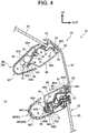
- the second pillar may include a reaction force surface at a part on a vehicle interior side of the second pillar, the part facing the curtain airbag, a thickness direction of the reaction force surface being substantially along a vehicle width direction.
- the reaction force surface the thickness direction of which is substantially the width direction of the vehicle, is provided at the part on the vehicle interior side of the second pillar, the part facing the curtain airbag.
- the reaction force surface is provided in the vicinity of the curtain airbag. Therefore, when the curtain airbag inflates and deploys, the curtain airbag can promptly receive a reaction force of the deployment from the reaction force surface, enabling the curtain airbag to be quickly deployed toward the inner side substantially in the width direction of the vehicle, that is, the inner side of the vehicle cabin.
- the above configuration has an excellent effect of enabling further enhancement in capability of deployment of the curtain airbag.
- the second pillar may include: a pillar inner panel that forms a part of the second pillar and has a L-shape in a section orthogonal to a longitudinal direction, the L-shape being formed by the reaction force surface and a extending surface, the extending surface extending outward in the vehicle width direction from the reaction force surface; and a pillar outer panel that forms another part of the second pillar, an end surface of at least one of end portions of the pillar inner panel in a direction orthogonal to a longitudinal direction of the pillar inner panel being in contact with a surface of an end portion of the pillar outer panel in a direction orthogonal to a longitudinal direction of the pillar outer panel.
- the pillar inner panel that forms a part of the second pillar and has a L-shape in a section orthogonal to the longitudinal direction, the L-shape being formed by the reaction force surface and the surface provided so as to extend from the reaction force surface toward the outer side in the width direction of the vehicle, and an end surface of at least one of end portions in the direction orthogonal to the longitudinal direction abuts on a surface of an end portion in the direction orthogonal to the longitudinal direction of the pillar outer panel that forms the other part of the second pillar.
- the need for a flange for joining the pillar outer panel and the pillar inner panel, the flange projecting to the outside of the A-pillar, is eliminated at least for one of end portions in the direction orthogonal to the longitudinal direction of the second pillar of the A-pillar.
- the above configuration has an excellent effect of enabling securing wider view during driving of the vehicle.
- a part of the second pillar, the part facing the curtain airbag may include a substantially flat surface.
- the part of the second pillar, the part facing the curtain airbag includes a substantially flat surface, and thus, storage space efficiency of the accommodation space for the curtain airbag, the accommodation space being formed by the second pillar and the A-pillar garnish, can be enhanced.
- the above configuration has an excellent effect of enabling enhancement in mountability of the curtain airbag.
- a second aspect which is not part of the present invention provides a curtain airbag deployment method.
- the curtain airbag deployment method according to the second aspect is performable by a structure mounting a curtain airbag device including a rear-side garnish that forms a part of a front pillar garnish and has a U-shape that opens to a front pillar side in a section orthogonal to a longitudinal direction, the U-shape being formed by a first side wall portion and a second side wall portion facing the first side wall portion, a curtain airbag stored in a folded state between the rear-side garnish and a pillar inner panel, and an inflator that activates to supply a gas to the curtain airbag upon detection or prediction of a collision of a relevant vehicle.
- the curtain airbag deployment method includes: holding the rear-side garnish in a state in which the rear-side garnish is apart from the front pillar via initial inflation of the curtain airbag caused by the activation of the inflator; after the initial inflation, causing the curtain airbag to inflate and deploy from a gap between the rear-side garnish and the front pillar while pressing the first side wall portion and the second side wall portion of the rear-side garnish apart from each other; and after causing the curtain airbag to inflate and deploy from a gap between the rear-side garnish and the front pillar, inflating and deploying the curtain airbag toward an inner side of an interior of the vehicle from between the first side wall portion and the second side wall portion pressed apart from each other to inflate and deploy the curtain airbag in a curtain-like fashion over a side portion of the interior of the vehicle while withdrawing the rear-side garnish.
- the rear-side garnish upon activation of the inflator, the rear-side garnish is held in a state in which the rear-side garnish is apart way from the A-pillar via initial inflation of the curtain airbag. Then, the curtain airbag inflates and deploys from the gap between the rear-side garnish and the A-pillar while pressing the first side wall portion and the second side wall portion of the rear-side garnish apart from each other. Then, the curtain airbag is inflated and deployed toward the inner side of the vehicle cabin from between the first side wall portion and the second side wall portion pressed apart from each other to inflate and deploy in a curtain-like fashion over a side portion of the vehicle cabin while withdrawing the rear-side garnish.
- the curtain airbag can be inflated and deployed in a curtain-like fashion over a side portion of the cabin of the vehicle.
- the above configuration has an excellent effect of enabling ensuring both wide view during driving of the vehicle and capability of deployment of the curtain airbag.
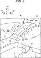
- Arrow FR indicated in each drawing denotes the front side in a front-rear direction of a vehicle
- arrow OUT denotes the outer side in a width direction of the vehicle
- arrow UP denotes the upper side in a vehicle height direction.
- a left-right pair of vehicle seats 16 are arranged, and a not-illustrated driver can sit on one of the vehicle seats 16.
- the vehicle 12 in the present embodiment is a left-hand drive vehicle, and in the figure, illustration of the vehicle seat 16 on the driver's seat side is omitted.
- a front windshield (hereinafter simply referred to as "front windshield”) 18 is provided on the vehicle front side relative to the vehicle seat 16, a front windshield (hereinafter simply referred to as "front windshield”) 18 is provided.
- the front windshield 18 is a transparent window member that separates the inside of the cabin 14 and the outside of the cabin 14 from each other, and has a thickness substantially in the front-rear direction of the vehicle, and is further inclined toward the rear side of the vehicle further on the upper side of the vehicle in side view.
- An upper end portion of the front windshield 18 is connected to a front header (not illustrated) forming a front end portion of a roof including a roof panel 19 (see FIG. 3 ).
- a lower end portion of the front windshield 18 is disposed so as to face, in the front-rear direction of the vehicle, a rear end portion of a hood that covers a power unit room provided on the front side of the vehicle from the upper side of the vehicle, and is connected to a cowl extending in the width direction of the vehicle (neither of both the hood and the cowl illustrated).
- the front windshield 18 is formed so as to have a constant thickness, and has a gently curved shape such that an intermediate part, in the width direction of the vehicle, of the front windshield 18 projects toward the front side of the vehicle.
- Paired left and right A-pillars 24 are provided on respective outer sides, in the width direction of the vehicle, of the front windshield 18 and the front sides of respective front doors 22 each including a front side window 20.
- the paired left and right A-pillars 24 each extend along a relevant end portion, in the width direction of the vehicle, of the front windshield 18, substantially with the vehicle height direction as a longitudinal direction thereof. In other words, the paired left and right A-pillars 24 are inclined toward the rear side of the vehicle further on the upper side of the vehicle.
- description of the A-pillar 24 on the front passenger seat side will be provided; however, the A-pillar 24 on the opposite side of the front passenger seat (driver's seat) has a configuration that is similar to that of the A-pillar 24 on the front passenger seat side.
- the A-pillar 24 includes a first pillar 26 and a second pillar 28.
- the first pillar 26 extends substantially along the vehicle height direction, and an end portion 30, in the width direction of the vehicle, of the front windshield 18 is joined to the first pillar 26 via a urethane adhesive 32 and a cushion rubber 34.
- the first pillar 26 includes a first pillar inner panel 36 made of a steel plate, which serves as a pillar inner panel, and a first pillar outer panel 38 made of a steel plate, which serves as a pillar outer panel.
- the first pillar inner panel 36 has a substantially crank-like shape in a section orthogonal to a longitudinal direction (direction substantially along the vehicle height direction).
- the first pillar outer panel 38 has a substantially U-shape that opens toward the inner side substantially in the width direction of the vehicle in a section orthogonal to a longitudinal direction (direction substantially along the vehicle height direction).
- the first pillar outer panel 38 forms a closed section jointly with the first pillar inner panel 36.
- the first pillar inner panel 36 is provided on the front side, substantially in the front-rear direction of the vehicle, of the first pillar outer panel 38 so as to face the first pillar outer panel 38, and the first pillar outer panel 38 and the first pillar inner panel 36 are joined to each other via weld portions 39.
- respective end portions 36A, 36B in a lateral direction of the first pillar inner panel 36 is laid on and welded to respective flat surfaces 42, 43, which are flat surfaces in an in-plane direction of the first pillar outer panel 38.
- the second pillar 28 is disposed substantially on the rear side of the vehicle relative to the first pillar 26. More specifically, the second pillar 28 is disposed at a predetermined distance from the first pillar 26 substantially in the front-rear direction of the vehicle.
- the predetermined distance is set to be equal to or longer than the distance between the centers of the pupils of a driver sat on the vehicle seat 16.
- the "distance between the centers of the pupils” refers to the distance between the center of the pupil of the right eye (not illustrated) and the center of the pupil of the left eye (not illustrated) of a driver, and for example, approximately 60 to 65 mm in Japanese adults.
- the predetermined distance is set as 65 mm.
- the second pillar 28 extends substantially in parallel to the first pillar 26 (substantially along the vehicle height direction), and includes a second pillar inner panel 40 made of a steel plate, which serves as a pillar inner panel, and a second pillar outer panel 44 made of a steel plate, which serves as a pillar outer panel.
- the second pillar inner panel 40 has a substantially L-shape in a section orthogonal to a longitudinal direction (substantially along the vehicle height direction).
- the second pillar outer panel 44 has a substantially crank-like shape in a section orthogonal to a longitudinal direction (substantially along the vehicle height direction).
- the second pillar outer panel 44 forms a closed section jointly with the second pillar inner panel 40.
- the second pillar inner panel 40 is provided substantially on the front side of the second pillar outer panel 44 so as to face the second pillar outer panel 44, and the second pillar outer panel 44 and the second pillar inner panel 40 are joined to each other via weld portions 51.
- an end portion 40A in a lateral direction (direction orthogonal to the longitudinal direction) of the second pillar inner panel 40 is abutted on and welded to a flat surface 52, which is a flat surface in an in-plane direction of an end portion 44A in a lateral direction (direction orthogonal to the longitudinal direction) of the second pillar outer panel 44. Consequently, an outer surface 56 of the end portion 40A of the second pillar inner panel 40 and an end surface 44B of the end portion 44A in the lateral direction of the second pillar outer panel 44 are disposed so as to be substantially flush with each other.
- an end portion 44C in a lateral direction of the second pillar outer panel 44 is laid on and welded to a flat wall 54, which is a flat surface of the second pillar inner panel 40 and serves as a reaction force surface.
- the flat wall 54 is provided so as to extend substantially with the width direction of the vehicle as a thickness direction thereof.
- An opening trim 72 is attached to a part in which the end portion 40B in the lateral direction of the second pillar inner panel 40 and the end portion 44C in the lateral direction of the second pillar outer panel 44 are in abutment with each other, that is, a flange 58.
- the opening trim 72 is positioned at a position at which the opening trim 72 is in abutment with the second pillar outer panel 44.
- a seal member of the front door 22 can be brought into abutment with the second pillar outer panel 44.
- a width dimension of each of the first pillar 26 and the second pillar 28 substantially in a horizontal direction as viewed from an eye point (not illustrated) of a driver is set to be equal to or smaller than the distance between the centers of the pupils of the driver.
- An A-pillar outer glass member 50 is bridged between the first pillar 26 and the second pillar 28 from the outer side substantially in the width direction of the vehicle via urethane adhesives 53 and cushion rubbers 55.
- the A-pillar outer glass member 50 is a transparent window member substantially with the width direction of the vehicle as a thickness direction thereof, and is inclined toward the rear side of the vehicle further on the upper side of the vehicle in side view (see FIG. 1 ).
- a seal member 57 is provided between the A-pillar outer glass member 50 and the front windshield 18, and the seal member 57 suppresses entry of, e.g., rain water into between the A-pillar outer glass member 50 and the front windshield 18.
- the A-pillar outer glass member 50 is not limited to one made of glass and may be formed of, e.g., a transparent fiber-reinforced resin.
- An A-pillar garnish 64 is provided on the inner sides, in the width direction of the vehicle, of the first pillar 26 and the second pillar 28.
- the A-pillar garnish 64 which is made of a resin, and includes a front-side garnish 66 provided on the vehicle cabin side of the first pillar 26, and a rear-side garnish 86 provided on the vehicle cabin side of the second pillar 28.
- the front-side garnish 66 includes a body portion 67 provided so as to extend substantially in the vehicle height direction along the first pillar 26 illustrated in FIG. 4 , and an extension portion 69 provided at an upper end portion of the body portion 67 so as to extend substantially toward the rear side of the vehicle.
- a plurality of clip seats 66A and clips 65 attached to the clip seats 66A are provided along a longitudinal direction so as to be spaced from each other.
- the clip seats 66A are provided so as to face a wall portion 36D on the inner side, substantially in the width direction of the vehicle, of the first pillar inner panel 36.
- the front-side garnishes 66 are attached to the first pillar 26.
- an end portion, on the lower side of the vehicle, of the body portion 67 is inserted in a not-illustrated slot formed in an instrumental panel 73, which is illustrated in FIG. 1 (see FIG. 1 ).
- the body portion 67 of the front-side garnish 66 has a substantially U-shape that opens toward the outer side substantially in the width direction of the vehicle, in a section orthogonal to the longitudinal direction of the body portion 67, the substantially U-shape being formed by a first side wall portion 67A covering the first pillar inner panel 36 from the front side of the vehicle and a second side wall portion 67B facing the first side wall portion 67A.
- An accommodation space S is formed between the first side wall portion 67A and the first pillar inner panel 36, and wire harnesses 78 and a hose 80 are held in the accommodation space S.
- the second side wall portion 67B is spaced from a surface 38A, on the rear side of the vehicle, of the first pillar outer panel 38 and is provided so as to be substantially flush with the vehicle rear side surface 38A.
- the extension portion 69 of the front-side garnish 66 is formed integrally with the body portion 67, and an end portion, on the upper side of the vehicle, of the extension portion 69 is in abutment with a roof head liner 84.
- a step portion 69B provided so as to extend on the outer side substantially in the width direction of the vehicle relative to a general wall portion of the extension portion 69 is formed at the rear end portion 69A of the extension portion 69.
- An upper end portion of the rear-side garnish 86 is in abutment with the step portion 69B so as to be laid on the step portion 69B, whereby in a surface on the inner side, in the width direction of the vehicle, of the general wall portion of the extension portion 69 and a surface on the inner side, in the width direction of the vehicle, of the upper end portion of the rear-side garnish 86 are disposed so as to be substantially flush with each other.
- the rear-side garnish 86 is provided so as to extend substantially in the vehicle height direction along the second pillar 28. As illustrated in FIG. 3 , the rear-side garnish 86 has a substantially U-shape that opens toward the outer side substantially in the width direction of the vehicle in a section orthogonal to a longitudinal direction, the substantially U-shape being formed by a first side wall portion 86A provided so as to extend substantially in the width direction of the vehicle and a second side wall portion 86B facing the first side wall portion 86A.
- the first side wall portion 86A is spaced from a surface 40C, on the front side of the vehicle, of the second pillar inner panel 40 of the second pillar 28 and is provided so as to be substantially flush with the vehicle front side surface 40C.
- the second side wall portion 86B is provided so as to be extend over the vehicle rear side of the flange 58 and the outer side, in the width direction of the vehicle, of the flange 58 and is arranged such that an end portion 86D in the width direction of the vehicle is laid on a lip portion 72A of the opening trim 72 in the front-rear direction of the vehicle. Furthermore, a plurality of ribs 86C projecting to the outer side substantially in the width direction of the vehicle along a thickness direction are formed at a part between the first side wall portion 86A and the second side wall portion 86B of the rear-side garnish 86.
- a clip seat 86E and a tether clip 71 attached to the clip seat 86E are provided at a surface on the outer side in the width direction of the vehicle (back surface) of the rear-side garnish 86. More specifically, the clip seat 86E and the tether clip 71 are provided at a part of the rear-side garnish 86, the part corresponding to the extension portion 69 of the front-side garnish 66.
- a basic configuration of the tether clip 71 is substantially similar to configurations known through, for example, Japanese Patent Application Publication No. 2015-202783 , etc., and thus, detailed description thereof will be omitted.
- a clip seat 66A and a clip 65 attached to the clip seat 66A each having a configuration that is similar to that of the front-side garnish 66 is provided at a substantially intermediate portion in a longitudinal direction of the rear-side garnish 86 (not illustrated).
- the tether clip 71 attached to the clip seat 86E provided in the rear-side garnish 86 is inserted in a through-hole formed so as to extend through the first pillar inner panel 36 in a thickness direction, the first pillar inner panel 36 being joined to the flat wall 54 of the second pillar inner panel 40 from the inner side in the width direction of the vehicle.
- the clip 65 attached to the clip seat 66A is inserted in a through-hole formed so as to extend through the flat wall 54 of the second pillar inner panel 40 in a thickness direction.
- the rear-side garnish 86 is attached to the second pillar 28.
- an end portion, on the lower side of the vehicle, of the rear-side garnish 86 is inserted in the not-illustrated slot formed in the instrumental panel 73 illustrated in FIG. 1 (see FIG. 1 ).
- a curtain airbag device 88 includes a curtain airbag 88A, a tension strap 96 (see FIG. 2 ) and an inflator 88B.
- the curtain airbag 88A is formed so as to, upon supply of a gas from the inflator 88B, inflate and deploy along a side portion of the vehicle cabin and cover the front side window 20 (see FIG. 4 ) and a B-pillar (center pillar) 91 (see FIG. 2 ).
- the curtain airbag 88A is folded in an elongated shape and stored together with the inflator 88B in a roof side rail 92 provided at an upper end portion of the side portion of the vehicle cabin.
- the curtain airbag 88A folded in the elongated shape extends from a substantially intermediate portion in a longitudinal direction of the second pillar 28 in the A-pillar 24 to the upper end side of a not-illustrated C-pillar (rear pillar) along the roof side rail 92.
- a basic configuration of the curtain airbag 88A is substantially similar to configurations known through, for example, Japanese Patent Application No. 2012-40963 , etc., and detailed description thereof will be omitted.
- the curtain airbag 88A arranged along the second pillar 28 is accommodated in an accommodation space S formed by the rear-side garnish 86 and the second pillar 28, in abutment with distal end portions of the ribs 86C of the rear-side garnish 86.
- the tension strap 96 is provided on the vehicle front side of the curtain airbag 88A.
- the tension strap 96 is provided so as to extend along the second pillar 28, and an end portion, on the front side of the vehicle, of the tension strap 96 is attached to an end portion, on the front side of the vehicle, of the second pillar 28 (see FIG. 2 ).
- the controller Upon detection of a collision of the vehicle by a not-illustrated airbag sensor and output of a collision signal to a not-illustrated controller, the controller applies a predetermined current to the inflator 88B if the controller determines such current application as necessary based on the input collision signal. Consequently, as illustrated in FIG. 5 , the inflator 88B activates and a gas thereby flows into the curtain airbag 88A in the folded state.
- initial inflation of the curtain airbag 88A causes the curtain airbag 88A to receive a reaction force from the flat wall 54 and transfers a deployment load to the rear-side garnish 86, and thus the rear-side garnish 86 is moved apart from the second pillar 28 and held within a range allowed by the tether clip 71.
- the inflating and deploying curtain airbag 88A causes the first side wall portion 86A and the second side wall portion 86B of the rear-side garnish 86 to be pressed apart in a direction in which the first side wall portion 86A and the second side wall portion 86B move apart from each other.
- the curtain airbag 88A inflates and deploys toward the inner side of the vehicle cabin from the gap between the rear-side garnish 86 and the A-pillar 24. Then, as illustrated in FIG. 7 , the curtain airbag 88A inflates and deploys in a curtain-like fashion over a side of the vehicle cabin while slightly turning and thereby withdrawing the rear-side garnish 86 substantially toward the front side of the vehicle.
- the curtain airbag 88A can be inflated and deployed in a curtain-like fashion over a side portion of the vehicle cabin.
- the curtain airbag 88A configured so as to be able to inflate and deploy in a curtain-like fashion over a side portion of the vehicle cabin when the curtain airbag 88A is supplied with a gas in case of a collision of the vehicle is stored along the roof side rail 92 and the second pillar 28.
- the curtain airbag 88A is stored in a part of the A-pillar 24, the part being in the vicinity of a door opening, and thus, in case of a collision of the vehicle, the curtain airbag 88A can quickly be inflated and deployed over a side of an occupant and thereby hold the occupant.
- the curtain airbag 88A is stored along the first pillar 26, when the curtain airbag 88A inflates and deploys, the second pillar 28 located on the vehicle rear side of the first pillar 26 may hinder the inflation and deployment of the curtain airbag 88A because the curtain airbag 88A inflates and deploys in a curtain-like fashion over a side portion of the vehicle cabin.
- the curtain airbag 88A is stored along the second pillar 28, and thus, the curtain airbag 88A can smoothly inflate and deploy without being hindered by the second pillar 28. Consequently, both wide view during driving of the vehicle and capability of deployment of the curtain airbag 88A can be ensured.
- the A-pillar garnish 64 is attached to the vehicle cabin side of the A-pillar 24.
- the A-pillar garnish 64 includes the front-side garnish 66 attached to the first pillar 26, and the rear-side garnish 86 formed separately from the front-side garnish 66 and attached to the second pillar 28.
- the rear-side garnish 86 is configured so as to be able to cover the curtain airbag 88A from the vehicle cabin side and move apart from the second pillar 28. Therefore, when the curtain airbag 88A inflates and deploys, a deployment load of the curtain airbag 88A is transferred only to the rear-side garnish 86 and the deployment load causes the rear-side garnish 86 to move apart from the second pillar 28 (see FIG. 5 ).
- the curtain airbag 88A can be inflated and deployed in the vehicle cabin 14 from between the second pillar 28 and the rear-side garnish 86 while breakage caused as a result of applying the deployment load locally to the A-pillar garnish 64 is prevented (see FIGS. 6 and 7 ). Consequently, the capability of deployment of the curtain airbag 88A can be enhanced.
- the extension portion 69 is provided at the upper end portion of the front-side garnish 66, the extension portion 69 is provided so as to extend substantially toward the rear side of the vehicle and the rear end portion 69A is covered by the upper end portion of the rear-side garnish 86 (see also FIG. 3 ).
- the vehicle upper side of the space between the front-side garnish 66 and the rear-side garnish 86 has an outer appearance that is continuous with the front-side garnish 66 and the rear end portion 69A of the extension portion 69 is covered by the rear-side garnish 86, enabling a terminal end of the rear end portion 69A to be unnoticeable to occupants and provision of a neat appearance.
- the tether clip 71 is provided at a position in the rear-side garnish 86, the position corresponding to the extension portion 69 of the front-side garnish 66, floating-up of the rear-side garnish 86 at the part in which the extension portion 69 of the front-side garnish 66 and the rear-side garnish 86 are laid on each other can be suppressed. Consequently, a quality in outer appearance of the A-pillar garnish 64 can be enhanced.
- each of the front-side garnish 66 and the rear-side garnish 86 has a substantially U-shape in a section orthogonal to the longitudinal direction of the A-pillar 24. Then, the wire harnesses 78 and the hose 80 are held between the front-side garnish 66 and the first pillar 26, and a part of the curtain airbag 88A is stored between the rear-side garnish 86 and the second pillar 28. In other words, the wire harnesses 78 and the hose 80 can efficiently be stored in the limited space between the A-pillar 24 and the A-pillar garnish 64 without hindering inflation and deployment of the curtain airbag 88A. Consequently, storage space efficiency can be enhanced.
- the flat wall 54 is provided at a part on the vehicle cabin side of the second pillar 28, the part facing the curtain airbag 88A.
- the flat wall 54 is provided in the vicinity of the curtain airbag 88A. Therefore, when the curtain airbag 88A inflates and deploys, the curtain airbag 88A promptly receives a reaction force of the deployment from the flat wall 54, enabling the curtain airbag 88A to be quickly deployed toward the inner side substantially in the width direction of the vehicle, that is, the inner side of the vehicle cabin. Consequently, the capability of deployment of the curtain airbag 88A can further be enhanced.
- the second pillar inner panel 40 that forms a part of the second pillar 28 and is formed so as to have a substantially L-shape in a section orthogonal to the longitudinal direction by the flat wall 54 and the vehicle front side surface 40C provided so as to extend from the flat wall 54 toward the outer side substantially in the width direction of the vehicle, an end surface of the end portion 40A in the direction orthogonal to the longitudinal direction is in abutment with the flat surface 52 of the end portion 44A in the direction orthogonal to the longitudinal direction of the second pillar outer panel 44 forming the other part of the second pillar 28.
- the flat wall 54 which is a part of the second pillar 28, the part facing the curtain airbag 88A, has a substantially flat surface, and thus, storage space efficiency of the accommodation space S for the curtain airbag 88A, the accommodation space S being formed by the second pillar 28 and the A-pillar garnish 64 can be enhanced. Consequently, mountability of the curtain airbag 88A can be enhanced.
- the wire harnesses 78 and the hose 80 are held between the front-side garnish 66 and the first pillar 26, only either of the wire harnesses 78 and the hose 80 may be held between the front-side garnish 66 and the first pillar 26.
- the second pillar inner panel 40 has a configuration in which the end surface of the end portion 40A in the direction orthogonal to the longitudinal direction is in abutment with the flat surface 52 of the second pillar outer panel 44 forming the other part of the second pillar 28, the present invention is not limited to this case, and may have a configuration in which the end portion 40B is in abutment with a surface of the second pillar outer panel 44 or a configuration in which each of the end portions 40A, 40B is in abutment with a surface of the second pillar outer panel 44.
Landscapes
- Engineering & Computer Science (AREA)
- Mechanical Engineering (AREA)
- Physics & Mathematics (AREA)
- Health & Medical Sciences (AREA)
- Life Sciences & Earth Sciences (AREA)
- Architecture (AREA)
- Chemical & Material Sciences (AREA)
- Structural Engineering (AREA)
- Civil Engineering (AREA)
- General Physics & Mathematics (AREA)
- Heart & Thoracic Surgery (AREA)
- Veterinary Medicine (AREA)
- General Engineering & Computer Science (AREA)
- Public Health (AREA)
- Biomedical Technology (AREA)
- General Health & Medical Sciences (AREA)
- Animal Behavior & Ethology (AREA)
- Molecular Biology (AREA)
- Medical Informatics (AREA)
- Pathology (AREA)
- Biophysics (AREA)
- Hematology (AREA)
- Surgery (AREA)
- Combustion & Propulsion (AREA)
- Electromagnetism (AREA)
- Transportation (AREA)
- Optics & Photonics (AREA)
- Fluid Mechanics (AREA)
- Thermal Sciences (AREA)
- Theoretical Computer Science (AREA)
- Dermatology (AREA)
- Organic Chemistry (AREA)
- Nonlinear Science (AREA)
- Vascular Medicine (AREA)
- Chemical Kinetics & Catalysis (AREA)
- Microelectronics & Electronic Packaging (AREA)
- Dispersion Chemistry (AREA)
- Crystallography & Structural Chemistry (AREA)
- Geology (AREA)
- Cardiology (AREA)
Description
- The present invention relates to a curtain airbag device mounting structure and a curtain airbag deployment method.
- Japanese Patent Application Publication No.
2006-273057 -
DE 10 2006 053990 discloses a curtain airbag device mounting structure according to the preamble of claim 1. - In general, a curtain airbag that in case of a collision of the relevant vehicle, inflates and deploys in a curtain-like fashion over a side portion of the vehicle cabin is partly stored in a space formed by an A-pillar inner panel and an A-pillar garnish, in a state before inflation and deployment. However, the vehicle pillar structure disclosed in
JP2006-273057 A - The present invention provides a curtain airbag device mounting structure that can ensure both wide view during driving of a vehicle and curtain airbag deployment capability.
- A first aspect of the invention provides a curtain airbag device mounting structure including: a first pillar that forms a part of a front pillar and extends substantially along a vehicle height direction; a second pillar that forms another part of the front pillar, the second pillar being disposed on a rear side of a vehicle relative to the first pillar at a predetermined distance from the first pillar and extending substantially along the vehicle height direction; a transparent member that is bridged between the first pillar and the second pillar and enables an outside of the vehicle to be viewed from a driver seat; and a curtain airbag device including a curtain airbag stored along a roof side rail and the second pillar, the curtain airbag being configured to be supplied with gas to inflate and deploy in a curtain-like fashion over a side portion of a cabin of the vehicle in case of a collision of the vehicle.
- According to the above aspect, the first pillar that forms a part of the A-pillar and is provided so as to extend substantially along the vehicle height direction, and a second pillar that forms another part of the A-pillar is disposed on the rear side of the vehicle relative to the first pillar at a predetermined distance from the first pillar and is provided so as to extend substantially along the vehicle height direction are provided. Therefore, a driver can view an object on the other side of the A-pillar from the transparent member bridged between the first pillar and the second pillar.
- Also, the curtain airbag configured such that in case of a collision of the vehicle, the curtain airbag can be supplied with a gas to inflate and deploy in a curtain-like fashion over a side portion of the vehicle cabin is stored along the roof side rail and the second pillar. In other words, the curtain airbag is stored in a part of the A-pillar, the part being in the vicinity of a door opening, and in case of a collision of the vehicle, the curtain airbag can quickly be inflated and deployed over a side of an occupant and thereby hold the occupant.
- Furthermore, as an example, if the curtain airbag is stored along the first pillar, when the curtain airbag inflates and deploys, the second pillar located on the vehicle rear side of the first pillar may hinder the inflation and deployment of the curtain airbag because the curtain airbag inflates and deploys in a curtain-like fashion over a side portion of the vehicle cabin. However, in the configuration according to the present invention, the curtain airbag is stored along the second pillar, and thus, the curtain airbag can smoothly inflate and deploy without being hindered by the second pillar.
- In other words, according to the above aspect, an excellent effect of enabling ensuring both wide view during driving of the vehicle and capability of deployment of the curtain airbag is provided.
- In the first aspect, the curtain airbag device may include a front pillar garnish attached to a vehicle interior side of the front pillar. The front pillar garnish may include a front-side garnish attached to the first pillar and a rear-side garnish formed separately from the front-side garnish and attached to the second pillar, the rear-side garnish being configured to cover the curtain airbag from a vehicle interior side of the curtain airbag and to hold the curtain airbag in a state in which the curtain airbag is apart from the second pillar.
- According to the above configuration, the A-pillar garnish is attached to the vehicle interior side of the A-pillar. The A-pillar garnish includes the front-side garnish attached to the first pillar, and the rear-side garnish formed separately from the front-side garnish and attached to the second pillar. Also, the rear-side garnish is configured so as to cover the curtain airbag from the vehicle interior side and hold the curtain airbag in a state in which the curtain airbag is apart from the second pillar. Therefore, when the curtain airbag inflates and deploys, a deployment load of the curtain airbag is transferred only to the rear-side garnish and the deployment load causes the rear-side garnish to move apart from the second pillar and be held. Thus, the curtain airbag can smoothly be inflated and deployed in the vehicle cabin from between the second pillar and the rear-side garnish while breakage caused as a result of applying the deployment load locally to the A-pillar garnish and flying of the A-pillar garnish in the vehicle cabin are prevented.
- In other words, the above configuration has an effect of enabling enhancement of the capability of deployment of the curtain airbag.
- In the first aspect, the rear-side garnish may be attached to the second pillar via a tether clip.
- According to the above configuration, the rear-side garnish is attached to the second pillar via a tether clip, and thus, flying of the rear-side garnish when the rear-side garnish moves apart from the second pillar as a result of inflation and deployment of the curtain airbag can be suppressed by the tether clip.
- In other words, the above configuration has an excellent effect of enabling suppression of flying of the rear-side garnish, and thus, the A-pillar garnish during deployment of the curtain airbag.
- In the first aspect, the front-side garnish may include an extension portion at an upper end portion of the front-side garnish in the vehicle height direction, the extension portion extending toward the rear side of the vehicle, and including a rear end portion covered by an upper end portion of the rear-side garnish in the vehicle height direction; and the tether clip may be attached to the extension portion at a position corresponding to the extension portion in the rear-side garnish.
- According to the above configuration, the extension portion is provided at the upper end portion of the front-side garnish, the extension portion is provided so as to extend toward the rear side of the vehicle and the rear end portion is covered by the upper end portion of the rear-side garnish. In other words, the vehicle upper side of the space between the front-side garnish and the rear-side garnish has an outer appearance that is continuous with the front-side garnish and the rear end portion of the extension portion is covered by the rear-side garnish, enabling a terminal end to be unnoticeable to occupants and provision of a neat appearance.
- Also, as the tether clip is provided at a position in the rear-side garnish, the position corresponding to the extension portion of the front-side garnish, floating-up of the rear-side garnish at the part in which the extension portion of the front-side garnish and the rear-side garnish are laid on each other can be suppressed.
- In the first aspect, each of the front-side garnish and the rear-side garnish may have a U-shape in a section orthogonal to a longitudinal direction of the front pillar and at least one of a wire harness and a hose may be held between the front-side garnish and the first pillar, and a part of the curtain airbag device may be stored between the rear-side garnish and the second pillar.
- According to the above configuration, each of the front-side garnish and the rear-side garnish has a substantially U-shape in a section orthogonal to the longitudinal direction of the A-pillar. Then, at least either of a wire harness and a hose is held between the front-side garnish and the first pillar, and a part of the curtain airbag device is stored between the rear-side garnish and the second pillar. In other words, a wire harness and a hose can efficiently be stored in the limited space between the A-pillar and the A-pillar garnish without hindering inflation and deployment of the curtain airbag.
- In other words, the above configuration has an excellent effect of enabling enhancement in storage space efficiency.
- In the first aspect, the second pillar may include a reaction force surface at a part on a vehicle interior side of the second pillar, the part facing the curtain airbag, a thickness direction of the reaction force surface being substantially along a vehicle width direction.
- According to the above configuration, the reaction force surface, the thickness direction of which is substantially the width direction of the vehicle, is provided at the part on the vehicle interior side of the second pillar, the part facing the curtain airbag. In other words, the reaction force surface is provided in the vicinity of the curtain airbag. Therefore, when the curtain airbag inflates and deploys, the curtain airbag can promptly receive a reaction force of the deployment from the reaction force surface, enabling the curtain airbag to be quickly deployed toward the inner side substantially in the width direction of the vehicle, that is, the inner side of the vehicle cabin.
- In other words, the above configuration has an excellent effect of enabling further enhancement in capability of deployment of the curtain airbag.
- In the first aspect, the second pillar may include: a pillar inner panel that forms a part of the second pillar and has a L-shape in a section orthogonal to a longitudinal direction, the L-shape being formed by the reaction force surface and a extending surface, the extending surface extending outward in the vehicle width direction from the reaction force surface; and a pillar outer panel that forms another part of the second pillar, an end surface of at least one of end portions of the pillar inner panel in a direction orthogonal to a longitudinal direction of the pillar inner panel being in contact with a surface of an end portion of the pillar outer panel in a direction orthogonal to a longitudinal direction of the pillar outer panel.
- According to the above configuration, the pillar inner panel that forms a part of the second pillar and has a L-shape in a section orthogonal to the longitudinal direction, the L-shape being formed by the reaction force surface and the surface provided so as to extend from the reaction force surface toward the outer side in the width direction of the vehicle, and an end surface of at least one of end portions in the direction orthogonal to the longitudinal direction abuts on a surface of an end portion in the direction orthogonal to the longitudinal direction of the pillar outer panel that forms the other part of the second pillar. Therefore, the need for a flange for joining the pillar outer panel and the pillar inner panel, the flange projecting to the outside of the A-pillar, is eliminated at least for one of end portions in the direction orthogonal to the longitudinal direction of the second pillar of the A-pillar.
- In other words, the above configuration has an excellent effect of enabling securing wider view during driving of the vehicle.
- In the first aspect, a part of the second pillar, the part facing the curtain airbag, may include a substantially flat surface.
- According to the above configuration, the part of the second pillar, the part facing the curtain airbag, includes a substantially flat surface, and thus, storage space efficiency of the accommodation space for the curtain airbag, the accommodation space being formed by the second pillar and the A-pillar garnish, can be enhanced.
- In other words, the above configuration has an excellent effect of enabling enhancement in mountability of the curtain airbag.
- A second aspect which is not part of the present invention provides a curtain airbag deployment method. The curtain airbag deployment method according to the second aspect is performable by a structure mounting a curtain airbag device including a rear-side garnish that forms a part of a front pillar garnish and has a U-shape that opens to a front pillar side in a section orthogonal to a longitudinal direction, the U-shape being formed by a first side wall portion and a second side wall portion facing the first side wall portion, a curtain airbag stored in a folded state between the rear-side garnish and a pillar inner panel, and an inflator that activates to supply a gas to the curtain airbag upon detection or prediction of a collision of a relevant vehicle. The curtain airbag deployment method includes: holding the rear-side garnish in a state in which the rear-side garnish is apart from the front pillar via initial inflation of the curtain airbag caused by the activation of the inflator; after the initial inflation, causing the curtain airbag to inflate and deploy from a gap between the rear-side garnish and the front pillar while pressing the first side wall portion and the second side wall portion of the rear-side garnish apart from each other; and after causing the curtain airbag to inflate and deploy from a gap between the rear-side garnish and the front pillar, inflating and deploying the curtain airbag toward an inner side of an interior of the vehicle from between the first side wall portion and the second side wall portion pressed apart from each other to inflate and deploy the curtain airbag in a curtain-like fashion over a side portion of the interior of the vehicle while withdrawing the rear-side garnish.
- According to the above configuration, upon activation of the inflator, the rear-side garnish is held in a state in which the rear-side garnish is apart way from the A-pillar via initial inflation of the curtain airbag. Then, the curtain airbag inflates and deploys from the gap between the rear-side garnish and the A-pillar while pressing the first side wall portion and the second side wall portion of the rear-side garnish apart from each other. Then, the curtain airbag is inflated and deployed toward the inner side of the vehicle cabin from between the first side wall portion and the second side wall portion pressed apart from each other to inflate and deploy in a curtain-like fashion over a side portion of the vehicle cabin while withdrawing the rear-side garnish. In other words, even where the rear-side garnish of the A-pillar garnish has a substantially U-shape in a section orthogonal to the longitudinal direction so as to cover the curtain airbag in a normal state, the curtain airbag can be inflated and deployed in a curtain-like fashion over a side portion of the cabin of the vehicle.
In other words, the above configuration has an excellent effect of enabling ensuring both wide view during driving of the vehicle and capability of deployment of the curtain airbag. - Features, advantages, and technical and industrial significance of exemplary embodiments of the invention will be described below with reference to the accompanying drawings, in which like numerals denote like elements, and wherein:
-
FIG. 1 is a schematic perspective diagram illustrating a cabin of a vehicle including a curtain airbag device mounting structure according to an embodiment; -
FIG. 2 is a side view illustrating a vehicle body frame of a vehicle including a curtain airbag device mounting structure according to an embodiment as viewed from the outer side in a width direction of the vehicle; -
FIG. 3 is an enlarged sectional view along line III-III ofFIG. 1 ; -
FIG. 4 is an enlarged sectional view along line IV-IV ofFIG. 1 ; -
FIG. 5 is an enlarged sectional view corresponding toFIG. 4 , the sectional view illustrating an initial state during inflation and deployment of a curtain airbag in a vehicle including a curtain airbag device mounting structure according to an embodiment; -
FIG. 6 is an enlarged sectional view corresponding toFIG. 4 , the sectional view illustrating an intermediate state during inflation and deployment of a curtain airbag in a vehicle including a curtain airbag device mounting structure according to an embodiment; and -
FIG. 7 is an enlarged sectional view corresponding toFIG. 4 , the sectional view illustrating a late state during inflation and deployment of a curtain airbag of a vehicle including a curtain airbag device mounting structure according to an embodiment. - An embodiment of a curtain airbag device mounting structure according to the present invention will be described below with reference to
FIGS. 1 to 7 . Arrow FR indicated in each drawing denotes the front side in a front-rear direction of a vehicle, arrow OUT denotes the outer side in a width direction of the vehicle, and arrow UP denotes the upper side in a vehicle height direction. - As illustrated in
FIG. 1 , on the front side of acabin 14 of avehicle 12 to which a curtain airbagdevice mounting structure 10 according to the present embodiment is applied, a left-right pair of vehicle seats 16 are arranged, and a not-illustrated driver can sit on one of the vehicle seats 16. Here, as an example, thevehicle 12 in the present embodiment is a left-hand drive vehicle, and in the figure, illustration of thevehicle seat 16 on the driver's seat side is omitted. - On the vehicle front side relative to the
vehicle seat 16, a front windshield (hereinafter simply referred to as "front windshield") 18 is provided. Thefront windshield 18 is a transparent window member that separates the inside of thecabin 14 and the outside of thecabin 14 from each other, and has a thickness substantially in the front-rear direction of the vehicle, and is further inclined toward the rear side of the vehicle further on the upper side of the vehicle in side view. An upper end portion of thefront windshield 18 is connected to a front header (not illustrated) forming a front end portion of a roof including a roof panel 19 (seeFIG. 3 ). Also, a lower end portion of thefront windshield 18 is disposed so as to face, in the front-rear direction of the vehicle, a rear end portion of a hood that covers a power unit room provided on the front side of the vehicle from the upper side of the vehicle, and is connected to a cowl extending in the width direction of the vehicle (neither of both the hood and the cowl illustrated). - The
front windshield 18 is formed so as to have a constant thickness, and has a gently curved shape such that an intermediate part, in the width direction of the vehicle, of thefront windshield 18 projects toward the front side of the vehicle. Paired left and right A-pillars 24 are provided on respective outer sides, in the width direction of the vehicle, of thefront windshield 18 and the front sides of respectivefront doors 22 each including afront side window 20. - The paired left and right A-pillars 24 each extend along a relevant end portion, in the width direction of the vehicle, of the
front windshield 18, substantially with the vehicle height direction as a longitudinal direction thereof. In other words, the paired left and right A-pillars 24 are inclined toward the rear side of the vehicle further on the upper side of the vehicle. Hereinafter, description of the A-pillar 24 on the front passenger seat side will be provided; however, the A-pillar 24 on the opposite side of the front passenger seat (driver's seat) has a configuration that is similar to that of the A-pillar 24 on the front passenger seat side. - As illustrated in
FIG. 4 , the A-pillar 24 includes afirst pillar 26 and asecond pillar 28. Thefirst pillar 26 extends substantially along the vehicle height direction, and an end portion 30, in the width direction of the vehicle, of thefront windshield 18 is joined to thefirst pillar 26 via aurethane adhesive 32 and acushion rubber 34. Thefirst pillar 26 includes a first pillarinner panel 36 made of a steel plate, which serves as a pillar inner panel, and a first pillarouter panel 38 made of a steel plate, which serves as a pillar outer panel. The first pillarinner panel 36 has a substantially crank-like shape in a section orthogonal to a longitudinal direction (direction substantially along the vehicle height direction). The first pillarouter panel 38 has a substantially U-shape that opens toward the inner side substantially in the width direction of the vehicle in a section orthogonal to a longitudinal direction (direction substantially along the vehicle height direction). The first pillarouter panel 38 forms a closed section jointly with the first pillarinner panel 36. In other words, the first pillarinner panel 36 is provided on the front side, substantially in the front-rear direction of the vehicle, of the first pillarouter panel 38 so as to face the first pillarouter panel 38, and the first pillarouter panel 38 and the first pillarinner panel 36 are joined to each other viaweld portions 39. - At the
weld portions 39,respective end portions inner panel 36 is laid on and welded to respectiveflat surfaces outer panel 38. - The
second pillar 28 is disposed substantially on the rear side of the vehicle relative to thefirst pillar 26. More specifically, thesecond pillar 28 is disposed at a predetermined distance from thefirst pillar 26 substantially in the front-rear direction of the vehicle. The predetermined distance is set to be equal to or longer than the distance between the centers of the pupils of a driver sat on thevehicle seat 16. Here, the "distance between the centers of the pupils" refers to the distance between the center of the pupil of the right eye (not illustrated) and the center of the pupil of the left eye (not illustrated) of a driver, and for example, approximately 60 to 65 mm in Japanese adults. In the present embodiment, as an example, the predetermined distance is set as 65 mm. - Also, the
second pillar 28 extends substantially in parallel to the first pillar 26 (substantially along the vehicle height direction), and includes a second pillarinner panel 40 made of a steel plate, which serves as a pillar inner panel, and a second pillarouter panel 44 made of a steel plate, which serves as a pillar outer panel. The second pillarinner panel 40 has a substantially L-shape in a section orthogonal to a longitudinal direction (substantially along the vehicle height direction). The second pillarouter panel 44 has a substantially crank-like shape in a section orthogonal to a longitudinal direction (substantially along the vehicle height direction). The second pillarouter panel 44 forms a closed section jointly with the second pillarinner panel 40. In other words, the second pillarinner panel 40 is provided substantially on the front side of the second pillarouter panel 44 so as to face the second pillarouter panel 44, and the second pillarouter panel 44 and the second pillarinner panel 40 are joined to each other viaweld portions 51. - At a
weld portion 51, anend portion 40A in a lateral direction (direction orthogonal to the longitudinal direction) of the second pillarinner panel 40 is abutted on and welded to aflat surface 52, which is a flat surface in an in-plane direction of anend portion 44A in a lateral direction (direction orthogonal to the longitudinal direction) of the second pillarouter panel 44. Consequently, anouter surface 56 of theend portion 40A of the second pillarinner panel 40 and anend surface 44B of theend portion 44A in the lateral direction of the second pillarouter panel 44 are disposed so as to be substantially flush with each other. Also, at aweld portion 51, anend portion 44C in a lateral direction of the second pillarouter panel 44 is laid on and welded to aflat wall 54, which is a flat surface of the second pillarinner panel 40 and serves as a reaction force surface. Theflat wall 54 is provided so as to extend substantially with the width direction of the vehicle as a thickness direction thereof. - An
opening trim 72 is attached to a part in which theend portion 40B in the lateral direction of the second pillarinner panel 40 and theend portion 44C in the lateral direction of the second pillarouter panel 44 are in abutment with each other, that is, aflange 58. Theopening trim 72 is positioned at a position at which theopening trim 72 is in abutment with the second pillarouter panel 44. Also, a seal member of thefront door 22 can be brought into abutment with the second pillarouter panel 44. Also, a width dimension of each of thefirst pillar 26 and thesecond pillar 28 substantially in a horizontal direction as viewed from an eye point (not illustrated) of a driver is set to be equal to or smaller than the distance between the centers of the pupils of the driver. - An A-pillar
outer glass member 50 is bridged between thefirst pillar 26 and thesecond pillar 28 from the outer side substantially in the width direction of the vehicle viaurethane adhesives 53 and cushionrubbers 55. The A-pillarouter glass member 50 is a transparent window member substantially with the width direction of the vehicle as a thickness direction thereof, and is inclined toward the rear side of the vehicle further on the upper side of the vehicle in side view (seeFIG. 1 ). Aseal member 57 is provided between the A-pillarouter glass member 50 and thefront windshield 18, and theseal member 57 suppresses entry of, e.g., rain water into between the A-pillarouter glass member 50 and thefront windshield 18. Also, the A-pillarouter glass member 50 is not limited to one made of glass and may be formed of, e.g., a transparent fiber-reinforced resin. - An
A-pillar garnish 64 is provided on the inner sides, in the width direction of the vehicle, of thefirst pillar 26 and thesecond pillar 28. TheA-pillar garnish 64, which is made of a resin, and includes a front-side garnish 66 provided on the vehicle cabin side of thefirst pillar 26, and a rear-side garnish 86 provided on the vehicle cabin side of thesecond pillar 28. - As illustrated in
FIG. 1 , the front-side garnish 66 includes abody portion 67 provided so as to extend substantially in the vehicle height direction along thefirst pillar 26 illustrated inFIG. 4 , and anextension portion 69 provided at an upper end portion of thebody portion 67 so as to extend substantially toward the rear side of the vehicle. As illustrated inFIG. 4 , at an outer side (back side), in the width direction of the vehicle, of thebody portion 67, a plurality ofclip seats 66A and clips 65 attached to the clip seats 66A are provided along a longitudinal direction so as to be spaced from each other. The clip seats 66A are provided so as to face awall portion 36D on the inner side, substantially in the width direction of the vehicle, of the first pillarinner panel 36. Then, as a result of theclips 65 attached to therespective clip seats 66A being inserted into through-holes 37 formed so as to extend through thewall portion 36D on the inner side substantially in the width direction of the vehicle, in a thickness direction, the front-side garnishes 66 are attached to thefirst pillar 26. Here, an end portion, on the lower side of the vehicle, of thebody portion 67 is inserted in a not-illustrated slot formed in aninstrumental panel 73, which is illustrated inFIG. 1 (seeFIG. 1 ). - The
body portion 67 of the front-side garnish 66 has a substantially U-shape that opens toward the outer side substantially in the width direction of the vehicle, in a section orthogonal to the longitudinal direction of thebody portion 67, the substantially U-shape being formed by a firstside wall portion 67A covering the first pillarinner panel 36 from the front side of the vehicle and a secondside wall portion 67B facing the firstside wall portion 67A. An accommodation space S is formed between the firstside wall portion 67A and the first pillarinner panel 36, and wire harnesses 78 and ahose 80 are held in the accommodation space S. Also, the secondside wall portion 67B is spaced from asurface 38A, on the rear side of the vehicle, of the first pillarouter panel 38 and is provided so as to be substantially flush with the vehiclerear side surface 38A. - As illustrated in
FIG. 1 , theextension portion 69 of the front-side garnish 66 is formed integrally with thebody portion 67, and an end portion, on the upper side of the vehicle, of theextension portion 69 is in abutment with aroof head liner 84. As illustrated inFIG. 3 , astep portion 69B provided so as to extend on the outer side substantially in the width direction of the vehicle relative to a general wall portion of theextension portion 69 is formed at therear end portion 69A of theextension portion 69. An upper end portion of the rear-side garnish 86 is in abutment with thestep portion 69B so as to be laid on thestep portion 69B, whereby in a surface on the inner side, in the width direction of the vehicle, of the general wall portion of theextension portion 69 and a surface on the inner side, in the width direction of the vehicle, of the upper end portion of the rear-side garnish 86 are disposed so as to be substantially flush with each other. - The rear-
side garnish 86 is provided so as to extend substantially in the vehicle height direction along thesecond pillar 28. As illustrated inFIG. 3 , the rear-side garnish 86 has a substantially U-shape that opens toward the outer side substantially in the width direction of the vehicle in a section orthogonal to a longitudinal direction, the substantially U-shape being formed by a firstside wall portion 86A provided so as to extend substantially in the width direction of the vehicle and a secondside wall portion 86B facing the firstside wall portion 86A. The firstside wall portion 86A is spaced from asurface 40C, on the front side of the vehicle, of the second pillarinner panel 40 of thesecond pillar 28 and is provided so as to be substantially flush with the vehiclefront side surface 40C. Also, the secondside wall portion 86B is provided so as to be extend over the vehicle rear side of theflange 58 and the outer side, in the width direction of the vehicle, of theflange 58 and is arranged such that anend portion 86D in the width direction of the vehicle is laid on alip portion 72A of theopening trim 72 in the front-rear direction of the vehicle. Furthermore, a plurality ofribs 86C projecting to the outer side substantially in the width direction of the vehicle along a thickness direction are formed at a part between the firstside wall portion 86A and the secondside wall portion 86B of the rear-side garnish 86. - As illustrated in
FIG. 3 , aclip seat 86E and atether clip 71 attached to theclip seat 86E are provided at a surface on the outer side in the width direction of the vehicle (back surface) of the rear-side garnish 86. More specifically, theclip seat 86E and thetether clip 71 are provided at a part of the rear-side garnish 86, the part corresponding to theextension portion 69 of the front-side garnish 66. A basic configuration of thetether clip 71 is substantially similar to configurations known through, for example, Japanese Patent Application Publication No.2015-202783 - Also, a
clip seat 66A and aclip 65 attached to theclip seat 66A (seeFIG. 4 ) each having a configuration that is similar to that of the front-side garnish 66 is provided at a substantially intermediate portion in a longitudinal direction of the rear-side garnish 86 (not illustrated). - The
tether clip 71 attached to theclip seat 86E provided in the rear-side garnish 86 is inserted in a through-hole formed so as to extend through the first pillarinner panel 36 in a thickness direction, the first pillarinner panel 36 being joined to theflat wall 54 of the second pillarinner panel 40 from the inner side in the width direction of the vehicle. Also, although not illustrated, other than thetether clip 71 attached to theclip seat 86E in the rear-side garnish 86, theclip 65 attached to theclip seat 66A is inserted in a through-hole formed so as to extend through theflat wall 54 of the second pillarinner panel 40 in a thickness direction. With the above configuration, the rear-side garnish 86 is attached to thesecond pillar 28. Here, as with the front-side garnish 66, an end portion, on the lower side of the vehicle, of the rear-side garnish 86 is inserted in the not-illustrated slot formed in theinstrumental panel 73 illustrated inFIG. 1 (seeFIG. 1 ). - A
curtain airbag device 88 includes acurtain airbag 88A, a tension strap 96 (seeFIG. 2 ) and an inflator 88B. Thecurtain airbag 88A is formed so as to, upon supply of a gas from the inflator 88B, inflate and deploy along a side portion of the vehicle cabin and cover the front side window 20 (seeFIG. 4 ) and a B-pillar (center pillar) 91 (seeFIG. 2 ). - In normal times, as illustrated in
FIG. 2 , thecurtain airbag 88A is folded in an elongated shape and stored together with the inflator 88B in aroof side rail 92 provided at an upper end portion of the side portion of the vehicle cabin. In the stored state, thecurtain airbag 88A folded in the elongated shape extends from a substantially intermediate portion in a longitudinal direction of thesecond pillar 28 in the A-pillar 24 to the upper end side of a not-illustrated C-pillar (rear pillar) along theroof side rail 92. A basic configuration of thecurtain airbag 88A is substantially similar to configurations known through, for example, Japanese Patent Application No.2012-40963 - As illustrated in
FIGS. 3 and4 , thecurtain airbag 88A arranged along thesecond pillar 28 is accommodated in an accommodation space S formed by the rear-side garnish 86 and thesecond pillar 28, in abutment with distal end portions of theribs 86C of the rear-side garnish 86. - Also, on the vehicle front side of the
curtain airbag 88A, thetension strap 96 is provided. Thetension strap 96 is provided so as to extend along thesecond pillar 28, and an end portion, on the front side of the vehicle, of thetension strap 96 is attached to an end portion, on the front side of the vehicle, of the second pillar 28 (seeFIG. 2 ). - Next, operation and effects of the present embodiment will be described.
- Upon detection of a collision of the vehicle by a not-illustrated airbag sensor and output of a collision signal to a not-illustrated controller, the controller applies a predetermined current to the inflator 88B if the controller determines such current application as necessary based on the input collision signal. Consequently, as illustrated in
FIG. 5 , the inflator 88B activates and a gas thereby flows into thecurtain airbag 88A in the folded state. As a result, initial inflation of thecurtain airbag 88A causes thecurtain airbag 88A to receive a reaction force from theflat wall 54 and transfers a deployment load to the rear-side garnish 86, and thus the rear-side garnish 86 is moved apart from thesecond pillar 28 and held within a range allowed by thetether clip 71. Concurrently, the inflating and deployingcurtain airbag 88A causes the firstside wall portion 86A and the secondside wall portion 86B of the rear-side garnish 86 to be pressed apart in a direction in which the firstside wall portion 86A and the secondside wall portion 86B move apart from each other. - As illustrated in
FIG. 6 , upon the firstside wall portion 86A and the secondside wall portion 86B of the rear-side garnish 86 moving apart from each other, thecurtain airbag 88A inflates and deploys toward the inner side of the vehicle cabin from the gap between the rear-side garnish 86 and the A-pillar 24. Then, as illustrated inFIG. 7 , thecurtain airbag 88A inflates and deploys in a curtain-like fashion over a side of the vehicle cabin while slightly turning and thereby withdrawing the rear-side garnish 86 substantially toward the front side of the vehicle. In other words, even where the rear-side garnish 86 of theA-pillar garnish 64 has a substantially U-shape in a section orthogonal to the longitudinal direction so as to cover thecurtain airbag 88A in a normal state, thecurtain airbag 88A can be inflated and deployed in a curtain-like fashion over a side portion of the vehicle cabin. - As described above, in the present embodiment, as illustrated in
FIG. 1 , thefirst pillar 26 that forms a part of the A-pillar 24 and is provided substantially along the vehicle height direction, and thesecond pillar 28 that forms the other part of the A-pillar 24, and is disposed on the rear side of the vehicle relative to thefirst pillar 26 at a predetermined distance from thefirst pillar 26 and is provided so as to extend substantially along the vehicle height direction. Therefore, a driver can view an object on the other side of the A-pillar 24, from between thefirst pillar 26 and thesecond pillar 28 via the A-pillarouter glass member 50. - Also, as illustrated in
FIG. 2 , thecurtain airbag 88A configured so as to be able to inflate and deploy in a curtain-like fashion over a side portion of the vehicle cabin when thecurtain airbag 88A is supplied with a gas in case of a collision of the vehicle is stored along theroof side rail 92 and thesecond pillar 28. In other words, thecurtain airbag 88A is stored in a part of the A-pillar 24, the part being in the vicinity of a door opening, and thus, in case of a collision of the vehicle, thecurtain airbag 88A can quickly be inflated and deployed over a side of an occupant and thereby hold the occupant. - Furthermore, as an example, if the
curtain airbag 88A is stored along thefirst pillar 26, when thecurtain airbag 88A inflates and deploys, thesecond pillar 28 located on the vehicle rear side of thefirst pillar 26 may hinder the inflation and deployment of thecurtain airbag 88A because thecurtain airbag 88A inflates and deploys in a curtain-like fashion over a side portion of the vehicle cabin. However, in the configuration of the present invention, thecurtain airbag 88A is stored along thesecond pillar 28, and thus, thecurtain airbag 88A can smoothly inflate and deploy without being hindered by thesecond pillar 28. Consequently, both wide view during driving of the vehicle and capability of deployment of thecurtain airbag 88A can be ensured. - Still furthermore, the
A-pillar garnish 64 is attached to the vehicle cabin side of the A-pillar 24. TheA-pillar garnish 64 includes the front-side garnish 66 attached to thefirst pillar 26, and the rear-side garnish 86 formed separately from the front-side garnish 66 and attached to thesecond pillar 28. Also, the rear-side garnish 86 is configured so as to be able to cover thecurtain airbag 88A from the vehicle cabin side and move apart from thesecond pillar 28. Therefore, when thecurtain airbag 88A inflates and deploys, a deployment load of thecurtain airbag 88A is transferred only to the rear-side garnish 86 and the deployment load causes the rear-side garnish 86 to move apart from the second pillar 28 (seeFIG. 5 ). Thus, thecurtain airbag 88A can be inflated and deployed in thevehicle cabin 14 from between thesecond pillar 28 and the rear-side garnish 86 while breakage caused as a result of applying the deployment load locally to theA-pillar garnish 64 is prevented (seeFIGS. 6 and7 ). Consequently, the capability of deployment of thecurtain airbag 88A can be enhanced. - Also, as illustrated in
FIG. 3 , since the rear-side garnish 86 is attached to thesecond pillar 28 via thetether clip 71, when the rear-side garnish 86 moves apart from thesecond pillar 28 as a result of inflation and deployment of thecurtain airbag 88A, the state in which the rear-side garnish 86 is apart from thesecond pillar 28 is held by thetether clip 71. Therefore, in case of deployment of thecurtain airbag 88A, flying of the rear-side garnish 86, and thus, theA-pillar garnish 64 inside thevehicle cabin 14 can be suppressed. - Furthermore, as illustrated in
FIG. 1 , theextension portion 69 is provided at the upper end portion of the front-side garnish 66, theextension portion 69 is provided so as to extend substantially toward the rear side of the vehicle and therear end portion 69A is covered by the upper end portion of the rear-side garnish 86 (see alsoFIG. 3 ). In other words, the vehicle upper side of the space between the front-side garnish 66 and the rear-side garnish 86 has an outer appearance that is continuous with the front-side garnish 66 and therear end portion 69A of theextension portion 69 is covered by the rear-side garnish 86, enabling a terminal end of therear end portion 69A to be unnoticeable to occupants and provision of a neat appearance. - Also, as illustrated in
FIG. 3 , thetether clip 71 is provided at a position in the rear-side garnish 86, the position corresponding to theextension portion 69 of the front-side garnish 66, floating-up of the rear-side garnish 86 at the part in which theextension portion 69 of the front-side garnish 66 and the rear-side garnish 86 are laid on each other can be suppressed. Consequently, a quality in outer appearance of theA-pillar garnish 64 can be enhanced. - Furthermore, as illustrated in
FIG. 4 , each of the front-side garnish 66 and the rear-side garnish 86 has a substantially U-shape in a section orthogonal to the longitudinal direction of the A-pillar 24. Then, the wire harnesses 78 and thehose 80 are held between the front-side garnish 66 and thefirst pillar 26, and a part of thecurtain airbag 88A is stored between the rear-side garnish 86 and thesecond pillar 28. In other words, the wire harnesses 78 and thehose 80 can efficiently be stored in the limited space between the A-pillar 24 and theA-pillar garnish 64 without hindering inflation and deployment of thecurtain airbag 88A. Consequently, storage space efficiency can be enhanced. - Still furthermore, the
flat wall 54, the thickness direction of which is substantially the vehicle width direction, is provided at a part on the vehicle cabin side of thesecond pillar 28, the part facing thecurtain airbag 88A. In other words, theflat wall 54 is provided in the vicinity of thecurtain airbag 88A. Therefore, when thecurtain airbag 88A inflates and deploys, thecurtain airbag 88A promptly receives a reaction force of the deployment from theflat wall 54, enabling thecurtain airbag 88A to be quickly deployed toward the inner side substantially in the width direction of the vehicle, that is, the inner side of the vehicle cabin. Consequently, the capability of deployment of thecurtain airbag 88A can further be enhanced. - Also, in the second pillar
inner panel 40 that forms a part of thesecond pillar 28 and is formed so as to have a substantially L-shape in a section orthogonal to the longitudinal direction by theflat wall 54 and the vehiclefront side surface 40C provided so as to extend from theflat wall 54 toward the outer side substantially in the width direction of the vehicle, an end surface of theend portion 40A in the direction orthogonal to the longitudinal direction is in abutment with theflat surface 52 of theend portion 44A in the direction orthogonal to the longitudinal direction of the second pillarouter panel 44 forming the other part of thesecond pillar 28. Therefore, the need for a flange for joining the second pillarouter panel 44 and the second pillarinner panel 40, the flange projecting to the outside of the A-pillar 24, is eliminated at least for one of end portions in the direction orthogonal to the longitudinal direction of thesecond pillar 28 of the A-pillar 24. Consequently, wider view during driving of the vehicle can be ensured. - Furthermore, as a result of the end surface of the
end portion 40A in the direction orthogonal to the longitudinal direction of the second pillarinner panel 40 being in abutment with theflat surface 52 of theend portion 44A in the direction orthogonal to the longitudinal direction of the second pillarouter panel 44 forming the other part of thesecond pillar 28, the need for a flange projecting toward the outside of the A-pillar 24 is eliminated. Consequently, the sectional area of the A-pillar 24 formed by the second pillarinner panel 40 and the second pillarouter panel 44 can be increased. Therefore, support stiffness of thecurtain airbag device 88 can be enhanced. - Still furthermore, the
flat wall 54, which is a part of thesecond pillar 28, the part facing thecurtain airbag 88A, has a substantially flat surface, and thus, storage space efficiency of the accommodation space S for thecurtain airbag 88A, the accommodation space S being formed by thesecond pillar 28 and theA-pillar garnish 64 can be enhanced. Consequently, mountability of thecurtain airbag 88A can be enhanced. - Although in the above-described embodiment, the wire harnesses 78 and the
hose 80 are held between the front-side garnish 66 and thefirst pillar 26, only either of the wire harnesses 78 and thehose 80 may be held between the front-side garnish 66 and thefirst pillar 26. - Although the second pillar
inner panel 40 has a configuration in which the end surface of theend portion 40A in the direction orthogonal to the longitudinal direction is in abutment with theflat surface 52 of the second pillarouter panel 44 forming the other part of thesecond pillar 28, the present invention is not limited to this case, and may have a configuration in which theend portion 40B is in abutment with a surface of the second pillarouter panel 44 or a configuration in which each of theend portions outer panel 44. - Although an embodiment of the present invention has been described above, it should be understood that: the present invention is not limited to the above embodiment; and various alterations other than the above are possible without departing from the scope of the present invention as defined in the appended claims.
Claims (6)
- A curtain airbag device mounting structure comprising:a first pillar (26) that forms a part of a front pillar (24) and extends substantially along a vehicle height direction;a second pillar (28) that forms another part of the front pillar (24), the second pillar (28) being disposed on a rear side of a vehicle relative to the first pillar (26) at a predetermined distance from the first pillar (26) and extending substantially along the vehicle height direction;a transparent member (50) that is bridged between the first pillar (26) and the second pillar (28) and enables an outside of the vehicle to be viewed from a driver seat; anda curtain airbag device (88) including a curtain airbag (88A) stored along a roof side rail (92) and the second pillar (28), the curtain airbag being configured to be supplied with gas to inflate and deploy in a curtain-like fashion over a side portion of a cabin of the vehicle in case of a collision of the vehicle, characterized in thata front pillar garnish (64) is attached to a vehicle interior side of the front pillar (24), whereinthe front pillar garnish (64) includesa front-side garnish (66) attached to the first pillar (26) anda rear-side garnish (86) formed separately from the front-side garnish (66) and attached to the second pillar (28), the rear-side garnish (86) being configured to cover the curtain airbag (88A) from a vehicle interior side of the curtain airbag (88A) and to hold the curtain airbag (88A) in a state in which the curtain airbag (88A) is apart from the second pillar (28),wherein the rear-side garnish (86) is attached to the second pillar (28) via a tether clip (71), anda portion of the rear-side garnish (86) is laid on a portion of the front-side garnish (66).
- The curtain airbag device mounting structure according to claim 1, wherein:the front-side garnish (66) includes an extension portion (69) at an upper end portion of the front-side garnish (66) in the vehicle height direction, the extension portion (69) extending toward the rear side of the vehicle, and including a rear end portion (69B) covered by an upper end portion of the rear-side garnish (86) in the vehicle height direction; andthe tether clip (71) is attached to the extension portion (69) at a position corresponding to the extension portion (69) in the rear-side garnish (86).
- The curtain airbag device mounting structure according to any one of claims 1 or 2, wherein
each of the front-side garnish (66) and the rear-side garnish (86) has a U-shape in a section orthogonal to a longitudinal direction of the front pillar (24) and
at least one of a wire harness (78) and a hose (80) is held between the front-side garnish (66) and the first pillar (26), and a part of the curtain airbag device (88) is stored between the rear-side garnish (86) and the second pillar (28). - The curtain airbag device mounting structure according to any one of claims 1 to 3, wherein
the second pillar (28) includes a reaction force surface (54) at a part on a vehicle interior side of the second pillar (28), said part facing the curtain airbag (88A), a thickness direction of the reaction force surface (54) being substantially along a vehicle width direction. - The curtain airbag device mounting structure according to claim 4, wherein
the second pillar (28) includes:
a pillar inner panel (40) that forms a part of the second pillar (28) and has a L-shape in a section orthogonal to a longitudinal direction, the L-shape being formed by the reaction force surface (54) and a extending surface (40C), the extending surface (40C) extending outward in the vehicle width direction from the reaction force surface (54); and
a pillar outer panel (44) that forms another part of the second pillar (28), an end surface of at least one of end portions of the pillar inner panel (40) in a direction orthogonal to a longitudinal direction of the pillar inner panel (40) being in contact with a surface of an end portion of the pillar outer panel (44) in a direction orthogonal to a longitudinal direction of the pillar outer panel (44). - The curtain airbag device mounting structure according to any one of claims 1 to 5, wherein
a part of the second pillar (28) facing the curtain airbag (88A) includes a substantially flat surface.
Applications Claiming Priority (1)
| Application Number | Priority Date | Filing Date | Title |
|---|---|---|---|
| JP2017152636A JP6801604B2 (en) | 2017-08-07 | 2017-08-07 | Curtain airbag device mounting structure |
Publications (2)
| Publication Number | Publication Date |
|---|---|
| EP3441265A1 EP3441265A1 (en) | 2019-02-13 |
| EP3441265B1 true EP3441265B1 (en) | 2020-09-16 |
Family
ID=62816443
Family Applications (1)
| Application Number | Title | Priority Date | Filing Date |
|---|---|---|---|
| EP18180533.4A Active EP3441265B1 (en) | 2017-08-07 | 2018-06-28 | Curtain airbag device mounting structure and curtain airbag deployment method |
Country Status (7)
| Country | Link |
|---|---|
| US (1) | US10723306B2 (en) |
| EP (1) | EP3441265B1 (en) |
| JP (1) | JP6801604B2 (en) |
| KR (1) | KR102069188B1 (en) |
| CN (1) | CN109383628B (en) |
| BR (1) | BR102018012714B1 (en) |
| RU (1) | RU2684966C1 (en) |
Families Citing this family (16)
| Publication number | Priority date | Publication date | Assignee | Title |
|---|---|---|---|---|
| JP6684037B2 (en) * | 2017-01-20 | 2020-04-22 | 本田技研工業株式会社 | Body front structure |
| JP6716074B2 (en) * | 2017-08-10 | 2020-07-01 | 東海興業株式会社 | Pillar garnish |
| JP6977488B2 (en) * | 2017-11-02 | 2021-12-08 | トヨタ自動車株式会社 | Pillar structure for automobiles |
| JP6977496B2 (en) * | 2017-11-14 | 2021-12-08 | トヨタ自動車株式会社 | Pillar structure for vehicles |
| JP6962207B2 (en) * | 2018-01-16 | 2021-11-05 | トヨタ自動車株式会社 | Pillar structure for vehicles |
| JP6992549B2 (en) * | 2018-01-30 | 2022-01-13 | トヨタ自動車株式会社 | Front pillar structure |
| US10562460B2 (en) * | 2018-03-19 | 2020-02-18 | Ford Global Technologies, Llc | Vehicle multi-function accessory rail systems |
| JP7139826B2 (en) * | 2018-09-21 | 2022-09-21 | トヨタ自動車株式会社 | Front pillar and manufacturing method thereof |
| CN110538924B (en) * | 2019-09-27 | 2024-05-03 | 深圳数码模汽车技术有限公司 | Convex rib die for side plate part of automobile seat and processing method thereof |
| JP7259730B2 (en) * | 2019-12-20 | 2023-04-18 | トヨタ自動車株式会社 | Vehicle pillar structure and method for manufacturing vehicle pillar |
| US11136065B2 (en) * | 2020-02-24 | 2021-10-05 | Ford Global Technologies, Llc | Extended roof reinforcement structure |
| US11370367B2 (en) * | 2020-05-26 | 2022-06-28 | Ford Global Technology, Llc | Open-frame vehicle having a two-piece trim member |
| CN111669918B (en) * | 2020-06-15 | 2021-12-07 | 江苏科兴电器有限公司 | Conveniently maintained buried communication cabinet and use method thereof |
| US11584327B1 (en) * | 2021-11-01 | 2023-02-21 | Ford Global Technologies, Llc | Trim assembly for a vehicle |
| KR20240094307A (en) * | 2022-12-16 | 2024-06-25 | 현대자동차주식회사 | Clip Escape Hole Unapplied type A Pillar Garnish Structure and Vehicle therefor |
| US20250033578A1 (en) * | 2023-07-27 | 2025-01-30 | Honda Motor Co., Ltd. | Garnish assembly for fluid management on a vehicle |
Citations (1)
| Publication number | Priority date | Publication date | Assignee | Title |
|---|---|---|---|---|
| DE102006053990A1 (en) * | 2005-11-14 | 2007-05-16 | Suzuki Motor Co | Construction for attaching an inner cover to a vehicle A-pillar |
Family Cites Families (20)
| Publication number | Priority date | Publication date | Assignee | Title |
|---|---|---|---|---|
| JP3104668B2 (en) | 1998-03-18 | 2000-10-30 | トヨタ自動車株式会社 | Head protection airbag device for vehicles |
| JP3113978B2 (en) * | 1998-05-12 | 2000-12-04 | 豊田合成株式会社 | Pillar garnish |
| JP2006096076A (en) * | 2004-09-28 | 2006-04-13 | Mazda Motor Corp | Layout structure of curtain airbag |
| JP2006273057A (en) * | 2005-03-28 | 2006-10-12 | Toyota Motor Corp | Pillar structure |
| JP4941809B2 (en) | 2006-01-24 | 2012-05-30 | スズキ株式会社 | Vehicle head protection airbag mounting structure |
| JP2008018763A (en) * | 2006-07-11 | 2008-01-31 | Nissan Motor Co Ltd | Arrangement structure of occupant protection device |
| US7784818B2 (en) * | 2007-03-30 | 2010-08-31 | Nissan Technical Center North America, Inc. | Side curtain airbag directional deployment apparatus |
| US7766370B2 (en) * | 2007-03-30 | 2010-08-03 | Nissan Technical Center North America, Inc. | Rear pillar to center pillar trim joint connection for rear seat passenger airbag side curtain deployment |
| JP5049083B2 (en) * | 2007-09-26 | 2012-10-17 | 本田技研工業株式会社 | Airbag device |
| DE102008021265A1 (en) * | 2008-04-29 | 2009-11-05 | GM Global Technology Operations, Inc., Detroit | Motor vehicle with A-pillar and in this stored airbag |
| JP5163309B2 (en) * | 2008-06-24 | 2013-03-13 | マツダ株式会社 | Vehicle interior structure |
| JP5167988B2 (en) * | 2008-07-03 | 2013-03-21 | マツダ株式会社 | Vehicle interior structure |
| US8033569B2 (en) | 2008-08-08 | 2011-10-11 | Mazda Motor Corporation | Interior structure of vehicle equipped with curtain airbag |
| JP2012040963A (en) | 2010-08-20 | 2012-03-01 | Toyota Motor Corp | Curtain air bag device for vehicle |
| JP5890281B2 (en) * | 2012-08-20 | 2016-03-22 | トヨタ自動車株式会社 | Pillar garnish mounting structure and curtain garnish containing curtain airbags |
| JP5639131B2 (en) * | 2012-09-07 | 2014-12-10 | 富士重工業株式会社 | Arrangement structure of curtain airbag device |
| JP6217500B2 (en) | 2014-04-14 | 2017-10-25 | トヨタ自動車株式会社 | Pillar garnish mounting structure |
| JP6386361B2 (en) * | 2014-12-12 | 2018-09-05 | トヨタ自動車株式会社 | Roof head lining structure that houses curtain airbags for vehicles |
| US9387821B1 (en) * | 2015-06-16 | 2016-07-12 | Honda Motor Co., Ltd. | Vehicle restraint systems and methods of use and manufacture thereof |
| JP6992549B2 (en) * | 2018-01-30 | 2022-01-13 | トヨタ自動車株式会社 | Front pillar structure |
-
2017
- 2017-08-07 JP JP2017152636A patent/JP6801604B2/en active Active
-
2018
- 2018-06-21 US US16/014,424 patent/US10723306B2/en active Active
- 2018-06-21 BR BR102018012714-4A patent/BR102018012714B1/en active IP Right Grant
- 2018-06-22 KR KR1020180071926A patent/KR102069188B1/en active Active
- 2018-06-22 RU RU2018122797A patent/RU2684966C1/en active
- 2018-06-28 EP EP18180533.4A patent/EP3441265B1/en active Active
- 2018-07-04 CN CN201810723535.XA patent/CN109383628B/en active Active
Patent Citations (1)
| Publication number | Priority date | Publication date | Assignee | Title |
|---|---|---|---|---|
| DE102006053990A1 (en) * | 2005-11-14 | 2007-05-16 | Suzuki Motor Co | Construction for attaching an inner cover to a vehicle A-pillar |
Also Published As
| Publication number | Publication date |
|---|---|
| JP6801604B2 (en) | 2020-12-16 |
| BR102018012714A2 (en) | 2019-04-30 |
| BR102018012714B1 (en) | 2023-10-24 |
| KR20190015989A (en) | 2019-02-15 |
| RU2684966C1 (en) | 2019-04-16 |
| EP3441265A1 (en) | 2019-02-13 |
| CN109383628A (en) | 2019-02-26 |
| CN109383628B (en) | 2021-06-29 |
| US10723306B2 (en) | 2020-07-28 |
| JP2019031167A (en) | 2019-02-28 |
| US20190039553A1 (en) | 2019-02-07 |
| KR102069188B1 (en) | 2020-02-11 |
Similar Documents
| Publication | Publication Date | Title |
|---|---|---|
| EP3441265B1 (en) | Curtain airbag device mounting structure and curtain airbag deployment method | |
| US10723304B2 (en) | Front pillar structure | |
| US7654559B2 (en) | Airbag apparatus | |
| US9669790B2 (en) | Roof headliner structure in which curtain airbag for vehicle is housed | |
| JP5387609B2 (en) | Curtain airbag device | |
| US6729645B2 (en) | Automobile head protection device for vehicle occupant | |
| JP2019131165A (en) | Side air bag device | |
| JP7312669B2 (en) | Airbag | |
| JP7663019B2 (en) | Curtain airbag and curtain airbag device | |
| JP5151867B2 (en) | Interior structure of vehicle with curtain airbag | |
| US11427151B2 (en) | Airbag | |
| CN109955823B (en) | Mounting structure for curtain airbag device | |
| JP2009078717A (en) | Airbag device | |
| KR102366814B1 (en) | Curtain air bag and deployment method of curtain air bag | |
| JP7742300B2 (en) | Airbags | |
| JP4760454B2 (en) | Rear structure of vehicle with curtain airbag device | |
| JP2009241895A (en) | Airbag device | |
| JP7189497B2 (en) | Vehicle upper interior structure | |
| JP2006123674A (en) | Airbag device | |
| JP5032381B2 (en) | Airbag device | |
| JP2009248877A (en) | Airbag device | |
| JP2008230562A (en) | Assembly structure and method of curtain airbag device | |
| JP2008114796A (en) | Vehicle structure having curtain airbag device and vehicle assembly method |
Legal Events
| Date | Code | Title | Description |
|---|---|---|---|
| PUAI | Public reference made under article 153(3) epc to a published international application that has entered the european phase |
Free format text: ORIGINAL CODE: 0009012 |
|
| STAA | Information on the status of an ep patent application or granted ep patent |
Free format text: STATUS: REQUEST FOR EXAMINATION WAS MADE |
|
| 17P | Request for examination filed |
Effective date: 20180628 |
|
| AK | Designated contracting states |
Kind code of ref document: A1 Designated state(s): AL AT BE BG CH CY CZ DE DK EE ES FI FR GB GR HR HU IE IS IT LI LT LU LV MC MK MT NL NO PL PT RO RS SE SI SK SM TR |
|
| AX | Request for extension of the european patent |
Extension state: BA ME |
|
| STAA | Information on the status of an ep patent application or granted ep patent |
Free format text: STATUS: EXAMINATION IS IN PROGRESS |
|
| 17Q | First examination report despatched |
Effective date: 20191105 |
|
| GRAP | Despatch of communication of intention to grant a patent |
Free format text: ORIGINAL CODE: EPIDOSNIGR1 |
|
| STAA | Information on the status of an ep patent application or granted ep patent |
Free format text: STATUS: GRANT OF PATENT IS INTENDED |
|
| INTG | Intention to grant announced |
Effective date: 20200424 |
|
| RAP1 | Party data changed (applicant data changed or rights of an application transferred) |
Owner name: TOYOTA JIDOSHA KABUSHIKI KAISHA |
|
| RIN1 | Information on inventor provided before grant (corrected) |
Inventor name: KOMURA, TAKAMICHI Inventor name: FUKAWATASE, OSAMU |
|
| GRAS | Grant fee paid |
Free format text: ORIGINAL CODE: EPIDOSNIGR3 |
|
| GRAA | (expected) grant |
Free format text: ORIGINAL CODE: 0009210 |
|
| STAA | Information on the status of an ep patent application or granted ep patent |
Free format text: STATUS: THE PATENT HAS BEEN GRANTED |
|
| AK | Designated contracting states |
Kind code of ref document: B1 Designated state(s): AL AT BE BG CH CY CZ DE DK EE ES FI FR GB GR HR HU IE IS IT LI LT LU LV MC MK MT NL NO PL PT RO RS SE SI SK SM TR |
|
| REG | Reference to a national code |
Ref country code: GB Ref legal event code: FG4D |
|
| REG | Reference to a national code |
Ref country code: CH Ref legal event code: EP |
|
| REG | Reference to a national code |
Ref country code: DE Ref legal event code: R096 Ref document number: 602018007828 Country of ref document: DE |
|
| REG | Reference to a national code |
Ref country code: IE Ref legal event code: FG4D |
|
| REG | Reference to a national code |
Ref country code: AT Ref legal event code: REF Ref document number: 1313904 Country of ref document: AT Kind code of ref document: T Effective date: 20201015 |
|
| PG25 | Lapsed in a contracting state [announced via postgrant information from national office to epo] |
Ref country code: SE Free format text: LAPSE BECAUSE OF FAILURE TO SUBMIT A TRANSLATION OF THE DESCRIPTION OR TO PAY THE FEE WITHIN THE PRESCRIBED TIME-LIMIT Effective date: 20200916 Ref country code: BG Free format text: LAPSE BECAUSE OF FAILURE TO SUBMIT A TRANSLATION OF THE DESCRIPTION OR TO PAY THE FEE WITHIN THE PRESCRIBED TIME-LIMIT Effective date: 20201216 Ref country code: HR Free format text: LAPSE BECAUSE OF FAILURE TO SUBMIT A TRANSLATION OF THE DESCRIPTION OR TO PAY THE FEE WITHIN THE PRESCRIBED TIME-LIMIT Effective date: 20200916 Ref country code: FI Free format text: LAPSE BECAUSE OF FAILURE TO SUBMIT A TRANSLATION OF THE DESCRIPTION OR TO PAY THE FEE WITHIN THE PRESCRIBED TIME-LIMIT Effective date: 20200916 Ref country code: NO Free format text: LAPSE BECAUSE OF FAILURE TO SUBMIT A TRANSLATION OF THE DESCRIPTION OR TO PAY THE FEE WITHIN THE PRESCRIBED TIME-LIMIT Effective date: 20201216 Ref country code: GR Free format text: LAPSE BECAUSE OF FAILURE TO SUBMIT A TRANSLATION OF THE DESCRIPTION OR TO PAY THE FEE WITHIN THE PRESCRIBED TIME-LIMIT Effective date: 20201217 |
|
| REG | Reference to a national code |
Ref country code: AT Ref legal event code: MK05 Ref document number: 1313904 Country of ref document: AT Kind code of ref document: T Effective date: 20200916 |
|
| REG | Reference to a national code |
Ref country code: NL Ref legal event code: MP Effective date: 20200916 |
|
| PG25 | Lapsed in a contracting state [announced via postgrant information from national office to epo] |
Ref country code: RS Free format text: LAPSE BECAUSE OF FAILURE TO SUBMIT A TRANSLATION OF THE DESCRIPTION OR TO PAY THE FEE WITHIN THE PRESCRIBED TIME-LIMIT Effective date: 20200916 Ref country code: LV Free format text: LAPSE BECAUSE OF FAILURE TO SUBMIT A TRANSLATION OF THE DESCRIPTION OR TO PAY THE FEE WITHIN THE PRESCRIBED TIME-LIMIT Effective date: 20200916 |
|
| REG | Reference to a national code |
Ref country code: LT Ref legal event code: MG4D |
|
| PG25 | Lapsed in a contracting state [announced via postgrant information from national office to epo] |
Ref country code: LT Free format text: LAPSE BECAUSE OF FAILURE TO SUBMIT A TRANSLATION OF THE DESCRIPTION OR TO PAY THE FEE WITHIN THE PRESCRIBED TIME-LIMIT Effective date: 20200916 Ref country code: SM Free format text: LAPSE BECAUSE OF FAILURE TO SUBMIT A TRANSLATION OF THE DESCRIPTION OR TO PAY THE FEE WITHIN THE PRESCRIBED TIME-LIMIT Effective date: 20200916 Ref country code: EE Free format text: LAPSE BECAUSE OF FAILURE TO SUBMIT A TRANSLATION OF THE DESCRIPTION OR TO PAY THE FEE WITHIN THE PRESCRIBED TIME-LIMIT Effective date: 20200916 Ref country code: PT Free format text: LAPSE BECAUSE OF FAILURE TO SUBMIT A TRANSLATION OF THE DESCRIPTION OR TO PAY THE FEE WITHIN THE PRESCRIBED TIME-LIMIT Effective date: 20210118 Ref country code: RO Free format text: LAPSE BECAUSE OF FAILURE TO SUBMIT A TRANSLATION OF THE DESCRIPTION OR TO PAY THE FEE WITHIN THE PRESCRIBED TIME-LIMIT Effective date: 20200916 Ref country code: CZ Free format text: LAPSE BECAUSE OF FAILURE TO SUBMIT A TRANSLATION OF THE DESCRIPTION OR TO PAY THE FEE WITHIN THE PRESCRIBED TIME-LIMIT Effective date: 20200916 |
|
| PG25 | Lapsed in a contracting state [announced via postgrant information from national office to epo] |
Ref country code: IS Free format text: LAPSE BECAUSE OF FAILURE TO SUBMIT A TRANSLATION OF THE DESCRIPTION OR TO PAY THE FEE WITHIN THE PRESCRIBED TIME-LIMIT Effective date: 20210116 Ref country code: PL Free format text: LAPSE BECAUSE OF FAILURE TO SUBMIT A TRANSLATION OF THE DESCRIPTION OR TO PAY THE FEE WITHIN THE PRESCRIBED TIME-LIMIT Effective date: 20200916 Ref country code: AT Free format text: LAPSE BECAUSE OF FAILURE TO SUBMIT A TRANSLATION OF THE DESCRIPTION OR TO PAY THE FEE WITHIN THE PRESCRIBED TIME-LIMIT Effective date: 20200916 Ref country code: AL Free format text: LAPSE BECAUSE OF FAILURE TO SUBMIT A TRANSLATION OF THE DESCRIPTION OR TO PAY THE FEE WITHIN THE PRESCRIBED TIME-LIMIT Effective date: 20200916 Ref country code: ES Free format text: LAPSE BECAUSE OF FAILURE TO SUBMIT A TRANSLATION OF THE DESCRIPTION OR TO PAY THE FEE WITHIN THE PRESCRIBED TIME-LIMIT Effective date: 20200916 |
|
| REG | Reference to a national code |
Ref country code: DE Ref legal event code: R097 Ref document number: 602018007828 Country of ref document: DE |
|
| PG25 | Lapsed in a contracting state [announced via postgrant information from national office to epo] |
Ref country code: SK Free format text: LAPSE BECAUSE OF FAILURE TO SUBMIT A TRANSLATION OF THE DESCRIPTION OR TO PAY THE FEE WITHIN THE PRESCRIBED TIME-LIMIT Effective date: 20200916 |
|
| PLBE | No opposition filed within time limit |
Free format text: ORIGINAL CODE: 0009261 |
|
| STAA | Information on the status of an ep patent application or granted ep patent |
Free format text: STATUS: NO OPPOSITION FILED WITHIN TIME LIMIT |
|
| 26N | No opposition filed |
Effective date: 20210617 |
|
| PG25 | Lapsed in a contracting state [announced via postgrant information from national office to epo] |
Ref country code: DK Free format text: LAPSE BECAUSE OF FAILURE TO SUBMIT A TRANSLATION OF THE DESCRIPTION OR TO PAY THE FEE WITHIN THE PRESCRIBED TIME-LIMIT Effective date: 20200916 Ref country code: SI Free format text: LAPSE BECAUSE OF FAILURE TO SUBMIT A TRANSLATION OF THE DESCRIPTION OR TO PAY THE FEE WITHIN THE PRESCRIBED TIME-LIMIT Effective date: 20200916 |
|
| PG25 | Lapsed in a contracting state [announced via postgrant information from national office to epo] |
Ref country code: IT Free format text: LAPSE BECAUSE OF FAILURE TO SUBMIT A TRANSLATION OF THE DESCRIPTION OR TO PAY THE FEE WITHIN THE PRESCRIBED TIME-LIMIT Effective date: 20200916 |
|
| PG25 | Lapsed in a contracting state [announced via postgrant information from national office to epo] |
Ref country code: MC Free format text: LAPSE BECAUSE OF FAILURE TO SUBMIT A TRANSLATION OF THE DESCRIPTION OR TO PAY THE FEE WITHIN THE PRESCRIBED TIME-LIMIT Effective date: 20200916 |
|
| REG | Reference to a national code |
Ref country code: CH Ref legal event code: PL |
|
| REG | Reference to a national code |
Ref country code: BE Ref legal event code: MM Effective date: 20210630 |
|
| PG25 | Lapsed in a contracting state [announced via postgrant information from national office to epo] |
Ref country code: LU Free format text: LAPSE BECAUSE OF NON-PAYMENT OF DUE FEES Effective date: 20210628 |
|
| PG25 | Lapsed in a contracting state [announced via postgrant information from national office to epo] |
Ref country code: LI Free format text: LAPSE BECAUSE OF NON-PAYMENT OF DUE FEES Effective date: 20210630 Ref country code: IE Free format text: LAPSE BECAUSE OF NON-PAYMENT OF DUE FEES Effective date: 20210628 Ref country code: CH Free format text: LAPSE BECAUSE OF NON-PAYMENT OF DUE FEES Effective date: 20210630 |
|
| PG25 | Lapsed in a contracting state [announced via postgrant information from national office to epo] |
Ref country code: BE Free format text: LAPSE BECAUSE OF NON-PAYMENT OF DUE FEES Effective date: 20210630 |
|
| P01 | Opt-out of the competence of the unified patent court (upc) registered |
Effective date: 20230427 |
|
| REG | Reference to a national code |
Ref country code: DE Ref legal event code: R084 Ref document number: 602018007828 Country of ref document: DE |
|
| PG25 | Lapsed in a contracting state [announced via postgrant information from national office to epo] |
Ref country code: NL Free format text: LAPSE BECAUSE OF NON-PAYMENT OF DUE FEES Effective date: 20200923 Ref country code: CY Free format text: LAPSE BECAUSE OF FAILURE TO SUBMIT A TRANSLATION OF THE DESCRIPTION OR TO PAY THE FEE WITHIN THE PRESCRIBED TIME-LIMIT Effective date: 20200916 |
|
| PG25 | Lapsed in a contracting state [announced via postgrant information from national office to epo] |
Ref country code: HU Free format text: LAPSE BECAUSE OF FAILURE TO SUBMIT A TRANSLATION OF THE DESCRIPTION OR TO PAY THE FEE WITHIN THE PRESCRIBED TIME-LIMIT; INVALID AB INITIO Effective date: 20180628 |
|
| REG | Reference to a national code |
Ref country code: GB Ref legal event code: 746 Effective date: 20230818 |
|
| PG25 | Lapsed in a contracting state [announced via postgrant information from national office to epo] |
Ref country code: MK Free format text: LAPSE BECAUSE OF FAILURE TO SUBMIT A TRANSLATION OF THE DESCRIPTION OR TO PAY THE FEE WITHIN THE PRESCRIBED TIME-LIMIT Effective date: 20200916 |
|
| PG25 | Lapsed in a contracting state [announced via postgrant information from national office to epo] |
Ref country code: TR Free format text: LAPSE BECAUSE OF FAILURE TO SUBMIT A TRANSLATION OF THE DESCRIPTION OR TO PAY THE FEE WITHIN THE PRESCRIBED TIME-LIMIT Effective date: 20200916 |
|
| PG25 | Lapsed in a contracting state [announced via postgrant information from national office to epo] |
Ref country code: MT Free format text: LAPSE BECAUSE OF FAILURE TO SUBMIT A TRANSLATION OF THE DESCRIPTION OR TO PAY THE FEE WITHIN THE PRESCRIBED TIME-LIMIT Effective date: 20200916 |
|
| PGFP | Annual fee paid to national office [announced via postgrant information from national office to epo] |
Ref country code: DE Payment date: 20250402 Year of fee payment: 8 |
|
| PGFP | Annual fee paid to national office [announced via postgrant information from national office to epo] |
Ref country code: GB Payment date: 20250401 Year of fee payment: 8 |
|
| PGFP | Annual fee paid to national office [announced via postgrant information from national office to epo] |
Ref country code: FR Payment date: 20250508 Year of fee payment: 8 |