EP3441255A1 - Stromsystem für hybrid- oder elektrofahrzeug - Google Patents
Stromsystem für hybrid- oder elektrofahrzeug Download PDFInfo
- Publication number
- EP3441255A1 EP3441255A1 EP18185588.3A EP18185588A EP3441255A1 EP 3441255 A1 EP3441255 A1 EP 3441255A1 EP 18185588 A EP18185588 A EP 18185588A EP 3441255 A1 EP3441255 A1 EP 3441255A1
- Authority
- EP
- European Patent Office
- Prior art keywords
- power
- bus
- battery
- mode
- node
- Prior art date
- Legal status (The legal status is an assumption and is not a legal conclusion. Google has not performed a legal analysis and makes no representation as to the accuracy of the status listed.)
- Granted
Links
Images
Classifications
-
- B—PERFORMING OPERATIONS; TRANSPORTING
- B60—VEHICLES IN GENERAL
- B60L—PROPULSION OF ELECTRICALLY-PROPELLED VEHICLES; SUPPLYING ELECTRIC POWER FOR AUXILIARY EQUIPMENT OF ELECTRICALLY-PROPELLED VEHICLES; ELECTRODYNAMIC BRAKE SYSTEMS FOR VEHICLES IN GENERAL; MAGNETIC SUSPENSION OR LEVITATION FOR VEHICLES; MONITORING OPERATING VARIABLES OF ELECTRICALLY-PROPELLED VEHICLES; ELECTRIC SAFETY DEVICES FOR ELECTRICALLY-PROPELLED VEHICLES
- B60L53/00—Methods of charging batteries, specially adapted for electric vehicles; Charging stations or on-board charging equipment therefor; Exchange of energy storage elements in electric vehicles
- B60L53/20—Methods of charging batteries, specially adapted for electric vehicles; Charging stations or on-board charging equipment therefor; Exchange of energy storage elements in electric vehicles characterised by converters located in the vehicle
- B60L53/24—Using the vehicle's propulsion converter for charging
-
- B—PERFORMING OPERATIONS; TRANSPORTING
- B60—VEHICLES IN GENERAL
- B60L—PROPULSION OF ELECTRICALLY-PROPELLED VEHICLES; SUPPLYING ELECTRIC POWER FOR AUXILIARY EQUIPMENT OF ELECTRICALLY-PROPELLED VEHICLES; ELECTRODYNAMIC BRAKE SYSTEMS FOR VEHICLES IN GENERAL; MAGNETIC SUSPENSION OR LEVITATION FOR VEHICLES; MONITORING OPERATING VARIABLES OF ELECTRICALLY-PROPELLED VEHICLES; ELECTRIC SAFETY DEVICES FOR ELECTRICALLY-PROPELLED VEHICLES
- B60L50/00—Electric propulsion with power supplied within the vehicle
- B60L50/10—Electric propulsion with power supplied within the vehicle using propulsion power supplied by engine-driven generators, e.g. generators driven by combustion engines
- B60L50/12—Electric propulsion with power supplied within the vehicle using propulsion power supplied by engine-driven generators, e.g. generators driven by combustion engines using AC generators and DC motors
-
- B—PERFORMING OPERATIONS; TRANSPORTING
- B60—VEHICLES IN GENERAL
- B60L—PROPULSION OF ELECTRICALLY-PROPELLED VEHICLES; SUPPLYING ELECTRIC POWER FOR AUXILIARY EQUIPMENT OF ELECTRICALLY-PROPELLED VEHICLES; ELECTRODYNAMIC BRAKE SYSTEMS FOR VEHICLES IN GENERAL; MAGNETIC SUSPENSION OR LEVITATION FOR VEHICLES; MONITORING OPERATING VARIABLES OF ELECTRICALLY-PROPELLED VEHICLES; ELECTRIC SAFETY DEVICES FOR ELECTRICALLY-PROPELLED VEHICLES
- B60L58/00—Methods or circuit arrangements for monitoring or controlling batteries or fuel cells, specially adapted for electric vehicles
- B60L58/10—Methods or circuit arrangements for monitoring or controlling batteries or fuel cells, specially adapted for electric vehicles for monitoring or controlling batteries
-
- H—ELECTRICITY
- H02—GENERATION; CONVERSION OR DISTRIBUTION OF ELECTRIC POWER
- H02J—ELECTRIC POWER NETWORKS; CIRCUIT ARRANGEMENTS OR SYSTEMS FOR SUPPLYING OR DISTRIBUTING ELECTRIC POWER; SYSTEMS FOR STORING ELECTRIC ENERGY
- H02J7/00—Circuit arrangements for charging or discharging batteries or for supplying loads from batteries
- H02J7/50—Circuit arrangements for charging or discharging batteries or for supplying loads from batteries acting upon multiple batteries simultaneously or sequentially
-
- H—ELECTRICITY
- H02—GENERATION; CONVERSION OR DISTRIBUTION OF ELECTRIC POWER
- H02M—APPARATUS FOR CONVERSION BETWEEN AC AND AC, BETWEEN AC AND DC, OR BETWEEN DC AND DC, AND FOR USE WITH MAINS OR SIMILAR POWER SUPPLY SYSTEMS; CONVERSION OF DC OR AC INPUT POWER INTO SURGE OUTPUT POWER; CONTROL OR REGULATION THEREOF
- H02M7/00—Conversion of AC power input into DC power output; Conversion of DC power input into AC power output
- H02M7/02—Conversion of AC power input into DC power output without possibility of reversal
- H02M7/04—Conversion of AC power input into DC power output without possibility of reversal by static converters
- H02M7/12—Conversion of AC power input into DC power output without possibility of reversal by static converters using discharge tubes with control electrode or semiconductor devices with control electrode
- H02M7/21—Conversion of AC power input into DC power output without possibility of reversal by static converters using discharge tubes with control electrode or semiconductor devices with control electrode using devices of a triode or transistor type requiring continuous application of a control signal
- H02M7/217—Conversion of AC power input into DC power output without possibility of reversal by static converters using discharge tubes with control electrode or semiconductor devices with control electrode using devices of a triode or transistor type requiring continuous application of a control signal using semiconductor devices only
- H02M7/2176—Conversion of AC power input into DC power output without possibility of reversal by static converters using discharge tubes with control electrode or semiconductor devices with control electrode using devices of a triode or transistor type requiring continuous application of a control signal using semiconductor devices only comprising a passive stage to generate a rectified sinusoidal voltage and a controlled switching element in series between such stage and the output
-
- B—PERFORMING OPERATIONS; TRANSPORTING
- B60—VEHICLES IN GENERAL
- B60L—PROPULSION OF ELECTRICALLY-PROPELLED VEHICLES; SUPPLYING ELECTRIC POWER FOR AUXILIARY EQUIPMENT OF ELECTRICALLY-PROPELLED VEHICLES; ELECTRODYNAMIC BRAKE SYSTEMS FOR VEHICLES IN GENERAL; MAGNETIC SUSPENSION OR LEVITATION FOR VEHICLES; MONITORING OPERATING VARIABLES OF ELECTRICALLY-PROPELLED VEHICLES; ELECTRIC SAFETY DEVICES FOR ELECTRICALLY-PROPELLED VEHICLES
- B60L2220/00—Electrical machine types; Structures or applications thereof
- B60L2220/50—Structural details of electrical machines
- B60L2220/54—Windings for different functions
-
- B—PERFORMING OPERATIONS; TRANSPORTING
- B60—VEHICLES IN GENERAL
- B60L—PROPULSION OF ELECTRICALLY-PROPELLED VEHICLES; SUPPLYING ELECTRIC POWER FOR AUXILIARY EQUIPMENT OF ELECTRICALLY-PROPELLED VEHICLES; ELECTRODYNAMIC BRAKE SYSTEMS FOR VEHICLES IN GENERAL; MAGNETIC SUSPENSION OR LEVITATION FOR VEHICLES; MONITORING OPERATING VARIABLES OF ELECTRICALLY-PROPELLED VEHICLES; ELECTRIC SAFETY DEVICES FOR ELECTRICALLY-PROPELLED VEHICLES
- B60L2220/00—Electrical machine types; Structures or applications thereof
- B60L2220/50—Structural details of electrical machines
- B60L2220/56—Structural details of electrical machines with switched windings
-
- Y—GENERAL TAGGING OF NEW TECHNOLOGICAL DEVELOPMENTS; GENERAL TAGGING OF CROSS-SECTIONAL TECHNOLOGIES SPANNING OVER SEVERAL SECTIONS OF THE IPC; TECHNICAL SUBJECTS COVERED BY FORMER USPC CROSS-REFERENCE ART COLLECTIONS [XRACs] AND DIGESTS
- Y02—TECHNOLOGIES OR APPLICATIONS FOR MITIGATION OR ADAPTATION AGAINST CLIMATE CHANGE
- Y02T—CLIMATE CHANGE MITIGATION TECHNOLOGIES RELATED TO TRANSPORTATION
- Y02T10/00—Road transport of goods or passengers
- Y02T10/60—Other road transportation technologies with climate change mitigation effect
- Y02T10/64—Electric machine technologies in electromobility
-
- Y—GENERAL TAGGING OF NEW TECHNOLOGICAL DEVELOPMENTS; GENERAL TAGGING OF CROSS-SECTIONAL TECHNOLOGIES SPANNING OVER SEVERAL SECTIONS OF THE IPC; TECHNICAL SUBJECTS COVERED BY FORMER USPC CROSS-REFERENCE ART COLLECTIONS [XRACs] AND DIGESTS
- Y02—TECHNOLOGIES OR APPLICATIONS FOR MITIGATION OR ADAPTATION AGAINST CLIMATE CHANGE
- Y02T—CLIMATE CHANGE MITIGATION TECHNOLOGIES RELATED TO TRANSPORTATION
- Y02T10/00—Road transport of goods or passengers
- Y02T10/60—Other road transportation technologies with climate change mitigation effect
- Y02T10/70—Energy storage systems for electromobility, e.g. batteries
-
- Y—GENERAL TAGGING OF NEW TECHNOLOGICAL DEVELOPMENTS; GENERAL TAGGING OF CROSS-SECTIONAL TECHNOLOGIES SPANNING OVER SEVERAL SECTIONS OF THE IPC; TECHNICAL SUBJECTS COVERED BY FORMER USPC CROSS-REFERENCE ART COLLECTIONS [XRACs] AND DIGESTS
- Y02—TECHNOLOGIES OR APPLICATIONS FOR MITIGATION OR ADAPTATION AGAINST CLIMATE CHANGE
- Y02T—CLIMATE CHANGE MITIGATION TECHNOLOGIES RELATED TO TRANSPORTATION
- Y02T10/00—Road transport of goods or passengers
- Y02T10/60—Other road transportation technologies with climate change mitigation effect
- Y02T10/7072—Electromobility specific charging systems or methods for batteries, ultracapacitors, supercapacitors or double-layer capacitors
-
- Y—GENERAL TAGGING OF NEW TECHNOLOGICAL DEVELOPMENTS; GENERAL TAGGING OF CROSS-SECTIONAL TECHNOLOGIES SPANNING OVER SEVERAL SECTIONS OF THE IPC; TECHNICAL SUBJECTS COVERED BY FORMER USPC CROSS-REFERENCE ART COLLECTIONS [XRACs] AND DIGESTS
- Y02—TECHNOLOGIES OR APPLICATIONS FOR MITIGATION OR ADAPTATION AGAINST CLIMATE CHANGE
- Y02T—CLIMATE CHANGE MITIGATION TECHNOLOGIES RELATED TO TRANSPORTATION
- Y02T10/00—Road transport of goods or passengers
- Y02T10/80—Technologies aiming to reduce greenhouse gasses emissions common to all road transportation technologies
- Y02T10/92—Energy efficient charging or discharging systems for batteries, ultracapacitors, supercapacitors or double-layer capacitors specially adapted for vehicles
-
- Y—GENERAL TAGGING OF NEW TECHNOLOGICAL DEVELOPMENTS; GENERAL TAGGING OF CROSS-SECTIONAL TECHNOLOGIES SPANNING OVER SEVERAL SECTIONS OF THE IPC; TECHNICAL SUBJECTS COVERED BY FORMER USPC CROSS-REFERENCE ART COLLECTIONS [XRACs] AND DIGESTS
- Y02—TECHNOLOGIES OR APPLICATIONS FOR MITIGATION OR ADAPTATION AGAINST CLIMATE CHANGE
- Y02T—CLIMATE CHANGE MITIGATION TECHNOLOGIES RELATED TO TRANSPORTATION
- Y02T90/00—Enabling technologies or technologies with a potential or indirect contribution to GHG emissions mitigation
- Y02T90/10—Technologies relating to charging of electric vehicles
- Y02T90/14—Plug-in electric vehicles
Definitions
- the present disclosure relates to electrical power systems, and more particularly to an electrical power system for a hybrid or electric vehicle.
- Hybrid vehicles incorporate a rechargeable battery that is used to power one or more traction drive motors to move the vehicle at low speeds. At higher speeds and/or during certain acceleration conditions, an additional "prime mover" internal combustion engine is used to move the vehicle.
- the battery of a hybrid typically charges from regenerative breaking, which uses vehicle kinetic energy to generate current for charging the battery.
- range-extended electric vehicles which are run exclusively on battery power under certain conditions, may include a prime mover engine to charge the vehicle battery once its charge is depleted.
- Hybrid and electric vehicles have required a dedicated boost converter to increase the vehicle battery voltage to power a pulse load.
- An example vehicle electrical power system includes a battery operable to power a load of a vehicle over a direct current (DC) bus, and a multiphase alternating current (AC) machine comprising a plurality of windings (e.g., stator windings), and a power converter.
- the power converter includes a plurality of power switches and a controller.
- the controller is configured to, in a first mode, operate the power converter as an active rectifier that provides current to the DC bus to supply DC loads, and charge the battery from the current on the DC bus; and in a second mode, operate the power converter as a boost converter that converts a variable voltage of the battery to a constant voltage on the DC bus.
- the power converter utilizes the plurality of windings of the AC machine when operated as active rectifier and boost converter.
- a method of operating a vehicle electrical power system is also disclosed.
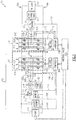
- FIG. 1 schematically illustrates an example electrical power system 10 for a vehicle, such as an electric or hybrid military ground or underwater vehicle, that includes a power generating section 12 and a plurality of DC loads 14.
- the power generating section 12 powers the plurality of DC loads 14 over a DC bus that includes a positive rail 16A and a negative rail 16B, collectively referred to herein as DC bus 16.
- the DC loads 14 include at least one base load and at least one pulse (dynamic) load.
- the at least one base load tends to have a more constant power usage, and may include items such as an export inverter (e.g., for plugging in an alternating current (AC) appliance in a vehicle), or a vehicle HVAC system, for example.
- the at least one pulse load has a more variable power usage (peak power), and may include items such as one or more traction drive motors of an electric vehicle, a radar, or a laser or microwave-based weapon (e.g., a directed-energy weapon or "DEW").
- a traction drive motor for example, may perform rapid acceleration during which additional voltage is needed on the DC bus 16, and may perform rapid deceleration, potentially in connection with regenerative braking, where excess voltage may be provided on the DC bus 16.
- the electrical power system 10 also includes a motor drive circuit 18 that operates as a pulse width modulated inverter to cause a multiphase AC machine 20 to operate as a motor and drive a rotor 22 that drives one or more motor-driven loads 24 (e.g., an oil pump, an air compressor, an actuator, a cooling fan, an HVAC component, and/or a traction drive motor).
- the motor drive circuit 18 includes a plurality of switching legs 26A-C that are operated as a multiphase pulse width modulated inverter to convert DC power from the DC bus 16 to variable voltage variable frequency power supplied to a plurality of stator windings A2, B2, C2 of the multiphase AC motor 20.
- the power generating section 12 also includes a battery 30 that is a lithium-ion battery in some non-limiting examples, and includes a battery charger 32 that is operable to charge the battery 30 from the DC bus 16 when connected to the battery 30.
- the power generating section 12 also includes a multiphase AC machine 34 that includes a plurality of windings A1, B1, C1 and is separate from the multiphase AC machine 20.
- the AC machine 20 and/or the AC machine 34 are brushless machines, such as a permanent magnet synchronous machines (PMSMs), and the plurality of windings A1, B1, C1 and/or A2, B2, C2 are arranged in a wye formation.
- PMSM permanent magnet synchronous machines
- a PMSM uses rotating permanent magnets to provide an electrical field that induces a current in a plurality of stator windings.
- AC machines could be used, such as ones that can operate as an axial flux machine, a wound field synchronous machine, or an induction machine, and other winding formations could be used as well.
- the power generating section 12 includes a multifunctional converter circuit 40 that utilizes stator windings A1, B1, C1 of the multiphase AC machine 34 to act as a DC-DC boost converter or an active rectifier in different operating modes.
- the multifunctional converter 40 may also operate as an inverter to provide electric engine start.
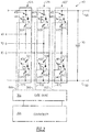
- the multifunctional converter circuit 40 has a plurality of switching legs 42A-C, which are illustrated in more detail in Figure 2 .
- the multifunctional converter circuit 40 described below is a 2-level power converter that is well-known for use as an inverter. However, other topologies, such as multilevel power converter can also be utilized in this invention.
- each switching leg 42 includes a pair of power switches 44 and 46, and controls connection of a respective one of the windings A1, B1, C1 of the AC machine 34 to the DC bus 16.
- the first power switch 44 has a first node 48 connected to the positive rail 16A of the DC bus 16 and also has a second node 50.
- the second power switch 46 has a first node 52 connected to the second node 50 of the first power switch 44, and also has a second node 54 connected to the negative rail 16B of the DC bus 16.
- each winding A1, B1, C1 is connected to the nodes 50, 52 of its respective switching leg 42.
- Each power switch 44 is connected in parallel to an associated freewheeling diode 60
- each power switch 46 is also connected in parallel to an associated freewheeling diode 62.
- the freewheeling diodes 60, 62 form a current path when their respective power switches 44, 46 are turned off.
- a controller 36A operates its associated gate drive 38A to control the power switches 44, 46 over control lines 66A-C and 67A-C.
- the power switches 44, 46 are shown as being metal-oxide semiconductor field-effect transistors (MOSFETs) in Figure 2 , it is understood that other types of power switches could be used, such as insulated-gate bipolar transistors (IGBTs).
- MOSFETs metal-oxide semiconductor field-effect transistors
- IGBTs insulated-gate bipolar transistors
- each switching leg 26A-C of the motor drive circuit 18 are arranged the same as the switching legs 42A-C of converter circuit 40 except that the switching legs 26A-C are connected to windings A2, B2, C2 instead of windings A1, B1, C1.
- each switching leg 26A-C includes a pair of power switches, and controls connection of a respective one of the windings A2, B2, C2 of the AC machine 20 to the DC bus 16.
- Each power switch of the switching legs 26A-C is also connected in parallel to a respective freewheeling diode.
- MOSFETs metal-oxide semiconductor field-effect transistors
- IGBTs insulated-gate bipolar transistors
- the battery 30 is connectable to three different circuit paths 72, 74, 76 for different operating modes of the power generating section 12.
- a first "active rectification” mode which uses circuit path 72
- the multifunctional converter circuit 40 utilizes the plurality of windings A1, B1, C1 and functions as an active rectifier to supply DC power to the DC loads and to charge the battery 30 through the battery charger 32.
- a second "boost converter” mode which uses circuit path 76, the multifunctional converter circuit 40 utilizes the plurality of windings A1, B1, C1 and functions as a boost converter to supply DC power to the DC loads via DC bus 16 by converting a variable voltage of the battery 30 to a constant voltage on the DC bus 16.
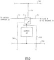
- FIG 3 is an enlarged view of a battery switching circuit S1 of the electrical power system 10 that controls which one of the circuit paths 72, 74, 76 is connected to a node 70 of the battery 30.
- the switching circuit S1 includes a three position switch in some examples. Referring now to Figure 3 , in the first "active rectification" mode, the switching circuit S1 connects node 70 of the battery 30 to circuit path 72, which connects to battery charger 32 for charging the battery 30.
- the circuit path 72 excludes the plurality of windings A1, B1, C1.
- the prime mover engine 80 is running, and rotates rotor 82 which drives operation of the multiphase AC machine 34 to induce an electrical current in the plurality of windings A1, B1, and C1 and operate the multiphase AC machine 34 as a generator.
- the prime mover engine 80 is an internal combustion engine (e.g., diesel or gasoline) or a gas turbine engine in some examples.
- the prime mover engine 80 is a gas turbine engine, such as in a tank.
- the prime mover engine 80 uses fuel from a fuel source (not shown).
- the controller 36A operates the plurality of switching legs 42A-C as a pulse width modulated active rectifier to rectify AC from the plurality of windings A1, B1, C1 to DC for the DC bus 16.
- the battery charger 32 uses the DC on the DC bus to charge the battery 30.
- the controller 36A utilizes a field oriented control using a known sensorless technique, optionally using a position sensor (not shown) for rotor 82.
- the power generating section 12 can enter the first mode when the prime mover engine 80 is started and has reached a threshold speed.
- the controller 36A performs pulse width modulation on the switching legs 42A-C to operate the multifunctional converter circuit 40 as a pulse width modulated active rectifier.
- the active rectification mode can extend the range of an electric or hybrid vehicle using the battery 30, by charging the battery 30 when its charge is depleted.
- the plurality of windings A1, B1, C1 are operated as boost inductors during active rectifier operation in the first mode.
- the switching circuit S1 connects the output node 70 of the battery 30 to a neutral N of the AC machine 34 through circuit path 76.
- the controller 36A operates the multifunctional converter circuit 40 to utilize the plurality of windings A1, B1, C1 and function as a boost converter that converts an output voltage of the battery 30 to a controlled DC bus voltage on DC bus 16 at a specified voltage level during "silent" operation when the battery 30 voltage gradually reduces.
- the prime mover engine 80 is not operating during the second mode, which in hybrid vehicles is known as a "silent mode" due to the quiet way in which traction motors run on battery power alone.
- the controller 36A uses an interleaved technique by parallel connection of three channels of boost converters, with each "channel" corresponding to a current phase on a respective one of the windings A1, B1, C1.
- the controller 36A performs phase shifting of the pulse width modulation frequencies for each phase by 120° between channels.
- the interleaved technique reduces the total input and output current of the plurality of windings A1, B1, C1, and also significantly reduces input and output current ripple on the DC bus 16 and battery 30.
- the battery 30 is connected to the DC bus 16 through current path 74.
- the controller 36A operates the plurality of switching legs 42A-C of the multifunctional converter circuit 40 as a motor drive pulse-width modulated inverter that converts DC power from the battery 30, as received over the DC bus, to a variable voltage variable frequency power to the plurality of windings A1, B1, C1 (stator windings of AC machine 34). This operates the AC machine 34 in a motoring mode, to rotate rotor 82 and provide electric start of the prime mover engine 80.
- the controller 36A uses a field oriented motor control using a known sensorless technique.
- the controller 36A may optionally use a motor rotor position sensor (not shown) which is operable to detect a position of the rotor 82 of the prime mover engine 80 to perform the engine start in the third mode.
- the battery 30 may be re-connected from the charger 32 to the DC bus 16 during active rectification mode if the battery is fully (or near fully) charged.
- the power generating section 12 enters the third mode when a charge of battery 30 is depleted beneath a charge level threshold, and the controller 36A needs to start the prime mover engine 80 from the battery 30 (e.g., as part of a range extender).
- the multifunctional converter circuit 40 also includes a DC link capacitor 90 that is connected across the DC bus 16 in parallel to the various switching legs 42, 26.
- the DC link capacitor 90 reduces DC bus voltage ripple and helps to stabilize the power generating system in presence of constant power (negative impedance) loads.
- the switching legs 26A-C of motor drive circuit 18 are operated in a similar fashion to how the switching legs 42A-C of converter circuit 40 are operated during the third mode.
- the plurality of switching legs 26A-C of motor drive circuit 18 are operated as a pulse width modulated inverter to provide AC to the plurality of windings A2, B2, C2 to drive rotor 22.
- the controller 36B operates its associated gate drive 38B to control the switching legs 26A-C in this fashion.
- the electrical power system 10 includes a plurality of lines 100-116 used by the controllers 36A and/or 36B for controlling and/or sensing in the electrical power system 10.
- Lines 100, 108 are used to detect and/or measure a voltage on the DC bus 16.
- Control line 102 is used for controlling an operational state of switching circuit S1.
- Lines 104, 108 are used to measure a voltage of the battery 30.
- Sensing line 106 is used to detect and/or measure electrical current of the windings A1, B1, C1 from current sensors 107A, 107B, 107C. Although a single current sensing line 106 is schematically shown, it is understood that each winding A1, B1, C1 may have its own current sensing line 106. Lines 110, 112 are used to detect and/or measure voltage of the DC bus 16 (redundant sensing of DC bus 16). Sensing line 114 is used to detect and/or measure an electrical current of the windings A2, B2, C2 from current sensors 115A, 115B, 115C.
- each winding A2, B2, C2 may have its own current sensing line 115.
- Control line 116 is used to detect a temperature of the AC machine 20 and/or its rotor 22. Additional sensing lines (not shown) may be included to detect the rotational positions of rotors 22, 82.
- the controllers 36A-B are powered by an interface circuit 120 that may also communicate with other vehicle controls (not shown).
- the interface circuit 120 obtains its power from power circuit 122.
- the power circuit 122 provides 28 volt DC power to the interface circuit 120.
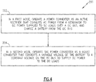
- Figure 4 illustrates an example method 200 of operating the electrical power system 10.
- a power converter e.g., that includes multifunctional converter circuit 40 and controller 36A
- a generator e.g., AC machine 34 operating as a generator
- circuit path 72 is used in the first mode.
- the power converter is operated as a boost converter that converts a variable output voltage of the battery 30 to a specified constant voltage on the DC bus 16 to supply DC power to the DC loads 14 (block 204).
- the power converter utilizes the plurality of windings A1, B1, C1 of multiphase AC machine 34 when operated as the active rectifier and boost converter.
- circuit path 76 is used in the second mode.
- circuit path 74 is used during the third mode, in which battery 30 powers the multifunctional converter circuit 40 via DC bus to supply variable voltage variable frequency power to the stator windings A1, B1, C1 of the AC machine to start the prime mover engine 80.
- the electrical power system 10 provides an improved and simplified architecture that eliminates the additional DC-DC boost converter typically present in prior art systems. This provides a weight, volume, and cost reduction, and can also reduce electromagnetic interference (EMI).
- the improved architecture can also simplify thermal management and provide increased reliability through elimination of the additional DC-DC boost converter, because eliminating the additional DC-DC boost converter can also facilitate elimination of a dedicated thermal management system of the eliminated boost converter.
- AC machine 20 for driving the one or more motor-driven loads 24, it is understood that the outputs of motor drive circuit 18 could be used to drive a plurality of AC machines 20 for a plurality of motor-driven loads 24.
Landscapes
- Engineering & Computer Science (AREA)
- Power Engineering (AREA)
- Transportation (AREA)
- Mechanical Engineering (AREA)
- Life Sciences & Earth Sciences (AREA)
- Sustainable Development (AREA)
- Sustainable Energy (AREA)
- Electric Propulsion And Braking For Vehicles (AREA)
Applications Claiming Priority (1)
| Application Number | Priority Date | Filing Date | Title |
|---|---|---|---|
| US15/658,845 US10661677B2 (en) | 2017-07-25 | 2017-07-25 | Electrical power system for hybrid or electric vehicle |
Publications (2)
| Publication Number | Publication Date |
|---|---|
| EP3441255A1 true EP3441255A1 (de) | 2019-02-13 |
| EP3441255B1 EP3441255B1 (de) | 2021-02-24 |
Family
ID=63047264
Family Applications (1)
| Application Number | Title | Priority Date | Filing Date |
|---|---|---|---|
| EP18185588.3A Active EP3441255B1 (de) | 2017-07-25 | 2018-07-25 | Stromsystem für hybrid- oder elektrofahrzeug |
Country Status (2)
| Country | Link |
|---|---|
| US (1) | US10661677B2 (de) |
| EP (1) | EP3441255B1 (de) |
Families Citing this family (5)
| Publication number | Priority date | Publication date | Assignee | Title |
|---|---|---|---|---|
| KR102797069B1 (ko) * | 2020-06-05 | 2025-04-18 | 현대자동차주식회사 | 차량 및 차량의 제어방법 |
| CN112224039B (zh) * | 2020-09-18 | 2024-06-25 | 盐城工学院 | 一种电动汽车增程器及控制方法 |
| US11569753B1 (en) * | 2021-10-20 | 2023-01-31 | Honeywell Limited | Apparatuses and methods for an alternating current to direct current converter |
| CN114228754A (zh) * | 2021-12-18 | 2022-03-25 | 中车永济电机有限公司 | 一种混合动力调车机车电传动系统 |
| US12233716B2 (en) * | 2022-09-23 | 2025-02-25 | Ford Global Technologies, Llc | Automotive electric drive with three phase coupled inverter |
Citations (2)
| Publication number | Priority date | Publication date | Assignee | Title |
|---|---|---|---|---|
| US20120007428A1 (en) * | 2010-07-12 | 2012-01-12 | Hamilton Sundstrand Corporation | Electric Power Generating System with Boost Converter/Synchronous Active Filter |
| US20170149368A1 (en) * | 2014-09-17 | 2017-05-25 | Arm Limited | Motor driver and a method of operating thereof |
Family Cites Families (17)
| Publication number | Priority date | Publication date | Assignee | Title |
|---|---|---|---|---|
| DE4011291A1 (de) | 1990-04-06 | 1991-10-17 | Magnet Motor Gmbh | Elektrofahrzeug mit einzeln gesteuerten antriebs-elektromotoren |
| US7439634B2 (en) | 2004-08-24 | 2008-10-21 | Honeywell International Inc. | Electrical starting, generation, conversion and distribution system architecture for a more electric vehicle |
| US7406370B2 (en) | 2004-08-24 | 2008-07-29 | Honeywell International Inc. | Electrical energy management system on a more electric vehicle |
| US8238130B2 (en) * | 2008-09-30 | 2012-08-07 | General Electric Company | Low-mass, bi-directional DC-AC interface unit |
| US8299762B2 (en) | 2009-06-05 | 2012-10-30 | Hamilton Sundstrand Corporation | Starting/generating system with multi-functional circuit breaker |
| JP5359637B2 (ja) * | 2009-07-17 | 2013-12-04 | 富士電機株式会社 | 電力変換装置 |
| JP5686131B2 (ja) * | 2010-02-17 | 2015-03-18 | 富士電機株式会社 | 電力変換装置 |
| US9266441B2 (en) * | 2011-01-19 | 2016-02-23 | Technova Inc. | Contactless power transfer system |
| KR101631085B1 (ko) | 2011-05-04 | 2016-06-16 | 엘지전자 주식회사 | 전기 자동차 및 이의 구동 방법 |
| WO2013097824A1 (zh) * | 2011-12-31 | 2013-07-04 | 深圳市比亚迪汽车研发有限公司 | 电动汽车及用于电动汽车的动力系统和电机控制器 |
| JP2013183497A (ja) * | 2012-02-29 | 2013-09-12 | Equos Research Co Ltd | 電力伝送システム |
| US9077237B2 (en) | 2012-10-31 | 2015-07-07 | Honeywell International Inc. | Composite AC-to-DC power converter with boosting capabilities |
| JP2014143185A (ja) * | 2012-12-28 | 2014-08-07 | Semiconductor Energy Lab Co Ltd | 蓄電装置及びその充電方法 |
| JP5920329B2 (ja) * | 2013-12-24 | 2016-05-18 | トヨタ自動車株式会社 | 車両 |
| US9783070B2 (en) | 2014-02-14 | 2017-10-10 | Jabil Circuit, Inc. | Charge transfer system |
| EP3151361B1 (de) * | 2014-05-30 | 2020-09-23 | Fuji Electric Co., Ltd. | Ladegerät |
| EP2966749A3 (de) * | 2014-06-20 | 2016-04-06 | Funai Electric Co., Ltd. | Drahtloses stromversorgungssystem |
-
2017
- 2017-07-25 US US15/658,845 patent/US10661677B2/en active Active
-
2018
- 2018-07-25 EP EP18185588.3A patent/EP3441255B1/de active Active
Patent Citations (2)
| Publication number | Priority date | Publication date | Assignee | Title |
|---|---|---|---|---|
| US20120007428A1 (en) * | 2010-07-12 | 2012-01-12 | Hamilton Sundstrand Corporation | Electric Power Generating System with Boost Converter/Synchronous Active Filter |
| US20170149368A1 (en) * | 2014-09-17 | 2017-05-25 | Arm Limited | Motor driver and a method of operating thereof |
Also Published As
| Publication number | Publication date |
|---|---|
| US20190031041A1 (en) | 2019-01-31 |
| US10661677B2 (en) | 2020-05-26 |
| EP3441255B1 (de) | 2021-02-24 |
Similar Documents
| Publication | Publication Date | Title |
|---|---|---|
| US10525833B2 (en) | Tactical vehicle to grid electric power architecture | |
| EP3434508A1 (de) | Elektrische systemarchitektur für bereichserweiterte elektrische fahrzeuge | |
| EP3441255B1 (de) | Stromsystem für hybrid- oder elektrofahrzeug | |
| US9099882B2 (en) | Turbine engine hybrid power supply | |
| US7822535B2 (en) | Internal combustion engine stop controller and stop control method | |
| CN104024029B (zh) | 电动车控制装置以及电动车 | |
| US10236803B2 (en) | Hybrid-vehicle variable-voltage traction motor drive | |
| KR101766094B1 (ko) | 하이브리드 차량의 출력 제어 시스템 | |
| US8497591B2 (en) | System and method for off-highway vehicle engine cranking | |
| CN102195411B (zh) | 具有集成电力和控制且包括电流源逆变器的电机 | |
| CN101636901A (zh) | 具有多个发电机和/或逆变器的发电系统 | |
| US10063097B2 (en) | Segmented waveform converter on controlled field variable speed generator | |
| CN106941333A (zh) | 具有分段波形转换器的混合型装置 | |
| CN104993580B (zh) | 油电混合直流供电装置 | |
| JP2011162178A (ja) | 車両搭載用発電装置 | |
| CN101926087B (zh) | 旋转电机控制系统以及车辆驱动系统 | |
| EP3689657B1 (de) | Hybridfahrzeug und stromversorgungssystem dafür | |
| EP2719888A1 (de) | Startergenerator für einen Dualer-Gleichstrom-Bus | |
| JP2025008106A (ja) | 車載充電装置 | |
| JP5822697B2 (ja) | 発電システム及びその運転制御方法 | |
| JP5755583B2 (ja) | 電力制御システム | |
| RU2556236C1 (ru) | Преобразовательный комплекс электроснабжения собственных нужд тепловоза | |
| Grzesiak et al. | „Power mangament in series hybrid drive” | |
| Huang et al. | Efficient energy management for electrical scooters | |
| JP2025032629A (ja) | 車載充電装置 |
Legal Events
| Date | Code | Title | Description |
|---|---|---|---|
| PUAI | Public reference made under article 153(3) epc to a published international application that has entered the european phase |
Free format text: ORIGINAL CODE: 0009012 |
|
| STAA | Information on the status of an ep patent application or granted ep patent |
Free format text: STATUS: THE APPLICATION HAS BEEN PUBLISHED |
|
| AK | Designated contracting states |
Kind code of ref document: A1 Designated state(s): AL AT BE BG CH CY CZ DE DK EE ES FI FR GB GR HR HU IE IS IT LI LT LU LV MC MK MT NL NO PL PT RO RS SE SI SK SM TR |
|
| AX | Request for extension of the european patent |
Extension state: BA ME |
|
| STAA | Information on the status of an ep patent application or granted ep patent |
Free format text: STATUS: REQUEST FOR EXAMINATION WAS MADE |
|
| 17P | Request for examination filed |
Effective date: 20190809 |
|
| RBV | Designated contracting states (corrected) |
Designated state(s): AL AT BE BG CH CY CZ DE DK EE ES FI FR GB GR HR HU IE IS IT LI LT LU LV MC MK MT NL NO PL PT RO RS SE SI SK SM TR |
|
| REG | Reference to a national code |
Ref country code: DE Ref legal event code: R079 Ref document number: 602018012931 Country of ref document: DE Free format text: PREVIOUS MAIN CLASS: B60L0050150000 Ipc: B60L0053240000 |
|
| RIC1 | Information provided on ipc code assigned before grant |
Ipc: B60L 50/15 20190101ALI20200707BHEP Ipc: B60L 53/24 20190101AFI20200707BHEP |
|
| GRAP | Despatch of communication of intention to grant a patent |
Free format text: ORIGINAL CODE: EPIDOSNIGR1 |
|
| STAA | Information on the status of an ep patent application or granted ep patent |
Free format text: STATUS: GRANT OF PATENT IS INTENDED |
|
| INTG | Intention to grant announced |
Effective date: 20200901 |
|
| GRAS | Grant fee paid |
Free format text: ORIGINAL CODE: EPIDOSNIGR3 |
|
| GRAA | (expected) grant |
Free format text: ORIGINAL CODE: 0009210 |
|
| STAA | Information on the status of an ep patent application or granted ep patent |
Free format text: STATUS: THE PATENT HAS BEEN GRANTED |
|
| AK | Designated contracting states |
Kind code of ref document: B1 Designated state(s): AL AT BE BG CH CY CZ DE DK EE ES FI FR GB GR HR HU IE IS IT LI LT LU LV MC MK MT NL NO PL PT RO RS SE SI SK SM TR |
|
| REG | Reference to a national code |
Ref country code: CH Ref legal event code: EP |
|
| REG | Reference to a national code |
Ref country code: AT Ref legal event code: REF Ref document number: 1364022 Country of ref document: AT Kind code of ref document: T Effective date: 20210315 |
|
| REG | Reference to a national code |
Ref country code: IE Ref legal event code: FG4D |
|
| REG | Reference to a national code |
Ref country code: DE Ref legal event code: R096 Ref document number: 602018012931 Country of ref document: DE |
|
| REG | Reference to a national code |
Ref country code: LT Ref legal event code: MG9D |
|
| REG | Reference to a national code |
Ref country code: NL Ref legal event code: MP Effective date: 20210224 |
|
| PG25 | Lapsed in a contracting state [announced via postgrant information from national office to epo] |
Ref country code: GR Free format text: LAPSE BECAUSE OF FAILURE TO SUBMIT A TRANSLATION OF THE DESCRIPTION OR TO PAY THE FEE WITHIN THE PRESCRIBED TIME-LIMIT Effective date: 20210525 Ref country code: HR Free format text: LAPSE BECAUSE OF FAILURE TO SUBMIT A TRANSLATION OF THE DESCRIPTION OR TO PAY THE FEE WITHIN THE PRESCRIBED TIME-LIMIT Effective date: 20210224 Ref country code: FI Free format text: LAPSE BECAUSE OF FAILURE TO SUBMIT A TRANSLATION OF THE DESCRIPTION OR TO PAY THE FEE WITHIN THE PRESCRIBED TIME-LIMIT Effective date: 20210224 Ref country code: BG Free format text: LAPSE BECAUSE OF FAILURE TO SUBMIT A TRANSLATION OF THE DESCRIPTION OR TO PAY THE FEE WITHIN THE PRESCRIBED TIME-LIMIT Effective date: 20210524 Ref country code: LT Free format text: LAPSE BECAUSE OF FAILURE TO SUBMIT A TRANSLATION OF THE DESCRIPTION OR TO PAY THE FEE WITHIN THE PRESCRIBED TIME-LIMIT Effective date: 20210224 Ref country code: PT Free format text: LAPSE BECAUSE OF FAILURE TO SUBMIT A TRANSLATION OF THE DESCRIPTION OR TO PAY THE FEE WITHIN THE PRESCRIBED TIME-LIMIT Effective date: 20210624 Ref country code: NO Free format text: LAPSE BECAUSE OF FAILURE TO SUBMIT A TRANSLATION OF THE DESCRIPTION OR TO PAY THE FEE WITHIN THE PRESCRIBED TIME-LIMIT Effective date: 20210524 |
|
| REG | Reference to a national code |
Ref country code: AT Ref legal event code: MK05 Ref document number: 1364022 Country of ref document: AT Kind code of ref document: T Effective date: 20210224 |
|
| PG25 | Lapsed in a contracting state [announced via postgrant information from national office to epo] |
Ref country code: LV Free format text: LAPSE BECAUSE OF FAILURE TO SUBMIT A TRANSLATION OF THE DESCRIPTION OR TO PAY THE FEE WITHIN THE PRESCRIBED TIME-LIMIT Effective date: 20210224 Ref country code: RS Free format text: LAPSE BECAUSE OF FAILURE TO SUBMIT A TRANSLATION OF THE DESCRIPTION OR TO PAY THE FEE WITHIN THE PRESCRIBED TIME-LIMIT Effective date: 20210224 Ref country code: PL Free format text: LAPSE BECAUSE OF FAILURE TO SUBMIT A TRANSLATION OF THE DESCRIPTION OR TO PAY THE FEE WITHIN THE PRESCRIBED TIME-LIMIT Effective date: 20210224 Ref country code: NL Free format text: LAPSE BECAUSE OF FAILURE TO SUBMIT A TRANSLATION OF THE DESCRIPTION OR TO PAY THE FEE WITHIN THE PRESCRIBED TIME-LIMIT Effective date: 20210224 Ref country code: SE Free format text: LAPSE BECAUSE OF FAILURE TO SUBMIT A TRANSLATION OF THE DESCRIPTION OR TO PAY THE FEE WITHIN THE PRESCRIBED TIME-LIMIT Effective date: 20210224 |
|
| PG25 | Lapsed in a contracting state [announced via postgrant information from national office to epo] |
Ref country code: IS Free format text: LAPSE BECAUSE OF FAILURE TO SUBMIT A TRANSLATION OF THE DESCRIPTION OR TO PAY THE FEE WITHIN THE PRESCRIBED TIME-LIMIT Effective date: 20210624 |
|
| PG25 | Lapsed in a contracting state [announced via postgrant information from national office to epo] |
Ref country code: CZ Free format text: LAPSE BECAUSE OF FAILURE TO SUBMIT A TRANSLATION OF THE DESCRIPTION OR TO PAY THE FEE WITHIN THE PRESCRIBED TIME-LIMIT Effective date: 20210224 Ref country code: EE Free format text: LAPSE BECAUSE OF FAILURE TO SUBMIT A TRANSLATION OF THE DESCRIPTION OR TO PAY THE FEE WITHIN THE PRESCRIBED TIME-LIMIT Effective date: 20210224 Ref country code: AT Free format text: LAPSE BECAUSE OF FAILURE TO SUBMIT A TRANSLATION OF THE DESCRIPTION OR TO PAY THE FEE WITHIN THE PRESCRIBED TIME-LIMIT Effective date: 20210224 Ref country code: SM Free format text: LAPSE BECAUSE OF FAILURE TO SUBMIT A TRANSLATION OF THE DESCRIPTION OR TO PAY THE FEE WITHIN THE PRESCRIBED TIME-LIMIT Effective date: 20210224 |
|
| REG | Reference to a national code |
Ref country code: DE Ref legal event code: R097 Ref document number: 602018012931 Country of ref document: DE |
|
| PG25 | Lapsed in a contracting state [announced via postgrant information from national office to epo] |
Ref country code: RO Free format text: LAPSE BECAUSE OF FAILURE TO SUBMIT A TRANSLATION OF THE DESCRIPTION OR TO PAY THE FEE WITHIN THE PRESCRIBED TIME-LIMIT Effective date: 20210224 Ref country code: DK Free format text: LAPSE BECAUSE OF FAILURE TO SUBMIT A TRANSLATION OF THE DESCRIPTION OR TO PAY THE FEE WITHIN THE PRESCRIBED TIME-LIMIT Effective date: 20210224 Ref country code: SK Free format text: LAPSE BECAUSE OF FAILURE TO SUBMIT A TRANSLATION OF THE DESCRIPTION OR TO PAY THE FEE WITHIN THE PRESCRIBED TIME-LIMIT Effective date: 20210224 |
|
| PLBE | No opposition filed within time limit |
Free format text: ORIGINAL CODE: 0009261 |
|
| STAA | Information on the status of an ep patent application or granted ep patent |
Free format text: STATUS: NO OPPOSITION FILED WITHIN TIME LIMIT |
|
| PG25 | Lapsed in a contracting state [announced via postgrant information from national office to epo] |
Ref country code: AL Free format text: LAPSE BECAUSE OF FAILURE TO SUBMIT A TRANSLATION OF THE DESCRIPTION OR TO PAY THE FEE WITHIN THE PRESCRIBED TIME-LIMIT Effective date: 20210224 Ref country code: ES Free format text: LAPSE BECAUSE OF FAILURE TO SUBMIT A TRANSLATION OF THE DESCRIPTION OR TO PAY THE FEE WITHIN THE PRESCRIBED TIME-LIMIT Effective date: 20210224 |
|
| 26N | No opposition filed |
Effective date: 20211125 |
|
| PG25 | Lapsed in a contracting state [announced via postgrant information from national office to epo] |
Ref country code: SI Free format text: LAPSE BECAUSE OF FAILURE TO SUBMIT A TRANSLATION OF THE DESCRIPTION OR TO PAY THE FEE WITHIN THE PRESCRIBED TIME-LIMIT Effective date: 20210224 |
|
| REG | Reference to a national code |
Ref country code: CH Ref legal event code: PL |
|
| PG25 | Lapsed in a contracting state [announced via postgrant information from national office to epo] |
Ref country code: MC Free format text: LAPSE BECAUSE OF FAILURE TO SUBMIT A TRANSLATION OF THE DESCRIPTION OR TO PAY THE FEE WITHIN THE PRESCRIBED TIME-LIMIT Effective date: 20210224 |
|
| REG | Reference to a national code |
Ref country code: BE Ref legal event code: MM Effective date: 20210731 |
|
| PG25 | Lapsed in a contracting state [announced via postgrant information from national office to epo] |
Ref country code: LI Free format text: LAPSE BECAUSE OF NON-PAYMENT OF DUE FEES Effective date: 20210731 Ref country code: IT Free format text: LAPSE BECAUSE OF FAILURE TO SUBMIT A TRANSLATION OF THE DESCRIPTION OR TO PAY THE FEE WITHIN THE PRESCRIBED TIME-LIMIT Effective date: 20210224 Ref country code: CH Free format text: LAPSE BECAUSE OF NON-PAYMENT OF DUE FEES Effective date: 20210731 |
|
| PG25 | Lapsed in a contracting state [announced via postgrant information from national office to epo] |
Ref country code: IS Free format text: LAPSE BECAUSE OF FAILURE TO SUBMIT A TRANSLATION OF THE DESCRIPTION OR TO PAY THE FEE WITHIN THE PRESCRIBED TIME-LIMIT Effective date: 20210624 Ref country code: LU Free format text: LAPSE BECAUSE OF NON-PAYMENT OF DUE FEES Effective date: 20210725 |
|
| PG25 | Lapsed in a contracting state [announced via postgrant information from national office to epo] |
Ref country code: IE Free format text: LAPSE BECAUSE OF NON-PAYMENT OF DUE FEES Effective date: 20210725 Ref country code: BE Free format text: LAPSE BECAUSE OF NON-PAYMENT OF DUE FEES Effective date: 20210731 |
|
| P01 | Opt-out of the competence of the unified patent court (upc) registered |
Effective date: 20230522 |
|
| PG25 | Lapsed in a contracting state [announced via postgrant information from national office to epo] |
Ref country code: CY Free format text: LAPSE BECAUSE OF FAILURE TO SUBMIT A TRANSLATION OF THE DESCRIPTION OR TO PAY THE FEE WITHIN THE PRESCRIBED TIME-LIMIT Effective date: 20210224 |
|
| PG25 | Lapsed in a contracting state [announced via postgrant information from national office to epo] |
Ref country code: HU Free format text: LAPSE BECAUSE OF FAILURE TO SUBMIT A TRANSLATION OF THE DESCRIPTION OR TO PAY THE FEE WITHIN THE PRESCRIBED TIME-LIMIT; INVALID AB INITIO Effective date: 20180725 |
|
| PG25 | Lapsed in a contracting state [announced via postgrant information from national office to epo] |
Ref country code: MK Free format text: LAPSE BECAUSE OF FAILURE TO SUBMIT A TRANSLATION OF THE DESCRIPTION OR TO PAY THE FEE WITHIN THE PRESCRIBED TIME-LIMIT Effective date: 20210224 |
|
| PG25 | Lapsed in a contracting state [announced via postgrant information from national office to epo] |
Ref country code: MT Free format text: LAPSE BECAUSE OF FAILURE TO SUBMIT A TRANSLATION OF THE DESCRIPTION OR TO PAY THE FEE WITHIN THE PRESCRIBED TIME-LIMIT Effective date: 20210224 |
|
| PGFP | Annual fee paid to national office [announced via postgrant information from national office to epo] |
Ref country code: GB Payment date: 20250619 Year of fee payment: 8 |
|
| PGFP | Annual fee paid to national office [announced via postgrant information from national office to epo] |
Ref country code: FR Payment date: 20250620 Year of fee payment: 8 |
|
| PGFP | Annual fee paid to national office [announced via postgrant information from national office to epo] |
Ref country code: DE Payment date: 20250620 Year of fee payment: 8 |
|
| PG25 | Lapsed in a contracting state [announced via postgrant information from national office to epo] |
Ref country code: TR Free format text: LAPSE BECAUSE OF FAILURE TO SUBMIT A TRANSLATION OF THE DESCRIPTION OR TO PAY THE FEE WITHIN THE PRESCRIBED TIME-LIMIT Effective date: 20210224 |