EP3441245B1 - Dispositif d'aération - Google Patents
Dispositif d'aération Download PDFInfo
- Publication number
- EP3441245B1 EP3441245B1 EP18187260.7A EP18187260A EP3441245B1 EP 3441245 B1 EP3441245 B1 EP 3441245B1 EP 18187260 A EP18187260 A EP 18187260A EP 3441245 B1 EP3441245 B1 EP 3441245B1
- Authority
- EP
- European Patent Office
- Prior art keywords
- elements
- surface elements
- ventilating device
- flexible
- ventilation device
- Prior art date
- Legal status (The legal status is an assumption and is not a legal conclusion. Google has not performed a legal analysis and makes no representation as to the accuracy of the status listed.)
- Active
Links
Images


Classifications
-
- F—MECHANICAL ENGINEERING; LIGHTING; HEATING; WEAPONS; BLASTING
- F24—HEATING; RANGES; VENTILATING
- F24F—AIR-CONDITIONING; AIR-HUMIDIFICATION; VENTILATION; USE OF AIR CURRENTS FOR SCREENING
- F24F13/00—Details common to, or for air-conditioning, air-humidification, ventilation or use of air currents for screening
- F24F13/02—Ducting arrangements
- F24F13/06—Outlets for directing or distributing air into rooms or spaces, e.g. ceiling air diffuser
- F24F13/078—Outlets for directing or distributing air into rooms or spaces, e.g. ceiling air diffuser combined with lighting fixtures
-
- B—PERFORMING OPERATIONS; TRANSPORTING
- B60—VEHICLES IN GENERAL
- B60H—ARRANGEMENTS OF HEATING, COOLING, VENTILATING OR OTHER AIR-TREATING DEVICES SPECIALLY ADAPTED FOR PASSENGER OR GOODS SPACES OF VEHICLES
- B60H1/00—Heating, cooling or ventilating devices
- B60H1/34—Nozzles; Air-diffusers
- B60H1/3407—Nozzles; Air-diffusers providing an air stream in a fixed direction, e.g. using a grid or porous panel
-
- F—MECHANICAL ENGINEERING; LIGHTING; HEATING; WEAPONS; BLASTING
- F24—HEATING; RANGES; VENTILATING
- F24F—AIR-CONDITIONING; AIR-HUMIDIFICATION; VENTILATION; USE OF AIR CURRENTS FOR SCREENING
- F24F13/00—Details common to, or for air-conditioning, air-humidification, ventilation or use of air currents for screening
- F24F13/02—Ducting arrangements
- F24F13/06—Outlets for directing or distributing air into rooms or spaces, e.g. ceiling air diffuser
-
- B—PERFORMING OPERATIONS; TRANSPORTING
- B60—VEHICLES IN GENERAL
- B60H—ARRANGEMENTS OF HEATING, COOLING, VENTILATING OR OTHER AIR-TREATING DEVICES SPECIALLY ADAPTED FOR PASSENGER OR GOODS SPACES OF VEHICLES
- B60H1/00—Heating, cooling or ventilating devices
- B60H1/34—Nozzles; Air-diffusers
- B60H2001/3471—Details of actuators
-
- B—PERFORMING OPERATIONS; TRANSPORTING
- B60—VEHICLES IN GENERAL
- B60H—ARRANGEMENTS OF HEATING, COOLING, VENTILATING OR OTHER AIR-TREATING DEVICES SPECIALLY ADAPTED FOR PASSENGER OR GOODS SPACES OF VEHICLES
- B60H1/00—Heating, cooling or ventilating devices
- B60H1/34—Nozzles; Air-diffusers
- B60H2001/3492—Manufacturing; Assembling
Definitions
- a ventilation device which has surface elements which abut one another in a first position in order to provide a closed surface and are arranged at a distance from one another in a second position in order to form air outlet openings.
- Generic ventilation devices are generally provided to provide diffuse ventilation. In the case of diffuse ventilation, an air stream is output without a directed air deflection, as is possible, for example, via controllable air vents.
- Such ventilation devices should generally only provide an air supply.
- Ventilation devices are used, for example, in vehicles to bring fresh air, tempered air and / or conditioned air into the passenger compartment of a vehicle.
- vehicles can be motor vehicles such as cars, trucks or buses, trains, airplanes or ships.
- the amount of air output can also be regulated. This is a control device provided, which regulates the amount of air supplied.
- Such ventilation devices can be provided at different positions in a vehicle.
- ventilation devices with a surface that can be opened and closed in order to form air outlet openings have pivoted or rotatably mounted slats or roller bodies. Such ventilation devices are usually also designed to achieve air deflection. These ventilation devices therefore have no surface that is partially opened for diffuse ventilation.
- an airflow outlet with a plurality of outlet units known have an air flow unit, a ball joint and a connecting element. Furthermore, an adjusting knob unit with an adjusting knob which is coupled to a ball joint and a connecting mechanism are provided which couples the ball joint of each of the outlet units and the ball joint of the adjusting knob unit to one another. A force exerted on the face of the control knob serves to rotate the respective ball joints of each of the plurality of outlet units and the ball joint of the control knob unit simultaneously and in a coordinated manner in order to adjust the air flow direction.
- a closure device is provided in or on the flow channels, via which the respective flow channel can be closed, the closure devices being adjustable separately from one another.
- the WO 2004/067 302 A1 discloses a vent for a vehicle, which has an actuator for the emerging air flow.
- the control element has a temperature-induced deformation effect.
- the control element can be arched via means in the outflow, which produce this shape change effect, which leads to a change in the direction of air flow.
- GB 2 346 960 A discloses an air flow control assembly for vehicles comprising electrostatically chargeable, flexibly deformable air flaps. By charging the air flaps with the same charge, they repel each other and move towards each other, thereby opening up the flow channel.
- the object of the invention is to provide a ventilation device which can be produced in a conventional manufacturing process and has a simple structure which also allows ventilation devices with curved surfaces to be provided.
- the surface elements can therefore be pulled apart via the flexible connecting elements, for example to form air outlet openings between them. If no tension is applied to the surface elements, they are held together by the flexible connecting elements.
- the flexible connecting elements are connected directly to the surface elements.
- the surface elements with the flexible connecting elements can therefore be produced, for example, in an injection molding process.
- the flexible training is achieved by choosing an appropriate plastic.
- the ventilation device can be different, for example Forms because the flexible connecting elements and the surface elements, which preferably consist of the same material as the flexible connecting elements, can be deformed as desired.
- the setting means interact with the surface elements at the edges, a pull on the outer surface elements at the edges automatically pulling all surface elements apart in the same direction.
- the composite of surface elements can take on different surface shapes.
- an adjusting means can also be provided which exerts a pull in one direction on the surface elements. Air outlet openings are therefore formed in this direction.
- the surface elements can form different surface structures in total, whereby for example substantially round, polygonal, rectangular or triangular shapes are provided.
- two or more setting means can then be provided, each of which acts on the surface elements at an edge.
- Two pairs of adjusting means are preferably provided, which act on the surface elements at opposite edge regions in order to achieve a defined pulling apart of the surface elements. If the adjusting means are brought back into their starting position, the surface elements likewise come into their starting position and lie against one another, the flexible connecting elements supporting a contraction of the surface elements.
- the surface elements can have second flexible elements on their back, facing away from the surface, which are connected to a Carrier plate are connected.
- the carrier plate can have various shapes, for example.
- the carrier plate specifies the surface shape or the surface course of the surface elements.
- the carrier plate is preferably of fixed design and cannot be deformed.
- the second flexible elements are connected at one end to the carrier plate and at the opposite end to a base portion of the surface elements. Since the second elements are also flexible, they can be rotated or pivoted when the surface elements are displaced using the adjusting means.
- the carrier plate can have first openings for the second flexible elements and second openings for air flowing through.
- first openings for the second flexible elements For example, connecting pins or connecting pins of the second flexible elements are inserted into the first openings.
- the surface elements are connected to the carrier plate via this. Air flowing out passes through the second openings to the surface elements which form air outlet openings in the second position. In the first position, the surface elements lie against each other so that no air can escape.
- the setting means can have pivoted slats or slidably mounted strips which can be displaced via drive devices. Regardless of the specific design of the adjusting means, they are designed and arranged in such a way that they can exert a pull on the surface elements. Swiveling slats can, for example, rest on one side of a, for example, rectangular surface composite of surface elements, with a Swiveling the lamella causes the surface elements to pull apart.
- the lamella is connected to the surface elements on its part facing away from the pivot axis.
- the lamella can, for example, be connected to a rotating body, which in turn causes the lamella to pivot.
- a rotating body can be realized, for example, by a threaded rod or a screw.
- a slidable mounting of strips can also be provided. The strips can be moved manually, for example, by means of sliders or by means of screws, lever devices or toothed racks.
- the drive devices can be driven manually and / or by motor.
- the drive devices can have, for example, screws, motors, actuators, lever kinematics and / or gear and / or screw connections.
- the motors can, for example, be electric motors and act on the further setting means via a gear.
- the design of the drive devices can be different. It is important that the drive devices either perform a rotational or linear movement, which accordingly shift the setting means in order to pull the surface elements apart. After no force or no more pull acts on the surface elements, since either the setting means have been returned or have automatically returned to their starting position after the end of a deflection via the drive device, the flexible connecting elements cause the surface elements to contract until they abut one another. Different distances between the surface elements in the second position can also be set via the drive devices and the setting means. The amount of air flowing out can be influenced here.
- the surface elements can have a surface element that is harder than the flexible connecting elements on their side facing the surface. Such surface elements cannot be deformed, so that when the surface elements are pulled apart, the surface elements themselves are not deformed. When the surface elements are pulled apart, a deformation of the surface elements themselves can also occur due to the flexible design thereof. However, surface elements made of a harder material are not deformed when a tensile force is applied to the surface elements. In addition, the surface elements can ensure that the surface elements located underneath are not deformed when a force is applied to pull the surface elements apart, the deformation only taking place in the connecting elements between the surface elements.
- Surface elements can consist of different materials, for example.
- these can consist of a plastic or of wood, metal or composite materials.
- the surface elements can be produced with the connecting elements and / or the second flexible elements in an injection molding process.
- the production of a ventilation device, the surface elements being produced in an injection molding process enables inexpensive, simple production of these in large numbers.
- the surface elements are produced as a composite, which are already firmly connected to one another via the connecting elements during manufacture. So there is none individual surface elements, which first have to be connected via connecting elements, but the surface elements are already combined to form a composite via the connecting elements during manufacture.
- An injection molding process is particularly suitable for producing such a composite, since the plastic only has to be introduced into a mold.
- Injection molding processes are particularly suitable for the production of large numbers of parts. Compared to generative manufacturing processes, they have an advantage in terms of manufacturing technology and costs.
- the surface elements can further be applied to the surface elements in a two-component injection molding process, by means of an adhesive or by means of heat input.
- Application by means of heat input includes, for example, welding.
- the connection by means of adhesive takes place by applying an adhesive to the surface of the surface elements and / or the surface elements and then connecting them.
- the surface elements are applied directly to the surface elements in a cavity of an injection mold, different plastics being used for the different components. A harder plastic is used for the surface element, which in particular has no flexible properties.
- Such a composite made of surface elements with surface elements can therefore be provided inexpensively in large numbers in very short manufacturing times.
- the surface elements can be spaced apart. This distance results from a manufacturing point of view, since the surface elements have to be formed at a distance. If the composite is then removed from the mold, the composite has distances between the surface elements in the idle state, that is to say in a non-actuated state.
- the abutting of the surface elements is therefore also achieved via the setting means.
- the setting means press the surface elements against each other so that there is no distance between them.
- the ventilation device can furthermore have at least one lighting device which is arranged behind or below the surface elements.
- the surface elements In the first position, the surface elements are in contact with one another and thus do not provide any air passage openings. Accordingly, there is no lighting through the air outlet openings.
- the surface elements If the surface elements are in the second position, light can also be emitted via the air outlet openings formed between them. Depending on the distance between the surface elements, more or less light therefore comes out through the openings between the surface elements. With lighting, the opening width and thus the amount of air flowing out can also be easily and quickly recorded.
- the lighting device can comprise, for example, a light-emitting diode or light guide that is controlled via a light-emitting diode.
- the lighting can be changeable both in color and in light intensity.
- a central control unit can be used for the lighting device, which is also provided, for example, for the setting means for moving the surface elements into the first and second positions.
- the surface elements can be (partially) transparent.
- the surface elements themselves can have a hexagonal, rectangular and / or polygonal shape. Recurring shapes with straight contact edges enable the surface elements in the first position to be brought into direct contact with one another, even without further intermediate elements or air outlet openings being present or necessary in the first position. As an exemplary embodiment, the surface elements and also the surface elements can then have a hexagonal shape. These can be easily attached to each other in the first position without a gap between them. Furthermore, different shapes of the surface elements and the surface elements can also be combined with one another. It is important that the surface elements and the surface elements are in direct contact with each other in the first position so that no air can pass through.
- the ventilation device makes it possible to provide ventilation without the openings of the first position of the surface elements being visible, that is to say when they are not required, and the air outlet surface can therefore be completely closed. Furthermore, for example, via the carrier plate, which can take any shape Surface are also three-dimensionally deformed with the surface elements. Accordingly, the ventilation device can therefore also be arranged at positions, for example in a passenger compartment, which could not previously be used for diffuse ventilation. Since, in particular, the air outflow areas in the vehicle interior are becoming ever smaller or smaller, the design of the ventilation device offers the provision of ventilation devices on variable areas. In addition, the ventilation device can be easily manufactured in an injection molding process, since the composite of surface elements can be manufactured as an injection molded part.
- Fig. 1 shows a perspective view of a ventilation device 10.
- the ventilation device 10 has an essentially flat air outlet opening 11 in the following description of the figures. However, depending on the design of a carrier plate 30, the ventilation device 10 can also emulate curved contours and thus be designed as a 3D surface.
- the ventilation device 10 is arranged in a vehicle interior.
- the ventilation device 10 is located in the area of a vehicle dashboard, a side wall covering or in the area of the A, B or C pillar.
- the ventilation device 10 has a housing with an upper housing part designed as a frame 12 and a lower housing part 14.
- the housing part 14 has a connection 16, via which fresh air or conditioned air is supplied from a vehicle air conditioning system via corresponding air channels.
- covers 18 are provided which are connected to the projections 22 and secure the head of the screws 48 against moving out.
- a drive pin with a corresponding contour can be received in the head of the screws 48 via the openings 20 in the covers 18.
- a movement of surface elements 50 can be carried out via the screws 48.
- the frame 12 has an aperture 13.
- the diaphragm 13 surrounds the air outlet opening 11.
- a large number of surface elements 50 are arranged in the area of the air outlet opening 11.
- the surface elements 50 have a surface element 52 or 62 on their upper side.
- the surface elements 52 and 62 form the visible surface in the area of the air outlet opening 11.
- Fig. 1 shows a first position of the surface elements 50.
- the surface elements 50 lie directly against one another, so that no air outlet is possible through the air outlet opening 11.
- the closed surface can provide an essentially homogeneous surface.
- the contact edges of the surface elements 50 are not or only barely visible.
- the surface can also have structures or shapes, with individual surface elements 50, via the surface elements 52 and 62, having a corresponding pattern in the closed state of the ventilation device 10, ie. H. with adjacent surface elements 50.
- Each of the surface elements 52 and 62 can represent part of a pattern or structure in such embodiments.
- Fig. 2 shows a perspective view of two surface elements 50 of the ventilation device 10 of FIG Fig. 1 , the above a connecting element 56 are connected to one another.
- the surface elements 50 each have a base 51, from which a second flexible element 58 extends downward.
- the second flexible element 58 has a pin 60 which is received in an opening 32 of a carrier plate 30.
- the second flexible element 58 has strips 59. The strips 59 serve as spacing elements between the carrier plate 30 and the base 51 of the surface elements 50.
- Connecting elements 56 extend from the base 51 and are used to connect the surface elements 50 to one another.
- the connecting elements 56 are not subsequently attached to the base 51, but are already molded onto the base 51 during manufacture.
- two surface elements 50 are not connected to one another via a connecting element 56, as is shown in FIG Fig. 2 for the connecting element 56 provided with the same reference number twice, but via a single connecting element 56.
- the connecting element 56 is also formed in the production of a composite from surface elements 50 and therefore connects the two surface elements 50 immediately upon completion of the composite.
- Fig. 2 shows only two individual surface elements 50, which are connected to one another.
- the left surface element 50 points in the representation of FIG Fig. 2 additionally a surface element 52.
- the surface element 52 can, for example, be molded directly onto the base 51 in a two-component injection molding process.
- the base 51, the connecting elements 56 and the second flexible elements 58 consist of a flexible plastic which is designed to be elastic. Therefore, the connecting elements 56 can be stretched and compressed as well as the second flexible elements 58 kinked, rotated and also compressed or stretched. In addition, the base 51 can be stretched and compressed.
- a surface element 52 or 62 is applied to a base 51, the surface elements 52 and 62 being inflexible. These can therefore not be deformed and always have their predetermined shape when the ventilation device 10 is in operation. In a first position, in which the surface elements 50 abut one another, there are therefore no air gaps between two surface elements 50.
- the second surface elements 52 and 62 are applied to the base 51 from a significantly harder plastic material in a two-component injection molding process.
- gluing or welding for example by means of heat input, can also be carried out in order to apply the surface elements 52 and 62 to the base 51 of the surface elements 50.
- Fig. 3 shows a perspective view of a surface element 50 of the ventilation device of FIG Fig. 1 , which is arranged on an edge.
- the surface element 50 has significantly fewer connection points with further surface elements 50.
- the surface element 62 is configured differently from the surface element 52 and has a section with an edge 64.
- the surface element 62 is formed from a harder material and therefore cannot be deformed.
- the edge 64 has a rigid shape. Adjustment means act on the edge 64 on a composite of surface elements 50, whereby the surface elements 50 are pulled apart or pushed and pressed.
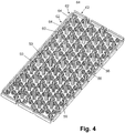
- Fig. 4 shows a perspective view of a plurality of surface elements 50 of the ventilation device 10 of FIG Fig. 1 in a second position to provide air outlet openings.
- Fig. 4 shows a composite of surface elements 50 or a so-called "hexagon mat".
- This hexagon mat consists of a multiplicity of surface elements 50 which are connected to one another via the connecting elements 56.
- Such a mat is manufactured in an injection molding process. Therefore, the mat can be easily and inexpensively produced in large quantities.
- the surface elements 52 and 62 can also be formed at the same time, so that the surface elements 50 have their hard, inflexible surface elements.
- Fig. 4 shows that the hexagon mat is rectangular, with edges 64 arranged on each side of the rectangle above the surface elements 62.
- the hexagon mat can be pulled apart or pressed together by means of adjusting means over the edges 64. In this case, either the surface elements 50 are moved away from one another, which are still held together by the flexible connecting elements 56, or are pressed together again, a distance between the surface elements 50 being closed.
- Fig. 4 shows the second state in which the surface elements 50 are spaced apart. This can also be seen from the gaps between the edges 64. In order to achieve such a deformation of the hexagon mat, the mat must be pulled apart in both the longitudinal and transverse directions.
- the ventilation device 10 in each case has opposing lamellae 40, which are connected to the edges 64 are connected and are pivotally mounted.
- Fig. 5 shows a top view of a carrier plate 30 of the ventilation device 10 of FIG Fig. 1 .
- Fig. 5 shows the view of the carrier plate 30 starting from the surface elements 50.
- the carrier plate 30 has a multiplicity of openings 32.
- the pins 60 of the second flexible elements 58 of the surface elements 50 are inserted into the openings 32.
- the surface elements 50 have a defined distance from the carrier plate 30 above and above the strips 59.
- the carrier plate 30 can, for example, assume a three-dimensional shape, the flexible configuration of the second flexible elements 58, the base 51 and the connecting elements 56 of the surface elements 50 following the contour of the carrier plate 30.
- a closed, relatively hard surface is provided over surface elements 52 and 62.
- Fresh air or conditioned air reaches the surface elements 50 via the openings 34, which are arranged spaced apart from one another in the second position, so that a diffuse air flow can escape therebetween.
- the openings 34 are supplied with fresh air or conditioned air via the connection 16 of the lower housing part 14.
- Fig. 6 shows a rear view of the carrier plate 30 of FIG Fig. 5 .
- the carrier plate 30 has strips 36 on its rear side. The strips 36 can give the carrier plate 30 increased stability.
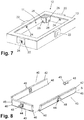
- Fig. 7 shows a perspective view of a housing part of the ventilation device 10 of FIG Fig. 1 .
- the frame has openings 24 in the opposite regions of the projections 22. Threaded portions of the screws 48 protrude into the interior via the openings 24 and are connected to the lamellae 40 (see Fig. 8 ) coupled.
- the lamellae 40 are pivotably supported by pins 46 in openings 28 in walls 26.
- the walls 26 are arranged on the inner walls of the frame.
- Fig. 8 shows a perspective view of setting means for moving the surface elements 50 of the ventilation device 10 of FIG Fig. 1 .
- the slats 40 are pivotally received in the openings 28 of the walls 26 via the journals 46.
- the slats 40 furthermore have a groove 42 which extends along the slats 40 on their upper side.
- the edges 64 of the surface elements 62 are received in the groove 42.
- the surface elements 50 are therefore moved apart or compressed over the edges 64 of the surface elements 62.
- the slats 40 are pivoted about the pivot axis S, which runs through the bearing pins 46.
- the slats 40 also have a receptacle 44 in which a nut 49 is received.
- the nut 49 is received within the receptacle 44 and can therefore not be moved out of the receptacle 44.
- the receptacle 44 accordingly has openings for the screw 48.
- the screw 48 and the nut 49 have a corresponding thread, so that a turning of the nut 48 leads to a pivoting of the slats 40.
- the surface elements 50 are thus moved towards or away from each other.
- Fig. 8 shows only a pair of opposite slats 40 and a single slat 40, the opposite slat 40 of which is not shown. For reasons of clarity, this lamella 40 is not shown in order to illustrate the formation of the screw 48 with the nut 49.
- Fig. 9 shows a top view of the ventilation device 10 in a first position, in which the surface elements 50 provide a closed surface.
- Fig. 10 shows a plan view of the ventilation device 10 in the second position, in which the surface elements 50 are arranged spaced apart from one another to form air outlet openings.
- the surface elements 50 lie directly against one another. Therefore, no air can escape through the air outlet opening 11. If ventilation is to be achieved via the air outlet opening 11, the slats 40 are pivoted, which leads to the surface elements 50 being pulled apart. The composite of surface elements 50 or the hexagon mat is not damaged by the flexible connecting elements 56. In addition, a tension is maintained between the surface elements 50, so that they cannot simply be shifted from their position that has now been taken up. If the slats 40 are moved back to close the air outlet opening, the flexible connecting elements 56 support due to their elasticity Training the merging of the surface elements 50 and thus the closing of the air outlet opening 11th
- lighting devices can be provided which illuminate the space behind the surface elements 50. In the closed position of the surface elements 50, no light penetrates outside, provided that the surface elements 50 are not transparent. If, however, the surface elements 50 are moved away from one another, the air outlet gaps formed between the surface elements 50 can be illuminated in accordance with the pattern and design of the surface elements 50.
- the surface elements of the ventilation device 10 have a hexagonal shape in this exemplary embodiment. Only the surface elements 50 at the edge have a different shape, the contact areas corresponding to the hexagonal Shape of the other surface elements 50 are formed. Instead of such a honeycomb structure, other structures can also be produced.
- Fig. 11 shows a section through the ventilation device 10 in the first position of the surface elements 50.
- the slats 40 are also in a first position.
- the edges 64 are received in the groove 42.
- the surface elements 50 lie directly against one another and thus provide a closed surface.
- Fig. 12 shows a section through the ventilation device 10 in the second position of the surface elements 50.
- the screw 48 is turned in the direction of the arrow. This leads to a displacement of the nut 49 in the receptacle 44 of the lamella 40 along the direction of the arrow.
- nut 49 is therefore displaced to the left or to the right in the drawing direction. If the nut 49 is shifted to the right, this leads to a pivoting of the lamella 40 about the pivot axis S, as indicated by the arrow.
- the air outlet opening 11 is opened via the surface elements 50, in the illustration of FIG Fig. 12 a swivel to the right.
- the edges 64 of the surface elements 62, which are connected to surface elements 50, are likewise displaced to the right via the groove 42. This leads to the surface elements 50 being pulled apart, so that a distance A is provided between the adjacent surface elements 50. Air supplied via connection 16 can then escape via this distance.
- the slats 40 are pivoted and the surface elements 50 are pulled apart or compressed.
- the flexible connecting elements 56 enable such a displacement of the surface elements 50 relative to one another without causing damage.
- the flexible connecting elements 56 support a contraction of the surface elements 50.
- a ventilation device 10 with such a combination of surface elements 50 or such a hexagon mat is simple to manufacture and enables adaptation to different surfaces.
- the provision of a hexagon mat in an injection molding process allows it to be produced inexpensively in large quantities, without having to resort to additive manufacturing processes.
Landscapes
- Engineering & Computer Science (AREA)
- Mechanical Engineering (AREA)
- Chemical & Material Sciences (AREA)
- Combustion & Propulsion (AREA)
- General Engineering & Computer Science (AREA)
- Physics & Mathematics (AREA)
- Thermal Sciences (AREA)
- Air-Flow Control Members (AREA)
- Injection Moulding Of Plastics Or The Like (AREA)
Claims (10)
- Dispositif d'aération, présentant des éléments plans (50), qui s'appliquent les uns contre les autres dans une première position afin de présenter une surface fermée, et sont agencés espacés les uns des autres dans une seconde position afin de former des ouvertures de sortie d'air, caractérisé en ce que- les éléments plans (50) sont reliés les uns aux autres par le biais d'éléments de liaison souples (56),- les éléments plans (50) agencés au niveau des bords, sont reliés à des moyens de réglage, et- les moyens de réglage sont réalisés mobiles et agencés de sorte que tous les éléments plans (50) peuvent être amenés dans la seconde position par le biais des moyens de réglage.
- Dispositif d'aération selon la revendication 1, dans lequel les éléments plans (50) présentent au niveau de leur face arrière, opposée à la surface, deux éléments souples (58), qui sont reliés à une plaque de support (30).
- Dispositif d'aération selon la revendication 2, dans lequel la plaque de support (30) présente des premières ouvertures (32) pour les seconds éléments souples (58) et des secondes ouvertures (34) pour l'air traversant.
- Dispositif d'aération selon l'une quelconque des revendications 1 à 3, dans lequel les moyens de réglage présentent des lamelles logées de manière pivotante (40) ou des baguettes logées de manière coulissante, qui sont déplaçables par le biais de dispositifs d'entraînement.
- Dispositif d'aération selon la revendication 4, dans lequel les dispositifs d'entraînement peuvent être entraînés manuellement ou par moteur.
- Dispositif d'aération selon l'une quelconque des revendications 1 à 5, dans lequel les éléments plans (50) présentent au niveau de leur face tournée vers la surface un élément de surface (52 ; 62) plus dur que les éléments de liaison souples (56).
- Dispositif d'aération selon l'une quelconque des revendications 1 à 6, dans lequel les éléments plans (50) avec les éléments de liaison (56) et/ou les seconds éléments souples (58) sont fabriqués dans un procédé de moulage par injection.
- Dispositif d'aération selon la revendication 6, dans lequel les éléments de surface (52 ; 62) sont montés sur les éléments plans (50) dans un procédé de moulage par injection à 2 composants, au moyen d'un adhésif ou par apport de chaleur.
- Dispositif d'aération selon l'une quelconque des revendications 1 à 8, présentant au moins un dispositif d'éclairage, lequel est agencé derrière ou sous les éléments plans (50).
- Dispositif d'aération selon l'une quelconque des revendications 1 à 9, dans lequel les éléments plans (50) présentent une forme hexagonale, rectangulaire et/ou polygonale.
Applications Claiming Priority (1)
| Application Number | Priority Date | Filing Date | Title |
|---|---|---|---|
| DE102017118229.2A DE102017118229B4 (de) | 2017-08-10 | 2017-08-10 | Belüftungseinrichtung |
Publications (2)
| Publication Number | Publication Date |
|---|---|
| EP3441245A1 EP3441245A1 (fr) | 2019-02-13 |
| EP3441245B1 true EP3441245B1 (fr) | 2020-03-18 |
Family
ID=59929805
Family Applications (1)
| Application Number | Title | Priority Date | Filing Date |
|---|---|---|---|
| EP18187260.7A Active EP3441245B1 (fr) | 2017-08-10 | 2018-08-03 | Dispositif d'aération |
Country Status (2)
| Country | Link |
|---|---|
| EP (1) | EP3441245B1 (fr) |
| DE (1) | DE102017118229B4 (fr) |
Families Citing this family (3)
| Publication number | Priority date | Publication date | Assignee | Title |
|---|---|---|---|---|
| DE102018100851A1 (de) * | 2018-01-16 | 2019-07-18 | Fischer Automotive Systems Gmbh & Co. Kg | Licht- und/oder Luftaustrittsöffnung für einen Fahrgastraum eines Fahrzeugs |
| DE202019104255U1 (de) | 2019-08-02 | 2019-08-13 | Dr. Schneider Kunststoffwerke Gmbh | Belüftungseinrichtung |
| DE102020103630B4 (de) | 2020-02-12 | 2023-12-21 | Audi Aktiengesellschaft | Luftausströmvorrichtung für ein Fahrzeug |
Family Cites Families (5)
| Publication number | Priority date | Publication date | Assignee | Title |
|---|---|---|---|---|
| GB2346960A (en) * | 1999-02-16 | 2000-08-23 | Rover Group | An air flow control arrangement |
| JP2004203176A (ja) * | 2002-12-25 | 2004-07-22 | Toyoda Gosei Co Ltd | 空調用レジスタ |
| DE10303114B3 (de) * | 2003-01-27 | 2004-08-05 | Sai Automotive Sal Gmbh | Ausströmer für ein Fahrzeug |
| DE102011003435B4 (de) | 2011-02-01 | 2016-05-04 | Lisa Dräxlmaier GmbH | Belüftungssystem |
| US9341386B2 (en) | 2012-10-23 | 2016-05-17 | GM Global Technology Operations LLC | Vehicular airflow outlet |
-
2017
- 2017-08-10 DE DE102017118229.2A patent/DE102017118229B4/de not_active Expired - Fee Related
-
2018
- 2018-08-03 EP EP18187260.7A patent/EP3441245B1/fr active Active
Non-Patent Citations (1)
| Title |
|---|
| None * |
Also Published As
| Publication number | Publication date |
|---|---|
| DE102017118229B4 (de) | 2018-08-09 |
| EP3441245A1 (fr) | 2019-02-13 |
| DE102017118229A1 (de) | 2017-10-12 |
Similar Documents
| Publication | Publication Date | Title |
|---|---|---|
| EP3192684B1 (fr) | Dispositif de déplacement de lamelles d'un diffuseur d'air | |
| EP3027443B1 (fr) | Élément de guidage d'air | |
| EP3530506B1 (fr) | Dispositif d'écoulement d'air | |
| EP2266824B1 (fr) | Elément de débit d'air | |
| EP3441245B1 (fr) | Dispositif d'aération | |
| EP1497147B1 (fr) | Systeme de ventilation | |
| EP3321113B1 (fr) | Dispositif d'écoulement d'air | |
| EP3381725B1 (fr) | Aérateur | |
| EP3530505B1 (fr) | Dispositif d'écoulement d'air | |
| EP3762245A1 (fr) | Diffuseur d'air, module et ensemble formant diffuseur d'air | |
| EP1270286B1 (fr) | Dispositif pour diriger l'air, notamment pour un véhicule | |
| WO2016020171A1 (fr) | Dispositif de ventilation | |
| DE102019132921B4 (de) | Luftausströmer mit Bedieneinrichtung | |
| DE102010014075A1 (de) | Belüftungsdüse für den Innenraum eines Kraftfahrzeugs | |
| DE19816013B4 (de) | Luftstromverteiler für einen Kraftfahrzeuginnenraum | |
| DE60222256T2 (de) | Vorrichtung zur mechanischen betätigung von elementen für die belüftung eines fahrzeugs | |
| DE102018127505B4 (de) | Luftausströmer mit Bedieneinrichtung | |
| EP3471979A1 (fr) | Diffuseur d'air | |
| DE102011003433B4 (de) | Ausströmer und Belüftungssystem | |
| EP3553626A1 (fr) | Dispositif de commande | |
| DE102016010653B4 (de) | Stellvorrichtung, Kraftfahrzeug mit einer Stellvorrichtung und Verfahren zum Betreiben einer Stellvorrichtung | |
| DE102022206301A1 (de) | Fahrzeuglüftungsvorrichtung mit flexiblen Flügel | |
| DE102024119607A1 (de) | Luftausströmer für eine Belüftungseinrichtung eines Kraftfahrzeugs |
Legal Events
| Date | Code | Title | Description |
|---|---|---|---|
| PUAI | Public reference made under article 153(3) epc to a published international application that has entered the european phase |
Free format text: ORIGINAL CODE: 0009012 |
|
| STAA | Information on the status of an ep patent application or granted ep patent |
Free format text: STATUS: THE APPLICATION HAS BEEN PUBLISHED |
|
| AK | Designated contracting states |
Kind code of ref document: A1 Designated state(s): AL AT BE BG CH CY CZ DE DK EE ES FI FR GB GR HR HU IE IS IT LI LT LU LV MC MK MT NL NO PL PT RO RS SE SI SK SM TR |
|
| AX | Request for extension of the european patent |
Extension state: BA ME |
|
| STAA | Information on the status of an ep patent application or granted ep patent |
Free format text: STATUS: REQUEST FOR EXAMINATION WAS MADE |
|
| 17P | Request for examination filed |
Effective date: 20190219 |
|
| RBV | Designated contracting states (corrected) |
Designated state(s): AL AT BE BG CH CY CZ DE DK EE ES FI FR GB GR HR HU IE IS IT LI LT LU LV MC MK MT NL NO PL PT RO RS SE SI SK SM TR |
|
| GRAP | Despatch of communication of intention to grant a patent |
Free format text: ORIGINAL CODE: EPIDOSNIGR1 |
|
| STAA | Information on the status of an ep patent application or granted ep patent |
Free format text: STATUS: GRANT OF PATENT IS INTENDED |
|
| RIC1 | Information provided on ipc code assigned before grant |
Ipc: F24F 13/06 20060101ALI20191128BHEP Ipc: B60H 1/34 20060101AFI20191128BHEP Ipc: F24F 13/078 20060101ALI20191128BHEP |
|
| INTG | Intention to grant announced |
Effective date: 20191217 |
|
| GRAS | Grant fee paid |
Free format text: ORIGINAL CODE: EPIDOSNIGR3 |
|
| GRAA | (expected) grant |
Free format text: ORIGINAL CODE: 0009210 |
|
| STAA | Information on the status of an ep patent application or granted ep patent |
Free format text: STATUS: THE PATENT HAS BEEN GRANTED |
|
| AK | Designated contracting states |
Kind code of ref document: B1 Designated state(s): AL AT BE BG CH CY CZ DE DK EE ES FI FR GB GR HR HU IE IS IT LI LT LU LV MC MK MT NL NO PL PT RO RS SE SI SK SM TR |
|
| REG | Reference to a national code |
Ref country code: GB Ref legal event code: FG4D Free format text: NOT ENGLISH |
|
| REG | Reference to a national code |
Ref country code: DE Ref legal event code: R096 Ref document number: 502018000975 Country of ref document: DE |
|
| REG | Reference to a national code |
Ref country code: AT Ref legal event code: REF Ref document number: 1245516 Country of ref document: AT Kind code of ref document: T Effective date: 20200415 Ref country code: IE Ref legal event code: FG4D Free format text: LANGUAGE OF EP DOCUMENT: GERMAN |
|
| REG | Reference to a national code |
Ref country code: SE Ref legal event code: TRGR |
|
| PG25 | Lapsed in a contracting state [announced via postgrant information from national office to epo] |
Ref country code: NO Free format text: LAPSE BECAUSE OF FAILURE TO SUBMIT A TRANSLATION OF THE DESCRIPTION OR TO PAY THE FEE WITHIN THE PRESCRIBED TIME-LIMIT Effective date: 20200618 Ref country code: RS Free format text: LAPSE BECAUSE OF FAILURE TO SUBMIT A TRANSLATION OF THE DESCRIPTION OR TO PAY THE FEE WITHIN THE PRESCRIBED TIME-LIMIT Effective date: 20200318 Ref country code: FI Free format text: LAPSE BECAUSE OF FAILURE TO SUBMIT A TRANSLATION OF THE DESCRIPTION OR TO PAY THE FEE WITHIN THE PRESCRIBED TIME-LIMIT Effective date: 20200318 |
|
| REG | Reference to a national code |
Ref country code: NL Ref legal event code: MP Effective date: 20200318 |
|
| PG25 | Lapsed in a contracting state [announced via postgrant information from national office to epo] |
Ref country code: GR Free format text: LAPSE BECAUSE OF FAILURE TO SUBMIT A TRANSLATION OF THE DESCRIPTION OR TO PAY THE FEE WITHIN THE PRESCRIBED TIME-LIMIT Effective date: 20200619 Ref country code: BG Free format text: LAPSE BECAUSE OF FAILURE TO SUBMIT A TRANSLATION OF THE DESCRIPTION OR TO PAY THE FEE WITHIN THE PRESCRIBED TIME-LIMIT Effective date: 20200618 Ref country code: HR Free format text: LAPSE BECAUSE OF FAILURE TO SUBMIT A TRANSLATION OF THE DESCRIPTION OR TO PAY THE FEE WITHIN THE PRESCRIBED TIME-LIMIT Effective date: 20200318 Ref country code: LV Free format text: LAPSE BECAUSE OF FAILURE TO SUBMIT A TRANSLATION OF THE DESCRIPTION OR TO PAY THE FEE WITHIN THE PRESCRIBED TIME-LIMIT Effective date: 20200318 |
|
| REG | Reference to a national code |
Ref country code: LT Ref legal event code: MG4D |
|
| PG25 | Lapsed in a contracting state [announced via postgrant information from national office to epo] |
Ref country code: NL Free format text: LAPSE BECAUSE OF FAILURE TO SUBMIT A TRANSLATION OF THE DESCRIPTION OR TO PAY THE FEE WITHIN THE PRESCRIBED TIME-LIMIT Effective date: 20200318 |
|
| PG25 | Lapsed in a contracting state [announced via postgrant information from national office to epo] |
Ref country code: CZ Free format text: LAPSE BECAUSE OF FAILURE TO SUBMIT A TRANSLATION OF THE DESCRIPTION OR TO PAY THE FEE WITHIN THE PRESCRIBED TIME-LIMIT Effective date: 20200318 Ref country code: RO Free format text: LAPSE BECAUSE OF FAILURE TO SUBMIT A TRANSLATION OF THE DESCRIPTION OR TO PAY THE FEE WITHIN THE PRESCRIBED TIME-LIMIT Effective date: 20200318 Ref country code: EE Free format text: LAPSE BECAUSE OF FAILURE TO SUBMIT A TRANSLATION OF THE DESCRIPTION OR TO PAY THE FEE WITHIN THE PRESCRIBED TIME-LIMIT Effective date: 20200318 Ref country code: PT Free format text: LAPSE BECAUSE OF FAILURE TO SUBMIT A TRANSLATION OF THE DESCRIPTION OR TO PAY THE FEE WITHIN THE PRESCRIBED TIME-LIMIT Effective date: 20200812 Ref country code: SM Free format text: LAPSE BECAUSE OF FAILURE TO SUBMIT A TRANSLATION OF THE DESCRIPTION OR TO PAY THE FEE WITHIN THE PRESCRIBED TIME-LIMIT Effective date: 20200318 Ref country code: LT Free format text: LAPSE BECAUSE OF FAILURE TO SUBMIT A TRANSLATION OF THE DESCRIPTION OR TO PAY THE FEE WITHIN THE PRESCRIBED TIME-LIMIT Effective date: 20200318 Ref country code: IS Free format text: LAPSE BECAUSE OF FAILURE TO SUBMIT A TRANSLATION OF THE DESCRIPTION OR TO PAY THE FEE WITHIN THE PRESCRIBED TIME-LIMIT Effective date: 20200718 Ref country code: SK Free format text: LAPSE BECAUSE OF FAILURE TO SUBMIT A TRANSLATION OF THE DESCRIPTION OR TO PAY THE FEE WITHIN THE PRESCRIBED TIME-LIMIT Effective date: 20200318 |
|
| REG | Reference to a national code |
Ref country code: DE Ref legal event code: R097 Ref document number: 502018000975 Country of ref document: DE |
|
| PLBE | No opposition filed within time limit |
Free format text: ORIGINAL CODE: 0009261 |
|
| STAA | Information on the status of an ep patent application or granted ep patent |
Free format text: STATUS: NO OPPOSITION FILED WITHIN TIME LIMIT |
|
| PG25 | Lapsed in a contracting state [announced via postgrant information from national office to epo] |
Ref country code: DK Free format text: LAPSE BECAUSE OF FAILURE TO SUBMIT A TRANSLATION OF THE DESCRIPTION OR TO PAY THE FEE WITHIN THE PRESCRIBED TIME-LIMIT Effective date: 20200318 Ref country code: IT Free format text: LAPSE BECAUSE OF FAILURE TO SUBMIT A TRANSLATION OF THE DESCRIPTION OR TO PAY THE FEE WITHIN THE PRESCRIBED TIME-LIMIT Effective date: 20200318 Ref country code: ES Free format text: LAPSE BECAUSE OF FAILURE TO SUBMIT A TRANSLATION OF THE DESCRIPTION OR TO PAY THE FEE WITHIN THE PRESCRIBED TIME-LIMIT Effective date: 20200318 |
|
| 26N | No opposition filed |
Effective date: 20201221 |
|
| PG25 | Lapsed in a contracting state [announced via postgrant information from national office to epo] |
Ref country code: PL Free format text: LAPSE BECAUSE OF FAILURE TO SUBMIT A TRANSLATION OF THE DESCRIPTION OR TO PAY THE FEE WITHIN THE PRESCRIBED TIME-LIMIT Effective date: 20200318 |
|
| PG25 | Lapsed in a contracting state [announced via postgrant information from national office to epo] |
Ref country code: MC Free format text: LAPSE BECAUSE OF FAILURE TO SUBMIT A TRANSLATION OF THE DESCRIPTION OR TO PAY THE FEE WITHIN THE PRESCRIBED TIME-LIMIT Effective date: 20200318 |
|
| PG25 | Lapsed in a contracting state [announced via postgrant information from national office to epo] |
Ref country code: LU Free format text: LAPSE BECAUSE OF NON-PAYMENT OF DUE FEES Effective date: 20200803 |
|
| REG | Reference to a national code |
Ref country code: BE Ref legal event code: MM Effective date: 20200831 |
|
| PG25 | Lapsed in a contracting state [announced via postgrant information from national office to epo] |
Ref country code: SI Free format text: LAPSE BECAUSE OF FAILURE TO SUBMIT A TRANSLATION OF THE DESCRIPTION OR TO PAY THE FEE WITHIN THE PRESCRIBED TIME-LIMIT Effective date: 20200318 |
|
| PG25 | Lapsed in a contracting state [announced via postgrant information from national office to epo] |
Ref country code: BE Free format text: LAPSE BECAUSE OF NON-PAYMENT OF DUE FEES Effective date: 20200831 Ref country code: IE Free format text: LAPSE BECAUSE OF NON-PAYMENT OF DUE FEES Effective date: 20200803 |
|
| REG | Reference to a national code |
Ref country code: CH Ref legal event code: PL |
|
| PG25 | Lapsed in a contracting state [announced via postgrant information from national office to epo] |
Ref country code: LI Free format text: LAPSE BECAUSE OF NON-PAYMENT OF DUE FEES Effective date: 20210831 Ref country code: CH Free format text: LAPSE BECAUSE OF NON-PAYMENT OF DUE FEES Effective date: 20210831 |
|
| PG25 | Lapsed in a contracting state [announced via postgrant information from national office to epo] |
Ref country code: TR Free format text: LAPSE BECAUSE OF FAILURE TO SUBMIT A TRANSLATION OF THE DESCRIPTION OR TO PAY THE FEE WITHIN THE PRESCRIBED TIME-LIMIT Effective date: 20200318 Ref country code: MT Free format text: LAPSE BECAUSE OF FAILURE TO SUBMIT A TRANSLATION OF THE DESCRIPTION OR TO PAY THE FEE WITHIN THE PRESCRIBED TIME-LIMIT Effective date: 20200318 Ref country code: CY Free format text: LAPSE BECAUSE OF FAILURE TO SUBMIT A TRANSLATION OF THE DESCRIPTION OR TO PAY THE FEE WITHIN THE PRESCRIBED TIME-LIMIT Effective date: 20200318 |
|
| PG25 | Lapsed in a contracting state [announced via postgrant information from national office to epo] |
Ref country code: MK Free format text: LAPSE BECAUSE OF FAILURE TO SUBMIT A TRANSLATION OF THE DESCRIPTION OR TO PAY THE FEE WITHIN THE PRESCRIBED TIME-LIMIT Effective date: 20200318 Ref country code: AL Free format text: LAPSE BECAUSE OF FAILURE TO SUBMIT A TRANSLATION OF THE DESCRIPTION OR TO PAY THE FEE WITHIN THE PRESCRIBED TIME-LIMIT Effective date: 20200318 |
|
| P01 | Opt-out of the competence of the unified patent court (upc) registered |
Effective date: 20230525 |
|
| REG | Reference to a national code |
Ref country code: AT Ref legal event code: MM01 Ref document number: 1245516 Country of ref document: AT Kind code of ref document: T Effective date: 20230803 |
|
| PG25 | Lapsed in a contracting state [announced via postgrant information from national office to epo] |
Ref country code: AT Free format text: LAPSE BECAUSE OF NON-PAYMENT OF DUE FEES Effective date: 20230803 |
|
| PG25 | Lapsed in a contracting state [announced via postgrant information from national office to epo] |
Ref country code: AT Free format text: LAPSE BECAUSE OF NON-PAYMENT OF DUE FEES Effective date: 20230803 |
|
| PGFP | Annual fee paid to national office [announced via postgrant information from national office to epo] |
Ref country code: SE Payment date: 20240823 Year of fee payment: 7 |
|
| REG | Reference to a national code |
Ref country code: DE Ref legal event code: R081 Ref document number: 502018000975 Country of ref document: DE Owner name: MOTHERSON DRSC DEUTSCHLAND GMBH, DE Free format text: FORMER OWNER: DR. SCHNEIDER KUNSTSTOFFWERKE GMBH, 96317 KRONACH, DE |
|
| REG | Reference to a national code |
Ref country code: GB Ref legal event code: 732E Free format text: REGISTERED BETWEEN 20250724 AND 20250730 |
|
| PGFP | Annual fee paid to national office [announced via postgrant information from national office to epo] |
Ref country code: DE Payment date: 20250226 Year of fee payment: 8 |
|
| PGFP | Annual fee paid to national office [announced via postgrant information from national office to epo] |
Ref country code: GB Payment date: 20250822 Year of fee payment: 8 |
|
| PGFP | Annual fee paid to national office [announced via postgrant information from national office to epo] |
Ref country code: FR Payment date: 20250821 Year of fee payment: 8 |
|
| PGFP | Annual fee paid to national office [announced via postgrant information from national office to epo] |
Ref country code: AT Payment date: 20260410 Year of fee payment: 5 |