EP3441211B1 - Method for producing a series of containers comprising a step of marking the containers - Google Patents
Method for producing a series of containers comprising a step of marking the containers Download PDFInfo
- Publication number
- EP3441211B1 EP3441211B1 EP18305982.3A EP18305982A EP3441211B1 EP 3441211 B1 EP3441211 B1 EP 3441211B1 EP 18305982 A EP18305982 A EP 18305982A EP 3441211 B1 EP3441211 B1 EP 3441211B1
- Authority
- EP
- European Patent Office
- Prior art keywords
- container
- marking
- station
- identified
- containers
- Prior art date
- Legal status (The legal status is an assumption and is not a legal conclusion. Google has not performed a legal analysis and makes no representation as to the accuracy of the status listed.)
- Active
Links
Images
Classifications
-
- B—PERFORMING OPERATIONS; TRANSPORTING
- B65—CONVEYING; PACKING; STORING; HANDLING THIN OR FILAMENTARY MATERIAL
- B65B—MACHINES, APPARATUS OR DEVICES FOR, OR METHODS OF, PACKAGING ARTICLES OR MATERIALS; UNPACKING
- B65B61/00—Auxiliary devices, not otherwise provided for, for operating on sheets, blanks, webs, binding material, containers or packages
- B65B61/02—Auxiliary devices, not otherwise provided for, for operating on sheets, blanks, webs, binding material, containers or packages for perforating, scoring, slitting, or applying code or date marks on material prior to packaging
- B65B61/025—Auxiliary devices, not otherwise provided for, for operating on sheets, blanks, webs, binding material, containers or packages for perforating, scoring, slitting, or applying code or date marks on material prior to packaging for applying, e.g. printing, code or date marks on material prior to packaging
-
- B—PERFORMING OPERATIONS; TRANSPORTING
- B29—WORKING OF PLASTICS; WORKING OF SUBSTANCES IN A PLASTIC STATE IN GENERAL
- B29C—SHAPING OR JOINING OF PLASTICS; SHAPING OF MATERIAL IN A PLASTIC STATE, NOT OTHERWISE PROVIDED FOR; AFTER-TREATMENT OF THE SHAPED PRODUCTS, e.g. REPAIRING
- B29C49/00—Blow-moulding, i.e. blowing a preform or parison to a desired shape within a mould; Apparatus therefor
- B29C49/24—Lining or labelling
-
- B—PERFORMING OPERATIONS; TRANSPORTING
- B29—WORKING OF PLASTICS; WORKING OF SUBSTANCES IN A PLASTIC STATE IN GENERAL
- B29C—SHAPING OR JOINING OF PLASTICS; SHAPING OF MATERIAL IN A PLASTIC STATE, NOT OTHERWISE PROVIDED FOR; AFTER-TREATMENT OF THE SHAPED PRODUCTS, e.g. REPAIRING
- B29C49/00—Blow-moulding, i.e. blowing a preform or parison to a desired shape within a mould; Apparatus therefor
- B29C49/42—Component parts, details or accessories; Auxiliary operations
- B29C49/46—Component parts, details or accessories; Auxiliary operations characterised by using particular environment or blow fluids other than air
-
- B—PERFORMING OPERATIONS; TRANSPORTING
- B29—WORKING OF PLASTICS; WORKING OF SUBSTANCES IN A PLASTIC STATE IN GENERAL
- B29C—SHAPING OR JOINING OF PLASTICS; SHAPING OF MATERIAL IN A PLASTIC STATE, NOT OTHERWISE PROVIDED FOR; AFTER-TREATMENT OF THE SHAPED PRODUCTS, e.g. REPAIRING
- B29C49/00—Blow-moulding, i.e. blowing a preform or parison to a desired shape within a mould; Apparatus therefor
- B29C49/42—Component parts, details or accessories; Auxiliary operations
- B29C49/64—Heating or cooling preforms, parisons or blown articles
- B29C49/6409—Thermal conditioning of preforms
- B29C49/6418—Heating of preforms
-
- B—PERFORMING OPERATIONS; TRANSPORTING
- B29—WORKING OF PLASTICS; WORKING OF SUBSTANCES IN A PLASTIC STATE IN GENERAL
- B29C—SHAPING OR JOINING OF PLASTICS; SHAPING OF MATERIAL IN A PLASTIC STATE, NOT OTHERWISE PROVIDED FOR; AFTER-TREATMENT OF THE SHAPED PRODUCTS, e.g. REPAIRING
- B29C49/00—Blow-moulding, i.e. blowing a preform or parison to a desired shape within a mould; Apparatus therefor
- B29C49/42—Component parts, details or accessories; Auxiliary operations
- B29C49/78—Measuring, controlling or regulating
-
- B—PERFORMING OPERATIONS; TRANSPORTING
- B29—WORKING OF PLASTICS; WORKING OF SUBSTANCES IN A PLASTIC STATE IN GENERAL
- B29D—PRODUCING PARTICULAR ARTICLES FROM PLASTICS OR FROM SUBSTANCES IN A PLASTIC STATE
- B29D22/00—Producing hollow articles
- B29D22/003—Containers for packaging, storing or transporting, e.g. bottles, jars, cans, barrels, tanks
-
- B—PERFORMING OPERATIONS; TRANSPORTING
- B41—PRINTING; LINING MACHINES; TYPEWRITERS; STAMPS
- B41J—TYPEWRITERS; SELECTIVE PRINTING MECHANISMS, i.e. MECHANISMS PRINTING OTHERWISE THAN FROM A FORME; CORRECTION OF TYPOGRAPHICAL ERRORS
- B41J3/00—Typewriters or selective printing or marking mechanisms characterised by the purpose for which they are constructed
- B41J3/407—Typewriters or selective printing or marking mechanisms characterised by the purpose for which they are constructed for marking on special material
-
- B—PERFORMING OPERATIONS; TRANSPORTING
- B41—PRINTING; LINING MACHINES; TYPEWRITERS; STAMPS
- B41J—TYPEWRITERS; SELECTIVE PRINTING MECHANISMS, i.e. MECHANISMS PRINTING OTHERWISE THAN FROM A FORME; CORRECTION OF TYPOGRAPHICAL ERRORS
- B41J3/00—Typewriters or selective printing or marking mechanisms characterised by the purpose for which they are constructed
- B41J3/44—Typewriters or selective printing mechanisms having dual functions or combined with, or coupled to, apparatus performing other functions
-
- B—PERFORMING OPERATIONS; TRANSPORTING
- B65—CONVEYING; PACKING; STORING; HANDLING THIN OR FILAMENTARY MATERIAL
- B65B—MACHINES, APPARATUS OR DEVICES FOR, OR METHODS OF, PACKAGING ARTICLES OR MATERIALS; UNPACKING
- B65B3/00—Packaging plastic material, semiliquids, liquids or mixed solids and liquids, in individual containers or receptacles, e.g. bags, sacks, boxes, cartons, cans, or jars
- B65B3/003—Filling medical containers such as ampoules, vials, syringes or the like
-
- B—PERFORMING OPERATIONS; TRANSPORTING
- B65—CONVEYING; PACKING; STORING; HANDLING THIN OR FILAMENTARY MATERIAL
- B65B—MACHINES, APPARATUS OR DEVICES FOR, OR METHODS OF, PACKAGING ARTICLES OR MATERIALS; UNPACKING
- B65B43/00—Forming, feeding, opening or setting-up containers or receptacles in association with packaging
- B65B43/42—Feeding or positioning bags, boxes, or cartons in the distended, opened, or set-up state; Feeding preformed rigid containers, e.g. tins, capsules, glass tubes, glasses, to the packaging position; Locating containers or receptacles at the filling position; Supporting containers or receptacles during the filling operation
- B65B43/46—Feeding or positioning bags, boxes, or cartons in the distended, opened, or set-up state; Feeding preformed rigid containers, e.g. tins, capsules, glass tubes, glasses, to the packaging position; Locating containers or receptacles at the filling position; Supporting containers or receptacles during the filling operation using grippers
-
- B—PERFORMING OPERATIONS; TRANSPORTING
- B65—CONVEYING; PACKING; STORING; HANDLING THIN OR FILAMENTARY MATERIAL
- B65B—MACHINES, APPARATUS OR DEVICES FOR, OR METHODS OF, PACKAGING ARTICLES OR MATERIALS; UNPACKING
- B65B43/00—Forming, feeding, opening or setting-up containers or receptacles in association with packaging
- B65B43/42—Feeding or positioning bags, boxes, or cartons in the distended, opened, or set-up state; Feeding preformed rigid containers, e.g. tins, capsules, glass tubes, glasses, to the packaging position; Locating containers or receptacles at the filling position; Supporting containers or receptacles during the filling operation
- B65B43/54—Means for supporting containers or receptacles during the filling operation
-
- B—PERFORMING OPERATIONS; TRANSPORTING
- B65—CONVEYING; PACKING; STORING; HANDLING THIN OR FILAMENTARY MATERIAL
- B65B—MACHINES, APPARATUS OR DEVICES FOR, OR METHODS OF, PACKAGING ARTICLES OR MATERIALS; UNPACKING
- B65B57/00—Automatic control, checking, warning, or safety devices
- B65B57/10—Automatic control, checking, warning, or safety devices responsive to absence, presence, abnormal feed, or misplacement of articles or materials to be packaged
- B65B57/12—Automatic control, checking, warning, or safety devices responsive to absence, presence, abnormal feed, or misplacement of articles or materials to be packaged and operating to control, or stop, the feed of wrapping materials, containers, or packages
-
- B—PERFORMING OPERATIONS; TRANSPORTING
- B65—CONVEYING; PACKING; STORING; HANDLING THIN OR FILAMENTARY MATERIAL
- B65C—LABELLING OR TAGGING MACHINES, APPARATUS, OR PROCESSES
- B65C3/00—Labelling other than flat surfaces
- B65C3/06—Affixing labels to short rigid containers
-
- B—PERFORMING OPERATIONS; TRANSPORTING
- B67—OPENING, CLOSING OR CLEANING BOTTLES, JARS OR SIMILAR CONTAINERS; LIQUID HANDLING
- B67C—CLEANING, FILLING WITH LIQUIDS OR SEMILIQUIDS, OR EMPTYING, OF BOTTLES, JARS, CANS, CASKS, BARRELS, OR SIMILAR CONTAINERS, NOT OTHERWISE PROVIDED FOR; FUNNELS
- B67C7/00—Concurrent cleaning, filling, and closing of bottles; Processes or devices for at least two of these operations
- B67C7/0006—Conveying; Synchronising
- B67C7/004—Conveying; Synchronising the containers travelling along a circular path
-
- G—PHYSICS
- G05—CONTROLLING; REGULATING
- G05B—CONTROL OR REGULATING SYSTEMS IN GENERAL; FUNCTIONAL ELEMENTS OF SUCH SYSTEMS; MONITORING OR TESTING ARRANGEMENTS FOR SUCH SYSTEMS OR ELEMENTS
- G05B19/00—Program-control systems
- G05B19/02—Program-control systems electric
- G05B19/418—Total factory control, i.e. centrally controlling a plurality of machines, e.g. direct or distributed numerical control [DNC], flexible manufacturing systems [FMS], integrated manufacturing systems [IMS] or computer integrated manufacturing [CIM]
-
- B—PERFORMING OPERATIONS; TRANSPORTING
- B29—WORKING OF PLASTICS; WORKING OF SUBSTANCES IN A PLASTIC STATE IN GENERAL
- B29C—SHAPING OR JOINING OF PLASTICS; SHAPING OF MATERIAL IN A PLASTIC STATE, NOT OTHERWISE PROVIDED FOR; AFTER-TREATMENT OF THE SHAPED PRODUCTS, e.g. REPAIRING
- B29C49/00—Blow-moulding, i.e. blowing a preform or parison to a desired shape within a mould; Apparatus therefor
- B29C49/20—Blow-moulding, i.e. blowing a preform or parison to a desired shape within a mould; Apparatus therefor of articles having inserts or reinforcements ; Handling of inserts or reinforcements
- B29C2049/2021—Inserts characterised by the material or type
- B29C2049/2071—Inserts characterised by the material or type comprising electronic elements or detection means, e.g. chips, RFIDs or barcodes
-
- B—PERFORMING OPERATIONS; TRANSPORTING
- B29—WORKING OF PLASTICS; WORKING OF SUBSTANCES IN A PLASTIC STATE IN GENERAL
- B29C—SHAPING OR JOINING OF PLASTICS; SHAPING OF MATERIAL IN A PLASTIC STATE, NOT OTHERWISE PROVIDED FOR; AFTER-TREATMENT OF THE SHAPED PRODUCTS, e.g. REPAIRING
- B29C49/00—Blow-moulding, i.e. blowing a preform or parison to a desired shape within a mould; Apparatus therefor
- B29C49/24—Lining or labelling
- B29C2049/2404—Lining or labelling inside the article
-
- B—PERFORMING OPERATIONS; TRANSPORTING
- B29—WORKING OF PLASTICS; WORKING OF SUBSTANCES IN A PLASTIC STATE IN GENERAL
- B29C—SHAPING OR JOINING OF PLASTICS; SHAPING OF MATERIAL IN A PLASTIC STATE, NOT OTHERWISE PROVIDED FOR; AFTER-TREATMENT OF THE SHAPED PRODUCTS, e.g. REPAIRING
- B29C49/00—Blow-moulding, i.e. blowing a preform or parison to a desired shape within a mould; Apparatus therefor
- B29C49/42—Component parts, details or accessories; Auxiliary operations
- B29C49/46—Component parts, details or accessories; Auxiliary operations characterised by using particular environment or blow fluids other than air
- B29C2049/4602—Blowing fluids
- B29C2049/465—Blowing fluids being incompressible
- B29C2049/4664—Blowing fluids being incompressible staying in the final article
-
- B—PERFORMING OPERATIONS; TRANSPORTING
- B29—WORKING OF PLASTICS; WORKING OF SUBSTANCES IN A PLASTIC STATE IN GENERAL
- B29C—SHAPING OR JOINING OF PLASTICS; SHAPING OF MATERIAL IN A PLASTIC STATE, NOT OTHERWISE PROVIDED FOR; AFTER-TREATMENT OF THE SHAPED PRODUCTS, e.g. REPAIRING
- B29C2949/00—Indexing scheme relating to blow-moulding
- B29C2949/07—Preforms or parisons characterised by their configuration
- B29C2949/0715—Preforms or parisons characterised by their configuration the preform having one end closed
-
- B—PERFORMING OPERATIONS; TRANSPORTING
- B29—WORKING OF PLASTICS; WORKING OF SUBSTANCES IN A PLASTIC STATE IN GENERAL
- B29C—SHAPING OR JOINING OF PLASTICS; SHAPING OF MATERIAL IN A PLASTIC STATE, NOT OTHERWISE PROVIDED FOR; AFTER-TREATMENT OF THE SHAPED PRODUCTS, e.g. REPAIRING
- B29C2949/00—Indexing scheme relating to blow-moulding
- B29C2949/07—Preforms or parisons characterised by their configuration
- B29C2949/079—Auxiliary parts or inserts
-
- B—PERFORMING OPERATIONS; TRANSPORTING
- B29—WORKING OF PLASTICS; WORKING OF SUBSTANCES IN A PLASTIC STATE IN GENERAL
- B29C—SHAPING OR JOINING OF PLASTICS; SHAPING OF MATERIAL IN A PLASTIC STATE, NOT OTHERWISE PROVIDED FOR; AFTER-TREATMENT OF THE SHAPED PRODUCTS, e.g. REPAIRING
- B29C49/00—Blow-moulding, i.e. blowing a preform or parison to a desired shape within a mould; Apparatus therefor
- B29C49/02—Combined blow-moulding and manufacture of the preform or the parison
- B29C49/06—Injection blow-moulding
-
- B—PERFORMING OPERATIONS; TRANSPORTING
- B29—WORKING OF PLASTICS; WORKING OF SUBSTANCES IN A PLASTIC STATE IN GENERAL
- B29C—SHAPING OR JOINING OF PLASTICS; SHAPING OF MATERIAL IN A PLASTIC STATE, NOT OTHERWISE PROVIDED FOR; AFTER-TREATMENT OF THE SHAPED PRODUCTS, e.g. REPAIRING
- B29C49/00—Blow-moulding, i.e. blowing a preform or parison to a desired shape within a mould; Apparatus therefor
- B29C49/28—Blow-moulding apparatus
- B29C49/30—Blow-moulding apparatus having movable moulds or mould parts
- B29C49/36—Blow-moulding apparatus having movable moulds or mould parts rotatable about one axis
-
- B—PERFORMING OPERATIONS; TRANSPORTING
- B29—WORKING OF PLASTICS; WORKING OF SUBSTANCES IN A PLASTIC STATE IN GENERAL
- B29C—SHAPING OR JOINING OF PLASTICS; SHAPING OF MATERIAL IN A PLASTIC STATE, NOT OTHERWISE PROVIDED FOR; AFTER-TREATMENT OF THE SHAPED PRODUCTS, e.g. REPAIRING
- B29C49/00—Blow-moulding, i.e. blowing a preform or parison to a desired shape within a mould; Apparatus therefor
- B29C49/42—Component parts, details or accessories; Auxiliary operations
- B29C49/4205—Handling means, e.g. transfer, loading or discharging means
- B29C49/42093—Transporting apparatus, e.g. slides, wheels or conveyors
- B29C49/42095—Rotating wheels or stars
-
- B—PERFORMING OPERATIONS; TRANSPORTING
- B29—WORKING OF PLASTICS; WORKING OF SUBSTANCES IN A PLASTIC STATE IN GENERAL
- B29C—SHAPING OR JOINING OF PLASTICS; SHAPING OF MATERIAL IN A PLASTIC STATE, NOT OTHERWISE PROVIDED FOR; AFTER-TREATMENT OF THE SHAPED PRODUCTS, e.g. REPAIRING
- B29C49/00—Blow-moulding, i.e. blowing a preform or parison to a desired shape within a mould; Apparatus therefor
- B29C49/42—Component parts, details or accessories; Auxiliary operations
- B29C49/42378—Handling malfunction
- B29C49/4238—Ejecting defective preforms or products
-
- B—PERFORMING OPERATIONS; TRANSPORTING
- B29—WORKING OF PLASTICS; WORKING OF SUBSTANCES IN A PLASTIC STATE IN GENERAL
- B29C—SHAPING OR JOINING OF PLASTICS; SHAPING OF MATERIAL IN A PLASTIC STATE, NOT OTHERWISE PROVIDED FOR; AFTER-TREATMENT OF THE SHAPED PRODUCTS, e.g. REPAIRING
- B29C49/00—Blow-moulding, i.e. blowing a preform or parison to a desired shape within a mould; Apparatus therefor
- B29C49/42—Component parts, details or accessories; Auxiliary operations
- B29C49/42412—Marking or printing
- B29C49/42413—Marking or printing with a pattern for analysing deformation
-
- B—PERFORMING OPERATIONS; TRANSPORTING
- B29—WORKING OF PLASTICS; WORKING OF SUBSTANCES IN A PLASTIC STATE IN GENERAL
- B29C—SHAPING OR JOINING OF PLASTICS; SHAPING OF MATERIAL IN A PLASTIC STATE, NOT OTHERWISE PROVIDED FOR; AFTER-TREATMENT OF THE SHAPED PRODUCTS, e.g. REPAIRING
- B29C49/00—Blow-moulding, i.e. blowing a preform or parison to a desired shape within a mould; Apparatus therefor
- B29C49/42—Component parts, details or accessories; Auxiliary operations
- B29C49/4273—Auxiliary operations after the blow-moulding operation not otherwise provided for
- B29C49/428—Joining
- B29C49/42802—Joining a closure or a sealing foil to the article or pincing the opening
-
- B—PERFORMING OPERATIONS; TRANSPORTING
- B29—WORKING OF PLASTICS; WORKING OF SUBSTANCES IN A PLASTIC STATE IN GENERAL
- B29C—SHAPING OR JOINING OF PLASTICS; SHAPING OF MATERIAL IN A PLASTIC STATE, NOT OTHERWISE PROVIDED FOR; AFTER-TREATMENT OF THE SHAPED PRODUCTS, e.g. REPAIRING
- B29C49/00—Blow-moulding, i.e. blowing a preform or parison to a desired shape within a mould; Apparatus therefor
- B29C49/42—Component parts, details or accessories; Auxiliary operations
- B29C49/4273—Auxiliary operations after the blow-moulding operation not otherwise provided for
- B29C49/42808—Filling the article
-
- B—PERFORMING OPERATIONS; TRANSPORTING
- B29—WORKING OF PLASTICS; WORKING OF SUBSTANCES IN A PLASTIC STATE IN GENERAL
- B29K—INDEXING SCHEME ASSOCIATED WITH SUBCLASSES B29B, B29C OR B29D, RELATING TO MOULDING MATERIALS OR TO MATERIALS FOR MOULDS, REINFORCEMENTS, FILLERS OR PREFORMED PARTS, e.g. INSERTS
- B29K2067/00—Use of polyesters or derivatives thereof, as moulding material
- B29K2067/003—PET, i.e. poylethylene terephthalate
-
- B—PERFORMING OPERATIONS; TRANSPORTING
- B29—WORKING OF PLASTICS; WORKING OF SUBSTANCES IN A PLASTIC STATE IN GENERAL
- B29L—INDEXING SCHEME ASSOCIATED WITH SUBCLASS B29C, RELATING TO PARTICULAR ARTICLES
- B29L2031/00—Other particular articles
- B29L2031/712—Containers; Packaging elements or accessories, Packages
- B29L2031/7158—Bottles
-
- B—PERFORMING OPERATIONS; TRANSPORTING
- B67—OPENING, CLOSING OR CLEANING BOTTLES, JARS OR SIMILAR CONTAINERS; LIQUID HANDLING
- B67C—CLEANING, FILLING WITH LIQUIDS OR SEMILIQUIDS, OR EMPTYING, OF BOTTLES, JARS, CANS, CASKS, BARRELS, OR SIMILAR CONTAINERS, NOT OTHERWISE PROVIDED FOR; FUNNELS
- B67C3/00—Bottling liquids or semiliquids; Filling jars or cans with liquids or semiliquids using bottling or like apparatus; Filling casks or barrels with liquids or semiliquids
- B67C3/02—Bottling liquids or semiliquids; Filling jars or cans with liquids or semiliquids using bottling or like apparatus
- B67C3/22—Details
- B67C2003/227—Additional apparatus related to blow-moulding of the containers, e.g. a complete production line forming filled containers from preforms
-
- B—PERFORMING OPERATIONS; TRANSPORTING
- B67—OPENING, CLOSING OR CLEANING BOTTLES, JARS OR SIMILAR CONTAINERS; LIQUID HANDLING
- B67C—CLEANING, FILLING WITH LIQUIDS OR SEMILIQUIDS, OR EMPTYING, OF BOTTLES, JARS, CANS, CASKS, BARRELS, OR SIMILAR CONTAINERS, NOT OTHERWISE PROVIDED FOR; FUNNELS
- B67C7/00—Concurrent cleaning, filling, and closing of bottles; Processes or devices for at least two of these operations
- B67C7/0006—Conveying; Synchronising
- B67C2007/006—Devices particularly adapted for container filling
-
- B—PERFORMING OPERATIONS; TRANSPORTING
- B67—OPENING, CLOSING OR CLEANING BOTTLES, JARS OR SIMILAR CONTAINERS; LIQUID HANDLING
- B67C—CLEANING, FILLING WITH LIQUIDS OR SEMILIQUIDS, OR EMPTYING, OF BOTTLES, JARS, CANS, CASKS, BARRELS, OR SIMILAR CONTAINERS, NOT OTHERWISE PROVIDED FOR; FUNNELS
- B67C7/00—Concurrent cleaning, filling, and closing of bottles; Processes or devices for at least two of these operations
- B67C7/0006—Conveying; Synchronising
- B67C2007/0066—Devices particularly adapted for container closing
-
- Y—GENERAL TAGGING OF NEW TECHNOLOGICAL DEVELOPMENTS; GENERAL TAGGING OF CROSS-SECTIONAL TECHNOLOGIES SPANNING OVER SEVERAL SECTIONS OF THE IPC; TECHNICAL SUBJECTS COVERED BY FORMER USPC CROSS-REFERENCE ART COLLECTIONS [XRACs] AND DIGESTS
- Y02—TECHNOLOGIES OR APPLICATIONS FOR MITIGATION OR ADAPTATION AGAINST CLIMATE CHANGE
- Y02P—CLIMATE CHANGE MITIGATION TECHNOLOGIES IN THE PRODUCTION OR PROCESSING OF GOODS
- Y02P90/00—Enabling technologies with a potential contribution to greenhouse gas [GHG] emissions mitigation
- Y02P90/02—Total factory control, e.g. smart factories, flexible manufacturing systems [FMS] or integrated manufacturing systems [IMS]
Definitions
- the forming of the containers from preforms and a series of treatment of these containers are combined in the continuity of the production of containers, such as filling, capping. It is also known to label and / or mark the container online.
- the container is marked by each element of the installation allowing its forming, filling and all the treatments that it is likely to undergo in order to allow to trace the path of the container in the 'installation.
- the multiplicity of markings complicates the installation and is likely to weaken the container by increasing the marked areas of the container.
- time stamping information to the nearest second is sufficient to uniquely identify each container.
- the production cycles of the installation are such that two containers cannot pass through the same stations in the same second.
- Time-stamping to the nearest second allows to distinguish two receptacles from one another, even if these have passed through the same stations.
- the positive transport of the preforms and of the containers makes it possible to easily identify each of the stations through which a preform and then the container, obtained from this preform, pass.
- the marking step can also be used to mark usual information on the filling product contained in the container, such as, for example, an expiration date or the like.
- a single marking step makes it possible to print information relating to the traceability of the container and relating to the product contained in the container.
- the invention is particularly advantageous in the case where the stations of the different machines are "paired", that is to say that two stations of two different machines operate in cooperation to process a preform and the container from the preform.
- the containers formed from preforms having passed through a particular forming station of the forming machine will always be filled by the same filling station of the filling machine.
- we know the path followed by a preform and a container from the preform as soon as we know the forming station through which the preform passes. Consequently, the marking is simplified since the information marked on two containers passed through the same stations is identical apart from the time stamping information.
- Each preform 4 comprises a body 16, a neck 18 and a ring 20.
- the body 6 has for example the shape of a test tube with a closed bottom and defines an internal volume extending along a main axis A.
- the neck 8 extends in the continuity of the body 6 opposite the bottom and forms an upper opening through which a fluid can be introduced into the internal volume of the preform, as will be described later.
- the neck 8 of the preform has for example the final shape it will have in the container 2 formed from the preform 4 and comprises, for example, a thread on its outer wall to allow the fixing of a plug on the container .
- one or more processing units 34 of the succession of containers 2 can be provided between the forming machine 8 and the filling machine 10.
- Each processing unit 34 comprises a plurality of identified processing stations 36 arranged to apply a particular treatment to the containers 2 of the succession of containers and for example carried by a processing wheel 38.
- the transport device 12 is formed by the processing wheel 38 and the processing stations 36 themselves and the processing wheel 38 is arranged so that it is known by which identified processing station 36 a container 2 of the succession of containers is treated.
- the control console 27 thus records in which processing station a particular container passes.
- the processing unit 34 or another processing unit may be a unit for applying a barrier layer on the internal wall of the containers 2.
- the application unit comprises a plurality of stations 'application each arranged to apply a barrier layer on the inner wall of a container 2 received in said application station.
- Such an application station is for example described in the document FR-2 907 351 .
- the application stations are for example carried by a mobile application wheel in rotation and positively moving the containers between an entry point and an exit point, the application stations applying the barrier layer on the containers at the during this displacement.
- the transport device 12 comprises one or more transfer wheels 22 transporting the filled containers to a capping unit 46, comprising a plurality of capping stations 48 rotated by a capping wheel 50 , each arranged to apply a plug to the neck 18 of a container 2 of the succession of containers.
- the transport device 12 is formed by the capping wheel 50 and the capping stations 48 themselves and the capping wheel 50 is driven so as to know the position of the capping stations 48 at all times, for example by driving the capping wheel 50 by means of a synchronous motor. Therefore, the installation allows you to know in which station capping a container 2 is placed.
- the control console 27 thus records in which capping station 50 a particular container passes.
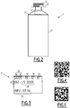
- the marking 52 comprises at least one forming information 54 relating to the identified forming station 24 in which the marked container 2 has been formed and filling information 56 relating to the identified filling station 40 in which the marked container has been formed been filled.
- the forming information 54 is for example a forming station number indicating by which forming station 24A, ..., 24E the container has been formed and the filling information 56 is for example a filling station number indicating by which filling station 40A, ..., 40E the container has been filled.
- an example of marking 52 has been shown, in which the number of the forming station 24A, ..., 24E identified is 16 and in which the filling station number 40A, ..., 40E identified is 61.
- the marking 52 also includes timestamp information 62 relating to the time at which the container 2 is marked.
- the timestamp information 62 includes, for example, the date of day 64 in the year and the date of year 66 since which the production facility started and started the production of containers.
- the calendar of day 64 is 342 and the calendar of year 66 is 05, which means that the container was marked on the 342nd day of the fifth year of production of the production facility.
- the timestamp information 62 further includes the time 68 at which the container 2 is marked. As shown in the Fig. 3 , hour 68 is marked to the nearest second. Indeed, such precision is sufficient to guarantee a unique marking of each container, even when the containers have passed through the same stations. Indeed, the rotation of a wheel of a machine or of a unit of the installation takes approximately one second between the entry point and the exit point of this wheel. Thus, two containers 2 cannot pass through the same station in a single second.
- the various information marked can be retrieved from the control console 27.
- the marking specific to the container can be a QR code or a data-Matrix, as illustrated respectively in Figures 4 and 5 .
- the invention is particularly advantageous when applied to a production installation in which the synchronization of the machines and the units is carried out so that the stations of these machines and units are said to be “paired”.
- Such pairing known per se, makes it possible to operate the stations in association so that containers passing through a particular forming station 24 of the machine 8 always pass through the same stations downstream of the forming machine 8. If, for example, a container is formed by the forming station 24A, this container will be filled by the filling station 40A. Another container formed by the forming station 24A will also be filled by the filling station 40A. The same applies to the container processing stations which will always be the same for the containers formed by the same forming station 24. In other words, the containers formed by a forming station 24 will always have the same path in the production facility.
- a second advantage is the prevention by informing of the recycling of bad containers in the production circuit.
- the fault code added to the bottle informs of attempts to put non-compliant product into circulation.
Landscapes
- Engineering & Computer Science (AREA)
- Mechanical Engineering (AREA)
- Manufacturing & Machinery (AREA)
- Physics & Mathematics (AREA)
- Thermal Sciences (AREA)
- General Engineering & Computer Science (AREA)
- Quality & Reliability (AREA)
- General Physics & Mathematics (AREA)
- Automation & Control Theory (AREA)
- Blow-Moulding Or Thermoforming Of Plastics Or The Like (AREA)
- Processing And Handling Of Plastics And Other Materials For Molding In General (AREA)
Description
L'invention concerne le domaine de la production de récipients (notamment bouteilles, flacons) par formage à partir de préformes en matière plastique, telle que par exemple le polyéthylène téréphtalate (PET), les récipients étant remplis par un produit de remplissage. Les documents
Dans une telle installation, on combine le formage des récipients à partir de préformes et une série de traitement de ces récipients dans la continuité de la réalisation de récipients, tels que le remplissage, le bouchage. Il est aussi connu d'étiqueter et/ou de marquer le récipient en ligne.In such an installation, the forming of the containers from preforms and a series of treatment of these containers are combined in the continuity of the production of containers, such as filling, capping. It is also known to label and / or mark the container online.
Au cours de l'utilisation de l'installation de production, certains dysfonctionnements sont susceptibles de se produire et par exemple aboutir à des récipients mal formés, à des récipients détruits ou à des fuites lors du remplissage. Pour détecter les récipients défectueux, il est connu de prévoir différents capteurs dans l'installation, par exemple des caméras ou autres, et il est prévu d'évacuer les récipients non conformes de l'installation afin qu'ils ne soient pas remplis par le produit de remplissage.During the use of the production facility, certain malfunctions are likely to occur and for example lead to poorly formed containers, destroyed containers or leaks during filling. To detect defective containers, it is known to provide different sensors in the installation, for example cameras or the like, and provision is made to evacuate non-conforming containers from the installation so that they are not filled by the filling product.
Cependant, de tels moyens ne permettent pas de remonter à la cause du dysfonctionnement, ni de détecter d'autres problèmes qui peuvent survenir dans l'installation, par exemple au cours du remplissage ou dans des unités particulières de l'installation. En effet, les capteurs permettent de détecter un récipient défectueux mais l'analyse de la cause de ce défaut reste difficile.However, such means do not make it possible to trace the cause of the malfunction, nor to detect other problems which may arise in the installation, for example during filling or in particular units of the installation. Indeed, the sensors make it possible to detect a defective container but the analysis of the cause of this defect remains difficult.
Pour pallier cet inconvénient, on peut par exemple prévoir que le récipient soit marqué par chaque élément de l'installation permettant son formage, son remplissage et tous les traitements qu'il est susceptible de subir afin de permettre de tracer le cheminement du récipient dans l'installation. Cependant, la multiplicité des marquages complexifie l'installation et est susceptible de fragiliser le récipient en augmentant les zones marquées du récipient. En outre, même en ajoutant plusieurs marquages, il n'est pas possible d'identifier de façon unique chaque récipient, car plusieurs récipients passant par les mêmes éléments de l'installation auront un marquage identique.To overcome this drawback, one can for example provide that the container is marked by each element of the installation allowing its forming, filling and all the treatments that it is likely to undergo in order to allow to trace the path of the container in the 'installation. However, the multiplicity of markings complicates the installation and is likely to weaken the container by increasing the marked areas of the container. Furthermore, even by adding several markings, it is not possible to uniquely identify each container, since several containers passing through the same elements of the installation will have an identical marking.
L'invention concerne en particulier les installations de production de récipients qui assurent une succession de traitements sur chaque récipient et qui tiennent individuellement chaque récipient tout au long du parcours de traitement du récipient dans l'installation de production. De telles installation présentent un système de contrôle susceptible d'enregistrer en temps réel les valeurs mesurées ou détectées par un grand nombre de capteurs de la machine, d'enregistrer le début d'un grand nombre d'opérations effectué sur le récipient et de pouvoir mettre en regards de chaque récipient un nombre important de données machine concernant chaque récipient individuel.The invention relates in particular to container production installations which ensure a succession of treatments on each container and which hold each container individually throughout the treatment path of the container in the production installation. Such installations present a control system capable of recording in real time the values measured or detected by a large number of machine sensors, of recording the start of a large number of operations. performed on the container and to be able to compare each container with a large number of machine data relating to each individual container.
Cependant, l'analyse d'un défaut sur un récipient peut nécessiter de faire un test sur ce récipient après que celui-ci ait quitté l'installation. Par exemple, lorsque l'installation comprend le dépôt d'une couche sur une surface du récipient, il peut être utile de procéder à un test manuel long, ne pouvant pas être effectué en ligne à la cadence de production. Parfois le test pertinent pour détecter une origine d'un défaut peut être un test détruisant le récipient. La difficulté vient de ce que, une fois que le récipient a quitté l'installation, le lien avec le système de control de l'installation est rompu. Il est difficile de faire le lien entre le résultat d'un test « hors-ligne » et l'historique de ce que l'installation de production a fait sur ce récipient particulier.However, the analysis of a fault on a container may require a test on this container after it has left the installation. For example, when the installation includes the deposition of a layer on a surface of the container, it may be useful to carry out a long manual test, which cannot be carried out online at the production rate. Sometimes the relevant test to detect the origin of a defect can be a test destroying the container. The difficulty comes from the fact that, once the container has left the installation, the link with the installation control system is broken. It is difficult to make the connection between the result of an “offline” test and the history of what the production facility has done on this particular container.
L'un des buts de l'invention est de proposer un procédé de production d'une succession de récipient, permettant d'élargir l'analyse des défauts et/ou des dérives susceptibles de se produire dans une installation de production de récipient.One of the aims of the invention is to propose a method for producing a succession of containers, making it possible to broaden the analysis of faults and / or drifts likely to occur in a container production installation.
A cet effet, l'invention concerne un procédé de production d'une succession de récipients à partir d'une succession de préformes en matières plastiques chauffées dans une installation de production de récipients comprenant au moins une station de chauffage de la succession de préformes, une machine de formage comprenant une pluralité de stations de formage, une ou plusieurs machines de traitement comprenant chacune une pluralité de stations de traitement, le procédé comprenant les étapes suivantes :
- circulation de la succession de préformes dans la station de chauffage jusqu'à la machine de formage au cours de laquelle chaque préforme est tenue individuellement et chauffée à une température de référence,
- formage de la succession de préformes dans la machine de formage, chaque préforme chauffée étant placée dans une station de formage dans laquelle ladite préforme est formée en un récipient, de sorte que ladite succession de préformes est formée en une succession de récipients individuels,
- traitement de la succession de récipients individuels dans la machine de traitement, chaque récipient individuel étant placé dans une station de traitement,
- circulation de chaque récipient tenu individuellement entre la machine de formage et la ou les machines de traitement,
- circulation of the succession of preforms in the heating station up to the forming machine during which each preform is held individually and heated to a reference temperature,
- forming the succession of preforms in the forming machine, each heated preform being placed in a forming station in which said preform is formed into a container, so that said succession of preforms is formed into a succession of individual containers,
- processing of the succession of individual containers in the processing machine, each individual container being placed in a processing station,
- circulation of each container held individually between the forming machine and the processing machine (s),
Grâce à l'identification individuelle propre à chaque récipient produit, il est possible de faire le lien entre des mesures faite à postériori après la production du récipient et l'ensemble des données machine relative à la production de ce récipient particulier. Cela permet d'élargir les capacités d'analyse des défauts et/ou de maintenance prédictive de l'installation.Thanks to the individual identification specific to each container produced, it is possible to make the link between measurements made afterwards after the production of the container and all the machine data relating to the production of this particular container. This makes it possible to expand the capacity for fault analysis and / or predictive maintenance of the installation.
Les stations de formage et de traitement tiennent la préforme ou le récipient qui y est placé. Ainsi, l'installation de production de récipient assure la tenue individuelle de la préforme ou du récipient tout au long du parcours de production de ce récipient.The forming and processing stations hold the preform or the container placed therein. Thus, the container production installation ensures the individual holding of the preform or of the container throughout the production path of this container.
La période prédéterminée de suivi peut être contractuelle et couvrir l'ensemble de la vie de l'installation de production. Ella peut alternativement être choisie par l'opérateur et viser une phase d'investigation particulière de l'installation.The predetermined follow-up period may be contractual and cover the entire life of the production facility. It can alternatively be chosen by the operator and target a particular phase of investigation of the installation.
Selon une autre caractéristique du procédé selon l'invention, le marquage propre au récipient à identifier comprend une information de poste relative à au moins l'un des éléments ayant tenu, ou devant tenir ledit récipient à identifier lors de la production du récipient à identifier, et une information d'horodatage relative au moment où ledit récipient à identifier est marqué.According to another characteristic of the method according to the invention, the marking specific to the container to be identified includes item information relating to at least one of the elements which have held, or which must hold, the said container to be identified during the production of the container to be identified. , and timestamp information relating to the time when said container to be identified is marked.
Grâce au fait que préformes et récipients sont tenus individuellement durant tout leur passages dans l'installation de production, il est possible de connaître à chaque instant la position de chaque préforme ou récipient dans l'installation et ainsi d'identifier les différentes stations par lesquelles une préforme puis le récipient formé à partir de cette préforme passent. Ainsi, en une seule étape de marquage, il est possible d'ajouter au marquage des informations sur les stations par lesquelles le récipient est passé. Ainsi, on ne fragilise pas le récipient en multipliant les étapes et les zones de marquage. En outre, grâce aux informations d'horodatage sur l'instant du marquage, il est possible d'identifier de façon unique chaque récipient. En effet, les marquages de deux récipients passés par les mêmes stations de l'installation de production se distingueront l'un de l'autre par l'information sur le moment auquel le marquage a eu lieu.Thanks to the fact that preforms and containers are held individually throughout their passage through the production installation, it is possible to know at all times the position of each preform or container in the installation and thus to identify the different stations by which a preform then the container formed from this preform pass. Thus, in a single marking step, it is possible to add to the marking information on the stations through which the container has passed. Thus, the container is not weakened by multiplying the stages and the marking zones. In addition, thanks to the time stamp information at the time of marking, it is possible to uniquely identify each container. Indeed, the markings of two containers passed through the same stations of the production facility will be distinguished from one another by the information on the moment at which the markings took place.
Avantageusement, l'information d'horodatage comprend la date et l'heure à la seconde près auxquelles le marquage du récipient a lieu.Advantageously, the time stamping information includes the date and time to the nearest second at which the marking of the container takes place.
Les inventeurs ont constaté qu'une information d'horodatage à la seconde près est suffisante pour identifier chaque récipient de façon unique. En effet, les cycles de production de l'installation sont tels que deux récipients ne peuvent pas passer par les mêmes stations dans une même seconde. Ainsi, l'horodatage à la seconde près permet de distinguer deux récipients l'un de l'autre, même si ceux-ci sont passées par les mêmes stations.The inventors have found that time stamping information to the nearest second is sufficient to uniquely identify each container. In fact, the production cycles of the installation are such that two containers cannot pass through the same stations in the same second. Time-stamping to the nearest second allows to distinguish two receptacles from one another, even if these have passed through the same stations.
Selon une variante, le marquage propre au récipient à identifier comprend un numéro de chronologie de la production du récipient au cours de la période de suivi. Par numéro de chronologie, on entend n'importe quelle série de codes alphanumérique ou similaire susceptibles d'être classé selon un ordre, de sorte que l'ordre des marquages correspond à l'ordre de production des récipients.According to one variant, the marking specific to the container to be identified comprises a chronology number of the production of the container during the monitoring period. By chronology number is meant any series of alphanumeric codes or the like which can be classified according to an order, so that the order of the markings corresponds to the order of production of the containers.
Selon un mode de réalisation, le marquage propre au récipient à identifier comprend en outre un codage propre à l'installation ayant produit ledit récipient et/ou un codage de la période de suivi. Un tel mode de réalisation peut permettre d'identifier un récipient produit selon ce procédé en le distinguant de tous les autres, éventuellement produit par une autre machine. Ainsi le marquage peut servir de base pour détecter des responsabilités.According to one embodiment, the marking specific to the container to be identified further comprises a coding specific to the installation having produced said container and / or a coding of the monitoring period. Such an embodiment can make it possible to identify a container produced according to this process by distinguishing it from all the others, possibly produced by another machine. Thus the marking can serve as a basis for detecting responsibilities.
Selon une autre caractéristique du procédé selon l'invention, l'une desdites machines de traitement est une machine d'application de ladite couche barrière sur la paroi interne du récipient comprenant une pluralité de stations d'application, le procédé comprenant une étape d'application d'une couche barrière à la succession de récipients, chaque récipient étant placé dans une station d'application identifiée dans laquelle une couche barrière est appliquée sur la paroi interne dudit récipient, l'étape de marquage du récipient à identifier comprenant le marquage d'une information relative à la station d'application identifiée dans laquelle une couche barrière a été ou sera appliquée audit récipient.According to another characteristic of the method according to the invention, one of said treatment machines is a machine for applying said barrier layer to the internal wall of the container comprising a plurality of application stations, the method comprising a step of applying a barrier layer to the succession of containers, each container being placed in an identified application station in which a barrier layer is applied to the inner wall of said container, the step of marking the container to be identified comprising marking information relating to the identified application station in which a barrier layer has been or will be applied to said container.
L'identification de la station ayant réalisée l'application de la couche barrière est particulièrement utile pour le contrôle hors-ligne de perméabilité. En effet, la couche barrière permet d'améliorer l'imperméabilité au gaz du récipient, par exemple pour empêcher le dioxyde de carbone (CO2) d'échapper du récipient par la paroi de celui-ci lorsque le récipient contient un produit carbonaté ou pour empêcher l'oxydation par l'air ambiant d'un produit contenu dans le récipient. Afin d'évaluer la qualité de la couche barrière, il est nécessaire d'effectuer des tests de perméabilité en dehors de l'installation et il est donc utile d'identifier de façon précise la station d'application qui a réalisé la couche barrière sur le récipient testé.The identification of the station having applied the barrier layer is particularly useful for off-line permeability control. Indeed, the barrier layer makes it possible to improve the gas impermeability of the container, for example to prevent carbon dioxide (CO 2 ) from escaping from the container through the wall thereof when the container contains a carbonated product or to prevent oxidation by ambient air of a product contained in the container. In order to assess the quality of the barrier layer, it is necessary to carry out permeability tests outside the installation and it is therefore useful to identify precisely the application station which produced the barrier layer on the container tested.
Selon d'autres caractéristiques du procédé selon l'invention :
- le procédé comprend une autre étape de traitement qui est une étape de remplissage de chaque récipient produit, l'une des machines de traitement correspondante étant une machine de remplissage, l'étape de marquage du récipient à identifier se produisant entre l'étape d'application d'une couche barrière et l'étape de remplissage.
- l'installation comprend une unité de bouchage comprenant une pluralité de stations de bouchage; procédé dans lequel, au cours de l'étape de bouchage de la succession de récipients, chaque récipient est placé dans une station de bouchage identifiée dans laquelle un bouchon est fixé sur ledit récipient, l'étape de marquage du récipient à identifier comprenant le marquage d'une information relative à la station de bouchage identifiée dans laquelle un bouchon a été fixé sur ledit récipient.
- l'étape de marquage comprend le marquage d'une information de produit relative au produit de remplissage introduit dans le récipient au cours de l'étape de remplissage.
- l'installation de production comprend une unité d'étiquetage ayant une pluralité de stations d'étiquetage ; procédé dans lequel, au cours de l'étape d'étiquetage, chaque récipient est placé dans une station d'étiquetage identifiée dans laquelle une étiquette est fixée sur ledit récipient, l'étape de marquage du récipient à identifier comprenant le marquage d'une information relative à la station d'étiquetage identifiée dans laquelle une étiquette a été fixée sur ledit récipient.
- the method comprises another processing step which is a step of filling each container produced, one of the corresponding processing machines being a filling machine, the step of marking the container to identify occurring between the step of applying a barrier layer and the filling step.
- the installation comprises a capping unit comprising a plurality of capping stations; process in which, during the stoppering step of the succession of containers, each container is placed in an identified corking station in which a stopper is fixed on said container, the step of marking the container to be identified comprising marking information relating to the identified corking station in which a cap has been fixed on said container.
- the marking step comprises marking product information relating to the filling product introduced into the container during the filling step.
- the production installation comprises a labeling unit having a plurality of labeling stations; process in which, during the labeling step, each container is placed in an identified labeling station in which a label is attached to said container, the step of marking the container to be identified comprising marking a information relating to the identified labeling station in which a label has been affixed to said container.
Comme indiqué précédemment, le transport positif des préformes et des récipients permet d'identifier facilement chacune des stations par lesquels une préforme puis le récipient, obtenu à partir de cette préforme, passent. Ainsi, il est possible d'ajouter lors du marquage les informations relatives à ces stations afin d'améliorer la traçabilité du récipient.As indicated above, the positive transport of the preforms and of the containers makes it possible to easily identify each of the stations through which a preform and then the container, obtained from this preform, pass. Thus, it is possible to add, during the marking, the information relating to these stations in order to improve the traceability of the container.
L'étape de marquage peut également servir à marquer des informations usuelles sur le produit de remplissage contenu dans le récipient, telles que, par exemple, une date de péremption ou autre. Ainsi, une unique étape de marquage permet d'imprimer des informations relatives à la traçabilité du récipient et relatives au produit contenu dans le récipient.The marking step can also be used to mark usual information on the filling product contained in the container, such as, for example, an expiration date or the like. Thus, a single marking step makes it possible to print information relating to the traceability of the container and relating to the product contained in the container.
Selon une autre caractéristique du procédé selon l'invention, le marquage de chaque récipient est effectué dans une zone unique dudit récipient, les informations relatives aux stations identifiées et d'horodatage étant placées les unes adjacentes aux autres dans ladite zone unique.According to another characteristic of the method according to the invention, the marking of each container is carried out in a single zone of said container, the information relating to the stations identified and of time stamping being placed one next to the other in said single zone.
En prévoyant une zone de marquage unique, on limite les risques d'endommagement des récipients et on simplifie la lecture des informations marquées sur le récipient.By providing a single marking area, the risk of damage to the containers is limited and the information marked on the container is simplified to read.
Selon un autre aspect, l'invention concerne un procédé de commande d'une installation de production d'une succession de récipients à partir d'une succession de préformes en matières plastiques comprenant :
- une première étape d'acquisition de données machine mettant en oeuvre le procédé précité, dans laquelle pour chaque récipient individuel produit, la console de commande mémorise d'une part le marquage propre audit récipient et d'autre part une série de données spécifiques relatives aux stations de formage, et/ou de traitement, et/ou aux éléments ayant tenus ledit récipient au cours de sa production, et/ou une série de données générales relatives au fonctionnement de l'installation lors de la production dudit récipient,
- une deuxième étape d'acquisition de données récipient, au cours de laquelle, on mesure une ou plusieurs grandeurs physiques de chacun des récipients identifié individuellement au cours de la première étape,
- une troisième étape de constitution d'une base de données mixte mettant en correspondance pour chaque récipient identifié individuellement lors de la première étape, d'une part la ou les mesures de la deuxième étape, et la ou les séries de données acquises lors de la première étape.
- a first step of acquiring machine data implementing the aforementioned method, in which for each individual container produced, the control console stores on the one hand the marking specific to said container and on the other hand a series of specific data relating to the forming, and / or processing stations and / or the elements which held said container during its production, and / or a series of general data relating to the operation of the installation during the production of said container,
- a second step of acquiring container data, during which one or more physical quantities of each of the containers identified individually during the first step are measured,
- a third stage of constitution of a mixed database matching for each container identified individually during the first stage, on the one hand the measure or measures of the second stage, and the series or series of data acquired during the first stage.
Selon une mode de réalisation, le procédé de commande comprend une étape de diagnostic, au cours de laquelle on compare les données récipient par rapport à des valeurs cibles préenregistrées correspondants aux grandeurs mesurées, et on détermine un dysfonctionnement avéré ou imminent sur l'une ou plusieurs des stations de formage et/ou de traitement et/ou d'éléments de tenu de l'installation. La détection d'un défaut imminent peut être détecté en mesurant une dérive d'une données récipient et/ou une donnée machine et en détectant que cette dérive dépasse un seuil préenregistré.According to one embodiment, the control method comprises a diagnostic step, during which the container data are compared with respect to prerecorded target values corresponding to the quantities measured, and a proven or imminent malfunction is determined on one or more several of the forming and / or processing stations and / or elements of the installation. The detection of an imminent fault can be detected by measuring a drift of a container data and / or a machine data and by detecting that this drift exceeds a pre-recorded threshold.
Selon un autre mode de réalisation, le procédé de commande comprend une étape d'analyse de la base de données mixte, au cours de laquelle on établit au moins une loi de corrélation entre des données récipient et des données machine, et une étape de correction dans laquelle on calcule d'après la ou les lois de corrélation un ou plusieurs paramètres machine ajustés susceptibles lors d'un prochain cycle de production de produire des récipients dont une ou plusieurs grandeurs physiques seront plus proches de la ou les cibles préenregistrées, que lors de la première étape.According to another embodiment, the control method comprises a step of analyzing the mixed database, during which at least one correlation law is established between container data and machine data, and a correction step. in which one or more adjusted machine parameters are calculated according to the correlation law (s) likely during a next production cycle to produce containers of which one or more physical quantities will be closer to the prerecorded target (s), than during from the first step.
Selon un autre aspect, l'invention concerne une installation de production, d'une succession de récipients à partir d'une succession de préformes en matières plastiques chauffées permettant la mise en oeuvre d'un procédé de production précité, ladite installation comprenant :
- une station de chauffage de la succession de préformes permettant de tenir et de chauffer chacune desdites préformes à une température de référence,
- une machine de formage de la succession de préformes en une succession de récipients, ladite machine de formage comprenant une pluralité de stations de formage identifiées, chaque station de formage recevant une préforme et formant ladite préforme en un récipient,
- au moins une machine de traitement de la succession de récipients, ladite machine de traitement comprenant une pluralité de stations de traitement du récipient produit,
- un dispositif de transport positif tenant individuellement chaque récipient entre la machine de formage et la ou les machines de traitement,
- une unité de marquage appliquant un marquage sur chacun des récipients de la succession de récipients, et une console de contrôle reliée à l'unité de marquage et générant le marquage à appliquer,
- a station for heating the succession of preforms making it possible to hold and heat each of said preforms to a reference temperature,
- a machine for forming the succession of preforms into a succession of containers, said forming machine comprising a plurality of identified forming stations, each forming station receiving a preform and forming said preform into a container,
- at least one machine for processing the succession of containers, said processing machine comprising a plurality of stations for processing the container produced,
- a positive transport device holding each container individually between the forming machine and the processing machine (s),
- a marking unit applying a marking to each of the containers of the succession of containers, and a control console connected to the marking unit and generating the marking to be applied,
Selon un mode de réalisation, chaque préforme circulant dans la station de chauffage est tenue par un élément de préhension, chaque récipient individuel en cours de formage est tenu par la station de formage qui le forme, chaque récipients individuel en cours de traitement est tenu par la station de traitement qui le traite, chaque récipients individuel circulant entre la machine de formage et la ou les machines de traitement est tenu par un élément de préhension du dispositif de transport positif, lesdits éléments de préhension, la station de formage ou la station de traitement de la ou de chaque machine de traitement constituent des éléments ayant tenu, ou devant tenir le récipient à identifier, dont une information est enregistrée dans la console de commande associé au marquage propre au récipient à identifier.According to one embodiment, each preform circulating in the heating station is held by a gripping element, each individual container being formed is held by the forming station which forms it, each individual container being treated is held by the processing station which processes it, each individual container circulating between the forming machine and the processing machine or machines is held by a gripping element of the positive transport device, said gripping elements, the forming station or the processing station processing of the or each processing machine constitute elements which have held, or which must hold, the container to be identified, of which information is recorded in the control console associated with the marking specific to the container to be identified.
L'invention est particulièrement avantageuse dans le cas où les stations des différentes machines sont « appairées », c'est-à-dire que deux stations de deux machines différentes fonctionnent en coopération pour traiter une préforme et le récipient issu de la préforme. En d'autres termes, les récipients formés à partir de préformes étant passées par une station de formage particulière de la machine de formage seront toujours remplis par la même station de remplissage de la machine de remplissage. Ainsi, on connaît le trajet suivi par une préforme et un récipient issu de la préforme dès que l'on connaît la station de formage par laquelle la préforme passe. Dès lors, le marquage est simplifié puisque les informations marquées sur deux récipients passés par les mêmes stations sont identiques en dehors des informations d'horodatage.The invention is particularly advantageous in the case where the stations of the different machines are "paired", that is to say that two stations of two different machines operate in cooperation to process a preform and the container from the preform. In other words, the containers formed from preforms having passed through a particular forming station of the forming machine will always be filled by the same filling station of the filling machine. Thus, we know the path followed by a preform and a container from the preform as soon as we know the forming station through which the preform passes. Consequently, the marking is simplified since the information marked on two containers passed through the same stations is identical apart from the time stamping information.
Selon un mode de réalisation, l'une des machines de traitement est une machine de remplissage du récipient produit par l'installation, la machine de remplissage comprenant une pluralité de station de remplissage, et dans laquelle chaque station de remplissage de la machine de remplissage est associée à une station de formage identifiée de la machine de formage de sorte que pour chaque station de remplissage, la console de contrôle sais de quelle station de formage provient systématiquement le récipient que la station de remplissage est en train de remplir.According to one embodiment, one of the processing machines is a machine for filling the container produced by the installation, the filling machine comprising a plurality of filling stations, and in which each filling station of the filling machine is associated with an identified forming station of the forming machine so that for each filling station, the control console knows which forming station systematically comes from the container that the filling station is filling.
D'autres aspects et avantages de l'invention apparaîtront à la lecture de la description qui suit, donnée à titre d'exemple et faite en référence aux dessins annexés, dans lesquels :
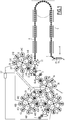
- la
Fig. 1 est une représentation schématique de dessus d'une installation de production selon l'invention, - la
Fig. 2 est une représentation schématique d'un récipient obtenu après l'étape de marquage du procédé de production selon l'invention, - la
Fig. 3 est une représentation des informations marquées sur un récipient après l'étape de marquage du procédé de production selon l'invention, et - Les
figures 4 et 5 illustrent deux exemples de marquage, un QR code (Figure 4 ), et un data-matrix (figure 5 ).
- the
Fig. 1 is a schematic representation from above of a production installation according to the invention, - the
Fig. 2 is a schematic representation of a container obtained after the marking step of the production process according to the invention, - the
Fig. 3 is a representation of the information marked on a container after the marking step of the production process according to the invention, and - The
Figures 4 and 5 illustrate two examples of marking, a QR code (Figure 4 ), and a data-matrix (figure 5 ).
En référence à la
L'installation de production 1 comprend au moins une station de chauffage 6, une machine de formage 8, une machine de remplissage 10, un dispositif de transport 12 et une unité de marquage 14. The production installation 1 comprises at least one
Chaque préforme 4 comprend un corps 16, un col 18 et une bague 20. Le corps 6 présente par exemple la forme d'un tube à essai avec un fond fermé et définit un volume interne s'étendant selon un axe principal A. Le col 8 s'étend dans la continuité du corps 6 à l'opposé du fond et forme une ouverture supérieure par laquelle un fluide peut être introduit dans le volume interne de la préforme, comme cela sera décrit ultérieurement. Le col 8 de la préforme présente par exemple la forme définitive qu'il aura dans le récipient 2 formé à partir de la préforme 4 et comprend, par exemple, un filetage sur sa paroi externe pour permettre la fixation d'un bouchon sur le récipient. La bague 10 s'étend entre le corps 6 et le col 8 radialement vers l'extérieur et forme par exemple une bague de transport par laquelle la préforme peut être saisie et transportée, comme cela sera décrit ultérieurement. La forme de préforme donnée ci-dessus ne l'est qu'à titre d'exemple et d'autres formes pourraient être envisagées, tant que celles-ci sont appropriées pour former un récipient par introduction d'un fluide dans la préforme. Ainsi, à titre d'exemple, la préforme pourrait présenter un col lisse, être dépourvue de bague, et/ou avoir d'autres variantes de formes selon divers modèles de préforme susceptibles d'être utilisés dans l'installation de production 1. La matière plastique de la préforme est par exemple du polyéthylène téréphtalate (PET). En variante, la matière plastique pourrait être différente du PET, tant que cette matière est susceptible d'être rendue malléable et déformable pour permettre la réalisation d'un récipient par introduction d'un fluide dans la préforme.Each
La station de chauffage 6 est agencée pour chauffer chaque préforme 4 à une température de référence à laquelle la préforme 4 est dans un état malléable et peut être formée en un récipient. La température de référence est comprise entre la température de transition vitreuse et la température de cristallisation du matériau de la préforme 4. La station de chauffage 6 comprend par exemple une pluralité d'éléments de chauffage répartis dans la station de chauffage 6 selon un trajet et agencés pour chauffer la succession de préformes 4 se déplaçant devant les éléments de chauffage grâce au dispositif de transport 12. Les éléments de chauffage sont par exemple en outre répartis selon une direction parallèle à l'axe des préformes de sorte à permettre de chauffer l'ensemble du corps 6 des préformes 4. Une telle station de chauffage 6, ou four à défilement, étant connue en soi, elle ne sera pas décrite plus en détail ici.The
En sortie de la station de chauffage 6, les préformes chauffées sont déplacées jusqu'à la machine de formage 8 par le dispositif de transport 12.On leaving the
Le dispositif de transport 12 est par exemple formé par un convoyeur dans la station de chauffage 6. En sortie de la station de chauffage 6, le dispositif de transport 12 est par exemple formé par une pluralité de roues de transfert 22, mobiles en rotation, pourvues chacune en périphérie d'une pluralité d'éléments de préhension. Chaque élément de préhension, par exemple du type pince ou autre, est agencé pour saisir une préforme 4 de la succession de préforme et la transporter jusqu'à la roue suivante où un élément de préhension de la roue suivante prélève la préforme et ainsi de suite jusqu'à la machine de formage 8. Le nombre de roues peut varier d'une installation de production à une autre et dépend de l'agencement de l'installation de production. Une seule roue pourrait être prévue entre la sortie de la station de chauffage 6 et la machine de formage 8, comme représenté sur la
Le dispositif de transport 12 est un dispositif de transport positif, c'est-à-dire que le dispositif de transport 12 est agencé pour que la position d'une préforme 4 soit toujours connue dans l'installation de production 1. Cela peut être obtenu par exemple en entraînant une ou plusieurs roues en rotation au moyen d'un moteur synchrone et en asservissant la rotation des autres roues à la roue entraînée en rotation par le moteur synchrone, par exemple au moyen de courroies. Une autre solution consiste à entraîner en rotation chaque roue au moyen d'un moteur synchrone. En effet, la position angulaire d'un moteur synchrone est connue à tout instant, et il est donc possible d'en déduire la position d'une préforme 4 dans l'installation de production grâce à la connaissance de la position angulaire des roues à chaque instant.The transport device 12 is a positive transport device, that is to say that the transport device 12 is arranged so that the position of a
La machine de formage 8 comprend une pluralité de stations de formage 24 agencées chacune pour recevoir et former une préforme 4 de la succession de préformes 4 en un récipient. A cet effet, chaque station de formage 24 comprend un moule 26 et un dispositif d'injection d'un fluide de formage. Le moule 26 comprend une cavité de moulage présentant la forme du récipient à produire et agencée pour recevoir le corps 6 de la préforme. Le dispositif d'injection est agencé pour injecter un fluide de formage sous pression dans le volume interne de la préforme 4 par l'ouverture supérieure de celle-ci afin que le corps 6 de la préforme acquière la forme de la cavité de moulage. Le fluide de formage est par exemple un gaz, par exemple de l'air sous pression. Chaque station de formage 24 peut en outre comprendre une tige d'étirage agencée pour exercer un appui sur le fond de la préforme 6 afin de l'étendre selon son axe.The forming machine 8 comprises a plurality of forming stations 24 each arranged to receive and form a
Chaque station de formage 24 est identifiée, c'est-à-dire qu'elle est référencée dans une console de contrôle 27 de l'installation. Ainsi, à titre d'exemple, la machine de formage 8 comprend dix-huit stations de formage. Pour des raisons de simplicité et pour faciliter la lecture de la figure, seules cinq stations de formage 24A, 24B, 24C, 24D et 24E ont été représentées. Les stations de formage 24 sont portées par une roue de formage 28, ou carrousel, mobile en rotation autour d'un axe de rotation parallèle aux axes de rotation des roues de transfert 22. Les stations de formage 24 sont portées sur la périphérie de la roue de formage 28 de sorte qu'elles se déplacent le long d'un trajet circulaire défini par la roue de formage 28 entre un point d'entrée 30 et un point de sortie 32. Au point d'entrée, le moule est ouvert et est agencé pour recevoir une préforme 4 de la roue de transfert 22, puis le moule 26 est fermé, le dispositif d'injection est placé en communication fluidique avec le volume interne de la préforme et le fluide de formage est injecté dans la préforme au cours du déplacement de la station de formage entre le point d'entrée 30 et le point de sortie 32. Au point de sortie 32, le moule 26 est ouvert et le récipient formé est extrait de la station de formage 24. La structure et le fonctionnement de telles stations de formage 24 et, plus généralement, de la machine de formage 8 sont connus en tant que tels et ne seront pas décrit plus en détail ici.Each forming station 24 is identified, that is to say it is referenced in a
Il convient de noter que, dans la machine de formage 8, le dispositif de transport 12 est formé par la roue de formage 28 et les moules eux-mêmes qui transportent les préformes et les récipients du point d'entrée 30 au point de sortie 32. La roue de formage 28 est ainsi entraînée de façon à connaître la position des stations de formage 24 à tout instant, par exemple en entraînant la roue de formage 28 au moyen d'un moteur synchrone. Par conséquent, l'installation permet de savoir dans quelle station de formage 24 une préforme 4 est placée et formée en un récipient. La console de contrôle 27 enregistre ainsi dans quelle station de formage 24A, 24B,..., 24E une préforme particulière passe.It should be noted that, in the forming machine 8, the transport device 12 is formed by the forming
Au point de sortie 32 de la machine de formage 8, le dispositif de transport 12 comprend une roue de transfert agencée pour prélever les récipients 2 en sortie de la machine de formage 8 et pour les transférer vers la machine de remplissage 10.At the exit point 32 of the forming machine 8, the transport device 12 comprises a transfer wheel arranged to take the
Les récipients obtenus, dont un exemple est représenté sur la
Selon des variantes de réalisation de l'installation de production, une ou plusieurs unités de traitement 34 de la succession de récipients 2 peuvent être prévus entre la machine de formage 8 et la machine de remplissage 10. Chaque unité de traitement 34 comprend une pluralité de stations de traitement 36 identifiées agencées pour appliquer un traitement particulier aux récipients 2 de la succession de récipients et par exemple portées par une roue de traitement 38. Comme pour la machine de formage 8, dans l'unité de traitement 34, le dispositif de transport 12 est formé par la roue de traitement 38 et les stations de traitement 36 elles-mêmes et la roue de traitement 38 est agencée de façon à ce que l'on sache par quelle station de traitement identifiée 36 un récipient 2 de la succession de récipients est traité. La console de contrôle 27 enregistre ainsi dans quelle station de traitement un récipient particulier passe.According to alternative embodiments of the production installation, one or
Le dispositif de transport 12 est en outre agencé pour transférer les récipients 2 entre les points de sortie d'une unité de traitement 34 au point d'entrée d'une autre unité de traitement 34 et jusqu'à la machine de remplissage 10. Il convient de noter que les roues de transfert 22 du dispositif de transfert peuvent également permettre de façon connue de modifier le pas entre deux préformes 4 ou récipients 2 successifs pour adapter ce pas au nombre de stations de traitement 36 prévues dans les unités de traitement 34. En effet, la machine de formage 8, la machine de remplissage 10 et les différentes unités de traitement 34 ne comprennent pas nécessairement le même nombre de stations, ce nombre de station dépendant de l'encombrement de celles-ci sur une roue et de la cadence de traitement des stations. En effet, les stations doivent permettre de réaliser le traitement en un tour de roue de traitement. Les éléments de préhension du dispositif de transport 12 sont par exemple adaptés pour transporter les récipients 2 par leur bague 20.The transport device 12 is further arranged to transfer the
A titre d'exemple, l'unité de traitement 34 peut être une unité d'étiquetage permettant d'étiqueter chaque récipient 2, c'est-à-dire d'appliquer une étiquette sur chaque récipient. A cet effet, l'unité d'étiquetage comprend une pluralité de stations d'étiquetage identifiées agencées chacune pour recevoir un récipient et appliquer une étiquette sur ledit récipient. Les stations d'étiquetage sont par exemple portées par une roue d'étiquetage mobile en rotation et déplaçant de façon positive les récipients entre un point d'entrée et un point de sortie, les étiquettes étant appliquées sur les récipients au cours de ce déplacement.By way of example, the
En variante ou en complément, l'unité de traitement 34 ou une autre unité de traitement peut être une unité d'application d'une couche barrière sur la paroi interne des récipients 2. L'unité d'application comprend une pluralité de stations d'application agencées chacune pour appliquer une couche barrière sur la paroi interne d'un récipient 2 reçu dans ladite station d'application. Une telle station d'application est par exemple décrite dans le document
En variante ou en complément, l'unité de traitement 34 ou une autre unité de traitement peut être une unité de nettoyage des récipients agencée pour injecter un produit de nettoyage dans les récipients.As a variant or in addition, the
Pour des raisons de simplicité et pour faciliter la lecture de la figure, seule une unité de traitement 34, comprenant cinq stations de traitement 36, a été représentée sur la
La machine de remplissage 10 comprend une pluralité de stations de remplissage 40 agencées chacune pour recevoir et remplir un récipient 2 de la succession de récipients 2. A cet effet, chaque station de remplissage 40 comprend un support de récipient 42 et un dispositif de remplissage du récipient. Le dispositif de remplissage est agencé pour introduire un produit de remplissage dans le volume interne du récipient 2 par l'ouverture supérieure de celui-ci. Le produit de remplissage est par exemple un liquide, qui peut être plus ou moins visqueux, carbonaté ou non, comprendre des morceaux solides. Le produit de remplissage peut être refroidi, à température ambiante ou chaud.The filling
Chaque station de remplissage 40 est identifiée, c'est-à-dire qu'elle est référencée dans la console de contrôle 27 de l'installation. Ainsi, à titre d'exemple, la machine de remplissage 10 comprend cent-vingt stations de remplissage 40. Pour des raisons de simplicité et pour faciliter la lecture de la figure, seules cinq stations de remplissage 40A, 40B, 40C, 40D et 40E. Les stations de remplissage 40 sont portées par une roue de remplissage 44, ou carrousel, mobile en rotation autour d'un axe de rotation parallèle aux axes de rotation des roues de transfert 22. Les stations de remplissage 40 sont portées sur la périphérie de la roue de remplissage 44 de sorte qu'elles se déplacent le long d'un trajet circulaire défini par la roue de remplissage 44 entre un point d'entrée et un point de sortie. En le point d'entrée et le point de sortie, le dispositif de remplissage est placé en regard du volume interne du récipient 2 et le produit de remplissage est introduit dans le récipient au cours du déplacement de la station de remplissage. Au point de sortie, le récipient rempli est extrait de la station de remplissage 40. La structure et le fonctionnement de telles stations de remplissage 40 et, plus généralement, de la machine de remplissage 10 sont connus en tant que tels et ne seront pas décrit plus en détail ici.Each filling station 40 is identified, that is to say that it is referenced in the
Il convient de noter que, dans la machine de remplissage 10, le dispositif de transport 12 est formé par la roue de remplissage 44 et les supports de récipient 42 eux-mêmes qui transportent les récipients du point d'entrée au point de sortie. La roue de remplissage 44 est ainsi entraînée de façon à connaître la position des stations de remplissage 40 à tout instant, par exemple en entraînant la roue de remplissage 44 au moyen d'un moteur synchrone. Par conséquent, l'installation permet de savoir dans quelle station de remplissage un récipient 2 est placé et rempli. La console de contrôle 27 enregistre ainsi dans quelle station de remplissage 40A, 40B,..., 40E un récipient particulier passe.It should be noted that, in the filling
En sortie de la machine de remplissage 10, le dispositif de transport 12 comprend une ou plusieurs roues de transfert 22 transportant les récipients remplis à une unité de bouchage 46, comprenant une pluralité de stations de bouchage 48 entraînées en rotation par une roue de bouchage 50, chacune agencée pour appliquer un bouchon sur le col 18 d'un récipient 2 de la succession de récipients. Comme pour les autres unités et machines de l'installation, dans l'unité de bouchage, le dispositif de transport 12 est formé par la roue de bouchage 50 et les stations de bouchage 48 elles-mêmes et la roue de bouchage 50 est entraînée de façon à connaître la position des stations de bouchage 48 à tout instant, par exemple en entraînant la roue de bouchage 50 au moyen d'un moteur synchrone. Par conséquent, l'installation permet de savoir dans quelle station de bouchage un récipient 2 est placé. La console de contrôle 27 enregistre ainsi dans quelle station de bouchage 50 un récipient particulier passe.At the outlet of the filling
En sortie de l'unité de bouchage 50, les récipients 2 sont retirés de l'installation de production 1.At the outlet of the capping unit 50, the
Le dispositif de marquage 14 est agencé pour appliquer un marquage 52 (
Le marquage 52 comprend une pluralité d'informations relatives au cheminement du récipient 2 et de la préforme dont il est issu dans l'installation de production 1. En effet, comme indiqué précédemment, le dispositif de transport 12 positif permet de connaître précisément ce cheminement et plus particulièrement de savoir par quelles stations une préforme particulière et le récipient particulier issu de cette préforme sont passés.The marking 52 includes a plurality of information relating to the path of the
Ainsi, le marquage 52 comprend au moins une information de formage 54 relative à la station de formage identifiée 24 dans laquelle le récipient 2 marqué a été formé et une information de remplissage 56 relative à la station de remplissage identifiée 40 dans laquelle le récipient marqué a été rempli. L'information de formage 54 est par exemple un numéro de station de formage indiquant par quelle station de formage 24A,..., 24E le récipient a été formé et l'information de remplissage 56 est par exemple un numéro de station de remplissage indiquant par quelle station de remplissage 40A,..., 40E le récipient a été rempli. Sur la
Le marquage 52 comprend en outre une information d'horodatage 62 relative à l'instant auquel le récipient 2 est marqué. L'information d'horodatage 62 comprend par exemple le quantième du jour 64 dans l'année et le quantième de l'année 66 depuis laquelle l'installation de production a démarré et commencé la production de récipients. Dans l'exemple de la
Une alternative à l'identification unique de la bouteille par des informations relatives aux postes de transformation du récipient et à l'horodatage, est un numéro de chronologie, associé à une base d'information qui permet la relation entre l'identification unique et les informations relative aux postes de transformation du récipient.An alternative to the unique identification of the bottle by information relating to the processing stations of the container and the time stamp, is a chronology number, associated with an information base which allows the relationship between the unique identification and the information on the container processing stations.
Les différentes informations marquées peuvent être récupérées de la console de contrôle 27.The various information marked can be retrieved from the
Selon un mode de réalisation, le marquage 52 peut en outre comprendre une ou plusieurs informations de produit 70, relatives au produit de remplissage introduit dans le récipient 2. Dans l'exemple de la
Les différentes informations marquées sur le produit sont placées adjacentes les unes aux autres, comme représenté sur la
Le marquage indiqué ci-dessus permet donc d'identifier de façon unique chaque récipient 2 de la succession de récipients 2 ainsi que d'assurer une traçabilité complète du récipient dans l'installation. Une telle traçabilité permet d'identifier les éventuelles sources de dysfonctionnements dans l'installation même lorsqu'un défaut sur un récipient est constaté alors que ce récipient n'est plus dans l'installation de productions. En outre, l'information d'horodatage permet de lier les informations relatives aux stations aux conditions dans lesquelles l'installation de production fonctionnait au moment de la production d'un récipient (par exemple la température dans l'installation de production). En outre, comme indiqué précédemment, l'identification unique et la traçabilité de chaque récipient permet de faire le lien entre des tests effectués « en ligne », c'est-à-dire dans l'installation de production au cours du trajet du récipient dans les différentes stations, par exemple réalisés par des capteurs adéquats, et des tests effectués « hors ligne », c'est-à-dire en dehors de la chaîne de production des récipients 2.The marking indicated above therefore makes it possible to uniquely identify each
Selon une variante, le marquage propre au récipient peut être un QR code ou un data-Matrix, tels qu'illustré respectivement aux
L'invention est particulièrement avantageuse lorsqu'elle est appliquée à une installation de production dans laquelle la synchronisation des machines et des unités est réalisée de telle sorte que les stations de ces machines et unités sont dites « appairées ». Un tel appairage, connu en soi, permet de faire fonctionner les stations en association de sorte que des récipients passant par une station de formage 24 particulière de la machine de formage 8 passent toujours par les mêmes stations en aval de la machine de formage 8. Si, par exemple, un récipient est formé par la station de formage 24A, ce récipient sera rempli par la station de remplissage 40A. Un autre récipient formé par la station de formage 24A sera également rempli par la station de remplissage 40A. Il en va de même pour les stations de traitement du récipient qui seront toujours les mêmes pour les récipients formés par une même station de formage 24. En d'autres termes, les récipients formés par une station de formage 24 auront toujours le même trajet dans l'installation de production. Ainsi, les informations de formage 54, de remplissage 56, de traitement 58 marquées seront les mêmes pour les récipients passés par une même station de formage 24 et le marquage de ces récipients ne diffère que par l'information d'horodatage 62. Le marquage est donc simplifié et l'on identifie très rapidement le trajet suivi par un récipient dans l'installation de production, ce qui simplifie la détection de dysfonctionnements éventuels au cours de ce trajet.The invention is particularly advantageous when applied to a production installation in which the synchronization of the machines and the units is carried out so that the stations of these machines and units are said to be “paired”. Such pairing, known per se, makes it possible to operate the stations in association so that containers passing through a particular forming station 24 of the machine 8 always pass through the same stations downstream of the forming machine 8. If, for example, a container is formed by the forming
Selon une variante, il est possible d'équiper l'installation de plusieurs unités de marquage. En particulier, il est possible d'avoir la station de marquage principale 14, telle que décrite précédemment, et une série d'unité de marquage périphérique, à au moins un, ou à plusieurs ou a tous les endroits où des récipients sont évacués de l'installation hors du chemin normal de production. Ainsi une codification supplémentaire peut être ajoutée relative à la cause des rejets des récipients qui sont éjectées de la production pour différente raison : éjection du récipient suite à un défaut de production ; éjection du récipient en cas d'arrêt immédiat de la production ; éjection des récipients restants dans les zones de convoyage, au redémarrage de la ligne de production, ou bien échantillonnage des récipients pour contrôle.According to a variant, it is possible to equip the installation with several marking units. In particular, it is possible to have the
Tous ces récipients éjectés se retrouvent dans un même bac de récupération. Selon la raison de l'éjection de l'article, un code supplémentaire est ajouté juste avant la sortie de la bouteille du chemin normal de la production.All these ejected containers are found in the same recovery tank. Depending on the reason for ejecting the item, an additional code is added just before the bottle is removed from the normal production path.
Un premier avantage de cette codification supplémentaire est de permettre un tri manuel des récipients dans le bac d'éjection, typiquement la séparation des récipients échantillonnés pour contrôle, et les récipients éjectés pour défaut de production.A first advantage of this additional coding is to allow manual sorting of the containers in the ejection tank, typically the separation of the sampled containers for control, and the ejected containers for production defect.
Un deuxième avantage est la prévention par l'information du recyclage des mauvais récipients dans le circuit de production. Le code défaut ajouté sur la bouteille informe des tentatives de mise en circulation de produit non conforme.A second advantage is the prevention by informing of the recycling of bad containers in the production circuit. The fault code added to the bottle informs of attempts to put non-compliant product into circulation.
Claims (17)
- Method for producing a succession of containers (2) from a succession of preforms (4) made of plastic materials heated in a container production installation (1) comprising at least one heating station (6) for the succession of preforms (4), a forming machine (8) comprising a plurality of forming stations (24), one or more treatment machines (34) each comprising a plurality of treatment stations (36), the method comprising the following steps:- circulation of the succession of preforms (2) in the heating station (6) to the forming machine during which each preform (4) is held individually and heated to a reference temperature,- forming of the succession of preforms (4) in the forming machine (8), each heated preform (4) being placed in a forming station (24) in which said preform (4) is formed into a container (2), such that said succession of preforms (4) is formed into a succession of individual containers (2),- treatment of the succession of individual containers (2) in the treatment machine (34, 10, 46), each individual container (2) being placed in a treatment station (36, 40, 48),- circulation of each individually held container between the forming machine and the treatment machine or machines,
the method being characterized in that it comprises a step of individual identification of each container produced during a predetermined tracking period, the individual identification phase comprising a marking step during which each individual container (2) produced during said tracking period receives a marking specific to said container, making it possible to individually identify said container by distinguishing it from all the other containers produced by the production installation during said tracking period. - Production method according to Claim 1, wherein the marking specific to the container to be identified comprises substation information relating to at least one of the elements having held, or having to hold, said container to be identified in the production of the container to be identified, and timestamping information (62) relating to the moment when said container (2) to be identified is marked.
- Production method according to Claim 2, wherein the timestamping information (62) comprises the date and the time (68) to within the nearest second at which the marking (52) of the container (2) takes place.
- Production method according to Claim 1, wherein the marking specific to the container to be identified comprises a chronological number of the production of the container during the tracking period.
- Production method according to one of the preceding claims, wherein the marking specific to the container to be identified further comprises a coding specific to the installation having produced said container and/or encoding of the tracking period.
- Production method according to one of the preceding claims, comprising a step of application of a barrier layer to the succession of containers (2), one of said treatment machines being a machine (34) for applying said barrier layer onto the inner wall of the container (2) comprising a plurality of application stations (36), each container (2) being placed in an identified application station (36) in which a barrier layer is applied onto the inner wall of said container, the step of marking of the container (2) to be identified comprising the marking (52) of information (58) relating to the identified application station in which a barrier layer was or will be applied to said container.
- Production method according to Claim 6, comprising another treatment step which is a step of filling each container produced, one of the corresponding treatment machines being a filling machine, the step of marking of the container to be identified taking place between the step of application of a barrier layer and the filling step.
- Production method according to the preceding claim, wherein the installation comprising a plugging unit (46) comprises a plurality of plugging stations (48); method in which, during the step of plugging of the succession of containers (2), each container (2) is placed in an identified plugging station (48) in which a plug is fixed onto said container (2), the step of marking of the container (2) to be identified comprising the marking (52) of information (60) relating to the identified plugging station (48) in which a plug was fixed onto said container (2).
- Production method according to Claim 7 or 8, wherein the marking step comprises the marking (52) of product information (70) relating to the filling product introduced into the container (2) during the filling step.
- Production method according to any one of the preceding claims, wherein the production installation comprises a labelling unit having a plurality of labelling stations; method in which, during the labelling step, each container (2) is placed in an identified labelling station in which a label is fixed onto said container, the step of marking of the container to be identified comprising the marking (52) of information (58) relating to the identified labelling station in which a label was fixed onto said container.
- Production method according to any one of the preceding claims, wherein the marking (52) of each container (2) is performed in a zone unique to said container (2), the information (54, 58, 56, 60, 62) relating to the identified stations and the timestamping information being placed adjacent to one another in said unique zone.
- Method for controlling an installation for producing a succession of containers (2) from a succession of preforms (4) made of plastic materials comprising:- a first step of acquisition of machine data implementing the method according to one of the preceding claims, wherein, for each individual container produced, the control console memorizes, on the one hand, the marking specific to said container and, on the other hand, a series of specific data relating to the forming and/or treatment stations, and/or to the elements having held said container during its production, and/or a series of general data relating to the operation of the installation during the production of said container,- a second step of container data acquisition, during which, one or more physical quantities of each of the containers identified individually during the first step is or are measured,- a third step of construction of a mixed database correlating, for each container individually identified in the first step, on the one hand the measurement or measurements of the second step, and the one or more series of data acquired during the first step.
- Control method according to Claim 12, comprising a diagnostic step, during which the container data are compared to prestored target values corresponding to the measured quantities, and a proven or imminent malfunction is determined on one or more of the forming and/or treatment stations and/or holding elements of the installation.
- Control method according to Claim 12 or 13, comprising a step of analysis of the mixed database, during which at least one correlation law is established between container data and machine data, and a correction step in which one or more adjusted machine parameters likely, in a next production cycle, to produce containers in which one or more physical quantities will be closer to the prestored target or targets than in the first step, are calculated according to the correlation law or laws.
- Installation (1) for producing a succession of containers (2) from a succession of preforms (4) made of heated plastic materials allowing the implementation of production method according to any one of Claims 1 to 11, said installation comprising:- a station (6) for heating the succession of preforms (4) making it possible to hold and heat each of said preforms (4) to a reference temperature,- a machine (8) for forming the succession of preforms (4) into a succession of containers (2), said forming machine (8) comprising a plurality of identified forming stations (24), each forming station (24) receiving a preform (4) and forming said preform into a container (2),- at least one machine (34) for treating the succession of containers (2), said treatment machine (34) comprising a plurality of stations (36) for treating the container produced,- a positive transport device (12) individually holding each container between the forming machine (8) and the treatment machine or machines (34, 10, 46),- a marking unit (14) applying a marking (52) to each of the containers (2) of the succession of containers, and a control console (27) linked to the marking unit (14) and generating the marking to be applied,
said production installation (1) being characterized in that the control console comprises software designed so that said marking (52) is specific to said container and makes it possible to individually identify each container produced during a predetermined tracking period by distinguishing it from all the other containers produced by the production installation during said tracking period. - Production installation according to Claim 15, for implementing the method according to Claim 2, wherein each preform circulating in the heating station is held by a gripping element, each individual container being formed is held by the forming station (24) which forms it, each individual container being treated is held by the treatment station (36) which treats it, each individual container circulating between the forming machine and the treatment machine or machines is held by a gripping element of the positive transport device (12), said griping elements, the forming station or the treatment station of the or each treatment machine constitute elements having held, or having to hold, the container to be identified, information of which is stored in the control console associated with the marking specific to the container to be identified.
- Production installation according to Claim 15 or 16, wherein one of the treatment machines is a machine for filling the container produced by the installation, the filling machine (10) comprising a plurality of filling stations (40), and wherein each filling station (40) of the filling machine (10) is associated with an identified forming station (24) of the forming machine (8) so that, for each filling station (40), the control console knows the forming station (24) from which the container that the filling station is currently filling systematically originates.
Applications Claiming Priority (1)
| Application Number | Priority Date | Filing Date | Title |
|---|---|---|---|
| FR1757283A FR3062333B1 (en) | 2017-07-31 | 2017-07-31 | PROCESS FOR PRODUCING A SUCCESSION OF CONTAINERS INCLUDING A CONTAINER MARKING STEP |
Publications (3)
| Publication Number | Publication Date |
|---|---|
| EP3441211A1 EP3441211A1 (en) | 2019-02-13 |
| EP3441211B1 true EP3441211B1 (en) | 2020-04-29 |
| EP3441211B2 EP3441211B2 (en) | 2025-11-12 |
Family
ID=60765730
Family Applications (1)
| Application Number | Title | Priority Date | Filing Date |
|---|---|---|---|
| EP18305982.3A Active EP3441211B2 (en) | 2017-07-31 | 2018-07-18 | Method for producing a series of containers comprising a step of marking the containers |
Country Status (4)
| Country | Link |
|---|---|
| US (3) | US20190031383A1 (en) |
| EP (1) | EP3441211B2 (en) |
| CN (1) | CN109319237B (en) |
| FR (1) | FR3062333B1 (en) |
Families Citing this family (14)
| Publication number | Priority date | Publication date | Assignee | Title |
|---|---|---|---|---|
| FR3062333B1 (en) | 2017-07-31 | 2021-03-19 | Sidel Participations | PROCESS FOR PRODUCING A SUCCESSION OF CONTAINERS INCLUDING A CONTAINER MARKING STEP |
| FR3104484B1 (en) * | 2019-12-17 | 2021-12-03 | Sidel Participations | Angular indexing method of a preform |
| FR3105753B1 (en) * | 2019-12-26 | 2022-01-07 | Sidel Participations | "Process for angular orientation of hollow bodies in a container manufacturing facility" |
| USD1045605S1 (en) | 2020-04-16 | 2024-10-08 | Ez Pour, Llc | Combination sleeve receiver and collapsible flexible accordion spout for a container |
| DE102020112382A1 (en) | 2020-05-07 | 2021-11-11 | Krones Aktiengesellschaft | Machine block for manufacturing and filling bottles and method for controlling the machine block |
| CN111559065B (en) * | 2020-05-14 | 2023-02-28 | 青岛森丰塑胶包装制品有限公司 | Blow molding label machine |
| JP7204711B2 (en) * | 2020-07-21 | 2023-01-16 | サントリーホールディングス株式会社 | production system |
| DE102020123163A1 (en) | 2020-09-04 | 2022-03-10 | Krones Aktiengesellschaft | Device and method for heating plastic preforms with spatially resolved temperature detection |
| CN112320219A (en) * | 2020-11-02 | 2021-02-05 | 张家港三佳机械科技有限公司 | Blowing finished product snatchs haulage equipment |
| DE102020131365A1 (en) | 2020-11-26 | 2022-06-02 | Krones Aktiengesellschaft | System and method for operating a system for treating containers |
| DE102021121175A1 (en) * | 2021-08-16 | 2023-02-16 | Krones Aktiengesellschaft | Method and device for monitoring the manufacturing process of plastic containers |
| DE102022122882A1 (en) | 2022-09-08 | 2024-03-14 | Krones Aktiengesellschaft | Method and device for treating containers with identification of rejected containers |
| DE102022134743A1 (en) | 2022-12-23 | 2024-07-04 | Krones Aktiengesellschaft | Method and device for checking containers filled with liquid |
| DE102023133224A1 (en) * | 2023-11-28 | 2025-05-28 | Krones Aktiengesellschaft | METHOD FOR CONTROLLING A PRODUCTION PROCESS IN A PRODUCTION LINE AND PRODUCTION LINE, IN PARTICULAR FILLING LINE |
Citations (18)
| Publication number | Priority date | Publication date | Assignee | Title |
|---|---|---|---|---|
| US20020099467A1 (en) | 1996-09-06 | 2002-07-25 | Merck & Co., Inc. | Customer specific packaging line |
| EP1471008A1 (en) | 2003-04-25 | 2004-10-27 | SIG Technology Ltd. | Method and system for monitoring a packaging or a filling process |
| EP1561689A1 (en) | 2004-02-04 | 2005-08-10 | UHLMANN PAC-SYSTEME GmbH & Co. KG | Method for process control and documentation in a cartoning machine |
| DE102008012505A1 (en) | 2008-03-04 | 2009-09-10 | Krones Ag | Stretch blow molding machine with printing device |
| DE102008029168A1 (en) | 2008-06-19 | 2009-12-24 | Beiersdorf Ag | Container with internal functional element |
| US20100102032A1 (en) | 2006-10-18 | 2010-04-29 | Guillaume Bathelet | Process and installation for the hot marking of translucent or transparent objects |
| DE102009037172A1 (en) | 2008-02-11 | 2011-02-17 | Krones Ag | Container - Treatment unit with retroactive correction option |
| DE102010022405A1 (en) | 2010-06-01 | 2011-12-01 | Krones Ag | Container treatment plant and quality assurance procedures for containers produced with a container treatment plant |
| EP2439048A1 (en) | 2010-10-07 | 2012-04-11 | Krones AG | Method for treating at least one container in a container treatment assembly |
| WO2013113382A1 (en) | 2012-02-01 | 2013-08-08 | Conteno | Bottle forming unit and transportable bottling plant |
| DE102012206081A1 (en) | 2012-04-13 | 2013-10-17 | Krones Ag | Coating of containers with plasma nozzles |
| JP2013242884A (en) | 2013-06-25 | 2013-12-05 | Nippon Film Co Ltd | Method for collecting defective bag generated in manufacturing process of plastic bag |
| DE202013011695U1 (en) | 2013-08-08 | 2014-03-13 | Krones Ag | Stretch blow molding machine with printing device |
| US20140103064A1 (en) | 2011-06-14 | 2014-04-17 | Aptar France Sas | Distribution device and production method thereof |
| DE102012112297A1 (en) | 2012-12-14 | 2014-06-18 | Schreiner Group Gmbh & Co. Kg | Closure element for e.g. syringe with medicament, has label including partial region arranged on vessel, and another partial region arranged on closure capsule and tear-open strip so that grip lug is not covered by label |
| WO2017133815A1 (en) | 2016-02-05 | 2017-08-10 | Krones Ag | Printing machine for printing on containers |
| EP2077919B1 (en) | 2006-10-18 | 2018-06-06 | Sidel Participations | Machine for the plasma treatment of containers, comprising offset depressurization/pressurization circuits |
| EP3441211A1 (en) | 2017-07-31 | 2019-02-13 | Sidel Participations | Method for producing a series of containers comprising a step of marking the containers |
Family Cites Families (18)
| Publication number | Priority date | Publication date | Assignee | Title |
|---|---|---|---|---|
| US5256346A (en) * | 1988-05-12 | 1993-10-26 | Harald Feuerherm | Method of extrusion blow-molding hollow thermoplastic bodies |
| GB9008492D0 (en) * | 1990-04-17 | 1990-06-13 | Thurne Eng Co Ltd | Improvements in packaging |
| JP3755153B2 (en) * | 1993-06-23 | 2006-03-15 | 日本テトラパック株式会社 | Filling machine and packaging material |
| US6649118B2 (en) * | 2001-07-09 | 2003-11-18 | Plastipak Packaging, Inc. | Rotary in-mold labeling |
| US20030070394A1 (en) * | 2001-10-17 | 2003-04-17 | Ron Rosenbaum | Systems and methods for quickly and accurately printing pharmaceutical product package labels |
| CN100376014C (en) * | 2004-11-08 | 2008-03-19 | 中芯国际集成电路制造(上海)有限公司 | Automatic tracking monitoring system for products processing catalog of semiconductor manufacturing factory |
| US8479784B2 (en) * | 2007-03-15 | 2013-07-09 | The Coca-Cola Company | Multiple stream filling system |
| CN101615026B (en) * | 2009-07-28 | 2011-02-09 | 西安交通大学 | Multilayer dynamic tracking control method of processing process control system |
| DE102009040363A1 (en) * | 2009-09-07 | 2011-03-10 | Krones Ag | Apparatus and method for producing plastic bottles |
| DE102009040559A1 (en) * | 2009-09-08 | 2011-03-10 | Krones Ag | Method and apparatus for blow molding containers |
| CN102262401A (en) * | 2010-05-31 | 2011-11-30 | 北京德尔福万源发动机管理系统有限公司 | Industrial production line monitoring system |
| DE102010033171A1 (en) * | 2010-08-03 | 2012-02-09 | Krones Aktiengesellschaft | Method and device for operating a system for treating containers with superior parameter selection |
| ITMI20120044A1 (en) * | 2012-01-17 | 2013-07-18 | Inpeco Ip Ltd | TRACEABLE LABELING DEVICE OF BIOLOGICAL PRODUCT CONTAINERS. |
| DE102012214381A1 (en) * | 2012-08-13 | 2014-02-13 | Krones Ag | Marking device for marking containers, container treatment device and a method for marking containers |
| DE102016103117A1 (en) * | 2016-02-23 | 2017-08-24 | Krones Ag | Method for operating a treatment plant for treating containers with recipe creation for the controller |
| CN106983509B (en) * | 2017-04-24 | 2018-08-31 | 华南理工大学 | A kind of portable brain electric acquisition system with real-time mark function |
| DE102017120612A1 (en) * | 2017-09-07 | 2019-03-07 | Krones Ag | Method and device for checking a deformation process of plastic preforms to plastic containers and in particular plastic bottles |
| WO2019152365A1 (en) * | 2018-02-01 | 2019-08-08 | Agr International, Inc. | Energy effecient blow molder control |
-
2017
- 2017-07-31 FR FR1757283A patent/FR3062333B1/en not_active Expired - Fee Related
-
2018
- 2018-07-18 EP EP18305982.3A patent/EP3441211B2/en active Active
- 2018-07-26 US US16/045,885 patent/US20190031383A1/en not_active Abandoned
- 2018-07-27 CN CN201810844618.4A patent/CN109319237B/en active Active
-
2021
- 2021-05-12 US US17/318,733 patent/US11753198B2/en active Active
-
2023
- 2023-07-20 US US18/355,875 patent/US12577013B2/en active Active
Patent Citations (19)
| Publication number | Priority date | Publication date | Assignee | Title |
|---|---|---|---|---|
| US20020099467A1 (en) | 1996-09-06 | 2002-07-25 | Merck & Co., Inc. | Customer specific packaging line |
| EP1471008A1 (en) | 2003-04-25 | 2004-10-27 | SIG Technology Ltd. | Method and system for monitoring a packaging or a filling process |
| EP1561689A1 (en) | 2004-02-04 | 2005-08-10 | UHLMANN PAC-SYSTEME GmbH & Co. KG | Method for process control and documentation in a cartoning machine |
| EP2077919B1 (en) | 2006-10-18 | 2018-06-06 | Sidel Participations | Machine for the plasma treatment of containers, comprising offset depressurization/pressurization circuits |
| US20100102032A1 (en) | 2006-10-18 | 2010-04-29 | Guillaume Bathelet | Process and installation for the hot marking of translucent or transparent objects |
| DE102009037172A1 (en) | 2008-02-11 | 2011-02-17 | Krones Ag | Container - Treatment unit with retroactive correction option |
| DE102008012505A1 (en) | 2008-03-04 | 2009-09-10 | Krones Ag | Stretch blow molding machine with printing device |
| DE102008029168A1 (en) | 2008-06-19 | 2009-12-24 | Beiersdorf Ag | Container with internal functional element |
| DE102010022405A1 (en) | 2010-06-01 | 2011-12-01 | Krones Ag | Container treatment plant and quality assurance procedures for containers produced with a container treatment plant |
| EP2439048A1 (en) | 2010-10-07 | 2012-04-11 | Krones AG | Method for treating at least one container in a container treatment assembly |
| US20120085071A1 (en) | 2010-10-07 | 2012-04-12 | Krones Ag | Method of treating at least one container in a container treatment plant |
| US20140103064A1 (en) | 2011-06-14 | 2014-04-17 | Aptar France Sas | Distribution device and production method thereof |
| WO2013113382A1 (en) | 2012-02-01 | 2013-08-08 | Conteno | Bottle forming unit and transportable bottling plant |
| DE102012206081A1 (en) | 2012-04-13 | 2013-10-17 | Krones Ag | Coating of containers with plasma nozzles |
| DE102012112297A1 (en) | 2012-12-14 | 2014-06-18 | Schreiner Group Gmbh & Co. Kg | Closure element for e.g. syringe with medicament, has label including partial region arranged on vessel, and another partial region arranged on closure capsule and tear-open strip so that grip lug is not covered by label |
| JP2013242884A (en) | 2013-06-25 | 2013-12-05 | Nippon Film Co Ltd | Method for collecting defective bag generated in manufacturing process of plastic bag |
| DE202013011695U1 (en) | 2013-08-08 | 2014-03-13 | Krones Ag | Stretch blow molding machine with printing device |
| WO2017133815A1 (en) | 2016-02-05 | 2017-08-10 | Krones Ag | Printing machine for printing on containers |
| EP3441211A1 (en) | 2017-07-31 | 2019-02-13 | Sidel Participations | Method for producing a series of containers comprising a step of marking the containers |
Also Published As
| Publication number | Publication date |
|---|---|
| US20230356873A1 (en) | 2023-11-09 |
| US20210300614A1 (en) | 2021-09-30 |
| EP3441211B2 (en) | 2025-11-12 |
| FR3062333A1 (en) | 2018-08-03 |
| US20190031383A1 (en) | 2019-01-31 |
| US12577013B2 (en) | 2026-03-17 |
| FR3062333B1 (en) | 2021-03-19 |
| EP3441211A1 (en) | 2019-02-13 |
| CN109319237A (en) | 2019-02-12 |
| US11753198B2 (en) | 2023-09-12 |
| CN109319237B (en) | 2022-03-18 |
Similar Documents
| Publication | Publication Date | Title |
|---|---|---|
| EP3441211B1 (en) | Method for producing a series of containers comprising a step of marking the containers | |
| EP3105037B1 (en) | Method for manufacturing containers from preforms, allowing a systematic check on the conformity of the preforms | |
| EP2080013B1 (en) | Thermoforming machine for package control and marking | |
| EP2855114B1 (en) | Method for manufacturing a container from a blank, including feedback in accordance with an actual pressure at the end of the pre-blowing step | |
| TWI537183B (en) | A continuous rotary filling and packaging machine, and a method of manufacturing a hermetically sealed container | |
| EP2788127B1 (en) | Readout device for reading out machine-readable markings on receptacles | |
| CA2454546C (en) | Method and apparatus for identification and/or monitoring of medical syringes | |
| ITUB201568811U1 (en) | BOTTLING SYSTEM FOR CONTAINERS WITH LIQUIDS | |
| EP1851517B2 (en) | Method for controlling a container blow molding machine to correct anomalies in material distribution | |
| JP3467010B2 (en) | Bottle inspection machine | |
| CN117656433A (en) | Method and apparatus for processing containers by identifying rejected containers | |
| ITPD20110357A1 (en) | BOTTLING SYSTEM IN LINE OF CONTAINERS WITH LIQUIDS AND BOTTLING PROCEDURE, IN PARTICULAR THROUGH THAT SYSTEM. | |
| EP3606866A1 (en) | Installation for treating containers and method for changing format | |
| JP7026497B2 (en) | How to post-treat glass tube semi-finished products | |
| MXPA05004451A (en) | Contact lens manufacture. | |
| US20250171241A1 (en) | Method for monitoring a production process in a production line and production line, in particular a filling line | |
| US20060237349A1 (en) | Secure collection of rejected articles | |
| US20250229475A1 (en) | Apparatus and method for producing plastics material containers with inspection of plastics material preforms | |
| EP1109011B1 (en) | Method for detecting the presence of mouldings in a package | |
| US12522447B2 (en) | Method and apparatus for inspecting containers filled with liquid | |
| EP3481617A1 (en) | Method for manufacturing plastic containers by blow moulding | |
| US20240166400A1 (en) | Method and installation for treating reusable containers with tracking | |
| WO2025022051A1 (en) | Method for tracking containers formed with moulds by means of a search by alignment of mould identifier sequences | |
| FR3152241A1 (en) | Device and method for producing a container by stretch blow molding of a preform | |
| JP2019142524A (en) | Filling system and setting method of filling system |
Legal Events
| Date | Code | Title | Description |
|---|---|---|---|
| PUAI | Public reference made under article 153(3) epc to a published international application that has entered the european phase |
Free format text: ORIGINAL CODE: 0009012 |
|
| STAA | Information on the status of an ep patent application or granted ep patent |
Free format text: STATUS: THE APPLICATION HAS BEEN PUBLISHED |
|
| AK | Designated contracting states |
Kind code of ref document: A1 Designated state(s): AL AT BE BG CH CY CZ DE DK EE ES FI FR GB GR HR HU IE IS IT LI LT LU LV MC MK MT NL NO PL PT RO RS SE SI SK SM TR |
|
| AX | Request for extension of the european patent |
Extension state: BA ME |
|
| STAA | Information on the status of an ep patent application or granted ep patent |
Free format text: STATUS: REQUEST FOR EXAMINATION WAS MADE |
|
| 17P | Request for examination filed |
Effective date: 20190725 |
|
| RBV | Designated contracting states (corrected) |
Designated state(s): AL AT BE BG CH CY CZ DE DK EE ES FI FR GB GR HR HU IE IS IT LI LT LU LV MC MK MT NL NO PL PT RO RS SE SI SK SM TR |
|
| GRAP | Despatch of communication of intention to grant a patent |
Free format text: ORIGINAL CODE: EPIDOSNIGR1 |
|
| STAA | Information on the status of an ep patent application or granted ep patent |
Free format text: STATUS: GRANT OF PATENT IS INTENDED |
|
| RIC1 | Information provided on ipc code assigned before grant |
Ipc: B29C 49/06 20060101ALN20191121BHEP Ipc: B29C 49/64 20060101ALN20191121BHEP Ipc: B29C 49/36 20060101ALN20191121BHEP Ipc: B29C 49/78 20060101ALI20191121BHEP Ipc: B29C 49/24 20060101AFI20191121BHEP |
|
| INTG | Intention to grant announced |
Effective date: 20191216 |
|
| GRAS | Grant fee paid |
Free format text: ORIGINAL CODE: EPIDOSNIGR3 |
|
| GRAA | (expected) grant |
Free format text: ORIGINAL CODE: 0009210 |
|
| STAA | Information on the status of an ep patent application or granted ep patent |
Free format text: STATUS: THE PATENT HAS BEEN GRANTED |
|
| AK | Designated contracting states |
Kind code of ref document: B1 Designated state(s): AL AT BE BG CH CY CZ DE DK EE ES FI FR GB GR HR HU IE IS IT LI LT LU LV MC MK MT NL NO PL PT RO RS SE SI SK SM TR |
|
| REG | Reference to a national code |
Ref country code: GB Ref legal event code: FG4D Free format text: NOT ENGLISH |
|
| REG | Reference to a national code |
Ref country code: CH Ref legal event code: EP |
|
| REG | Reference to a national code |
Ref country code: DE Ref legal event code: R096 Ref document number: 602018004215 Country of ref document: DE |
|
| REG | Reference to a national code |
Ref country code: AT Ref legal event code: REF Ref document number: 1262631 Country of ref document: AT Kind code of ref document: T Effective date: 20200515 |
|
| REG | Reference to a national code |
Ref country code: IE Ref legal event code: FG4D Free format text: LANGUAGE OF EP DOCUMENT: FRENCH |
|
| REG | Reference to a national code |
Ref country code: NL Ref legal event code: MP Effective date: 20200429 |
|
| REG | Reference to a national code |
Ref country code: LT Ref legal event code: MG4D |
|
| PG25 | Lapsed in a contracting state [announced via postgrant information from national office to epo] |
Ref country code: GR Free format text: LAPSE BECAUSE OF FAILURE TO SUBMIT A TRANSLATION OF THE DESCRIPTION OR TO PAY THE FEE WITHIN THE PRESCRIBED TIME-LIMIT Effective date: 20200730 Ref country code: PT Free format text: LAPSE BECAUSE OF FAILURE TO SUBMIT A TRANSLATION OF THE DESCRIPTION OR TO PAY THE FEE WITHIN THE PRESCRIBED TIME-LIMIT Effective date: 20200831 Ref country code: SE Free format text: LAPSE BECAUSE OF FAILURE TO SUBMIT A TRANSLATION OF THE DESCRIPTION OR TO PAY THE FEE WITHIN THE PRESCRIBED TIME-LIMIT Effective date: 20200429 Ref country code: IS Free format text: LAPSE BECAUSE OF FAILURE TO SUBMIT A TRANSLATION OF THE DESCRIPTION OR TO PAY THE FEE WITHIN THE PRESCRIBED TIME-LIMIT Effective date: 20200829 Ref country code: FI Free format text: LAPSE BECAUSE OF FAILURE TO SUBMIT A TRANSLATION OF THE DESCRIPTION OR TO PAY THE FEE WITHIN THE PRESCRIBED TIME-LIMIT Effective date: 20200429 Ref country code: NO Free format text: LAPSE BECAUSE OF FAILURE TO SUBMIT A TRANSLATION OF THE DESCRIPTION OR TO PAY THE FEE WITHIN THE PRESCRIBED TIME-LIMIT Effective date: 20200729 Ref country code: LT Free format text: LAPSE BECAUSE OF FAILURE TO SUBMIT A TRANSLATION OF THE DESCRIPTION OR TO PAY THE FEE WITHIN THE PRESCRIBED TIME-LIMIT Effective date: 20200429 |
|
| REG | Reference to a national code |
Ref country code: AT Ref legal event code: MK05 Ref document number: 1262631 Country of ref document: AT Kind code of ref document: T Effective date: 20200429 |
|
| PG25 | Lapsed in a contracting state [announced via postgrant information from national office to epo] |
Ref country code: BG Free format text: LAPSE BECAUSE OF FAILURE TO SUBMIT A TRANSLATION OF THE DESCRIPTION OR TO PAY THE FEE WITHIN THE PRESCRIBED TIME-LIMIT Effective date: 20200729 Ref country code: RS Free format text: LAPSE BECAUSE OF FAILURE TO SUBMIT A TRANSLATION OF THE DESCRIPTION OR TO PAY THE FEE WITHIN THE PRESCRIBED TIME-LIMIT Effective date: 20200429 Ref country code: HR Free format text: LAPSE BECAUSE OF FAILURE TO SUBMIT A TRANSLATION OF THE DESCRIPTION OR TO PAY THE FEE WITHIN THE PRESCRIBED TIME-LIMIT Effective date: 20200429 Ref country code: LV Free format text: LAPSE BECAUSE OF FAILURE TO SUBMIT A TRANSLATION OF THE DESCRIPTION OR TO PAY THE FEE WITHIN THE PRESCRIBED TIME-LIMIT Effective date: 20200429 |
|
| PG25 | Lapsed in a contracting state [announced via postgrant information from national office to epo] |
Ref country code: AL Free format text: LAPSE BECAUSE OF FAILURE TO SUBMIT A TRANSLATION OF THE DESCRIPTION OR TO PAY THE FEE WITHIN THE PRESCRIBED TIME-LIMIT Effective date: 20200429 Ref country code: NL Free format text: LAPSE BECAUSE OF FAILURE TO SUBMIT A TRANSLATION OF THE DESCRIPTION OR TO PAY THE FEE WITHIN THE PRESCRIBED TIME-LIMIT Effective date: 20200429 |
|
| REG | Reference to a national code |
Ref country code: DE Ref legal event code: R026 Ref document number: 602018004215 Country of ref document: DE |
|
| PG25 | Lapsed in a contracting state [announced via postgrant information from national office to epo] |
Ref country code: SM Free format text: LAPSE BECAUSE OF FAILURE TO SUBMIT A TRANSLATION OF THE DESCRIPTION OR TO PAY THE FEE WITHIN THE PRESCRIBED TIME-LIMIT Effective date: 20200429 Ref country code: EE Free format text: LAPSE BECAUSE OF FAILURE TO SUBMIT A TRANSLATION OF THE DESCRIPTION OR TO PAY THE FEE WITHIN THE PRESCRIBED TIME-LIMIT Effective date: 20200429 Ref country code: AT Free format text: LAPSE BECAUSE OF FAILURE TO SUBMIT A TRANSLATION OF THE DESCRIPTION OR TO PAY THE FEE WITHIN THE PRESCRIBED TIME-LIMIT Effective date: 20200429 Ref country code: DK Free format text: LAPSE BECAUSE OF FAILURE TO SUBMIT A TRANSLATION OF THE DESCRIPTION OR TO PAY THE FEE WITHIN THE PRESCRIBED TIME-LIMIT Effective date: 20200429 Ref country code: RO Free format text: LAPSE BECAUSE OF FAILURE TO SUBMIT A TRANSLATION OF THE DESCRIPTION OR TO PAY THE FEE WITHIN THE PRESCRIBED TIME-LIMIT Effective date: 20200429 Ref country code: CZ Free format text: LAPSE BECAUSE OF FAILURE TO SUBMIT A TRANSLATION OF THE DESCRIPTION OR TO PAY THE FEE WITHIN THE PRESCRIBED TIME-LIMIT Effective date: 20200429 Ref country code: ES Free format text: LAPSE BECAUSE OF FAILURE TO SUBMIT A TRANSLATION OF THE DESCRIPTION OR TO PAY THE FEE WITHIN THE PRESCRIBED TIME-LIMIT Effective date: 20200429 |
|
| PLBI | Opposition filed |
Free format text: ORIGINAL CODE: 0009260 |
|
| PLAX | Notice of opposition and request to file observation + time limit sent |
Free format text: ORIGINAL CODE: EPIDOSNOBS2 |
|
| PG25 | Lapsed in a contracting state [announced via postgrant information from national office to epo] |
Ref country code: PL Free format text: LAPSE BECAUSE OF FAILURE TO SUBMIT A TRANSLATION OF THE DESCRIPTION OR TO PAY THE FEE WITHIN THE PRESCRIBED TIME-LIMIT Effective date: 20200429 Ref country code: MC Free format text: LAPSE BECAUSE OF FAILURE TO SUBMIT A TRANSLATION OF THE DESCRIPTION OR TO PAY THE FEE WITHIN THE PRESCRIBED TIME-LIMIT Effective date: 20200429 Ref country code: SK Free format text: LAPSE BECAUSE OF FAILURE TO SUBMIT A TRANSLATION OF THE DESCRIPTION OR TO PAY THE FEE WITHIN THE PRESCRIBED TIME-LIMIT Effective date: 20200429 |
|
| 26 | Opposition filed |
Opponent name: KRONES AG Effective date: 20210128 |
|
| REG | Reference to a national code |
Ref country code: BE Ref legal event code: MM Effective date: 20200731 |
|
| PG25 | Lapsed in a contracting state [announced via postgrant information from national office to epo] |
Ref country code: LU Free format text: LAPSE BECAUSE OF NON-PAYMENT OF DUE FEES Effective date: 20200718 |
|
| PLBB | Reply of patent proprietor to notice(s) of opposition received |
Free format text: ORIGINAL CODE: EPIDOSNOBS3 |
|
| PG25 | Lapsed in a contracting state [announced via postgrant information from national office to epo] |
Ref country code: BE Free format text: LAPSE BECAUSE OF NON-PAYMENT OF DUE FEES Effective date: 20200731 Ref country code: SI Free format text: LAPSE BECAUSE OF FAILURE TO SUBMIT A TRANSLATION OF THE DESCRIPTION OR TO PAY THE FEE WITHIN THE PRESCRIBED TIME-LIMIT Effective date: 20200429 |
|
| PG25 | Lapsed in a contracting state [announced via postgrant information from national office to epo] |
Ref country code: IE Free format text: LAPSE BECAUSE OF NON-PAYMENT OF DUE FEES Effective date: 20200718 |
|
| REG | Reference to a national code |
Ref country code: CH Ref legal event code: PL |
|
| PG25 | Lapsed in a contracting state [announced via postgrant information from national office to epo] |
Ref country code: LI Free format text: LAPSE BECAUSE OF NON-PAYMENT OF DUE FEES Effective date: 20210731 Ref country code: CH Free format text: LAPSE BECAUSE OF NON-PAYMENT OF DUE FEES Effective date: 20210731 |
|
| PG25 | Lapsed in a contracting state [announced via postgrant information from national office to epo] |
Ref country code: TR Free format text: LAPSE BECAUSE OF FAILURE TO SUBMIT A TRANSLATION OF THE DESCRIPTION OR TO PAY THE FEE WITHIN THE PRESCRIBED TIME-LIMIT Effective date: 20200429 Ref country code: MT Free format text: LAPSE BECAUSE OF FAILURE TO SUBMIT A TRANSLATION OF THE DESCRIPTION OR TO PAY THE FEE WITHIN THE PRESCRIBED TIME-LIMIT Effective date: 20200429 Ref country code: CY Free format text: LAPSE BECAUSE OF FAILURE TO SUBMIT A TRANSLATION OF THE DESCRIPTION OR TO PAY THE FEE WITHIN THE PRESCRIBED TIME-LIMIT Effective date: 20200429 |
|
| PG25 | Lapsed in a contracting state [announced via postgrant information from national office to epo] |
Ref country code: MK Free format text: LAPSE BECAUSE OF FAILURE TO SUBMIT A TRANSLATION OF THE DESCRIPTION OR TO PAY THE FEE WITHIN THE PRESCRIBED TIME-LIMIT Effective date: 20200429 |
|
| APBM | Appeal reference recorded |
Free format text: ORIGINAL CODE: EPIDOSNREFNO |
|
| APBP | Date of receipt of notice of appeal recorded |
Free format text: ORIGINAL CODE: EPIDOSNNOA2O |
|
| APAH | Appeal reference modified |
Free format text: ORIGINAL CODE: EPIDOSCREFNO |
|
| APBM | Appeal reference recorded |
Free format text: ORIGINAL CODE: EPIDOSNREFNO |
|
| APBP | Date of receipt of notice of appeal recorded |
Free format text: ORIGINAL CODE: EPIDOSNNOA2O |
|
| APBQ | Date of receipt of statement of grounds of appeal recorded |
Free format text: ORIGINAL CODE: EPIDOSNNOA3O |
|
| APBQ | Date of receipt of statement of grounds of appeal recorded |
Free format text: ORIGINAL CODE: EPIDOSNNOA3O |
|
| GBPC | Gb: european patent ceased through non-payment of renewal fee |
Effective date: 20220718 |
|
| PG25 | Lapsed in a contracting state [announced via postgrant information from national office to epo] |
Ref country code: GB Free format text: LAPSE BECAUSE OF NON-PAYMENT OF DUE FEES Effective date: 20220718 |
|
| P01 | Opt-out of the competence of the unified patent court (upc) registered |
Effective date: 20230404 |
|
| APBU | Appeal procedure closed |
Free format text: ORIGINAL CODE: EPIDOSNNOA9O |
|
| PGFP | Annual fee paid to national office [announced via postgrant information from national office to epo] |
Ref country code: FR Payment date: 20250620 Year of fee payment: 8 |
|
| PGFP | Annual fee paid to national office [announced via postgrant information from national office to epo] |
Ref country code: DE Payment date: 20250620 Year of fee payment: 8 |
|
| PUAH | Patent maintained in amended form |
Free format text: ORIGINAL CODE: 0009272 |
|
| STAA | Information on the status of an ep patent application or granted ep patent |
Free format text: STATUS: PATENT MAINTAINED AS AMENDED |
|
| PGFP | Annual fee paid to national office [announced via postgrant information from national office to epo] |
Ref country code: IT Payment date: 20250619 Year of fee payment: 8 |
|
| REG | Reference to a national code |
Ref country code: CH Ref legal event code: M12 Free format text: ST27 STATUS EVENT CODE: U-0-0-M10-M12 (AS PROVIDED BY THE NATIONAL OFFICE) Effective date: 20251015 |
|
| 27A | Patent maintained in amended form |
Effective date: 20251112 |
|
| AK | Designated contracting states |
Kind code of ref document: B2 Designated state(s): AL AT BE BG CH CY CZ DE DK EE ES FI FR GB GR HR HU IE IS IT LI LT LU LV MC MK MT NL NO PL PT RO RS SE SI SK SM TR |
|
| REG | Reference to a national code |
Ref country code: DE Ref legal event code: R102 Ref document number: 602018004215 Country of ref document: DE |