EP3441205A2 - Robot end effector cuff - Google Patents
Robot end effector cuff Download PDFInfo
- Publication number
- EP3441205A2 EP3441205A2 EP18175941.6A EP18175941A EP3441205A2 EP 3441205 A2 EP3441205 A2 EP 3441205A2 EP 18175941 A EP18175941 A EP 18175941A EP 3441205 A2 EP3441205 A2 EP 3441205A2
- Authority
- EP
- European Patent Office
- Prior art keywords
- end effector
- fluid
- cuff
- robot
- effector cuff
- Prior art date
- Legal status (The legal status is an assumption and is not a legal conclusion. Google has not performed a legal analysis and makes no representation as to the accuracy of the status listed.)
- Withdrawn
Links
Images


Classifications
-
- B—PERFORMING OPERATIONS; TRANSPORTING
- B25—HAND TOOLS; PORTABLE POWER-DRIVEN TOOLS; MANIPULATORS
- B25J—MANIPULATORS; CHAMBERS PROVIDED WITH MANIPULATION DEVICES
- B25J9/00—Program-controlled manipulators
- B25J9/08—Program-controlled manipulators characterised by modular constructions
-
- B—PERFORMING OPERATIONS; TRANSPORTING
- B25—HAND TOOLS; PORTABLE POWER-DRIVEN TOOLS; MANIPULATORS
- B25J—MANIPULATORS; CHAMBERS PROVIDED WITH MANIPULATION DEVICES
- B25J15/00—Gripping heads and other end effectors
-
- B—PERFORMING OPERATIONS; TRANSPORTING
- B25—HAND TOOLS; PORTABLE POWER-DRIVEN TOOLS; MANIPULATORS
- B25J—MANIPULATORS; CHAMBERS PROVIDED WITH MANIPULATION DEVICES
- B25J19/00—Accessories fitted to manipulators, e.g. for monitoring, for viewing; Safety devices combined with or specially adapted for use in connection with manipulators
- B25J19/0025—Means for supplying energy to the end effector
- B25J19/0029—Means for supplying energy to the end effector arranged within the different robot elements
-
- B—PERFORMING OPERATIONS; TRANSPORTING
- B25—HAND TOOLS; PORTABLE POWER-DRIVEN TOOLS; MANIPULATORS
- B25J—MANIPULATORS; CHAMBERS PROVIDED WITH MANIPULATION DEVICES
- B25J18/00—Arms
-
- Y—GENERAL TAGGING OF NEW TECHNOLOGICAL DEVELOPMENTS; GENERAL TAGGING OF CROSS-SECTIONAL TECHNOLOGIES SPANNING OVER SEVERAL SECTIONS OF THE IPC; TECHNICAL SUBJECTS COVERED BY FORMER USPC CROSS-REFERENCE ART COLLECTIONS [XRACs] AND DIGESTS
- Y10—TECHNICAL SUBJECTS COVERED BY FORMER USPC
- Y10S—TECHNICAL SUBJECTS COVERED BY FORMER USPC CROSS-REFERENCE ART COLLECTIONS [XRACs] AND DIGESTS
- Y10S901/00—Robots
- Y10S901/30—End effector
- Y10S901/31—Gripping jaw
- Y10S901/36—Actuating means
Definitions
- the present invention relates to robotic systems, and, more particularly, to a robotic system with an end effector cuff.
- Robotic systems generally include a robot with one or more end effector(s) in order to perform various tasks on a workpiece.
- End effectors may include jaws, grabbers, or grippers for seizing and moving the workpiece.
- End effectors are typically connected directly to the end of the robot arm.
- Some end effectors may be pneumatically actuated. These pneumatic end effectors commonly include grippers with two or more opposing grip pickup arms which close together to grip the workpiece.
- pneumatic end effectors need multiple pneumatic lines, pneumatic valve(s), electrical lines for position sensors or switches, and electrical power for the valve(s) to actuate the pneumatic end effector.
- these lines are externally mounted onto the robot and/or the pneumatic end effector.
- the robotic system may also include externally mounted pneumatic valve(s).
- the externally mounted pneumatic and electrical lines may lead to the potential need to supply externally mounted interface circuitry between the robot, pneumatic valve(s), and sensors.
- each end effector typically has a unique mounting pattern that may not be compatible with different kinds of collaborative robots.
- the present invention provides a robotic system that includes a robot, an end effector cuff, an optional transition plate, and an end effector.
- the end effector cuff may include various mounting features and mounting geometry in order to integrate pneumatic valves and electrical circuitry within the body of the end effector cuff.
- the present invention in one form is directed to a robotic system that includes a robot and an end effector cuff connected to the robot.
- the end effector cuff may have a body and may include at least one fluid inlet, at least one fluid port fluidly connected to the at least one fluid inlet, at least one fluid valve fluidly connected to the at least one fluid port and housed within the body of the end effector cuff, and an electronic control unit operably coupled to the robot and housed within the body of the end effector cuff.
- the robotic system also includes an end effector connected to the end effector cuff.
- the invention in another form is directed to a robotic system including a robot and an end effector cuff connected to the robot.
- the end effector cuff may have a body and may includes at least one fluid inlet, at least one fluid port fluidly connected to the at least one fluid inlet, at least one fluid valve fluidly connected to the at least one fluid port and housed within the body of the end effector cuff, and an electronic control unit operably coupled to the robot and housed within the body of the end effector cuff.
- the robotic system also includes a transition plate connected to the end effector cuff, and an end effector connected to the transition plate.
- the invention in another form is directed to an end effector cuff that has a body and includes at least one fluid inlet, at least one fluid port fluidly connected to the at least one fluid inlet, at least one fluid valve fluidly connected to the at least one fluid port and housed within the body of the end effector cuff, and an electronic control unit housed within the body of the end effector cuff.
- the end effector cuff is configured for being compatible with different types of robots and the end effector cuff is configured for connecting an end effector to any one of the aforementioned robots.
- An advantage of the present invention is that the electrical circuitry and pneumatic valve(s) are integrated into the end effector cuff.
- Another advantage of the present invention is that the end effector cuff requires only one pneumatic air inlet line and the electrical power is provided from the collaborative robot electrical connector.
- Yet another advantage of the present invention is that the end effector may be cost-effectively and efficiently coupled with several types of collaborative robots via the end effector cuff and/or the transition plate.
- a preferred embodiment of the invention discloses a robotic system, comprising: a robot; an end effector cuff connected to the robot and having a body, said end effector cuff including: at least one fluid inlet; at least one fluid port fluidly connected to said at least one fluid inlet; at least one fluid valve fluidly connected to said at least one fluid port and housed within the body of the end effector cuff; and an electronic control unit operably coupled to the robot and housed within the body of the end effector cuff; and an end effector connected to the end effector cuff.
- said body of the end effector cuff may have a recess configured for housing and protecting said at least one fluid valve.
- Said recess may have an inner wall, and said at least one fluid port is located on said inner wall such that said at least one fluid valve is housed and protected within said recess
- Said body of the end effector cuff may have a mounting space configured for housing the electronic control unit.
- said at least one fluid inlet is in the form of only one fluid inlet.
- said at least one fluid port is in the form of two fluid ports.
- said at least one fluid valve is in the form of two fluid valves respectively fluidly connected to each said fluid port such that said fluid inlet feeds fluid to both of said fluid valves.
- Said electronic control unit may be configured for controlling said at least one fluid valve.
- said end effector cuff may include an electrical connector housed within the body of the end effector cuff, and said electrical connector is electrically coupled to the robot and to the electronic control unit such that the electronic control unit is operably coupled to the robot by way of said electrical connector.
- the preferred embodiments of a robotic system may comprise a transition plate connected to the end effector cuff.
- the end effector cuff is configured for being compatible with said robot and said end effector is configured for being compatible with said transition plate such that said transition plate is configured for efficiently connecting the end effector to the robot.
- Said body of the end effector cuff may have a mounting space configured for housing the electronic control unit.
- said body of the end effector cuff may have a recess configured for housing and protecting said at least one fluid valve.
- Said recess may have an inner wall, and said at least one fluid port may be located on said inner wall such that said at least one fluid valve is housed and protected within said recess.
- said at least one fluid inlet may be in the form of only one fluid inlet, and said at least one fluid port may be in the form of two fluid ports.
- Said at least one fluid valve also could be in the form of two fluid valves respectively fluidly connected to each said fluid port such that said fluid inlet feeds fluid to both of said fluid valves.
- said end effector cuff may include an electrical connector housed within the body of the end effector cuff, and said electrical connector would be electrically coupled to the robot and to the electronic control unit such that the electronic control unit is operablycoupled to the robot by way of said electrical connector.
- said body of the end effector cuff have a recess configured for housing and protecting said at least one fluid valve.
- said body of the end effector cuff has a mounting space configured for housing the electronic control unit.
- a robotic system 10 which generally includes a robot 12, an end effector cuff 14, an optional transition plate 16, and an end effector 18.
- the robot 12 may be in the form of any desired robot 12.
- the robot 12 may be a single or multi-axis robot, including a Cartesian robot, a SCARA robot, a collaborative and/or an industrial robot.
- the robot 12 is in the form of a collaborative robot 12, which may be used in collaboration with a human worker.
- the robot 12 may include force and/or power limiting features such that the robot 12 may sense abnormal forces and stop or reverse its action.
- the robot 12 may also substantially cover its internal systems and may have rounded surfaces.
- the robot 12 may also include an electrical power supply and an electrical connector which are configured for connecting to and supplying electrical power to the end effector cuff 14 and/or the end effector 18.
- the end effector cuff 14 is connected to the robot 12.
- the end effector cuff 14 may be configured for adapting the end effector 18 to the robot 12 and/or for housing the necessary components for operating the end effector 18.
- the end effector cuff 14 may include one or more fluid inlet(s) 20 with accompanying inlet fitting(s) 22, a fluid exhaust 24, and electrical hardware 26 ( Fig. 2 ).
- the end effector cuff 14 may also include fluid port(s) 28 to couple with fluid valve(s) 30 integrated into the end effector cuff 14. In the present embodiment, the end effector cuff 14 only has one fluid inlet 20 that feeds two fluid valves 30.
- the end effector cuff 14 may also include various mounting features and mounting geometry for physically and operably connecting to the robot 12.
- the end effector cuff 14 may include all of the mounting features and mounting geometry between the collaborative robot 12 and the pneumatic end effector 18, with or without an accompanying transition plate 16.
- the end effector cuff 14 may include a mounting space 32, e.g. a cutout, groove, slot, depression, etc., that is configured to accommodate the electrical hardware 26 ( Fig. 2 ).
- the back of the transition plate 16 or the end effector 18 can enclose a front portion of the mounting space 32.
- the body of the end effector cuff 14 may include a recess R for housing and protecting the fluid valve(s) 30 ( Fig. 2 ).
- the recess R may be in the form of a cutout which defines a back wall, a bottom wall, and an inner wall.
- the front portion of the recess R may be open such that when the robotic system 10 is assembled, the back of the transition plate 16 or the end effector 18 forms a front wall to enclose the recess R.
- the end effector cuff 14 may be configured to accommodate numerous different types of robots 12.
- the end effector cuff 14 may incorporate a universal, e.g. common, connection point in order to be compatible with numerous robots 12.
- the end effector cuff 14 is configured for being compatible with the robot 12 at its first end
- the end effector 18 is configured for being compatible with the end effector cuff 14 and/or the transition plate 16 at its second end.
- the body of the end effector cuff 14 may correspond to the body of the robot 12.
- the body of the end effector cuff 14 may be circular and its outer diameter may match the diameter of the circular end of the robot 12.
- the end effector cuff 14 may be mounted to the robot 12 by one or more fasteners 34.
- the end effector cuff 14 may be composed of any desired material including a metal, a metal alloy, and a plastic material.
- the electrical hardware 26 is configured for coupling to the robot 12 and controlling the fluid flow, end effector controls, and/or the operation of the robot 12 itself.
- the electrical hardware 26 may include one or more electrical connector(s) 36 that electrically couple to the robot 12 and an electronic control unit (ECU) 38 that couples to the electrical connector(s) 36 ( Fig. 2 ).
- the electrical connector 36 and the ECU 38 are each housed within the mounting space 32 in the body of the end effector cuff 14.
- the electrical connector 36 may be in the form of any known connector.
- the electrical connector 36 may be in the form of or similar to a Lumberg connector.
- the ECU 38 is operably coupled to the robot 12 via the electrical connector 36.
- the ECU 38 may be operably coupled to the fluid valves 30 and/or to the end effector 18.
- the ECU 38 may include software and various other hardware, including a circuit board, in order to control the robot 12, the fluid valve(s) 30, and/or the end effector 18.
- the ECU may control the end effector proximity switches and feedback.
- the fluid port(s) 28 may be fluidly coupled to the fluid inlet(s) 20 via internal conduits within the body of the end effector cuff 14.
- the fluid ports 28 may be in the form of receiving holes 28, which receive and couple to the fluid valve(s) 30.
- the fluid ports 28 may be positioned inwardly from the outer periphery of the end effector cuff 14, in order to provide an internal space to accommodate the fluid valve(s) 30. In more detail, a portion of the outer periphery of the end effector cuff 14 may be cut out such that the recess R is formed.
- the fluid ports 28 may be located on the inner wall of the recess R so that at least a portion of the fluid valve(s) 30 are housed within the recess R. For instance, the entire body of each fluid valve 30 may be positioned within the recess R ( Fig. 1 ).
- the fluid valves 30 may be in the form of pneumatic air valves 30, which can be operably connected to the end effector 18.
- the pneumatic air valve(s) 30 may be fed by, i.e., receive pressurized air from, the fluid inlet 20 by way of the fluid port(s) 28.
- the pneumatic air valve(s) 30 may be in the form of any known pneumatic valve(s), including 24 VDC MAC® Bullet Valves®.
- the transition plate 16 may be connected in between the end effector cuff 14 and the end effector 18.
- the transition plate 16 operably connects the end effector 18 to the end effector cuff 14.
- the transition plate 16 may be uniquely designed to accommodate the end effector 18.
- the transition plate 16 is configured for efficiently connecting the end effector 18 to the robot 12 by way of being compatible with the end effector cuff 14.
- the end effector 18 is capable of being integrated into numerous types of robots 12 via the transition plate 16 and the end effector cuff 14.
- the transition plate 16 may be mounted to the end effector cuff 14 and to the end effector 18 by known fasteners 34.
- the transition plate 16 may be composed of any suitable material including a metal or plastic material. It is conceivable to not include a transition plate 16 such that the end effector 18 may directly mount to the end effector cuff 14 via known fasteners.
- the end effector 18 may be connected to the transition plate 16.
- the end effector 18 may be in the form of a pneumatic end effector 18.
- the electrical hardware 26 and fluid valves 30 are integrated into the end effector cuff 14, the fluid and the electrical power which operate the end effector 18 may be provided by the end effector cuff 14.
- the robotic system 10 of the present invention greatly reduces or eliminates externally mounted pneumatic tubing and electrical wiring.
- the end effector 18 may be mounted to the transition plate 16 by known fasteners 34.
- FIG. 4 there is shown another embodiment of the robotic system 40, which is the same as the robotic system 10 as described above except the robotic system 40 does not include a transition plate 16. Thereby, the end effector 18 may be directly connected to the end effector cuff 14 via known fasteners.
- a robotic system in a or in the preferred embodiment and as disclosed above, includes a robot and an end effector cuff connected to the robot.
- the end effector cuff has a body and includes at least one fluid inlet, at least one fluid port fluidly connected to the at least one fluid inlet, at least one fluid valve fluidly connected to the at least one fluid port and housed within the body of the end effector cuff, and an electronic control unit operably coupled to the robot and housed within the body of the end effector cuff.
- the robotic system also includes an end effector connected to the end effector cuff.
Landscapes
- Engineering & Computer Science (AREA)
- Robotics (AREA)
- Mechanical Engineering (AREA)
- Manipulator (AREA)
Abstract
Description
- This is a non-provisional application based upon
U.S. provisional patent application serial no. 62/523,449 - The present invention relates to robotic systems, and, more particularly, to a robotic system with an end effector cuff.
- Robotic systems generally include a robot with one or more end effector(s) in order to perform various tasks on a workpiece. End effectors may include jaws, grabbers, or grippers for seizing and moving the workpiece. End effectors are typically connected directly to the end of the robot arm. Some end effectors may be pneumatically actuated. These pneumatic end effectors commonly include grippers with two or more opposing grip pickup arms which close together to grip the workpiece.
- Most pneumatic end effectors need multiple pneumatic lines, pneumatic valve(s), electrical lines for position sensors or switches, and electrical power for the valve(s) to actuate the pneumatic end effector. Typically, these lines are externally mounted onto the robot and/or the pneumatic end effector. In a given robotic system, there may be numerous, externally mounted pneumatic and electrical lines that can potentially be loose and disorderly. The robotic system may also include externally mounted pneumatic valve(s). Additionally, the externally mounted pneumatic and electrical lines may lead to the potential need to supply externally mounted interface circuitry between the robot, pneumatic valve(s), and sensors. These externally mounted pneumatic and electrical lines, pneumatic vales(s), and interface circuitry can be cumbersome and unsightly and may even be a hindrance to work productivity. Further, each end effector typically has a unique mounting pattern that may not be compatible with different kinds of collaborative robots.
- What is needed in the art is a mechanical device that efficiently and cost-effectively connects an end effector to a robot.
- The present invention provides a robotic system that includes a robot, an end effector cuff, an optional transition plate, and an end effector. The end effector cuff may include various mounting features and mounting geometry in order to integrate pneumatic valves and electrical circuitry within the body of the end effector cuff.
- The present invention in one form is directed to a robotic system that includes a robot and an end effector cuff connected to the robot. The end effector cuff may have a body and may include at least one fluid inlet, at least one fluid port fluidly connected to the at least one fluid inlet, at least one fluid valve fluidly connected to the at least one fluid port and housed within the body of the end effector cuff, and an electronic control unit operably coupled to the robot and housed within the body of the end effector cuff. The robotic system also includes an end effector connected to the end effector cuff.
- The invention in another form is directed to a robotic system including a robot and an end effector cuff connected to the robot. The end effector cuff may have a body and may includes at least one fluid inlet, at least one fluid port fluidly connected to the at least one fluid inlet, at least one fluid valve fluidly connected to the at least one fluid port and housed within the body of the end effector cuff, and an electronic control unit operably coupled to the robot and housed within the body of the end effector cuff. The robotic system also includes a transition plate connected to the end effector cuff, and an end effector connected to the transition plate.
- The invention in another form is directed to an end effector cuff that has a body and includes at least one fluid inlet, at least one fluid port fluidly connected to the at least one fluid inlet, at least one fluid valve fluidly connected to the at least one fluid port and housed within the body of the end effector cuff, and an electronic control unit housed within the body of the end effector cuff. The end effector cuff is configured for being compatible with different types of robots and the end effector cuff is configured for connecting an end effector to any one of the aforementioned robots.
- An advantage of the present invention is that the electrical circuitry and pneumatic valve(s) are integrated into the end effector cuff.
- Another advantage of the present invention is that the end effector cuff requires only one pneumatic air inlet line and the electrical power is provided from the collaborative robot electrical connector.
- Yet another advantage of the present invention is that the end effector may be cost-effectively and efficiently coupled with several types of collaborative robots via the end effector cuff and/or the transition plate.
- A preferred embodiment of the invention discloses a robotic system, comprising: a robot; an end effector cuff connected to the robot and having a body, said end effector cuff including: at least one fluid inlet; at least one fluid port fluidly connected to said at least one fluid inlet; at least one fluid valve fluidly connected to said at least one fluid port and housed within the body of the end effector cuff; and an electronic control unit operably coupled to the robot and housed within the body of the end effector cuff; and an end effector connected to the end effector cuff.
- In this preferred embodiment, said body of the end effector cuff may have a recess configured for housing and protecting said at least one fluid valve.
- Said recess may have an inner wall, and said at least one fluid port is located on said inner wall such that said at least one fluid valve is housed and protected within said recess
- Said body of the end effector cuff may have a mounting space configured for housing the electronic control unit.
- In a preferred embodiment said at least one fluid inlet is in the form of only one fluid inlet.
- In a further preferred embodiment said at least one fluid port is in the form of two fluid ports.
- In a still further preferred embodiment said at least one fluid valve is in the form of two fluid valves respectively fluidly connected to each said fluid port such that said fluid inlet feeds fluid to both of said fluid valves.
- Said electronic control unit may be configured for controlling said at least one fluid valve.
- Moreover, said end effector cuff may include an electrical connector housed within the body of the end effector cuff, and said electrical connector is electrically coupled to the robot and to the electronic control unit such that the electronic control unit is operably coupled to the robot by way of said electrical connector.
- The preferred embodiments of a robotic system according may comprise a transition plate connected to the end effector cuff.
- Preferably, the end effector cuff is configured for being compatible with said robot and said end effector is configured for being compatible with said transition plate such that said transition plate is configured for efficiently connecting the end effector to the robot.
- Said body of the end effector cuff may have a mounting space configured for housing the electronic control unit.
- In the preferred embodiments, said body of the end effector cuff may have a recess configured for housing and protecting said at least one fluid valve.
- Said recess may have an inner wall, and said at least one fluid port may be located on said inner wall such that said at least one fluid valve is housed and protected within said recess.
- In the preferred embodiments, said at least one fluid inlet may be in the form of only one fluid inlet, and said at least one fluid port may be in the form of two fluid ports.
- Said at least one fluid valve also could be in the form of two fluid valves respectively fluidly connected to each said fluid port such that said fluid inlet feeds fluid to both of said fluid valves.
- In the robotic systems the preferred embodiments, said end effector cuff may include an electrical connector housed within the body of the end effector cuff, and said electrical connector would be electrically coupled to the robot and to the electronic control unit such that the electronic control unit is operablycoupled to the robot by way of said electrical connector. In a preferred end effector cuff said body of the end effector cuff have a recess configured for housing and protecting said at least one fluid valve. Preferably, said body of the end effector cuff has a mounting space configured for housing the electronic control unit.
- The above-mentioned and other features and advantages of this invention, and the manner of attaining them, will become more apparent and the invention will be better understood by reference to the following descriptions of embodiments of the invention taken in conjunction with the accompanying drawings, wherein:
-
Fig. 1 illustrates an isometric exploded view of an end effector cuff and transition plate mounted to a robot according to an embodiment of the present invention; -
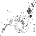
Fig. 2 shows an isometric exploded view of the end effector cuff as shown inFig. 1 ; -
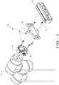
Fig. 3 shows an isometric view of the robotic system ofFig. 1 as assembled; and -
Fig. 4 illustrates another embodiment of a robotic system in which the end effector attaches directly to the end effector cuff. - Corresponding reference characters indicate corresponding parts throughout the several views. The exemplifications set out herein illustrate embodiments of the invention and such exemplifications are not to be construed as limiting the scope of the invention in any manner.
- Referring now to the drawings, and more particularly to
Figs. 1-3 , there is shown arobotic system 10 which generally includes arobot 12, anend effector cuff 14, anoptional transition plate 16, and anend effector 18. - The
robot 12 may be in the form of any desiredrobot 12. Therobot 12 may be a single or multi-axis robot, including a Cartesian robot, a SCARA robot, a collaborative and/or an industrial robot. In the present embodiment, therobot 12 is in the form of acollaborative robot 12, which may be used in collaboration with a human worker. Therobot 12 may include force and/or power limiting features such that therobot 12 may sense abnormal forces and stop or reverse its action. Therobot 12 may also substantially cover its internal systems and may have rounded surfaces. Therobot 12 may also include an electrical power supply and an electrical connector which are configured for connecting to and supplying electrical power to theend effector cuff 14 and/or theend effector 18. - The
end effector cuff 14 is connected to therobot 12. Theend effector cuff 14 may be configured for adapting theend effector 18 to therobot 12 and/or for housing the necessary components for operating theend effector 18. Theend effector cuff 14 may include one or more fluid inlet(s) 20 with accompanying inlet fitting(s) 22, afluid exhaust 24, and electrical hardware 26 (Fig. 2 ). Theend effector cuff 14 may also include fluid port(s) 28 to couple with fluid valve(s) 30 integrated into theend effector cuff 14. In the present embodiment, theend effector cuff 14 only has onefluid inlet 20 that feeds twofluid valves 30. - The
end effector cuff 14 may also include various mounting features and mounting geometry for physically and operably connecting to therobot 12. For example, theend effector cuff 14 may include all of the mounting features and mounting geometry between thecollaborative robot 12 and thepneumatic end effector 18, with or without an accompanyingtransition plate 16. Additionally, for example, theend effector cuff 14 may include a mountingspace 32, e.g. a cutout, groove, slot, depression, etc., that is configured to accommodate the electrical hardware 26 (Fig. 2 ). The back of thetransition plate 16 or theend effector 18 can enclose a front portion of the mountingspace 32. Further, the body of theend effector cuff 14 may include a recess R for housing and protecting the fluid valve(s) 30 (Fig. 2 ). The recess R may be in the form of a cutout which defines a back wall, a bottom wall, and an inner wall. The front portion of the recess R may be open such that when therobotic system 10 is assembled, the back of thetransition plate 16 or theend effector 18 forms a front wall to enclose the recess R. - The
end effector cuff 14 may be configured to accommodate numerous different types ofrobots 12. For example, theend effector cuff 14 may incorporate a universal, e.g. common, connection point in order to be compatible withnumerous robots 12. In this regard, theend effector cuff 14 is configured for being compatible with therobot 12 at its first end, and theend effector 18 is configured for being compatible with theend effector cuff 14 and/or thetransition plate 16 at its second end. The body of theend effector cuff 14 may correspond to the body of therobot 12. For instance, the body of theend effector cuff 14 may be circular and its outer diameter may match the diameter of the circular end of therobot 12. Theend effector cuff 14 may be mounted to therobot 12 by one ormore fasteners 34. Theend effector cuff 14 may be composed of any desired material including a metal, a metal alloy, and a plastic material. - The
electrical hardware 26 is configured for coupling to therobot 12 and controlling the fluid flow, end effector controls, and/or the operation of therobot 12 itself. Theelectrical hardware 26 may include one or more electrical connector(s) 36 that electrically couple to therobot 12 and an electronic control unit (ECU) 38 that couples to the electrical connector(s) 36 (Fig. 2 ). Theelectrical connector 36 and theECU 38 are each housed within the mountingspace 32 in the body of theend effector cuff 14. Theelectrical connector 36 may be in the form of any known connector. For example, theelectrical connector 36 may be in the form of or similar to a Lumberg connector. TheECU 38 is operably coupled to therobot 12 via theelectrical connector 36. TheECU 38 may be operably coupled to thefluid valves 30 and/or to theend effector 18. TheECU 38 may include software and various other hardware, including a circuit board, in order to control therobot 12, the fluid valve(s) 30, and/or theend effector 18. For example, the ECU may control the end effector proximity switches and feedback. - The fluid port(s) 28 may be fluidly coupled to the fluid inlet(s) 20 via internal conduits within the body of the
end effector cuff 14. Thefluid ports 28 may be in the form of receivingholes 28, which receive and couple to the fluid valve(s) 30. Thefluid ports 28 may be positioned inwardly from the outer periphery of theend effector cuff 14, in order to provide an internal space to accommodate the fluid valve(s) 30. In more detail, a portion of the outer periphery of theend effector cuff 14 may be cut out such that the recess R is formed. Thefluid ports 28 may be located on the inner wall of the recess R so that at least a portion of the fluid valve(s) 30 are housed within the recess R. For instance, the entire body of eachfluid valve 30 may be positioned within the recess R (Fig. 1 ). - The
fluid valves 30 may be in the form ofpneumatic air valves 30, which can be operably connected to theend effector 18. The pneumatic air valve(s) 30 may be fed by, i.e., receive pressurized air from, thefluid inlet 20 by way of the fluid port(s) 28. The pneumatic air valve(s) 30 may be in the form of any known pneumatic valve(s), including 24 VDC MAC® Bullet Valves®. - The
transition plate 16 may be connected in between theend effector cuff 14 and theend effector 18. Thetransition plate 16 operably connects theend effector 18 to theend effector cuff 14. Thetransition plate 16 may be uniquely designed to accommodate theend effector 18. In other words, thetransition plate 16 is configured for efficiently connecting theend effector 18 to therobot 12 by way of being compatible with theend effector cuff 14. In this regard, theend effector 18 is capable of being integrated into numerous types ofrobots 12 via thetransition plate 16 and theend effector cuff 14. Thetransition plate 16 may be mounted to theend effector cuff 14 and to theend effector 18 by knownfasteners 34. Thetransition plate 16 may be composed of any suitable material including a metal or plastic material. It is conceivable to not include atransition plate 16 such that theend effector 18 may directly mount to theend effector cuff 14 via known fasteners. - The
end effector 18 may be connected to thetransition plate 16. Theend effector 18 may be in the form of apneumatic end effector 18. As theelectrical hardware 26 andfluid valves 30 are integrated into theend effector cuff 14, the fluid and the electrical power which operate theend effector 18 may be provided by theend effector cuff 14. In this regard, therobotic system 10 of the present invention greatly reduces or eliminates externally mounted pneumatic tubing and electrical wiring. Theend effector 18 may be mounted to thetransition plate 16 by knownfasteners 34. - Referring now to
Fig. 4 , there is shown another embodiment of therobotic system 40, which is the same as therobotic system 10 as described above except therobotic system 40 does not include atransition plate 16. Thereby, theend effector 18 may be directly connected to theend effector cuff 14 via known fasteners. - In a or in the preferred embodiment and as disclosed above, a robotic system includes a robot and an end effector cuff connected to the robot. The end effector cuff has a body and includes at least one fluid inlet, at least one fluid port fluidly connected to the at least one fluid inlet, at least one fluid valve fluidly connected to the at least one fluid port and housed within the body of the end effector cuff, and an electronic control unit operably coupled to the robot and housed within the body of the end effector cuff. The robotic system also includes an end effector connected to the end effector cuff.
- While this invention has been described with respect to at least one embodiment, the present invention can be further modified within the spirit and the scope of this disclosure. This application is therefore intended to cover any variations, uses, or adaptations of the invention using its general principles. Further, this application is intended to cover such departures from the present disclosure as come within known or customary practice in the art to which this invention pertains.
Claims (15)
- A robotic system, comprising:a robot;an end effector cuff connected to the robot and having a body, said end effector cuff including:at least one fluid inlet;at least one fluid port fluidly connected to said at least one fluid inlet;at least one fluid valve fluidly connected to said at least one fluid port and housed within the body of the end effector cuff; andan electronic control unit operably coupled to the robot and housed within the body of the end effector cuff; andan end effector connected to the end effector cuff.
- The robotic system of claim 1, wherein said body of the end effector cuff has a recess configured for housing and protecting said at least one fluid valve and/or wherein said recess has an inner wall, and said at least one fluid port is located on said inner wall such that said at least one fluid valve is housed and protected within said recess and/or wherein said body of the end effector cuff has a mounting space configured for housing the electronic control unit.
- The robotic system of claim 1, wherein said at least one fluid inlet is in the form of only one fluid inlet.
- The robotic system of claim 3, wherein said at least one fluid port is in the form of two fluid ports.
- The robotic system of claim 4, wherein said at least one fluid valve is in the form of two fluid valves respectively fluidly connected to each said fluid port such that said fluid inlet feeds fluid to both of said fluid valves.
- The robotic system of claim 1, wherein said electronic control unit is configured for controlling said at least one fluid valve.
- The robotic system of claim 1, wherein said end effector cuff includes an electrical connector housed within the body of the end effector cuff, and said electrical connector is electrically coupled to the robot and to the electronic control unit such that the electronic control unit is operably coupled to the robot by way of said electrical connector.
- A robotic system according to one of the preceding claims, comprising:a transition plate connected to the end effector cuff;and/or wherein said end effector cuff is configured for being compatible with said robot and said end effector is configured for being compatible with said transition plate such that said transition plate is configured for efficiently connecting the end effector to the robotand/or wherein said body of the end effector cuff has a mounting space configured for housing the electronic control unit.
- The robotic system of claim 8, wherein said body of the end effector cuff has a recess configured for housing and protecting said at least one fluid valve.
- The robotic system of claim 9, wherein said recess has an inner wall, and said at least one fluid port is located on said inner wall such that said at least one fluid valve is housed and protected within said recess.
- The robotic system of claim 8, wherein said at least one fluid inlet is in the form of only one fluid inlet, and said at least one fluid port is in the form of two fluid ports.
- The robotic system of claim 11, wherein said at least one fluid valve is in the form of two fluid valves respectively fluidly connected to each said fluid port such that said fluid inlet feeds fluid to both of said fluid valves.
- The robotic system of claim 8, wherein said end effector cuff includes an electrical connector housed within the body of the end effector cuff, and said electrical connector is electrically coupled to the robot and to the electronic control unit such that the electronic control unit is operably coupled to the robot by way of said electrical connector.
- An end effector cuff, preferably for a robotic system according to one of the preceding claims, having a body and comprising:at least one fluid inlet;at least one fluid port fluidly connected to said at least one fluid inlet;at least one fluid valve fluidly connected to said at least one fluid port and housed within the body of the end effector cuff; andan electronic control unit housed within the body of the end effector cuff,wherein said end effector cuff is configured for being compatible with different types of robots and said end effector cuff is configured for connecting an end effector to any one of said robots.
- The end effector cuff of claim 14, wherein said body of the end effector cuff has a recess configured for housing and protecting said at least one fluid valve and/or wherein said body of the end effector cuff has a mounting space configured for housing the electronic control unit.
Priority Applications (1)
| Application Number | Priority Date | Filing Date | Title |
|---|---|---|---|
| EP20155791.5A EP3670118A1 (en) | 2017-06-22 | 2018-06-05 | Robot end effector cuff |
Applications Claiming Priority (1)
| Application Number | Priority Date | Filing Date | Title |
|---|---|---|---|
| US201762523449P | 2017-06-22 | 2017-06-22 |
Related Child Applications (1)
| Application Number | Title | Priority Date | Filing Date |
|---|---|---|---|
| EP20155791.5A Division EP3670118A1 (en) | 2017-06-22 | 2018-06-05 | Robot end effector cuff |
Publications (2)
| Publication Number | Publication Date |
|---|---|
| EP3441205A2 true EP3441205A2 (en) | 2019-02-13 |
| EP3441205A3 EP3441205A3 (en) | 2019-07-31 |
Family
ID=62620656
Family Applications (2)
| Application Number | Title | Priority Date | Filing Date |
|---|---|---|---|
| EP20155791.5A Withdrawn EP3670118A1 (en) | 2017-06-22 | 2018-06-05 | Robot end effector cuff |
| EP18175941.6A Withdrawn EP3441205A3 (en) | 2017-06-22 | 2018-06-05 | Robot end effector cuff |
Family Applications Before (1)
| Application Number | Title | Priority Date | Filing Date |
|---|---|---|---|
| EP20155791.5A Withdrawn EP3670118A1 (en) | 2017-06-22 | 2018-06-05 | Robot end effector cuff |
Country Status (4)
| Country | Link |
|---|---|
| US (1) | US10780575B2 (en) |
| EP (2) | EP3670118A1 (en) |
| CA (1) | CA3005171A1 (en) |
| MX (1) | MX381565B (en) |
Cited By (5)
| Publication number | Priority date | Publication date | Assignee | Title |
|---|---|---|---|---|
| DE102019120116A1 (en) * | 2019-07-25 | 2021-01-28 | Beckhoff Automation Gmbh | Active and passive arm module, end module, robotic arm and industrial robot |
| WO2021089272A1 (en) * | 2019-11-07 | 2021-05-14 | J.Schmalz Gmbh | Vacuum manipulator |
| US12109694B2 (en) | 2019-07-25 | 2024-10-08 | Beckhoff Automation Gmbh | Industrial robot |
| US12208518B2 (en) | 2019-07-25 | 2025-01-28 | Beckhoff Automation Gmbh | Arm module, robotic arm and industrial robot |
| US12285860B2 (en) | 2019-07-25 | 2025-04-29 | Beckhoff Automation Gmbh | Arm module for a modular robotic arm of an industrial robot |
Families Citing this family (7)
| Publication number | Priority date | Publication date | Assignee | Title |
|---|---|---|---|---|
| DE102017009319C5 (en) * | 2017-10-09 | 2023-08-03 | Günther Zimmer | Adapter system for connecting the last link in a kinematic chain to a handling device |
| JP6930895B2 (en) * | 2017-10-30 | 2021-09-01 | ニッタ株式会社 | Automatic tool changer coupler and automatic tool changer |
| USD873878S1 (en) | 2018-01-17 | 2020-01-28 | Auris Health, Inc. | Robotic arm |
| USD932628S1 (en) | 2018-01-17 | 2021-10-05 | Auris Health, Inc. | Instrument cart |
| AT522542B1 (en) * | 2019-05-09 | 2022-07-15 | Facc Ag | Interchangeable coupling, changing device and testing and processing system |
| US11545806B2 (en) * | 2020-01-03 | 2023-01-03 | Aptiv Technologies Limited | Conductor assembly staging for robotic installation |
| GB2613658B (en) * | 2021-12-08 | 2024-02-21 | Impaqt Robotics Private Ltd | Pneumatic coupling system |
Citations (3)
| Publication number | Priority date | Publication date | Assignee | Title |
|---|---|---|---|---|
| US4815780A (en) * | 1987-03-30 | 1989-03-28 | Erowa Ag | Apparatus for detachably connecting a tool to a manipulating device |
| WO1995032078A1 (en) * | 1994-05-19 | 1995-11-30 | Brien Brian Jonathan O | Shape variable structure |
| DE202007013056U1 (en) * | 2007-09-10 | 2007-11-22 | Schunk Gmbh & Co. Kg Spann- Und Greiftechnik | Adapter system with an attachable to a handling element replaceable head and with an attachable to a tool adapter |
Family Cites Families (19)
| Publication number | Priority date | Publication date | Assignee | Title |
|---|---|---|---|---|
| US4545723A (en) | 1983-09-30 | 1985-10-08 | The United States Of America As Represented By The Administrator Of The National Aeronautics And Space Administration | Apparatus for adapting an end effector device remotely controlled manipulator arm |
| JPS6133881A (en) | 1984-07-27 | 1986-02-17 | 株式会社日立製作所 | Positioning device |
| US4693663A (en) * | 1984-10-05 | 1987-09-15 | Donaldson Company, Inc. | Robot with articulated arm |
| US4691419A (en) * | 1985-11-12 | 1987-09-08 | Rca Corporation | Robot end effector for processing component leads |
| US4883939A (en) | 1988-06-21 | 1989-11-28 | Automatic Tool Control And Management Systems, Inc. | Automatic tool changer for workpiece processing machines |
| DE19533948A1 (en) | 1994-09-14 | 1996-05-02 | Hans Gamerdinger | Energy distribution system for robotic tools |
| US5782571A (en) | 1996-10-17 | 1998-07-21 | Cpi Products, L.C. | Tool mount for automatic coupling with robotic equipment |
| DE10119356B4 (en) | 2001-04-20 | 2009-12-31 | Schunk Gmbh & Co. Kg Spann- Und Greiftechnik | Media feed device and swivel unit |
| US6893070B2 (en) | 2002-10-17 | 2005-05-17 | Delaware Capital Formation, Inc. | Integrated end effector |
| US7118452B2 (en) | 2004-02-12 | 2006-10-10 | The Boeing Company | Pneumatically actuated flexible coupling end effectors for lapping/polishing |
| US20090063807A1 (en) * | 2007-08-29 | 2009-03-05 | International Business Machines Corporation | Data redistribution in shared nothing architecture |
| JP5379457B2 (en) | 2008-11-27 | 2013-12-25 | Idec株式会社 | Robot hand |
| US8496425B2 (en) | 2008-12-05 | 2013-07-30 | GM Global Technology Operations LLC | Reconfigurable end-effectors with articulating frame and indexable master boom |
| JP2013212560A (en) * | 2012-04-02 | 2013-10-17 | Seiko Epson Corp | Robot system and robot |
| US9272421B2 (en) * | 2013-01-07 | 2016-03-01 | Milos Misha Subotincic | Visually controlled end effector |
| JP2016068202A (en) * | 2014-09-30 | 2016-05-09 | セイコーエプソン株式会社 | robot |
| US9630315B2 (en) | 2015-08-24 | 2017-04-25 | Rethink Robotics, Inc. | Robot with hot-swapped end effectors |
| JP6644531B2 (en) | 2015-12-01 | 2020-02-12 | 株式会社アイエイアイ | Wrist unit and robot |
| WO2017136429A1 (en) | 2016-02-01 | 2017-08-10 | AM Networks LLC | Desktop robotic arm with interchangeable end effectors |
-
2018
- 2018-05-15 US US15/979,647 patent/US10780575B2/en not_active Expired - Fee Related
- 2018-05-16 CA CA3005171A patent/CA3005171A1/en active Pending
- 2018-05-24 MX MX2018006413A patent/MX381565B/en unknown
- 2018-06-05 EP EP20155791.5A patent/EP3670118A1/en not_active Withdrawn
- 2018-06-05 EP EP18175941.6A patent/EP3441205A3/en not_active Withdrawn
Patent Citations (3)
| Publication number | Priority date | Publication date | Assignee | Title |
|---|---|---|---|---|
| US4815780A (en) * | 1987-03-30 | 1989-03-28 | Erowa Ag | Apparatus for detachably connecting a tool to a manipulating device |
| WO1995032078A1 (en) * | 1994-05-19 | 1995-11-30 | Brien Brian Jonathan O | Shape variable structure |
| DE202007013056U1 (en) * | 2007-09-10 | 2007-11-22 | Schunk Gmbh & Co. Kg Spann- Und Greiftechnik | Adapter system with an attachable to a handling element replaceable head and with an attachable to a tool adapter |
Cited By (7)
| Publication number | Priority date | Publication date | Assignee | Title |
|---|---|---|---|---|
| DE102019120116A1 (en) * | 2019-07-25 | 2021-01-28 | Beckhoff Automation Gmbh | Active and passive arm module, end module, robotic arm and industrial robot |
| US12109694B2 (en) | 2019-07-25 | 2024-10-08 | Beckhoff Automation Gmbh | Industrial robot |
| US12179346B2 (en) | 2019-07-25 | 2024-12-31 | Beckhoff Automation Gmbh | Active and passive arm module, end module and industrial robot |
| US12208518B2 (en) | 2019-07-25 | 2025-01-28 | Beckhoff Automation Gmbh | Arm module, robotic arm and industrial robot |
| US12285860B2 (en) | 2019-07-25 | 2025-04-29 | Beckhoff Automation Gmbh | Arm module for a modular robotic arm of an industrial robot |
| WO2021089272A1 (en) * | 2019-11-07 | 2021-05-14 | J.Schmalz Gmbh | Vacuum manipulator |
| CN114641379A (en) * | 2019-11-07 | 2022-06-17 | J.施迈茨有限公司 | Negative pressure operation equipment |
Also Published As
| Publication number | Publication date |
|---|---|
| CA3005171A1 (en) | 2018-12-22 |
| US10780575B2 (en) | 2020-09-22 |
| US20180370026A1 (en) | 2018-12-27 |
| EP3670118A1 (en) | 2020-06-24 |
| EP3441205A3 (en) | 2019-07-31 |
| MX2018006413A (en) | 2019-02-08 |
| MX381565B (en) | 2025-03-12 |
Similar Documents
| Publication | Publication Date | Title |
|---|---|---|
| US10780575B2 (en) | Robot end effector cuff | |
| WO2019231788A1 (en) | Modular platform for robotic end effector | |
| KR101949057B1 (en) | Robotic tool changer with tool stand decouple power supply | |
| JPH0329117Y2 (en) | ||
| US9604357B2 (en) | Robot and device having multi-axis motion sensor, and method of use thereof | |
| US4676142A (en) | Adapter with modular components for a robot end-of-arm interchangeable tooling system | |
| CN113646137B (en) | Processing modules for robots | |
| US11660766B2 (en) | Handling device | |
| US11491665B2 (en) | Tool exchange device | |
| KR20190120077A (en) | Rotary drive device and robot arm of a robot equipped therewith | |
| JP2020536756A (en) | Adapter system for connecting the last link of the kinematic chain to the handling device | |
| TW201700240A (en) | Electrical equipment attachment device and method | |
| US7689294B2 (en) | Systems, methods, and apparatus for providing continuous power to a fixture in a manufacturing process | |
| EP4074468A1 (en) | Air chuck | |
| US20190143509A1 (en) | Force Detecting Device And Robot System | |
| CN116277109B (en) | Multifunctional modular industrial robot | |
| CN219132358U (en) | Multifunctional modular industrial robot | |
| US11858125B2 (en) | Actuator and gripper head having an actuator | |
| JPH0825265A (en) | Automatic hand changer | |
| JPH0329118Y2 (en) | ||
| US20250033222A1 (en) | Pneumatic coupling system | |
| WO2025147906A1 (en) | An end effector for an industrial robot | |
| KR102669935B1 (en) | Hot-melt automatic supply robot automation system | |
| KR101871836B1 (en) | Vertical articulated robot equipped with vacuum ejector therewithin | |
| JP3172027B2 (en) | Automatic exchange device |
Legal Events
| Date | Code | Title | Description |
|---|---|---|---|
| PUAI | Public reference made under article 153(3) epc to a published international application that has entered the european phase |
Free format text: ORIGINAL CODE: 0009012 |
|
| STAA | Information on the status of an ep patent application or granted ep patent |
Free format text: STATUS: THE APPLICATION HAS BEEN PUBLISHED |
|
| AK | Designated contracting states |
Kind code of ref document: A2 Designated state(s): AL AT BE BG CH CY CZ DE DK EE ES FI FR GB GR HR HU IE IS IT LI LT LU LV MC MK MT NL NO PL PT RO RS SE SI SK SM TR |
|
| AX | Request for extension of the european patent |
Extension state: BA ME |
|
| PUAL | Search report despatched |
Free format text: ORIGINAL CODE: 0009013 |
|
| AK | Designated contracting states |
Kind code of ref document: A3 Designated state(s): AL AT BE BG CH CY CZ DE DK EE ES FI FR GB GR HR HU IE IS IT LI LT LU LV MC MK MT NL NO PL PT RO RS SE SI SK SM TR |
|
| AX | Request for extension of the european patent |
Extension state: BA ME |
|
| RIC1 | Information provided on ipc code assigned before grant |
Ipc: B25J 19/00 20060101AFI20190625BHEP Ipc: B25J 15/00 20060101ALI20190625BHEP Ipc: B25J 9/08 20060101ALI20190625BHEP Ipc: B25J 18/00 20060101ALI20190625BHEP |
|
| STAA | Information on the status of an ep patent application or granted ep patent |
Free format text: STATUS: REQUEST FOR EXAMINATION WAS MADE |
|
| 17P | Request for examination filed |
Effective date: 20200129 |
|
| RBV | Designated contracting states (corrected) |
Designated state(s): AL AT BE BG CH CY CZ DE DK EE ES FI FR GB GR HR HU IE IS IT LI LT LU LV MC MK MT NL NO PL PT RO RS SE SI SK SM TR |
|
| STAA | Information on the status of an ep patent application or granted ep patent |
Free format text: STATUS: EXAMINATION IS IN PROGRESS |
|
| 17Q | First examination report despatched |
Effective date: 20220530 |
|
| STAA | Information on the status of an ep patent application or granted ep patent |
Free format text: STATUS: THE APPLICATION IS DEEMED TO BE WITHDRAWN |
|
| 18D | Application deemed to be withdrawn |
Effective date: 20240103 |