KR20190120079A - Rotary drive device and robot arm of a robot equipped therewith - Google Patents
Rotary drive device and robot arm of a robot equipped therewith Download PDFInfo
- Publication number
- KR20190120079A KR20190120079A KR1020190042108A KR20190042108A KR20190120079A KR 20190120079 A KR20190120079 A KR 20190120079A KR 1020190042108 A KR1020190042108 A KR 1020190042108A KR 20190042108 A KR20190042108 A KR 20190042108A KR 20190120079 A KR20190120079 A KR 20190120079A
- Authority
- KR
- South Korea
- Prior art keywords
- drive
- unit
- rotary drive
- housing
- fluid
- Prior art date
Links
- 239000012530 fluid Substances 0.000 claims abstract description 98
- 238000000034 method Methods 0.000 claims description 14
- 238000005452 bending Methods 0.000 claims description 8
- 238000001514 detection method Methods 0.000 claims description 5
- 230000001105 regulatory effect Effects 0.000 claims description 5
- 230000001276 controlling effect Effects 0.000 claims 2
- 230000000149 penetrating effect Effects 0.000 claims 1
- 230000002093 peripheral effect Effects 0.000 description 21
- 230000033001 locomotion Effects 0.000 description 14
- 238000005192 partition Methods 0.000 description 7
- 238000004891 communication Methods 0.000 description 6
- 239000004020 conductor Substances 0.000 description 6
- 238000004519 manufacturing process Methods 0.000 description 4
- 238000005520 cutting process Methods 0.000 description 3
- 230000035515 penetration Effects 0.000 description 3
- 230000008878 coupling Effects 0.000 description 2
- 238000010168 coupling process Methods 0.000 description 2
- 238000005859 coupling reaction Methods 0.000 description 2
- 238000007789 sealing Methods 0.000 description 2
- 241000446313 Lamella Species 0.000 description 1
- 230000004913 activation Effects 0.000 description 1
- 230000004323 axial length Effects 0.000 description 1
- 230000008901 benefit Effects 0.000 description 1
- 230000008859 change Effects 0.000 description 1
- 238000004140 cleaning Methods 0.000 description 1
- 238000010276 construction Methods 0.000 description 1
- 230000007547 defect Effects 0.000 description 1
- 230000001419 dependent effect Effects 0.000 description 1
- 239000012636 effector Substances 0.000 description 1
- 230000000694 effects Effects 0.000 description 1
- 230000002687 intercalation Effects 0.000 description 1
- 238000009830 intercalation Methods 0.000 description 1
- 239000007788 liquid Substances 0.000 description 1
- 239000000463 material Substances 0.000 description 1
- 238000004806 packaging method and process Methods 0.000 description 1
- 230000010412 perfusion Effects 0.000 description 1
- 230000008569 process Effects 0.000 description 1
- 230000008439 repair process Effects 0.000 description 1
- 238000005096 rolling process Methods 0.000 description 1
- 230000011664 signaling Effects 0.000 description 1
- 238000000638 solvent extraction Methods 0.000 description 1
Images


Classifications
-
- F—MECHANICAL ENGINEERING; LIGHTING; HEATING; WEAPONS; BLASTING
- F15—FLUID-PRESSURE ACTUATORS; HYDRAULICS OR PNEUMATICS IN GENERAL
- F15B—SYSTEMS ACTING BY MEANS OF FLUIDS IN GENERAL; FLUID-PRESSURE ACTUATORS, e.g. SERVOMOTORS; DETAILS OF FLUID-PRESSURE SYSTEMS, NOT OTHERWISE PROVIDED FOR
- F15B13/00—Details of servomotor systems ; Valves for servomotor systems
- F15B13/02—Fluid distribution or supply devices characterised by their adaptation to the control of servomotors
- F15B13/04—Fluid distribution or supply devices characterised by their adaptation to the control of servomotors for use with a single servomotor
- F15B13/044—Fluid distribution or supply devices characterised by their adaptation to the control of servomotors for use with a single servomotor operated by electrically-controlled means, e.g. solenoids, torque-motors
- F15B13/0444—Fluid distribution or supply devices characterised by their adaptation to the control of servomotors for use with a single servomotor operated by electrically-controlled means, e.g. solenoids, torque-motors with rotary electric motor
-
- B—PERFORMING OPERATIONS; TRANSPORTING
- B25—HAND TOOLS; PORTABLE POWER-DRIVEN TOOLS; MANIPULATORS
- B25J—MANIPULATORS; CHAMBERS PROVIDED WITH MANIPULATION DEVICES
- B25J9/00—Programme-controlled manipulators
- B25J9/10—Programme-controlled manipulators characterised by positioning means for manipulator elements
- B25J9/14—Programme-controlled manipulators characterised by positioning means for manipulator elements fluid
- B25J9/146—Rotary actuators
-
- F—MECHANICAL ENGINEERING; LIGHTING; HEATING; WEAPONS; BLASTING
- F15—FLUID-PRESSURE ACTUATORS; HYDRAULICS OR PNEUMATICS IN GENERAL
- F15B—SYSTEMS ACTING BY MEANS OF FLUIDS IN GENERAL; FLUID-PRESSURE ACTUATORS, e.g. SERVOMOTORS; DETAILS OF FLUID-PRESSURE SYSTEMS, NOT OTHERWISE PROVIDED FOR
- F15B13/00—Details of servomotor systems ; Valves for servomotor systems
- F15B13/02—Fluid distribution or supply devices characterised by their adaptation to the control of servomotors
- F15B13/04—Fluid distribution or supply devices characterised by their adaptation to the control of servomotors for use with a single servomotor
- F15B13/0401—Valve members; Fluid interconnections therefor
-
- F—MECHANICAL ENGINEERING; LIGHTING; HEATING; WEAPONS; BLASTING
- F15—FLUID-PRESSURE ACTUATORS; HYDRAULICS OR PNEUMATICS IN GENERAL
- F15B—SYSTEMS ACTING BY MEANS OF FLUIDS IN GENERAL; FLUID-PRESSURE ACTUATORS, e.g. SERVOMOTORS; DETAILS OF FLUID-PRESSURE SYSTEMS, NOT OTHERWISE PROVIDED FOR
- F15B15/00—Fluid-actuated devices for displacing a member from one position to another; Gearing associated therewith
- F15B15/08—Characterised by the construction of the motor unit
- F15B15/12—Characterised by the construction of the motor unit of the oscillating-vane or curved-cylinder type
-
- F—MECHANICAL ENGINEERING; LIGHTING; HEATING; WEAPONS; BLASTING
- F15—FLUID-PRESSURE ACTUATORS; HYDRAULICS OR PNEUMATICS IN GENERAL
- F15B—SYSTEMS ACTING BY MEANS OF FLUIDS IN GENERAL; FLUID-PRESSURE ACTUATORS, e.g. SERVOMOTORS; DETAILS OF FLUID-PRESSURE SYSTEMS, NOT OTHERWISE PROVIDED FOR
- F15B21/00—Common features of fluid actuator systems; Fluid-pressure actuator systems or details thereof, not covered by any other group of this subclass
- F15B21/08—Servomotor systems incorporating electrically operated control means
- F15B21/085—Servomotor systems incorporating electrically operated control means using a data bus, e.g. "CANBUS"
-
- B—PERFORMING OPERATIONS; TRANSPORTING
- B25—HAND TOOLS; PORTABLE POWER-DRIVEN TOOLS; MANIPULATORS
- B25J—MANIPULATORS; CHAMBERS PROVIDED WITH MANIPULATION DEVICES
- B25J9/00—Programme-controlled manipulators
- B25J9/08—Programme-controlled manipulators characterised by modular constructions
-
- F—MECHANICAL ENGINEERING; LIGHTING; HEATING; WEAPONS; BLASTING
- F15—FLUID-PRESSURE ACTUATORS; HYDRAULICS OR PNEUMATICS IN GENERAL
- F15B—SYSTEMS ACTING BY MEANS OF FLUIDS IN GENERAL; FLUID-PRESSURE ACTUATORS, e.g. SERVOMOTORS; DETAILS OF FLUID-PRESSURE SYSTEMS, NOT OTHERWISE PROVIDED FOR
- F15B2211/00—Circuits for servomotor systems
- F15B2211/70—Output members, e.g. hydraulic motors or cylinders or control therefor
- F15B2211/705—Output members, e.g. hydraulic motors or cylinders or control therefor characterised by the type of output members or actuators
- F15B2211/7058—Rotary output members
Abstract
Description
본 발명은 유체 작동식 (fluid-operated) 회전 드라이브를 갖는, 회전 드라이브 장치에 관한 것이며, 상기 회전 드라이브는 드라이브 하우징 (drive housing) 과, 그것과 관련하여, 상기 드라이브 하우징 안에 배열된 적어도 하나의 선회 피스톤 (pivoting piston) 에의 제어된 유체가압을 통해 상기 회전 드라이브의 주축 (main axis) 둘레로 비틀릴 수 있는 (can be twisted) 드라이브 유닛 (drive unit) 을 구비하고, 상기 선회 피스톤과 연결된 상기 드라이브 유닛의 드라이브 샤프트 (drive shaft) 는 상기 드라이브 하우징의 축방향 정면에서, 동력 취출을 가능하게 하는 드라이브 섹션 (drive section) 과 함께 상기 드라이브 하우징 밖으로 돌출하고, 상기 회전 드라이브 장치는 전기적으로 작동 가능한 적어도 하나의 제어밸브를 포함하는 제어밸브 배열체를 가지며, 상기 제어밸브 배열체는 제어-유체 채널 시스템을 통하여, 상기 드라이브 하우징 안에서 상기 선회 피스톤에 의해 서로 분리된, 상기 회전 드라이브의 2개의 제 1 및 제 2 드라이브 챔버들 (drive chambers) 에 유체적으로 연결되고, 상기 제어밸브 배열체는, 상기 드라이브 하우징에 대해 상대적으로 상기 드라이브 유닛을 비틀기 위해 그리고 회전적으로 포지셔닝하기 위해 상기 두 드라이브 챔버들에의 유체가압을 제어하기 위해 형성된다.The present invention relates to a rotary drive device having a fluid-operated rotary drive, the rotary drive comprising a drive housing and, in connection therewith, at least one pivot arranged in the drive housing. The drive unit having a drive unit that can be twisted about the main axis of the rotary drive through controlled fluid pressurization to a pivoting piston, the drive unit being connected to the pivoting piston A drive shaft of the drive shaft protrudes out of the drive housing together with a drive section for enabling power take-off, at the axial front of the drive housing, wherein the rotary drive device is at least one electrically operable; A control valve arrangement comprising a control valve, said control valve arrangement The sieve is fluidly connected to two first and second drive chambers of the rotary drive, separated from each other by the pivoting piston in the drive housing, via a control-fluid channel system, and the control A valve arrangement is formed to control the fluid pressurization into the two drive chambers to twist the drive unit relative to the drive housing and to position it rotationally.
본 발명은 또한, 암관절 (arm joint) 을 이용해 서로 상대적으로 선회 가능한 방식으로 서로 연결된 적어도 2개의 암부재 (arm members) 를 갖는, 로봇의 로봇암에 관한 것이다.The invention also relates to a robotic arm of a robot, having at least two arm members connected to each other in a pivotable manner relative to each other using arm joints.
앞서 언급한 의미에서 형성된 회전 드라이브 장치는 DE 20 2008 003 944 U1 로부터 알려져 있다. 그것은 유체 작동식 회전 드라이브를 포함하고, 상기 회전 드라이브는 드라이브 하우징과, 상기 드라이브 하우징에 대해 상대적으로 비틀릴 수 있는 드라이브 유닛을 구비한다. 상기 드라이브 유닛은, 앞으로 상기 드라이브 하우징 밖으로 돌출하는 드라이브 샤프트와, 상기 드라이브 하우징의 내부에서 회전 불가능하게 상기 드라이브 샤프트와 연결된, 각각 2개의 드라이브 챔버들을 서로 분할하는 2개의 선회 피스톤을 포함한다. 상기 드라이브 챔버들은 유체 호스들에 의해 형성된 제어-유체 채널 시스템을 통하여 제어밸브 배열체에 연결되고, 상기 제어밸브 배열체의 전기적 작동을 통해, 상기 드라이브 하우징에 대해 상대적인 상기 드라이브 유닛의 회전운동이 야기될 수 있도록 제어되어 압축공기로 가압될 수 있다.The rotary drive device formed in the above-mentioned sense is known from DE 20 2008 003 944 U1. It includes a fluid actuated rotary drive, the rotary drive having a drive housing and a drive unit that can be twisted relative to the drive housing. The drive unit includes a drive shaft protruding out of the drive housing forward and two pivoting pistons each partitioning two drive chambers, each of which is connected to the drive shaft in a rotatable manner within the drive housing. The drive chambers are connected to the control valve arrangement via a control-fluid channel system formed by fluid hoses, and through the electrical operation of the control valve arrangement, rotational movement of the drive unit relative to the drive housing is caused. Can be controlled and pressurized with compressed air.
DE 39 41 255 C2 로부터 마찬가지로 회전 드라이브 장치가 알려져 있고, 하지만 상기 회전 드라이브 장치에서는, 유체 작동식 회전 드라이브의 드라이브 샤프트가 단지 하나의 유일한 선회 피스톤과 함께 드라이브 유닛으로 통합되어 있다.A rotary drive device is likewise known from
DE 10 2010 013 617 B4 는 모듈식으로 구성된 로봇을 공개하고, 상기 로봇은 움직일 수 있는 로봇암을 구비하고, 상기 로봇암은 서로 상대적으로 움직일 수 있는 2개의 암부재를 서로 연결하는 적어도 하나의 암관절을 갖추고 있다. 상기 암관절은 전기적으로 작동 가능한 회전 드라이브를 포함하는 회전 드라이브 장치에 의해 형성되어 있다.DE 10 2010 013 617 B4 discloses a modular robot, said robot having a movable robot arm, said robot arm having at least one arm connecting two arm members movable relative to each other. Equipped with joints. The arm joint is formed by a rotary drive device comprising an electrically actuated rotary drive.
본 발명의 목적은, 특히 적어도 하나의 암관절을 구비하는 로봇암을 실현하기 위해서도 적합한, 콤팩트하게 그리고 무게를 줄이도록 구성된 회전 드라이브 장치를 만들어내는 것이다.It is an object of the present invention to produce a rotary drive device which is compactly and reduced in weight, which is particularly suitable for realizing a robot arm with at least one arm joint.
이 목적을 달성하기 위해, 도입부에서 언급된 특징들과 관련된 회전 드라이브 장치에 있어서, 회전 드라이브는, 단일하게 핸들링 가능한 드라이브 어셈블리 (drive assembly) 의 구성요소로서 형성되고, 상기 드라이브 어셈블리는 상기 회전 드라이브 외에도, 드라이브 하우징의 축방향 정면과 마주 대한 축방향 뒷면에서 축방향에서 잇따라 배열된, 적어도 다음의 구성요소들을 포함하는 것이 제공된다:To achieve this object, in a rotary drive device in connection with the features mentioned in the introduction, the rotary drive is formed as a component of a single handleable drive assembly, the drive assembly being in addition to the rotary drive. It is provided to include at least the following components, arranged axially one after the other in an axial back face opposite the axial front face of the drive housing:
- 제어밸브 배열체를 떠받치는 밸브 지지 장치를 포함하고,A valve support device for holding the control valve arrangement,
- 공압식 (pneumatic) 연결유닛을 포함하고, 상기 공압식 연결유닛은, 밖으로부터 접근 가능한 방식으로, 외부 압력원과 연결 가능한 또는 연결된 급기 포트와, 압력싱크 (pressure sink) 와 연결 가능한 또는 연결된 배기 포트를 구비하고, 상기 제어밸브 배열체는 상기 급기 포트와 연결될 뿐만 아니라 상기 배기 포트와도 연결되고,A pneumatic connecting unit, said pneumatic connecting unit being connected to or connected to an external pressure source and an exhaust port connectable or connected to a pressure sink in an accessible manner from the outside; And the control valve arrangement is connected not only to the air supply port but also to the exhaust port,
- 상기 제어밸브 배열체와 그것의 전기적 액추에이팅을 위해 전기적으로 연결된 전자적 제어유닛을 포함한다.An electronic control unit electrically connected for the control valve arrangement and its electrical actuation.
본 발명에 따른 로봇의 로봇암은, 2개의 암부재를 서로 상대적으로 선회 가능한 방식으로 서로 연결하는 적어도 하나의 암관절을 포함하고, 상기 암관절은 앞서 언급한 의미에서 형성된 회전 드라이브 장치에 의해 형성되고, 드라이브 샤프트의 드라이브 섹션과 상기 유체 작동식 회전 드라이브의 드라이브 하우징은 각각 상기 로봇암의 상기 암부재들 중 하나를 고정시키기 위한 고정 인터페이스를 구비한다.The robot arm of the robot according to the present invention comprises at least one arm joint connecting two arm members to each other in a relatively pivotable manner, wherein the arm joint is formed by a rotary drive device formed in the above-mentioned sense. And the drive section of the drive shaft and the drive housing of the fluid actuated rotary drive each have a securing interface for securing one of the arm members of the robot arm.
이러한 방식으로, 모듈식으로 구성된, 단일하게 핸들링 가능한 드라이브 어셈블리를 구비하는 회전 드라이브 장치가 존재하고, 상기 드라이브 어셈블리 안에는 축방향에서 잇따라, 즉 상기 회전 드라이브의 주축의 축방향에서 잇따라, 다수의 기능관련 구성요소들이 나란히 늘어서고, 서로 고정된다. 상기 드라이브 어셈블리는 주요 구성요소로서, 드라이브 하우징을 갖는 그리고 그것과 관련하여 제어된 유체가압을 통해 회전적으로 움직일 수 있는 그리고 회전적으로 포지셔닝될 수 있는 드라이브 유닛을 갖는, 유체 작동식 회전 드라이브를 포함한다. 상기 드라이브 유닛의 축방향 정면에서는, 동력 취출을 가능하게 하는 상기 드라이브 유닛의 드라이브 샤프트의 드라이브 섹션이 돌출하는 반면, 상기 드라이브 하우징의 축방향 뒷면에서는 축방향에서 잇따라, 제어밸브 배열체를 떠받치는 적어도 하나의 밸브 지지 장치와, 공압식 연결유닛과, 전자적 제어유닛이 배열된다.In this way, there is a rotary drive device having a modularly configured, single handleable drive assembly, in which the drive assembly is successively in the axial direction, ie in the axial direction of the main axis of the rotary drive. The components are lined up side by side and fixed together. The drive assembly comprises, as a main component, a fluid actuated rotary drive having a drive housing and a drive unit that is rotatable and rotationally positioned via controlled fluid pressurization with respect thereto. At the axial front of the drive unit, the drive section of the drive shaft of the drive unit, which enables power take-off, protrudes, while at the axial back of the drive housing successively in the axial direction, at least supporting the control valve arrangement. One valve support device, a pneumatic connection unit and an electronic control unit are arranged.
상기 밸브 지지 장치는, 상기 회전 드라이브의 액추에이팅을 위해 필요한 상기 제어밸브 배열체를 떠받치고, 상기 제어밸브 배열체는 제어-유체 채널 시스템을 통하여, 선회 피스톤에 의해 서로 분리된 상기 회전 드라이브의 상기 드라이브 챔버들과 연결된다. 상기 공압식 연결유닛은, 상기 회전 드라이브의 작동을 위해 사용되는, 특히 압축공기인, 유체적 압력매체의 공급 및 배출을 위한 인터페이스들을 규정하고, 이를 위해 급기 포트와 배기 포트를 갖추고 있다. 이 포트들은 특히, 상기 포트들이 각각 하나의 유체라인의 탈착 가능한 연결을 가능하게 하도록 형성된다. 상기 공압식 연결유닛에서의 개념 “공압식”은 모든 종류의 압력유체를 이용한 사용을 위해 대표적이라고 이해되어야 하고, 압축공기로 제한되지 않는다. 상기 드라이브 어셈블리의 내부에서, 상기 급기 포트와 상기 배기 포트는 상기 제어밸브 배열체와 연결된다. 상기 제어밸브 배열체는 전기적으로 상기 전자적 제어유닛과 커플링되고, 상기 전자적 제어유닛은 상기 제어밸브 배열체의 작동을 위해 필요한 제어신호들을 발생시킨다. 모든 구성요소들은 특히 자체 지지하는 (self-supporting) 드라이브 어셈블리로 통합되고, 따라서 콤팩트한 그리고 무게를 줄이는 (weight-saving) 유닛 (unit) 이 존재한다. 게다가, 상기 드라이브 어셈블리의 상기 개별적인 구성요소들의 상기 축방향의 모듈식의 나란히 늘어섬은 상기 회전 드라이브의 주축을 가로지른 슬림한 구조를 보장한다.The valve support device supports the control valve arrangement required for actuating the rotary drive, the control valve arrangement being separated from one another by a pivoting piston via a control-fluid channel system. It is connected with the drive chambers. The pneumatic connection unit defines interfaces for the supply and discharge of a fluid pressure medium, in particular compressed air, which is used for the operation of the rotary drive, for which it is provided with an air supply port and an exhaust port. These ports are in particular formed such that the ports each allow a removable connection of one fluid line. The concept "pneumatic" in the pneumatic connection unit is to be understood as representative for use with all kinds of pressure fluids and is not limited to compressed air. Inside the drive assembly, the air supply port and the air exhaust port are connected to the control valve arrangement. The control valve arrangement is electrically coupled with the electronic control unit, and the electronic control unit generates control signals necessary for the operation of the control valve arrangement. All components are in particular integrated into a self-supporting drive assembly, so there is a compact and weight-saving unit. In addition, the axial modular side-by-side of the individual components of the drive assembly ensures a slim structure across the major axis of the rotary drive.
본 발명의 유리한 개선들은 종속항들에 나타나 있다.Advantageous improvements of the invention are indicated in the dependent claims.
바람직하게는, 상기 공압식 연결유닛은 축방향으로 상기 드라이브 하우징과 상기 밸브 지지 장치 사이에 배열된다. 하지만, 바뀐 차례가 마찬가지로 가능하다. 어쨌든, 상기 전자적 제어유닛이 상기 드라이브 어셈블리의 뒷쪽 폐쇄를 형성하면 유리하고, 따라서 상기 전자적 제어유닛에, 연결 조치들을 위해 매우 잘 접근 가능하다.Preferably, the pneumatic connecting unit is arranged between the drive housing and the valve support device in the axial direction. However, the changed turn is likewise possible. In any case, it is advantageous if the electronic control unit forms the rear closure of the drive assembly, and thus the electronic control unit is very well accessible for connection measures.
상기 밸브 지지 장치는 목적에 맞게 고정 스크루들 (fastening screws) 을 이용해 상기 드라이브 하우징에 고정된다. 이 고정 스크루들은 바람직하게는 상기 공압식 연결유닛도 관통하고, 그러므로 상기 공압식 연결유닛이 마찬가지로 고정된다.The valve support device is secured to the drive housing using fastening screws to suit the purpose. These fastening screws preferably also pass through the pneumatic connecting unit, so that the pneumatic connecting unit is likewise fixed.
상기 전자적 제어유닛은 목적에 맞게, 상기 드라이브 하우징과 축방향으로 마주 대한 상기 밸브 지지 장치의 뒷면에 배열된다. 상기 전자적 제어유닛은 목적에 맞게 상기 드라이브 하우징에 의존하지 않고 상기 밸브 지지 장치에 고정되고, 따라서 상기 전자적 제어유닛은, 예컨대 수리를 목적으로, 상기 밸브 지지 장치를 상기 드라이브 하우징에서 풀 필요없이 쉽게 제거될 수 있다.The electronic control unit is arranged on the rear side of the valve support device opposite the drive housing axially, as appropriate. The electronic control unit is fixed to the valve support device without depending on the drive housing for purpose, so that the electronic control unit can be easily removed without the need to unscrew the valve support device from the drive housing, for example for repair purposes. Can be.
상기 밸브 지지 장치는 바람직한 구현형태에서 채널 플레이트 (channel plate) 를 구비하고, 상기 채널 플레이트는 그것의 플레이트 평면이 상기 회전 드라이브의 주축에 대해 직각으로 정렬되도록 정렬된다. 이 채널 플레이트는 상기 드라이브 하우징의 상기 축방향 뒷면의 영역에 배열된다. 상기 제어-유체 채널 시스템은 상기 채널 플레이트 안에서 연장되고, 목적에 맞게 적어도 부분적으로 그것의 플레이트 평면에서 연장되고, 상기 제어밸브 배열체는 상기 채널 플레이트에 부착되고, 상기 채널 플레이트 안에서 연장되는 상기 제어-유체 채널 시스템과 연통한다 (communicate). 그러므로, 상기 드라이브 유닛의 작동을 위해 필요해진, 바람직하게는 압축공기인, 유체적 압력매체의 공급 및 배출은 상기 채널 플레이트를 관통하여 수행된다.The valve support device has a channel plate in a preferred embodiment, the channel plate being aligned such that its plate plane is aligned perpendicular to the major axis of the rotary drive. This channel plate is arranged in the region of the axial rear face of the drive housing. The control-fluid channel system extends in the channel plate, at least partially in its plate plane, suitably for the purpose, and the control valve arrangement is attached to the channel plate and the control- extends in the channel plate. Communicate with the fluid channel system. Therefore, the supply and discharge of the fluid pressure medium, which is preferably compressed air, which is necessary for the operation of the drive unit, is carried out through the channel plate.
상기 채널 플레이트는 목적에 맞게 여러 부분으로 형성되고, 각각 판 모양으로 형성된 2개의 채널 플레이트 몸체들을 구비하고, 상기 채널 플레이트 몸체들은 상기 주축에 대해 직각인 결합평면에서 서로 부착된다. 이 결합평면의 영역에서, 하나의 채널 플레이트 몸체 안에서 또는 두 채널 플레이트 몸체들 안에서 형성된 도랑 모양의 오목부들에 의해, 상기 제어-유체 채널 시스템의 구성요소가 실현된다. 상기 도랑 모양의 오목부들은 상기 판 모양의 채널 플레이트 몸체들의 제작시 매우 간단히 홈들 (grooves) 로서 모양이 만들어질 수 있고, 따라서 공간절약적 구성을 위하여, 매우 복잡한 채널연장들도 실현될 수 있다.The channel plate is formed in various parts according to the purpose, and has two channel plate bodies each formed in a plate shape, and the channel plate bodies are attached to each other at a coupling plane perpendicular to the main axis. In this region of the engagement plane, by means of the groove-shaped recesses formed in one channel plate body or in two channel plate bodies, the components of the control-fluid channel system are realized. The groove-shaped recesses can be shaped very simply as grooves in the fabrication of the plate-shaped channel plate bodies, so that very complex channel extensions can be realized for space-saving construction.
상기 밸브 지지 장치는 바람직하게는 다수의 밸브 수용컵들 (valve receiving cups) 도 포함하고, 상기 밸브 수용컵들은 각각 하나의 제 1 축방향 단부영역과 함께, 상기 드라이브 하우징을 넘어 방사상으로 돌출하는 상기 채널 플레이트의 가장자리 섹션의, 축방향으로 상기 드라이브 하우징을 향한 단부면에 고정되고, 상기 밸브 수용컵들은 각각 상기 제어밸브 배열체의 적어도 하나의 제어밸브를 수용한다. 각각의 밸브 수용컵은 예컨대 단지 하나의 유일한 제어밸브를 또는 서로 나란히 배치된 2개의 제어밸브를 포함할 수 있다. 각각의 밸브 수용컵은 상기 채널 플레이트로부터 시작하여 손가락 모양으로 그리고 자유단을 가지면서 상기 드라이브 하우징의 축방향 정면 쪽으로의 방향으로 연장되고, 특히 방사상으로 바깥쪽을 가리키는 상기 드라이브 하우징의 주변 (peripheral) 바깥둘레면의 영역에서 연장된다.The valve support device preferably also includes a plurality of valve receiving cups, the valve receiving cups each projecting radially beyond the drive housing, with one first axial end region. Secured to an end face axially toward the drive housing of an edge section of the channel plate, the valve receiving cups each receiving at least one control valve of the control valve arrangement. Each valve receiving cup may comprise, for example, only one unique control valve or two control valves arranged next to each other. Each valve receiving cup extends in the direction of the axial front of the drive housing starting from the channel plate and having a finger shape and having a free end, in particular the peripheral of the drive housing pointing radially outward. It extends in the area of the outer circumferential surface.
상기 채널 플레이트에서 가장자리쪽에서, 바람직하게는 다수의 밸브 수용컵들이 상기 회전 드라이브의 상기 주축 둘레로 분배되어 배열된다. 각각의 밸브 수용컵은 목적에 맞게 원호 모양의 (circular arc-shaped) 횡단면을 가지며, 그것의 오목한 쪽은 상기 회전 드라이브의 상기 주축을 향해 있다.On the edge of the channel plate, preferably a plurality of valve receiving cups are arranged distributed around the main axis of the rotary drive. Each valve receiving cup has a circular arc-shaped cross section suited to the purpose, the concave side of which is towards the main axis of the rotary drive.
각각의 밸브 수용컵은 바람직하게는 일체로 형성된다. 각각의 밸브 수용컵이 상기 채널 플레이트와 축방향으로 마주 대한 상기 밸브 수용컵의 제 2 축방향 단부영역에서, 적어도 하나의 관통부를 갖는 컵 바닥을 구비하면 유리하고, 상기 관통부를 관통하여, 액추에이팅을 위해 필요한 각각의 제어밸브와의 연결이 행해진다. 바람직하게는, 밖에서 상기 컵 바닥에 인쇄회로기판이 부착되고, 상기 밸브 수용컵 안에 배열된 각각의 제어밸브는 상기 컵 바닥의 상기 적어도 하나의 관통부를 관통하여 상기 인쇄회로기판과 전기적으로 접촉된다.Each valve receiving cup is preferably integrally formed. It is advantageous if each valve receiving cup has a cup bottom with at least one penetration in the second axial end region of the valve receiving cup facing axially with the channel plate and penetrates the penetration. Connection is made with each control valve required for setting. Preferably, a printed circuit board is attached to the bottom of the cup from outside, and each control valve arranged in the valve receiving cup is in electrical contact with the printed circuit board through the at least one through part of the bottom of the cup.
적어도 하나의 밸브 수용컵의 내부공간은 목적에 맞게, 상기 채널 플레이트를 관통하여 연장되는 급기채널과 연통하고, 상기 급기채널은 상기 회전 드라이브 장치의 작동 동안 외부 압력원과, 특히 압축공기원과 연결되어 있다. 이러한 방식으로, 해당 밸브 수용컵 안에 배열된 모든 제어밸브들에 함께 유체적 압력매체가 공급된다. 이러한 밸브 수용컵을 급기 컵이라고도 부를 수 있다.The internal space of the at least one valve receiving cup is in communication with an air supply channel extending through the channel plate, as appropriate, which connects with an external pressure source, in particular with a compressed air source, during operation of the rotary drive device. It is. In this way, the fluid pressure medium is supplied together to all control valves arranged in the corresponding valve receiving cup. Such a valve receiving cup may also be called an air supply cup.
적어도 하나의 그 밖의 밸브 수용컵의 내부공간은 목적에 맞게, 상기 채널 플레이트를 관통하여 연장되는 배기채널과 유체연결되고, 상기 배기채널은 압력싱크와, 특히 대기와, 연결된다. 이러한 방식으로, 해당 밸브 수용컵 안에 배열된 모든 제어밸브들은 상기 압력싱크에 연결되고, 상기 유체 작동식 회전 드라이브의 할당된 드라이브 챔버의 배기를 수행할 수 있다.The interior space of the at least one other valve receiving cup is in fluid communication with an exhaust channel extending through the channel plate, as appropriate, with a pressure sink, in particular with the atmosphere. In this way, all control valves arranged in the corresponding valve receiving cup are connected to the pressure sink and can perform evacuation of the assigned drive chamber of the fluid operated rotary drive.
상기 전기적으로 작동 가능한 적어도 하나의 제어밸브는 바람직하게는 전기적으로 액추에이팅 가능한 피에조 밸브 (piezo valve) 이다. 각각의 피에조 밸브는 특히 제어요소로서의 적어도 하나의 벤딩 트랜스듀서 (bending transducer) 를 가지며, 상기 제어요소는 상기 드라이브 챔버들로의 그리고 상기 드라이브 챔버들로부터의 유체흐름을 제어한다. 하나의 동일한 피에조 밸브는 단지 하나의 유일한 제어요소를 또는 다수의 제어요소를 가질 수 있고, 이때 후자는 병렬 작동에 있어서 높은 유동률을 제어하는, 또는 각각의 제어요소를 상기 두 드라이브 챔버들 중 하나를 액추에이팅하기 위해 사용하는 가능성을 제공한다.The at least one electrically actuated control valve is preferably an electrically actuable piezo valve. Each piezo valve has in particular at least one bending transducer as a control element, which control the fluid flow to and from the drive chambers. One identical piezo valve may have only one unique control element or multiple control elements, where the latter controls a high flow rate in parallel operation, or each control element is connected to one of the two drive chambers. Provides the possibility to use for actuating.
벤딩 트랜스듀서를 갖춘 각각의 피에조 밸브는 목적에 맞게 세로 형태 (longitudinal shape) 를 가지며, 바람직하게는, 존재하는 전체 피에조 밸브들의 세로축들이 상기 회전 드라이브의 상기 주축에 대해 평행으로 정렬되도록 배열된다.Each piezo valve with a bending transducer has a longitudinal shape for the purpose and is preferably arranged such that the longitudinal axes of all the existing piezo valves are aligned parallel to the main axis of the rotary drive.
피에조 밸브들로서의 상기 제어밸브들의 구현형태는 간단한 방식으로, 비례 (proportional) 유체제어동작을 실현하는 유리한 가능성을 제공한다. 관류하기 위해 압축공기에 또는 다른 유체적 압력매체에 이용 가능한 자유 흐름횡단면은 이 경우 매우 편안히 액추에이팅 전압의 무단 (stepless) 변화를 통해 무단으로 조절될 수 있다.The implementation of the control valves as piezo valves offers the advantageous possibility of realizing a proportional fluid control operation in a simple manner. The free flow cross section available to the compressed air or other fluid pressure medium for perfusion can be adjusted steplessly through a stepless change in the actuating voltage in this case very comfortably.
특히 제어밸브 장치의 전기적으로 작동 가능한 적어도 하나의 제어밸브가 피에조 밸브로서 형성되면, 상기 전자적 제어유닛이 고볼트 스테이지 (high-volt stage) 를 구비하면 유리하고, 상기 고볼트 스테이지는 상기 제어밸브 배열체의 작동을 위해 필요한 고볼트-액추에이팅 전압을 제공하기 위해 형성된다. 그러므로, 상기 고볼트 스테이지는 상기 드라이브 어셈블리의 구성요소이기도 하다.In particular, if at least one electrically actuated control valve of the control valve device is formed as a piezo valve, it is advantageous if the electronic control unit has a high-volt stage, and the high bolt stage is arranged in the control valve arrangement. It is formed to provide the high bolt-actuating voltage needed for the operation of the sieve. Therefore, the high bolt stage is also a component of the drive assembly.
압전 (piezoelectric) 구조에 대해 대안적으로, 상기 제어밸브 배열체는 전자기식 구조를 가질 수도 있다. 이 두 구조의 혼합형태들도 가능하다.Alternatively to the piezoelectric structure, the control valve arrangement may have an electromagnetic structure. Mixed forms of these two structures are also possible.
상기 드라이브 어셈블리가 그 밖의 구성요소로서, 상기 드라이브 유닛의 회전각도를 파악하기 위해 형성된 엔코더 (encoder) 를 포함하면 유리하다. 상기 엔코더는 상기 드라이브 유닛의 회전위치와 관련된 회전위치 신호들을 공급하고, 상기 회전위치 신호들은 상기 회전 드라이브의 상기 드라이브 하우징과 관련된 상기 드라이브 유닛의, 회전각도에 따른 포지셔닝을 위한 근거로서 사용 가능하다. 상기 엔코더는 목적에 맞게 상기에서 언급된 전자적 제어유닛에 연결되고, 상기 전자적 제어유닛은 이 경우 엔코더 신호들을 평가하기 위해 그리고 처리 (process) 하기 위해 형성된다.It is advantageous if the drive assembly comprises, as another component, an encoder formed to know the angle of rotation of the drive unit. The encoder supplies rotational position signals associated with the rotational position of the drive unit, and the rotational position signals are available as a basis for positioning according to the rotational angle of the drive unit associated with the drive housing of the rotary drive. The encoder is connected to the above-mentioned electronic control unit for purpose, and the electronic control unit is in this case formed for evaluating and processing the encoder signals.
상기 엔코더는 목적에 맞게, 회전 불가능하게 상기 드라이브 샤프트에 배열된 그리고 이로써 상기 드라이브 샤프트의 회전운동을 함께 하는, 움직일 수 있는 엔코더 유닛 (encoder unit) 과, 비접촉으로 이 움직일 수 있는 엔코더 유닛과 함께 작용하는, 상기 밸브 지지 장치에 고정된, 고정형 (stationary) 엔코더 유닛을 포함한다. 상기 전자적 제어유닛은 이 경우 상기 고정형 엔코더 유닛에 전기적으로 연결된다.The encoder works with a movable encoder unit and a non-contactable movable encoder unit, which are arranged on the drive shaft in a non-rotatable manner, thereby co-rotating the drive shaft. And a stationary encoder unit fixed to the valve support device. The electronic control unit is in this case electrically connected to the fixed encoder unit.
목적에 맞게, 상기 전자적 제어유닛은 전자적 부품들이 갖춰진 인쇄회로기판을 포함하고, 상기 인쇄회로기판은 상기 주축에 대해 직각인 평면에서 연장되고, 상기 인쇄회로기판은 중앙 관통부를 가지며, 상기 중앙 관통부는 상기 엔코더에 의해 관통된다.To suit the purpose, the electronic control unit comprises a printed circuit board equipped with electronic components, the printed circuit board extending in a plane perpendicular to the main axis, the printed circuit board having a central through portion, and the central through portion It is penetrated by the encoder.
상기 드라이브 어셈블리의 상기 전자적 제어유닛은 바람직하게는 전자적 인터페이스 장치를 갖추고 있고, 상기 전자적 인터페이스 장치는 상위 전자적 제어장치와 연결된, 특히 직렬 버스 시스템의 연결을 가능하게 한다. 이 상위 전자적 제어장치는 상기 드라이브 어셈블리의 구성요소가 아니고, 그것에서 떨어져 배열된다. 상기 상위 전자적 제어장치는, 상기 유체 작동식 회전 드라이브의 작동을 그 밖의 장비들과, 예컨대 하나 또는 다수의 그 밖의 유체 작동식 회전 드라이브들과, 조율 (coordinate) 할 수 있다. 후자는 특히, 다수의 회전 드라이브 장치들이 암관절들로서 로봇의 로봇암 안에 통합되면 유리하다.The electronic control unit of the drive assembly is preferably equipped with an electronic interface device, which enables the connection of a higher level electronic control device, in particular a serial bus system. This upper electronic control is not a component of the drive assembly but is arranged away from it. The upper electronic control device can coordinate the operation of the fluid operated rotary drive with other equipment, such as one or more other fluid operated rotary drives. The latter is particularly advantageous if a number of rotary drive devices are integrated into the robot arm of the robot as arm joints.
상기 회전 드라이브 장치는 특히 모든 직렬 버스 시스템으로, 예컨대 이른바 “CAN Bus”으로 또는 이른바 이더넷 (Ethernet) 으로 작동될 수 있다.The rotary drive device can in particular be operated with any serial bus system, such as a so-called “CAN Bus” or so-called Ethernet.
상기 드라이브 유닛의, 회전각도에 따른 포지셔닝은 목적에 맞게, 상기 두 드라이브 챔버들 안에 만연한 유체압력의 압력조절을 근거로 수행된다. 이를 위해, 상기 회전 드라이브에 압력파악장치가 배열되면 유리하고, 상기 압력파악장치는 상기 드라이브 어셈블리의 구성요소이기도 하고, 상기 두 드라이브 챔버들 안으로 통하는 압력파악 채널들을 통하여, 상기 드라이브 챔버들 안에 만연한 유체압력을 파악할 수 있다. 상기 압력파악장치는 전기적으로 상기 전자적 제어유닛과 연결되고, 상기 전자적 제어유닛에, 검출된 압력신호들이 공급되고, 상기 전자적 제어유닛은, 상기 전자적 제어유닛의 압력조절유닛 안에 저장된 알고리즘을 근거로, 원하는 압력조절을 수행할 수 있다.Positioning of the drive unit in accordance with the rotational angle is carried out on the basis of the pressure regulation of the prevailing fluid pressure in the two drive chambers, depending on the purpose. To this end, it is advantageous if a pressure catcher is arranged in the rotary drive, the pressure catcher is also a component of the drive assembly, and fluid prevails in the drive chambers through pressure catching channels leading into the two drive chambers. Know the pressure. The pressure grasping device is electrically connected to the electronic control unit, the detected pressure signals are supplied to the electronic control unit, and the electronic control unit is based on an algorithm stored in the pressure regulating unit of the electronic control unit, Desired pressure adjustments can be made.
상기 드라이브 챔버들과 상기 제어밸브 배열체 사이의 연결을 생성하는 상기 제어-유체 채널 시스템은 목적에 맞게 그것의 전체에 있어서 호스 (hose) 라인들 및 관 라인들의 사용 없이 상기 드라이브 어셈블리의 내부에 형성된다. 이를 통해, 외부 기계적 영향들에 의한 상기 제어-유체 채널 시스템의 손상을 방지하며 특히 콤팩트한 크기가 생긴다.The control-fluid channel system for creating a connection between the drive chambers and the control valve arrangement is formed within the drive assembly without the use of hose lines and pipe lines in its entirety for purpose. do. This prevents damage of the control-fluid channel system by external mechanical influences and in particular a compact size.
목적에 맞게, 상기 제어밸브 배열체의 각각의 제어밸브는 적어도 부분적으로, 상기 주축과 관련하여 방사상으로 바깥쪽을 가리키는, 상기 회전 드라이브의 상기 드라이브 하우징의 주변 바깥둘레면의 영역에 배열된다. 상기 제어밸브 배열체가 다수의 제어밸브를 포함하면, 이 다수의 제어밸브는 특히 서로 동일한 방식으로 상기 드라이브 하우징의 상기 주변 바깥둘레면의 영역에 배치된다.For the purpose, each control valve of the control valve arrangement is arranged at least partially in the region of the peripheral outer circumferential surface of the drive housing of the rotary drive, pointing radially outward with respect to the main axis. If the control valve arrangement comprises a plurality of control valves, the plurality of control valves are arranged in the region of the peripheral outer circumferential surface of the drive housing, in particular in the same way.
본 발명에 따른 로봇암은 목적에 맞게 로봇의 구성요소이고, 충분한 개수의 암관절들을 갖추고 있고, 상기 암관절들은 각각 상기 로봇암의 2개의 암부재를 선회 가능한 방식으로 서로 연결한다. 각각의 암관절은 상기에서 여러 가지의 형태로 설명된 방식의 회전 드라이브 장치에 의해 형성되고, 따라서 서로 관절식으로 연결된 암부재들은 적용 특유적으로 서로 상대적으로 선회 가능하고, 각도에 따라 서로 상대적으로 포지셔닝될 수 있다. 상기 로봇암의 자유 단부에는, 상기 로봇암의 작동을 통해 포지셔닝될 수 있는 엔드 이펙터 (end effector), 예컨대 전기적으로 또는 유체력을 통해 작동 가능한 그립핑 장치 (gripping device) 가 안착한다. 상기 드라이브 섹션에뿐만 아니라 상기 회전 드라이브의 상기 드라이브 하우징에도, 상기 암관절을 통해 관절식으로 서로 연결되어야 하는 암부재들 중 하나를 고정시키기 위한 고정 인터페이스가 위치한다. 서로 관절식으로 연결된 상기 암부재들을 선회시키기 위한 구동력은, 상기 유체 작동식 회전 드라이브를 작동시키기 위해 사용되는 유체적 압력매체, 특히 압축공기를 통해 제공되는 유체력이다.The robot arm according to the present invention is a component of the robot according to the purpose, and has a sufficient number of arm joints, each of which connects the two arm members of the robot arm to each other in a pivotable manner. Each arm joint is formed by a rotary drive device in the manner described in various forms above, so that the arm members articulated with each other are pivotable relative to one another in application specific and relative to each other according to angle Can be positioned. At the free end of the robot arm is mounted an end effector, such as a gripping device operable electrically or through a fluid force, that can be positioned through operation of the robot arm. In the drive section, as well as in the drive housing of the rotary drive, a fixing interface is located for securing one of the arm members which must be articulated with the arm joint. The driving force for pivoting the arm members articulated with each other is a fluid force provided through a fluid pressure medium, in particular compressed air, used to actuate the fluid operated rotary drive.
이하, 본 발명은 첨부된 도면을 근거로 상세히 설명된다.Hereinafter, the present invention will be described in detail with reference to the accompanying drawings.
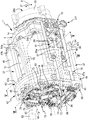
도 1 은 본 발명에 따른 회전 드라이브 장치의 바람직한 실시형태를 투시 후면도로 나타내고,
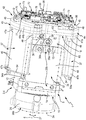
도 2 는 도 1 로부터의 회전 드라이브 장치를 다른 시각으로부터 그 밖의 투시도로 나타내고, 로봇암을 형성하기 위해 상기 회전 드라이브 장치에 고정된, 로봇암의 2개의 암부재의 단부섹션들이 일점쇄선으로 도시되고,
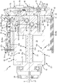
도 3 은 도 5 로부터의 절단선 III-III 에 따른 회전 드라이브 장치의 세로방향 단면을 나타내고,
도 4 는 도 5 로부터의 절단선 IV-IV 에 따른 회전 드라이브 장치의 그 밖의 세로방향 단면을 나타내고,
도 5 는 도 1 로부터의 절단선 V-V 에 따른 회전 드라이브 장치의 횡단면을 나타내고,
도 6 은 도 1 로부터의 절단선 VI-VI 에 따른 회전 드라이브 장치의 그 밖의 횡단면을 나타내고,
도 7 은 도 1 내지 도 6 으로부터의 회전 드라이브 장치의 아이소메트릭 분해도를 나타낸다.1 shows a preferred embodiment of a rotary drive device according to the invention in a perspective rear view,
FIG. 2 shows the rotational drive device from FIG. 1 in different perspectives from different perspectives, in which the end sections of the two arm members of the robotic arm, fixed to the rotational drive device to form a robotic arm, are shown in dashed line; ,
3 shows a longitudinal section of the rotary drive device according to cutting line III-III from FIG. 5,
FIG. 4 shows another longitudinal section of the rotary drive device according to cut line IV-IV from FIG. 5,
5 shows a cross section of the rotary drive device according to the cutting line VV from FIG. 1,
FIG. 6 shows a further cross section of the rotary drive device according to cutting line VI-VI from FIG. 1,
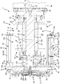
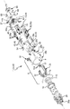
7 shows an isometric exploded view of the rotary drive device from FIGS. 1 to 6.
도면들은, 전체적으로 참조부호 1 로 표시된, 로봇의 로봇암의 섹션을 나타낸다. 로봇암 (1) 은 일점쇄선으로만 표시된 다수의 암부재 (2a, 2b) 를 가지며, 상기 암부재들은 항상 한 쌍씩 로봇암 (1) 의 암관절 (3) 에 의해 서로 연결된다. 암관절 (3) 은 회전 드라이브 장치 (4) 에 의해 형성되고, 상기 회전 드라이브 장치는 도면의 대부분의 그림들에서 암부재들 (2a, 2b) 없이 도시된다.The figures show a section of the robot arm of the robot, indicated generally by the
로봇암 (1) 안의 암관절 (3) 로서의 회전 드라이브 장치 (4) 의 사용은 특히 유리하며, 하지만 어떠한 경우에도 회전 드라이브 장치 (4) 의 유일한 사용 가능성을 나타내지는 않는다. 상기 회전 드라이브 장치는 임의의 적용들을 위해 사용될 수 있고, 상기 적용들은 2개의 구성요소를 서로 상대적으로 비틀고 그리고/또는 회전각도에 따라 포지셔닝하는 것에 관한 것이다. 예컨대, 회전 드라이브 장치 (4) 는 제조시설의 또는 포장기계의 2개의 기계부품을 비틀기 위해 그리고/또는 회전각도에 따라 포지셔닝하기 위해 사용될 수 있다. 이 열거는 최종적이지 않다.The use of the
회전 드라이브 장치 (4) 는 유체 작동식 회전 드라이브 (5) 를 포함한다. 상기 회전 드라이브는 압력하에 있는 구동유체를 사용하여 작동되고, 상기 구동유체는 액상이거나 또는 기체 상태일 수 있고, 상기 구동유체는 바람직하게는 압축공기이다. 바람직한 실시예의 설명은 압축공기를 이용한 작동을 근거로 행해진다.The
회전 드라이브 (5) 는, 하기에서 주축 (6) 이라 표시된 중앙 세로축을 갖는 세로방향 연장을 갖는다.The
회전 드라이브 (5) 는 드라이브 하우징 (7) 을 가지며, 상기 드라이브 하우징 안에 하우징 내부공간 (8) 이 형성된다. 주축 (6) 은 하우징 내부공간 (8) 의 중앙을 형성한다. 방사상으로 바깥쪽에서, 하우징 내부공간 (8) 은 주축 (6) 둘레로 연장되는, 드라이브 하우징 (7) 의 주변 측벽 (12) 에 의해 한정되고, 상기 주변 측벽은 목적에 맞게 원형 원통 모양의 외부윤곽을 갖는다.The
하우징 내부공간 (8) 은 목적에 맞게 원형 원통 모양으로 설계되고, 주축 (6) 에 대해 동축적으로 배열된다.The housing
서로 마주 대한 두 단부면에서, 하우징 내부공간 (8) 은 한편으로는 전방 폐쇄벽 (13) 에 의해 한정되고, 다른 한편으로는 드라이브 하우징 (7) 의 후방 폐쇄벽 (14) 에 의해 한정된다. 예시적으로, 주변 측벽 (12) 은 후방 폐쇄벽 (14) 과 일체로 형성되고, 따라서 컵 모양의 구조가 발생하고, 전방 폐쇄벽 (13) 은 그것과 관련하여 별도로 형성되고, 고정 스크루들 (fastening screws) 또는 다른 고정수단을 통해 주변 측벽 (12) 에 고정된다.On the two end faces facing each other, the housing
드라이브 하우징 (7) 은 전방 폐쇄벽 (13) 에 할당된 축방향 정면 (15) 과, 그것과 관련하여 마주 대한, 후방 폐쇄벽 (14) 에 할당된 축방향 뒷면 (16) 을 갖는다.The
드라이브 하우징 (7) 을 관통하여 동축적으로 회전 드라이브 (5) 의 드라이브 샤프트 (17) 가 연장되고, 이때 드라이브 샤프트 (17) 의 세로축은 주축 (6) 과 서로 같다. 드라이브 샤프트 (17) 는 드라이브 하우징 (7) 에 대해 상대적으로 회전축으로서의 주축 (6) 둘레로 비틀릴 수 있고, 이때 회전 지지를 위해 두 폐쇄벽 (13, 14) 에는 각각 하나의 베어링 장치 (18) 가 제공되고, 상기 베어링 장치는 특히 롤링 베어링 장치이다. 베어링 장치 (18) 를 통해 드라이브 샤프트 (17) 는 쉽게 비틀릴 수 있고, 동시에 주축 (6) 과 관련하여 방사상 및 축 방향에서 드라이브 하우징 (7) 에 대해 받쳐진다.The
드라이브 샤프트 (17) 는 드라이브 유닛 (22) 의 구성요소이고, 하우징 내부공간 (8) 안에 배열된 선회 피스톤 (23) 도 상기 드라이브 유닛에 속한다. 도 5 에서 볼 수 있는 바와 같이, 예컨대 상기 선회 피스톤이 내부 톱니부와 함께 드라이브 샤프트 (17) 의 외부 톱니부 위에 꽂힘으로써, 선회 피스톤 (23) 은 드라이브 샤프트 (17) 와 회전 불가능하게 연결된다.The
선회 피스톤 (23) 의 협력하에, 하우징 내부공간 (8) 은 유체 기밀식으로 제 1 드라이브 챔버 (24) 와 제 2 드라이브 챔버 (25) 로 분할된다. 제 1 작업채널 (working channel, A) 은 제 1 드라이브 챔버 (24) 안으로 통하고, 제 2 작업채널 (B) 은 제 2 드라이브 챔버 (25) 안으로 통하고, 보다 정확히 말하면 각각 내부 채널구멍 (26) 에 의해 통한다.In cooperation with the
바람직하게는, 두 내부 채널구멍들 (26) 은 후방 폐쇄벽 (14) 에 배열되고, 상기 후방 폐쇄벽은 두 작업채널 (A, B) 에 의해 특히 축방향에서 관통된다.Preferably, two inner channel holes 26 are arranged in the
회전축으로서의 주축 (6) 둘레로 드라이브 유닛 (22) 의, 이중 화살표에 의해 표시된 회전적 구동운동 (27) 을 야기하기 위해, 작업채널들 (A, B) 을 관통하여, 구동유체를 이용한 두 드라이브 챔버들 (24, 25) 에의 그리고 이로써 선회 피스톤 (23) 에의 제어된 유체가압이 가능하다. 회전방향은 두 드라이브 챔버들 (24, 25) 사이에 존재하는 압력차이를 통해 미리 정해진다. 같은 높이의 압력의 설정을 통해, 드라이브 유닛 (22) 은 드라이브 하우징 (7) 에 대해 상대적으로 모든 임의의 회전위치에서 비틀릴 수 없게 꽉 잡힐 수 있다.Two drives with drive fluid through the working channels A, B, in order to cause the
구동운동 (27) 은, 축방향 정면 (15) 에서 드라이브 하우징 (7) 밖으로 돌출하는 드라이브 샤프트 (17) 의 드라이브 섹션 (17a) 에서 취출될 수 있다.The
드라이브 섹션 (17a) 에 제 1 고정 인터페이스 (28a) 가 배열되고, 상기 제 1 고정 인터페이스에, 회전적으로 움직여져야 하는 구성요소가 고정될 수 있다. 예시적으로, 제 1 고정 인터페이스 (28a) 에, 두 암부재 (2a, 2b) 중 암부재 (2a) 가 고정된다.A
제 1 고정 인터페이스 (28a) 는 바로 드라이브 샤프트 (17) 에서 형성될 수 있고, 하지만 바람직하게는 별도의 인터페이스 몸체 (29) 의 구성요소이고, 상기 인터페이스 몸체는 드라이브 섹션 (17a) 에, 예컨대 나사결합을 통해, 고정된다.The first
구동운동 (27) 은 360도보다 작은 회전각도로 제한된다. 최대 회전각도는 예컨대 270도에 달한다. 구동운동 (27) 은 선택적으로 시계방향으로뿐만 아니라 시계반대방향으로도 방향지어질 수 있다.The
구동운동 (27) 을 야기하는 토크를 발생시키기 위해, 선회 피스톤 (23) 은 날개 섹션 (wing section, 23a) 을 가지며, 상기 날개 섹션은 주축 (6) 과 관련하여 방사상 방향에서 일측에서 드라이브 샤프트 (17) 로부터 떨어져 있다. 바람직하게는, 선회 피스톤 (23) 은, 드라이브 샤프트 (17) 에 의해 동축적으로 관통된 부시 섹션 (bush section, 23b) 도 가지며, 상기 부시 섹션은 상기에서 기술된 방식으로 회전 불가능하게 드라이브 샤프트 (17) 에 고정된다. 선회 피스톤 (23) 은 그것의 외면에 적어도 하나의 시일 (seal, 23c) 을 갖추고 있고, 상기 시일은 밀봉하에 슬라이딩할 수 있게, 하우징 내부공간 (8) 을 한정하는 드라이브 하우징 (7) 의 내면에 밀착한다.In order to generate the torque causing the
하우징 내부공간 (8) 안에서 날개 섹션 (23a) 옆에서 부시 섹션 (23b) 의 방사상 바깥둘레를 따라 연장되는 시일 (23c) 의 섹션은, 슬라이딩할 수 있게 분리벽 요소 (32) 와 밀봉접촉을 하고, 상기 분리벽 요소는 주축 (6) 에 대해 방사상 간격을 갖고 장소 고정적으로 (stationarily) 하우징 내부공간 (8) 안으로 삽입된다. 분리벽 요소 (32) 는 분리벽 시일 (32a) 에 의해 에워싸이고, 상기 분리벽 시일은 밖으로 선회 피스톤 (23) 의 시일 (23c) 에, 또한 주변 측벽 (12) 의 방사상 안둘레면 (12a) 에 그리고 두 폐쇄벽 (13, 14) 의 축방향 내면에 밀봉적으로 밀착한다. 이러한 방식으로, 분리벽 요소 (32) 와 선회 피스톤 (23) 은 함께 두 드라이브 챔버들 (24, 25) 을 한정하고, 상기 드라이브 챔버들은 하우징 내부공간 (8) 의 부분챔버들이다.The section of the
두 드라이브 챔버들 (24, 25) 에의 제어된 유체가압을 통해, 선회 피스톤 (23) 은 선회축으로서의 주축 (6) 을 갖는, 이중 화살표를 통해 시각화된 선회운동 (33) 을 하도록 구동될 수 있고, 이로부터 바로 상기 드라이브 섹션 (17a) 에서 취출 가능한 구동운동 (27) 이 발생한다.Through controlled fluid pressurization to the two
분리벽 요소 (32) 는 목적에 맞게, 선회 피스톤 (23) 의 최대 선회각도를 미리 정하기 위한 스톱 요소 (stop element) 로서도 기능을 수행한다. 이를 위해, 분리벽 요소 (32) 는 분리벽 시일 (32a) 의 양쪽에 주축 (6) 의 원주방향에서 떨어져 있는 스톱섹션들 (34) 을 가지며, 상기 스톱섹션들은 선회운동 (33) 의 방향에서 방향지어져 있고, 선회운동 (33) 의 2개의 서로 마주 대한 마지막 위치들을 미리 정하기 위해, 선회 피스톤 (23) 은 그것의 날개 섹션 (23a) 과 함께 상기 스톱섹션들에 부딪칠 수 있다. 두 스톱섹션들 (34) 을 통해, 선회 피스톤 (23) 의 최대 선회각도가 기계적으로 미리 정해지며, 상기 선회각도는 360도보다 작다.The
두 암부재 (2a, 2b) 중 다른 암부재 (2b) 를 고정시키기 위해, 밖에서 드라이브 하우징 (7) 에서, 특히 주변 측벽 (12) 의 외면에서, 제 2 고정 인터페이스 (28b) 가 형성된다. 상기 제 2 고정 인터페이스는 실시예에서 해당 암부재 (2b) 를 고정시키기 위한 다수의 고정구멍을 포함한다.In order to fix the
회전 드라이브 장치 (4) 의 다른 적용에서는, 제 2 고정 인터페이스 (28b) 에 임의의 기계부품이 부착될 수 있다.In other applications of the
두 드라이브 챔버들 (24, 25) 에의 제어된 유체가압을 위해, 회전 드라이브 장치 (4) 는 전기적으로 작동 가능한 제어밸브 배열체 (35) 를 갖추고 있다. 이 제어밸브 배열체 (35) 는 전기적으로 작동 가능한 적어도 하나의 제어밸브 (36) 를 포함하고, 제어밸브 배열체 (35) 가 이러한 전기적으로 작동 가능한 다수의 제어밸브 (36) 를 구비하면 목적에 맞고, 이는 도시된 실시예에 해당된다.For controlled fluid pressurization into both drive
제어밸브 배열체 (35) 는 제어-유체 채널 시스템 (37) 을 통하여 두 드라이브 챔버들 (24, 25) 에 유체적으로 연결되고, 상기 제어-유체 채널 시스템의 본질적인 구성요소들은 특히 도 6 에서 볼 수 있다. 두 작업채널 (A, B) 은 제어-유체 채널 시스템 (37) 에 속하고, 제어-유체 채널 시스템 (37) 의 각각 하나의 채널 단부 섹션을 형성한다.The
제어밸브 배열체 (35) 는 한편으로는 각각의 드라이브 챔버 (24, 25) 의 급기를 그리고 다른 한편으로는 배기를 제어할 수 있다. 상기 급기에 있어서는 해당 드라이브 챔버 (24, 25) 안으로의 구동유체의 공급이 수행되고, 상기 배기에 있어서는 구동유체는 해당 드라이브 챔버 (24, 25) 밖으로 압력해제를 위해 배출된다.The
제어밸브 배열체 (35) 는 또한 적어도 하나의 급기채널 (38) 을 통하여 급기 포트 (38a) 에 연결된다. 또한, 상기 제어밸브 배열체는 적어도 하나의 배기채널 (39) 을 통하여 배기 포트 (39a) 에 연결된다. 급기 포트 (38a) 와 배기 포트 (39a) 는 회전 드라이브 장치 (4) 의 외면에 위치하고, 이때 급기 포트 (38a) 는, 특히 압축공기원으로서 형성된, 압력원 (P) 과의 유체연결을 가능하게 하고, 배기 포트 (39a) 는, 특히 대기에 의해 형성된, 압력싱크 (R) 에 대한 유체연결을 가능하게 한다.The
두 포트 (38a, 39a) 는 목적에 맞게 호스 연결 장치들을 갖추고 있고, 상기 호스 연결 장치들은 각각, 압력원 (P) 으로 또는 압력싱크 (R) 로 안내하는 유체 호스의 탈착 가능한 연결을 가능하게 한다. 예시적으로, 포트들 (38a, 39a) 은 주축 (6) 에 대해 직각으로 방향지어진다.Both
제어밸브 배열체 (35) 는 회전 드라이브 (5) 의 드라이브 하우징 (7) 에 부착되고, 이러한 방식으로 회전 드라이브 (5) 와 함께, 단일하게 핸들링 가능한, 특히 자체 지지하는 드라이브 어셈블리 (42) 로 통합된다.The
목적에 맞게, 드라이브 어셈블리 (42) 는 밸브 지지 장치 (43) 도 포함하고, 상기 밸브 지지 장치에 제어밸브 배열체 (35) 가 바람직하게는 오로지 부착되고, 상기 밸브 지지 장치를 통하여 제어밸브 배열체 (35) 는 회전 드라이브 (5) 의 드라이브 하우징 (7) 에 고정된다.According to the purpose, the
바람직하게는, 각각의 제어밸브 (36) 는 밸브 지지 장치 (43) 에 고정되고, 따라서 상기 제어밸브는 상기 밸브 지지 장치에 의해 떠받쳐지고, 밸브 지지 장치 (43) 의 조정하에 장소 고정적으로 드라이브 하우징 (7) 과 관련하여 고정된다.Preferably, each control valve 36 is fixed to the
밸브 지지 장치 (43) 가, 제어-유체 채널 시스템 (37) 에 의해 그리고 바람직하게는 급기채널 (38) 과 배기채널 (39) 에 의해서도 관통된 채널 플레이트 (44) 를 구비하면 특히 유리하다고 증명되었고, 제어밸브 배열체 (35) 는 드라이브 하우징 (7) 에 의존하지 않고 상기 채널 플레이트에 고정된다.It has proved to be particularly advantageous if the
채널 플레이트 (44) 는 드라이브 하우징 (7) 의 축방향 뒷면 (16) 에 배열되고, 그것의 플레이트 평면이 주축 (6) 에 대해 직각으로 연장되도록 정렬된다.The
채널 플레이트 (44) 는, 드라이브 하우징 (7) 을 넘어 방사상으로 돌출하는 하나 또는 다수의 가장자리 섹션 (45) 을 가지며, 상기 가장자리 섹션들에서 각각 다수의 제어밸브 (36) 중 적어도 하나는, 상기 제어밸브가 채널 플레이트 (44) 안의 제어-유체 채널 시스템 (37) 과 유체적으로 연결되도록 고정된다.The
도시된 실시예에서 실현된 바람직한 실시형태에 따르면, 밸브 지지 장치 (43) 는 밸브 수용컵 (46) 이라 불리는 컵 모양의 다수의 구조를 포함하고, 상기 구조들은 각각 채널 플레이트 (44) 의 가장자리 섹션들 (45) 중 하나에 고정되고, 상기 구조들 안에 각각 제어밸브들 (36) 중 적어도 하나가 수용된다.According to a preferred embodiment realized in the illustrated embodiment, the
각각의 밸브 수용컵 (46) 은 제 1 축방향 단부영역 (47a) 에 고정 플랜지 (48) 를 가지며, 상기 고정 플랜지를 이용해 상기 밸브 수용컵은 축방향 정면 (15) 쪽으로의 방향을 가리키는 가장자리 섹션 (45) 의 전방 단부면에 밀봉하에 부착되고, 고정 스크루들 (49) 또는 다른 고정수단들의 도움으로 채널 플레이트 (44) 에, 특히 탈착 가능한 방식으로, 고정된다. 밸브 수용컵 (46) 은 단부면쪽에서 제 1 축방향 단부영역 (47a) 에서 원래부터 열려 있고, 조립된 상태에서는 채널 플레이트 (44) 의 가장자리 섹션 (45) 에 의해 폐쇄된다.Each
각각의 밸브 수용컵 (46) 은 채널 플레이트 (44) 로부터 손가락 모양으로 축방향 정면 (15) 쪽으로의 방향으로 멀리 돌출되고, 채널 플레이트 (44) 와 마주 대한 제 2 축방향 단부영역 (47b) 에서 자유단을 갖는다. 이 제 2 축방향 단부영역 (47b) 에서 밸브 수용컵 (46) 은 컵 바닥 (52) 을 가지며, 상기 밸브 수용컵은 제 1 축방향 단부영역 (47a) 에서는 열려 있다.Each
각각의 제어밸브 (36) 는 제 2 축방향 단부섹션 (53b) 과 함께 컵 바닥 (52) 의 내면에 지지되고, 이를 통해 상기 제어밸브의 마주 대한 제 1 단부섹션 (53a) 과 함께 채널 플레이트 (44) 에 내리눌려진다. 이러한 방식으로, 각각의 제어밸브 (36) 는 밸브 지지 장치 (43) 에 주축 (6) 의 축방향에서 움직일 수 없게 고정된다.Each control valve 36 is supported on the inner surface of the cup bottom 52 with a second
목적에 맞게, 컵 바닥 (52) 에는 하나 또는 다수의 관통부 (59) 가 마련되고, 상기 관통부를 관통하여 각각의 제어밸브 (36) 의 전기적 연결 접촉부들이 돌출하고, 상기 전기적 연결 접촉부들은, 밖에 컵 바닥 (52) 에 부착된 인쇄회로기판 (54) 과 접촉된다.For the purpose, the cup bottom 52 is provided with one or a plurality of
각각의 인쇄회로기판 (54) 은 적어도 하나의 전기기계식 인터페이스 장치 (54a) 를 가지며, 상기 전기기계식 인터페이스 장치는, 제어밸브들 (36) 을 작동에 따라 액추에이팅하기 위한 전기적 제어신호들을 공급하기 위해 형성된다.Each printed
각각의 제어밸브 (36) 는 특히 단부면쪽에서 그것의 제 1 축방향 단부섹션 (53a) 에 제어 가능한 하나 또는 다수의 밸브 개구부 (55) 를 가지며, 상기 밸브 개구부들은, 가장자리 섹션 (45) 의 후방 단부면에서 통하는 각각 하나의 연결채널 (56) 을 통하여, 채널 플레이트 (44) 안에서 연장되는 제어-유체 채널 시스템 (37) 과 연통한다.Each control valve 36 has one or more valve openings 55 controllable in its first
또한, 하기에서 급기 컵 (46a) 이라고도 불리는 적어도 하나의 밸브 수용컵 (46) 의 내부공간 (57) 은 급기 개구부 (38b) 를 통하여, 채널 플레이트 (44) 안에서 연장되는 급기채널 (38) 과 연결되고, 또한, 하기에서 배기 컵 (46b) 이라고도 불리는 적어도 하나의 그 밖의 밸브 수용컵 (46) 의 내부공간 (57) 은 배기 개구부 (39b) 를 통하여, 채널 플레이트 (44) 안에서 연장되는 배기채널 (39) 과 연결된다. 급기 개구부 (38b) 와 배기 개구부 (39b) 는 각각 밸브 수용컵 (46) 의 열린 제 1 축방향 단부영역 (47a) 의 영역에서, 축방향 정면 (15) 을 가리키는 채널 플레이트 (44) 의 단부면에서 통하고, 이로써 내부공간 (57) 과 직접적인 연결이 되어 있다.In addition, the
바람직한 도시된 실시예의 회전 드라이브 장치 (4) 는 하나의 급기 컵 (46a) 과 2개의 배기 컵 (46b) 을 포함한다. 이 개수는 변화할 수 있고, 이때 물론 각각의 컵 유형 중 적어도 하나가 존재한다.The
각각의 밸브 수용컵 (46) 의 내부공간 (57) 은 그것 안에 배열된 각각의 제어밸브 (36) 의 내부공간 (58) 과 지속적인 유체연결이 되어 있다. 각각의 제어밸브 (36) 는 그것의 내부공간 (58) 안에, 전기적 활성화를 통해 움직일 수 있는 적어도 하나의 제어요소 (62) 를 구비하고, 상기 제어요소는 움직일 수 있는 밸브부재 (62a) 에 작용하거나 또는 상기 밸브부재를 직접 형성한다. 할당된 제어 가능한 밸브 개구부 (55) 를 폐쇄하기 위해 또는 유체 통과를 가능하게 하기 위해 해제하기 위해, 상응하는 전기적 액추에이팅을 통해, 제어요소 (62) 의 위치 그리고 이로써 밸브부재 (62a) 의 위치가 변화될 수 있다.The
그러므로, 각각의 제어밸브 (36) 는, 제어-유체 채널 시스템 (37) 을 통하여 상기 제어밸브와 연결된 작업채널 (A 또는 B) 을, 할당된 밸브 수용컵 (46) 의 내부공간 (57) 으로부터 분리시키거나 또는 이 내부공간 (57) 과 연결시킬 수 있는데, 왜냐하면 이러한 방식으로, 급기 컵 (46a) 에 관한 것인지 또는 배기 컵 (46b) 에 관한 것인지의 여부에 의존하여, 할당된 작업채널 (A 또는 B) 을 그리고 이로써 그것에 연결된 드라이브 챔버 (24, 25) 를 선택적으로 급기하기 위해서, 배기하기 위해서, 또는 그것 안에 있는 구동유체를 감금하기 위해 차단하기 위해서이다.Therefore, each control valve 36 connects the working channel A or B connected with the control valve via the control-
제어-유체 채널 시스템 (37) 의 상응하는 설계를 통해, 하나의 동일한 밸브 수용컵 (46) 안에 포함된 다수의 제어밸브 (36) 를 동일한 작업채널 (A 또는 B) 에 연결하는, 하지만 또는 각각 하나의 제어밸브 (36) 를 제 1 작업채널 (A) 에 연결하고, 각각 다른 제어밸브 (36) 를 제 2 작업채널 (B) 에 연결하는 가능성이 존재한다. 상응하는 선택은 특히, 극복되어야 하는 유동률에 의존하여 행해진다.The corresponding design of the control-
채널 플레이트 (44) 는 목적에 맞게 주축 (6) 에 대해 직각인 결합평면 (63) 에서, 각각 판 모양으로 형성된 2개의 제 1 및 제 2 채널 플레이트 몸체 (44a, 44b) 로 분할된다. 제어-유체 채널 시스템 (37) 은 결합평면 (63) 에서 연장되고, 하나의 그리고/또는 다른 채널 플레이트 몸체 (44a, 44b) 안에 형성된 도랑 모양의 오목부들에 의해 형성되고, 상기 오목부들은 각각 다른 채널 플레이트 몸체 (44b, 44a) 에 의해 밀봉 마스크 (sealing mask, 64) 의 중간삽입하에 주변 쪽으로 밀봉된다.The
급기 포트 (38a) 와 배기 포트 (39a) 는 목적에 맞게 함께 공압식 연결유닛 (65) 에서 형성되고, 상기 공압식 연결유닛은 드라이브 하우징 (7) 의 축방향 뒷면 (16) 의 영역에 배열되고, 상기 공압식 연결유닛은 목적에 맞게 드라이브 어셈블리 (42) 의 구성요소이기도 하다. 상기 공압식 연결유닛은 예컨대 블록 모양의 몸체로 구성되고, 상기 몸체는 급기채널 (38) 에 의해 그리고 배기채널 (39) 에 의해 관통되고, 상기 몸체는, 밸브 수용컵들 (46) 의 내부공간들 (57) 중 적어도 하나와 함께 지속적으로 유체적으로 연결되어 있기 위해, 급기채널 (38) 뿐만 아니라 배기채널 (39) 도 채널 플레이트 (44) 안에서 계속되도록 채널 플레이트 (44) 에 부착된다.The
공압식 연결유닛 (65) 에서의 개념 “공압식”은 모든 종류의 압력유체를 이용한 사용을 위해 대표적이라고 이해되어야 하고, 압축공기로 제한되지 않는다. 이로써, 다만, 연결유닛 (65) 이 유체적 인터페이스를 형성한다는 것이 나타내져야 하고, 상기 유체적 인터페이스에서 구동유체는 회전 드라이브 장치 (4) 안으로 공급되거나 또는 그것 밖으로 배출된다.Concept in
공압식 연결유닛 (65) 은 도시되지 않은 실시예에서 채널 플레이트 (44) 와, 특히 두 채널 플레이트 몸체들 (44a, 44b) 중 하나와 일체로 형성된다.The
공압식 연결유닛 (65) 이 밸브 지지 장치 (43) 와 관련하여 별도의 구성요소이면 특히 유리하다고 간주되고, 이는 도시된 실시예에 해당된다.It is considered particularly advantageous if the pneumatic connecting
예시적으로, 공압식 연결유닛 (65) 은 주축 (6) 의 정렬과 관련하여 드라이브 하우징 (7) 의 후방 폐쇄벽 (14) 과 밸브 지지 장치 (43) 의 채널 플레이트 (44) 사이로 편입된다. 이는 밸브 지지 장치 (43) 의 그리고 특히 채널 플레이트 (44) 의, 회전 드라이브 (5) 로부터 축방향으로 멀리 향하는 뒷면 (66) 이 드라이브 어셈블리 (42) 의 그 밖의 구성요소들의 부착을 위해 이용 가능하다는 장점을 갖는다. 하지만 원칙적으로, 밸브 지지 장치 (43) 를 바로 드라이브 하우징 (7) 에 부착하고, 공압식 연결유닛 (65) 을 밸브 지지 장치 (43) 의 뒷면 (66) 에 배열하는 것이 전적으로 가능할 것이다.By way of example, the pneumatic connecting
두 드라이브 챔버들 (24, 25) 을 제어밸브 배열체 (35) 와 연결하는 제어-유체 채널 시스템 (37) 은, 호스 라인들 또는 관 라인들이 참여하지 않으면서, 목적에 맞게 그것의 전체에 있어서 드라이브 어셈블리 (42) 의 내부에 형성된다. 이는 손상을 방지하고, 외부 세척을 쉽게 하도록 한다. 또한, 드라이브 어셈블리 (42) 는 이러한 방식으로 상기 드라이브 어셈블리의 제작시 빨리 그리고 결함 없이 조립될 수 있다.The control-
제어밸브 배열체 (35) 의 각각의 제어밸브 (36) 는 목적에 맞게 적어도 부분적으로, 주축 (6) 과 관련하여 방사상으로 바깥쪽을 가리키는, 드라이브 하우징 (7) 의 주변 바깥둘레면 (67) 의 영역에 배열된다. 바람직하게는, 제어밸브들 (36) 은 각각 적어도 부분적으로 주변 측벽 (12) 을 따라 연장된다.Each control valve 36 of the
밸브 지지 장치 (43) 와 드라이브 하우징 (7) 사이로 편입된 공압식 연결유닛 (65) 을 근거로, 채널 플레이트 (44) 는 드라이브 하우징 (7) 에 대해 축방향 간격을 갖고 배열된다. 그러므로, 채널 플레이트 (44) 로부터 축방향 정면 (15) 쪽으로의 방향으로 멀리 돌출하는 제어밸브들 (36) 은 상기 제어밸브들의 제 1 축방향 단부섹션 (53a) 에 할당된 길이 섹션을 가지며, 상기 길이 섹션은 채널 플레이트 (44) 와 드라이브 하우징 (7) 사이의 축방향 간격을 따라 연장되고, 상기 길이 섹션에, 제어밸브 (36) 의 그 밖의 길이 섹션이 이어지고, 상기 그 밖의 길이 섹션은 축방향 뒷면 (16) 으로부터 시작하여 축방향으로 드라이브 하우징 (7) 의 방사상 바깥둘레면 (67) 을 따라 연장되고, 하지만 이때 제어밸브 (36) 는 축방향 간격을 갖고 드라이브 하우징 (7) 의 축방향 정면 (15) 앞에서 끝난다.On the basis of the pneumatic connecting
그러므로, 각각의 제어밸브 (36) 가 드라이브 하우징 (7) 의 축방향 뒷면 (16) 을 넘어 돌출하는, 하지만 동시에 드라이브 하우징 (7) 이 상기 드라이브 하우징의 축방향 정면 (15) 의 영역에서 제어밸브들 (36) 을 넘어 돌출하는 컨스텔레이션 (constellation) 이 존재한다.Therefore, each control valve 36 protrudes beyond the axial
앞서 언급한, 제어밸브들 (36) 과 관련된 실시들은 상응하여, 제어밸브들 (36) 을 수용하는 밸브 수용컵들 (46) 에 적용된다.As mentioned above, the implementations associated with the control valves 36 apply correspondingly to the valve receiving cups 46 which receive the control valves 36.
도시되지 않은 실시예에 따르면, 제어밸브들 (36) 은 드라이브 하우징 (7) 의, 특히 전체 드라이브 하우징 (7) 의 적어도 주변 측벽 (12) 의 전체 축방향 길이에 걸쳐 연장된다.According to an embodiment not shown, the control valves 36 extend over the entire axial length of the
제어밸브들 (36) 은 주변 측벽 (12) 에 대한 단지 매우 작은 방사상 간격이 존재하도록 배열된다. 이를 통해, 드라이브 어셈블리 (42) 는 매우 작은 가로 크기를 갖는다.The control valves 36 are arranged such that there is only a very small radial gap with respect to the
도시되지 않은 실시예에 따르면, 제어밸브들 (36) 은 드라이브 하우징 (7) 과 관련하여, 상기 제어밸브들이 드라이브 하우징 (7) 의 주변 측벽 (12) 과 전혀 겹치지 않도록 멀리 축방향으로 뒤로 옮겨진다.According to an embodiment not shown, the control valves 36 are moved back in the axial direction far away so that they do not overlap with the
제어밸브들 (36) 의 상기 기술된 배열은 피에조 밸브들 (36a) 로서 형성되는 제어밸브들 (36) 과 관련하여 특히 유리하게 실현 가능하고, 이는 도시된 실시예에 해당된다.The above-described arrangement of the control valves 36 is particularly advantageously feasible with regard to the control valves 36 formed as piezo valves 36a, which corresponds to the illustrated embodiment.
피에조 밸브들 (36a) 은 세로 형태를 가지며, 그것들의 각각의 세로축 (69) 이 주축 (6) 에 대해 평행으로 연장되도록 정렬된다.The piezo valves 36a have a longitudinal shape and are arranged such that their respective
각각의 피에조 밸브 (36a) 는 라멜라 (lamella) 모양의 적어도 하나의 제어요소 (62) 를 포함하고, 상기 제어요소는 벤딩 트랜스듀서 (62b) 로서 형성되고, 상기 벤딩 트랜스듀서는, 상기 벤딩 트랜스듀서가 상응하는 액추에이팅 전압으로 전기적으로 액추에이팅되면, 역압전 효과 (inverse piezoelectric effect) 후, 할당된 제어 가능한 밸브 개구부 (55) 를 열기 위해 그리고 폐쇄하기 위해 변위 가능하다.Each piezo valve 36a comprises at least one control element 62 in the form of a lamella, the control element being formed as a bending transducer 62b, the bending transducer being the bending transducer. Is electrically actuated with the corresponding actuating voltage, it is displaceable after the inverse piezoelectric effect to open and close the assigned controllable valve opening 55.
각각의 벤딩 트랜스듀서 (62b) 는 목적에 맞게 드라이브 하우징 (7) 의 세로방향에서 연장된다.Each bending transducer 62b extends in the longitudinal direction of the
제어밸브 장치 (35) 의 적어도 몇몇의, 하지만 바람직하게는 전체 제어밸브들 (36) 은 바람직하게는, 그것들이 서로 의존하지 않고 전기적으로 작동 가능하도록 형성된다.At least some, but preferably all of the control valves 36 of the
제어밸브 배열체 (35) 의 제어밸브들 (36) 은 바람직하게는 빙 둘러 주축 (6) 둘레에 배열된다. 주축 (6) 을 포함하는 중앙평면과 관련하여, 목적에 맞게, 적어도 하나의 급기 컵 (46a) 이 일측에 배치되고, 적어도 하나의 배기 컵 (46b) 이 이 중앙평면의 다른 측에 배치되는 것이 제공된다.The control valves 36 of the
특히 도 3 에서 잘 볼 수 있는 바와 같이, 밸브 지지 장치 (43) 는 바람직하게는 고정 스크루들 (68) 을 이용해 드라이브 하우징 (7) 에 고정된다. 고정 스크루들 (68) 은 예시적으로 채널 플레이트 (44) 를 관통하고, 상기 고정 스크루들은 그것들의 스크루 헤드들과 함께 상기 채널 플레이트에 지지되고, 이때 상기 고정 스크루들은 그것들의 나사섕크 (threaded shank) 와 함께, 드라이브 하우징 (7) 의 후방 폐쇄벽 (14) 안에 형성된 각각 하나의 암나사와 나사결합된다.As can be seen in particular in FIG. 3, the
동일한 고정 스크루들 (68) 을 이용해, 목적에 맞게 공압식 연결유닛 (65) 도 고정된다. 고정 스크루들 (68) 은 상응하는 관통구멍들이 마련된 공압식 연결유닛 (65) 을 관통하고, 따라서 상기 공압식 연결유닛은 드라이브 하우징 (7) 과 밸브 지지 장치 (43) 의 채널 플레이트 (44) 사이에서 텐셔닝된다.By using the same fixing screws 68, the pneumatic connecting
채널 플레이트 (44) 가 서로 부착된 다수의 채널 플레이트 몸체들 (44a, 44b) 로 구성되면, 목적에 맞게 이 두 채널 플레이트 몸체들 (44a, 44b) 도 고정 스크루들 (68) 을 통해 축방향으로 서로 텐셔닝된다.If the
이러한 방식으로, 드라이브 어셈블리 (42) 의 개별적인 구성요소들의 제작 및 조립을 장려하는 모듈식 구성이 존재한다.In this way, there is a modular configuration that encourages the fabrication and assembly of the individual components of the
목적에 맞게, 드라이브 어셈블리 (42) 는 그 밖의 모듈식 구성요소로서, 제어밸브 배열체 (35) 와 그것의 전기적 액추에이팅을 위해 전기적으로 연결된 전자적 제어유닛 (72) 도 포함한다.For the purpose, the
전자적 제어유닛 (72) 은 바람직하게는 드라이브 하우징 (7) 의 축방향 뒷면 (16) 의 영역에 배열된다. 드라이브 어셈블리 (42) 가 밸브 지지 장치 (43) 를 포함하면 (이는 도시된 실시예에 해당된다), 전자적 제어유닛 (72) 은 바람직하게는 밸브 지지 장치 (43) 의 뒷면 (66) 에 배치된다.The
전자적 제어유닛 (72) 은 이때 목적에 맞게 바로 밸브 지지 장치 (43) 에 고정되고, 보다 정확히 말하면 드라이브 하우징 (7) 에 의존하지 않고 고정된다. 즉, 상기 전자적 제어유닛은, 밸브 지지 장치 (43) 를 회전 드라이브 (5) 에서 마찬가지로 풀 필요없이 조립될 수 있고, 필요시 해체될 수도 있다.The
밸브 지지 장치 (43) 에서의 전자적 제어유닛 (72) 의 바람직하게는 탈착 가능한 고정은 특히 수나사를 구비하는 다수의 스테이 볼트들 (73) 을 이용해 수행되고, 상기 스테이 볼트들은 채널 플레이트 (44) 안에, 이때 목적에 맞게 제 2 채널 플레이트 몸체 (44b) 안에 앵커링되고, 후방으로, 드라이브 하우징 (7) 으로부터 멀리, 밸브 지지 장치 (43) 를 넘어 돌출한다. 이 스테이 볼트들 (73) 위에 전자적 제어유닛 (72) 이 꽂히고, 스테이 볼트들 (73) 에 나사결합된 고정너트들 (74) 의 도움으로 고정된다.Preferably detachable fixation of the
전자적 제어유닛 (72) 의 고정은 목적에 맞게 전자적 제어유닛 (72) 의 인쇄회로기판 (75) 에서 수행되고, 상기 인쇄회로기판은 고정구멍들을 구비하고, 상기 고정구멍들을 관통하여 스테이 볼트들 (73) 이 돌출한다. 인쇄회로기판 (75) 은, 인쇄회로기판 평면이 주축 (6) 에 대해 직각으로 연장되도록 정렬된다.The fixing of the
전자적 제어유닛 (72) 과 제어밸브 배열체 (35) 사이의, 전기적 액추에이팅을 가능하게 하는 전기적 연결을 생성하기 위해, 전자적 제어유닛 (72) 은 일점쇄선으로 표시된, 특히 전기 케이블들의 형태로 실현된, 제 1 전기적 전도체 배열체 (76) 를 통하여 전기기계식 인터페이스 장치들 (54a) 에 연결된다.In order to create an electrical connection between the
전자적 제어유닛 (72) 은 가변적 높이의 적어도 하나의 전기적 액추에이팅 전압을 발생시킬 수 있고, 제어밸브들 (36) 을 원하는 대로 작동시키기 위해 상기 액추에이팅 전압은 제어신호로서 제어밸브 배열체 (35) 에 전달된다.The
특히 제어밸브들 (36) 이 피에조 밸브들 (36a) 로서 형성되면, 전자적 제어유닛 (72) 이 고볼트 스테이지 (77) 를 구비하면 유리하고, 상기 고볼트 스테이지를 통해, 벤딩 트랜스듀서 (62b) 를 액추에이팅하기 위해 적합한 고볼트-액추에이팅 전압이 발생 가능하다. 그러므로, 고볼트 스테이지 (77) 는 마찬가지로 드라이브 어셈블리 (42) 의 통합된 구성요소이다.In particular, if the control valves 36 are formed as piezo valves 36a, it is advantageous if the
전자적 제어유닛 (72) 은, 그것의 작동과 관련하여 다른 전기적으로 작동 가능한 장비들과, 특히 암관절들 (3) 로서 이용된 그 밖의 회전 드라이브 장치들 (4) 과, 조율될 수 있기 위해 형성된다. 이를 위해, 상기 전자적 제어유닛은 전기기계식 인터페이스 장치 (78) 를 갖추고 있고, 상기 전기기계식 인터페이스 장치에 직렬 버스 시스템 (82) 이 연결되어 있거나 또는 연결 가능하고, 상기 버스 시스템은 - 예컨대 전기 케이블들을 이용해 - 상위 외부 전자적 제어장치 (83) 와의 제어기술적 연결을 생성한다.The
상기 버스 시스템은 대안적으로 1:1 배선을 갖는 병렬 신호전달을 위해서도 설계될 수 있다.The bus system may alternatively be designed for parallel signaling with 1: 1 wiring.
전기기계식 인터페이스 장치 (78) 는 특히, 액추에이팅되어야 하는 그 밖의 장치와의 연결을 생성하기 위해 직렬 버스신호들이 화살표 (84) 에 따라 루프될 수 있도록 (is looped) 형성된다.The
직렬 버스 시스템 (82) 은 모든 임의의 버스 프로토콜에 따라 작동할 수 있다. 전자적 제어유닛 (72) 은 예컨대, 이른바 CAN 버스 또는 이른바 IO-Link-버스 커뮤니케이션 시스템을 연결할 수 있기 위해 형성된다.
목적에 맞게, 회전 드라이브 장치 (4) 는 엔코더 (85), 즉 다른 말로 하자면 로터리 엔코더를 갖추고 있고, 상기 로터리 엔코더는, 상기 회전적으로 움직일 수 있는 드라이브 유닛 (22) 과 상기 드라이브 하우징 (7) 사이의 현재 회전각도를 파악하기 위해 그리고 평가하기 위해 형성된다. 이러한 방식으로, 드라이브 유닛 (22) 과 드라이브 하우징 (7) 사이의 현재의 상대적 회전위치의 파악이 가능하다. 로봇암 (1) 의 암관절 (3) 로서의 이용에 있어서, 이러한 방식으로 두 암부재 (2a, 2b) 사이의 현재의 상대적 선회위치가 검출될 수 있다.For the purpose, the
일점쇄선으로만 표시된 제 2 전기적 전도체 배열체 (86) 를 통하여, 엔코더 (85) 는 목적에 맞게 회전 드라이브 장치 (4) 의 내부 전자적 제어유닛 (72) 에 연결되고, 상기 내부 전자적 제어유닛은, 엔코더 (85) 의 전기적 출력신호들을 근거로 제어밸브 배열체 (35) 의 전기적 액추에이팅을 명령하기 위해 형성된다.Via a second
엔코더 (85) 는 바람직하게는 인크리멘탈 엔코더로서 형성된다. 엔코더 (85) 는 절대값 엔코더로서 또는 상대값 엔코더로서 실현될 수 있다.
바람직하게는, 엔코더 (85) 는 드라이브 하우징 (7) 의 축방향 뒷면 (16) 에 배열된다. 회전 드라이브 장치 (4) 가, 뒷쪽에 상기 드라이브 하우징에 부착된 밸브 지지 장치 (43) 를 구비하면, 엔코더 (85) 는 목적에 맞게 상기 밸브 지지 장치의 축방향 뒷면 (66) 에 배열된다. 후자가 실시예에 해당된다.Preferably, the
드라이브 샤프트 (17) 는 목적에 맞게, 드라이브 섹션 (17a) 과 축방향으로 마주 대한 후방 단부섹션 (17b) 을 가지며, 상기 후방 단부섹션은 드라이브 하우징 (7) 의 후방 폐쇄벽 (14) 을 관통하고, 축방향 뒷면 (16) 에서 드라이브 하우징 (7) 밖으로 돌출한다. 이 후방 단부섹션 (17b) 은 엔코더 (85) 를 갖춘 회전 드라이브 장치 (4) 에 있어서 검출섹션 (87) 을 규정하고, 상기 검출섹션은 엔코더 (85) 와 작용연결되어 있다. 검출섹션 (87) 은 예시적으로 드라이브 샤프트 (17) 의 후방 단부섹션 (17b) 의 자유단의 단부섹션에 의해 형성된다.The
이 검출섹션 (87) 에, 움직일 수 있는 엔코더 유닛 (85a) 이 회전 불가능하게 부착되고, 상기 움직일 수 있는 엔코더 유닛은 드라이브 유닛 (22) 의 회전적 구동운동 (27) 을 함께 한다. 이 움직일 수 있는 엔코더 유닛 (85a) 은 그 자체가 알려져 있는 방식으로 비접촉으로, 드라이브 하우징 (7) 과 관련하여 장소 고정적인, 고정형 엔코더 유닛 (85b) 과 협력하고, 상기 고정형 엔코더 유닛은 예시적으로 밸브 지지 장치 (43) 에서, 특히 그것의 채널 플레이트 (44) 의 뒷면에서 조립된다. 고정형 엔코더 유닛 (85b) 은 상기 언급된 제 2 전기적 전도체 배열체 (86) 를 통하여 전자적 제어유닛 (72) 에 연결된다.In this
엔코더 (85) 는 목적에 맞게 드라이브 샤프트 (17) 와 관련하여 동축적으로 배열된다. 전자적 제어유닛 (72) 이 중앙 관통부 (88) 를 구비하면 상기 엔코더는 최적으로 드라이브 어셈블리 (42) 안으로 통합될 수 있고, 상기 중앙 관통부 안에서 엔코더 (85) 가 연장되고, 상기 중앙 관통부는 엔코더 (85) 에 의해 특히 관통된다. 바람직하게는 원형 관통부 (88) 이다. 엔코더 (85) 는 이러한 방식으로 하나의 공통의 평면에서 전자적 제어유닛 (72) 과 함께 배열될 수 있고, 이때 이 공통의 평면은 주축 (6) 에 대해 직각으로 연장된다.The
바람직하게는, 전자적 제어유닛 (72) 은 밸브 지지 장치 (43) 의 채널 플레이트 (44) 와 마찬가지로, 주축 (6) 에 대해 직각인 주 확장평면 (main extension plane) 을 갖는다. 이를 통해, 드라이브 어셈블리 (42) 은 특히 짧은 세로방향 크기를 얻는다.Preferably, the
유체 작동식 회전 드라이브 장치 (4) 는 바람직하게는 압력파악장치 (91) 를 갖추고 있고, 상기 압력파악장치는, 두 드라이브 챔버들 (24, 25) 안에 각각 현재 만연한 유체압력을 파악하기 위해 형성된다. 파악된 압력값들은 특히 압력조절을 실행하기 위해 사용되고, 상기 압력조절의 도움으로, 드라이브 유닛 (22) 의 회전적 포지셔닝을 포함하여 회전적 구동운동 (27) 이 실행 가능하고 또는 실행된다.The fluid actuated
압력파악장치 (91) 는 목적에 맞게 회전 드라이브 (5) 에 배열된다. 특히 도 5 에서 볼 수 있는 바와 같이, 드라이브 챔버들 (24, 25) 안에 만연한 유체압력의 파악은 각각 하나의 압력파악 채널 (92a, 92b) 을 관통하여 수행되고, 상기 압력파악 채널들 중 제 1 압력파악 채널 (92a) 은 제 1 내부 채널구멍 (93a) 을 통하여 제 1 드라이브 챔버 (24) 안으로 통하고, 제 2 압력파악 채널 (92b) 은 제 2 내부 채널구멍 (93b) 을 통하여 제 2 드라이브 챔버 (25) 안으로 통한다.The
바람직하게는, 압력파악 채널들 (92a, 92b) 은 작업채널들 (A, B) 에 의해 형성되는 것이 아니라, 그것들과 관련하여 그리고 이로써 제어-유체 채널 시스템 (37) 과 관련하여서도 별도인 유체채널들로서 형성된다. 이는 특히 신뢰성 있는 압력파악을 가능하게 하고, 상기 압력파악은, 특히 제어밸브들 (36) 이 급기과정과 배기과정 사이에서 전환되면 작업채널들 (A, B) 안에 발생할 수 있는 임펄스 모양의 압력변동에 의존하지 않는다.Preferably, the
도시된 바람직한 실시예에서, 압력파악 채널들 (92a, 92b) 은 드라이브 하우징 (7) 의 주변 측벽 (12) 을 관통하고, 따라서 내부 채널구멍들 (93a, 93b) 은 하우징 내부공간 (8) 을 에워싸는 주변 측벽 (12) 의 상기 예시적으로 원형 원통 모양인 방사상 안둘레면 (12a) 에 위치한다.In the preferred embodiment shown, the
압력파악장치 (91) 는 바람직하게는 주변 측벽 (12) 의, 주축 (6) 으로부터 멀리 가리키는 방사상 바깥둘레면 (12b) 에 배열된다.The
압력파악장치 (91) 는 목적에 맞게 주변 측벽 (12) 의 외면으로부터 각각 하나의 압력 취출 접합관 (94) 과 함께 각각의 압력파악 채널 (92a, 92b) 로 플랜지된다. 압력 취출 접합관 (94) 의 단부면에는, 할당된 드라이브 챔버 (24, 25) 안에 만연한 유체압력을 위한 각각 하나의 압력 취출 개구부가 위치한다. 이러한 방식으로, 압력파악은 사실상 바로 각각의 드라이브 챔버 (24, 25) 안에서 수행되고, 이는 높은 압력파악 정확성을 초래한다.The
압력파악장치 (91) 는 목적에 맞게 각각의 드라이브 챔버 (24, 25) 를 위해 자신의 압력센서를 포함하고, 따라서 제 1 드라이브 챔버 (24) 에는 제 1 압력센서 (95a) 가 할당되고, 제 2 드라이브 챔버 (25) 에는 제 2 압력센서 (95b) 가 할당된다. 각각의 압력센서 (95a, 95b) 는 압력 취출 접합관들 (94) 중 하나를 가지며, 드라이브 하우징 (7) 의 외부로부터, 할당된 압력파악 채널 (92a, 92b) 안으로 꽂힌다. 그 사이에 결합된 각각 하나의 시일은 대기 쪽으로의, 드라이브 챔버들 (24, 25) 밖으로의 원하지 않은 유체배출을 저지한다.The
바람직하게는, 회전 드라이브 장치 (4) 는 전자적 압력조절유닛 (96) 을 포함하고, 상기 전자적 압력조절유닛에, 압력파악장치 (91) 는 일점쇄선으로 표시된 제 3 전기적 전도체 배열체 (97) 를 통하여 연결된다. 압력조절유닛 (96) 은 특히 전자적 제어유닛 (72) 의 통합적 구성요소로서 설계된다. 이에 상응하여, 압력조절유닛 (96) 은 드라이브 하우징 (7) 의 축방향 뒷면 (16) 의 영역에 그리고 특히 밸브 지지 장치 (43) 의 뒷면 (66) 에 위치한다.Preferably, the
지금까지 기술된 전기적 전도체 배열체들 (76, 86, 97) 은 바람직하게는 플렉시블 전기 케이블들로서 설계되고, 상기 전기 케이블들은 회전 드라이브 (5) 의 바깥둘레의 영역에서 부설된다.The
압력파악장치 (91) 는 목적에 맞게, 방사상으로 바깥에 드라이브 하우징 (7) 에 조립된 센서 홀더 (sensor holder, 98) 에 배열된다. 센서 홀더 (98) 는 주변 측벽 (12) 의 방사상 바깥둘레면 (12b) 에 부착되고, 거기에서 특히 고정 스크루들을 통해 고정된다. 바람직하게는 플라스틱 재료로 구성되는 센서 홀더 (98) 안에, 바람직하게는 각각의 압력센서 (95a, 95b) 를 위해 수용 영역 (99) 이 형성되고, 상기 수용 영역은 할당된 압력센서 (95a, 95b) 를 수용하고 꽉 잡는다. 압력센서들 (95a, 95b) 은 센서 홀더 (98) 와 함께 목적에 맞게, 회전 드라이브 (5) 에 부착할 때 단일하게 핸들링 가능한 어셈블리로 통합된다.The
특히 도 4 에서 잘 볼 수 있는 바와 같이, 두 작업채널 (A, B) 의 내부 채널구멍들 (26) 뿐만 아니라 두 압력파악 채널들 (92a, 92b) 의 내부 채널구멍들 (93a, 93b) 도 그것들이, 선회 피스톤 (23) 의 날개 섹션 (23a) 이 상기 선회 피스톤의 선회운동 (33) 시 지나가는 선회영역의 외부에 놓여 있도록 하우징 내부공간 (8) 에 배치된다. 이 내부 채널구멍들 (26, 93a, 93b) 은 할당에 맞게 바로 분리벽 요소 (32) 에 이웃하여 분리벽 시일 (32a) 의 이쪽과 저쪽에 위치한다.As can be seen in particular in FIG. 4, not only the inner channel holes 26 of the two working channels A and B but also the
압력파악 채널들 (92a, 92b) 의 두 내부 채널구멍들 (93a, 93b) 각각은 목적에 맞게, 두 스톱섹션 (34) 중 하나가 옆을 지나 연장되는 영역에 놓여 있다. 각각의 스톱섹션 (34) 은 그것에 방사상으로 이웃한, 주변 측벽 (12) 의 둘레섹션과 함께, 할당된 드라이브 챔버 (24, 25) 의 부분섹션을 한정하고, 상기 드라이브 챔버 안으로, 압력파악 채널들 (92a, 92b) 중 하나가 통하고, 따라서 상기 압력파악 채널은 압력 취출 섹션 (100) 으로서 기능을 수행하고, 상기 압력 취출 섹션 안에서 압력파악이 행해진다. 스톱섹션들 (34) 은 드라이브 하우징 (7) 의 벽과 밀봉적으로 함께 작용하지 않기 때문에, 스톱섹션들 (34) 은 상기 각각 할당된 드라이브 챔버 (24, 25) 안에 있는 구동유체에 의해 씻기고, 상기 구동유체는 그 결과 압력 취출 섹션들 (100) 안에도 존재한다.Each of the two
바람직하게는, 작업채널들 (A, B) 의 내부 채널구멍들 (26) 은 주축 (6) 의 원주방향에서 스톱섹션들 (34) 과 동일한 영역에 놓여 있고, 따라서 상기 내부 채널구멍들은 상기 스톱섹션들에 의해 덮혀 있다. 그럼에도 불구하고, 스톱섹션들 (34) 이 하우징 내부공간 (8) 의 축방향 폐쇄벽들 (13, 14) 에 대해 축방향 간격을 갖고 배열되기 때문에, 바람직하게는 압축공기에 의해 형성된, 구동유체의 방해받지 않은 유입 및 유출을 가능하게 하는 중간공간이 존재한다.Preferably, the inner channel holes 26 of the working channels A, B lie in the same area as the
도 5 및 도 6 에는, 흐름 화살표들을 통해, 회전 드라이브 (5) 의 작동을 위해 가능한, 구동유체의 유체흐름이 도시된다. 파선으로 표시된 흐름 화살표들은 급기 흐름을 도시하고, 점선 흐름 화살표들은 배기 흐름을 도시한다.5 and 6 show the fluid flow of the drive fluid, which is possible for the operation of the
압력조절유닛 (96) 은, 두 드라이브 챔버들 (24, 25) 안에 만연한 압력차이를, 드라이브 유닛 (22) 이 원하는 구동운동 (27) 을 실행하도록 그리고/또는 드라이브 하우징 (7) 과 관련하여 원하는 회전위치에서 포지셔닝되고 꽉 잡히도록 조절하기 위해 형성된다. 설정된 압력차이의 높이를 통하여 회전속도는 영향을 받을 수 있다. 두 드라이브 챔버들 (24, 25) 안의 똑같이 높은 압력에 있어서, 압력레벨의 높이를 통하여 시스템의 강성이 미리 정해질 수 있다. 엔코더 (85) 는, 상기 압력조절시 처리되는 현재의 회전각도 정보를 공급한다.The
이러한 방식으로 압력조절된, 드라이브 유닛 (25) 의 회전 포지셔닝은 목적에 맞게 회전 드라이브 장치 (4) 의 내부 전자적 제어유닛 (72) 에서 행해지고, 하지만 이때 목표값들은 목적에 맞게 상위 전자적 제어장치 (83) 를 통해 미리 정해진다. 이러한 방식으로, 동일한 상위 제어장치 (83) 와 액추에이팅 기술적으로 소통하는 다수의 회전 드라이브 장치들 (4) 의 최적의 조율이 가능하다.Rotational positioning of the
공압식 연결유닛 (65) 이 그 밖의 압력파악장치 (101) 를 갖추고 있으면 유리하고, 상기 그 밖의 압력파악장치는 도면에서 일점쇄선으로만 도식적으로 도시되고, 상기 그 밖의 압력파악장치는, 급기 포트 (38a) 에 그리고/또는 배기 포트 (38b) 에 인가된 유체압력을 파악하기 위해 형성된다. 이렇게 파악된 압력값들의 도움으로, 특히, 충분히 큰 공급압력이 인가되어 있는지의 여부 및/또는 결함 없는, 역류 정체 없는 유체배출이 보장되어 있는지의 여부에 관한 진단기능들, 예컨대 확인이 가능하다. 또한, 이로써 예컨대 밸브특성곡선의 압력흐름의 파악도 가능하다.It is advantageous if the
그 밖의 압력파악장치 (101) 는 목적에 맞게 제 4 전기적 전도체 배열체 (102) 를 통하여 전자적 제어유닛 (72) 에 연결된다.The other
특히 도 4 에서 볼 수 있는 바와 같이, 드라이브 샤프트 (17) 는, 축방향 뒷면 (16) 에서 드라이브 하우징 (7) 밖으로 돌출하는 상기 드라이브 샤프트의 후방 단부섹션 (17b) 과 함께, 그것과 관련하여 회전적으로 움직일 수 있는 방식으로, 공압식 연결유닛 (65) 뿐만 아니라 밸브 지지 장치 (43) 의 채널 플레이트 (44) 도 관통한다.As can be seen in particular in FIG. 4, the
드라이브 샤프트 (17) 는 목적에 맞게 그것의 세로방향에서, 보다 잘 구별하기 위해 샤프트 채널들 (103) 이라 불리는 2개의 유체채널에 의해 관통되고, 상기 유체채널들은, 공압식 연결유닛 (65) 을 관통하여 연장되는 드라이브 샤프트 (17) 의 후방 단부섹션 (17b) 의 길이 섹션에서, 각각 드라이브 샤프트 (17) 안에 형성된 환형홈 (annular groove, 104) 과 연결된다. 공압식 연결유닛 (65) 을 관통하여 연장되는 급기 채널 (38) 의 그리고 배기 채널 (39) 의 길이 섹션들은 각각 하나의 분기부 (branch) 를 가지며, 상기 분기부를 통하여 상기 길이 섹션들은 두 환형홈 (104) 중 하나와 연통한다. 이러한 방식으로, 두 샤프트 채널들 (103) 중 하나는 지속적으로 급기 포트 (38a) 와 연결되어 있고, 다른 하나는 지속적으로 배기 포트 (39a) 와 연결되어 있고, 보다 정확히 말하면 드라이브 샤프트 (17) 의 회전위치에 의존하지 않고 연결되어 있다.The
샤프트 채널들 (103) 에, 드라이브 섹션 (17a) 의 영역에서, 도면에는 더 도시되지 않은 인터페이스 수단들이 할당되고, 그 밖의 암관절 (3) 의, 예컨대 회전 드라이브 장치 (4) 와의, 유체적 연결을 가능하게 하기 위해, 상기 인터페이스 수단들에, 계속되는 유체채널들이 연결될 수 있다. 이 계속되는 유체채널들은 바람직하게는 탄성적으로 구부릴 수 있는 유체 호스들에 의해 형성된다. 상기 유체 호스들은 인터페이스 몸체들 (29) 안에 고리 모양으로 또는 나선형으로 감겨 부설될 수 있다.In the
도시된 실시예에서, 회전 드라이브 (5) 는, 2개의 드라이브 챔버들 (24, 25) 에 의해 그리고 그것들 안에 수용된 선회 피스톤 (23) 에 의해 형성된, 단지 하나의 유일한 드라이브 스테이지 (drive stage) 를 포함한다. 하지만, 상응하여, 더 도시되지 않은 실시예에서, 멀티 스테이지 구성도 가능하고, 상기 멀티 스테이지 구성에 있어서 회전 드라이브 (5) 는, 축방향으로 이웃한 다수의, 특히 2개의 선회 피스톤 (23) 을 구비하고, 상기 선회 피스톤들은 각각 자신의 한쌍의 드라이브 챔버들 (24, 25) 을 서로 분리시키고, 상기 선회 피스톤들은 동일한 드라이브 샤프트 (17) 와 회전 불가능하게 연결된다. 이러한 구성으로 특히 높은 토크가 발생될 수 있다.In the illustrated embodiment, the
Claims (15)
유체 작동식 회전 드라이브 (5) 로서, 상기 회전 드라이브는 드라이브 하우징 (7) 과, 그것과 관련하여, 상기 드라이브 하우징 (7) 안에 배열된 적어도 하나의 선회 피스톤 (23) 에의 제어된 유체가압을 통해 상기 회전 드라이브 (5) 의 주축 (6) 둘레로 비틀릴 수 있는 드라이브 유닛 (22) 을 구비하고, 상기 선회 피스톤 (23) 과 연결된 상기 드라이브 유닛 (22) 의 드라이브 샤프트 (17) 는 상기 드라이브 하우징 (7) 의 축방향 정면 (15) 에서, 동력 취출을 가능하게 하는 드라이브 섹션 (17a) 과 함께 상기 드라이브 하우징 (7) 밖으로 돌출하는, 상기 유체 작동식 회전 드라이브 (5), 및
전기적으로 작동 가능한 적어도 하나의 제어밸브 (36) 를 포함하는 제어밸브 배열체 (35) 로서, 상기 제어밸브 배열체는 제어-유체 채널 시스템 (37) 을 통하여, 상기 드라이브 하우징 (7) 안에서 상기 선회 피스톤 (23) 에 의해 서로 분리된, 상기 회전 드라이브 (5) 의 2개의 제 1 및 제 2 드라이브 챔버들 (24, 25) 에 유체적으로 연결되어, 상기 제어밸브 배열체는, 상기 드라이브 하우징 (7) 에 대해 상대적으로 상기 드라이브 유닛 (22) 을 비틀기 위해 그리고 회전적으로 포지셔닝하기 위해 두 드라이브 챔버들 (24, 25) 에의 유체가압을 제어하기 위해 형성되는, 상기 제어밸브 배열체 (35) 를 갖고,
상기 회전 드라이브 (5) 는, 단일하게 핸들링 가능한 드라이브 어셈블리 (drive assembly, 42) 의 구성요소로서 형성되고,
상기 드라이브 어셈블리는 상기 회전 드라이브 (5) 외에도, 상기 축방향 정면 (15) 과 마주 대한 상기 드라이브 하우징 (7) 의 축방향 뒷면 (16) 에서 축방향에서 잇따라 배열된,
- 상기 제어밸브 배열체 (35) 를 떠받치는 밸브 지지 장치 (43),
- 공압식 (pneumatic) 연결유닛 (65) 으로서, 상기 공압식 연결유닛은, 밖으로부터 접근 가능한 방식으로, 외부 압력원 (P) 과 연결 가능한 또는 연결된 급기 포트 (38a) 와, 압력싱크 (pressure sink, R) 와 연결 가능한 또는 연결된 배기 포트 (39a) 를 구비하고, 상기 제어밸브 배열체 (35) 는 상기 급기 포트 (38a) 와 연결될 뿐만 아니라 상기 배기 포트 (39a) 와도 연결되는, 상기 공압식 연결유닛 (65), 및
- 상기 제어밸브 배열체 (35) 와 그것의 전기적 액추에이팅을 위해 전기적으로 연결된 전자적 제어유닛 (72) 을 적어도 포함하는 것을 특징으로 하는, 회전 드라이브 장치.As a rotary drive device,
As a fluid actuated rotary drive (5), the rotary drive is via a controlled fluid pressurization to the drive housing (7) and, in connection therewith, at least one pivoting piston (23) arranged in the drive housing (7). A drive unit 22 which can be twisted about the main shaft 6 of the rotary drive 5, the drive shaft 17 of the drive unit 22 connected with the pivoting piston 23 being the drive housing The fluid actuated rotary drive 5, protruding out of the drive housing 7 with a drive section 17a that enables power take-off, at the axial front 15 of 7; and
A control valve arrangement (35) comprising at least one control valve (36) electrically actuated, said control valve arrangement being through said control-fluid channel system (37), said pivoting in said drive housing (7). Fluidly connected to the two first and second drive chambers 24, 25 of the rotary drive 5, separated from each other by a piston 23, the control valve arrangement comprises: 7) having the control valve arrangement 35, which is formed for controlling the fluid pressurization of the two drive chambers 24, 25 to twist the drive unit 22 relative to and relative to the drive unit 22. ,
The rotary drive 5 is formed as a component of a single handleable drive assembly 42,
The drive assembly is arranged axially one after the other in the axial rear face 16 of the drive housing 7 opposite the axial front face 15, in addition to the rotary drive 5,
A valve support device 43 for holding said control valve arrangement 35,
A pneumatic connecting unit 65, the pneumatic connecting unit having an air supply port 38a connectable or connected to an external pressure source P, in an accessible manner from the outside, and a pressure sink R; The pneumatic connection unit 65 having an exhaust port 39a connectable to or connected to the air supply port 38a as well as the air supply port 38a. ), And
A rotary drive device, characterized in that it comprises at least an electronic control unit (72) electrically connected for control valve arrangement (35) and its electrical actuation.
상기 공압식 연결유닛 (65) 은 축방향으로 상기 드라이브 하우징 (7) 과 상기 밸브 지지 장치 (43) 사이에 배열되는 것을 특징으로 하는, 회전 드라이브 장치.The method of claim 1,
The pneumatic connecting unit (65) is characterized in that it is arranged between the drive housing (7) and the valve support device (43) in the axial direction.
상기 밸브 지지 장치 (43) 는 고정 스크루들 (fastening screws, 68) 을 이용해 상기 드라이브 하우징 (7) 에 고정되고, 상기 고정 스크루들은 상기 공압식 연결유닛 (65) 도 관통하고, 이를 통해 마찬가지로 고정시키는 것을 특징으로 하는, 회전 드라이브 장치.The method according to claim 1 or 2,
The valve support device 43 is fastened to the drive housing 7 using fastening screws 68, the fastening screws also penetrating the pneumatic connecting unit 65, through which it is likewise fastened. Characterized in that the rotary drive device.
상기 전자적 제어유닛 (72) 은, 상기 드라이브 하우징 (7) 과 축방향으로 마주 대한 상기 밸브 지지 장치 (43) 의 뒷면 (66) 에 배열되고, 상기 회전 드라이브 (5) 의 상기 드라이브 하우징 (7) 에 의존하지 않고 상기 밸브 지지 장치 (43) 에 고정되는 것을 특징으로 하는, 회전 드라이브 장치.The method according to any one of claims 1 to 3,
The electronic control unit 72 is arranged on the rear face 66 of the valve support device 43 facing axially with the drive housing 7, and the drive housing 7 of the rotary drive 5. A rotary drive device, characterized in that which is fixed to the valve support device (43) without depending on.
상기 밸브 지지 장치 (43) 는, 상기 드라이브 하우징 (7) 의 상기 축방향 뒷면 (16) 의 영역에서 상기 주축 (6) 에 대해 직각인 평면에서 연장되는 채널 플레이트 (channel plate, 44) 를 구비하고, 상기 제어밸브 배열체 (35) 는 상기 채널 플레이트 (44) 에 부착되고, 상기 채널 플레이트 (44) 안에서 연장되는 상기 제어-유체 채널 시스템 (37) 과 연통 (communicate) 하는 것을 특징으로 하는, 회전 드라이브 장치.The method according to any one of claims 1 to 4,
The valve support device 43 has a channel plate 44 extending in a plane perpendicular to the main axis 6 in the region of the axial rear face 16 of the drive housing 7. And the control valve arrangement 35 is attached to the channel plate 44 and communicates with the control-fluid channel system 37 extending in the channel plate 44. Drive device.
상기 밸브 지지 장치 (43) 는, 각각 적어도 하나의 제어밸브 (36) 를 수용하는 다수의 밸브 수용컵들 (valve receiving cups, 46) 을 구비하고, 상기 밸브 수용컵들은 각각 제 1 축방향 단부영역 (47a) 과 함께, 상기 드라이브 하우징 (7) 을 넘어 방사상으로 돌출하는 상기 채널 플레이트 (44) 의 가장자리 섹션 (45) 의 상기 드라이브 하우징 (7) 을 향한 단부면에 고정되고, 상기 밸브 수용컵들은, 상기 밸브 수용컵들의 제 2 축방향 단부영역 (47b) 에서 자유단을 갖고, 상기 드라이브 하우징 (7) 옆에서 손가락 모양으로 상기 드라이브 하우징 (7) 의 상기 축방향 정면 (15) 쪽으로의 방향으로 연장되는 것을 특징으로 하는, 회전 드라이브 장치.The method of claim 5,
The valve support device 43 has a plurality of valve receiving cups 46 each receiving at least one control valve 36, the valve receiving cups each having a first axial end region. With the 47a, it is fixed to the end face toward the drive housing 7 of the edge section 45 of the channel plate 44 radially projecting beyond the drive housing 7, the valve receiving cups A free end in the second axial end region 47b of the valve receiving cups, in the direction of the axial front 15 of the drive housing 7 in the shape of a finger next to the drive housing 7; A rotary drive device, characterized in that extending.
적어도 하나의 밸브 수용컵 (46) 의 내부공간 (57) 은, 상기 채널 플레이트 (44) 를 관통하여 연장되는, 외부 압력원 (P) 과의 연결을 위해 제공된 급기채널 (38) 과 연통하고, 적어도 하나의 그 밖의 밸브 수용컵 (46) 의 내부공간 (57) 은, 상기 채널 플레이트 (44) 를 관통하여 연장되는, 압력싱크 (R) 와의 연결을 위해 제공된 배기채널 (39) 과 연통하는 것을 특징으로 하는, 회전 드라이브 장치.The method of claim 6,
The inner space 57 of the at least one valve receiving cup 46 communicates with an air supply channel 38 provided for connection with an external pressure source P, which extends through the channel plate 44, The interior space 57 of at least one other valve receiving cup 46 communicates with the exhaust channel 39 provided for connection with the pressure sink R, which extends through the channel plate 44. Characterized in that the rotary drive device.
상기 적어도 하나의 제어밸브 (36) 는 전기적으로 액추에이팅 가능한 피에조 밸브 (36a) 로서 형성되고, 상기 피에조 밸브는 목적에 맞게, 상기 드라이브 챔버들 (24, 25) 로의 그리고 상기 드라이브 챔버들로부터의 유체흐름을 제어하는 제어요소 (62) 로서의 적어도 하나의 벤딩 트랜스듀서 (bending transducer, 62b) 를 구비하는 것을 특징으로 하는, 회전 드라이브 장치.The method according to any one of claims 1 to 7,
The at least one control valve 36 is formed as an electrically actuable piezo valve 36a, the piezo valve being adapted to and from the drive chambers 24 and 25, as appropriate. And at least one bending transducer (62b) as a control element (62) for controlling fluid flow.
상기 전자적 제어유닛 (82) 은 상기 제어밸브 배열체 (35) 를 위한 고볼트-액추에이팅 전압을 발생시키기 위한 고볼트 스테이지 (high-volt stage, 77) 를 구비하는 것을 특징으로 하는, 회전 드라이브 장치.The method according to any one of claims 1 to 8,
The electronic control unit 82 is characterized in that it comprises a high-volt stage 77 for generating a high bolt-actuating voltage for the control valve arrangement 35. Device.
상기 드라이브 어셈블리 (42) 는 그 밖의 구성요소로서, 상기 드라이브 유닛 (22) 의 회전각도를 파악하기 위해 형성된 엔코더 (encoder, 85) 를 포함하고, 상기 엔코더는 상기 회전 드라이브 (5) 의 상기 드라이브 하우징 (7) 의 상기 축방향 뒷면 (16) 에 배열되고, 상기 엔코더 (85) 는, 상기 드라이브 하우징 (8) 의 상기 축방향 뒷면 (16) 에서 돌출하는 상기 드라이브 샤프트 (17) 의 검출섹션 (87) 에 배열된 움직일 수 있는 엔코더 유닛 (encoder unit, 85a) 과, 비접촉으로 상기 움직일 수 있는 엔코더 유닛 (85a) 과 함께 작용하는, 상기 밸브 지지 장치 (43) 에 고정된 고정형 (stationary) 엔코더 유닛 (85b) 을 포함하고, 상기 고정형 엔코더 유닛 (85b) 은 전기적으로 상기 전자적 제어유닛 (72) 에 연결되는 것을 특징으로 하는, 회전 드라이브 장치.The method according to any one of claims 1 to 9,
The drive assembly 42 includes, as another component, an encoder 85 formed for grasping the rotational angle of the drive unit 22, the encoder being the drive housing of the rotary drive 5. Arranged on the axial rear face 16 of (7), the encoder 85 has a detection section 87 of the drive shaft 17 protruding from the axial rear face 16 of the drive housing 8. A stationary encoder unit fixed to the valve support device 43, which acts together with a movable encoder unit 85a arranged in a non-contact manner, and the movable encoder unit 85a in a non-contact manner. 85b), wherein the fixed encoder unit (85b) is electrically connected to the electronic control unit (72).
상기 전자적 제어유닛 (72) 은, 상기 주축 (6) 에 대해 직각인 평면에서 연장되는 인쇄회로기판 (75) 을 구비하고, 상기 인쇄회로기판은 중앙 관통부 (88) 를 가지며, 상기 중앙 관통부는 상기 엔코더 (85) 에 의해 관통되는 것을 특징으로 하는, 회전 드라이브 장치.The method of claim 10,
The electronic control unit 72 has a printed circuit board 75 extending in a plane perpendicular to the main axis 6, the printed circuit board having a central through portion 88, and the central through portion Rotational drive device, characterized in that penetrated by the encoder (85).
상기 전자적 제어유닛 (72) 은 상위 전자적 제어장치 (83) 와 연결된 버스 시스템 (82) 을 연결하기 위한 전기기계식 인터페이스 장치 (78) 를 구비하고, 상기 버스 시스템 (82) 은 목적에 맞게 직렬 버스 시스템 (82) 인 것을 특징으로 하는, 회전 드라이브 장치.The method according to any one of claims 1 to 11,
The electronic control unit 72 has an electromechanical interface device 78 for connecting the bus system 82 connected with the upper electronic control device 83, and the bus system 82 suits the purpose of the serial bus system. (82), the rotary drive device.
상기 드라이브 어셈블리 (42) 는 그 밖의 구성요소로서, 상기 드라이브 챔버들 (24, 25) 안에 만연한 유체압력을 파악하는 압력파악장치 (91) 를 구비하고, 상기 압력파악장치는 전기적으로 상기 전자적 제어유닛 (72) 과 연결되고, 상기 전자적 제어유닛 (72) 은 목적에 맞게, 상기 드라이브 유닛 (22) 의 회전위치 조절을 위해 상기 파악된 압력들을 처리하는 (processing) 압력조절유닛 (96) 을 갖추고 있는 것을 특징으로 하는, 회전 드라이브 장치.The method according to any one of claims 1 to 12,
The drive assembly 42 has, as another component, a pressure grasping device 91 for grasping the prevailing fluid pressure in the drive chambers 24, 25, the pressure grasping device being electrically connected to the electronic control unit. In connection with 72, the electronic control unit 72 is equipped with a pressure regulating unit 96 for processing the identified pressures for adjustment of the rotational position of the drive unit 22, according to the purpose. Rotational drive device, characterized in that.
상기 제어-유체 채널 시스템 (37) 은 그것의 전체에 있어서 호스 (hose) 라인들 및 관 라인들의 사용 없이 상기 드라이브 어셈블리 (42) 의 내부에 형성되는 것을 특징으로 하는, 회전 드라이브 장치.The method according to any one of claims 1 to 13,
The control-fluid channel system (37) is characterized in that it is formed inside of the drive assembly (42) without the use of hose lines and pipe lines in its entirety.
상기 암관절 (3) 은 제 1 항 내지 제 14 항 중 어느 한 항에 따른 회전 드라이브 장치 (4) 에 의해 형성되고, 상기 드라이브 샤프트 (17) 의 상기 드라이브 섹션 (17a) 과 상기 유체 작동식 회전 드라이브 (5) 의 상기 드라이브 하우징 (7) 은 각각 상기 로봇암 (1) 의 암부재들 (2a, 2b) 중 하나를 고정시키기 위한 고정 인터페이스 (28a, 28b) 를 구비하는 것을 특징으로 하는, 로봇의 로봇암.A robot arm of a robot having at least two arm members 2a, 2b connected to each other in a pivotable manner relative to each other using the arm joint 3,
The arm joint 3 is formed by the rotary drive device 4 according to claim 1, wherein the drive section 17a of the drive shaft 17 and the fluid actuated rotation The drive housing 7 of the drive 5 is characterized in that it has a fixing interface 28a, 28b for fixing one of the arm members 2a, 2b of the robot arm 1, respectively. Robotic arm.
Applications Claiming Priority (2)
| Application Number | Priority Date | Filing Date | Title |
|---|---|---|---|
| DE102018205640.4 | 2018-04-13 | ||
| DE102018205640.4A DE102018205640B4 (en) | 2018-04-13 | 2018-04-13 | Rotary drive device and robot arm of a robot equipped with it |
Publications (1)
| Publication Number | Publication Date |
|---|---|
| KR20190120079A true KR20190120079A (en) | 2019-10-23 |
Family
ID=68053409
Family Applications (1)
| Application Number | Title | Priority Date | Filing Date |
|---|---|---|---|
| KR1020190042108A KR20190120079A (en) | 2018-04-13 | 2019-04-10 | Rotary drive device and robot arm of a robot equipped therewith |
Country Status (4)
| Country | Link |
|---|---|
| US (1) | US11007640B2 (en) |
| KR (1) | KR20190120079A (en) |
| CN (1) | CN110374956B (en) |
| DE (1) | DE102018205640B4 (en) |
Families Citing this family (4)
| Publication number | Priority date | Publication date | Assignee | Title |
|---|---|---|---|---|
| DE102018205638A1 (en) * | 2018-04-13 | 2019-10-17 | Festo Ag & Co. Kg | Rotary drive device and robotic arm of a robot equipped therewith |
| DE102018205636B4 (en) * | 2018-04-13 | 2020-01-16 | Festo Ag & Co. Kg | actuator assembly |
| CN111452019A (en) * | 2020-05-08 | 2020-07-28 | 深圳中科捷飞科技有限公司 | Unattended robot between metering room and valve group room and control method thereof |
| CN111452063A (en) * | 2020-05-08 | 2020-07-28 | 深圳中科捷飞科技有限公司 | Robot between metering chamber and valve group chamber and control method thereof |
Family Cites Families (11)
| Publication number | Priority date | Publication date | Assignee | Title |
|---|---|---|---|---|
| DE3943716C2 (en) | 1989-12-14 | 1995-01-05 | Festo Kg | Motor of oscillating-piston type |
| DE4031185C2 (en) | 1990-10-01 | 1995-11-16 | Mannesmann Ag | Pneumatic rotary actuator for the exact positioning of a power consumer |
| DE29719015U1 (en) * | 1997-10-25 | 1997-12-11 | Festo Ag & Co | Rotary linear unit |
| DE202008003944U1 (en) | 2008-03-20 | 2008-06-05 | Festo Ag & Co | Fluid operated rotary actuator |
| DE102009032897B4 (en) | 2009-07-10 | 2013-09-19 | Stabilus Gmbh | Piston-cylinder assembly |
| DE102010013617B4 (en) | 2010-04-01 | 2014-06-12 | Festo Ag & Co. Kg | Modular built robot |
| KR101694819B1 (en) * | 2015-03-31 | 2017-01-11 | (주)케이엔알시스템 | Integrated hydraulic rotary actuator |
| CN205271989U (en) * | 2015-12-05 | 2016-06-01 | 迈赫机器人自动化股份有限公司 | Platform is snatched to all -hydraulic independently removal |
| CN105945906A (en) * | 2016-05-10 | 2016-09-21 | 沈祥明 | Cylindrical coordinate industrial manipulator with wrist rotation hydraulic control module |
| CN106393165A (en) * | 2016-10-20 | 2017-02-15 | 宜昌长机科技有限责任公司 | Gripper structure for automatically gripping engine shell and gripping method |
| CN107322590B (en) * | 2017-04-27 | 2019-10-18 | 山东建筑大学 | Multiple degrees of freedom hydraulic manipulator |
-
2018
- 2018-04-13 DE DE102018205640.4A patent/DE102018205640B4/en active Active
-
2019
- 2019-04-08 US US16/377,682 patent/US11007640B2/en active Active
- 2019-04-10 KR KR1020190042108A patent/KR20190120079A/en not_active Application Discontinuation
- 2019-04-15 CN CN201910299881.4A patent/CN110374956B/en active Active
Also Published As
| Publication number | Publication date |
|---|---|
| CN110374956A (en) | 2019-10-25 |
| CN110374956B (en) | 2022-10-14 |
| US20190314981A1 (en) | 2019-10-17 |
| DE102018205640A1 (en) | 2019-10-17 |
| DE102018205640B4 (en) | 2020-01-02 |
| US11007640B2 (en) | 2021-05-18 |
Similar Documents
| Publication | Publication Date | Title |
|---|---|---|
| KR20190120077A (en) | Rotary drive device and robot arm of a robot equipped therewith | |
| KR20190120079A (en) | Rotary drive device and robot arm of a robot equipped therewith | |
| US7748761B2 (en) | Gripping device for a robot or a gantry loader | |
| KR20190120078A (en) | Rotary drive device and robot arm of a robot equipped therewith | |
| JP3524723B2 (en) | Electrically operated valve manifold | |
| CN110374955B (en) | Actuator device | |
| US20180156245A1 (en) | Rotary Drive with Functional Module Arrangement | |
| EP0912833B1 (en) | A device for generating an underpressure | |
| JPH0235163B2 (en) | ||
| CN111660303A (en) | Internal pressure adjustment system, robot system, and internal pressure adjustment method | |
| KR20130009396A (en) | Fail-freeze device for positioner | |
| JP3452646B2 (en) | Automatic hand changing equipment | |
| US4748897A (en) | Subbase for a pneumatic control assembly for a pneumatic cylinder | |
| US10639803B2 (en) | Interface module for a gripping device and a robot equipped therewith | |
| KR20210134894A (en) | drive system | |
| EP4074468A1 (en) | Air chuck | |
| US11350950B2 (en) | Engine | |
| JPH0612802U (en) | Speed control valve | |
| KR200387444Y1 (en) | Swivel head | |
| JPS63130903A (en) | Actuator driving system | |
| JPH06254784A (en) | Automatic changing device | |
| KR20190096516A (en) | Pnuematic actuator test apparatus | |
| KR101361235B1 (en) | Pneumatic cylinder of dual structure, and machinery and equipment having the same | |
| JPH06278073A (en) | Vacuum pressure utilizing working device |
Legal Events
| Date | Code | Title | Description |
|---|---|---|---|
| A201 | Request for examination | ||
| E902 | Notification of reason for refusal |