EP3439357B1 - Procédé et appareil d'accès à un réseau wifi - Google Patents
Procédé et appareil d'accès à un réseau wifi Download PDFInfo
- Publication number
- EP3439357B1 EP3439357B1 EP16902967.5A EP16902967A EP3439357B1 EP 3439357 B1 EP3439357 B1 EP 3439357B1 EP 16902967 A EP16902967 A EP 16902967A EP 3439357 B1 EP3439357 B1 EP 3439357B1
- Authority
- EP
- European Patent Office
- Prior art keywords
- wifi
- access
- container
- network
- wifi network
- Prior art date
- Legal status (The legal status is an assumption and is not a legal conclusion. Google has not performed a legal analysis and makes no representation as to the accuracy of the status listed.)
- Active
Links
- 238000000034 method Methods 0.000 title claims description 50
- 238000012423 maintenance Methods 0.000 claims description 12
- 238000004590 computer program Methods 0.000 claims description 10
- 238000013507 mapping Methods 0.000 claims description 10
- 230000006870 function Effects 0.000 description 23
- 238000010586 diagram Methods 0.000 description 16
- 230000009977 dual effect Effects 0.000 description 14
- 230000008569 process Effects 0.000 description 14
- 238000012545 processing Methods 0.000 description 9
- 238000013461 design Methods 0.000 description 8
- 238000005516 engineering process Methods 0.000 description 8
- 238000004891 communication Methods 0.000 description 7
- 230000005540 biological transmission Effects 0.000 description 6
- 238000012986 modification Methods 0.000 description 4
- 230000004048 modification Effects 0.000 description 4
- 238000009434 installation Methods 0.000 description 2
- 230000007246 mechanism Effects 0.000 description 2
- 238000012552 review Methods 0.000 description 2
- 230000003044 adaptive effect Effects 0.000 description 1
- 230000002776 aggregation Effects 0.000 description 1
- 238000004220 aggregation Methods 0.000 description 1
- 230000001010 compromised effect Effects 0.000 description 1
- 230000001419 dependent effect Effects 0.000 description 1
- 230000009365 direct transmission Effects 0.000 description 1
- 238000004134 energy conservation Methods 0.000 description 1
- 238000001914 filtration Methods 0.000 description 1
- 230000003287 optical effect Effects 0.000 description 1
- 239000004065 semiconductor Substances 0.000 description 1
- 238000000926 separation method Methods 0.000 description 1
Images


Classifications
-
- H—ELECTRICITY
- H04—ELECTRIC COMMUNICATION TECHNIQUE
- H04L—TRANSMISSION OF DIGITAL INFORMATION, e.g. TELEGRAPHIC COMMUNICATION
- H04L69/00—Network arrangements, protocols or services independent of the application payload and not provided for in the other groups of this subclass
- H04L69/12—Protocol engines
-
- H—ELECTRICITY
- H04—ELECTRIC COMMUNICATION TECHNIQUE
- H04W—WIRELESS COMMUNICATION NETWORKS
- H04W48/00—Access restriction; Network selection; Access point selection
- H04W48/18—Selecting a network or a communication service
-
- H—ELECTRICITY
- H04—ELECTRIC COMMUNICATION TECHNIQUE
- H04W—WIRELESS COMMUNICATION NETWORKS
- H04W48/00—Access restriction; Network selection; Access point selection
- H04W48/16—Discovering, processing access restriction or access information
-
- H—ELECTRICITY
- H04—ELECTRIC COMMUNICATION TECHNIQUE
- H04W—WIRELESS COMMUNICATION NETWORKS
- H04W76/00—Connection management
- H04W76/10—Connection setup
-
- H—ELECTRICITY
- H04—ELECTRIC COMMUNICATION TECHNIQUE
- H04W—WIRELESS COMMUNICATION NETWORKS
- H04W80/00—Wireless network protocols or protocol adaptations to wireless operation
- H04W80/02—Data link layer protocols
-
- H—ELECTRICITY
- H04—ELECTRIC COMMUNICATION TECHNIQUE
- H04W—WIRELESS COMMUNICATION NETWORKS
- H04W88/00—Devices specially adapted for wireless communication networks, e.g. terminals, base stations or access point devices
- H04W88/02—Terminal devices
- H04W88/06—Terminal devices adapted for operation in multiple networks or having at least two operational modes, e.g. multi-mode terminals
-
- H—ELECTRICITY
- H04—ELECTRIC COMMUNICATION TECHNIQUE
- H04L—TRANSMISSION OF DIGITAL INFORMATION, e.g. TELEGRAPHIC COMMUNICATION
- H04L69/00—Network arrangements, protocols or services independent of the application payload and not provided for in the other groups of this subclass
- H04L69/14—Multichannel or multilink protocols
-
- H—ELECTRICITY
- H04—ELECTRIC COMMUNICATION TECHNIQUE
- H04W—WIRELESS COMMUNICATION NETWORKS
- H04W28/00—Network traffic management; Network resource management
- H04W28/02—Traffic management, e.g. flow control or congestion control
- H04W28/08—Load balancing or load distribution
- H04W28/086—Load balancing or load distribution among access entities
-
- H—ELECTRICITY
- H04—ELECTRIC COMMUNICATION TECHNIQUE
- H04W—WIRELESS COMMUNICATION NETWORKS
- H04W28/00—Network traffic management; Network resource management
- H04W28/02—Traffic management, e.g. flow control or congestion control
- H04W28/08—Load balancing or load distribution
- H04W28/09—Management thereof
- H04W28/0925—Management thereof using policies
-
- H—ELECTRICITY
- H04—ELECTRIC COMMUNICATION TECHNIQUE
- H04W—WIRELESS COMMUNICATION NETWORKS
- H04W84/00—Network topologies
- H04W84/02—Hierarchically pre-organised networks, e.g. paging networks, cellular networks, WLAN [Wireless Local Area Network] or WLL [Wireless Local Loop]
- H04W84/10—Small scale networks; Flat hierarchical networks
- H04W84/12—WLAN [Wireless Local Area Networks]
Definitions
- This application relates to the field of Wireless Fidelity (WIFI) technologies, and in particular, to a method and an apparatus for accessing a WiFi network.
- WIFI Wireless Fidelity
- WiFi allows a terminal to be connected to a wireless local area network (WLAN), and generally operates on a radio frequency band of 2.4 GHz or 5 GHz.
- WLAN wireless local area network
- a WiFi technology is also a short-range wireless communications technology, is a network transmission standard, and has already been widely applied to daily life. For example, in areas such as a house, an airport, a coffee shop, and a shopping mall, a user can experience a high-speed network by using a mobile electronic device (that is, a terminal) to access a WiFi access point (AP) or a WiFi hotspot.
- AP WiFi access point
- a terminal may need to access two WiFi APs at the same time, or in other words, a terminal has a WiFi dual connectivity requirement.
- the terminal may be connected to two different WiFi networks by using two independent WiFi connection channels, so that the two WiFi networks operate on a same frequency band or different radio frequency bands.
- one WiFi network connected to the terminal operates on a radio frequency band of 2.4 GHz and the other WiFi network operates on a radio frequency band of 5 GHz.
- the two WiFi networks each operate on a radio frequency band of 5 GHz.
- data traffic can be improved, multiple types of applications can be supported, and the like.
- CN104516760A discloses a method for switching between two operating systems.
- Embodiments of this application provide a method and an apparatus for accessing a WiFi network by a terminal as defined in the independent claims, so as to support the terminal in being connected to two or more WiFi networks at the same time, and therefore, WiFi network is applied in a safer and more fluent manner. Further detailed embodiments are defined in the dependent claims.
- the terminal can be supported in being connected to two or more WiFi networks at the same time by using a software layer design, so that WiFi network is applied in a safer and more fluent manner.
- an appropriate software architecture is designed, so that WiFi dual connectivity and even multi-connectivity of more than two WiFi connections are supported.
- design is performed for a terminal with two or more operating systems, and in addition, design is performed for a terminal with one operating system. Detailed descriptions are respectively provided below.
- the terminal has two independent operating systems. It may be considered that two containers can operate in the terminal, and there is a safe distance between the two containers, so as to ensure that tasks and data are mutually isolated during operation of the two containers, and ensure privacy of each operating system.
- a user may use one operating system to execute a business task, and use the other operating system to execute a personal task, so that business information or personal information safety can be ensured when the user performs switch operation between different operating systems.
- the operating systems need to be connected to different WiFi APs.
- the embodiments of this application provide a method and an apparatus for accessing a WiFi network and a terminal.
- the terminal mentioned includes at least two WiFi access circuits and can form at least two containers; and when different containers operate, the terminal uses different WiFi access circuits to access corresponding WiFi networks.
- the operating system mentioned in the embodiments may be an operating system such as Android, iOS, or Windows.
- the terminal mentioned in the embodiments of this application may be a mobile electronic device such as a mobile phone, a notebook computer, or a tablet computer.
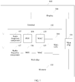
- a terminal 100 in an embodiment of this application includes a main chip 101, a WiFi chip 102, and a memory 103.
- the memory 103 is configured to store a software program.
- An operating system that can be used by the terminal 100 is loaded in the main chip 101.
- the operating system includes at least one body, that is, a main central processing unit (CPU), that uses the WiFi chip 102, and the main CPU is hereinafter briefly referred to as a processor.
- the at least one processor is coupled to the memory 103, and is configured to read the software program from the memory to run the operating system and application software.
- a WiFi CPU that is, a WIFI processor
- 104 is loaded in the WiFi chip 102.
- the WiFi CPU 104 is a WiFi chip kernel processor, and mainly implements a WiFi-related operation function, for example, is responsible for congestion control, carrier aggregation, frame filtering, key control, frame receiving/transmission management, and the like. It may be understood that the main chip 101 and the WiFi chip 102 may be integrated into one chip.
- N WiFi access circuits are integrated into the WiFi chip 102, and N is a natural number greater than or equal to 2.
- Each of the N WiFi access circuits is used for access to one corresponding WiFi network, and each WiFi access circuit corresponds to one independent Media Access Control (MAC) 105 and one independent physical layer (PHY) 106.
- MACs 105 and N PHYs 106 share one WiFi CPU 104, and can receive/transmit data at the same time, so as to implement a dual-band dual-concurrent (DBDC) function.
- Functions of the MAC 105 mainly include channel access, group deframing, data receiving/transmission, encryption/decryption, and energy conservation control. As shown in FIG.
- the MAC 105 may be implemented by using independent hardware such as an independent digital signal processor. Certainly, the MAC 105 may be implemented by using the WiFi CPU 104, that is, functions of the MAC 105 are implemented by using the WiFi CPU 104. FIG. 1 is merely used for reference, and does not impose any limitation.
- the PHY 106 mainly implements a physical layer function such as digital baseband processing.
- the WiFi chip 102 further includes a radio frequency component 107.
- the radio frequency component 107 converts a baseband signal processed by the MAC 105 and the PHY 106 into a radio frequency signal during transmission, and converts a radio frequency signal received from an antenna into a baseband signal during receiving, so that the PHY 106 and the MAC 105 perform further processing.
- WiFi CPU 104 may be replaced with a DSP (digital signal processor) or an independent FPGA (field programmable gate array) chip.
- DSP digital signal processor
- FPGA field programmable gate array
- the at least one processor in the main chip 101 may run the software program to form M containers.
- Each container corresponds to one operating system, the M containers are capable of operating at the same time, each container corresponds to one WiFi network access service, the terminal 100 uses different operating systems when different containers operate, and tasks and data of different WiFi network access services during operation of different containers are mutually isolated, that is, each container has an independent task and independent data, and different containers are corresponding to tasks that do not interfere with each other and data that does not interfere with each other.
- the terminal 100 switches between the operation of different containers.
- the two operating systems may be of different types such as an Android system and a Windows system, or may be of a same type such as dual Android systems.
- Two operating systems of a same type that implement dual-WiFi concurrence may use different kernels, or may use a same kernel, but in the two systems or two containers, data is isolated and user operations are isolated in a specific manner.
- a dual-container intelligent terminal is relatively widely applied.
- One operating system may be corresponding to business application, and the other operating system may be corresponding to personal application.
- the method provided in this application may be applied to a terminal in which at least two containers operate, and optionally, applied to a dual-container terminal.
- the container is software that keeps together an operating system program or an application program and a running component of the operating system program or the application program.
- the container is configured to pack the operating system program or the application program, a library, and another binary file required for running of the operating system program or the application program, so that an independent operating system environment can be provided for the operating system program or the application program.
- each software container may include at least a part of a corresponding operating system.
- each software container may not include an operating system kernel, and in this case, the container may be faster and more flexible than a virtual machine.
- one container may be corresponding to one operating system, and two operating systems may be mutually isolated, so that operations of the two operating systems do not interfere with each other.
- the container mentioned in each embodiment of this application may include one of at least a part of a corresponding operating system (that may selectively include or not include an operating system kernel), a corresponding application program, a corresponding component, corresponding middleware, or a corresponding database, or a combination thereof.
- the container may be configured to implement at least one of a user interface function of a corresponding WiFi network access service, maintenance of an access point start state, or maintenance of a station peer to peer network start state.
- the WiFi CPU 104 is configured to: when a first container in the M containers operates, access a first WiFi network by using a first WiFi access circuit in the N WiFi access circuits, and when the terminal 100 switches from the operation of the first container to operation of a second container in the M containers, access a second WiFi network by using a second WiFi access circuit in the N WiFi access circuits.
- the at least one processor is further configured to: when the WiFi CPU 104 accesses the second WiFi network by using the second WiFi access circuit, continue running the first container in a background running manner, and the WiFi CPU 104 is further configured to continue using the first WiFi access circuit to access the first WiFi network, so as to ensure that a WiFi network connection is not disconnected during switch operation between a foreground operating system and a background operating system.
- the WiFi CPU 104 accesses the first WiFi network according to a preset mapping relationship between containers and WiFi access circuits by using the first WiFi access circuit corresponding to the first container in the N WiFi access circuits; and accesses the second WiFi network according to the mapping relationship by using the second WiFi access circuit corresponding to the second container in the N WiFi access circuits.
- the WiFi CPU 104 when accessing the first WiFi network by using the first WiFi access circuit corresponding to the first container in the N WiFi access circuits, the WiFi CPU 104 performs at least one of channel resource scheduling, Media Access Control, or encryption/decryption related to accessing the first WiFi network; and when accessing the second WiFi network by using the second WiFi access circuit corresponding to the second container in the N WiFi access circuits, the WiFi CPU 104 performs at least one of channel resource scheduling, Media Access Control, or encryption/decryption related to accessing the second WiFi network.
- switch operation between operating systems or corresponding containers is switch operation of the operating systems or the containers between the foreground and the background.
- An operating system or a container is switched from the background to the foreground, and an operating system or a container that originally operates in the foreground is switched to the background.
- Such switch operation does not cause disconnection of a WiFi connection corresponding to an operating system running in the background, and corresponding WiFi data transmission is not disconnected, so as to implement a WiFi dual connectivity and simultaneous data transmission.
- an operating system or a container When an operating system or a container is in a foreground operating state, data or a process of the operating system or the container may be displayed to a user by using a user interface (UI).
- UI user interface
- an operating system or a container is in a background operating state, data or a process of the operating system or the container is not displayed to a user by using a user interface.
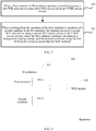
- a procedure of a method for accessing a WiFi network is as follows:
- the terminal when switching to the operation of the second container, uses the second WiFi access circuit to access the second WiFi network.
- the first WiFi access circuit and the second WiFi access circuit are mutually independent, and therefore, the terminal can continue using the first WiFi access circuit in the background to access the first WiFi network, and a service is not disconnected.
- the terminal presets a mapping relationship between containers and WiFi access circuits, accesses the first WiFi network according to the preset mapping relationship between containers and WiFi access circuits by using the first WiFi access circuit corresponding to the first container in the N WiFi access circuits, and accesses the second WiFi network by using the second WiFi access circuit corresponding to the second container in the N WiFi access circuits.
- an embodiment of this application further provides an apparatus 300 for accessing a WiFi network.
- the apparatus 300 includes M containers 301 that are capable of operating at the same time and a WiFi module 302.
- Each container 301 corresponds to one WiFi network access service, tasks and data of different WiFi network access services during operation of different containers 301 are mutually isolated, and the M containers 301 include a first container 301-1 and a second container 301-2.
- the WiFi module 302 is configured to: when the first container 301-1 operates, access a first WiFi network by using a first WiFi access circuit; and is further configured to: when the apparatus 300 switches from the operation of the first container 301-1 to the operation of the second container 301-2, access a second WiFi network by using a second WiFi access circuit.
- the first container 301-1 is further configured to: when the WiFi module 302 accesses the second WiFi network by using the second WiFi access circuit, continue operating in a background running manner, and the WiFi module 302 is further configured to continue using the first WiFi access circuit to access the first WiFi network.
- M and N are natural numbers greater than or equal to 2.
- M is equal to N.
- the WiFi module 302 is configured to access the first WiFi network according to a preset mapping relationship between containers and WiFi access circuits by using the first WiFi access circuit corresponding to the first container 301-1.
- the WiFi module 302 is further configured to access the second WiFi network according to the mapping relationship by using the second WiFi access circuit corresponding to the second container 301-2.
- the WiFi module 302 is further configured to: when accessing the first WiFi network by using the first WiFi access circuit corresponding to the first container 301-1, perform at least one of channel resource scheduling, Media Access Control, or encryption/decryption related to accessing the first WiFi network; and when accessing the second WiFi network by using the second WiFi access circuit corresponding to the second container 301-2, perform at least one of channel resource scheduling, Media Access Control, or encryption/decryption related to accessing the second WiFi network.
- each of the M containers 301 is configured to implement at least one of a user interface function of a corresponding WiFi network access service, maintenance of an access point start state, or maintenance of a station peer to peer network start state.
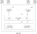
- FIG. 1 For better understanding of the terminal shown in FIG. 1 , the method shown in FIG. 2 , and the apparatus shown in FIG. 3 in the embodiments of this application, the following further describes an implementation of a terminal by using a more detailed schematic diagram of an internal structure stack of a terminal shown in FIG. 4A and FIG. 4B .
- a terminal 400 may use at least two operating systems.
- OSO and OS1 are used for description.
- the following modules are included: a WiFi setting module 401, an AP state machine 402, a station peer to peer (STA P2P) network state machine 403, an interface 404, a network adapter matching module 405, an encryption network access logical entity 406, a WLAN0 407, a P2P0 408, a P2P 409, a scheduling module 410, a WiFi protocol stack 411, and a WiFi access circuit 412.
- the WiFi setting module 401 is a WiFi utilization interface normally used on an intelligent terminal, that is, a user interface software, and is application software run by a main CPU.
- the AP state machine 402 is used for logical implementation of an AP start state in an installation package of the terminal; is software run by the main CPU or a WiFi CPU; is generally run by the main CPU; and is configured to: receive a report from a bottom layer, obtain an access status such as a connected state or a disconnected state or connection signal strength of a WiFi AP, and deliver the obtained access status of the WiFi AP to the WiFi setting module, so that the WiFi setting module 401 displays the access status of the WiFi AP on a user interface.
- the station peer to peer network state machine 403 is used for logical implementation of a STA P2P connection status in the installation package of the terminal.
- the STA P2P state machine is configured to obtain a status of a P2P point, that is, information about a peer device in WiFi direct transmission, is software run by the main CPU or the WiFi CPU, and is generally run by the main CPU.
- the WiFi setting module 401, the AP state machine 402, and the STA P2P state machine 403 that are corresponding to each operating system are included in one container and are run by the main CPU.
- the AP state machine 402 and the STA P2P state machine 403 learn an operating status of a WiFi part (including a WiFi processor and a WiFi access circuit) by maintaining and managing the access status of the WiFi AP and the connection status of the STA P2P, so that a related status is conveniently delivered to the WiFi setting module 401 at an upper layer, and the WiFi setting module 401 can perform corresponding display.
- the interface 404 is an interface logical protocol stack interface layer, and is only an interface for connecting an upper part and a lower part.
- the network adapter matching module 405 is used for network adapter binding and distribution of called network interfaces, that is, used for implementing a correspondence between a high-layer container and a bottom-layer software module such as the encryption network access logical entity 406, the WLAN0 407, the P2P0 408, the P2P 409, the WiFi protocol stack 411, and the WiFi access circuit 412, and is software run by the WiFi CPU.
- the encryption network access logical entity 406 implements a WiFi AP-mode encryption/decryption network access function, and is software run by the WiFi CPU.
- the WLAN0 407 is a WLAN communications entity, is software run by the WiFi CPU, and implements a necessary software function required for WLAN communication.
- the P2P0 408 is a P2P communications entity, is software run by the WiFi CPU, and implements a necessary software function required for P2P communication.
- the P2P 409 is a P2P scanning function, is software run by the WiFi CPU, and implements a necessary software function required for P2P scanning.
- the scheduling module 410 is configured to perform scheduling, including channel resource scheduling and the like, between two virtual access points based on one WiFi CPU.
- the WiFi protocol stack 411 includes at least two independent MACs.
- two MACs are used as an example.
- the MAC may be software run by the WiFi CPU, or certainly, may be implemented by using independent MAC hardware instead of WiFi CPU software.
- WiFi module Software run by the WiFi CPU may be collectively referred to as a WiFi module, may selectively include the interface 404, the network adapter matching module 405, the encryption network access logical entity 406, the scheduling module 410, and the WiFi protocol stack 411, and may further include the WLAN0 407, the P2P0 408, and the P2P 409.
- At least two WiFi access circuits 412 and the WiFi CPU are all included in a WiFi chip, and the at least two WiFi access circuits 412 may include at least two independent PHY layers and at least two radio frequency components.
- the WiFi access circuit 412 may be implemented by using an integrated circuit, that is, the WiFi CPU and the WiFi access circuits including the independent PHY layers and the radio frequency components may be integrated into the WiFi chip.
- the WiFi access circuits and the WiFi CPU form a complete processor, and the processor is integrated into a semiconductor chip by using an integrated circuit technology.
- the WiFi access circuit 412 may be an independent chip, and is implemented in separation from the WiFi CPU. This is not limited in this embodiment.
- the terminal may switch between the two operating systems, OS0 and OS1.
- Each operating system corresponds to operation in one container.
- FIG. 4A and FIG. 4B there are two symmetrical parts. It may be considered that the terminal may operate a virtual device corresponding to each part, that is, may operate a container corresponding to each part.
- a difference between center frequencies of channels used when two containers operate in the terminal needs to be greater than a threshold, for example, needs to be at least 20 MHz.
- the terminal may use a same channel when two containers operates.
- a WLAN and a P2P of the OS0, a WLAN and a P2P of the OS1, an encryption entity of the OS0, and an encryption entity of the OS1 start by default.
- an AP state machine 402 and a STA P2P state machine 403 of the OS0 register with a network adapter matching module 405, and is associated with the corresponding encryption network access logical entity 406 of the OS0, so that a connection to the corresponding encryption network access logical entity 406 is established (certainly, the encryption network access logical entity 406 of the OS1 may be obtained, so that a connection to the corresponding encryption network access logical entity 406 of the OS1 is established).
- a start process of the OS1 is similar to the foregoing start process of the OS0, and details are not described herein again.
- the network adapter matching module 405 needs to store an index of the encryption network access logical entity 406 and indexes of the AP state machine 402 and the STA P2P state machine 403 of the OS0, store a shared variable or a message queue that is used for state machine communication between the encryption network access logical entity 406 and both the AP state machine 402 and the STA P2P state machine 403 of the OS0, and store a connection relationship between each upper-layer state machine of the network adapter matching module 405 and the lower-layer encryption network access logical entity 406.
- Calling a native interface includes calling an interface from the encryption network access logical entity 406 to each state machine and calling an interface from each state machine to the encryption network access logical entity 406, and the network adapter matching module 405 needs to be adaptive to the native interface by using an incremental message mechanism or another process communication mechanism.
- the terminal and the method and apparatus for accessing a WiFi network provided in FIG. 1 to FIG. 4A and FIG. 4B , it can be ensured that a WiFi network connection is not disconnected when a terminal switches between different operating systems, so that WiFi network application is safer, a service is more fluent, and user experience is improved.
- the embodiments of this application provide another method and apparatus for accessing a WiFi network and another terminal, so that one terminal can be connected to two or more different WiFi APs, a WiFi network is not disconnected during switch operation between two WiFi APs, a service is more fluent, and user experience is improved.
- the at least one processor in the main chip 101 may run the software program to form at least two containers.
- the at least one processor in the main chip 101 may run the software program to form only one container, that is, a single-container mode is supported.
- a single container may also be configured to implement at least one of a user interface function of a corresponding WiFi network access service, maintenance of an access point start state, or maintenance of a station peer to peer network start state.
- a terminal mentioned in a method and an apparatus described in FIG. 5 to FIG. 8A and FIG. 8B in the embodiments of this application is for the single-container mode.
- two WiFi network access identifiers may be conveniently displayed on a user interface or a display, so that a user can conveniently learn connection statuses of two WiFi networks, and user experience is improved.
- a container in the terminal 100 supports both a first WiFi network access service and a second WiFi network access service.
- the WiFi CPU 104 is configured to: when an access request for accessing the first WiFi network is received, access the first WiFi network by using a first WiFi access circuit in N WiFi access circuits; and on condition of using the first WiFi access circuit to access the first WiFi network, if an access request for accessing the second WiFi network is received, access the second WiFi network by using a second WiFi access circuit in the N WiFi access circuits.
- the at least one processor included in the main chip 101 is configured to drive a display interface corresponding to the container to synchronously display a first WiFi network access identifier and a second WiFi network access identifier.
- the first WiFi network access identifier represents that the first WiFi network is accessed
- the second WiFi network access identifier represents that the second WiFi network is accessed.
- N is a natural number greater than or equal to 2.
- the terminal 100 may further include a display 108, and the display interface corresponding to the container is displayed on the display 108.
- the at least one processor in the main chip 101 is further configured to drive the display interface to synchronously display connection signal strength of the first WiFi network and connection signal strength of the second WiFi network.
- the WiFi CPU 104 is further configured to: after accessing the first WiFi network and the second WiFi network, select, according to a detected WiFi network connection manner entered by a user, at least one of the first WiFi network or the second WiFi network to carry a data service.
- the WiFi CPU 104 is further configured to perform at least one of channel resource scheduling, Media Access Control, or encryption/decryption related to accessing the first WiFi network and the second WiFi network.
- a procedure of another method for accessing a WiFi network is as follows:
- N is a natural number greater than or equal to 2.
- the terminal After accessing the first WiFi network and the second WiFi network, the terminal synchronously displays a first WiFi network access identifier and a second WiFi network access identifier on a display interface.
- the display interface is shown in FIG. 6 .
- the first WiFi network access identifier represents that the first WiFi network is accessed
- the second WiFi network access identifier represents that the second WiFi network is accessed.
- the terminal may synchronously display connection signal strength of the first WiFi network and connection signal strength of the second WiFi network on the display interface.
- a WiFi network connection manner is pre-configured for the terminal.
- the WiFi network connection manner is used by a user to select a WiFi network to carry a data service.
- the WiFi network connection manner includes: preferably accessing a WiFi AP with a strong signal, or accessing multiple WiFi APs (for example, two WiFi APs) at the same time, or accessing a designated WiFi AP, or the like.
- the terminal selects, according to the detected WiFi network connection manner entered by the user, at least one of the first WiFi network or the second WiFi network to carry the data service.
- the terminal selects, from the first WiFi network and the second WiFi network according to the detected WiFi network connection manner entered by the user, a WiFi network having higher connection signal strength to carry the data service; or selects, according to the detected WiFi network connection manner entered by the user, a WiFi network designated by the user, to carry the data service; or selects, according to the detected WiFi network connection manner entered by the user and according to a load balancing policy, the first WiFi network and the second WiFi network to carry the data service together.
- That the first WiFi network and the second WiFi network are selected according to the load balancing policy to carry the data service together may include but be not limited to the following several cases.
- the terminal uses, according to a traffic balancing policy of the first WiFi network and the second WiFi network, the first WiFi network and the second WiFi network to carry the data service; or the terminal uses, according to a service request quantities balancing policy of the first WiFi network and the second WiFi network, the first WiFi network and the second WiFi network to carry the data service.
- the terminal may further access another network while maintaining the one network access service.
- the two WiFi networks use different WiFi access circuits to operate, and therefore, it can be ensured that the two WiFi networks are online at the same time.
- the foregoing manner may also be referred to as a WiFi dual standby manner.
- an extended case is that more than two WiFi networks are online at the same time. In this way, if the terminal is connected to two WiFi networks at the same time, when a user who holds the terminal moves from one area to another area, it can be ensured that a WiFi network connection is not disconnected, it can be ensured that a service is not disconnected, and user experience can be improved.
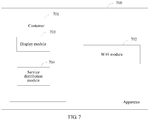
- an embodiment of this application further provides an apparatus 700 for accessing a WiFi network.
- the apparatus 700 includes a container 701 supporting both a first WiFi network access service and a second WiFi network access service and a WiFi module 702.
- the container 701 includes a display module 703.
- the WiFi module 702 is configured to: when an access request for accessing a WiFi network is received, access the first WiFi network by using a first WiFi access circuit in N WiFi access circuits, and is further configured to: on condition of using the first WiFi access circuit to access the first WiFi network, if an access request for accessing the second WiFi network is received, access the second WiFi network by using the second WiFi access circuit.
- N is a natural number greater than or equal to 2.
- the display module 703 is configured to: after the WiFi module accesses the first WiFi network and the second WiFi network, synchronously display a first WiFi network access identifier and a second WiFi network access identifier on a display interface corresponding to the container.
- the first WiFi network access identifier represents that the first WiFi network is accessed
- the second WiFi network access identifier represents that the second WiFi network is accessed.
- the display module 703 is further configured to synchronously display connection signal strength of the first WiFi network and connection signal strength of the second WiFi network on the display interface.
- the apparatus 700 or the container 701 further includes a service distribution module 704.
- the service distribution module 704 may be a part of an operating system, that is, the container 701 includes the service distribution module 704, or certainly, may be a part of software run by a WiFi CPU.
- the service distribution module 704 exists in the container 701.
- the service distribution module 704 is configured to: after the WiFi module accesses the first WiFi network and the second WiFi network, select, according to a detected WiFi network connection manner entered by a user, at least one of the first WiFi network or the second WiFi network to carry a data service.
- the service distribution module 704 is configured to: detect the WiFi network connection manner entered by the user, and select, from the first WiFi network and the second WiFi network according to the detected WiFi network connection manner entered by the user, a WiFi network having higher connection signal strength to carry the data service; or
- the service distribution module 704 uses, according to a traffic balancing policy of the first WiFi network and the second WiFi network, the first WiFi network and the second WiFi network to carry the data service; or uses, according to a service request quantities balancing policy of the first WiFi network and the second WiFi network, the first WiFi network and the second WiFi network to carry the data service.
- the WiFi module 702 is further configured to perform at least one of channel resource scheduling, Media Access Control, or encryption/decryption related to accessing the first WiFi network and the second WiFi network.
- the container 701 is configured to implement at least one of a user interface function of a corresponding WiFi network access service, maintenance of an access point start state, or maintenance of a station peer to peer network start state.
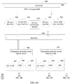
- FIG. 8A and FIG. 8B For better understanding of the method and the apparatus shown in FIG. 5 to FIG. 7 in the embodiments of this application, the following further describes an implementation of a terminal by using a more detailed schematic diagram of an internal structure stack of a terminal shown in FIG. 8A and FIG. 8B .
- a terminal 800 includes a WiFi setting module 801, at least two AP state machines 802 (two AP state machines are used as an example in the figure), at least two STA P2P state machines 803 (two STA P2P state machines are used as an example in the figure), a service distribution module 804, an interface 805, at least two encryption network access logical entities 806 (two encryption network access logical entities are used as an example in the figure), at least two WLANOs 807 (two WLANOs are used as an example in the figure), at least two P2P0s 808 (two P2P0s are used as an example in the figure), at least two P2Ps 809 (two P2Ps are used as an example in the figure), at least two scheduling modules 810, a WiFi protocol stack 811 (two WiFi protocol stacks are used as an example in the figure), and a WiFi access circuit 812.
- the WiFi setting module 801, the at least two AP state machines 802, and the at least two STA P2P state machines 803 may be included in one container, and run by a CPU.
- the service distribution module 804 is also included in the container.
- the service distribution module 804 may be run by a WiFi CPU.
- the WiFi CPU is further configured to run and implement the interface 805, the at least two encryption network access logical entities 806, the at least two WLANOs 807, the at least two P2P0s 808, the at least two P2Ps 809, the at least two scheduling modules 810, and the WiFi protocol stack 811.
- the WiFi CPU and the WiFi access circuit 812 may be integrated into a WiFi chip, or may be implemented separately.
- a module that has a same module name as that of a module in FIG. 4A and FIG. 4B also has a same function as that of the module in FIG. 4A and FIG. 4B , and details are not described herein again.
- the terminal 800 shown in FIG. 8A and FIG. 8B may operate one operating system, that is, may operate in a single-container mode. Therefore, one WiFi setting module 801 is included in FIG. 8A and FIG. 8B , that is, setting is performed by using a setting interface of one operating system. Likewise, it can be learned from FIG. 8A and FIG. 8B that it may be considered that the terminal 800 has two channels that share one CPU.
- One channel may be corresponding to accessing one WiFi network
- the single container of the terminal 800 may use either of the channels, and when using the two channels at the same time according to an appropriate software design, the terminal 800 can be connected to two WiFi networks at the same time, that is, implement a WiFi dual standby function.
- a terminal with more than two channels can implement a WiFi multi-standby function.
- two channels are used as an example, and are not intended to limit the protection scope.
- the service distribution module 804 is configured to execute a function executed by the service distribution module 704 in FIG. 7 .
- the terminal may use different WiFi access circuits for different services in one operating system by using the added service distribution module, so that a concurrent function that multiple WiFi networks are used for multiple services is implemented, and one terminal can be connected to two or more different WiFi APs at the same time, that is, a WiFi dual standby or multi-standby function is implemented.
- a new interface manner is provided, so that at least two WiFi identifiers can be displayed on a display interface of the terminal, and a display manner of WiFi dual standby display or WiFi multi-standby display is implemented.
- this application may be provided as a method, a system, or a computer program product. Therefore, a part of content in the method designed in this application may be implemented by using software, or in a form of embodiments with a combination of software and hardware. Moreover, this application may use a form of a computer program product that is implemented on one or more computer-usable storage media (including but not limited to a disk memory, a CD-ROM, an optical memory, and the like) that include computer usable program code.
- a software-driven program such as an operating system program, or container software, or necessary software required by a WiFi CPU, that is executed by a main CPU or the WiFi CPU may be stored in the storage media, and executed by a corresponding processor.
- These computer program instructions may be provided for a general-purpose computer, a dedicated computer, an embedded processor, or a processor of any other programmable data processing device to generate a machine, so that the instructions executed by a computer or a processor of any other programmable data processing device generate an apparatus for implementing a specific function in one or more processes in the flowcharts and/or in one or more blocks in the block diagrams.
- These computer program instructions may be stored in a computer readable memory that can instruct the computer or any other programmable data processing device to work in a specific manner, so that the instructions stored in the computer readable memory generate an artifact that includes an instruction apparatus.
- the instruction apparatus implements a specific function in one or more processes in the flowcharts and/or in one or more blocks in the block diagrams.
- These computer program instructions may be loaded onto a computer or another programmable data processing device, so that a series of operations and steps are performed on the computer or the another programmable device, thereby generating computer-implemented processing. Therefore, the instructions executed on the computer or the another programmable device provide steps for implementing a specific function in one or more processes in the flowcharts and/or in one or more blocks in the block diagrams.
Landscapes
- Engineering & Computer Science (AREA)
- Computer Networks & Wireless Communication (AREA)
- Signal Processing (AREA)
- Computer Security & Cryptography (AREA)
- Mobile Radio Communication Systems (AREA)
- Telephone Function (AREA)
- Telephonic Communication Services (AREA)
Claims (10)
- Procédé d'accès à un réseau WiFi selon la norme IEEE 802.11, le procédé étant appliqué à un terminal (100), le terminal (100) comprenant N circuits d'accès WiFi et au moins un processeur, l'au moins un processeur étant configuré pour exécuter un programme logiciel pour former M conteneurs (301), chaque conteneur correspondant à un service d'accès au réseau WiFi, les M conteneurs (301) étant exploitables en même temps, les tâches et données de différents services d'accès au réseau WiFi lors de l'exploitation de différents conteneurs étant mutuellement isolées, chaque conteneur correspondant à un système d'exploitation correspondant et comprenant au moins une partie de celui-ci, et le procédé comprenant :l'accès (200), par le terminal (100), à un premier réseau WiFi au moyen d'un premier circuit d'accès WiFi des N circuits d'accès WiFi lorsqu'un premier conteneur (301-1) des M conteneurs (301) est en exploitation ; etl'accès (201), par le terminal (100), à un second réseau WiFi au moyen d'un deuxième circuit d'accès WiFi des N circuits d'accès WiFi lorsque le terminal (100) passe de l'exploitation du premier conteneur (301-1) à l'exploitation d'un deuxième conteneur (301-2) des M conteneurs (301),le premier conteneur (301-1) continuant d'être en exploitation par exécution en arrière-plan, et le terminal (100) continuant d'utiliser le premier circuit d'accès WiFi pour accéder au premier réseau WiFi,M et N étant des entiers naturels supérieurs ou égaux à 2 ;le terminal (100) comprenant en outre un processeur WiFi ;l'accès (200), par le terminal (100), à un premier réseau WiFi au moyen d'un premier circuit d'accès WiFi des N circuits d'accès WiFi lorsqu'un premier conteneur (301-1) est en exploitation comprenant :l'accès, par le processeur WiFi du terminal (100), au premier réseau WiFi selon une relation de mappage prédéfinie entre les conteneurs et les circuits d'accès WiFi au moyen du premier circuit d'accès WiFi correspondant au premier conteneur (301-1) des N circuits d'accès WiFi ; etl'accès (201), par le terminal (100), à un second réseau WiFi au moyen d'un deuxième circuit d'accès WiFi des N circuits d'accès WiFi lorsque le terminal (100) passe à l'exploitation du deuxième conteneur (301-2) comprenant :
l'accès, par le processeur WiFi du terminal (100), au second réseau WiFi selon la relation de mappage au moyen du deuxième circuit d'accès WiFi correspondant au deuxième conteneur (301-2) des N circuits d'accès WiFi. - Procédé selon la revendication 1, lorsque l'accès au premier réseau WiFi se fait au moyen du premier circuit d'accès WiFi correspondant au premier conteneur (301-1) des N circuits d'accès WiFi, le procédé comprenant en outre : la réalisation, par le processeur WiFi du terminal (100), de la planification des ressources de canal et/ou de la commande d'accès au support et/ou du chiffrement/déchiffrement lié à l'accès au premier réseau WiFi ; et
lorsque l'accès au second réseau WiFi se fait au moyen du deuxième circuit d'accès WiFi correspondant au deuxième conteneur (301-2) des N circuits d'accès WiFi, le procédé comprenant en outre : la réalisation, par le processeur WiFi du terminal (100), de la planification des ressources de canal et/ou de la commande d'accès au support et/ou du chiffrement/déchiffrement lié à l'accès au second réseau WiFi. - Procédé selon la revendication 1 ou 2, chaque conteneur étant configuré pour mettre en œuvre une fonction d'interface utilisateur d'un service d'accès au réseau WiFi correspondant et/ou une maintenance d'un état de démarrage d'un point d'accès et/ou une maintenance d'un état de démarrage de station de réseau pair à pair.
- Procédé selon l'une quelconque des revendications 1 à 3, M et N étant tous deux égaux à 2.
- Appareil d'accès à un réseau WiFi selon la norme IEEE 802.11, l'appareil comprenant M conteneurs (301) qui sont exploitables en même temps et un module WiFi (302) qui est un logiciel exécuté par une CPU WiFi, chaque conteneur correspondant à un service d'accès au réseau WiFi, les tâches et données de différents services d'accès au réseau WiFi lors de l'exploitation de différents conteneurs étant mutuellement isolées, chaque conteneur correspondant à un système d'exploitation correspondant et comprenant au moins une partie de celui-ci, et les M conteneurs (301) comprenant un premier conteneur (301-1) et un deuxième conteneur (301-2) ;le module WiFi (302) étant configuré pour : lorsque le premier conteneur (301-1) est en exploitation, accéder à un premier réseau WiFi au moyen d'un premier circuit d'accès WiFi, et étant en outre configuré pour : lorsque l'appareil passe de l'exploitation du premier conteneur (301-1) à l'exploitation du deuxième conteneur (301-2), accéder à un second réseau WiFi au moyen d'un deuxième circuit d'accès WiFi ; etle premier conteneur (301-1) étant en outre configuré pour : lorsque le module WiFi (302) accède au second réseau WiFi au moyen du deuxième circuit d'accès WiFi, continuer à être exploité par exécution en arrière-plan, et le module WiFi (302) étant en outre configuré pour continuer à utiliser le premier circuit d'accès WiFi pour accéder au premier réseau WiFi,M étant un entier naturel supérieur ou égal à 2 ;le module WiFi (302) étant configuré pour : accéder au premier réseau WiFi selon une relation de mappage prédéfinie entre les conteneurs et les circuits d'accès WiFi au moyen du premier circuit d'accès WiFi correspondant au premier conteneur (301-1), et accéder au second réseau WiFi selon la relation de mappage au moyen du deuxième circuit d'accès WiFi correspondant au deuxième conteneur (301-2).
- Appareil selon la revendication 5, le module WiFi (302) étant en outre configuré pour :lors de l'accès au premier réseau WiFi au moyen du premier circuit d'accès WiFi correspondant au premier conteneur (301-1), réaliser la planification des ressources de canal et/ou la commande d'accès au support et/ou le chiffrement/déchiffrement lié à l'accès au premier réseau WiFi ; etlors de l'accès au second réseau WiFi au moyen du deuxième circuit d'accès WiFi correspondant au deuxième conteneur (301-2), réaliser la planification des ressources de canal et/ou la commande d'accès au support et/ou le chiffrement/déchiffrement lié à l'accès au second réseau WiFi.
- Appareil selon la revendication 5 ou 6, chaque conteneur étant configuré pour mettre en œuvre une fonction d'interface utilisateur d'un service d'accès au réseau WiFi correspondant et/ou une maintenance d'un état de démarrage d'un point d'accès et/ou une maintenance d'un état de démarrage de station de réseau pair à pair.
- Appareil selon l'une quelconque des revendications 5 à 7, M étant égal à 2.
- Support de stockage lisible par ordinateur stockant des instructions de programme informatique qui, lorsqu'elles sont exécutées sur un ordinateur ou sur un autre dispositif programmable, effectuent le procédé selon l'une quelconque des revendications 1 à 4.
- Programme informatique comprenant des instructions de programme informatique qui, lorsqu'elles sont exécutées sur un ordinateur ou sur un autre dispositif programmable, effectuent le procédé selon l'une quelconque des revendications 1 à 4.
Priority Applications (1)
| Application Number | Priority Date | Filing Date | Title |
|---|---|---|---|
| EP21168002.0A EP3920657A1 (fr) | 2016-05-27 | 2016-11-14 | Procédé et appareil d'accès à un réseau wifi |
Applications Claiming Priority (2)
| Application Number | Priority Date | Filing Date | Title |
|---|---|---|---|
| CN201610370643.4A CN106102098B (zh) | 2016-05-27 | 2016-05-27 | 一种接入wifi网络的方法及装置 |
| PCT/CN2016/105777 WO2017201983A1 (fr) | 2016-05-27 | 2016-11-14 | Procédé et appareil d'accès à un réseau wifi |
Related Child Applications (2)
| Application Number | Title | Priority Date | Filing Date |
|---|---|---|---|
| EP21168002.0A Division EP3920657A1 (fr) | 2016-05-27 | 2016-11-14 | Procédé et appareil d'accès à un réseau wifi |
| EP21168002.0A Division-Into EP3920657A1 (fr) | 2016-05-27 | 2016-11-14 | Procédé et appareil d'accès à un réseau wifi |
Publications (3)
| Publication Number | Publication Date |
|---|---|
| EP3439357A1 EP3439357A1 (fr) | 2019-02-06 |
| EP3439357A4 EP3439357A4 (fr) | 2019-05-01 |
| EP3439357B1 true EP3439357B1 (fr) | 2021-09-22 |
Family
ID=57229500
Family Applications (2)
| Application Number | Title | Priority Date | Filing Date |
|---|---|---|---|
| EP21168002.0A Pending EP3920657A1 (fr) | 2016-05-27 | 2016-11-14 | Procédé et appareil d'accès à un réseau wifi |
| EP16902967.5A Active EP3439357B1 (fr) | 2016-05-27 | 2016-11-14 | Procédé et appareil d'accès à un réseau wifi |
Family Applications Before (1)
| Application Number | Title | Priority Date | Filing Date |
|---|---|---|---|
| EP21168002.0A Pending EP3920657A1 (fr) | 2016-05-27 | 2016-11-14 | Procédé et appareil d'accès à un réseau wifi |
Country Status (6)
| Country | Link |
|---|---|
| US (2) | US10849053B2 (fr) |
| EP (2) | EP3920657A1 (fr) |
| JP (1) | JP6766993B2 (fr) |
| KR (1) | KR102147233B1 (fr) |
| CN (3) | CN106102098B (fr) |
| WO (1) | WO2017201983A1 (fr) |
Families Citing this family (34)
| Publication number | Priority date | Publication date | Assignee | Title |
|---|---|---|---|---|
| CN106102098B (zh) | 2016-05-27 | 2019-09-13 | 华为技术有限公司 | 一种接入wifi网络的方法及装置 |
| CN108089928B (zh) * | 2016-11-22 | 2022-01-14 | 华为技术有限公司 | 终端控制方法及装置 |
| WO2018153427A1 (fr) * | 2017-02-21 | 2018-08-30 | Telefonaktiebolaget Lm Ericsson (Publ) | Procédé et dispositifs pour une double connectivité entre un équipement d'utilisateur à double pile de protocoles et deux unités de bande de base d'un réseau d'accès radio dans un réseau de télécommunications |
| CN107148060A (zh) * | 2017-05-23 | 2017-09-08 | 维沃移动通信有限公司 | 一种网络连接方法及其应用的移动终端 |
| US20190012184A1 (en) * | 2017-07-04 | 2019-01-10 | Cloudendure Ltd. | System and method for deploying cloud based computing environment agnostic applications |
| CN107635234B (zh) * | 2017-09-29 | 2021-07-23 | 努比亚技术有限公司 | Wi-Fi控制方法、移动终端及计算机可读存储介质 |
| CN108390810B (zh) * | 2018-01-05 | 2021-07-30 | 郑州信大捷安信息技术股份有限公司 | 一种基于单Linux内核多Android系统网络虚拟化方法 |
| US11194935B2 (en) * | 2018-03-07 | 2021-12-07 | Iurii V. Iuzifovich | Method of securing devices used in the internet of things |
| CN111919505B (zh) * | 2018-03-26 | 2022-10-18 | 华为技术有限公司 | 数据处理方法以及终端 |
| CN109257783A (zh) * | 2018-11-09 | 2019-01-22 | 浙江国自机器人技术有限公司 | 一种漫游切换方法、装置、系统及可读存储介质 |
| CN109743712A (zh) * | 2018-12-29 | 2019-05-10 | Oppo广东移动通信有限公司 | 数据传输控制方法及相关产品 |
| CN109673001A (zh) * | 2019-02-12 | 2019-04-23 | Oppo广东移动通信有限公司 | 数据传输控制方法及相关产品 |
| CN109803318B (zh) * | 2019-02-12 | 2021-01-22 | Oppo广东移动通信有限公司 | 数据包分流方法、装置、移动终端及存储介质 |
| CN109803325B (zh) * | 2019-02-12 | 2020-12-22 | Oppo广东移动通信有限公司 | 数据分流方法、装置、移动终端及存储介质 |
| CN110475315B (zh) * | 2019-08-19 | 2021-05-14 | Oppo广东移动通信有限公司 | 网络连接控制方法及相关产品 |
| CN112449401B (zh) * | 2019-08-31 | 2022-03-08 | Oppo广东移动通信有限公司 | WiFi漫游方法、装置、移动终端及存储介质 |
| CN110572829B (zh) * | 2019-09-05 | 2022-08-16 | Oppo(重庆)智能科技有限公司 | 网络连接控制方法及相关产品 |
| CN110569099B (zh) * | 2019-09-17 | 2021-07-06 | Oppo广东移动通信有限公司 | 消息显示方法及相关产品 |
| CN110769524A (zh) * | 2019-09-26 | 2020-02-07 | 维沃移动通信有限公司 | 一种多网络接入方法及终端设备 |
| CN110730517B (zh) * | 2019-10-22 | 2021-06-29 | Oppo广东移动通信有限公司 | 网络连接控制方法及相关产品 |
| CN113056037B (zh) * | 2019-12-27 | 2023-04-28 | 华为技术有限公司 | 网络标识的显示方法、设备及系统 |
| CN111148278A (zh) * | 2019-12-30 | 2020-05-12 | Oppo广东移动通信有限公司 | 数据传输方法、装置、存储介质及电子设备 |
| CN114025410A (zh) * | 2020-01-08 | 2022-02-08 | 华为技术有限公司 | 建立网络连接的方法和装置以及电子设备 |
| WO2022046090A1 (fr) * | 2020-08-31 | 2022-03-03 | Hewlett-Packard Development Company, L.P. | Dispositifs informatiques dotés de doubles émetteurs-récepteurs wi-fi |
| CN114244804B (zh) * | 2020-09-08 | 2023-03-21 | 成都鼎桥通信技术有限公司 | 基于双系统的网络器件启动方法、设备及存储介质 |
| CN112333800A (zh) * | 2020-11-13 | 2021-02-05 | Oppo广东移动通信有限公司 | 网络切换方法、装置、存储介质及电子设备 |
| CN112804704B (zh) * | 2020-12-18 | 2022-08-19 | 珠海格力电器股份有限公司 | 一种wifi模块自动测试设备及测试方法 |
| CN112752284B (zh) * | 2020-12-30 | 2022-11-04 | 惠州Tcl移动通信有限公司 | 双wifi下的应用网络优化方法、装置、设备及介质 |
| CN114867035A (zh) * | 2021-02-04 | 2022-08-05 | 华为技术有限公司 | WiFi扫描控制方法和相关装置 |
| CN113784393B (zh) * | 2021-05-14 | 2023-04-07 | 荣耀终端有限公司 | 一种峰值下载方法和装置 |
| CN113596919B (zh) * | 2021-06-16 | 2022-12-20 | 荣耀终端有限公司 | 数据下载方法、装置和终端设备 |
| CN113490291B (zh) * | 2021-06-16 | 2022-05-17 | 荣耀终端有限公司 | 数据下载方法、装置和终端设备 |
| US20230089923A1 (en) * | 2021-09-22 | 2023-03-23 | Qualcomm Incorporated | Physical uplink channel handling based on channel security |
| CN116133161B (zh) * | 2023-04-14 | 2023-08-22 | 荣耀终端有限公司 | 数据传输方法及电子设备 |
Family Cites Families (38)
| Publication number | Priority date | Publication date | Assignee | Title |
|---|---|---|---|---|
| JPH0737383Y2 (ja) * | 1990-03-13 | 1995-08-23 | 株式会社ケンウッド | 複数波同時表示のシグナルメータ |
| KR100547729B1 (ko) * | 1998-07-02 | 2006-04-20 | 삼성전자주식회사 | 휴대 전화 단말 장치의 전계 강도 디스플레이 방법 |
| US7409674B2 (en) * | 2002-12-26 | 2008-08-05 | Research In Motion Limited | System and method of creating and communicating with component based wireless applications |
| US9003048B2 (en) | 2003-04-01 | 2015-04-07 | Microsoft Technology Licensing, Llc | Network zones |
| US20040196812A1 (en) * | 2003-04-07 | 2004-10-07 | Instant802 Networks Inc. | Multi-band access point with shared processor |
| JP2007116509A (ja) * | 2005-10-21 | 2007-05-10 | Nec Corp | 通信端末、プログラム、通信システム及びセキュリティ情報出力方法 |
| US9549434B2 (en) * | 2006-03-09 | 2017-01-17 | Qualcomm Incorporated | System and method for multi-network coverage |
| US7761119B2 (en) * | 2006-07-05 | 2010-07-20 | Kyocera Corporation | Signal strength annunciators for multi-mode wireless communication devices |
| US8605662B2 (en) * | 2007-07-20 | 2013-12-10 | Cisco Technology, Inc. | Intelligent real access point name (APN) selection using virtual APNS |
| US8744451B2 (en) * | 2007-12-12 | 2014-06-03 | Aruba Networks, Inc. | Delayed ACK in dual-mode call handover |
| US8249649B2 (en) | 2010-07-02 | 2012-08-21 | Google Inc. | Mobile device configured to operate on multiple different networks |
| KR101931194B1 (ko) | 2011-01-06 | 2018-12-21 | 알테어 세미콘덕터 엘티디. | Lte wifi 공존 |
| US8761147B2 (en) * | 2011-01-17 | 2014-06-24 | Texas Instruments Incorporated | Selective protection based on sequence numbers in coexisting networks |
| KR20130004964A (ko) * | 2011-07-05 | 2013-01-15 | 주식회사 엘지유플러스 | 무선 인터넷용 듀얼 와이파이 장치 및 그 장치를 이용한 무선 인터넷 시스템 |
| CN202602915U (zh) * | 2012-05-14 | 2012-12-12 | 成都飞鱼星科技开发有限公司 | 一种无线路由器 |
| JP6408753B2 (ja) | 2012-05-17 | 2018-10-17 | キヤノン株式会社 | 通信装置、通信装置の制御方法、プログラム |
| CN202873086U (zh) * | 2012-10-31 | 2013-04-10 | 上海斐讯数据通信技术有限公司 | 无线双频ap |
| CN103001702B (zh) * | 2012-12-31 | 2015-07-29 | 深圳东志科技有限公司 | 一种双WiFi光网络单元 |
| US20150220243A1 (en) | 2013-05-10 | 2015-08-06 | Jinrong Yang | Spatially-enhanced accessibility aid for a display device |
| US9923581B2 (en) * | 2013-10-14 | 2018-03-20 | Netgear, Inc. | Front-end module and antenna design for a wireless device simultaneously using WLAN modules operating in different wireless bands |
| CN103561172B (zh) * | 2013-10-31 | 2015-03-04 | 福州瑞芯微电子有限公司 | 一种Android系统上支持多WIFI模块的方法及系统 |
| US9842499B2 (en) * | 2013-12-09 | 2017-12-12 | Lg Electronics Inc. | Device enabling exchange of abnormal signal among vehicles via Wi-Fi direct network, and control method therefor |
| JP6100713B2 (ja) * | 2014-02-25 | 2017-03-22 | Necプラットフォームズ株式会社 | 通信装置および通信システム |
| JP6311417B2 (ja) * | 2014-04-08 | 2018-04-18 | 富士通株式会社 | 無線通信装置、無線通信方法および無線通信プログラム |
| CN105592504B (zh) * | 2014-10-23 | 2019-03-08 | 东莞宇龙通信科技有限公司 | 多wifi模块的传输方法、传输装置和终端 |
| US9832808B2 (en) * | 2014-12-02 | 2017-11-28 | Cisco Technology, Inc. | Method to provide dual connectivity using LTE master eNodeB and Wi-Fi based secondary eNodeB |
| US9268561B1 (en) * | 2014-12-10 | 2016-02-23 | Sap Se | Federated services to dynamically switch features in applications |
| CN104516760B (zh) * | 2014-12-12 | 2018-01-09 | 华为技术有限公司 | 一种操作系统热切换的方法、装置及移动终端 |
| CN105046156B (zh) * | 2015-08-26 | 2018-05-08 | 北京元心科技有限公司 | 智能终端及其设备访问权限控制方法 |
| US9681301B2 (en) * | 2015-09-25 | 2017-06-13 | Mutualink, Inc. | Enabling emergency access to secure wireless communications networks |
| CN105227782A (zh) * | 2015-10-30 | 2016-01-06 | 维沃移动通信有限公司 | 一种移动终端操作系统的切换方法和移动终端 |
| KR102447179B1 (ko) * | 2015-11-19 | 2022-09-26 | 삼성전자 주식회사 | 무선 통신 방법 및 이를 제공하는 전자 장치 |
| CN205210862U (zh) * | 2015-11-23 | 2016-05-04 | 安徽兰酷电子科技有限公司 | 一种可远程访问的双连接无线存储装置 |
| US10499260B2 (en) * | 2016-01-08 | 2019-12-03 | Microsoft Technology Licensing, Llc | Adaptive profiles with SDR |
| CN105516397B (zh) * | 2016-01-19 | 2019-06-11 | 深圳前海达闼云端智能科技有限公司 | 多操作系统终端接入网络的方法及多操作系统终端 |
| CN106102098B (zh) * | 2016-05-27 | 2019-09-13 | 华为技术有限公司 | 一种接入wifi网络的方法及装置 |
| WO2018182604A1 (fr) * | 2017-03-30 | 2018-10-04 | Intel Corporation | Virtualisation par passage d'accès protégé wifi 2 (wpa2) |
| US10708968B2 (en) * | 2017-08-25 | 2020-07-07 | Kt Corporation | Method of controlling mobility of UE and apparatus therefor |
-
2016
- 2016-05-27 CN CN201610370643.4A patent/CN106102098B/zh active Active
- 2016-05-27 CN CN201910849768.9A patent/CN110602806B/zh active Active
- 2016-05-27 CN CN201910849778.2A patent/CN110545281B/zh active Active
- 2016-11-14 EP EP21168002.0A patent/EP3920657A1/fr active Pending
- 2016-11-14 JP JP2018557032A patent/JP6766993B2/ja active Active
- 2016-11-14 EP EP16902967.5A patent/EP3439357B1/fr active Active
- 2016-11-14 WO PCT/CN2016/105777 patent/WO2017201983A1/fr active Application Filing
- 2016-11-14 KR KR1020187033219A patent/KR102147233B1/ko active IP Right Grant
-
2018
- 2018-11-27 US US16/201,563 patent/US10849053B2/en active Active
-
2020
- 2020-06-16 US US16/903,262 patent/US11330510B2/en active Active
Also Published As
| Publication number | Publication date |
|---|---|
| WO2017201983A1 (fr) | 2017-11-30 |
| CN110602806B (zh) | 2021-04-09 |
| EP3439357A4 (fr) | 2019-05-01 |
| CN110545281A (zh) | 2019-12-06 |
| US11330510B2 (en) | 2022-05-10 |
| CN106102098B (zh) | 2019-09-13 |
| KR20180132892A (ko) | 2018-12-12 |
| JP6766993B2 (ja) | 2020-10-14 |
| EP3920657A1 (fr) | 2021-12-08 |
| EP3439357A1 (fr) | 2019-02-06 |
| KR102147233B1 (ko) | 2020-08-24 |
| US10849053B2 (en) | 2020-11-24 |
| CN106102098A (zh) | 2016-11-09 |
| JP2019520726A (ja) | 2019-07-18 |
| CN110602806A (zh) | 2019-12-20 |
| US20190098566A1 (en) | 2019-03-28 |
| US20200314739A1 (en) | 2020-10-01 |
| CN110545281B (zh) | 2022-01-18 |
Similar Documents
| Publication | Publication Date | Title |
|---|---|---|
| EP3439357B1 (fr) | Procédé et appareil d'accès à un réseau wifi | |
| EP3322217B1 (fr) | Procédé de commutation de point d'accès sans fil, terminal mobile et support de stockage | |
| US20180278289A1 (en) | Mobile terminal and wireless communication method | |
| CN102355707B (zh) | 支持长期演进中的机器类型通信应用的装置和方法 | |
| CN109561485A (zh) | 一种通信方法、接入网设备、核心网设备和用户设备 | |
| WO2013170529A1 (fr) | Terminal multi-mode et procédé de mise en œuvre de service pour terminal multi-mode | |
| CN109151950B (zh) | 一种接入控制的方法、网络设备以及终端设备 | |
| EP3462780B1 (fr) | Procédé et dispositif de traitement de bande de fréquence | |
| GB2507490A (en) | Handling of device-to-device data units during handover to a cellular bearer | |
| CN114557124A (zh) | 通信方法、设备及系统 | |
| CN102083177A (zh) | 通信实现方法和终端 | |
| US11889582B2 (en) | Terminal device to determine whether to re-establish a PDCP layer entity based on indication received from a network device | |
| EP3753295A1 (fr) | Procédé de transfert de technologie d'accès inter-radio | |
| CN107222937B (zh) | 一种数据传输方法、装置及终端 | |
| CN113747605A (zh) | 通信方法和通信装置 | |
| CN117279120A (zh) | 分离式多链路系统 | |
| US11477719B1 (en) | Wireless communication service responsive to an artificial intelligence (AI) network | |
| EP4278809A1 (fr) | Accès aléatoire comprenant l'envoi ou la réception d'un message msg3 | |
| CN110958603A (zh) | 能力上报方法及装置 | |
| EP4068672A1 (fr) | Classes de bande passante d'agrégation de support avec plages de bande passante se chevauchant | |
| WO2020200038A1 (fr) | Procédé et dispositif de commande d'admission | |
| US20230309191A1 (en) | Emergency call method and apparatus, storage medium, and terminal | |
| CN114731507A (zh) | 通信方法、设备及系统 | |
| CN117580149A (zh) | 辅小区添加方法、装置、终端、网络设备及介质 | |
| CN116134889A (zh) | 一种参数指示方法及通信装置 |
Legal Events
| Date | Code | Title | Description |
|---|---|---|---|
| STAA | Information on the status of an ep patent application or granted ep patent |
Free format text: STATUS: THE INTERNATIONAL PUBLICATION HAS BEEN MADE |
|
| PUAI | Public reference made under article 153(3) epc to a published international application that has entered the european phase |
Free format text: ORIGINAL CODE: 0009012 |
|
| STAA | Information on the status of an ep patent application or granted ep patent |
Free format text: STATUS: REQUEST FOR EXAMINATION WAS MADE |
|
| 17P | Request for examination filed |
Effective date: 20181031 |
|
| AK | Designated contracting states |
Kind code of ref document: A1 Designated state(s): AL AT BE BG CH CY CZ DE DK EE ES FI FR GB GR HR HU IE IS IT LI LT LU LV MC MK MT NL NO PL PT RO RS SE SI SK SM TR |
|
| AX | Request for extension of the european patent |
Extension state: BA ME |
|
| RIC1 | Information provided on ipc code assigned before grant |
Ipc: H04W 28/08 20090101AFI20190314BHEP Ipc: H04L 29/06 20060101ALI20190314BHEP Ipc: H04W 88/06 20090101ALI20190314BHEP |
|
| A4 | Supplementary search report drawn up and despatched |
Effective date: 20190328 |
|
| DAV | Request for validation of the european patent (deleted) | ||
| DAX | Request for extension of the european patent (deleted) | ||
| STAA | Information on the status of an ep patent application or granted ep patent |
Free format text: STATUS: EXAMINATION IS IN PROGRESS |
|
| 17Q | First examination report despatched |
Effective date: 20200224 |
|
| STAA | Information on the status of an ep patent application or granted ep patent |
Free format text: STATUS: EXAMINATION IS IN PROGRESS |
|
| GRAP | Despatch of communication of intention to grant a patent |
Free format text: ORIGINAL CODE: EPIDOSNIGR1 |
|
| STAA | Information on the status of an ep patent application or granted ep patent |
Free format text: STATUS: GRANT OF PATENT IS INTENDED |
|
| INTG | Intention to grant announced |
Effective date: 20210510 |
|
| GRAS | Grant fee paid |
Free format text: ORIGINAL CODE: EPIDOSNIGR3 |
|
| GRAA | (expected) grant |
Free format text: ORIGINAL CODE: 0009210 |
|
| STAA | Information on the status of an ep patent application or granted ep patent |
Free format text: STATUS: THE PATENT HAS BEEN GRANTED |
|
| AK | Designated contracting states |
Kind code of ref document: B1 Designated state(s): AL AT BE BG CH CY CZ DE DK EE ES FI FR GB GR HR HU IE IS IT LI LT LU LV MC MK MT NL NO PL PT RO RS SE SI SK SM TR |
|
| REG | Reference to a national code |
Ref country code: GB Ref legal event code: FG4D |
|
| REG | Reference to a national code |
Ref country code: DE Ref legal event code: R096 Ref document number: 602016064171 Country of ref document: DE |
|
| REG | Reference to a national code |
Ref country code: IE Ref legal event code: FG4D |
|
| REG | Reference to a national code |
Ref country code: CH Ref legal event code: EP Ref country code: AT Ref legal event code: REF Ref document number: 1433319 Country of ref document: AT Kind code of ref document: T Effective date: 20211015 |
|
| REG | Reference to a national code |
Ref country code: LT Ref legal event code: MG9D |
|
| REG | Reference to a national code |
Ref country code: NL Ref legal event code: MP Effective date: 20210922 |
|
| PG25 | Lapsed in a contracting state [announced via postgrant information from national office to epo] |
Ref country code: NO Free format text: LAPSE BECAUSE OF FAILURE TO SUBMIT A TRANSLATION OF THE DESCRIPTION OR TO PAY THE FEE WITHIN THE PRESCRIBED TIME-LIMIT Effective date: 20211222 Ref country code: HR Free format text: LAPSE BECAUSE OF FAILURE TO SUBMIT A TRANSLATION OF THE DESCRIPTION OR TO PAY THE FEE WITHIN THE PRESCRIBED TIME-LIMIT Effective date: 20210922 Ref country code: FI Free format text: LAPSE BECAUSE OF FAILURE TO SUBMIT A TRANSLATION OF THE DESCRIPTION OR TO PAY THE FEE WITHIN THE PRESCRIBED TIME-LIMIT Effective date: 20210922 Ref country code: LT Free format text: LAPSE BECAUSE OF FAILURE TO SUBMIT A TRANSLATION OF THE DESCRIPTION OR TO PAY THE FEE WITHIN THE PRESCRIBED TIME-LIMIT Effective date: 20210922 Ref country code: BG Free format text: LAPSE BECAUSE OF FAILURE TO SUBMIT A TRANSLATION OF THE DESCRIPTION OR TO PAY THE FEE WITHIN THE PRESCRIBED TIME-LIMIT Effective date: 20211222 Ref country code: RS Free format text: LAPSE BECAUSE OF FAILURE TO SUBMIT A TRANSLATION OF THE DESCRIPTION OR TO PAY THE FEE WITHIN THE PRESCRIBED TIME-LIMIT Effective date: 20210922 Ref country code: SE Free format text: LAPSE BECAUSE OF FAILURE TO SUBMIT A TRANSLATION OF THE DESCRIPTION OR TO PAY THE FEE WITHIN THE PRESCRIBED TIME-LIMIT Effective date: 20210922 |
|
| REG | Reference to a national code |
Ref country code: AT Ref legal event code: MK05 Ref document number: 1433319 Country of ref document: AT Kind code of ref document: T Effective date: 20210922 |
|
| PG25 | Lapsed in a contracting state [announced via postgrant information from national office to epo] |
Ref country code: LV Free format text: LAPSE BECAUSE OF FAILURE TO SUBMIT A TRANSLATION OF THE DESCRIPTION OR TO PAY THE FEE WITHIN THE PRESCRIBED TIME-LIMIT Effective date: 20210922 Ref country code: GR Free format text: LAPSE BECAUSE OF FAILURE TO SUBMIT A TRANSLATION OF THE DESCRIPTION OR TO PAY THE FEE WITHIN THE PRESCRIBED TIME-LIMIT Effective date: 20211223 |
|
| PG25 | Lapsed in a contracting state [announced via postgrant information from national office to epo] |
Ref country code: AT Free format text: LAPSE BECAUSE OF FAILURE TO SUBMIT A TRANSLATION OF THE DESCRIPTION OR TO PAY THE FEE WITHIN THE PRESCRIBED TIME-LIMIT Effective date: 20210922 |
|
| PG25 | Lapsed in a contracting state [announced via postgrant information from national office to epo] |
Ref country code: IS Free format text: LAPSE BECAUSE OF FAILURE TO SUBMIT A TRANSLATION OF THE DESCRIPTION OR TO PAY THE FEE WITHIN THE PRESCRIBED TIME-LIMIT Effective date: 20220122 Ref country code: SK Free format text: LAPSE BECAUSE OF FAILURE TO SUBMIT A TRANSLATION OF THE DESCRIPTION OR TO PAY THE FEE WITHIN THE PRESCRIBED TIME-LIMIT Effective date: 20210922 Ref country code: RO Free format text: LAPSE BECAUSE OF FAILURE TO SUBMIT A TRANSLATION OF THE DESCRIPTION OR TO PAY THE FEE WITHIN THE PRESCRIBED TIME-LIMIT Effective date: 20210922 Ref country code: PT Free format text: LAPSE BECAUSE OF FAILURE TO SUBMIT A TRANSLATION OF THE DESCRIPTION OR TO PAY THE FEE WITHIN THE PRESCRIBED TIME-LIMIT Effective date: 20220124 Ref country code: PL Free format text: LAPSE BECAUSE OF FAILURE TO SUBMIT A TRANSLATION OF THE DESCRIPTION OR TO PAY THE FEE WITHIN THE PRESCRIBED TIME-LIMIT Effective date: 20210922 Ref country code: NL Free format text: LAPSE BECAUSE OF FAILURE TO SUBMIT A TRANSLATION OF THE DESCRIPTION OR TO PAY THE FEE WITHIN THE PRESCRIBED TIME-LIMIT Effective date: 20210922 Ref country code: ES Free format text: LAPSE BECAUSE OF FAILURE TO SUBMIT A TRANSLATION OF THE DESCRIPTION OR TO PAY THE FEE WITHIN THE PRESCRIBED TIME-LIMIT Effective date: 20210922 Ref country code: EE Free format text: LAPSE BECAUSE OF FAILURE TO SUBMIT A TRANSLATION OF THE DESCRIPTION OR TO PAY THE FEE WITHIN THE PRESCRIBED TIME-LIMIT Effective date: 20210922 Ref country code: CZ Free format text: LAPSE BECAUSE OF FAILURE TO SUBMIT A TRANSLATION OF THE DESCRIPTION OR TO PAY THE FEE WITHIN THE PRESCRIBED TIME-LIMIT Effective date: 20210922 Ref country code: AL Free format text: LAPSE BECAUSE OF FAILURE TO SUBMIT A TRANSLATION OF THE DESCRIPTION OR TO PAY THE FEE WITHIN THE PRESCRIBED TIME-LIMIT Effective date: 20210922 |
|
| REG | Reference to a national code |
Ref country code: DE Ref legal event code: R119 Ref document number: 602016064171 Country of ref document: DE |
|
| PG25 | Lapsed in a contracting state [announced via postgrant information from national office to epo] |
Ref country code: MC Free format text: LAPSE BECAUSE OF FAILURE TO SUBMIT A TRANSLATION OF THE DESCRIPTION OR TO PAY THE FEE WITHIN THE PRESCRIBED TIME-LIMIT Effective date: 20210922 |
|
| REG | Reference to a national code |
Ref country code: CH Ref legal event code: PL |
|
| PG25 | Lapsed in a contracting state [announced via postgrant information from national office to epo] |
Ref country code: LU Free format text: LAPSE BECAUSE OF NON-PAYMENT OF DUE FEES Effective date: 20211114 Ref country code: DK Free format text: LAPSE BECAUSE OF FAILURE TO SUBMIT A TRANSLATION OF THE DESCRIPTION OR TO PAY THE FEE WITHIN THE PRESCRIBED TIME-LIMIT Effective date: 20210922 Ref country code: BE Free format text: LAPSE BECAUSE OF NON-PAYMENT OF DUE FEES Effective date: 20211130 |
|
| PLBE | No opposition filed within time limit |
Free format text: ORIGINAL CODE: 0009261 |
|
| STAA | Information on the status of an ep patent application or granted ep patent |
Free format text: STATUS: NO OPPOSITION FILED WITHIN TIME LIMIT |
|
| REG | Reference to a national code |
Ref country code: BE Ref legal event code: MM Effective date: 20211130 |
|
| 26N | No opposition filed |
Effective date: 20220623 |
|
| PG25 | Lapsed in a contracting state [announced via postgrant information from national office to epo] |
Ref country code: LI Free format text: LAPSE BECAUSE OF NON-PAYMENT OF DUE FEES Effective date: 20211130 Ref country code: CH Free format text: LAPSE BECAUSE OF NON-PAYMENT OF DUE FEES Effective date: 20211130 |
|
| PG25 | Lapsed in a contracting state [announced via postgrant information from national office to epo] |
Ref country code: IE Free format text: LAPSE BECAUSE OF NON-PAYMENT OF DUE FEES Effective date: 20211114 Ref country code: DE Free format text: LAPSE BECAUSE OF NON-PAYMENT OF DUE FEES Effective date: 20220601 |
|
| PG25 | Lapsed in a contracting state [announced via postgrant information from national office to epo] |
Ref country code: SI Free format text: LAPSE BECAUSE OF FAILURE TO SUBMIT A TRANSLATION OF THE DESCRIPTION OR TO PAY THE FEE WITHIN THE PRESCRIBED TIME-LIMIT Effective date: 20210922 Ref country code: FR Free format text: LAPSE BECAUSE OF NON-PAYMENT OF DUE FEES Effective date: 20211122 |
|
| PG25 | Lapsed in a contracting state [announced via postgrant information from national office to epo] |
Ref country code: IT Free format text: LAPSE BECAUSE OF FAILURE TO SUBMIT A TRANSLATION OF THE DESCRIPTION OR TO PAY THE FEE WITHIN THE PRESCRIBED TIME-LIMIT Effective date: 20210922 |
|
| P01 | Opt-out of the competence of the unified patent court (upc) registered |
Effective date: 20230524 |
|
| PG25 | Lapsed in a contracting state [announced via postgrant information from national office to epo] |
Ref country code: CY Free format text: LAPSE BECAUSE OF FAILURE TO SUBMIT A TRANSLATION OF THE DESCRIPTION OR TO PAY THE FEE WITHIN THE PRESCRIBED TIME-LIMIT Effective date: 20210922 |
|
| PG25 | Lapsed in a contracting state [announced via postgrant information from national office to epo] |
Ref country code: SM Free format text: LAPSE BECAUSE OF FAILURE TO SUBMIT A TRANSLATION OF THE DESCRIPTION OR TO PAY THE FEE WITHIN THE PRESCRIBED TIME-LIMIT Effective date: 20210922 Ref country code: HU Free format text: LAPSE BECAUSE OF FAILURE TO SUBMIT A TRANSLATION OF THE DESCRIPTION OR TO PAY THE FEE WITHIN THE PRESCRIBED TIME-LIMIT; INVALID AB INITIO Effective date: 20161114 |
|
| PGFP | Annual fee paid to national office [announced via postgrant information from national office to epo] |
Ref country code: GB Payment date: 20231006 Year of fee payment: 8 |
|
| PG25 | Lapsed in a contracting state [announced via postgrant information from national office to epo] |
Ref country code: MK Free format text: LAPSE BECAUSE OF FAILURE TO SUBMIT A TRANSLATION OF THE DESCRIPTION OR TO PAY THE FEE WITHIN THE PRESCRIBED TIME-LIMIT Effective date: 20210922 |