EP3438947A1 - Monitoring device and monitoring method - Google Patents
Monitoring device and monitoring method Download PDFInfo
- Publication number
- EP3438947A1 EP3438947A1 EP17775511.3A EP17775511A EP3438947A1 EP 3438947 A1 EP3438947 A1 EP 3438947A1 EP 17775511 A EP17775511 A EP 17775511A EP 3438947 A1 EP3438947 A1 EP 3438947A1
- Authority
- EP
- European Patent Office
- Prior art keywords
- vehicle
- target
- detecting
- collision
- monitoring device
- Prior art date
- Legal status (The legal status is an assumption and is not a legal conclusion. Google has not performed a legal analysis and makes no representation as to the accuracy of the status listed.)
- Ceased
Links
Images


Classifications
-
- G—PHYSICS
- G01—MEASURING; TESTING
- G01S—RADIO DIRECTION-FINDING; RADIO NAVIGATION; DETERMINING DISTANCE OR VELOCITY BY USE OF RADIO WAVES; LOCATING OR PRESENCE-DETECTING BY USE OF THE REFLECTION OR RERADIATION OF RADIO WAVES; ANALOGOUS ARRANGEMENTS USING OTHER WAVES
- G01S13/00—Systems using the reflection or reradiation of radio waves, e.g. radar systems; Analogous systems using reflection or reradiation of waves whose nature or wavelength is irrelevant or unspecified
- G01S13/88—Radar or analogous systems specially adapted for specific applications
- G01S13/93—Radar or analogous systems specially adapted for specific applications for anti-collision purposes
- G01S13/931—Radar or analogous systems specially adapted for specific applications for anti-collision purposes of land vehicles
-
- B—PERFORMING OPERATIONS; TRANSPORTING
- B60—VEHICLES IN GENERAL
- B60Q—ARRANGEMENT OF SIGNALLING OR LIGHTING DEVICES, THE MOUNTING OR SUPPORTING THEREOF OR CIRCUITS THEREFOR, FOR VEHICLES IN GENERAL
- B60Q9/00—Arrangement or adaptation of signal devices not provided for in one of main groups B60Q1/00 - B60Q7/00, e.g. haptic signalling
- B60Q9/002—Arrangement or adaptation of signal devices not provided for in one of main groups B60Q1/00 - B60Q7/00, e.g. haptic signalling for parking purposes, e.g. for warning the driver that his vehicle has contacted or is about to contact an obstacle
- B60Q9/004—Arrangement or adaptation of signal devices not provided for in one of main groups B60Q1/00 - B60Q7/00, e.g. haptic signalling for parking purposes, e.g. for warning the driver that his vehicle has contacted or is about to contact an obstacle using wave sensors
- B60Q9/006—Arrangement or adaptation of signal devices not provided for in one of main groups B60Q1/00 - B60Q7/00, e.g. haptic signalling for parking purposes, e.g. for warning the driver that his vehicle has contacted or is about to contact an obstacle using wave sensors using a distance sensor
-
- B—PERFORMING OPERATIONS; TRANSPORTING
- B60—VEHICLES IN GENERAL
- B60Q—ARRANGEMENT OF SIGNALLING OR LIGHTING DEVICES, THE MOUNTING OR SUPPORTING THEREOF OR CIRCUITS THEREFOR, FOR VEHICLES IN GENERAL
- B60Q9/00—Arrangement or adaptation of signal devices not provided for in one of main groups B60Q1/00 - B60Q7/00, e.g. haptic signalling
- B60Q9/008—Arrangement or adaptation of signal devices not provided for in one of main groups B60Q1/00 - B60Q7/00, e.g. haptic signalling for anti-collision purposes
-
- B—PERFORMING OPERATIONS; TRANSPORTING
- B60—VEHICLES IN GENERAL
- B60R—VEHICLES, VEHICLE FITTINGS, OR VEHICLE PARTS, NOT OTHERWISE PROVIDED FOR
- B60R21/00—Arrangements or fittings on vehicles for protecting or preventing injuries to occupants or pedestrians in case of accidents or other traffic risks
-
- G—PHYSICS
- G08—SIGNALLING
- G08G—TRAFFIC CONTROL SYSTEMS
- G08G1/00—Traffic control systems for road vehicles
- G08G1/16—Anti-collision systems
- G08G1/168—Driving aids for parking, e.g. acoustic or visual feedback on parking space
-
- G—PHYSICS
- G01—MEASURING; TESTING
- G01S—RADIO DIRECTION-FINDING; RADIO NAVIGATION; DETERMINING DISTANCE OR VELOCITY BY USE OF RADIO WAVES; LOCATING OR PRESENCE-DETECTING BY USE OF THE REFLECTION OR RERADIATION OF RADIO WAVES; ANALOGOUS ARRANGEMENTS USING OTHER WAVES
- G01S13/00—Systems using the reflection or reradiation of radio waves, e.g. radar systems; Analogous systems using reflection or reradiation of waves whose nature or wavelength is irrelevant or unspecified
- G01S13/88—Radar or analogous systems specially adapted for specific applications
- G01S13/93—Radar or analogous systems specially adapted for specific applications for anti-collision purposes
- G01S13/931—Radar or analogous systems specially adapted for specific applications for anti-collision purposes of land vehicles
- G01S2013/9314—Parking operations
-
- G—PHYSICS
- G01—MEASURING; TESTING
- G01S—RADIO DIRECTION-FINDING; RADIO NAVIGATION; DETERMINING DISTANCE OR VELOCITY BY USE OF RADIO WAVES; LOCATING OR PRESENCE-DETECTING BY USE OF THE REFLECTION OR RERADIATION OF RADIO WAVES; ANALOGOUS ARRANGEMENTS USING OTHER WAVES
- G01S13/00—Systems using the reflection or reradiation of radio waves, e.g. radar systems; Analogous systems using reflection or reradiation of waves whose nature or wavelength is irrelevant or unspecified
- G01S13/88—Radar or analogous systems specially adapted for specific applications
- G01S13/93—Radar or analogous systems specially adapted for specific applications for anti-collision purposes
- G01S13/931—Radar or analogous systems specially adapted for specific applications for anti-collision purposes of land vehicles
- G01S2013/9315—Monitoring blind spots
-
- G—PHYSICS
- G01—MEASURING; TESTING
- G01S—RADIO DIRECTION-FINDING; RADIO NAVIGATION; DETERMINING DISTANCE OR VELOCITY BY USE OF RADIO WAVES; LOCATING OR PRESENCE-DETECTING BY USE OF THE REFLECTION OR RERADIATION OF RADIO WAVES; ANALOGOUS ARRANGEMENTS USING OTHER WAVES
- G01S13/00—Systems using the reflection or reradiation of radio waves, e.g. radar systems; Analogous systems using reflection or reradiation of waves whose nature or wavelength is irrelevant or unspecified
- G01S13/88—Radar or analogous systems specially adapted for specific applications
- G01S13/93—Radar or analogous systems specially adapted for specific applications for anti-collision purposes
- G01S13/931—Radar or analogous systems specially adapted for specific applications for anti-collision purposes of land vehicles
- G01S2013/9317—Driving backwards
-
- G—PHYSICS
- G01—MEASURING; TESTING
- G01S—RADIO DIRECTION-FINDING; RADIO NAVIGATION; DETERMINING DISTANCE OR VELOCITY BY USE OF RADIO WAVES; LOCATING OR PRESENCE-DETECTING BY USE OF THE REFLECTION OR RERADIATION OF RADIO WAVES; ANALOGOUS ARRANGEMENTS USING OTHER WAVES
- G01S13/00—Systems using the reflection or reradiation of radio waves, e.g. radar systems; Analogous systems using reflection or reradiation of waves whose nature or wavelength is irrelevant or unspecified
- G01S13/88—Radar or analogous systems specially adapted for specific applications
- G01S13/93—Radar or analogous systems specially adapted for specific applications for anti-collision purposes
- G01S13/931—Radar or analogous systems specially adapted for specific applications for anti-collision purposes of land vehicles
- G01S2013/9327—Sensor installation details
- G01S2013/93272—Sensor installation details in the back of the vehicles
Definitions
- the present invention relates to a monitoring device and a monitoring method.
- Patent Document 1 After the distance from and the direction of a target is detected using a radar as a range finding means, the distance and the direction are mapped in an orthogonal coordinate space by coordinate transformation, whereby a coordinate value is calculated, and in a case where the target is within a predetermined alarm area around the host vehicle, an alarm is given to alert a driver.
- Patent Document 2 it is determined whether or not a target has entered a predetermined area in a detection area behind the host vehicle, and when it is determined that the target has entered the predetermined area, notification is stopped.
- Patent Document 1 has a problem that, when the vehicle is moved back in, for example, a parking area or the like, it is not possible to surely detect other vehicles approaching from various directions and moving across behind the host vehicle, an obstacle present behind the host vehicle, and so on.
- Patent Document 2 has a problem that, when the vehicle is moved back, it is not possible to detect a stationary target existing directly behind the host vehicle or a moving target approaching from directly behind.
- the present invention is a monitoring device that monitors a state around a vehicle, the monitoring device characterized by including: a transmitting/receiving part that transmits an electromagnetic wave to receive a reflected wave from a target; a detecting part that detects the target existing in a rear area including an area directly behind the vehicle and the target existing in rear left and right sides of the vehicle, by referring to the reflected wave received from the target by the transmitting/receiving part; and a determining part that determines whether or not there is a possibility of contact or collision between the target detected by the detecting part and the vehicle.
- Such a configuration enables the sure detection of a target existing around the host vehicle when the vehicle is moved back.
- the present invention is characterized by including a warning part that gives a warning when the determining part determines that the contact or the collision between the target and the vehicle will occur.
- Such a configuration makes it possible to surely notify a user of the possibility of the contact or the collision with the target.
- the present invention is characterized in that the determining part sets at least two collision determination lines extending rearward in terms of a traveling direction of the vehicle from vicinities of left and right ends of a rear portion of the vehicle and the collision determination line which extends along the rear portion of the vehicle in a direction perpendicular to the traveling direction, and determines whether or not the target will intersect with any of the three collision determination lines.
- Such a configuration makes it possible to more surely determine the possibility of the contact or the collision between the target and the host vehicle.
- the present invention is characterized in that: the detecting part detects the target existing in a detection area located behind the vehicle and having a rectangular shape whose longitudinal direction is the direction perpendicular to the traveling direction of the vehicle and in the four detection areas each having a sector shape whose radius has a length substantially half the length of a side in the longitudinal direction of the detection area having the rectangular shape and whose center is substantially a midpoint of the longitudinal-direction side; and the determining part determines whether or not the target existing in the detection area having the rectangular shape or in any of the four detection areas having the sector shape will intersect with any of the collision determination lines.
- Such a configuration makes it possible to surely detect a target approaching the host vehicle from various directions.
- the present invention is characterized in that the collision determination lines are each extended/contracted according to a speed of the vehicle.
- Such a configuration makes it possible to give an appropriate warning according to the speed of the vehicle.
- the present invention is a monitoring method of monitoring a state around a vehicle, the monitoring method characterized by including: a transmitting/receiving step of transmitting an electromagnetic wave to receive a reflected wave from a target; a detecting step of detecting the target existing in a rear area including an area directly behind the vehicle and the target existing in rear left and right sides of the vehicle, by referring to the reflected wave received from the target in the transmitting/receiving step; and a determining step of determining whether or not there is a possibility of contact or collision between the target detected in the detecting step and the vehicle.
- Such a method makes it possible to surely detect a target existing around the host vehicle when the vehicle is moved back.
- the present invention it is possible to provide a monitoring device and a monitoring method capable of surely detecting a target existing around a host vehicle when the vehicle is moved back.
- Fig. 1 is a diagram illustrating a configuration example of a monitoring device according to the embodiment of the present invention.
- the monitoring device 10 includes, as main constituent elements, other vehicle detecting parts 11a, 11b, a host vehicle state detecting part 12, an arithmetic processing part 13, a steering detecting part 14, a direction indication detecting part 15, and a warning part 16.
- the other vehicle detecting parts 11a, 11b are each constituted by, for example, a radar device or the like that irradiates another vehicle with a radio wave and from its reflected wave, detects the position, speed, and so on of the other vehicle.
- the other vehicle detecting part 11a is disposed, for example, on a rear left side of a vehicle
- the other vehicle detecting part 11b is disposed, for example, on a rear right side of the vehicle.
- observation areas (areas in which a target can be observed) of the respective other vehicle detecting part 11a and other vehicle detecting part 11b are set so as to be in contact with or overlap with each other at their end portions on a rearward side of the host vehicle C.
- the host vehicle state detecting part 12 is constituted by, for example, a vehicle speed sensor, a yaw-axis sensor, a sensor that detects a state of a transmission, or the like, and it detects a traveling state of the host vehicle to notify the detected state to the arithmetic processing part 13.
- the arithmetic processing part 13 detects a four-wheeled vehicle or a two-wheeled vehicle traveling behind and determines whether or not there is a possibility of contact or collision, based on information supplied from the other vehicle detecting parts 11a, 11b, the host vehicle state detecting part 12, the steering detecting part 14, and the direction indication detecting part 15, and when determining that there is a possibility of the contact or the like, gives a warning through the warning part 16.
- the arithmetic processing part 13 detects an obstacle existing behind the host vehicle when the host vehicle is to be parked in a parking area or the like, determines whether or not there is a possibility of contact or the like with the obstacle, and when determining that there is a possibility of the contact or the like, gives a warning through the warning part 16.
- the warning part 16 is constituted by, for example, a speaker which makes a warning sound, LED (Light Emitting Diode) which blinks on and off, or the like, and alerts a driver by making the warning sound when the arithmetic processing part 13 determines that there is a possibility of the collision or contact.
- LED Light Emitting Diode
- the embodiment of the present invention has at least two operation modes: an advance-time operation mode where a target existing behind is detected when the host vehicle advances; and a reverse-time operation mode where a target existing behind is detected at the time of the reverse movement.
- an advance-time operation mode where a target existing behind is detected when the host vehicle advances
- a reverse-time operation mode where a target existing behind is detected at the time of the reverse movement.
- detection areas where to detect another vehicle or the like existing behind are set, another vehicle or the like existing in any of the detection areas is detected, it is determined whether or not the detected other vehicle will come into contact or collide with the host vehicle, and when it is determined that the contact or the like will occur, the warning part 16 gives a warning to alert the driver.
- Fig. 2 is a view illustrating an example of detection areas where to detect a target existing behind the host vehicle C in the advance-time operation mode.
- the whole width of the host vehicle C is w and its whole length is h.
- the center of the vehicle C is an origin (0, 0) of an orthogonal coordinate system.
- detection areas al, ar are set, and on front portions of the respective areas, TTC1, TTC2 (Time to Collision) are set as collision determination lines.
- the arithmetic processing part 13 sets the detection areas al, ar having a rectangular shape as illustrated in Fig. 2 behind the vehicle.
- the detection areas illustrated in Fig. 2 are set by the arithmetic processing parts 13 through arithmetic processing, in the observation areas which are areas where to observe a target by the two other vehicle detecting parts 11a, 11b illustrated in Fig. 1 .
- these detection areas al, ar are detection areas where to detect other vehicles traveling on traffic lanes adjacent to a traffic lane on which the host vehicle C is traveling.
- the arithmetic processing part 13 detects the position and speed of the other vehicle and determines whether or not the other vehicle will intersect with TTC1, TTC2. Then, when it is determined that it will intersect, the warning part 16 gives the warning if the driver operates a steering wheel or operates a direction indicator in an attempt to move toward the lane where the other vehicle is traveling.
- the arithmetic processing part 13 gives the warning through the warning part 16 in a case where the steering detecting part 14 detects that the driver operates the steering handle for moving to the lane where the other vehicle is traveling or in a case where the direction indication detecting part 15 detects that the driver operates the direction indicator toward the lane where the other vehicle is traveling. This can avoid the contact or collision of the host vehicle C with the vehicle behind.
- Fig. 3 is a view illustrating an example of detection areas where to detect a target existing behind the host vehicle C in the reverse-time operation mode.
- Fig. 3 is a view illustrating an example of detection areas in a case where the host vehicle C moves back in, for example, a parking area or the like.
- the arithmetic processing part 13 determines that the transmission of the host vehicle C is set in reverse (rear) by referring to an output of the host vehicle state detecting part 12, the arithmetic processing part 13 changes the setting from the detection areas illustrated in Fig. 2 to the detection areas illustrated in Fig. 3 .
- the detection areas include a detection area a1 located behind the host vehicle C and having a rectangular shape whose longitudinal direction is an X direction (direction perpendicular to the traveling direction of the host vehicle C) (hereinafter, simply referred to as a "rectangular detection area a1”) and detection areas a2 to a5 each having a sector shape whose radius has a length substantially half the length of a longitudinal-direction side of the rectangular detection area a1 and whose center is located near the midpoint of the rectangular detection area a1 (hereinafter, simply referred to as "sector-shaped detection areas a2 to a5").
- a detection area a1 located behind the host vehicle C and having a rectangular shape whose longitudinal direction is an X direction (direction perpendicular to the traveling direction of the host vehicle C)
- detection areas a2 to a5 each having a sector shape whose radius has a length substantially half the length of a longitudinal-direction side of the rectangular detection area a1 and whose center is
- the sector-shaped detection area a2 has a sector shape whose center is substantially the midpoint of an upper (upper in Fig. 3 ) side of the rectangular detection area a1 and whose width gets wider as it goes more apart leftward from the host vehicle C.
- the sector-shaped detection area a3 has a sector shape whose center is substantially the midpoint of the upper side of the rectangular detection area a1 and whose width gets wider as it goes more apart rightward from the host vehicle C.
- the sector-shaped detection area a4 has a sector shape whose center is substantially the midpoint of a lower (lower in Fig. 3 ) side of the rectangular detection area a1 and whose width gets wider as it goes more apart leftward from the host vehicle C.
- the sector-shaped detection area a5 has a sector shape whose center is substantially the midpoint of the lower side of the rectangular detection area a1 and whose width gets wider as it goes more apart rightward from the host vehicle C.
- the left half of the rectangular detection area a1 and the sector-shaped detection areas a2, a4 are set in the observation area of the other vehicle detecting part 11a illustrated in Fig. 1
- the right half of the rectangular detection area a1 and the sector-shaped detection areas a3, a5 are set in the observation area of the other vehicle detecting part 11b illustrated in Fig. 1 .
- the detection areas al, ar are independent areas not overlapping with each other, but in the reverse-time operation mode illustrated in Fig.
- the left half of the rectangular detection area a1 and the sector-shaped detection areas a2, a4 are set to be partly in contact or overlap with the right half of the rectangular detection area a1 and the sector-shaped detection areas a3, a5.
- the end portions of the observation areas of the other vehicle detecting part 11a and the other vehicle detecting part 11b are set to be in contact or overlap with each other behind the host vehicle C and accordingly, an area directly behind the host vehicle C is covered by an area in the vicinity of the center of the detection area a1 as illustrated in Fig. 3 .
- one of the other vehicle detecting part 11a and the other vehicle detecting part 11b is set as a master and the other is set as a slave, and pieces of information obtained from their overlapping observation areas are prioritized, which can prevent a processing speed from lowering due to redundant processing and prevent the occurrence of erroneous detection.
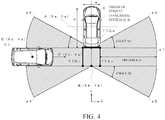
- the coordinates of the centers of the sector-shaped detection areas a2, a3 are A(Xa, Xa) and the coordinates of the centers of the sector-shaped detection areas a4, a5 are B(Xb, Xb). Further, central angles of the sector-shaped detection areas a2, a3 are ⁇ 1 and central angles of the sector-shaped detection areas a4, a5 are ⁇ 2. Note that ⁇ 1 and ⁇ 2 are set to, for example, 30°. Further, a distance d from a right end of the rectangular detection area a1 up to TTCr and a distance d from a left end of the rectangular detection area a1 up to TTCl are set to, for example, 3 m.
- TTCb Time to Collision
- TTCr two collision determination lines extending rearward in the Y direction from left and right ends of a rear portion of the vehicle C.
- the length of TTCl, TTCr is set to, for example, substantially the same as the whole width w of the host vehicle C. Of course, they may be set to a length other than this.
- the arithmetic processing part 13 refers to outputs of the other vehicle detecting parts 11a, 11b to detect that the other vehicle C1 exists in the detection area (in the example in Fig. 4 , in the rectangular detection area a1).
- the arithmetic processing part 13 When detecting that the other vehicle C1 exists in the detection area, the arithmetic processing part 13 detects a position C(Xc, Yc) and a relative speed V(Vx, Vy) of the other vehicle C1. Then, by referring to the detected position C(Xc, Yc) and relative speed V(Vx, Vy) of the other vehicle C1, the arithmetic processing part 13 determines whether or not there is a possibility that the other vehicle C1 intersects with any of TTCb, TTCl, TTCr. Then, in a case where there is a possibility of the intersection, the arithmetic processing part 13 gives a warning through the warning part 16 to alert the driver.
- a time T up to an instant when the other vehicle C1 intersects with TTCb, TTCl, TTCr is found, and in a case where this time T is smaller than a TTC set time, it is determined that there is a high possibility of the intersection.
- the TTC set time can be, for example, about two seconds.
- the arithmetic processing part 13 gives the warning through the warning part 16.
- a warning method include a method of lighting (or blinking) LED disposed on a side mirror or a rearview mirror and a method of making a warning sound from a speaker.
- the timing for stopping the warning can be, for example, when the vehicle stops or when the target goes out of the detection area.
- the warning is given from the warning part 16, which makes it possible to avoid the contact or collision with the other vehicle C1.
- the other vehicle C1 approaching the host vehicle C may be in a blind spot and cannot be seen due to the other vehicles standing still on the left or right, but even in such a case, it is possible to avoid the contact or collision with the other vehicle C1.
- the area directly behind the host vehicle C can be the detection area. This makes it possible to surely detect a target existing directly behind the host vehicle C.
- TTCb, TTCl, TTCr being the three collision determination lines are set and it is determined whether or not the other vehicle C1 will intersect with any of these, it is possible to surely detect the other vehicle C1 approaching from various directions or a stationary obstacle, unlike at the advance time. Further, in this embodiment, since it is determined, from the position and speed of the other vehicle, whether or not the other vehicle will intersect with any of the collision determination lines and the warning is given in the case where the other vehicle will intersect, the warning is not given in a case where there is a low possibility of the collision, which makes it possible to reduce unnecessary warnings.
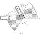
- the sector-shaped detection areas a2, a3 partly reaching the front side of the vehicle are set as illustrated in Fig. 4 , which makes it possible to surely detect the other vehicle C1 approaching from a lateral direction even when the vehicle C obliquely moves back as illustrated in, for example, Fig. 5 .
- the arithmetic processing part 13 refers to an output of the host vehicle state detecting part 12 to obtain the state of the host vehicle C.
- the arithmetic processing part 13 obtains information such as the vehicle speed and the state of the transmission output from the host vehicle state detecting part 12.
- Step S11 the arithmetic processing part 13 determines whether or not the host vehicle C is in a reverse state, and in the case of the reverse state (Step S11: Yes), goes to Step S13, and otherwise (Step S11: No), goes to Step S12. For example, in a case where the transmission is set in reverse (rear), the arithmetic processing part 13 determines as Yes to go to Step S13. Alternatively, in a case where a parking brake is released while the vehicle is standing still and the vehicle is moved back, it also determines as Yes to go to Step S13.
- the arithmetic processing part 13 executes the operation for the case where the host vehicle C advances.
- the arithmetic processing part 13 sets the detection areas illustrated in Fig. 2 , detects another vehicle traveling on a traffic lane adjacent to a traffic lane on which the host vehicle C is traveling, and in a case where there is a possibility that the other vehicle intersects with TTC1, TTC2, it executes the operation of giving the warning when the host vehicle C tries to make a lane change to the traffic lane on which the other vehicle is traveling (executes the advance-time operation mode).
- the arithmetic processing part 13 sets the reverse-time detection areas. In more detail, it sets the detection areas a1 to a5 illustrated in Fig. 3 to enter the reverse-time operation mode.
- the arithmetic processing part 13 refers to information supplied from the other vehicle detecting parts 11a, 11b to determine whether or not a target exists in any of the detection areas, and when determining that the target exists in any of the detection areas (Step S14: Yes), goes to Step S15, and otherwise, goes to Step S21. For example, in a case where the other vehicle C1 being the target exists in the rectangular detection area a1 as illustrated in Fig. 4 , it determines as Yes to go to Step S15.
- the arithmetic processing part 13 calculates the position (X, Y) of the target detected at Step S14.
- the arithmetic processing part 13 calculates the position C(X, Y) of the other vehicle C1 illustrated in Fig. 4 as, for example, a coordinate point on an orthogonal coordinate system whose origin is the center of the host vehicle C.
- the arithmetic processing part 13 calculates the speed (Vx, Vy) of the target detected at Step S14. In more detail, the arithmetic processing part 13 calculates the speed (Vx, Vy) of the other vehicle C1 illustrated in Fig. 4 .
- Step S17 the arithmetic processing part 13 determines whether or not the target will intersect with TTCb, and in a case where it will intersect (Step S17: Yes), goes to Step S20, and otherwise (Step S17: No), goes to Step S18. In more detail, it determines whether or not the target will intersect with TTCb, using X, Y, Vx, Vy of the target which are found by the above processing.
- Step S18 the arithmetic processing part 13 determines whether or not the target will intersect with TTCl, and when determining that it will intersect (Step S18: Yes), goes to Step S20, and otherwise (Step S18: No), goes to Step S19. In more detail, it determines whether or not the target will intersect with TTCl, using X, Y, Vx, Vy of the target which are found by the above processing.
- Step S19 the arithmetic processing part 13 determines whether or not the target will intersect with TTCr, and when determining that it will intersect (Step S19: Yes), goes to Step S20, and otherwise (Step S19: No), goes to Step S21. In more detail, it determines whether or not the target will intersect with TTCr, using X, Y, Vx, Vy of the target which are found by the above processing.
- the arithmetic processing part 13 gives the warning through the warning part 16 to alert the driver.
- Step S21 the arithmetic processing part 13 determines whether to repeat the processing or not, and when determining to repeat the processing (Step S21: Yes), returns to Step S10 to repeat the same processing as in the above-described case, and otherwise (Step S21: No), ends the processing.
- TTCb, TTCl, TTCr are set according to the whole width of the vehicle C and the width in the short-side direction of the rectangular detection area a1 as illustrated in Fig. 3 , but for example, as illustrated in Fig. 7 , they may be extended/contracted in the arrow directions according to, for example, the speed or the like of the host vehicle C.
- TTCb, TTCl, TTCr are set according to the whole width of the vehicle C and the width in the short-side direction of the rectangular detection area a1 as illustrated in Fig. 3 , but for example, as illustrated in Fig. 7 , they may be extended/contracted in the arrow directions according to, for example, the speed or the like of the host vehicle C.
- TTCl, TTCr are set to extend/contract in the forward direction of the vehicle according to, for example, the vehicle speed
- TTCb is set to extend/contract in the width direction of the vehicle C according to, for example, the vehicle speed. If TTCb, TTCl, TTCr are set to extend/contract in this manner, by, for example, making TTCb, TTCl, TTCr longer when the host vehicle C is moving back at a high speed than when it is moving back at a low speed, it is possible to more surely detect the possibility of the contact with the other vehicle C1.
- the three TTCb, TTCl, TTCr are set, but for example, only TTCb or only TTCl and TTCr may be set.
- detection areas in the case of the normal traveling are described, taking Fig. 2 as an example, but there may be other detection areas.
- angles ⁇ 1, ⁇ 2 are about 30° and the distance d is 3 m, but the angle or the distance may be set to another value.
- the sizes of the detection areas a1 to a5 are fixed, but the sizes of the detection areas a1 to a5 may be changed according to, for example, the traveling speed or the like of the host vehicle C. For example, the sizes of the detection areas may be increased in accordance with an increase in the speed of the host vehicle C.
- condition under which the warning is given may be changed according to the kind of a target.
- An example of a possible configuration is that, in a case where the target is a vehicle, its position and speed are found and it is determined whether or not the target will intersect with any of TTCb, TTCl, TTCr being the collision determination lines as previously described, and in a case where the target is a person, not only the aforesaid determination on whether or not the target will intersect with any of TTCb, TTCl, TTCr being the collision determination lines is made but also, for example, determination on whether or not the target exists in any of the rectangular detection area a1 and the sector-shaped detection areas a2 to a5 is made, and in a case where the person exists in any of these detection areas, the warning is given.
- This method can surely prevent the collision with the person or prevent the person from being involved.
- the determination is made based only on the state at the current point in time, but with a history of information in the past being stored, the determination may be made based on the history. This method can prevent the occurrence of erroneous determination even if a state of a parking area or the like suddenly changes.
- the warning part 16 gives the warning, but for example, the host vehicle C may be braked by automatic braking or the like.
- the observation areas that the other vehicle detecting parts 11a, 11b have are set such that their end portions are in contact or overlap with each other behind the host vehicle C, and in the case where they overlap with each other, the observation areas that the other vehicle detecting parts 11a, 11b have are prioritized, and the information observed in the higher-priority observation area is used preferentially, but another possible example is that, as for the overlapping observation areas, arithmetic processing different from that for a non-overlapping observation area is executed and higher-accuracy information is generated by collating pieces of information observed in the respective observation areas.
- TTCl, TTCr as the collision determination lines are set so as to be parallel to the front-rear direction of the vehicle, but TTCl, TTCr may be set so as to be oblique to the front-rear direction of the vehicle.
- TTCl, TTCr as the collision determination lines may be set in a direction perpendicular to the road 20 as illustrated in Fig. 8 .
- a method of such an oblique setting may be, for example, to detect the direction of the road 20 when the host vehicle is traveling on the road 20 and store the direction, or to estimate the direction using a parked vehicle.
- the oblique setting is achieved by adjusting the angle of TTCl, TTCr based on an angle difference from the stored or estimated direction when the vehicle is to be parked.
- this is achieved by detecting a traveling direction of another vehicle traveling in parallel to the center lines 21 and the angle of the host vehicle and adjusting the angle of TTCl, TTCr to an angle perpendicular to the other vehicle.
- TTCl, TTCr it is possible to set TTCl, TTCr to a more optimum angle by finding an average traveling direction from a plurality of traveling vehicles or parked vehicles and adjusting the angle of TTCl TTCr to an angle perpendicular to the average traveling direction. Further, in the case where the host vehicle moves back, a rudder angle may be detected by a rudder angle sensor and the angle and length of TTCl, TTCr may be adjusted based on the detected direction (reverse direction).
Abstract
Description
- The present invention relates to a monitoring device and a monitoring method.
- In the art disclosed in
Patent Document 1, after the distance from and the direction of a target is detected using a radar as a range finding means, the distance and the direction are mapped in an orthogonal coordinate space by coordinate transformation, whereby a coordinate value is calculated, and in a case where the target is within a predetermined alarm area around the host vehicle, an alarm is given to alert a driver. - Further, in the art disclosed in
Patent Document 2, it is determined whether or not a target has entered a predetermined area in a detection area behind the host vehicle, and when it is determined that the target has entered the predetermined area, notification is stopped. -
- Patent Document 1: Japanese Patent Application Laid-open No.
2003-215241 - Patent Document 2:
WO2013/046246 - However, the art disclosed in
Patent Document 1 has a problem that, when the vehicle is moved back in, for example, a parking area or the like, it is not possible to surely detect other vehicles approaching from various directions and moving across behind the host vehicle, an obstacle present behind the host vehicle, and so on. - Further, the art disclosed in
Patent Document 2 has a problem that, when the vehicle is moved back, it is not possible to detect a stationary target existing directly behind the host vehicle or a moving target approaching from directly behind. - It is an object of the present invention to provide a monitoring device and a monitoring method capable of surely detecting a target existing around the host vehicle when the vehicle is moved back.
- To solve the aforesaid problems, the present invention is a monitoring device that monitors a state around a vehicle, the monitoring device characterized by including: a transmitting/receiving part that transmits an electromagnetic wave to receive a reflected wave from a target; a detecting part that detects the target existing in a rear area including an area directly behind the vehicle and the target existing in rear left and right sides of the vehicle, by referring to the reflected wave received from the target by the transmitting/receiving part; and a determining part that determines whether or not there is a possibility of contact or collision between the target detected by the detecting part and the vehicle.
- Such a configuration enables the sure detection of a target existing around the host vehicle when the vehicle is moved back.
- Further, the present invention is characterized by including a warning part that gives a warning when the determining part determines that the contact or the collision between the target and the vehicle will occur.
- Such a configuration makes it possible to surely notify a user of the possibility of the contact or the collision with the target.
- Further, the present invention is characterized in that the determining part sets at least two collision determination lines extending rearward in terms of a traveling direction of the vehicle from vicinities of left and right ends of a rear portion of the vehicle and the collision determination line which extends along the rear portion of the vehicle in a direction perpendicular to the traveling direction, and determines whether or not the target will intersect with any of the three collision determination lines.
- Such a configuration makes it possible to more surely determine the possibility of the contact or the collision between the target and the host vehicle.
- Further, the present invention is characterized in that: the detecting part detects the target existing in a detection area located behind the vehicle and having a rectangular shape whose longitudinal direction is the direction perpendicular to the traveling direction of the vehicle and in the four detection areas each having a sector shape whose radius has a length substantially half the length of a side in the longitudinal direction of the detection area having the rectangular shape and whose center is substantially a midpoint of the longitudinal-direction side; and the determining part determines whether or not the target existing in the detection area having the rectangular shape or in any of the four detection areas having the sector shape will intersect with any of the collision determination lines.
- Such a configuration makes it possible to surely detect a target approaching the host vehicle from various directions.
- Further, the present invention is characterized in that the collision determination lines are each extended/contracted according to a speed of the vehicle.
- Such a configuration makes it possible to give an appropriate warning according to the speed of the vehicle.
- Further, the present invention is a monitoring method of monitoring a state around a vehicle, the monitoring method characterized by including: a transmitting/receiving step of transmitting an electromagnetic wave to receive a reflected wave from a target; a detecting step of detecting the target existing in a rear area including an area directly behind the vehicle and the target existing in rear left and right sides of the vehicle, by referring to the reflected wave received from the target in the transmitting/receiving step; and a determining step of determining whether or not there is a possibility of contact or collision between the target detected in the detecting step and the vehicle.
- Such a method makes it possible to surely detect a target existing around the host vehicle when the vehicle is moved back.
- According to the present invention, it is possible to provide a monitoring device and a monitoring method capable of surely detecting a target existing around a host vehicle when the vehicle is moved back.
-
-
Fig. 1 is a diagram illustrating a configuration example of a monitoring device in an embodiment of the present invention. -
Fig. 2 is an explanatory view of an operation at the time of normal traveling in the embodiment illustrated inFig. 1 . -
Fig. 3 is an explanatory view of an operation at the time of reverse movement in the embodiment illustrated inFig. 1 . -
Fig. 4 is another explanatory view of the operation at the time of the reverse movement in the embodiment illustrated inFig. 1 . -
Fig. 5 is an explanatory view of an operation at the time of reverse movement in an oblique direction in the embodiment illustrated inFig. 1 . -
Fig. 6 is an explanatory flowchart of an example of processing executed in the embodiment illustrated inFig. 1 . -
Fig. 7 is another explanatory view of an operation at the time of the reverse movement in the embodiment illustrated inFig. 1 . -
Fig. 8 is an explanatory view of another embodiment of the present invention. - Next, an embodiment of the present invention will be described.
-
Fig. 1 is a diagram illustrating a configuration example of a monitoring device according to the embodiment of the present invention. As illustrated in this drawing, themonitoring device 10 includes, as main constituent elements, other vehicle detecting parts 11a, 11b, a host vehiclestate detecting part 12, anarithmetic processing part 13, asteering detecting part 14, a directionindication detecting part 15, and awarning part 16. - Here, the other vehicle detecting parts 11a, 11b are each constituted by, for example, a radar device or the like that irradiates another vehicle with a radio wave and from its reflected wave, detects the position, speed, and so on of the other vehicle. The other vehicle detecting part 11a is disposed, for example, on a rear left side of a vehicle, and the other vehicle detecting part 11b is disposed, for example, on a rear right side of the vehicle. Further, observation areas (areas in which a target can be observed) of the respective other vehicle detecting part 11a and other vehicle detecting part 11b are set so as to be in contact with or overlap with each other at their end portions on a rearward side of the host vehicle C.
- The host vehicle
state detecting part 12 is constituted by, for example, a vehicle speed sensor, a yaw-axis sensor, a sensor that detects a state of a transmission, or the like, and it detects a traveling state of the host vehicle to notify the detected state to thearithmetic processing part 13. - The
arithmetic processing part 13 detects a four-wheeled vehicle or a two-wheeled vehicle traveling behind and determines whether or not there is a possibility of contact or collision, based on information supplied from the other vehicle detecting parts 11a, 11b, the host vehiclestate detecting part 12, thesteering detecting part 14, and the directionindication detecting part 15, and when determining that there is a possibility of the contact or the like, gives a warning through thewarning part 16. Further, thearithmetic processing part 13 detects an obstacle existing behind the host vehicle when the host vehicle is to be parked in a parking area or the like, determines whether or not there is a possibility of contact or the like with the obstacle, and when determining that there is a possibility of the contact or the like, gives a warning through thewarning part 16. - The
warning part 16 is constituted by, for example, a speaker which makes a warning sound, LED (Light Emitting Diode) which blinks on and off, or the like, and alerts a driver by making the warning sound when thearithmetic processing part 13 determines that there is a possibility of the collision or contact. - Next, operations of the embodiment of the present invention will be described. The embodiment of the present invention has at least two operation modes: an advance-time operation mode where a target existing behind is detected when the host vehicle advances; and a reverse-time operation mode where a target existing behind is detected at the time of the reverse movement. In each of the operation modes, detection areas where to detect another vehicle or the like existing behind are set, another vehicle or the like existing in any of the detection areas is detected, it is determined whether or not the detected other vehicle will come into contact or collide with the host vehicle, and when it is determined that the contact or the like will occur, the
warning part 16 gives a warning to alert the driver. -
Fig. 2 is a view illustrating an example of detection areas where to detect a target existing behind the host vehicle C in the advance-time operation mode. InFig. 2 , the whole width of the host vehicle C is w and its whole length is h. Further, the center of the vehicle C is an origin (0, 0) of an orthogonal coordinate system. Further, behind the host vehicle C, detection areas al, ar are set, and on front portions of the respective areas, TTC1, TTC2 (Time to Collision) are set as collision determination lines. When the host vehicle C is advancing, thearithmetic processing part 13 sets the detection areas al, ar having a rectangular shape as illustrated inFig. 2 behind the vehicle. Note that the detection areas illustrated inFig. 2 are set by thearithmetic processing parts 13 through arithmetic processing, in the observation areas which are areas where to observe a target by the two other vehicle detecting parts 11a, 11b illustrated inFig. 1 . - Note that these detection areas al, ar are detection areas where to detect other vehicles traveling on traffic lanes adjacent to a traffic lane on which the host vehicle C is traveling. In a case where the other vehicle detected by the other vehicle detecting part 11a, 11b exists in the detection area al, ar, the
arithmetic processing part 13 detects the position and speed of the other vehicle and determines whether or not the other vehicle will intersect with TTC1, TTC2. Then, when it is determined that it will intersect, thewarning part 16 gives the warning if the driver operates a steering wheel or operates a direction indicator in an attempt to move toward the lane where the other vehicle is traveling. - In more detail, the
arithmetic processing part 13 gives the warning through thewarning part 16 in a case where thesteering detecting part 14 detects that the driver operates the steering handle for moving to the lane where the other vehicle is traveling or in a case where the directionindication detecting part 15 detects that the driver operates the direction indicator toward the lane where the other vehicle is traveling. This can avoid the contact or collision of the host vehicle C with the vehicle behind. - Next,
Fig. 3 is a view illustrating an example of detection areas where to detect a target existing behind the host vehicle C in the reverse-time operation mode. In more detail,Fig. 3 is a view illustrating an example of detection areas in a case where the host vehicle C moves back in, for example, a parking area or the like. In a case where thearithmetic processing part 13 determines that the transmission of the host vehicle C is set in reverse (rear) by referring to an output of the host vehiclestate detecting part 12, thearithmetic processing part 13 changes the setting from the detection areas illustrated inFig. 2 to the detection areas illustrated inFig. 3 . - In the example in
Fig. 3 , the detection areas include a detection area a1 located behind the host vehicle C and having a rectangular shape whose longitudinal direction is an X direction (direction perpendicular to the traveling direction of the host vehicle C) (hereinafter, simply referred to as a "rectangular detection area a1") and detection areas a2 to a5 each having a sector shape whose radius has a length substantially half the length of a longitudinal-direction side of the rectangular detection area a1 and whose center is located near the midpoint of the rectangular detection area a1 (hereinafter, simply referred to as "sector-shaped detection areas a2 to a5"). In more detail, the sector-shaped detection area a2 has a sector shape whose center is substantially the midpoint of an upper (upper inFig. 3 ) side of the rectangular detection area a1 and whose width gets wider as it goes more apart leftward from the host vehicle C. The sector-shaped detection area a3 has a sector shape whose center is substantially the midpoint of the upper side of the rectangular detection area a1 and whose width gets wider as it goes more apart rightward from the host vehicle C. The sector-shaped detection area a4 has a sector shape whose center is substantially the midpoint of a lower (lower inFig. 3 ) side of the rectangular detection area a1 and whose width gets wider as it goes more apart leftward from the host vehicle C. The sector-shaped detection area a5 has a sector shape whose center is substantially the midpoint of the lower side of the rectangular detection area a1 and whose width gets wider as it goes more apart rightward from the host vehicle C. - The left half of the rectangular detection area a1 and the sector-shaped detection areas a2, a4 are set in the observation area of the other vehicle detecting part 11a illustrated in
Fig. 1 , and the right half of the rectangular detection area a1 and the sector-shaped detection areas a3, a5 are set in the observation area of the other vehicle detecting part 11b illustrated inFig. 1 . Further, in the advance-time operation mode illustrated inFig. 2 , the detection areas al, ar are independent areas not overlapping with each other, but in the reverse-time operation mode illustrated inFig. 3 , the left half of the rectangular detection area a1 and the sector-shaped detection areas a2, a4 are set to be partly in contact or overlap with the right half of the rectangular detection area a1 and the sector-shaped detection areas a3, a5. As previously described, the end portions of the observation areas of the other vehicle detecting part 11a and the other vehicle detecting part 11b are set to be in contact or overlap with each other behind the host vehicle C and accordingly, an area directly behind the host vehicle C is covered by an area in the vicinity of the center of the detection area a1 as illustrated inFig. 3 . In a case where the end portions of the observation areas of the other vehicle detecting part 11a and the other vehicle detecting part 11b overlap with each other, one of the other vehicle detecting part 11a and the other vehicle detecting part 11b is set as a master and the other is set as a slave, and pieces of information obtained from their overlapping observation areas are prioritized, which can prevent a processing speed from lowering due to redundant processing and prevent the occurrence of erroneous detection. - The coordinates of the centers of the sector-shaped detection areas a2, a3 are A(Xa, Xa) and the coordinates of the centers of the sector-shaped detection areas a4, a5 are B(Xb, Xb). Further, central angles of the sector-shaped detection areas a2, a3 are θ1 and central angles of the sector-shaped detection areas a4, a5 are θ2. Note that θ1 and θ2 are set to, for example, 30°. Further, a distance d from a right end of the rectangular detection area a1 up to TTCr and a distance d from a left end of the rectangular detection area a1 up to TTCl are set to, for example, 3 m.
- Behind the vehicle C, there are set TTCb (Time to Collision) as a collision determination line extending in the X direction and having substantially the same length as the whole width w of the host vehicle C and TTCl, TTCr as two collision determination lines extending rearward in the Y direction from left and right ends of a rear portion of the vehicle C. Note that the length of TTCl, TTCr is set to, for example, substantially the same as the whole width w of the host vehicle C. Of course, they may be set to a length other than this.
- Suppose that, for example, another vehicle C1 approaches the host vehicle C from the left side as illustrated in
Fig. 4 in a state where the detection areas and the collision determination lines illustrated inFig. 3 are set. In such a case, thearithmetic processing part 13 refers to outputs of the other vehicle detecting parts 11a, 11b to detect that the other vehicle C1 exists in the detection area (in the example inFig. 4 , in the rectangular detection area a1). - When detecting that the other vehicle C1 exists in the detection area, the
arithmetic processing part 13 detects a position C(Xc, Yc) and a relative speed V(Vx, Vy) of the other vehicle C1. Then, by referring to the detected position C(Xc, Yc) and relative speed V(Vx, Vy) of the other vehicle C1, thearithmetic processing part 13 determines whether or not there is a possibility that the other vehicle C1 intersects with any of TTCb, TTCl, TTCr. Then, in a case where there is a possibility of the intersection, thearithmetic processing part 13 gives a warning through thewarning part 16 to alert the driver. In more detail, from the position C(Xc, Yc) and the relative speed V(Vx, Vy) of the other vehicle C1, a time T up to an instant when the other vehicle C1 intersects with TTCb, TTCl, TTCr is found, and in a case where this time T is smaller than a TTC set time, it is determined that there is a high possibility of the intersection. Note that the TTC set time can be, for example, about two seconds. In the case of T < TTC set time, thearithmetic processing part 13 gives the warning through thewarning part 16. Since the driver, as a result, can be notified that the other vehicle C1 is approaching, he/she is capable of avoiding the contact or collision with the other vehicle C1 by returning an accelerator pedal or operating a brake pedal. Incidentally, examples of a warning method include a method of lighting (or blinking) LED disposed on a side mirror or a rearview mirror and a method of making a warning sound from a speaker. Incidentally, the timing for stopping the warning can be, for example, when the vehicle stops or when the target goes out of the detection area. - As described above, according to the embodiment of the present invention, in the case where it is determined that the other vehicle C1 is in any of the detection areas a1 to a5 and will intersect with any of TTCb, TTC1, TTCr when the host vehicle C is going to move back or is moving back in, for example, a parking area or the like, the warning is given from the
warning part 16, which makes it possible to avoid the contact or collision with the other vehicle C1. In particular, at the time of the reverse movement in, for example, a parking area or the like while not-illustrated other vehicles are standing still side by side on the left and right, the other vehicle C1 approaching the host vehicle C may be in a blind spot and cannot be seen due to the other vehicles standing still on the left or right, but even in such a case, it is possible to avoid the contact or collision with the other vehicle C1. - Further, in this embodiment, since the observation areas of the respective other vehicle detecting parts 11a, 11b are disposed such that their end portions behind the vehicle are in contact or overlap with each other as illustrated in
Fig. 3 , the area directly behind the host vehicle C can be the detection area. This makes it possible to surely detect a target existing directly behind the host vehicle C. - Further, in this embodiment, since TTCb, TTCl, TTCr being the three collision determination lines are set and it is determined whether or not the other vehicle C1 will intersect with any of these, it is possible to surely detect the other vehicle C1 approaching from various directions or a stationary obstacle, unlike at the advance time. Further, in this embodiment, since it is determined, from the position and speed of the other vehicle, whether or not the other vehicle will intersect with any of the collision determination lines and the warning is given in the case where the other vehicle will intersect, the warning is not given in a case where there is a low possibility of the collision, which makes it possible to reduce unnecessary warnings. For example, in the art disclosed in
Patent Document 2, since the warning is given in the case where a target exists in the notification target area, the warning is given even in a case where the other vehicle is standing still and there is no possibility of the collision. In this embodiment, on the other hand, the warning is not given in a case where the other vehicle is standing still and will not intersect with any of the collision determination lines, which makes it possible to prevent an unnecessary warning. - Further, in this embodiment, the sector-shaped detection areas a2, a3 partly reaching the front side of the vehicle are set as illustrated in
Fig. 4 , which makes it possible to surely detect the other vehicle C1 approaching from a lateral direction even when the vehicle C obliquely moves back as illustrated in, for example,Fig. 5 . - Next, details of processing executed in the embodiment illustrated in
Fig. 1 will be described with reference toFig. 6 . When the processing of the flowchart illustrated inFig. 6 is started, the following steps are executed. - At Step S10, the
arithmetic processing part 13 refers to an output of the host vehiclestate detecting part 12 to obtain the state of the host vehicle C. For example, thearithmetic processing part 13 obtains information such as the vehicle speed and the state of the transmission output from the host vehiclestate detecting part 12. - At Step S11, the
arithmetic processing part 13 determines whether or not the host vehicle C is in a reverse state, and in the case of the reverse state (Step S11: Yes), goes to Step S13, and otherwise (Step S11: No), goes to Step S12. For example, in a case where the transmission is set in reverse (rear), thearithmetic processing part 13 determines as Yes to go to Step S13. Alternatively, in a case where a parking brake is released while the vehicle is standing still and the vehicle is moved back, it also determines as Yes to go to Step S13. - At Step S12, the
arithmetic processing part 13 executes the operation for the case where the host vehicle C advances. In more detail, thearithmetic processing part 13 sets the detection areas illustrated inFig. 2 , detects another vehicle traveling on a traffic lane adjacent to a traffic lane on which the host vehicle C is traveling, and in a case where there is a possibility that the other vehicle intersects with TTC1, TTC2, it executes the operation of giving the warning when the host vehicle C tries to make a lane change to the traffic lane on which the other vehicle is traveling (executes the advance-time operation mode). - At Step S13, the
arithmetic processing part 13 sets the reverse-time detection areas. In more detail, it sets the detection areas a1 to a5 illustrated inFig. 3 to enter the reverse-time operation mode. - At Step S14, the
arithmetic processing part 13 refers to information supplied from the other vehicle detecting parts 11a, 11b to determine whether or not a target exists in any of the detection areas, and when determining that the target exists in any of the detection areas (Step S14: Yes), goes to Step S15, and otherwise, goes to Step S21. For example, in a case where the other vehicle C1 being the target exists in the rectangular detection area a1 as illustrated inFig. 4 , it determines as Yes to go to Step S15. - At Step S15, the
arithmetic processing part 13 calculates the position (X, Y) of the target detected at Step S14. In more detail, thearithmetic processing part 13 calculates the position C(X, Y) of the other vehicle C1 illustrated inFig. 4 as, for example, a coordinate point on an orthogonal coordinate system whose origin is the center of the host vehicle C. - At Step S16, the
arithmetic processing part 13 calculates the speed (Vx, Vy) of the target detected at Step S14. In more detail, thearithmetic processing part 13 calculates the speed (Vx, Vy) of the other vehicle C1 illustrated inFig. 4 . - At Step S17, the
arithmetic processing part 13 determines whether or not the target will intersect with TTCb, and in a case where it will intersect (Step S17: Yes), goes to Step S20, and otherwise (Step S17: No), goes to Step S18. In more detail, it determines whether or not the target will intersect with TTCb, using X, Y, Vx, Vy of the target which are found by the above processing. - At Step S18, the
arithmetic processing part 13 determines whether or not the target will intersect with TTCl, and when determining that it will intersect (Step S18: Yes), goes to Step S20, and otherwise (Step S18: No), goes to Step S19. In more detail, it determines whether or not the target will intersect with TTCl, using X, Y, Vx, Vy of the target which are found by the above processing. - At Step S19, the
arithmetic processing part 13 determines whether or not the target will intersect with TTCr, and when determining that it will intersect (Step S19: Yes), goes to Step S20, and otherwise (Step S19: No), goes to Step S21. In more detail, it determines whether or not the target will intersect with TTCr, using X, Y, Vx, Vy of the target which are found by the above processing. - At Step S20, the
arithmetic processing part 13 gives the warning through thewarning part 16 to alert the driver. - At Step S21, the
arithmetic processing part 13 determines whether to repeat the processing or not, and when determining to repeat the processing (Step S21: Yes), returns to Step S10 to repeat the same processing as in the above-described case, and otherwise (Step S21: No), ends the processing. - According to the above-described flowchart, it is possible to achieve the operations previously described with reference to
Fig. 1 . - The above embodiment is only an example, and it goes without saying that the present invention is not limited to the above-described cases. For example, in the above-described embodiment, TTCb, TTCl, TTCr are set according to the whole width of the vehicle C and the width in the short-side direction of the rectangular detection area a1 as illustrated in
Fig. 3 , but for example, as illustrated inFig. 7 , they may be extended/contracted in the arrow directions according to, for example, the speed or the like of the host vehicle C. In more detail, in the example inFig. 7 , TTCl, TTCr are set to extend/contract in the forward direction of the vehicle according to, for example, the vehicle speed, and TTCb is set to extend/contract in the width direction of the vehicle C according to, for example, the vehicle speed. If TTCb, TTCl, TTCr are set to extend/contract in this manner, by, for example, making TTCb, TTCl, TTCr longer when the host vehicle C is moving back at a high speed than when it is moving back at a low speed, it is possible to more surely detect the possibility of the contact with the other vehicle C1. - Further, in the above-described embodiment, the three TTCb, TTCl, TTCr are set, but for example, only TTCb or only TTCl and TTCr may be set.
- Further, the detection areas in the case of the normal traveling are described, taking
Fig. 2 as an example, but there may be other detection areas. - Further, in the above-described embodiment, in
Fig. 3 , the angles θ1, θ2 are about 30° and the distance d is 3 m, but the angle or the distance may be set to another value. - Further, the sizes of the detection areas a1 to a5 are fixed, but the sizes of the detection areas a1 to a5 may be changed according to, for example, the traveling speed or the like of the host vehicle C. For example, the sizes of the detection areas may be increased in accordance with an increase in the speed of the host vehicle C.
- Further, in the above-described embodiment, the description is given, taking the case where the other vehicle C1 being the target is moving, as an example, but it goes without saying that the present invention is applicable even to a case where the target is standing still.
- Further, the condition under which the warning is given may be changed according to the kind of a target. An example of a possible configuration is that, in a case where the target is a vehicle, its position and speed are found and it is determined whether or not the target will intersect with any of TTCb, TTCl, TTCr being the collision determination lines as previously described, and in a case where the target is a person, not only the aforesaid determination on whether or not the target will intersect with any of TTCb, TTCl, TTCr being the collision determination lines is made but also, for example, determination on whether or not the target exists in any of the rectangular detection area a1 and the sector-shaped detection areas a2 to a5 is made, and in a case where the person exists in any of these detection areas, the warning is given. This method can surely prevent the collision with the person or prevent the person from being involved.
- Further, in the flowchart illustrated in
Fig. 6 , the determination is made based only on the state at the current point in time, but with a history of information in the past being stored, the determination may be made based on the history. This method can prevent the occurrence of erroneous determination even if a state of a parking area or the like suddenly changes. - Further, in the above-described embodiment, in the case where it is determined that there is a possibility of the contact or collision with a target, the
warning part 16 gives the warning, but for example, the host vehicle C may be braked by automatic braking or the like. - Further, in the above-described embodiment, the observation areas that the other vehicle detecting parts 11a, 11b have are set such that their end portions are in contact or overlap with each other behind the host vehicle C, and in the case where they overlap with each other, the observation areas that the other vehicle detecting parts 11a, 11b have are prioritized, and the information observed in the higher-priority observation area is used preferentially, but another possible example is that, as for the overlapping observation areas, arithmetic processing different from that for a non-overlapping observation area is executed and higher-accuracy information is generated by collating pieces of information observed in the respective observation areas.
- Further, in the above-described embodiment, TTCl, TTCr as the collision determination lines are set so as to be parallel to the front-rear direction of the vehicle, but TTCl, TTCr may be set so as to be oblique to the front-rear direction of the vehicle. For example, in a case where
parking lines 22 are drawn obliquely to a shoulder of aroad 20 havingcenter lines 21 as illustrated inFig. 8 , TTCl, TTCr as the collision determination lines may be set in a direction perpendicular to theroad 20 as illustrated inFig. 8 . Incidentally, a method of such an oblique setting may be, for example, to detect the direction of theroad 20 when the host vehicle is traveling on theroad 20 and store the direction, or to estimate the direction using a parked vehicle. The oblique setting is achieved by adjusting the angle of TTCl, TTCr based on an angle difference from the stored or estimated direction when the vehicle is to be parked. Alternatively, this is achieved by detecting a traveling direction of another vehicle traveling in parallel to thecenter lines 21 and the angle of the host vehicle and adjusting the angle of TTCl, TTCr to an angle perpendicular to the other vehicle. Incidentally, it is possible to set TTCl, TTCr to a more optimum angle by finding an average traveling direction from a plurality of traveling vehicles or parked vehicles and adjusting the angle of TTCl TTCr to an angle perpendicular to the average traveling direction. Further, in the case where the host vehicle moves back, a rudder angle may be detected by a rudder angle sensor and the angle and length of TTCl, TTCr may be adjusted based on the detected direction (reverse direction). -
- 10
- monitoring device
- 11a, 11b
- other vehicle detecting part
- 12
- host vehicle state detecting part
- 13
- arithmetic processing part
- 14
- steering detecting part
- 15
- direction indication detecting part
- 16
- warning part
Claims (6)
- A monitoring device that monitors a state around a vehicle, the monitoring device comprising:a transmitting/receiving part that transmits an electromagnetic wave to receive a reflected wave from a target;a detecting part that detects the target existing in a rear area including an area directly behind the vehicle and the target existing in rear left and right sides of the vehicle, by referring to the reflected wave received from the target by the transmitting/receiving part; anda determining part that determines whether or not there is a possibility of contact or collision between the target detected by the detecting part and the vehicle.
- The monitoring device according to claim 1, comprising a warning part that gives a warning when the determining part determines that the contact or the collision between the target and the vehicle will occur.
- The monitoring device according to claim 1 or 2, wherein the determining part sets at least two collision determination lines extending rearward in terms of a traveling direction of the vehicle from vicinities of left and right ends of a rear portion of the vehicle and the collision determination line which extends along the rear portion of the vehicle in a direction perpendicular to the traveling direction, and determines whether or not the target will intersect with any of the three collision determination lines.
- The monitoring device according to claim 3, wherein:the detecting part detects the target existing in a detection area located behind the vehicle and having a rectangular shape whose longitudinal direction is the direction perpendicular to the traveling direction of the vehicle and in the four detection areas each having a sector shape whose radius has a length substantially half the length of a side in the longitudinal direction of the detection area having the rectangular shape and whose center is substantially a midpoint of the longitudinal-direction side; andthe determining part determines whether or not the target existing in the detection area having the rectangular shape or in any of the four detection areas having the sector shape will intersect with any of the collision determination lines.
- The monitoring device according to claim 3 or 4, wherein the collision determination lines are each extended/contracted according to a speed of the vehicle.
- A monitoring method of monitoring a state around a vehicle, the monitoring method comprising:a transmitting/receiving step of transmitting an electromagnetic wave to receive a reflected wave from a target;a detecting step of detecting the target existing in a rear area including an area directly behind the vehicle and the target existing in rear left and right sides of the vehicle, by referring to the reflected wave received from the target in the transmitting/receiving step; anda determining step of determining whether or not there is a possibility of contact or collision between the target detected in the detecting step and the vehicle.
Applications Claiming Priority (2)
| Application Number | Priority Date | Filing Date | Title |
|---|---|---|---|
| JP2016072888 | 2016-03-31 | ||
| PCT/JP2017/013515 WO2017170979A1 (en) | 2016-03-31 | 2017-03-31 | Monitoring device and monitoring method |
Publications (2)
| Publication Number | Publication Date |
|---|---|
| EP3438947A1 true EP3438947A1 (en) | 2019-02-06 |
| EP3438947A4 EP3438947A4 (en) | 2019-07-03 |
Family
ID=59965970
Family Applications (1)
| Application Number | Title | Priority Date | Filing Date |
|---|---|---|---|
| EP17775511.3A Ceased EP3438947A4 (en) | 2016-03-31 | 2017-03-31 | Monitoring device and monitoring method |
Country Status (5)
| Country | Link |
|---|---|
| US (1) | US20190033443A1 (en) |
| EP (1) | EP3438947A4 (en) |
| JP (1) | JP6858178B2 (en) |
| CN (1) | CN108885839A (en) |
| WO (1) | WO2017170979A1 (en) |
Cited By (2)
| Publication number | Priority date | Publication date | Assignee | Title |
|---|---|---|---|---|
| EP3576071A3 (en) * | 2018-06-01 | 2020-03-04 | Mazda Motor Corporation | Alarm system for vehicle |
| EP3576073A3 (en) * | 2018-06-01 | 2020-03-18 | Mazda Motor Corporation | Alarm system for vehicle |
Families Citing this family (3)
| Publication number | Priority date | Publication date | Assignee | Title |
|---|---|---|---|---|
| KR102589934B1 (en) * | 2018-09-13 | 2023-10-17 | 현대모비스 주식회사 | Apparatus and method for adjusting a warning condition |
| JP7192600B2 (en) * | 2019-03-20 | 2022-12-20 | 株式会社デンソー | alarm device |
| JP7310488B2 (en) | 2019-09-25 | 2023-07-19 | スズキ株式会社 | Driving support device |
Family Cites Families (23)
| Publication number | Priority date | Publication date | Assignee | Title |
|---|---|---|---|---|
| JP2000284048A (en) * | 1999-03-29 | 2000-10-13 | Toyota Motor Corp | Monitoring device around vehicle |
| AU2211201A (en) * | 1999-12-23 | 2001-07-09 | Thomas Bertram Poole | Following distance warning system for a vehicle |
| US7068211B2 (en) * | 2000-02-08 | 2006-06-27 | Cambridge Consultants Limited | Methods and apparatus for obtaining positional information |
| US6784791B2 (en) * | 2002-07-25 | 2004-08-31 | Ford Global Technologies, Llc | Potential collision detection and parking aid system |
| JP2006201013A (en) * | 2005-01-20 | 2006-08-03 | Hitachi Ltd | On-vehicle radar |
| US8364366B2 (en) * | 2005-06-24 | 2013-01-29 | Deere & Company | System and method for providing a safety zone associated with a vehicle |
| DE102006020631A1 (en) * | 2006-05-04 | 2007-11-08 | Valeo Schalter Und Sensoren Gmbh | Control system for direction indicator in vehicle with both visual and radar monitoring of nearby vehicles |
| JP4613906B2 (en) * | 2006-12-14 | 2011-01-19 | トヨタ自動車株式会社 | Vehicle periphery monitoring device |
| JP5338398B2 (en) * | 2009-03-12 | 2013-11-13 | トヨタ自動車株式会社 | Driving support device |
| US7978096B2 (en) * | 2009-04-28 | 2011-07-12 | Ford Global Technologies, Llc | Parking angle determination and cross traffic alert |
| JP5505702B2 (en) * | 2010-02-24 | 2014-05-28 | アイシン精機株式会社 | Vehicle periphery monitoring device |
| CN102906593B (en) * | 2010-05-19 | 2015-06-17 | 三菱电机株式会社 | Vehicle rear-view observation device |
| DE102012201282A1 (en) * | 2011-01-31 | 2012-08-02 | Denso Corporation | Antenna device, radar device and vehicle radar system |
| JP5722127B2 (en) * | 2011-06-07 | 2015-05-20 | 株式会社小松製作所 | Work vehicle perimeter monitoring device |
| DE102011104740A1 (en) * | 2011-06-17 | 2012-03-29 | Daimler Ag | Blind spot monitoring method for vehicle i.e. passenger car, involves performing recognition of objects in surrounding region of vehicle based on verification of radar data of radar detectors and ultrasound data of ultrasonic sensors |
| JP2013045142A (en) * | 2011-08-22 | 2013-03-04 | Toyota Motor Corp | Approach warning device, approach warning method, program, and medium |
| US9064408B2 (en) * | 2011-09-26 | 2015-06-23 | Toyota Jidosha Kabushiki Kaisha | Rear cross traffic alert device |
| US20140354450A1 (en) * | 2012-02-10 | 2014-12-04 | Yoshihiko Takahashi | Warning device |
| JP5928486B2 (en) * | 2012-02-14 | 2016-06-01 | 日産自動車株式会社 | Travel control device and travel control method |
| WO2014064831A1 (en) * | 2012-10-26 | 2014-05-01 | トヨタ自動車 株式会社 | Driving assistance device and driving assistance method |
| CN203666504U (en) * | 2013-10-29 | 2014-06-25 | 盈佳科技(长春)有限公司 | Automobile dead area radar warning device |
| CN104691545B (en) * | 2013-12-04 | 2017-10-24 | 财团法人车辆研究测试中心 | Adaptability vehicle collision avoidance method |
| JP6413240B2 (en) * | 2014-01-08 | 2018-10-31 | 株式会社デンソー | Vehicle control device and vehicle |
-
2017
- 2017-03-31 EP EP17775511.3A patent/EP3438947A4/en not_active Ceased
- 2017-03-31 WO PCT/JP2017/013515 patent/WO2017170979A1/en active Application Filing
- 2017-03-31 JP JP2018509643A patent/JP6858178B2/en active Active
- 2017-03-31 CN CN201780021600.8A patent/CN108885839A/en active Pending
-
2018
- 2018-09-28 US US16/147,317 patent/US20190033443A1/en not_active Abandoned
Cited By (2)
| Publication number | Priority date | Publication date | Assignee | Title |
|---|---|---|---|---|
| EP3576071A3 (en) * | 2018-06-01 | 2020-03-04 | Mazda Motor Corporation | Alarm system for vehicle |
| EP3576073A3 (en) * | 2018-06-01 | 2020-03-18 | Mazda Motor Corporation | Alarm system for vehicle |
Also Published As
| Publication number | Publication date |
|---|---|
| WO2017170979A1 (en) | 2017-10-05 |
| JPWO2017170979A1 (en) | 2019-02-14 |
| CN108885839A (en) | 2018-11-23 |
| US20190033443A1 (en) | 2019-01-31 |
| JP6858178B2 (en) | 2021-04-14 |
| EP3438947A4 (en) | 2019-07-03 |
Similar Documents
| Publication | Publication Date | Title |
|---|---|---|
| EP3438947A1 (en) | Monitoring device and monitoring method | |
| CN109532829B (en) | Anti-collision control device and method thereof | |
| US9415776B2 (en) | Enhanced lane departure system | |
| CN107787282B (en) | Cognitive driver assistance with variable assistance for automated vehicles | |
| US10227071B2 (en) | Vehicle collision avoidance assist system | |
| US9669760B2 (en) | Warning device | |
| US10901078B2 (en) | Monitoring device and monitoring method | |
| JP6407431B2 (en) | In order to give a warning to the driver of the host vehicle or to autonomously control the host vehicle in response to the output indicating the vehicle approaching suddenly from the rear or the output indicating the vehicle approaching extremely rapidly from the rear Lane assist system and method | |
| US10793096B2 (en) | Vehicle control device with object detection | |
| JP5163991B2 (en) | Vehicle speed control method in complex traffic situations | |
| US8248295B2 (en) | Pre-crash safety system | |
| US20100217483A1 (en) | Vehicular driving support apparatus | |
| WO2014203333A1 (en) | Overtaking assist system | |
| US20120041632A1 (en) | Combined lane change assist and rear, cross-traffic alert functionality | |
| US11427166B2 (en) | Adaptive AEB system considering steerable path and control method thereof | |
| US10857999B2 (en) | Vehicle device | |
| JP4876772B2 (en) | Interrupting vehicle determination device | |
| US11465616B2 (en) | Cross traffic alert with flashing indicator recognition | |
| JP6079724B2 (en) | Driving assistance device | |
| WO2016158634A1 (en) | Vehicle control device and vehicle control method | |
| JP5494729B2 (en) | Approach notification device | |
| JP6268581B2 (en) | Vehicle interrupt prevention device | |
| JP2004280453A (en) | Vehicular right turn safety confirming system | |
| US10843692B2 (en) | Vehicle control system | |
| JP2020147237A (en) | Warning device and warning method |
Legal Events
| Date | Code | Title | Description |
|---|---|---|---|
| STAA | Information on the status of an ep patent application or granted ep patent |
Free format text: STATUS: THE INTERNATIONAL PUBLICATION HAS BEEN MADE |
|
| PUAI | Public reference made under article 153(3) epc to a published international application that has entered the european phase |
Free format text: ORIGINAL CODE: 0009012 |
|
| STAA | Information on the status of an ep patent application or granted ep patent |
Free format text: STATUS: REQUEST FOR EXAMINATION WAS MADE |
|
| 17P | Request for examination filed |
Effective date: 20180927 |
|
| AK | Designated contracting states |
Kind code of ref document: A1 Designated state(s): AL AT BE BG CH CY CZ DE DK EE ES FI FR GB GR HR HU IE IS IT LI LT LU LV MC MK MT NL NO PL PT RO RS SE SI SK SM TR |
|
| AX | Request for extension of the european patent |
Extension state: BA ME |
|
| STAA | Information on the status of an ep patent application or granted ep patent |
Free format text: STATUS: REQUEST FOR EXAMINATION WAS MADE |
|
| A4 | Supplementary search report drawn up and despatched |
Effective date: 20190531 |
|
| RIC1 | Information provided on ipc code assigned before grant |
Ipc: G08G 1/16 20060101AFI20190524BHEP Ipc: B60R 21/00 20060101ALI20190524BHEP Ipc: B60Q 9/00 20060101ALI20190524BHEP |
|
| DAV | Request for validation of the european patent (deleted) | ||
| DAX | Request for extension of the european patent (deleted) | ||
| STAA | Information on the status of an ep patent application or granted ep patent |
Free format text: STATUS: EXAMINATION IS IN PROGRESS |
|
| 17Q | First examination report despatched |
Effective date: 20210312 |
|
| STAA | Information on the status of an ep patent application or granted ep patent |
Free format text: STATUS: EXAMINATION IS IN PROGRESS |
|
| REG | Reference to a national code |
Ref country code: DE Ref legal event code: R003 |
|
| STAA | Information on the status of an ep patent application or granted ep patent |
Free format text: STATUS: THE APPLICATION HAS BEEN REFUSED |
|
| 18R | Application refused |
Effective date: 20220520 |