JP2006201013A - On-vehicle radar - Google Patents
On-vehicle radar Download PDFInfo
- Publication number
- JP2006201013A JP2006201013A JP2005012460A JP2005012460A JP2006201013A JP 2006201013 A JP2006201013 A JP 2006201013A JP 2005012460 A JP2005012460 A JP 2005012460A JP 2005012460 A JP2005012460 A JP 2005012460A JP 2006201013 A JP2006201013 A JP 2006201013A
- Authority
- JP
- Japan
- Prior art keywords
- angle
- antenna
- azimuth
- detection
- antennas
- Prior art date
- Legal status (The legal status is an assumption and is not a legal conclusion. Google has not performed a legal analysis and makes no representation as to the accuracy of the status listed.)
- Withdrawn
Links
Images


Classifications
-
- H—ELECTRICITY
- H01—ELECTRIC ELEMENTS
- H01Q—ANTENNAS, i.e. RADIO AERIALS
- H01Q3/00—Arrangements for changing or varying the orientation or the shape of the directional pattern of the waves radiated from an antenna or antenna system
- H01Q3/02—Arrangements for changing or varying the orientation or the shape of the directional pattern of the waves radiated from an antenna or antenna system using mechanical movement of antenna or antenna system as a whole
- H01Q3/08—Arrangements for changing or varying the orientation or the shape of the directional pattern of the waves radiated from an antenna or antenna system using mechanical movement of antenna or antenna system as a whole for varying two co-ordinates of the orientation
-
- G—PHYSICS
- G01—MEASURING; TESTING
- G01S—RADIO DIRECTION-FINDING; RADIO NAVIGATION; DETERMINING DISTANCE OR VELOCITY BY USE OF RADIO WAVES; LOCATING OR PRESENCE-DETECTING BY USE OF THE REFLECTION OR RERADIATION OF RADIO WAVES; ANALOGOUS ARRANGEMENTS USING OTHER WAVES
- G01S13/00—Systems using the reflection or reradiation of radio waves, e.g. radar systems; Analogous systems using reflection or reradiation of waves whose nature or wavelength is irrelevant or unspecified
- G01S13/02—Systems using reflection of radio waves, e.g. primary radar systems; Analogous systems
- G01S13/06—Systems determining position data of a target
- G01S13/42—Simultaneous measurement of distance and other co-ordinates
- G01S13/44—Monopulse radar, i.e. simultaneous lobing
- G01S13/449—Combined with MTI or Doppler processing circuits
-
- G—PHYSICS
- G01—MEASURING; TESTING
- G01S—RADIO DIRECTION-FINDING; RADIO NAVIGATION; DETERMINING DISTANCE OR VELOCITY BY USE OF RADIO WAVES; LOCATING OR PRESENCE-DETECTING BY USE OF THE REFLECTION OR RERADIATION OF RADIO WAVES; ANALOGOUS ARRANGEMENTS USING OTHER WAVES
- G01S13/00—Systems using the reflection or reradiation of radio waves, e.g. radar systems; Analogous systems using reflection or reradiation of waves whose nature or wavelength is irrelevant or unspecified
- G01S13/88—Radar or analogous systems specially adapted for specific applications
- G01S13/93—Radar or analogous systems specially adapted for specific applications for anti-collision purposes
- G01S13/931—Radar or analogous systems specially adapted for specific applications for anti-collision purposes of land vehicles
-
- G—PHYSICS
- G01—MEASURING; TESTING
- G01S—RADIO DIRECTION-FINDING; RADIO NAVIGATION; DETERMINING DISTANCE OR VELOCITY BY USE OF RADIO WAVES; LOCATING OR PRESENCE-DETECTING BY USE OF THE REFLECTION OR RERADIATION OF RADIO WAVES; ANALOGOUS ARRANGEMENTS USING OTHER WAVES
- G01S7/00—Details of systems according to groups G01S13/00, G01S15/00, G01S17/00
- G01S7/02—Details of systems according to groups G01S13/00, G01S15/00, G01S17/00 of systems according to group G01S13/00
- G01S7/28—Details of pulse systems
- G01S7/285—Receivers
- G01S7/292—Extracting wanted echo-signals
- G01S7/2923—Extracting wanted echo-signals based on data belonging to a number of consecutive radar periods
- G01S7/2925—Extracting wanted echo-signals based on data belonging to a number of consecutive radar periods by using shape of radiation pattern
-
- H—ELECTRICITY
- H01—ELECTRIC ELEMENTS
- H01Q—ANTENNAS, i.e. RADIO AERIALS
- H01Q25/00—Antennas or antenna systems providing at least two radiating patterns
- H01Q25/02—Antennas or antenna systems providing at least two radiating patterns providing sum and difference patterns
-
- H—ELECTRICITY
- H01—ELECTRIC ELEMENTS
- H01Q—ANTENNAS, i.e. RADIO AERIALS
- H01Q3/00—Arrangements for changing or varying the orientation or the shape of the directional pattern of the waves radiated from an antenna or antenna system
- H01Q3/02—Arrangements for changing or varying the orientation or the shape of the directional pattern of the waves radiated from an antenna or antenna system using mechanical movement of antenna or antenna system as a whole
- H01Q3/04—Arrangements for changing or varying the orientation or the shape of the directional pattern of the waves radiated from an antenna or antenna system using mechanical movement of antenna or antenna system as a whole for varying one co-ordinate of the orientation
- H01Q3/06—Arrangements for changing or varying the orientation or the shape of the directional pattern of the waves radiated from an antenna or antenna system using mechanical movement of antenna or antenna system as a whole for varying one co-ordinate of the orientation over a restricted angle
-
- G—PHYSICS
- G01—MEASURING; TESTING
- G01S—RADIO DIRECTION-FINDING; RADIO NAVIGATION; DETERMINING DISTANCE OR VELOCITY BY USE OF RADIO WAVES; LOCATING OR PRESENCE-DETECTING BY USE OF THE REFLECTION OR RERADIATION OF RADIO WAVES; ANALOGOUS ARRANGEMENTS USING OTHER WAVES
- G01S13/00—Systems using the reflection or reradiation of radio waves, e.g. radar systems; Analogous systems using reflection or reradiation of waves whose nature or wavelength is irrelevant or unspecified
- G01S13/02—Systems using reflection of radio waves, e.g. primary radar systems; Analogous systems
- G01S13/50—Systems of measurement based on relative movement of target
- G01S13/52—Discriminating between fixed and moving objects or between objects moving at different speeds
-
- G—PHYSICS
- G01—MEASURING; TESTING
- G01S—RADIO DIRECTION-FINDING; RADIO NAVIGATION; DETERMINING DISTANCE OR VELOCITY BY USE OF RADIO WAVES; LOCATING OR PRESENCE-DETECTING BY USE OF THE REFLECTION OR RERADIATION OF RADIO WAVES; ANALOGOUS ARRANGEMENTS USING OTHER WAVES
- G01S13/00—Systems using the reflection or reradiation of radio waves, e.g. radar systems; Analogous systems using reflection or reradiation of waves whose nature or wavelength is irrelevant or unspecified
- G01S13/02—Systems using reflection of radio waves, e.g. primary radar systems; Analogous systems
- G01S13/06—Systems determining position data of a target
- G01S13/46—Indirect determination of position data
- G01S2013/468—Indirect determination of position data by Triangulation, i.e. two antennas or two sensors determine separately the bearing, direction or angle to a target, whereby with the knowledge of the baseline length, the position data of the target is determined
-
- G—PHYSICS
- G01—MEASURING; TESTING
- G01S—RADIO DIRECTION-FINDING; RADIO NAVIGATION; DETERMINING DISTANCE OR VELOCITY BY USE OF RADIO WAVES; LOCATING OR PRESENCE-DETECTING BY USE OF THE REFLECTION OR RERADIATION OF RADIO WAVES; ANALOGOUS ARRANGEMENTS USING OTHER WAVES
- G01S13/00—Systems using the reflection or reradiation of radio waves, e.g. radar systems; Analogous systems using reflection or reradiation of waves whose nature or wavelength is irrelevant or unspecified
- G01S13/88—Radar or analogous systems specially adapted for specific applications
- G01S13/93—Radar or analogous systems specially adapted for specific applications for anti-collision purposes
- G01S13/931—Radar or analogous systems specially adapted for specific applications for anti-collision purposes of land vehicles
- G01S2013/932—Radar or analogous systems specially adapted for specific applications for anti-collision purposes of land vehicles using own vehicle data, e.g. ground speed, steering wheel direction
-
- G—PHYSICS
- G01—MEASURING; TESTING
- G01S—RADIO DIRECTION-FINDING; RADIO NAVIGATION; DETERMINING DISTANCE OR VELOCITY BY USE OF RADIO WAVES; LOCATING OR PRESENCE-DETECTING BY USE OF THE REFLECTION OR RERADIATION OF RADIO WAVES; ANALOGOUS ARRANGEMENTS USING OTHER WAVES
- G01S13/00—Systems using the reflection or reradiation of radio waves, e.g. radar systems; Analogous systems using reflection or reradiation of waves whose nature or wavelength is irrelevant or unspecified
- G01S13/88—Radar or analogous systems specially adapted for specific applications
- G01S13/93—Radar or analogous systems specially adapted for specific applications for anti-collision purposes
- G01S13/931—Radar or analogous systems specially adapted for specific applications for anti-collision purposes of land vehicles
- G01S2013/9321—Velocity regulation, e.g. cruise control
-
- G—PHYSICS
- G01—MEASURING; TESTING
- G01S—RADIO DIRECTION-FINDING; RADIO NAVIGATION; DETERMINING DISTANCE OR VELOCITY BY USE OF RADIO WAVES; LOCATING OR PRESENCE-DETECTING BY USE OF THE REFLECTION OR RERADIATION OF RADIO WAVES; ANALOGOUS ARRANGEMENTS USING OTHER WAVES
- G01S13/00—Systems using the reflection or reradiation of radio waves, e.g. radar systems; Analogous systems using reflection or reradiation of waves whose nature or wavelength is irrelevant or unspecified
- G01S13/88—Radar or analogous systems specially adapted for specific applications
- G01S13/93—Radar or analogous systems specially adapted for specific applications for anti-collision purposes
- G01S13/931—Radar or analogous systems specially adapted for specific applications for anti-collision purposes of land vehicles
- G01S2013/9327—Sensor installation details
- G01S2013/93271—Sensor installation details in the front of the vehicles
-
- G—PHYSICS
- G01—MEASURING; TESTING
- G01S—RADIO DIRECTION-FINDING; RADIO NAVIGATION; DETERMINING DISTANCE OR VELOCITY BY USE OF RADIO WAVES; LOCATING OR PRESENCE-DETECTING BY USE OF THE REFLECTION OR RERADIATION OF RADIO WAVES; ANALOGOUS ARRANGEMENTS USING OTHER WAVES
- G01S13/00—Systems using the reflection or reradiation of radio waves, e.g. radar systems; Analogous systems using reflection or reradiation of waves whose nature or wavelength is irrelevant or unspecified
- G01S13/88—Radar or analogous systems specially adapted for specific applications
- G01S13/93—Radar or analogous systems specially adapted for specific applications for anti-collision purposes
- G01S13/931—Radar or analogous systems specially adapted for specific applications for anti-collision purposes of land vehicles
- G01S2013/9327—Sensor installation details
- G01S2013/93272—Sensor installation details in the back of the vehicles
-
- G—PHYSICS
- G01—MEASURING; TESTING
- G01S—RADIO DIRECTION-FINDING; RADIO NAVIGATION; DETERMINING DISTANCE OR VELOCITY BY USE OF RADIO WAVES; LOCATING OR PRESENCE-DETECTING BY USE OF THE REFLECTION OR RERADIATION OF RADIO WAVES; ANALOGOUS ARRANGEMENTS USING OTHER WAVES
- G01S13/00—Systems using the reflection or reradiation of radio waves, e.g. radar systems; Analogous systems using reflection or reradiation of waves whose nature or wavelength is irrelevant or unspecified
- G01S13/88—Radar or analogous systems specially adapted for specific applications
- G01S13/93—Radar or analogous systems specially adapted for specific applications for anti-collision purposes
- G01S13/931—Radar or analogous systems specially adapted for specific applications for anti-collision purposes of land vehicles
- G01S2013/9327—Sensor installation details
- G01S2013/93274—Sensor installation details on the side of the vehicles
Abstract
Description
本発明は、車両等の移動体に搭載され、障害物等の対象物の方位、移動体との相対距離、相対速度等を検出する車載用レーダに関する。 The present invention relates to an in-vehicle radar that is mounted on a moving body such as a vehicle and detects an orientation of an object such as an obstacle, a relative distance from the moving body, a relative speed, and the like.
ミリ波レーダの広角化の手法として、非特許文献1において、方位検出にモノパルス方式を用い、アンテナ素子数を意図的に少なくして検知範囲を広角化することが論じられている。モノパルス方式は、複数の受信アンテナを用い、各々の受信信号間の振幅差又は位相差により障害物の方位を検出するものである(例えば、非特許文献2或いは特許文献1参照)。また、特許文献2においては、誘電体レンズアンテナの1次放射器を焦点に対して可動にすることでビームを走査する機械走査方式が開示されている。
As a method for widening the millimeter wave radar, Non-Patent
ミリ波を用いた車載用レーダは、超音波レーダやレーザレーダと比較して、雨、霧、雪などの気象条件や、埃、騒音の影響を受けにくいため、自動車の衝突防止や追従走行などの目的に使用して好適なセンサとして有望である。現在製品化されているミリ波レーダは主に高速道路での使用を前提としており、検知範囲は方位角(道路面に平行な方向の角度)16度、距離150m程度となっている。更に最近では、エアバッグやブレーキと連動させる衝突感知センサや、車両側面に取り付けるサイドセンサ等を対象に、検知範囲を方位角80度以上に広角化するレーダの開発が活発に行なわれている。 In-vehicle radars that use millimeter waves are less susceptible to weather conditions such as rain, fog, and snow, as well as dust and noise, compared to ultrasonic radars and laser radars. It is promising as a suitable sensor to be used for this purpose. The millimeter-wave radar currently commercialized is premised on use on a highway, and the detection range is 16 degrees azimuth (an angle parallel to the road surface) and a distance of about 150 m. In recent years, radars have been actively developed to widen the detection range to an azimuth angle of 80 degrees or more for collision detection sensors linked to airbags and brakes, side sensors attached to the side surfaces of vehicles, and the like.
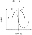
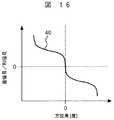
広角化の1手法であるモノパルス方式は、複数の受信アンテナを用い、各々の受信信号間の振幅差又は位相差により障害物等の対象物(以下単に「対象物」という)の方位を検出するものである。例えば、図14のように、ターゲット車両19から反射波33が2つの受信アンテナ34で受信され、まず、ハイブリッド回路35にて和信号36と差信号37が生成される。図15は和信号の方位角特性38、差信号の方位角特性39を示し、図16は和信号と差信号の比の方位角特性40を示す。図16において、和信号と差信号の比40は方位角について単調減少関数になるので、和信号と差信号の比40から一義的に方位角を決定することができる。また、対象物を特定できる方位範囲であれば、広範囲に渡る複数ターゲットも同時に高精度検知することができるので、システムの応答性に優れている。
The monopulse method, which is one method for widening the angle, uses a plurality of receiving antennas to detect the direction of an object such as an obstacle (hereinafter simply referred to as “object”) based on the amplitude difference or phase difference between the received signals. Is. For example, as shown in FIG. 14, the
モノパルス方式以外の方位検出方式には、単体では方位特定が不可であるビームを用い、同ビームを方向毎に複数用意し、それら複数のビームを切り替えるビームスイッチ方式がある。その他に、1本の同ビームをモータによって機械的に振る機械走査方式がある。ビームスイッチ方式はビーム数拡大による大型化、高コスト化の問題があるため、検知範囲の広角化には不向きである。また、両者ともビームの鋭さで方位分解能が決まると共に、ビームを鋭くするほどアンテナ面積が大になるため、高い分解能を実現するにはアンテナ面積の大型化は避けられない。 As an azimuth detection method other than the monopulse method, there is a beam switch method that uses a beam whose orientation cannot be specified by itself, prepares a plurality of the same beam for each direction, and switches between the plurality of beams. In addition, there is a mechanical scanning method in which one beam is mechanically shaken by a motor. The beam switch method is not suitable for widening the detection range because it has problems of increasing the size and cost by increasing the number of beams. In both cases, the azimuth resolution is determined by the sharpness of the beam, and the antenna area increases as the beam becomes sharper. Therefore, in order to achieve high resolution, the antenna area is inevitably increased.
図17は従来の広角レーダの説明図である。図17に示すように、ミリ波広角レーダ41は、移動体18前面に設置され、アンテナからメインローブbbによって送信信号がターゲット車両19に向かって放射される。ターゲット車両19で反射した信号を、メインローブbbとほぼ同じ範囲の検知角を持つ受信アンテナが受信し、送信信号との周波数差、位相差、時間差などからターゲット車両19までの速度と距離が求められる。
FIG. 17 is an explanatory diagram of a conventional wide-angle radar. As shown in FIG. 17, the millimeter-wave wide-
このようなミリ波広角レーダは、移動体18が停止しているときはノイズが小さく、良好な検知性能を持つ。しかし、移動体18が走行しているとき、例えば、矢印方向に移動速度Vmで走行しているとき、近傍にあるガードレール等の路側物体20が相対速度を持つため、反射信号は位置Aから位置Bの大きな散乱断面積を持つ障害物からの信号として受信される。モノパルス方式では、メインローブbbによってターゲット車両19と路側物体20からの信号が同時に受信されるため、ターゲット車両19の信号が路側物体20の信号に埋もれ、検知距離劣化や誤検知等の問題を引き起こしていた。
Such a millimeter-wave wide-angle radar has low noise when the moving
図17の走行状況において、上記路側物体によるミリ波広角レーダ受信信号のSN比劣化について説明する。位置A及び位置Bの、移動体18に搭載したレーダ41から見た位置A,B方向(それぞれ角度θ2a、角度θ2b)のそれぞれの相対速度成分V2a,V2bは、次の式(1)及び式(2)
V2a=Vmcosθ2a ・・・(1)
V2b=Vmcosθ2b ・・・(2)
となる。
In the traveling state of FIG. 17, the SN ratio deterioration of the millimeter-wave wide-angle radar received signal due to the roadside object will be described. The relative velocity components V2a and V2b of the positions A and B in the positions A and B (angle θ2a and angle θ2b, respectively) viewed from the
V2a = Vmcos θ2a (1)
V2b = Vmcos θ2b (2)
It becomes.
一方、ターゲット車両19の、レーダ41から見たターゲット方向(角度θ1)の相対速度成分Vtcは、ターゲット車両19の速度がVtであるとして、次の式(3)
Vtc=(Vt−Vm)cosθ1 ・・・(3)
で表される。
On the other hand, the relative speed component Vtc of the
Vtc = (Vt−Vm) cos θ1 (3)
It is represented by
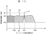
図18はモノパルス方式における、レーダで受信されたドップラー信号のスペクトル図である。横軸は反射波を介したターゲットの相対速度成分で、縦軸は受信信号強度である。レーダ搭載車が停止している場合のノイズレベルはNsで、レーダの電子回路部で発生するノイズ22によって決まっている。相対速度成分Vtcのターゲットからの受信信号21のレベルはStであるので、レーダ搭載車が停止している場合のSN比は(St−Ns)で表される。一方、レーダ搭載車が走行している場合は、相対速度成分V2aからV2bの範囲で路側物体からの信号23が急激に上昇する。これは、レーダ搭載車走行中は路側物体が相対速度を持つため、反射波を信号として受信してしまうからである。また、広角ビーム化は、メインローブより外側のサイドローブの上昇が不可避であるため、サイドローブによって相対速度成分0からV2aの範囲のノイズ42が上昇するという悪影響も存在する。従って、レーダ搭載車が走行している場合のSN比は(St−Nr)で表され、停止時に比べてSN比は劣化し、検知距離の減少や誤検知等の問題が起こる。
FIG. 18 is a spectrum diagram of a Doppler signal received by a radar in the monopulse system. The horizontal axis is the relative velocity component of the target via the reflected wave, and the vertical axis is the received signal intensity. The noise level when the radar-equipped vehicle is stopped is Ns, and is determined by the
モノパルス方式は、方位分解能に優れ、比較的小型での実現が可能である。しかし、上述のように、検知可能な方位範囲を拡大するにはアンテナビーム幅を広げる必要があり、検知可能な距離範囲が狭く、方位分解能も劣化してしまうという問題があった。 The monopulse method has excellent azimuth resolution and can be realized in a relatively small size. However, as described above, in order to expand the detectable azimuth range, it is necessary to widen the antenna beam width, and there is a problem that the detectable distance range is narrow and the azimuth resolution is degraded.
また、モノパルス方式以外の方位検出方式である機械走査方式は、ビーム方向を走査するので、時間的に対象物を分離することが可能である。しかし、走査範囲を広角化した場合には、システムに要求される応答時間を実現するために、モータ駆動部を高速化する必要があった。 In addition, since the mechanical scanning method, which is an azimuth detection method other than the monopulse method, scans the beam direction, it is possible to separate objects in terms of time. However, when the scanning range is widened, it is necessary to increase the speed of the motor drive unit in order to realize the response time required for the system.
特許文献2に記載された機械走査方式では、上記したように1次放射器を焦点に対して可動にすることにより、モノパルス方式の比較的狭い1個のビームを走査するので、全体として広角化され、装置の大型化を防ぐことができる。しかし、方向毎にビームの形状が変わるので、走査の都度補正が必要になり、更に、走査が連続して行なわれるので、走査途中の反射信号を用いて検出せざるを得なく、従って連続的に補正が必要になる。そのため、検出の信号処理の負荷が大きくなって信号処理が低速化し、広角化に必要不可欠なシステムの応答性に課題がある。
In the mechanical scanning method described in
方向毎にビームの形状が変わらないように、方向毎にモノパルス方式のアンテナを用意し、これら複数のアンテナを切り替えることにより、検知範囲を広角化する構造が本発明に先立ち考察された。この構成では、方向でビームの形状が変わらず、しかも静止しているアンテナを用いて検出が行なわれるので、信号処理に上記のような負荷が掛からず、信号処理が高速化される。また、上述の単体では方位特定が不可であるビームを切り替える方式に比べて、モノパルス方式のビームでは検知範囲内での方位特定が可能になるので、アンテナ数を格段に少なくすることができる。しかし、アンテナを複数用意する分、全体が大型になるのは避けられない。 Prior to the present invention, a structure that widens the detection range by preparing a monopulse antenna for each direction so that the beam shape does not change for each direction and switching the plurality of antennas was considered prior to the present invention. In this configuration, since the shape of the beam does not change depending on the direction and detection is performed using a stationary antenna, the above-described load is not applied to the signal processing, and the signal processing is speeded up. In addition, compared to the above-described method of switching the beam, which cannot specify the azimuth, the monopulse beam can specify the azimuth within the detection range, so that the number of antennas can be significantly reduced. However, it is inevitable that the size of the entire antenna will increase due to the provision of multiple antennas.
本発明の目的は、広い角度範囲での対象物検知に対して高速の信号処理が可能な車載用レーダを提供することにある。 An object of the present invention is to provide an in-vehicle radar capable of high-speed signal processing for object detection in a wide angle range.
上記目的を達成するための車載用レーダは、電磁波を放射する送信アンテナと、対象物によって反射された上記電磁波を受信する少なくとも2個の受信アンテナと、上記送信アンテナと上記少なくとも2個の受信アンテナとが配置されたアンテナ板と、上記少なくとも2個の受信アンテナが並ぶ方向を方位方向としたときに、上記方位方向に上記アンテナ板を回転することによって上記少なくとも2個の受信アンテナにより形成される検知角を走査する駆動部であって、走査と走査の間に回転を停止する静止時間を設ける駆動部と、上記少なくとも2個の受信アンテナから出力される受信信号と静止中の上記アンテナ板の回転角とから、上記静止時間において対象物の基準方向に対する方位角を検出する信号処理部とを具備して成ることを特徴とする。 In order to achieve the above object, a vehicle-mounted radar includes a transmission antenna that radiates electromagnetic waves, at least two reception antennas that receive the electromagnetic waves reflected by an object, the transmission antennas, and the at least two reception antennas. The antenna plate is formed by the at least two receiving antennas by rotating the antenna plate in the azimuth direction, where the direction in which the antenna plate is arranged and the direction in which the at least two receiving antennas are arranged is the azimuth direction. A driving unit that scans a detection angle, and includes a driving unit that provides a stationary time for stopping rotation between scannings, a reception signal output from the at least two receiving antennas, and a stationary antenna plate. And a signal processing unit that detects an azimuth angle with respect to the reference direction of the object in the stationary time from the rotation angle. To.
上記構成の本発明の車載用レーダは、狭い検知角を走査して広角度の検知を行なう。それにより、検知角外からの信号を排除することができ、例えば、左右路側物体と道路上ターゲットを時間的に分離することができる。その際、送受信アンテナを搭載した一台のアンテナを回転させるので、方向によってビーム形状は変わらず、かつ、走査の途中に静止時間が設けられ、その静止時間に信号処理が行なわれるため、信号処理の際の補正が不要となる。従って、広い角度範囲での対象物検知に対して高速の信号処理が可能になる。また、アンテナは、上記のように1組の送受信アンテナを搭載した1台で良いので、装置の大型化が避けられる。 The on-vehicle radar of the present invention configured as described above performs a wide angle detection by scanning a narrow detection angle. Thereby, signals from outside the detection angle can be eliminated, and for example, the left and right roadside objects and the road target can be separated in time. At that time, since one antenna equipped with a transmission / reception antenna is rotated, the beam shape does not change depending on the direction, and a stationary time is provided in the middle of scanning, and signal processing is performed during the stationary time. The correction at the time is not necessary. Therefore, high-speed signal processing is possible for object detection in a wide angle range. Further, as described above, one antenna having a set of transmission / reception antennas may be used as described above, so that an increase in size of the apparatus can be avoided.
本発明によれば、狭い検知角を走査して広角度検知を行なう際に、一台のアンテナ回転で走査が行なわれ、かつ、走査の途中に静止時間が設けられるので、信号処理の際の補正が不要となり、従って、広い角度範囲での対象物検知に対して高速の信号処理が可能になる。 According to the present invention, when performing a wide angle detection by scanning a narrow detection angle, the scan is performed by rotating one antenna, and a stationary time is provided in the middle of the scan. Correction is unnecessary, and therefore high-speed signal processing is possible for object detection in a wide angle range.
以下、本発明に係る車載用レーダを図面に示した幾つかの実施形態を参照して更に詳細に説明する。なお、実施形態を説明するための全図において、同一の符号は、同一物又は類似物を表示するものとする。 Hereinafter, the in-vehicle radar according to the present invention will be described in more detail with reference to some embodiments shown in the drawings. In all the drawings for explaining the embodiments, the same reference numerals indicate the same or similar items.
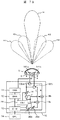
図1は、本発明の第1の実施形態を示す構成図である。送信アレイアンテナ(送信アンテナ)1及び受信アレイアンテナ(受信アンテナ)2a,2bは、アンテナプレート(アンテナ板)3上に配置される。発振器7で生成されたミリ波信号は、電力増幅器6を経て送信アレイアンテナ1に供給される。送信アレイアンテナ1から電磁波として放射された送信信号は、対象物(図示せず)で反射され、受信アレイアンテナ2a及び受信アレイアンテナ2bで受信され、それぞれから受信信号L,Rが出力される。受信信号L,Rは、それぞれミキサ8a,8bに加えられ、発振器7の出力信号と混合され、中間周波信号に変換される。中間周波信号は、低雑音増幅器9a,9bで増幅され、信号処理回路(DTM)13に入力される。
FIG. 1 is a configuration diagram showing a first embodiment of the present invention. The transmission array antenna (transmission antenna) 1 and the reception array antennas (reception antennas) 2 a and 2 b are arranged on an antenna plate (antenna plate) 3. The millimeter wave signal generated by the
方位角モータ4は、アンテナプレート3を方位角モータ4の位置を軸に方位方向に、所定の角度範囲(図1では約80度)内で回転させ、モノパルス方式によって対象物方位を特定するアンテナの検知角がna→nb→nc→nb→na→nd→ne→nd→naとなるように検知角を走査する。図1において、レーダ検知角はθr、アンテナ検知角はθmと示される。
The
モータドライバ(DRA)11は、方位角モータ4を制御し、アンテナプレート3を検知角na〜neのそれぞれの位置で一時的に静止させる。この静止時間は信号処理回路13の処理能力によって定められる。アンテナ角度モニタ(MRA)12は、アンテナプレート3の回転角、即ち方位角情報をモニタし、信号処理回路13へ出力する。方位角情報は、基準方向(図1において、検知角naの方向、レーダを移動体に搭載したときは、移動体の走行方向)からの回転の角度である。
The motor driver (DRA) 11 controls the
アンテナプレート3が静止している状態において、信号処理回路13は、受信信号の周波数変換された信号と、アンテナプレート3の方位角情報を用いて対象物の方位角を検出する。また、同時に対象物のレーダ搭載車との相対的な速度、距離などを検出する。これらの検出結果は必要に応じて、表示装置(DPL)14などの出力装置に適した信号に変換され、出力装置に出力される。また、電力増幅器6、発振器7、ミキサ8a,8b、低雑音増幅器9a,9b、モータドライバ11、アンテナ角度モニタ12及び信号処理回路13を含んで送受信装置10が構成される。
In a state where the
また、送信アレイアンテナ1、受信アレイアンテナ2a、2bはドーム形状をした、誘電体から成るレドーム5に覆われている。レドーム5は、回転せず固定しており、前面と送受信アンテナとの距離が走査が行なわれたときにほぼ一定となるように、前面が湾曲している。この形状により、走査によってビーム形状が殆ど変化せず、ビーム形状をほぼ一定に維持することができる。なお、レドームを、送受信アンテナの全面に同じ厚さで形成することが可能である。アンテナプレート3にレドームが固定される分、回転部の重量が増すが、ビーム形状はどの走査位置でも同一となる。
The transmitting
図2は本実施形態に用いるアンテナの上方図である。複数のパッチ素子15と給電配線16が誘電体基板上に構成され、送信アレイアンテナ1、受信アレイアンテナ2a,2bをそれぞれ成している。各アレイアンテナは、アンテナプレート3上に配置される。本実施形態のアンテナは平面型であるため、レーダの薄型化を実現することができる。
FIG. 2 is an upper view of the antenna used in this embodiment. A plurality of
本実施形態の効果について図3〜図6を用いて説明する。図3では、本レーダ17が移動体18の前面に設置され、ある時間においてアンテナの検知角ndでターゲット車両19を検知している。図4はこの状態におけるドップラー信号のスペクトル図である。相対速度成分Vtcのターゲット19からの受信信号21のレベルはStである。また、路側物体20からの信号は検知されないので、ノイズレベルNrはレーダの電子回路部で発生するノイズ22によって決まる。従って、SN比は(St−Nr)で表される。
The effect of this embodiment will be described with reference to FIGS. In FIG. 3, the
一方、図5では、ある時間においてアンテナの検知角ncで路側物体20を検知している。図6はこの状態におけるドップラー信号のスペクトル図である。路側物体からの受信信号23は相対速度成分V2aからV2bの範囲で広がりを持っており、信号レベルはSeである。また、狭いアンテナ検知角を用いているので、メインローブより外側のサイドローブを低減することができ、相対速度成分0からV2aの範囲のノイズ上昇を防止することができる。ターゲット車両19からの信号は検知されないので、ノイズレベルNrはレーダの電子回路部で発生するノイズ22によって決まる。従って、SN比は(Se−Nr)で表される。
On the other hand, in FIG. 5, the
以上により、本実施形態の車載レーダは、狭い検知角を走査して広角度の検知を行なう。それにより、検知角外からの信号を排除することができ、例えば、左右路側物体と道路上ターゲットを時間的に分離することができる。その際、送受信アンテナを搭載した一台のアンテナを回転させるので、方向によってビーム形状は変わらず、かつ、走査の途中に静止時間が設けられ、その静止時間に信号処理が行なわれるため、信号処理の際の補正が不要となる。従って、広い角度範囲での対象物検知に対して高速の信号処理が可能になる。また、アンテナは、上記のように1組の送受信アンテナを搭載した1台で良いので、装置の大型化が避けられる。なお、走査の対象が、対象物方位をモノパルス方式で特定するアンテナ検知角であるため、従来の機械走査方式の一例である、方位特定が不可である1つのビームを走査する例と比較すると、より走査範囲を狭くすることができ、応答性の向上が可能になる。更に、従来の広い検知角にして走査を行なわない例と比べると、受信アンテナ単体は狭い検知角で足りるので、距離精度、方位精度を改善することができる。 As described above, the on-vehicle radar according to the present embodiment scans a narrow detection angle and detects a wide angle. Thereby, signals from outside the detection angle can be eliminated, and for example, the left and right roadside objects and the road target can be separated in time. At that time, since one antenna equipped with a transmission / reception antenna is rotated, the beam shape does not change depending on the direction, and a stationary time is provided in the middle of scanning, and signal processing is performed during the stationary time. The correction at the time is not necessary. Therefore, high-speed signal processing is possible for object detection in a wide angle range. Further, as described above, one antenna having a set of transmission / reception antennas may be used as described above, so that an increase in size of the apparatus can be avoided. Since the object to be scanned is an antenna detection angle that specifies the object direction in a monopulse method, compared to an example of scanning a single beam that cannot be specified as an example of a conventional mechanical scanning method, The scanning range can be further narrowed, and responsiveness can be improved. Furthermore, compared with the conventional example in which scanning is not performed with a wide detection angle, a narrow detection angle is sufficient for the receiving antenna alone, so that the distance accuracy and the azimuth accuracy can be improved.
本実施形態ではパッチアンテナを用いているが、スロットアンテナやトリプレートアンテナのような、同様の平面アンテナを用いることが可能であり、同じようにレーダの薄型化を実現することができる。また、サーキュレータを用いて送信アンテナと受信アンテナを共用にすることが可能である。それにより、レーダの省面積化が可能になる。更に、送受信装置10のうち、ミリ波信号を取り扱う部品である電力増幅器6、発振器7、ミキサ8a,8b、低雑音増幅器9a,9bをアンテナプレート3裏面に配置すればミリ波信号を低損失で伝送することができる。また、逆に受信アレイアンテナ2a、2bのみを回転させることで、方位角モータ4が低トルクであっても高速走査することが可能になる。
Although the patch antenna is used in this embodiment, a similar planar antenna such as a slot antenna or a triplate antenna can be used, and the radar can be thinned in the same manner. Moreover, it is possible to share a transmission antenna and a reception antenna using a circulator. As a result, the area of the radar can be reduced. Furthermore, if the
レーダ検知角θrを維持しつつ、アンテナ検知角θmを大きくすれば、アンテナプレート3の全回転角を小さくできるので、高速走査が可能になる。逆にアンテナ検知角θmを小さくすれば、更に距離精度、方位精度を向上することができる。また、アンテナの検知角同士が重複するように、アンテナ検知角θm及び静止位置を選択すれば、対象物情報の精度が上がり、誤検知を防止することが可能になる。
If the antenna detection angle θm is increased while maintaining the radar detection angle θr, the total rotation angle of the
また、本実施形態はレーダ搭載車の速度、対象物との相対速度、車間距離等の走行環境に応じて、機械走査範囲を切り替えることにより、運転者が必要としている最適な情報を提供することができる。具体的には、例えばレーダ搭載車の速度が速いときには前方の対象物の検出が特に重要となり、移動体近傍からの不要な反射波等の防止を行なう必要があるため、機械走査範囲を狭めることが有効である。若しくは、レーダ搭載車正面のアンテナ検知角同士のピッチを狭くする等、レーダ搭載車正面を重点的に走査することが有効である。一方、移動体の速度が遅いときには移動体近傍の対象物の検出を行なう必要があるため、機械走査範囲を広くすることが有効である。若しくは、レーダ搭載車正面のアンテナ検知角同士のピッチを広げる等、広範囲に走査することが有効である。レーダ搭載車と対象物との相対速度や車間距離についても同様である。更にレーダ搭載車のハンドル等と連動させて機械走査範囲を切り替えることもできる。 In addition, the present embodiment provides the optimum information required by the driver by switching the mechanical scanning range according to the traveling environment such as the speed of the radar-equipped vehicle, the relative speed with respect to the object, and the inter-vehicle distance. Can do. Specifically, for example, when the speed of a radar-equipped vehicle is high, detection of an object ahead is particularly important, and it is necessary to prevent unnecessary reflected waves from the vicinity of the moving body, so that the mechanical scanning range is narrowed. Is effective. Alternatively, it is effective to focus on the front of the radar-equipped vehicle, such as narrowing the pitch between the antenna detection angles on the front of the radar-equipped vehicle. On the other hand, since it is necessary to detect an object near the moving body when the speed of the moving body is slow, it is effective to widen the mechanical scanning range. Alternatively, it is effective to scan over a wide range, such as widening the pitch between the antenna detection angles in front of the radar-equipped vehicle. The same applies to the relative speed between the radar-equipped vehicle and the object and the inter-vehicle distance. Further, the mechanical scanning range can be switched in conjunction with the handle of a radar-equipped vehicle.
図7Aは本発明の第2の実施形態を示す構成図である。本実施形態では、アンテナの検知角naのときの検知距離を制御する検知距離制御部(CNT)24が第1の実施形態に追加して備えられる。送信アレイアンテナ1、受信アレイアンテナ2a、2bはアンテナプレート3上に配置される。発振器7で生成されたミリ波信号は可変利得増幅器25を経て送信アレイアンテナ1に加えられる。送信アレイアンテナ1から放射された送信信号は、対象物で反射され、受信アレイアンテナ2a及び受信アレイアンテナ2bで受信される。受信信号L、Rは、それぞれミキサ8a及び8bに加えられ発振器7の出力信号と混合され、中間周波信号に変換され、低雑音可変利得増幅器26a及び26bで増幅され、信号処理回路13に入力される。方位角モータ4は、アンテナプレート3を回転させ、モノパルス方式によって対象物方位を特定するアンテナの検知角をna→nb→nc→nb→na→nd→ne→nd→naと走査することができる。モータドライバ11は、方位角モータ4を制御し、アンテナプレート3を検知角na〜neのそれぞれで一時的に静止させる。この静止時間は信号処理回路の処理能力による。アンテナ角度モニタ12は、アンテナプレート3の回転角、即ち方位角情報をモニタし、信号処理回路13へ出力する。
FIG. 7A is a block diagram showing a second embodiment of the present invention. In the present embodiment, a detection distance control unit (CNT) 24 that controls the detection distance at the detection angle na of the antenna is provided in addition to the first embodiment. The
アンテナプレート3が静止している状態において、信号処理回路13は、受信信号の周波数変換された信号と、アンテナプレート3の方位角情報を用いて対象物の方位角を検出する。同時に、対象物のレーダ搭載車との相対的な速度、距離などを検出する。これらの検出結果は必要に応じて、表示装置14などの出力装置に適した信号に変換され、出力装置に出力される。
In a state where the
また、検知距離制御部(CNT)24は、アンテナ角度モニタ12から命令信号を受け、検知角naのときは、検知角nb〜neのときに比べ、可変利得増幅器25又は低雑音可変利得増幅器26a,26bの少なくとも一方の利得を大きくする。これにより、遠距離対象物の検知が可能になる。また、送信アレイアンテナ1、受信アレイアンテナ2a、2bはドーム形状をした、誘電体から成るレドーム5に覆われている。
The detection distance control unit (CNT) 24 receives a command signal from the antenna angle monitor 12, and at the detection angle na, the
本実施形態では、正面の検知角naにおいて、他の検知角nb〜neと比べ、遠距離対象物の検知が可能となるので、狭角/長距離、広角/近距離の二つの機能を統合した一個のレーダを低コストで実現することができる。また、第1の実施形態の場合と同様に、本実施形態の車載レーダは、狭い検知角を走査して広角度の検知を行なう。それにより、検知角外からの信号を排除することができ、例えば、左右路側物体と道路上ターゲットを時間的に分離することができる。その際、送受信アンテナを搭載した一台のアンテナを回転させるので、方向によってビーム形状は変わらず、かつ、走査の途中に静止時間が設けられ、その静止時間に信号処理が行なわれるため、信号処理の際の補正が不要となる。従って、広い角度範囲での対象物検知に対して高速の信号処理が可能になる。また、アンテナは、上記のように1組の送受信アンテナを搭載した1台で良いので、装置の大型化が避けられる。なお、走査の対象が、対象物方位をモノパルス方式で特定するアンテナ検知角であるため、従来の機械走査方式の一例である、方位特定が不可である1つのビームを走査する例と比較すると、より走査範囲を狭くすることができ、応答性の向上が可能になる。更に、従来の広い検知角にして走査を行なわない例と比べると、受信アンテナ単体は狭い検知角で足りるので、距離精度、方位精度を改善することができる。 In the present embodiment, since it is possible to detect a long-distance object at the front detection angle na compared to the other detection angles nb to ne, two functions of narrow angle / long distance and wide angle / short distance are integrated. This single radar can be realized at low cost. Similarly to the case of the first embodiment, the on-vehicle radar according to the present embodiment scans a narrow detection angle and detects a wide angle. Thereby, signals from outside the detection angle can be eliminated, and for example, the left and right roadside objects and the road target can be separated in time. At that time, since one antenna equipped with a transmission / reception antenna is rotated, the beam shape does not change depending on the direction, and a stationary time is provided in the middle of scanning, and signal processing is performed during the stationary time. The correction at the time is not necessary. Therefore, high-speed signal processing is possible for object detection in a wide angle range. Further, as described above, one antenna having a set of transmission / reception antennas may be used as described above, so that an increase in size of the apparatus can be avoided. Since the object to be scanned is an antenna detection angle that specifies the object direction in a monopulse method, compared to an example of scanning a single beam that cannot be specified as an example of a conventional mechanical scanning method, The scanning range can be further narrowed, and responsiveness can be improved. Furthermore, compared with the conventional example in which scanning is not performed with a wide detection angle, a narrow detection angle is sufficient for the receiving antenna alone, so that the distance accuracy and the azimuth accuracy can be improved.
なお、図7Bに本実施形態でサーキュレータを用いて送信アンテナと受信アンテナを共用にする場合の構成を示す。図7Bにおいて、101a,101bは送受信共用アンテナ、102a,102bは共用アンテナ101a,101bのそれぞれに接続されたサーキュレータである。サーキュレータ102a,102bによって送受信の切替が行なわれる。このようにアンテナを共用にすることにより、レーダの省面積化が可能になる。送受信アンテナ共用の構成は、他の実施形態でも同様である。
FIG. 7B shows a configuration when the transmitting antenna and the receiving antenna are shared using a circulator in this embodiment. In FIG. 7B, 101a and 101b are transmission / reception shared antennas, and 102a and 102b are circulators connected to the shared
図8は本実施形態の応用についての説明図である。自動車の一層の安全性向上のため、1台の車両に複数のレーダを搭載することが将来的に考えられる。一般的な構想では、車両正面にはACC(自動追従)用の狭角/長距離レーダ、衝突感知用の広角/近距離レーダは車両正面、側面及び後方に搭載されると考えられている。しかし、この複数レーダ搭載は高価となるので、低コスト化のため、狭角/長距離、広角/近距離の機能を統合したレーダが望まれる。図8に示した応用はこのような観点から成されたものである。本レーダ27は移動体18前面に設置され、移動体正面は長距離で、斜め方向は近距離の検知範囲となっている。また、従来の広角レーダであるサイドセンサ28a,28bが移動体18側面に設置され、広角/近距離の検知範囲bx、byを有している。更に、移動体18後方にはリアセンサ29が設置されており、同様に広い広角/近距離の検知範囲bzを有している。以上により、必要最小限のレーダ個数で移動体周辺を360度検知することができ、安全性に優れたレーダシステムを低コストで実現することができる。
FIG. 8 is an explanatory diagram for the application of this embodiment. In order to further improve the safety of automobiles, it is conceivable in the future to mount a plurality of radars on one vehicle. In a general concept, it is considered that a narrow-angle / long-range radar for ACC (automatic tracking) and a wide-angle / short-range radar for collision detection are mounted on the front, side and rear of the vehicle. However, since this multiple radar mounting is expensive, a radar that integrates the functions of narrow angle / long distance and wide angle / short distance is desired for cost reduction. The application shown in FIG. 8 is made from such a viewpoint. The
図9は本発明の第3の実施形態を表す構成図である。本実施形態では、アンテナを仰角(道路面に垂直な方向の角度)方向に回転する仰角モータ30が第1の実施形態に追加して備えられる。送信アレイアンテナ1、受信アレイアンテナ2a、2bはアンテナプレート3上に配置される。発振器7で生成されたミリ波信号は電力増幅器6を経て送信アレイアンテナ1に加えられる。送信アレイアンテナ1から放射された送信信号は、対象物で反射され、受信アレイアンテナ2a及び受信アレイアンテナ2bで受信される。受信信号L、Rはそれぞれミキサ8a及び8bに加えられ発振器7の出力信号と混合され、中間周波信号に変換され、低雑音増幅器9a及び9bで増幅され、信号処理回路13に入力される。方位角モータ4は、アンテナプレート3を回転させ、モノパルス方式によって対象物方位を特定するアンテナの検知角をna→nb→nc→nb→na→nd→ne→nd→naと走査することができる。
FIG. 9 is a block diagram showing a third embodiment of the present invention. In this embodiment, an
仰角モータ30は、アンテナプレート3を仰角方向に回転させる。モータドライバ11は、方位角モータ4、仰角モータ30を制御し、アンテナプレート3の方位方向及び仰角方向の回転を一時停止させる。この静止時間は、信号処理回路の処理能力によって設定され、方位方向と仰角方向の走査の両者が停止しているときに信号処理が行なわれる。
The
アンテナ角度モニタ12は、アンテナプレート3の方位角及び仰角をモニタし、信号処理回路13へ出力する。アンテナプレート3が静止している状態において、信号処理回路13は、受信信号の周波数変換された信号と、アンテナプレート3の方位角、仰角情報を用いて対象物の位置を検出する。また、同時に対象物のレーダ搭載車との相対的な速度、距離などを検出する。これらの検出結果は必要に応じて、表示装置14などの出力装置に適した信号に変換され、出力装置に出力される。また、送信アレイアンテナ1、受信アレイアンテナ2a、2bはドーム形状をした、誘電体を含んで成るレドーム5に覆われている。
The antenna angle monitor 12 monitors the azimuth and elevation angles of the
図10は本実施形態の仰角方向の走査についての説明図である。本レーダ31は移動体18前面に設置される。仰角モータ30はアンテナプレート3を回転させ、モノパルス方式によって対象物方位を特定するアンテナの検知角をea→eb→ec→eb→ea→ed→eaと走査する。
FIG. 10 is an explanatory diagram for scanning in the elevation angle direction of the present embodiment. The
従って、本実施形態によれば、高さ方向の対象物の簡単な分離が可能になり、トンネルや鉄橋などを認識することができる。また、起伏の激しい道路を走行しているときでも対象物を見落とさずに検出することができる。 Therefore, according to this embodiment, the object in the height direction can be easily separated, and a tunnel, an iron bridge, or the like can be recognized. Further, even when the vehicle is traveling on a rough road, the object can be detected without overlooking it.
第1の実施形態の場合と同様に、本実施形態の車載レーダは、狭い検知角を走査して広角度の検知を行なう。それにより、検知角外からの信号を排除することができ、例えば、左右路側物体と道路上ターゲットを時間的に分離することができる。その際、送受信アンテナを搭載した一台のアンテナを回転させるので、方向によってビーム形状は変わらず、かつ、走査の途中に静止時間が設けられ、その静止時間に信号処理が行なわれるため、信号処理の際の補正が不要となる。従って、広い角度範囲での対象物検知に対して高速の信号処理が可能になる。また、アンテナは、上記のように1組の送受信アンテナを搭載した1台で良いので、装置の大型化が避けられる。なお、走査の対象が、対象物方位をモノパルス方式で特定するアンテナ検知角であるため、従来の機械走査方式の一例である、方位特定が不可である1つのビームを走査する例と比較すると、より走査範囲を狭くすることができ、応答性の向上が可能になる。更に、従来の広い検知角にして走査を行なわない例と比べると、受信アンテナ単体は狭い検知角で足りるので、距離精度、方位精度を改善することができる。 As in the case of the first embodiment, the on-vehicle radar according to the present embodiment scans a narrow detection angle and detects a wide angle. Thereby, signals from outside the detection angle can be eliminated, and for example, the left and right roadside objects and the road target can be separated in time. At that time, since one antenna equipped with a transmission / reception antenna is rotated, the beam shape does not change depending on the direction, and a stationary time is provided in the middle of scanning, and signal processing is performed during the stationary time. The correction at the time is not necessary. Therefore, high-speed signal processing is possible for object detection in a wide angle range. Further, as described above, one antenna having a set of transmission / reception antennas may be used as described above, so that an increase in size of the apparatus can be avoided. Since the object to be scanned is an antenna detection angle that specifies the object direction in a monopulse method, compared to an example of scanning a single beam that cannot be specified as an example of a conventional mechanical scanning method, The scanning range can be further narrowed, and responsiveness can be improved. Furthermore, compared with the conventional example in which scanning is not performed with a wide detection angle, a narrow detection angle is sufficient for the receiving antenna alone, so that the distance accuracy and the azimuth accuracy can be improved.
なお、車載用レーダの使用目的によっては、仰角方向の検知を重視し、方位方向の走査が可能となる場合がある。そのような目的のための車載用レーダでは、方位角モータ4が省略される。
Depending on the purpose of use of the on-vehicle radar, emphasis is placed on the detection in the elevation direction, and scanning in the azimuth direction may be possible. In the in-vehicle radar for such a purpose, the
図11は本発明の第4の実施形態を示す構成図である。本実施形態では、受信アレイアンテナ2c,2dとそれらに接続される諸回路が第3の実施形態に追加して備えられる。送信アレイアンテナ1、受信アレイアンテナ2a〜2dは、アンテナプレート3上に配置される。発振器7で生成されたミリ波信号は電力増幅器6を経て送信アレイアンテナ1に加えられる。送信アレイアンテナ1から放射された送信信号は、対象物で反射され、受信アレイアンテナ2a〜2dで受信される。受信アレイアンテナ2a〜2dから受信信号TL,TR,BL,BRがそれぞれ出力される。受信信号TL,TR,BL,BRは、それぞれミキサ8a〜8dに加えられ、発振器7の出力信号と混合され、中間周波信号に変換され、低雑音増幅器9a〜9dで増幅され、信号処理回路13に入力される。
FIG. 11 is a block diagram showing a fourth embodiment of the present invention. In the present embodiment, the receiving
ここで、図12に本実施形態に用いるアンテナの上方図を示す。複数のパッチ素子15と給電配線16が誘電体基板上に構成され、送信アレイアンテナ1、受信アレイアンテナ2a〜2dをそれぞれ成している。4個の受信アンテナ2a〜2dの各々は、互いに水平方向及び垂直方向で隣接して配置されている。更に、各種アレイアンテナはアンテナプレート3上に配置される。本実施形態のアンテナは平面型であるため、レーダの薄型化を実現することができる。
Here, FIG. 12 shows an upper view of the antenna used in this embodiment. A plurality of
アンテナプレート3の正面の方向を基準とした対象物の方位角は、図12において横方向になるアンテナ2a,2bからの受信信号TL,TRの振幅差又は位相差によって特定することができる。もちろん、受信信号BL,BRの比較、或いは受信信号の和(TL+BL),(TR+BR)の比較でも対象物の方位角を特定することが可能である。また、アンテナプレート3の正面の方向を基準とした対象物の仰角は、図12において縦方向になるアンテナ2a,2cからの受信信号TL,BLの振幅差又は位相差によって特定することができる。同様に、受信信号TR,BRの比較、或いは受信信号の和(TL+TR),(BL+BR)の比較でも対象物の仰角を特定することが可能である。
The azimuth angle of the object relative to the front direction of the
方位角モータ4は、アンテナプレート3を回転させ、モノパルス方式によって対象物方位を特定するアンテナの検知角をna→nb→nc→nb→na→nd→ne→nd→naと走査する。また、仰角モータ30は、アンテナプレート3を仰角方向に回転させる。モータドライバ11は、方位角モータ4及び仰角モータ30を制御し、アンテナプレート3をそれぞれのアンテナ方位角で一時的に静止させる。この静止時間は信号処理回路の処理能力による。
The
アンテナ角度モニタ12は、アンテナプレート3の方位角、仰角をモニタし、信号処理回路13へ出力する。アンテナプレート3が静止している状態において、信号処理回路13は受信信号の周波数変換された信号と、アンテナプレート3の方位角、仰角情報を用いて対象物の位置を検出する。また、同時に対象物のレーダ搭載車との相対的な速度、距離などを検出する。これらの検出結果は必要に応じて、表示装置14などの出力装置に適した信号に変換され、出力装置に出力される。また、送信アレイアンテナ1、受信アレイアンテナ2a、2bはドーム形状をした、誘電体から成るレドーム5に覆われている。
The antenna angle monitor 12 monitors the azimuth and elevation angles of the
図13は本実施形態の仰角方向の走査についての説明図である。本レーダ32は移動体18前面に設置される。仰角モータはアンテナプレートを回転させ、モノパルス方式によって対象物の方位角と仰角を特定するアンテナの検知角をfa→fb→fc→fb→fa→fd→faと走査する。従って、本実施形態によれば、高さ方向の対象物を正確に分離することが可能になり、トンネルや鉄橋などを認識することができる。また、起伏の激しい道路を走行しているときでも対象物を見落とさずに検出することができる。
FIG. 13 is an explanatory diagram for scanning in the elevation direction of the present embodiment. The
本実施形態の車載レーダは、第3の実施形態の場合と同様に、狭い検知角を走査して広角度の検知を行なう。それにより、検知角外からの信号を排除することができ、例えば、左右路側物体と道路上ターゲットを時間的に分離することができる。その際、送受信アンテナを搭載した一台のアンテナを回転させるので、方向によってビーム形状は変わらず、かつ、走査の途中に静止時間が設けられ、その静止時間に信号処理が行なわれるため、信号処理の際の補正が不要となる。従って、広い角度範囲での対象物検知に対して高速の信号処理が可能になる。また、アンテナは、上記のように1組の送受信アンテナを搭載した1台で良いので、装置の大型化が避けられる。なお、走査の対象が、対象物方位をモノパルス方式で特定するアンテナ検知角であるため、従来の機械走査方式の一例である、方位特定が不可である1つのビームを走査する例と比較すると、より走査範囲を狭くすることができ、応答性の向上が可能になる。更に、従来の広い検知角にして走査を行なわない例と比べると、受信アンテナ単体は狭い検知角で足りるので、距離精度、方位精度を改善することができる。 As in the case of the third embodiment, the in-vehicle radar of this embodiment scans a narrow detection angle and detects a wide angle. Thereby, signals from outside the detection angle can be eliminated, and for example, the left and right roadside objects and the road target can be separated in time. At that time, since one antenna equipped with a transmission / reception antenna is rotated, the beam shape does not change depending on the direction, and a stationary time is provided in the middle of scanning, and signal processing is performed during the stationary time. The correction at the time is not necessary. Therefore, high-speed signal processing is possible for object detection in a wide angle range. Further, as described above, one antenna having a set of transmission / reception antennas may be used as described above, so that an increase in size of the apparatus can be avoided. Since the object to be scanned is an antenna detection angle that specifies the object direction in a monopulse method, compared to an example of scanning a single beam that cannot be specified as an example of a conventional mechanical scanning method, The scanning range can be further narrowed, and responsiveness can be improved. Furthermore, compared with the conventional example in which scanning is not performed with a wide detection angle, a narrow detection angle is sufficient for the receiving antenna alone, so that the distance accuracy and the azimuth accuracy can be improved.
なお、本実施形態ではパッチアンテナを用いているが、スロットアンテナやトリプレートアンテナのような、同じ平面アンテナを用いることが可能であり、同様にレーダの薄型化を実現することができる。 Although the patch antenna is used in this embodiment, the same planar antenna such as a slot antenna or a triplate antenna can be used, and the radar can be thinned in the same manner.
1…送信アレイアンテナ、2…受信アレイアンテナ、3…アンテナプレート、4…方位角モータ、5…レドーム、6…電力増幅器、7…発振器、8…ミキサ、9…低雑音増幅器、10…送受信装置、11…モータドライバ、12…アンテナ角度モニタ、13…信号処理回路、14…表示装置、15…パッチ素子、16…給電配線、17,27,31,32…本発明の車載用レーダ、18…移動体、19…ターゲット車両、20…路側物体、24…検知距離制御部、25…可変利得増幅器、26…低雑音可変利得増幅器、30…仰角モータ。
DESCRIPTION OF
Claims (17)
対象物によって反射された上記電磁波を受信する少なくとも2個の受信アンテナと、
上記送信アンテナと上記少なくとも2個の受信アンテナとが配置されたアンテナ板と、
上記少なくとも2個の受信アンテナが並ぶ方向を方位方向としたときに、上記方位方向に上記アンテナ板を回転することによって上記少なくとも2個の受信アンテナにより形成される検知角を走査する駆動部であって、走査と走査の間に回転を停止する静止時間を設ける駆動部と、
上記少なくとも2個の受信アンテナから出力される受信信号と静止中の上記アンテナ板の回転角とから、上記静止時間において基準方向に対する対象物の方位角を検出する信号処理部とを具備して成ることを特徴とする車載用レーダ。 A transmitting antenna that radiates electromagnetic waves;
At least two receiving antennas for receiving the electromagnetic wave reflected by the object;
An antenna plate on which the transmitting antenna and the at least two receiving antennas are disposed;
A drive unit that scans a detection angle formed by the at least two receiving antennas by rotating the antenna plate in the azimuth direction when the direction in which the at least two receiving antennas are arranged is an azimuth direction. A drive unit for providing a stationary time for stopping rotation between scans;
A signal processing unit for detecting an azimuth angle of an object with respect to a reference direction in the stationary time from reception signals output from the at least two receiving antennas and a rotation angle of the stationary antenna plate; In-vehicle radar characterized by the above.
上記少なくとも2個の受信アンテナから出力される受信信号の振幅差又は位相差を比較して上記方位角を検出することを特徴とする車載用レーダ。 In claim 1,
A vehicle-mounted radar, wherein the azimuth angle is detected by comparing amplitude differences or phase differences of reception signals output from the at least two reception antennas.
上記少なくとも2個の受信アンテナが送信アンテナを兼ねていることを特徴とする車載用レーダ。 In claim 1,
The on-vehicle radar, wherein the at least two receiving antennas also serve as transmitting antennas.
上記検知角を有して検知範囲が形成され、静止中の上記検知範囲とそれに続く次の走査の後の静止中の検知範囲とが互いに重複している部分を有していることを特徴とする車載用レーダ。 In claim 1,
A detection range is formed with the detection angle, and the detection range at rest and a detection range at rest after the next scan have portions overlapping each other. In-vehicle radar.
上記駆動部は、上記走査の範囲を異なる範囲に切り替えることを特徴とする車載用レーダ。 In claim 1,
The on-vehicle radar, wherein the driving unit switches the scanning range to a different range.
上記送信アンテナと上記少なくとも2個の受信アンテナとを覆うレドームを更に具備し、上記レドームは誘電体を含んで成り、上記レドームの上面が走査方向に湾曲していることを特徴とする車載用レーダ。 In claim 1,
A vehicle-mounted radar, further comprising a radome that covers the transmitting antenna and the at least two receiving antennas, the radome including a dielectric, and an upper surface of the radome being curved in a scanning direction. .
静止中の回転角に応じて、上記送信アンテナから発射される電磁波の強度が変化することを特徴とする車載用レーダ。 In claim 1,
A vehicle-mounted radar characterized in that the intensity of electromagnetic waves emitted from the transmitting antenna changes according to a stationary rotation angle.
上記信号処理部は、静止中の回転角に応じて、上記受信信号のレベルを変えて上記方位角を検出することを特徴とする車載用レーダ。 In claim 1,
The on-vehicle radar, wherein the signal processing unit detects the azimuth angle by changing a level of the reception signal according to a stationary rotation angle.
対象物によって反射された上記電磁波を受信する少なくとも2個の受信アンテナと、
上記送信アンテナと上記少なくとも2個の受信アンテナとが配置されたアンテナ板と、
上記少なくとも2個の受信アンテナが並ぶ方向を方位方向としたときに、上記方位方向とは垂直の仰角方向に上記アンテナ板を回転することによって上記少なくとも2個の受信アンテナにより形成される検知角を仰角方向に走査する駆動部であって、走査と走査の間に回転を停止する静止時間を設ける駆動部と、
上記少なくとも2個の受信アンテナから出力される受信信号から、上記静止時間において、対象物の基準方向に対する、静止中の仰角方向における方位角を検出する信号処理部とを具備して成ることを特徴とする車載用レーダ。 A transmitting antenna that radiates electromagnetic waves;
At least two receiving antennas for receiving the electromagnetic waves reflected by the object;
An antenna plate on which the transmitting antenna and the at least two receiving antennas are disposed;
When the direction in which the at least two receiving antennas are arranged is an azimuth direction, a detection angle formed by the at least two receiving antennas by rotating the antenna plate in an elevation angle direction perpendicular to the azimuth direction. A drive unit that scans in an elevation direction, the drive unit providing a stationary time for stopping rotation between scans; and
A signal processing unit configured to detect an azimuth angle in a stationary elevation direction with respect to a reference direction of an object in the stationary time from reception signals output from the at least two receiving antennas. In-vehicle radar.
上記駆動部は、上記少なくとも2個の受信アンテナが並ぶ方向を方位方向としたときに、上記方位方向に上記アンテナ板を回転して上記少なくとも2個の受信アンテナによる検知角を方位方向に走査し、上記静止時間に方位方向の走査を停止することを特徴とする車載用レーダ。 In claim 9,
The driving unit rotates the antenna plate in the azimuth direction and scans the detection angle by the at least two reception antennas in the azimuth direction when the direction in which the at least two reception antennas are arranged is the azimuth direction. An on-vehicle radar characterized by stopping scanning in the azimuth direction during the stationary time.
上記少なくとも2個の受信アンテナから出力される受信信号の振幅差又は位相差を比較して上記方位角を検出することを特徴とする車載用レーダ。 In claim 10,
A vehicle-mounted radar, wherein the azimuth angle is detected by comparing amplitude differences or phase differences of reception signals output from the at least two reception antennas.
上記少なくとも2個の受信アンテナが送信アンテナを兼ねていることを特徴とする車載用レーダ。 In claim 10,
The on-vehicle radar, wherein the at least two receiving antennas also serve as transmitting antennas.
上記検知角を有して検知範囲が形成され、静止中の上記検知範囲と、それに続く次の仰角方向及び方位方向の走査の後の静止中の検知範囲とが互いに重複している部分を有していることを特徴とする車載用レーダ。 In claim 10,
A detection range is formed with the detection angle, and there is a portion where the detection range at rest and the detection range at rest after scanning in the next elevation angle direction and azimuth direction overlap each other. In-vehicle radar.
対象物によって反射された上記電磁波を受信する少なくとも4個の受信アンテナであって、それらの各々が互いに水平方向及び垂直方向で隣接して配置されている少なくとも4個の受信アンテナと、
上記送信アンテナと上記少なくとも4個の受信アンテナとが配置されたアンテナ板と、
上記水平方向を方位方向としたときに、上記方位方向と上記方位方向に対して垂直の仰角方向とに上記アンテナ板を回転し、上記少なくとも4個の受信アンテナによって形成される検知角を方位方向及び仰角方向に走査する駆動部であって、走査と走査の間に回転を停止する静止時間を設ける駆動部と、
上記少なくとも4個の受信アンテナから出力される受信信号と、静止中の上記アンテナ板の方位方向及び仰角方向の回転角とから、上記静止時間において基準方向に対する対象物の方位角及び仰角を検出する信号処理部とを具備して成ることを特徴とする車載用レーダ。 A transmitting antenna that radiates electromagnetic waves;
At least four receiving antennas for receiving the electromagnetic waves reflected by the object, each of which is arranged adjacent to each other in the horizontal and vertical directions; and
An antenna plate on which the transmitting antenna and the at least four receiving antennas are disposed;
When the horizontal direction is the azimuth direction, the antenna plate is rotated in the azimuth direction and an elevation angle direction perpendicular to the azimuth direction, and the detection angle formed by the at least four receiving antennas is defined as the azimuth direction. And a drive unit that scans in the elevation direction, the drive unit providing a stationary time for stopping rotation between scans, and
An azimuth angle and an elevation angle of an object with respect to a reference direction are detected in the stationary time from reception signals output from the at least four reception antennas and rotation angles in an azimuth direction and an elevation angle direction of the antenna plate at rest. A vehicle-mounted radar comprising a signal processing unit.
上記少なくとも4個の受信アンテナにおける水平方向に並んだ受信アンテナから出力される受信信号の振幅差又は位相差を比較して上記方位角を検出し、上記少なくとも4個の受信アンテナにおける垂直方向に並んだ受信アンテナから出力される受信信号の振幅差又は位相差を比較して上記仰角を検出することを特徴とする車載用レーダ。 In claim 14,
The azimuth angle is detected by comparing the amplitude difference or phase difference of the received signals output from the receiving antennas arranged in the horizontal direction in the at least four receiving antennas, and arranged in the vertical direction in the at least four receiving antennas. A vehicle-mounted radar characterized in that the elevation angle is detected by comparing amplitude difference or phase difference of reception signals output from a receiving antenna.
上記少なくとも4個の受信アンテナが送信アンテナを兼ねていることを特徴とする車載用レーダ。 In claim 15,
The on-vehicle radar, wherein the at least four receiving antennas also serve as transmitting antennas.
上記検知角を有して検知範囲が形成され、静止中の上記検知範囲と、それに続く次の仰角方向及び方位方向の走査の後の静止中の検知範囲とが互いに重複している部分を有していることを特徴とする車載用レーダ。 In claim 15,
A detection range is formed with the detection angle, and there is a portion where the detection range at rest and the detection range at rest after scanning in the next elevation angle direction and azimuth direction overlap each other. In-vehicle radar.
Priority Applications (4)
| Application Number | Priority Date | Filing Date | Title |
|---|---|---|---|
| JP2005012460A JP2006201013A (en) | 2005-01-20 | 2005-01-20 | On-vehicle radar |
| US11/206,765 US7132976B2 (en) | 2005-01-20 | 2005-08-19 | Automotive radar |
| CNA2005100924693A CN1808177A (en) | 2005-01-20 | 2005-08-22 | Automotive radar |
| EP05018190A EP1684092A1 (en) | 2005-01-20 | 2005-08-22 | Automotive radar with mechanically scanned monopulse antenna |
Applications Claiming Priority (1)
| Application Number | Priority Date | Filing Date | Title |
|---|---|---|---|
| JP2005012460A JP2006201013A (en) | 2005-01-20 | 2005-01-20 | On-vehicle radar |
Publications (2)
| Publication Number | Publication Date |
|---|---|
| JP2006201013A true JP2006201013A (en) | 2006-08-03 |
| JP2006201013A5 JP2006201013A5 (en) | 2007-06-21 |
Family
ID=36390259
Family Applications (1)
| Application Number | Title | Priority Date | Filing Date |
|---|---|---|---|
| JP2005012460A Withdrawn JP2006201013A (en) | 2005-01-20 | 2005-01-20 | On-vehicle radar |
Country Status (4)
| Country | Link |
|---|---|
| US (1) | US7132976B2 (en) |
| EP (1) | EP1684092A1 (en) |
| JP (1) | JP2006201013A (en) |
| CN (1) | CN1808177A (en) |
Cited By (10)
| Publication number | Priority date | Publication date | Assignee | Title |
|---|---|---|---|---|
| JP2008151582A (en) * | 2006-12-15 | 2008-07-03 | Denso Corp | Radar system |
| JP2010204030A (en) * | 2009-03-05 | 2010-09-16 | Fuji Heavy Ind Ltd | Antenna for in-vehicle radar |
| JP2012098107A (en) * | 2010-11-01 | 2012-05-24 | Mitsubishi Electric Corp | Radar apparatus |
| JP2014199221A (en) * | 2013-03-29 | 2014-10-23 | 富士通株式会社 | Radar system and program |
| JP2015141041A (en) * | 2014-01-27 | 2015-08-03 | 三菱電機株式会社 | antenna device |
| JP2016534349A (en) * | 2013-08-27 | 2016-11-04 | ローベルト ボッシュ ゲゼルシャフト ミット ベシュレンクテル ハフツング | Radar sensor for automobile |
| JP2017526913A (en) * | 2014-08-14 | 2017-09-14 | グーグル インコーポレイテッド | Modular planar multi-sector 90 degree FOV radar antenna architecture |
| CN109849782A (en) * | 2017-11-30 | 2019-06-07 | 比亚迪股份有限公司 | Virtual panoramic auxiliary driving device and its display methods, vehicle |
| JP2020034329A (en) * | 2018-08-28 | 2020-03-05 | トヨタ自動車株式会社 | Disposed structure of surrounding information detection sensor |
| WO2023106134A1 (en) * | 2021-12-09 | 2023-06-15 | 株式会社デンソー | Radar system |
Families Citing this family (90)
| Publication number | Priority date | Publication date | Assignee | Title |
|---|---|---|---|---|
| US6982670B2 (en) * | 2003-06-04 | 2006-01-03 | Farrokh Mohamadi | Phase management for beam-forming applications |
| US7432855B2 (en) * | 2004-06-03 | 2008-10-07 | Farrokh Mohamadi | RFID reader and active tag |
| US7437232B2 (en) * | 2005-03-31 | 2008-10-14 | Nissan Technical Center North America, Inc. | Vehicle and method for speed control based on position information of other vehicles |
| DE112006001358T5 (en) * | 2005-06-15 | 2008-03-20 | Murata Mfg. Co., Ltd., Nagaokakyo | radar device |
| JP2007116217A (en) * | 2005-10-18 | 2007-05-10 | Hitachi Ltd | Millimeter-wave radar apparatus and millimeter radar system using it |
| JP4304517B2 (en) * | 2005-11-09 | 2009-07-29 | トヨタ自動車株式会社 | Object detection device |
| CN101042435B (en) * | 2006-03-23 | 2011-03-23 | 欧姆龙汽车电子株式会社 | Single pulse radar device |
| US20080088499A1 (en) * | 2006-05-24 | 2008-04-17 | Bonthron Andrew J | Methods and apparatus for hyperview automotive radar |
| JP5042558B2 (en) * | 2006-08-10 | 2012-10-03 | 富士通テン株式会社 | Radar equipment |
| JP4769684B2 (en) * | 2006-10-12 | 2011-09-07 | 株式会社デンソーアイティーラボラトリ | Electronic scanning radar equipment |
| JP5160114B2 (en) * | 2007-03-26 | 2013-03-13 | 本田技研工業株式会社 | Vehicle passage judgment device |
| DE102007046648A1 (en) * | 2007-09-28 | 2009-04-02 | Robert Bosch Gmbh | Radar sensor for detecting the traffic environment in motor vehicles |
| DE102007056329A1 (en) * | 2007-11-22 | 2009-05-28 | Robert Bosch Gmbh | Angle-resolving radar sensor |
| JP2009265007A (en) * | 2008-04-28 | 2009-11-12 | Hitachi Ltd | Mobile radar and planar antenna |
| DE102008038365A1 (en) | 2008-07-02 | 2010-01-07 | Adc Automotive Distance Control Systems Gmbh | Vehicle radar system and method for determining a position of at least one object relative to a vehicle |
| DE102008052246A1 (en) * | 2008-10-18 | 2010-04-22 | Adc Automotive Distance Control Systems Gmbh | Beam sensor system e.g. radio detection and ranging system, for driver assistance system of motor vehicle, has signal processing units processing received signals, where system evaluates intensity of received reflections of objects |
| US8344940B2 (en) * | 2009-01-22 | 2013-01-01 | Mando Corporation | Apparatus and sensor for adjusting sensor vertical alignment |
| JP5316549B2 (en) * | 2009-01-29 | 2013-10-16 | トヨタ自動車株式会社 | Object recognition apparatus and object recognition method |
| US8149157B2 (en) * | 2009-02-27 | 2012-04-03 | Toyota Jidosha Kabushiki Kaisha | In-vehicle radar device and cover for in-vehicle radar device |
| JP5071414B2 (en) * | 2009-03-04 | 2012-11-14 | 株式会社デンソー | Radar equipment |
| US9182476B2 (en) | 2009-04-06 | 2015-11-10 | Conti Temic Microelectronic Gmbh | Radar system having arrangements and methods for the decoupling of transmitting and receiving signals and for the suppression of interference radiation |
| JP4790045B2 (en) * | 2009-05-19 | 2011-10-12 | 本田技研工業株式会社 | Device for determining radar axis misalignment |
| JP5418770B2 (en) * | 2009-07-29 | 2014-02-19 | トヨタ自動車株式会社 | Radar equipment |
| CN102666240B (en) * | 2009-11-27 | 2014-04-16 | 丰田自动车株式会社 | Collision prevention device |
| DE102009057032A1 (en) * | 2009-12-04 | 2011-06-09 | Bayerische Motoren Werke Aktiengesellschaft | Method for radar-assisted control of e.g. automatic distance regulation of passenger car, involves measuring backscatter signal of radar beam, and influencing vehicle function based on backscatter signal |
| KR101137038B1 (en) * | 2010-01-05 | 2012-04-19 | 주식회사 만도 | Radar apparatus, antenna appartus and data acquisition method |
| US20120313811A1 (en) * | 2010-01-28 | 2012-12-13 | Toyota Jidosha Kabushiki Kaisha | Obstacle detection apparatus |
| DE102010012626A1 (en) * | 2010-03-24 | 2011-09-29 | Valeo Schalter Und Sensoren Gmbh | Motor vehicle with a radar device and method for operating a radar device |
| KR20110126939A (en) * | 2010-05-18 | 2011-11-24 | 주식회사 만도 | Integrated radar system and vehicle control system |
| JP5093298B2 (en) * | 2010-06-04 | 2012-12-12 | 株式会社デンソー | Direction detection device |
| DE102010038517A1 (en) * | 2010-07-28 | 2012-02-02 | Robert Bosch Gmbh | Radome for a radar sensor in a motor vehicle and corresponding radar sensor |
| US8736484B2 (en) * | 2010-08-11 | 2014-05-27 | Lockheed Martin Corporation | Enhanced-resolution phased array radar |
| US8405245B1 (en) | 2010-09-09 | 2013-03-26 | II Jimmy Ray Clay | Emergency response steering wheel device |
| CN102004246B (en) * | 2010-09-10 | 2012-08-15 | 浙江大学 | Fault diagnosis and reading speed correction method of antenna included angle deviation of train vehicle-mounted radar speed sensor |
| DE102012102185A1 (en) * | 2011-03-16 | 2012-09-27 | Electronics And Telecommunications Research Institute | Radar device that supports short and long range radar operation |
| JP5472187B2 (en) * | 2011-04-06 | 2014-04-16 | 株式会社デンソー | Antenna device |
| DE102011078641A1 (en) * | 2011-07-05 | 2013-01-10 | Robert Bosch Gmbh | Radar system for motor vehicles and motor vehicle with a radar system |
| US8441394B2 (en) * | 2011-07-11 | 2013-05-14 | Delphi Technologies, Inc. | System and method for detecting obstructions and misalignment of ground vehicle radar systems |
| US20130088393A1 (en) * | 2011-10-06 | 2013-04-11 | Toyota Motor Engineering & Manufacturing North America, Inc. | Transmit and receive phased array for automotive radar improvement |
| DE102012204267A1 (en) * | 2012-03-19 | 2013-09-19 | Robert Bosch Gmbh | Sensor holder for a sensor for object detection |
| US9274222B1 (en) * | 2013-03-04 | 2016-03-01 | Toyota Motor Engineering & Manufacturing North America, Inc. | Dynamic allocation of radar beams in automotive environments with phased array radar |
| KR20180059963A (en) * | 2013-03-15 | 2018-06-05 | 오토리브 에이에스피, 인크. | Vehicle radar system with blind spot detection |
| JP2014182023A (en) * | 2013-03-19 | 2014-09-29 | National Univ Corp Shizuoka Univ | On-vehicle radar system |
| CN103675802B (en) * | 2013-12-18 | 2017-06-09 | 张鹿平 | The system and method for high powered radar proximity detection is realized with two-way feeder line |
| US9541639B2 (en) * | 2014-03-05 | 2017-01-10 | Delphi Technologies, Inc. | MIMO antenna with elevation detection |
| JP2015172491A (en) * | 2014-03-11 | 2015-10-01 | 富士通テン株式会社 | Antenna, radar device, and vehicle control system |
| KR102173994B1 (en) * | 2014-03-18 | 2020-11-04 | 주식회사 만도 | Tuning method and control device of vehicle radar |
| US10069200B2 (en) | 2014-03-19 | 2018-09-04 | Insitu, Inc. | Mechanically steered and horizontally polarized antenna for aerial vehicles, and associated systems and methods |
| TWI571399B (en) * | 2014-08-20 | 2017-02-21 | 啟碁科技股份有限公司 | Pre-warning method and vehicle radar system |
| TWI590969B (en) | 2014-08-20 | 2017-07-11 | 啟碁科技股份有限公司 | Pre-warning method and vehicle radar system |
| WO2015025984A1 (en) * | 2014-09-01 | 2015-02-26 | 株式会社小松製作所 | Transport vehicle and control method for same |
| JP6498931B2 (en) * | 2014-12-25 | 2019-04-10 | 株式会社Soken | Radar device and cover member |
| KR20170011881A (en) * | 2015-07-24 | 2017-02-02 | 엘지전자 주식회사 | Radar for vehicle, and vehicle including the same |
| KR20170011882A (en) * | 2015-07-24 | 2017-02-02 | 엘지전자 주식회사 | Radar for vehicle, and vehicle including the same |
| US9994152B1 (en) | 2015-08-07 | 2018-06-12 | Ryan Hess | Active scanning collision avoidance system |
| DE102015222884A1 (en) | 2015-11-19 | 2017-05-24 | Conti Temic Microelectronic Gmbh | Radar system with interleaved serial transmission and parallel reception |
| KR101890352B1 (en) * | 2015-12-11 | 2018-08-21 | 주식회사 만도 | Radar apparatus for vehicle and method for removing ghost of the same |
| EP3438947A4 (en) * | 2016-03-31 | 2019-07-03 | Furukawa Electric Co., Ltd. | Monitoring device and monitoring method |
| IL246386B (en) * | 2016-06-22 | 2018-03-29 | Tarantula Tech Ltd | Apparatus for detecting hazardous objects within a designated distance from a surface |
| CN109791198B (en) | 2016-08-15 | 2023-08-15 | 代表亚利桑那大学的亚利桑那校董会 | Novel automotive radar using 3D printed luneberg lenses |
| US10620298B2 (en) * | 2016-08-26 | 2020-04-14 | Infineon Technologies Ag | Receive chain configuration for concurrent multi-mode radar operation |
| EP3293543B1 (en) * | 2016-09-08 | 2021-06-09 | KNORR-BREMSE Systeme für Nutzfahrzeuge GmbH | Apparatus for sensing a vehicular environment when fitted to a vehicle |
| JP6723133B2 (en) * | 2016-10-04 | 2020-07-15 | 日立オートモティブシステムズ株式会社 | Antenna, sensor and in-vehicle system |
| CN106707297B (en) * | 2016-11-08 | 2023-09-01 | 上海禾赛科技有限公司 | Large-view-field vehicle-mounted laser radar and vehicle |
| WO2018133066A1 (en) | 2017-01-22 | 2018-07-26 | 深圳市大疆创新科技有限公司 | Two-dimensional antenna system, and method and device for positioning target |
| JP6508243B2 (en) * | 2017-03-30 | 2019-05-08 | トヨタ自動車株式会社 | Vehicle-mounted millimeter wave communication apparatus and communication method |
| US10129763B1 (en) * | 2017-04-04 | 2018-11-13 | Sprint Spectrum L.P. | Method and system for controlling radio frequency interference to public safety communication |
| US10495730B1 (en) * | 2017-04-13 | 2019-12-03 | L-3 Communications Corp. | Phase agnostic monopulse tracking |
| CN108521792A (en) * | 2017-04-27 | 2018-09-11 | 深圳市大疆创新科技有限公司 | Distance measuring method, microwave radar, computer storage media, unmanned vehicle and its control method of microwave radar |
| US10797807B2 (en) * | 2017-09-20 | 2020-10-06 | Commscope Technologies Llc | Methods for calibrating millimeter wave antenna arrays |
| EP3490060B1 (en) * | 2017-11-27 | 2022-07-27 | Panasonic Intellectual Property Management Co., Ltd. | Radar device |
| US10804615B2 (en) * | 2017-11-27 | 2020-10-13 | Panasonic Intellectual Property Management Co., Ltd. | Radar device |
| CN111801592A (en) * | 2018-01-04 | 2020-10-20 | 谷鲁股份有限公司 | Three-and four-dimensional mapping of space using microwave and millimeter wave parallax |
| US11002828B2 (en) * | 2018-01-12 | 2021-05-11 | Tiejun Shan | Method of using a multi-input and multi-output antenna (MIMO) array for high-resolution radar imaging and wireless communication for advanced driver assistance systems (ADAS) and autonomous driving |
| JP6975261B2 (en) * | 2018-01-30 | 2021-12-01 | 古野電気株式会社 | Radar antenna device and directional measurement method |
| CN108415000B (en) * | 2018-02-09 | 2021-10-12 | 山东国耀量子雷达科技有限公司 | Laser radar based on multi-joint mechanical arm |
| CN108196255A (en) * | 2018-03-23 | 2018-06-22 | 加特兰微电子科技(上海)有限公司 | A kind of automobile-used millimetre-wave radar system |
| JP7061534B2 (en) * | 2018-08-02 | 2022-04-28 | 日立Astemo株式会社 | Radar device |
| JPWO2020071242A1 (en) * | 2018-10-05 | 2021-09-02 | 京セラ株式会社 | Electronic devices, control methods for electronic devices, and control programs for electronic devices |
| DE102018218606A1 (en) * | 2018-10-30 | 2020-04-30 | Continental Automotive Gmbh | Doppler radar sensor device, vehicle element with such a Doppler radar sensor device and vehicle with such a vehicle element |
| US20210389448A1 (en) * | 2018-11-14 | 2021-12-16 | Sony Group Corporation | Control device, control method and sensor control system |
| CN109765563B (en) | 2019-01-15 | 2021-06-11 | 北京百度网讯科技有限公司 | Ultrasonic radar array, obstacle detection method and system |
| US20220069477A1 (en) * | 2019-01-31 | 2022-03-03 | Mitsubishi Electric Corporation | Antenna device and radar apparatus |
| KR20200108540A (en) * | 2019-03-11 | 2020-09-21 | 주식회사 만도 | Radar apparatus, antenna apparatus for radar apparatus and control method of radar apparatus |
| US10832570B1 (en) * | 2019-12-20 | 2020-11-10 | Ford Global Technologies, Llc | V2X vehicle road usage |
| US11351961B2 (en) * | 2020-01-29 | 2022-06-07 | Ford Global Technologies, Llc | Proximity-based vehicle security systems and methods |
| CN112363116B (en) * | 2020-11-28 | 2022-08-23 | 南京誉葆科技有限公司 | Millimeter wave receiving and transmitting system |
| US20220179039A1 (en) * | 2020-12-08 | 2022-06-09 | Aptiv Technologies Limited | Facia Supporting an Ultra-Wide Radar Field-of-View |
| JP2022092238A (en) * | 2020-12-10 | 2022-06-22 | 株式会社東芝 | Antenna device, system, and transmission/reception method |
| CN116745637A (en) * | 2021-01-28 | 2023-09-12 | 是德科技股份有限公司 | System and method for simulating echo signals from a simulated target with reduced reflection interference |
Family Cites Families (15)
| Publication number | Priority date | Publication date | Assignee | Title |
|---|---|---|---|---|
| DE2147523A1 (en) * | 1971-09-23 | 1973-03-29 | Licentia Gmbh | PROCEDURE FOR REDUCING THE RISK OF COLLISION OF A ROAD VEHICLE AND RADAR DEVICE FOR PERFORMING THE PROCEDURE |
| US3953857A (en) * | 1972-03-07 | 1976-04-27 | Jenks Frederic A | Airborne multi-mode radiating and receiving system |
| US5926128A (en) * | 1972-11-01 | 1999-07-20 | The Marconi Company Limited | Radar systems |
| US3935559A (en) * | 1973-05-31 | 1976-01-27 | Electronic Machine Control (Sales) Limited | Transporter systems |
| US3886555A (en) * | 1973-06-04 | 1975-05-27 | Trw Inc | Radiating target direction finding system |
| US3987451A (en) * | 1975-02-07 | 1976-10-19 | Texas Instruments Incorporated | Beam type planar array antenna system |
| US6169518B1 (en) * | 1980-06-12 | 2001-01-02 | Raytheon Company | Dual beam monopulse antenna system |
| US6085151A (en) * | 1998-01-20 | 2000-07-04 | Automotive Systems Laboratory, Inc. | Predictive collision sensing system |
| JP3398745B2 (en) * | 1997-08-21 | 2003-04-21 | 三菱電機株式会社 | Automotive radar equipment |
| JPH11264871A (en) * | 1998-03-17 | 1999-09-28 | Komatsu Ltd | Monitoring mechanism for obstacle detection device for vehicle |
| JP3731354B2 (en) | 1998-07-03 | 2006-01-05 | 株式会社村田製作所 | Antenna device and transmitting / receiving device |
| US6243052B1 (en) | 1999-11-16 | 2001-06-05 | Harris Corporation | Low profile panel-configured helical phased array antenna with pseudo-monopulse beam-control subsystem |
| JP2002353712A (en) * | 2001-05-24 | 2002-12-06 | Mitsubishi Electric Corp | System for monitoring surrounding of vehicle |
| WO2002099456A1 (en) * | 2001-05-30 | 2002-12-12 | Hitachi,Ltd. | Radar device |
| FR2834110B1 (en) * | 2001-12-20 | 2004-01-30 | Valeo Vision | DRIVING ASSISTANCE DEVICE FOR SYNERGY-OPTIMIZED MOTOR VEHICLE WITH ADAPTIVE LIGHTING |
-
2005
- 2005-01-20 JP JP2005012460A patent/JP2006201013A/en not_active Withdrawn
- 2005-08-19 US US11/206,765 patent/US7132976B2/en not_active Expired - Fee Related
- 2005-08-22 CN CNA2005100924693A patent/CN1808177A/en active Pending
- 2005-08-22 EP EP05018190A patent/EP1684092A1/en not_active Withdrawn
Cited By (11)
| Publication number | Priority date | Publication date | Assignee | Title |
|---|---|---|---|---|
| JP2008151582A (en) * | 2006-12-15 | 2008-07-03 | Denso Corp | Radar system |
| JP2010204030A (en) * | 2009-03-05 | 2010-09-16 | Fuji Heavy Ind Ltd | Antenna for in-vehicle radar |
| JP2012098107A (en) * | 2010-11-01 | 2012-05-24 | Mitsubishi Electric Corp | Radar apparatus |
| JP2014199221A (en) * | 2013-03-29 | 2014-10-23 | 富士通株式会社 | Radar system and program |
| JP2016534349A (en) * | 2013-08-27 | 2016-11-04 | ローベルト ボッシュ ゲゼルシャフト ミット ベシュレンクテル ハフツング | Radar sensor for automobile |
| JP2015141041A (en) * | 2014-01-27 | 2015-08-03 | 三菱電機株式会社 | antenna device |
| JP2017526913A (en) * | 2014-08-14 | 2017-09-14 | グーグル インコーポレイテッド | Modular planar multi-sector 90 degree FOV radar antenna architecture |
| CN109849782A (en) * | 2017-11-30 | 2019-06-07 | 比亚迪股份有限公司 | Virtual panoramic auxiliary driving device and its display methods, vehicle |
| JP2020034329A (en) * | 2018-08-28 | 2020-03-05 | トヨタ自動車株式会社 | Disposed structure of surrounding information detection sensor |
| JP7099180B2 (en) | 2018-08-28 | 2022-07-12 | トヨタ自動車株式会社 | Arrangement structure of peripheral information detection sensor |
| WO2023106134A1 (en) * | 2021-12-09 | 2023-06-15 | 株式会社デンソー | Radar system |
Also Published As
| Publication number | Publication date |
|---|---|
| US7132976B2 (en) | 2006-11-07 |
| EP1684092A1 (en) | 2006-07-26 |
| US20060158369A1 (en) | 2006-07-20 |
| CN1808177A (en) | 2006-07-26 |
Similar Documents
| Publication | Publication Date | Title |
|---|---|---|
| JP2006201013A (en) | On-vehicle radar | |
| US7924215B2 (en) | Radar apparatus and mobile object | |
| US7408500B2 (en) | Automotive radar | |
| JP4654803B2 (en) | Radar device for vehicle periphery monitoring | |
| US8009082B2 (en) | Mobile radar and planar antenna | |
| US9140787B2 (en) | Radar sensor for motor vehicles, especially LCA sensor | |
| EP1548458A2 (en) | Vehicle-mounted radar | |
| JP4088583B2 (en) | Radar equipment | |
| JP2009041981A (en) | Object detection system and vehicle equipped with object detection system | |
| JP2001116833A (en) | Device for recognizing body | |
| JP6481020B2 (en) | Modular planar multi-sector 90 degree FOV radar antenna architecture | |
| US10126418B1 (en) | Pulse-doppler rada measurement of crossing target dynamics | |
| CN113678017A (en) | Electronic device, control method for electronic device, and control program for electronic device | |
| US20210208269A1 (en) | Angular resolution refinement in a vehicle radar for object identification | |
| US20220252721A1 (en) | Guard band antenna in a beam steering radar for resolution refinement | |
| JPH08327731A (en) | Method for detecting azimuth by radar, azimuth detecting radar equipment and collision avoidance device for automobile | |
| JPH1027299A (en) | On-vehicle radar device | |
| EP3594713B1 (en) | Radar device and target position detection method of radar device | |
| Eriksson et al. | Automotive radar for adaptive cruise control and collision warning/avoidance | |
| JPH11110685A (en) | Traffic control support system | |
| JPWO2004074866A1 (en) | Object monitoring sensor | |
| JPH10142331A (en) | Millimetric wave radar-loaded vehicle | |
| JP2005172693A (en) | Radar installation | |
| CN101520507A (en) | Ow cost short range radar | |
| JP2000059141A (en) | Antenna device |
Legal Events
| Date | Code | Title | Description |
|---|---|---|---|
| A521 | Request for written amendment filed |
Free format text: JAPANESE INTERMEDIATE CODE: A523 Effective date: 20070508 |
|
| A621 | Written request for application examination |
Free format text: JAPANESE INTERMEDIATE CODE: A621 Effective date: 20070508 |
|
| RD02 | Notification of acceptance of power of attorney |
Free format text: JAPANESE INTERMEDIATE CODE: A7422 Effective date: 20070508 |
|
| A761 | Written withdrawal of application |
Free format text: JAPANESE INTERMEDIATE CODE: A761 Effective date: 20090306 |