EP3438457A1 - Scroll compressor and refrigeration cycle device - Google Patents
Scroll compressor and refrigeration cycle device Download PDFInfo
- Publication number
- EP3438457A1 EP3438457A1 EP17774141.0A EP17774141A EP3438457A1 EP 3438457 A1 EP3438457 A1 EP 3438457A1 EP 17774141 A EP17774141 A EP 17774141A EP 3438457 A1 EP3438457 A1 EP 3438457A1
- Authority
- EP
- European Patent Office
- Prior art keywords
- lubricant
- scroll
- inner channel
- channel
- orbiting scroll
- Prior art date
- Legal status (The legal status is an assumption and is not a legal conclusion. Google has not performed a legal analysis and makes no representation as to the accuracy of the status listed.)
- Granted
Links
Images


Classifications
-
- F—MECHANICAL ENGINEERING; LIGHTING; HEATING; WEAPONS; BLASTING
- F04—POSITIVE - DISPLACEMENT MACHINES FOR LIQUIDS; PUMPS FOR LIQUIDS OR ELASTIC FLUIDS
- F04C—ROTARY-PISTON, OR OSCILLATING-PISTON, POSITIVE-DISPLACEMENT MACHINES FOR LIQUIDS; ROTARY-PISTON, OR OSCILLATING-PISTON, POSITIVE-DISPLACEMENT PUMPS
- F04C18/00—Rotary-piston pumps specially adapted for elastic fluids
- F04C18/02—Rotary-piston pumps specially adapted for elastic fluids of arcuate-engagement type, i.e. with circular translatory movement of co-operating members, each member having the same number of teeth or tooth-equivalents
- F04C18/0207—Rotary-piston pumps specially adapted for elastic fluids of arcuate-engagement type, i.e. with circular translatory movement of co-operating members, each member having the same number of teeth or tooth-equivalents both members having co-operating elements in spiral form
- F04C18/0215—Rotary-piston pumps specially adapted for elastic fluids of arcuate-engagement type, i.e. with circular translatory movement of co-operating members, each member having the same number of teeth or tooth-equivalents both members having co-operating elements in spiral form where only one member is moving
-
- F—MECHANICAL ENGINEERING; LIGHTING; HEATING; WEAPONS; BLASTING
- F04—POSITIVE - DISPLACEMENT MACHINES FOR LIQUIDS; PUMPS FOR LIQUIDS OR ELASTIC FLUIDS
- F04C—ROTARY-PISTON, OR OSCILLATING-PISTON, POSITIVE-DISPLACEMENT MACHINES FOR LIQUIDS; ROTARY-PISTON, OR OSCILLATING-PISTON, POSITIVE-DISPLACEMENT PUMPS
- F04C18/00—Rotary-piston pumps specially adapted for elastic fluids
- F04C18/02—Rotary-piston pumps specially adapted for elastic fluids of arcuate-engagement type, i.e. with circular translatory movement of co-operating members, each member having the same number of teeth or tooth-equivalents
-
- F—MECHANICAL ENGINEERING; LIGHTING; HEATING; WEAPONS; BLASTING
- F04—POSITIVE - DISPLACEMENT MACHINES FOR LIQUIDS; PUMPS FOR LIQUIDS OR ELASTIC FLUIDS
- F04C—ROTARY-PISTON, OR OSCILLATING-PISTON, POSITIVE-DISPLACEMENT MACHINES FOR LIQUIDS; ROTARY-PISTON, OR OSCILLATING-PISTON, POSITIVE-DISPLACEMENT PUMPS
- F04C23/00—Combinations of two or more pumps, each being of rotary-piston or oscillating-piston type, specially adapted for elastic fluids; Pumping installations specially adapted for elastic fluids; Multi-stage pumps specially adapted for elastic fluids
- F04C23/008—Hermetic pumps
-
- F—MECHANICAL ENGINEERING; LIGHTING; HEATING; WEAPONS; BLASTING
- F04—POSITIVE - DISPLACEMENT MACHINES FOR LIQUIDS; PUMPS FOR LIQUIDS OR ELASTIC FLUIDS
- F04C—ROTARY-PISTON, OR OSCILLATING-PISTON, POSITIVE-DISPLACEMENT MACHINES FOR LIQUIDS; ROTARY-PISTON, OR OSCILLATING-PISTON, POSITIVE-DISPLACEMENT PUMPS
- F04C27/00—Sealing arrangements in rotary-piston pumps specially adapted for elastic fluids
- F04C27/005—Axial sealings for working fluid
-
- F—MECHANICAL ENGINEERING; LIGHTING; HEATING; WEAPONS; BLASTING
- F04—POSITIVE - DISPLACEMENT MACHINES FOR LIQUIDS; PUMPS FOR LIQUIDS OR ELASTIC FLUIDS
- F04C—ROTARY-PISTON, OR OSCILLATING-PISTON, POSITIVE-DISPLACEMENT MACHINES FOR LIQUIDS; ROTARY-PISTON, OR OSCILLATING-PISTON, POSITIVE-DISPLACEMENT PUMPS
- F04C27/00—Sealing arrangements in rotary-piston pumps specially adapted for elastic fluids
- F04C27/008—Sealing arrangements in rotary-piston pumps specially adapted for elastic fluids for other than working fluid, i.e. the sealing arrangements are not between working chambers of the machine
-
- F—MECHANICAL ENGINEERING; LIGHTING; HEATING; WEAPONS; BLASTING
- F04—POSITIVE - DISPLACEMENT MACHINES FOR LIQUIDS; PUMPS FOR LIQUIDS OR ELASTIC FLUIDS
- F04C—ROTARY-PISTON, OR OSCILLATING-PISTON, POSITIVE-DISPLACEMENT MACHINES FOR LIQUIDS; ROTARY-PISTON, OR OSCILLATING-PISTON, POSITIVE-DISPLACEMENT PUMPS
- F04C29/00—Component parts, details or accessories of pumps or pumping installations, not provided for in groups F04C18/00 - F04C28/00
- F04C29/0042—Driving elements, brakes, couplings, transmissions specially adapted for pumps
- F04C29/005—Means for transmitting movement from the prime mover to driven parts of the pump, e.g. clutches, couplings, transmissions
- F04C29/0057—Means for transmitting movement from the prime mover to driven parts of the pump, e.g. clutches, couplings, transmissions for eccentric movement
-
- F—MECHANICAL ENGINEERING; LIGHTING; HEATING; WEAPONS; BLASTING
- F04—POSITIVE - DISPLACEMENT MACHINES FOR LIQUIDS; PUMPS FOR LIQUIDS OR ELASTIC FLUIDS
- F04C—ROTARY-PISTON, OR OSCILLATING-PISTON, POSITIVE-DISPLACEMENT MACHINES FOR LIQUIDS; ROTARY-PISTON, OR OSCILLATING-PISTON, POSITIVE-DISPLACEMENT PUMPS
- F04C29/00—Component parts, details or accessories of pumps or pumping installations, not provided for in groups F04C18/00 - F04C28/00
- F04C29/02—Lubrication; Lubricant separation
- F04C29/023—Lubricant distribution through a hollow driving shaft
-
- F—MECHANICAL ENGINEERING; LIGHTING; HEATING; WEAPONS; BLASTING
- F04—POSITIVE - DISPLACEMENT MACHINES FOR LIQUIDS; PUMPS FOR LIQUIDS OR ELASTIC FLUIDS
- F04C—ROTARY-PISTON, OR OSCILLATING-PISTON, POSITIVE-DISPLACEMENT MACHINES FOR LIQUIDS; ROTARY-PISTON, OR OSCILLATING-PISTON, POSITIVE-DISPLACEMENT PUMPS
- F04C2240/00—Components
- F04C2240/50—Bearings
- F04C2240/56—Bearing bushings or details thereof
Definitions
- the present invention relates to a scroll compressor and a lubricant supplying structure.
- an orbiting scroll orbits against a fixed scroll, thereby compressing refrigerant in a compression space defined by scroll laps of the orbiting scroll and the fixed scroll.
- This orbiting scroll is accommodated in a frame.
- a thrust load produced during orbiting of the orbiting scroll is supported by a thrust bearing provided in the frame.
- the orbiting scroll slides against the thrust bearing of the frame.
- the annular groove is formed in a comparatively central region in the lower surface of the orbiting scroll.
- An object of the present invention is to provide a scroll compressor and a refrigeration cycle apparatus in which sufficient lubricant can be supplied to a thrust bearing.
- a scroll compressor of one embodiment of the present invention includes a crank shaft, an orbiting scroll, and a frame.
- the crank shaft has a lubricant channel allowing lubricant to flow through the lubricant channel.
- the orbiting scroll is attached to the crank shaft and includes a base plate that is discoidal.
- the frame has a thrust surface against which the orbiting scroll slides.
- the thrust surface has an annular shape and faces an outer circumferential region of one surface of the base plate of the orbiting scroll.
- the orbiting scroll has an inner channel and a lubricant channel groove. The inner channel allows the lubricant supplied through the crank shaft to flow outward.
- the lubricant channel groove has an annular shape in the outer circumferential region of the one surface of the base plate facing the thrust surface and allows the lubricant supplied through the inner channel to be supplied to the thrust surface.
- the lubricant channel groove is formed such that the lubricant channel groove stays within a region of the thrust surface while the orbiting scroll is orbiting.
- the scroll compressor and the refrigeration cycle apparatus in which sufficient lubricant can be supplied to the thrust bearing can be provided.
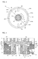
- FIG. 1 is a schematic longitudinal sectional view of a scroll compressor according to Embodiment 1.
- Fig. 2 is an exploded perspective view of a main frame, an orbiting scroll, and other components of the scroll compressor according to Embodiment 1 of the present invention.
- the compressor illustrated in Fig. 1 is a vertical scroll compressor to be used with the central axis of a crank shaft, which will be described later, being substantially vertical to the ground.
- the upper portion is referred to as one end portion U
- the lower portion portion close to the ground
- the scroll compressor includes a shell 1, a main frame 2, a compression mechanism unit 3, a drive mechanism unit 4, a sub-frame 5, a crank shaft 6, a bushing 7, and a power feed unit 8.
- the shell 1 made of an electrically conductive material such as metal is a cylindrical housing having both ends that are closed.
- the shell 1 includes a main shell 11, a lower shell 12, and an upper shell 13.
- the main shell 11 has a cylindrical shape and includes a suction pipe 111 at a side wall of the main shell 11.
- the suction pipe 111 is for introducing refrigerant into the shell 1 and communicates with the inside of the main shell 11.
- the lower shell 12 is a substantially semispherical bottom body. A part of a side wall of the lower shell 12 is connected to the lower end part of the main shell 11 by, for example, welding. Thus, an opening at the lower portion of the main shell 11 is closed by the lower shell 12.
- the upper shell 13 is a substantially semispherical lid body. A part of a side wall of the upper shell 13 is connected to the upper end part of the main shell 11 by, for example, welding. Thus, an opening at the upper portion of the main shell 11 is closed by the upper shell 13.
- the upper shell 13 includes a discharge pipe 131 at an upper part of the upper shell 13. The discharge pipe 131 is for discharge of the refrigerant from the shell 1 and communicates with an inner space of the main shell 11.
- the shell 1 is supported by a fixing base 122 having a plurality of threaded holes.
- the scroll compressor can be fixed to another part such as a housing of an outdoor unit by screwing screws into these threaded holes.
- the main frame 2 is a hollow metal supporting part and has an opening at a portion of the main frame 2 close to the one end portion U.
- the main frame 2 is disposed in the shell 1.
- the main frame 2 includes a main body part 21, a main bearing part 22, and a lubricant return pipe 23.
- the main body part 21 is fixedly supported on an inner circumferential surface of a portion of the main shell 11 close to the one end portion U by shrinkage fitting, welding, or other method.
- An accommodating space 211 is defined in the main body part 21 along the longitudinal direction of the shell 1.
- the accommodating space 211 is open at a portion of the accommodating space 211 close to the one end portion U and has a stepped shape in which the inner space reduces stepwise toward the other end portion L. As illustrated in Fig. 2 , one of surfaces of the stepped portion facing the one end portion U corresponds to a thrust surface 212 having a ring shape.
- the main frame 2 has refrigerant channels 213.
- Each of the refrigerant channels 213 is disposed in a part of an outer circumferential portion of the thrust surface 212 and a part of an inner wall surface of the main frame 2 continuous with the part of the thrust surface 212.
- the refrigerant channels 213 are holes through which the inside and the outside of the main frame 2 are spatially communicated with each other.
- a pair of the refrigerant channels 213 are provided to be arranged on a substantially straight line across the axis of the crank shaft 6 (for example, the central axis of a main shaft part 61, which will be described later).
- an Oldham disposing part 214 is formed at a part of the step portion of the main frame 2 closer the other end portion L than is the thrust surface 212.
- the Oldham disposing part 214 has first Oldham grooves 215.
- the outer end portion of each of the first Oldham grooves 215 extends to a part of the inner circumferential portion of the thrust surface 212.
- a pair of the first Oldham grooves 215 are provided to be arranged on a substantially straight line across the axis of the crank shaft 6.
- the first Oldham grooves 215 each correspond to a frame Oldham groove of the present invention.
- a thrust plate 216 made of a steel-based material is disposed on the thrust surface 212.
- the thrust plate 216 has a ring-shape and is disposed on the thrust surface 212, thereby covering a part of each of the refrigerant channels 213 and a part of each of the first Oldham grooves 215.
- the thrust plate 216 serves as a thrust bearing according to Embodiment 1.
- the main bearing part 22 is formed at a portion closer to the other end portion L than is the main body part 21 and continuous with the main body part 21.
- the main bearing part 22 has a shaft hole 221 inside the main bearing part 22.
- the shaft hole 221 vertically penetrates through the main bearing part 22.
- a portion of the shaft hole 221 close to the one end portion U communicates with the accommodating space 211.
- the lubricant 9 stored in the accommodating space 211 is returned to the lubricant storage 121 of the lower shell 12 through the lubricant return pipe 23.
- the lubricant return pipe 23 is connected to a lubricant discharge hole 218 opened in a wall part 217 facing a weight part 722 of the bushing 7, which will be described later.
- the lubricant 9 is a refrigerating machine oil containing, for example, an ester-based synthetic oil.
- the lubricant 9 is stored in the lubricant storage 121 of the lower shell 12.
- the lubricant 9 has, for example, good lubricating characteristics, good electrical insulating properties, high stability, high dissolubility in the refrigerant, and high fluidity at low-temperature. It is also preferable that the lubricant 9 has an appropriate viscosity.
- the compression mechanism unit 3 compresses the refrigerant.
- the compression mechanism unit 3 is a scroll compression mechanism that includes a fixed scroll 31 and an orbiting scroll 32.
- the fixed scroll 31 is made of metal such as aluminum and cast iron and includes a first base plate 311 and a first scroll body 312.
- the first base plate 311 has a discoidal shape. An outer end part of the first base plate 311 is in contact with the main body part 21 and fixed to the main frame 2 with screws or other component.
- the first scroll body 312 projects from a surface of the first base plate 311 close to the other end portion Lto form a scroll-shaped wall. A distal end of the first scroll body 312 faces the other end portion L.
- the orbiting scroll 32 is made of metal such as aluminum and cast iron and includes a second base plate 321, a second scroll body 322, a cylindrical part 323, and second Oldham grooves 324.
- the second base plate 321 has a discoidal shape.
- the second base plate 321 is supported (borne) by the main frame 2 such that at least a part of an outer circumferential region of an other-end surface 3212 is slidable against the thrust surface 212, which is the thrust plate 216 according to Embodiment 1.
- the second scroll body 322 projects from a one-end surface 3211 of the second base plate 321 to form a scroll-shaped wall.
- a distal end of the second scroll body 322 faces the one end portion U.
- a sealing part that reduces leakage of the refrigerant is provided at the distal end part of each of the first scroll body 312 of the fixed scroll 31 and the second scroll body 322 of the orbiting scroll 32.
- the cylindrical part 323 is a cylindrical boss that projects from the center or the proximity of the center of the other-end surface 3212 of the second base plate 321 toward the other end portion L.
- the second Oldham grooves 324 each have an oblong circular shape and are formed in the other-end surface 3212 of the second base plate 321.
- a pair of the second Oldham grooves 324 are provided to be arranged on a substantially straight line across the axis of the crank shaft 6.
- the second Oldham grooves 324 each correspond to an orbiting-scroll Oldham groove of the present invention.
- an Oldham ring 33 is provided in the Oldham disposing part 214 of the main frame 2.
- the Oldham ring 33 includes a ring part 331, first projections 332, and second projections 333.
- the ring part 331 has a ring shape and is disposed in a space defined between the main frame 2 and the second base plate 321 of the orbiting scroll 32.
- a pair of the first projections 332 are formed on a surface of the ring part 331 close to the other end portion L and face each other.
- a pair of the second projections 333 are formed on a surface of the ring part 331 close to the one end portion U and face each other.
- the pair of first projections 332 are accommodated in the pair of first Oldham grooves 215 of the main frame 2.
- the pair of second projections 333 are accommodated in the pair of second Oldham grooves 324 of the orbiting scroll 32.
- the Oldham ring 33 prevents the orbiting scroll 32 from rotating about its own axis.
- a compression space 34 is defined by engaging the first scroll body 312 of the fixed scroll 31 and the second scroll body 322 of the orbiting scroll 32 with each other.
- the compression space 34 includes a plurality of sub-compression spaces. The volumes of the sub-compression spaces reduce from the radially outer side toward the radially inner side. The refrigerant is sucked in from outer ends of the scroll bodies and the orbiting scroll 32 orbits. This action gradually compresses the refrigerant.
- the compression space 34 communicates with a discharge port 313 that penetrates through a central part of the first base plate 311 of the fixed scroll 31. The compressed refrigerant is discharged through this discharge port 313.
- a discharge valve 35 and a muffler 36 are fixed to a surface of the fixed scroll 31 close to the one end portion U with, for example, screws.
- the discharge valve 35 opens and closes the discharge port 313 as specified to prevent backflow of the refrigerant.
- the muffler 36 has a discharge hole 361 and covers the discharge port 313 and the discharge valve 35.
- the refrigerant is, for example, halogenated hydrocarbon having a double bond of carbon in the composition, halogenated hydrocarbon having no double bond of carbon in the composition, hydrocarbon, or a mixture containing one of these hydrocarbons.
- halogenated hydrocarbon having a double bond of carbon include an HFO refrigerant having zero ozone depletion potential and tetrafluoropropene such as HFO1234yf, HFO1234ze, and HFO1243zf, which are each a fluorocarbon-based low GWP refrigerant and represented by a chemical formula C 3 H 2 F 4 .
- halogenated hydrocarbon having no double bond of carbon examples include a refrigerant mixed with R32 (difluoromethane) represented as CH 2 F 2 , R41, or other similar refrigerant.
- R32 difluoromethane
- hydrocarbon examples include a natural refrigerant such as propane and propylene.
- the mixture examples include a mixed refrigerant in which HFO1234yf, HFO1234ze, HFO1243zf, or other similar refrigerant is mixed with R32, R41, or other similar refrigerant.
- the drive mechanism unit 4 is provided at a portion closer to the other end portion L than is the main frame 2 in the shell 1.
- the drive mechanism unit 4 includes a stator 41 and a rotor 42.
- the stator 41 has a ring shape and is formed by, for example, winding a wire around a core, which is formed by laminating a plurality of electromagnetic steel sheets, with an insulating layer interposed between the core and the wire.
- An outer circumferential surface of the stator 41 is fixedly supported at the inside of the main shell 11 by shrinkage fitting or other method.
- the rotor 42 includes a permanent magnet disposed in a core formed by laminating a plurality of electromagnetic steel sheets.
- the rotor 42 has a cylindrical shape having a through hole that vertically penetrates through the rotor 42 at the center.
- the rotor 42 is disposed in an inner space of the stator 41.
- the sub-frame 5 is a metal supporting part and provided at a portion closer to the other end portion L than is the drive mechanism unit 4 in the shell 1.
- the sub-frame 5 is fixedly supported on an inner circumferential surface of a portion of the main shell 11 close to the other end portion L by shrinkage fitting, welding, or other method.
- the sub-frame 5 includes a sub-bearing part 51 and an oil pump 52.
- the sub-bearing part 51 is a ball bearing provided at an upper central part of the sub-frame 5.
- the sub-bearing part 51 has a hole that vertically penetrates through at its center.
- the oil pump 52 is provided at a lower central part of the sub-frame 5.
- the oil pump 52 is disposed such that at least a part of the oil pump 52 is immersed in the lubricant 9 stored in the lubricant storage 121 of the shell 1.
- the crank shaft 6 is a rod-shaped long metal part and provided in the shell 1.
- the crank shaft 6 includes the main shaft part 61, an eccentric shaft part 62, and the lubricant channel 63.
- An outer surface of the main shaft part 61 is press-fitted into and fixed to the through hole of the rotor 42.
- the central axis of the main shaft part 61 corresponds to the central axis of the main shell 11.
- the eccentric shaft part 62 is provided at a portion closer to the one end portion U than is the main shaft part 61 such that the central axis of the eccentric shaft part 62 is decentered from the central axis of the main shaft part 61.
- the lubricant channel 63 vertically penetrates through the main shaft part 61 and the eccentric shaft part 62.
- the eccentric shaft part 62 of the crank shaft 6 close to the one end portion U is inserted into and fixed to the cylinder of the cylindrical part 323.
- a portion of the crank shaft 6 close to the other end portion L is inserted into and fixed to the sub-bearing part 51 of the sub-frame 5.
- the main shaft part 61 of the crank shaft 6 is positioned in the main bearing part 22 of the main frame 2, and an outer surface of the rotor 42 is disposed in the stator 41 with a specified gap maintained between the outer surface of the rotor 42 and an inner surface of the stator 41.
- the bushing 7 connects the orbiting scroll 32 and the crank shaft 6 to each other.
- the bushing 7 includes two parts, that is, a slider 71 and a balance weight 72.
- the slider 71 is a cylindrical part made of, for example, metal such as iron.
- the slider 71 is fitted onto the eccentric shaft part 62 and fitted into the cylindrical part 323.
- the balance weight 72 is a ring-shaped part made of, for example, metal such as iron.
- the balance weight 72 includes an annular part 721 and the weight part 722.
- the annular part 721 has a ring shape.
- An inner surface of the annular part 721 is engaged with an outer surface of a flange of the slider 71 by a method such as shrinkage fitting.
- the weight part 722 is a weight having a substantially C shape seen from the one end portion U.
- the weight part 722 is formed on a surface of the annular part 721 close to the one end portion U.
- the weight part 722 is disposed at a portion further to the outside than is the cylindrical part 323, specifically, disposed in a portion of the accommodating space 211 defined by the main frame 2, the second base plate 321, and the cylindrical part 323, that is, a space to serve as an intra-frame lubricant storage.
- the power feed unit 8 feeds power to the scroll compressor and is provided on an outer circumferential surface of the main shell 11 of the shell 1.
- the power feed unit 8 includes a cover 81, a power feed terminal 82, and wiring 83.
- the cover 81 has a bottom and an opening.
- the power feed terminal 82 includes a metal part.
- One side of the power feed terminal 82 is provided inside the cover 81 and the other side of the power feed terminal 82 is provided in the shell 1.
- the wiring 83 is connected to the power feed terminal 82 at one end and connected to the stator 41 at the other end.
- Fig. 3 illustrates the orbiting scroll seen from the other end portion L.
- the eccentric shaft part 62 of the crank shaft 6 and the slider 71 of the bushing 7 disposed in the cylindrical part 323 of the orbiting scroll 32 are sectioned.
- the orbiting scroll 32 further includes a lubricant channel groove 325, a first inner channel 326, and a second inner channel 327.
- the lubricant channel groove 325 is an annular groove formed in an outer circumferential region of the other-end surface 3212 of the second base plate 321. Parts of the lubricant channel groove 325 are spatially continuous with the pair of second Oldham grooves 324.
- a first sliding surface 3212a is formed at a portion further to the inside than is the lubricant channel groove 325 and a second sliding surface 3212b is formed at a portion further to the outside than is the lubricant channel groove 325.
- the lubricant channel groove 325 is interposed between the first sliding surface 3212a and the second sliding surface 3212b.
- An outer circumferential portion of the first sliding surface 3212a and an inner circumferential portion of the lubricant channel groove 325 are continuously connected to each other, and an outer circumferential portion of the lubricant channel groove 325 and an inner circumferential portion of the second sliding surface 3212b are continuously connected to each other.
- the width of the second sliding surface 3212b is smaller than the width of the first sliding surface 3212a.
- sliding surface refers to a surface to slide against the thrust bearing while the orbiting scroll is orbiting. Thus, the sliding surface is not determined only by the orbiting scroll 32. The sliding surface is determined depending on the positional relationship between the orbiting scroll 32 and the thrust bearing.
- the first inner channel 326 is connected to the inside of the cylindrical part 323 at one end and connected to the lubricant channel groove 325 at the other end.
- the second inner channel 327 has the similar structure to the structure of the first inner channel 326.
- the second inner channel 327 is provided in a portion facing the first inner channel 326 across the axis of the crank shaft 6.
- the first inner channel 326 and the center of the second base plate 321 are provided on a substantially straight line.
- a flat surface 711 is formed on an outer wall surface of the slider 71.
- a lubricant flowing space 73 is defined by the flat surface 711 of the bushing 7 and an inner wall surface of the cylindrical part 323.
- the amount M1 of the lubricant 9 flowing through the lubricant flowing space 73 and the amount M2 of the lubricant 9 flowing through the first inner channel 326 can be adjusted by the sectional area S1 of the lubricant flowing space 73 or the sectional area S2 of the first inner channel 326 or by, for example, providing resistance in the channel.
- the relationship between the second inner channel 327 and the lubricant flowing space 73 is similar to the relationship between the first inner channel 326 and the lubricant flowing space 73.
- Fig. 4 is an enlarged view of a region surrounded by a dotted chain line X illustrated in Fig. 1 .
- Fig. 5 is an enlarged view of a region surrounded by a dotted chain line Y illustrated in Fig. 4 .
- Fig. 6 is an enlarged view of a region surrounded by a dotted chain line Z illustrated in Fig. 4 .
- the first inner channel 326 and the second inner channel 327 are formed along the other-end surface 3212 of the second base plate 321.
- the state expressed as "along the other-end surface 3212" is optimum when the first inner channel 326 and the second inner channel 327 are parallel to the other-end surface 3212.
- a state in which the first inner channel 326 and the second inner channel 327 are inclined to the other-end surface 3212 by about ⁇ 10 degrees is tolerable.
- the thickness part 3213 produces an effect of ensuring the strength of a central part of the second base plate 321 to be subjected to a pressure increased by compression of the refrigerant.
- the thickness part 3213 also produces an effect of smoothly introducing the lubricant 9 sucked by the crank shaft 6 to the first inner channel 326 and the second inner channel 327 along an inclined surface of the thickness part 3213.
- a first plug part 328 and a second plug part 329 are respectively inserted into an outer end of the first inner channel 326 and an outer end of the second inner channel 327 from side portions.
- the first plug part 328 and the second plug part 329 are, for example, metal screws each made of a material having linear expansion coefficient close to linear expansion coefficients of the fixed scroll 31 and the orbiting scroll 32.
- the first plug part 328 and the second plug part 329 are respectively inserted into and fixed to the first inner channel 326 and the second inner channel 327 by being screwed into respective thread grooves formed in the first inner channel 326 and the second inner channel 327.
- the first plug part 328 and the second plug part 329 close respective outer end portions of the first inner channel 326 and the second inner channel 327. As illustrated in Fig.
- the second plug part 329 has a through hole 3291 at the center.
- the through hole 3291 penetrates through the second plug part 329 in the inside-outside direction.
- the second plug part 329 serves as an adjustment part with which a discharge amount of the lubricant 9 at the outer end portion of the second inner channel 327 (side surface of the second base plate 321) is adjusted. The details of the adjustment part will be described later.
- the first inner channel 326 is a lateral hole and most of the lateral hole extends along the other-end surface 3212.
- the first inner channel 326 is connected to the lubricant channel groove 325 in the vicinity of the outer end of the first inner channel 326 through a first connection hole 3261.
- the first connection hole 3261 is opened in the second base plate 321 to be inclined to the other-end surface 3212 of the second base plate 321.
- the first connection hole 3261 extends from the proximity of a distal end of the first plug part 328 of the first inner channel 326 toward a portion that is close to the other end portion L and close to the outside to be connected to the lubricant channel groove 325.
- the first connection hole 3261 is opened through a portion of the second base plate 321 that is closer to the other end portion L than is the first plug part 328.
- the lubricant channel groove 325 can be formed at a position close to the outer end.
- the lubricant channel groove 325 easily faces the thrust surface 212 (thrust plate 216).
- the lubricant 9 can be effectively supplied to the thrust plate 216.
- the widths of the first sliding surface 3212a and the second sliding surface 3212b can also be adjusted. Furthermore, as the first connection hole 3261 is inclined, the lubricant 9 flowing through the first inner channel 326 can smoothly flow into the lubricant channel groove 325. Also, the second inner channel 327 is connected to the lubricant channel groove 325 through a second connection hole 3271.
- the structure of the second connection hole 3271 is similar to the structure of the first connection hole 3261.
- the lubricant channel groove 325 is formed in an outer circumferential region of the other-end surface 3212 of the second base plate.
- a hole is opened from the side surface of the second base plate 321 to an inner space of the cylindrical part 323 along the other-end surface 3212 by, for example, a drill.
- the first inner channel 326 is formed.
- a hole is opened by, for example, a drill in an inclined direction from the lubricant channel groove 325 toward a portion that is close to the one end portion U and close to the center of the second base plate 321, thereby the first connection hole 3261 connected to the first inner channel 326 is formed.
- a thread groove is formed in a circumferential surface of the first inner channel 326 by specified distance from the side surface of the second base plate 321.
- the second inner channel 327 is formed in a similar method.
- the lubricant channel groove 325 provided between the first sliding surface 3212a and the second sliding surface 3212b of the other-end surface 3212 of the orbiting scroll 32 does not protrude from the thrust plate 216 serving as the thrust bearing. That is, the lubricant channel groove 325 is in such a positional relationship with the thrust plate 216 that the lubricant channel groove 325 faces the thrust plate 216.
- the refrigerant sucked into the shell 1 through the suction pipe 111 enters the compression space 34 through the refrigerant channels 213 of the main frame 2.
- the orbiting scroll 32 orbiting in a decentered manner the refrigerant is reduced in volume and compressed while being moved from an outer circumferential part toward the center.
- the orbiting scroll 32 orbiting in a decentered manner is moved together with the bushing 7 in the radial direction due to the centrifugal force of the orbiting scroll 32, thereby the second scroll body 322 and the first scroll body 312 are brought into close contact with each other. This action prevents leakage of the refrigerant from a high-pressure portion to a lower-pressure portion in the compression space 34.
- the compressed refrigerant is discharged through the discharge port 313 of the fixed scroll 31 while pushing against the discharge valve 35 and discharged from the shell 1 through the discharge hole 361 of the muffler 36 and the discharge pipe 131.
- the lubricant 9 stored in the lubricant storage 121 of the shell 1 is sucked by the oil pump 52.
- the lubricant 9 passes through the lubricant channel 63 of the crank shaft 6 and flows into a space between a distal end of the eccentric shaft part 62 and the orbiting scroll 32, that is, an upflow lubricant storage. As illustrated in Fig.
- the flow of the lubricant 9 having flowed into the upflow lubricant storage is split into a flow flowing through a space between the cylindrical part 323 of the orbiting scroll 32 and the slider 71, a flow flowing through the first inner channel 326, and a flow flowing through the second inner channel 327.
- the flow of the lubricant 9 flowing through the space between the cylindrical part 323 of the orbiting scroll 32 and the slider 71, in particular, flowing through the lubricant flowing space 73 is further split into a flow flowing through a portion close to the main bearing part 22 of the main frame 2 and a flow flowing through a portion close to the intra-frame lubricant storage.
- the lubricant 9 flowing through the portion close to the main bearing part 22 of the main frame 2 lubricates the portion where friction is produced between the main bearing part 22 and the crank shaft 6.
- the lubricant 9 flowing through the intra-frame lubricant storage is, as illustrated in Fig.
- the lubricant 9 flowing through the first inner channel 326 is supplied to the lubricant channel groove 325 through the first connection hole 3261. Then, the lubricant 9 flows through the lubricant channel groove 325 while being guided by the wall inside the lubricant channel groove 325 and entirely lubricates a region between the outer circumferential region of the other-end surface 3212 of the second base plate 321 and the thrust plate 216.
- the excessive lubricant 9 drops into the intra-frame lubricant storage through the second Oldham grooves 324 and the surface of the thrust plate 216, and then, is returned to the lubricant storage 121 through the lubricant discharge hole 218 and the lubricant return pipe 23.
- the lubricant 9 flowing through the second inner channel 327 flows in the direction of the second connection hole 3271 and, a part of the lubricant 9 flowing through the second inner channel 327 flows in the direction of the second plug part 329.
- the lubricant 9 flowing in the direction of the second connection hole 3271 flows into the lubricant channel groove 325 and lubricates the other-end surface 3212 of the second base plate 321 and the thrust plate 216.
- the flow amount of the lubricant 9 having flowed to the second plug part 329 is adjusted by the through hole 3291.
- the lubricant 9 is discharged through the side surface of the second base plate 321.
- the amount of the lubricant 9 discharged through the second plug part 329 can be adjusted also by the viscosity.
- the flow of the lubricant 9 having discharged through the side surface of the second base plate 321 is further split into a flow flowing toward the thrust plate 216 and a flow flowing up toward the one-end surface 3211 of the second base plate 321, that is, subjected to lubricant upflow.
- the lubricant 9 having flowed toward the thrust plate 216 lubricates the region between the other-end surface 3212 of the second base plate 321 and the thrust plate 216.
- the lubricant 9 flowing up toward the fixed scroll 31 enters the compression space 34, thereby lubricating a portion where the orbiting scroll 32 slides against the fixed scroll 31 and serving as a seal that prevents leakage of the refrigerant through the gaps between the scroll bodies and the base plates.
- the upflow amount of the lubricant 9 is excessively large, the lubricant 9 is moved to a heat exchanger through the discharge pipe 131 of the shell 1 and stored in the heat exchanger. This action causes reduction of heat exchange efficiency.
- the amount of the lubricant is excessively small, the amount of the lubricant 9 supplied to the region where the orbiting scroll 32 slides against the fixed scroll 31 is reduced. This action causes insufficient lubrication and insufficient sealing.
- the discharge amount of the lubricant 9 through the second plug part 329 be adjusted to be an appropriate upflow amount of the lubricant 9.
- the area of the channel of the through hole 3291 for the lubricant 9 is made to be smaller than the area of the channel of the second inner channel 327.
- the diameter of the hole of the second inner channel 327 is R1 and the diameter of the through hole 3291 is R2, a relationship of which R2/R1 is from 30 to 50% is satisfied.
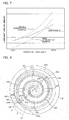
- Fig. 7 explains the lubricant upflows according to Embodiment 1 and comparative examples.
- a first comparative example corresponds to a compressor in which, as is the case with Patent Literature 1, the intra-frame lubricant storage is filled with the lubricant 9 and the lubricant 9 flows up due to an overflow caused by a lubricant pressure.
- a second comparative example corresponds to a compressor in which the total amount of the lubricant 9 is increased from that of the first comparative example.
- Embodiment 1 and the first and second comparative examples As can be seen from Fig. 7 , according to Embodiment 1 and the first and second comparative examples, as the operating frequency increases, the amount of the lubricant upflow increases. However, variation of the lubricant upflow amount between high-speed operation and low-speed operation is smaller with Embodiment 1 than with the first or second comparative example. That is, according to Embodiment 1, the lubricant upflow amount is stable even when the operating frequency varies. In contrast, according to the first comparative example, although an appropriate lubricant upflow amount can be obtained at middle to high operating frequencies, the lubricant upflow amount is excessively small at low frequencies.
- the lubricant upflow amount is excessively small, insufficient lubrication or insufficient sealing for the fixed scroll 31 and the orbiting scroll 32 may be caused.
- the lubricant upflow amount is excessive at high frequencies.
- the lubricant 9 is moved to the heat exchanger through the discharge pipe 131 of the shell 1 and a refrigerant pipe and stored in the heat exchanger, and thus, the heat exchange efficiency is likely to reduce.
- the amount of the sucked up lubricant varies in proportion to the operating frequency.
- the amount of the sucked up lubricant reduces at low operating frequencies and increases at high operating frequencies.
- the amount of the lubricant supplied to the thrust bearing and the amount of the lubricant flowing upward and supplied to the compression space are determined in proportion to the amount of the lubricant stored in the intra-frame lubricant storage.
- the flow amount of the lubricant 9 sucked up by the crank shaft 6 is adjusted by the second plug part 329 through the second inner channel 327, and then, this lubricant 9 is discharged from the side surface of the second base plate 321 of the orbiting scroll 32 and made to flow upward.
- the amount of the lubricant 9 involved in the lubricant upflow can be adjusted.
- variation of the lubricant upflow amount can be reduced even when the operating frequency varies.
- effects of the operating frequency are reduced, and an appropriate amount of the lubricant can flow upward in operation at low to high operating frequencies.
- the configuration can be used in which the lubricant discharge hole 218 is opened in the wall part 217 of the main frame 2 facing the weight part 722 of the bushing 7 to actively return the lubricant 9 in the intra-frame lubricant storage to the lubricant storage 121 of the lower shell 12 through the lubricant return pipe 23.
- the lubricant discharge hole 218 be opened below the weight part 722, that is, in the proximity of the wall part 217 facing the side surface of the annular part 721 so that almost no part of the weight part 722 is immersed in the lubricant 9.
- the agitation loss is significant during high-speed rotation of the crank shaft 6, during operation under the conditions that reduces the temperature of the lubricant 9, and during use of the lubricant 9 having high viscosity grade.
- the present structure is usable under such design and use conditions.
- the present structure significantly responds to the needs of the market.
- Fig. 8 illustrates the main frame and the orbiting scroll seen from the one end portion.
- an angle ⁇ formed between a line L1 and a line L2 is 10 degrees or smaller.
- the line L1 connects the center of the hole of the second inner channel 327 formed in the side surface of the second base plate 321 of the orbiting scroll 32 and a center C of the second base plate 321 to each other.
- the line L2 connects an outermost end part 3221 of the second scroll body 322 and the center C of the second base plate 321 to each other. That is, the hole of the side surface of the second inner channel 327 is opened in the proximity of the outermost end part 3221 of the second scroll body 322, that is, in the proximity of a winding end.
- This configuration facilitates entrance, through the winding end of the second scroll body 322, of the lubricant 9 having been discharged through the through hole 3291 of the second plug part 329 and flowed upward. As a result, the lubricant 9 can be efficiently supplied to the compression space 34.
- the lubricant 9 flowing upward can be efficiently introduced into the compression space 34 as long as the angle ⁇ is 10 degrees or smaller.
- a similar effect can be obtained when the angle ⁇ formed between the line L1 and a line L2 is 10 degrees or smaller in the case where line L1 connects the center of the hole of the second inner channel 327 formed in the side surface of the second base plate 321 of the orbiting scroll 32 and the center C of the second base plate 321 to each other, and the line L2 in this case connects an outermost end part (winding end) of the first scroll body 312 of the fixed scroll 31 and the center C of the second base plate 321 to each other.
- an angle ⁇ formed between the line L1 and a line L3 is 45 degrees or smaller.
- the line L1 connects the hole of the second inner channel 327 opened in the side surface of the second base plate 321 of the orbiting scroll 32 and the center C of the second base plate 321 to each other.
- the line L3 connects one of the refrigerant channels 213 of the main frame 2 and the center C of the second base plate 321 to each other. That is, the hole of the side surface of the second inner channel 327 is disposed in the proximity of the one of the refrigerant channels 213, through which the refrigerant passes between the inside and the outside of the main frame 2.
- the orbiting scroll 32 orbits against the main frame 2
- variation of timing causes the angle ⁇ to vary.
- the above-described relationship is satisfied at any timing during the orbiting.
- the lubricant 9 can be made to flow upward together with the refrigerant by using a suction pressure caused when the refrigerant passes through the refrigerant channels 213.
- Fig. 9 includes views that explain orbiting states of the orbiting scroll against the main frame.
- View (a) illustrates a reference state
- view (b) illustrates a state in which the crank shaft is rotated through 1/4 of a turn from the reference state
- view (c) illustrates a state in which the crank shaft is rotated through 1/2 of a turn from the reference state
- view (d) illustrates a state in which the crank shaft is rotated through 3/4 of a turn from the reference state.
- FIG. 9 View (a) of Fig. 9 illustrates the same state as the state illustrated in, for example, Figs. 1 and 4 .
- the lubricant channel groove 325 stays within a region of the thrust plate 216 and faces the thrust plate 216.
- view (b) of Fig. 9 when the crank shaft is rotated through 1/4 of a turn from the reference state, the position of the orbiting scroll 32 is relatively shifted to the right from the reference state in sectional view.
- the lubricant channel groove 325 stays within the region of the thrust plate 216 and faces the thrust plate 216.
- view (c) of Fig. 9 when the crank shaft is rotated through 1/2 of a turn from the reference state, the position of the orbiting scroll 32 is relatively shifted further to the right. Even in this state, the lubricant channel groove 325 stays within the region of the thrust plate 216 and faces the thrust plate 216.
- the orbiting scroll 32 orbits, for example, counterclockwise against the main frame 2 seen from the one end portion U, and the states of views (a), (b), (c), and (d) of Fig. 9 are repeated.
- the lubricant channel groove 325 stays within the region of the thrust plate 216 and constantly faces the thrust plate 216.
- the lubricant 9 leaks toward the intra-frame lubricant storage at this timing to improve lubrication for a portion in which insufficient lubrication is likely to be locally caused by using the lubricant channel groove 325 according to Embodiment 1. That is, as the lubricant 9 is constantly supplied to the thrust plate 216 through the lubricant channel groove 325, the entirety of the portion where the orbiting scroll 32 slides against the thrust plate 216 can be stably lubricated.
- the lubricant 9 in the upflow lubricant storage of the orbiting scroll 32 is directly introduced to the thrust bearing, time for the lubricant 9 to reach the thrust bearing can be reduced. Thus, even for a test run or a startup after a long-time stop, seizure of the thrust bearing can be prevented.
- a refrigerant containing R32 which is a high-pressure refrigerant that is likely to increase in pressure
- the lubricant 9 is stably supplied to the thrust bearing.
- seizure or other defect of the thrust bearing can be reduced.
- a thrust load exerted on the thrust bearing increases.
- the fact that the pressure of R32 is high becomes a problem.
- this problem is likely to be solved with Embodiment 1.
- a crank shaft, an orbiting scroll, and a frame are provided.
- the crank shaft has a lubricant channel that allows a lubricant to flow through the lubricant channel.
- the orbiting scroll is attached to the crank shaft.
- the frame has a thrust surface against which the orbiting scroll slides.
- the orbiting scroll has an inner channel and a lubricant channel groove.
- the inner channel allows the lubricant supplied through the crank shaft to flow outward.
- the lubricant channel groove faces the thrust surface and allows the lubricant supplied through the inner channel to be supplied to the thrust surface.
- the lubricant channel groove is formed such that the lubricant channel groove stays within the region of the thrust surface while the orbiting scroll is orbiting.
- the lubricant channel groove faces the thrust surface during orbiting of the orbiting scroll.
- the orbiting scroll has a first sliding surface and a second sliding surface.
- the first sliding surface is provided at a portion further to the inside than is the lubricant channel groove.
- the second sliding surface is provided at a portion further to the outside than is the lubricant channel groove and has a smaller width than the width of the first sliding surface.
- the orbiting scroll has a base plate and a cylindrical part that projects from one surface of the base plate.
- the lubricant channel groove is formed in the one surface of the base plate.
- the inner channel is connected to the inside of the cylindrical part at one end and connected to the lubricant channel groove at the other end.
- the base plate has a discoidal shape, and the lubricant channel groove is an annular groove provided in an outer circumferential region of the base plate.
- the inner channel is formed along the one surface of the base plate and has a connection hole connected to the lubricant channel groove. Furthermore, the connection hole is inclined from the inner channel outward to be connected to the lubricant channel groove.
- a forming position of the lubricant channel groove 325 can be provided close to the outer end of the other-end surface 3212 of the second base plate 321. This configuration can facilitate forming of such a lubricant channel groove 325 that stays within a region of the thrust bearing while the orbiting scroll 32 is orbiting.
- the inner channel penetrates an outer end surface of the base plate.
- a plug part is inserted at an outer end portion of the inner channel.
- the inner channel includes a first inner channel and a second inner channel provided opposite to the first inner channel across the axis of the crank shaft.
- the plug part is provided in the first inner channel, and an adjustment part is provided in the second inner channel.
- the adjustment part adjusts the flow amount of the lubricant and allows the lubricant to be discharged from the side surface of the base plate.
- the second inner channel allows an appropriate amount of the lubricant 9 that can flow upward to flow through.
- sealing properties and sliding properties between the fixed scroll 31 and the orbiting scroll 32 can be preferable.
- a bushing that connects the orbiting scroll and the crank shaft to each other is further provided.
- the bushing includes a weight part provided at a portion of the bushing further to the outside than is the cylindrical part.
- the frame has a lubricant discharge hole at a wall part of the frame facing the weight part. This configuration can reduce the occurrence of the agitation loss of the weight part 722 caused by filling, with the lubricant 9, the space in the main frame 2 in which the weight part 722 of the bushing 7 is disposed.
- the bushing has a flat surface that faces an inner wall surface of the cylindrical part of the orbiting scroll.
- the amount of the lubricant 9 supplied to a portion where the crank shaft 6 slides against the main bearing part 22 can be larger than the amount of the lubricant 9 supplied to a portion where the orbiting scroll 32 and the thrust bearing orbit against each other.
- a relationship of 0.05 ⁇ M2/(M1 + M2) ⁇ 0.3 is satisfied, an appropriate balance between the amount of the lubricant 9 supplied to the portion where the crank shaft 6 slides against the main bearing part 22 and the amount of the lubricant 9 supplied to the portion where the orbiting scroll 32 and the thrust bearing orbit against each other can be obtained.
- the frame further has an Oldham groove that accommodates a part of an Oldham ring and a thrust plate provided on the thrust surface.
- a part of the Oldham groove is formed in the thrust surface.
- the orbiting scroll slides against the thrust plate, and the thrust plate covers at least a part of the Oldham groove.
- tolerance against a thrust load can be improved by the thrust plate 216.
- this configuration can reduce the occurrence of lubricant shortage due to flowing, through the second Oldham grooves 324, of the lubricant 9 moving through the lubricant channel groove 325.
- the lubricant 9 can be stably supplied to the thrust bearing. Thus, seizure or other defect of the thrust bearing can be reduced. Also, even when a refrigerant that is difficult to flow upward due to low density of the refrigerant such as HFO-1234yf is used in the refrigeration cycle apparatus, lubricant can stably flow upward.
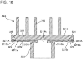
- Fig. 10 is a sectional view of the structure of an orbiting scroll of the scroll compressor according to Embodiment 2 of the present invention.
- parts having the same structures as those illustrated in Figs. 1 to 9 are denoted with the same reference signs, thereby description of the parts is omitted.
- an orbiting scroll 32A has a projection 3213A projecting toward the center, at its portion close to the one end portion U in the cylindrical part 323.
- a lubricant storage space 3214A is defined at the center of a portion of the cylindrical part 323 close to the one end portion U.
- This lubricant storage space 3214A is resistive before the lubricant 9 sucked through the crank shaft 6 flows into the first inner channel 326 and the second inner channel 327.
- the flow amount of the lubricant 9 flowing through the first inner channel 326 and the second inner channel 327 can be adjusted.
- This configuration is particularly effective when it is desirable to limit the flow amount of the lubricant 9 flowing through the second inner channel 327, which includes the second plug part 329 serving as the adjustment part.
- a first connection hole 3261A and a second connection hole 3271A are vertical holes orthogonal to the other-end surface 3212.
- these holes are easily produced compared to the case where these holes are inclined holes.
- the present invention is not limited to the invention according to Embodiment 1 or Embodiment 2 having been described, and the present invention may be appropriately modified without departing from the gist of the present invention.
- the scroll compressor according to Embodiment 1 or Embodiment 2 having been described is a vertical scroll compressor
- the techniques herein can also be applied to a horizontal scroll compressor.
- the scroll compressor according to Embodiment 1 or Embodiment 2 having been described is a low-pressure-shell scroll compressor
- the techniques herein can also be applied to a high-pressure-shell scroll compressor.
- the thrust load applied to the thrust surface 212 by the orbiting scroll 32 the auxiliary effect of the suction of the refrigerant through the refrigerant channels 213 of the main frame 2 on lubricant upflow of the lubricant 9, and other factor are considered, the present invention is more suitable to the low-pressure-shell scroll compressor.
- the thrust plate 216 is not necessarily provided. Instead, against the thrust surface 212, the orbiting scroll 32 may slide.
- the first sliding surface 3212a and the second sliding surface 3212b which are ring-shaped flat surfaces projecting from the other-end surface 3212 toward the other end portion L, may be flat surfaces at the same level as the level of the other-end surface 3212, that is, flush with the other-end surface 3212.
- the lubricant channel groove 325 is not necessarily an annular groove.
- the lubricant channel groove 325 may be terminated by, for example, the second Oldham grooves 324 as long as the lubricant 9 can be sufficiently supplied to the entirety of the thrust bearing.
- the lubricant channel groove 325 does not necessarily have a ring shape, either.
- an inner channel that includes the second plug part 329 and is used for lubricant upflow may be provided.
- the sectional shape of the inner channels is not limited to a perfect-circular shape and may be, for example, an oval shape, an oblate circular shape, or a polygonal shape.
- the second connection hole 3271 may be omitted when the lubricant 9 can be sufficiently supplied to the entirety of the thrust bearing by the first connection hole 3261 of the first inner channel 326 and the lubricant channel groove 325.
- the second inner channel 327 may instead be dedicated to adjustment of the flow amount of the lubricant 9 for lubricant upflow.
- adjustment of the flow amount by the second plug part 329 can be facilitated.
- the first plug part 328 and the second plug part 329 are not necessarily metal screws. That is, as long as the first plug part 328 and the second plug part 329 can be inserted into and fixed to the holes of the first inner channel 326 and the second inner channel 327, the first plug part 328 and the second plug part 329 may be metal pins to be connected by an adhesive or elastic parts such as rubber to be connected by being press-fitted.
- the method of adjusting the flow amount of the lubricant 9 using the second plug part 329 is not limited to the through hole 3291.
- the method with which the adjustment is performed, for example, by utilizing the gap between the second base plate 321 and the second plug part 329 may be used.
- the through hole 3291 does not necessarily extend along the other-end surface 3212.
- the through hole 3291 may be inclined in a lubricant upflow direction (outward and toward the one end portion U) to facilitate lubricant upflow.
- the diameter of the through hole 3291 may be varied.
Abstract
Description
- The present invention relates to a scroll compressor and a lubricant supplying structure.
- In a scroll compressor, an orbiting scroll orbits against a fixed scroll, thereby compressing refrigerant in a compression space defined by scroll laps of the orbiting scroll and the fixed scroll. This orbiting scroll is accommodated in a frame. A thrust load produced during orbiting of the orbiting scroll is supported by a thrust bearing provided in the frame. During the orbiting of the orbiting scroll, the orbiting scroll slides against the thrust bearing of the frame. Thus, it is required that lubricant be supplied to the thrust bearing to prevent seizure or other defect. A variety of methods have been proposed as a method of supplying lubricant to the thrust bearing.
- For example, there is a structure with which lubricant sucked up by a crank shaft is stored in a space between a frame and an orbiting scroll, and the lubricant is caused to overflow to be supplied to a thrust bearing (for example, see Patent Literature 1).
- Furthermore, there is a structure in which an annular groove is provided in a lower surface of an orbiting scroll to supply lubricant to a thrust bearing (for example, see Patent Literature 2). Furthermore, there is a structure in which an annular groove in a lower surface of an orbiting scroll and a drive bushing chamber are connected to each other through a lubricant hole (for example, see Patent Literature 3).
-
- Patent Literature 1: Japanese Unexamined Patent Application Publication No.
2014-169677 - Patent Literature 2: International Publication No.
2015/155802 - Patent Literature 3: Japanese Unexamined Patent Application Publication No.
5-149277 - However, in the case of a test run or startup after a long-time stop, the lubricant is not stored in the frame. Thus, with the structure of
Patent Literature 1, the lubricant cannot be supplied to the thrust bearing for a period of time from when operation of the compressor is started to when the lubricant overflows. This inability may lead to a failure of the compressor due to seizure. - Furthermore, according to
Patent Literature 2 andPatent Literature 3, the annular groove is formed in a comparatively central region in the lower surface of the orbiting scroll. Thus, effective supply of the lubricant to the thrust bearing may fail during the orbiting of the orbiting scroll. This failure may lead to lubricant shortage at the thrust bearing. - The present invention has been made to address the above-described problem. An object of the present invention is to provide a scroll compressor and a refrigeration cycle apparatus in which sufficient lubricant can be supplied to a thrust bearing.
- A scroll compressor of one embodiment of the present invention includes a crank shaft, an orbiting scroll, and a frame. The crank shaft has a lubricant channel allowing lubricant to flow through the lubricant channel. The orbiting scroll is attached to the crank shaft and includes a base plate that is discoidal. The frame has a thrust surface against which the orbiting scroll slides. The thrust surface has an annular shape and faces an outer circumferential region of one surface of the base plate of the orbiting scroll. The orbiting scroll has an inner channel and a lubricant channel groove. The inner channel allows the lubricant supplied through the crank shaft to flow outward. The lubricant channel groove has an annular shape in the outer circumferential region of the one surface of the base plate facing the thrust surface and allows the lubricant supplied through the inner channel to be supplied to the thrust surface. The lubricant channel groove is formed such that the lubricant channel groove stays within a region of the thrust surface while the orbiting scroll is orbiting.
- According to one embodiment of the present invention, the scroll compressor and the refrigeration cycle apparatus in which sufficient lubricant can be supplied to the thrust bearing can be provided.
-
- [
Fig. 1] Fig. 1 is a schematic longitudinal sectional view of a scroll compressor according toEmbodiment 1 of the present invention. - [
Fig. 2] Fig. 2 is an exploded perspective view of a main frame, an orbiting scroll, and other components of the scroll compressor according toEmbodiment 1 of the present invention. - [
Fig. 3] Fig. 3 illustrates the orbiting scroll seen from an other end portion L. - [
Fig. 4] Fig. 4 is an enlarged view of a region surrounded by a dotted chain line X illustrated inFig. 1 . - [
Fig. 5] Fig. 5 is an enlarged view of a region surrounded by a dotted chain line Y illustrated inFig. 4 . - [
Fig. 6] Fig. 6 is an enlarged view of a region surrounded by a dotted chain line Z illustrated inFig. 4 . - [
Fig. 7] Fig. 7 explains lubricant upflows according toEmbodiment 1 and comparative examples. - [
Fig. 8] Fig. 8 illustrates the main frame and the orbiting scroll seen from the one end portion. - [
Fig. 9] Fig. 9 includes views that explain orbiting states of the orbiting scroll against the main frame, and out of views (a) to (d), view (a) illustrates a reference state, view (b) illustrates a state in which a crank shaft is rotated through 1/4 of a turn from the reference state, view (c) illustrates a state in which the crank shaft is rotated through 1/2 of a turn from the reference state, and view (d) illustrates a state in which the crank shaft is rotated through 3/4 of a turn from the reference state. - [
Fig. 10] Fig. 10 is a sectional view of an orbiting scroll of the scroll compressor according toEmbodiment 2 of the present invention. - Embodiments of the present invention will be described below with reference to the drawings. In the drawings, the same or equivalent parts are denoted with the same reference signs, thereby description of the parts is appropriately omitted or simplified. Furthermore, the shapes, sizes, arrangements, and other aspects of structures illustrated in the drawings can be appropriately changed within the scope of the present invention.
-
Embodiment 1 is described below.Fig. 1 is a schematic longitudinal sectional view of a scroll compressor according toEmbodiment 1.Fig. 2 is an exploded perspective view of a main frame, an orbiting scroll, and other components of the scroll compressor according toEmbodiment 1 of the present invention. The compressor illustrated inFig. 1 is a vertical scroll compressor to be used with the central axis of a crank shaft, which will be described later, being substantially vertical to the ground. Regarding the directions, the upper portion is referred to as one end portion U, and the lower portion (portion close to the ground) is referred to as an other end portion L for description. - The scroll compressor includes a
shell 1, amain frame 2, acompression mechanism unit 3, adrive mechanism unit 4, asub-frame 5, acrank shaft 6, abushing 7, and apower feed unit 8. - The
shell 1 made of an electrically conductive material such as metal is a cylindrical housing having both ends that are closed. Theshell 1 includes amain shell 11, alower shell 12, and anupper shell 13. Themain shell 11 has a cylindrical shape and includes asuction pipe 111 at a side wall of themain shell 11. Thesuction pipe 111 is for introducing refrigerant into theshell 1 and communicates with the inside of themain shell 11. Thelower shell 12 is a substantially semispherical bottom body. A part of a side wall of thelower shell 12 is connected to the lower end part of themain shell 11 by, for example, welding. Thus, an opening at the lower portion of themain shell 11 is closed by thelower shell 12. - At least a part of the inside of the
lower shell 12 is used as alubricant storage 121 in whichlubricant 9 is stored. Theupper shell 13 is a substantially semispherical lid body. A part of a side wall of theupper shell 13 is connected to the upper end part of themain shell 11 by, for example, welding. Thus, an opening at the upper portion of themain shell 11 is closed by theupper shell 13. Theupper shell 13 includes adischarge pipe 131 at an upper part of theupper shell 13. Thedischarge pipe 131 is for discharge of the refrigerant from theshell 1 and communicates with an inner space of themain shell 11. Theshell 1 is supported by a fixingbase 122 having a plurality of threaded holes. The scroll compressor can be fixed to another part such as a housing of an outdoor unit by screwing screws into these threaded holes. - The
main frame 2 is a hollow metal supporting part and has an opening at a portion of themain frame 2 close to the one end portion U. Themain frame 2 is disposed in theshell 1. Themain frame 2 includes amain body part 21, amain bearing part 22, and alubricant return pipe 23. Themain body part 21 is fixedly supported on an inner circumferential surface of a portion of themain shell 11 close to the one end portion U by shrinkage fitting, welding, or other method. Anaccommodating space 211 is defined in themain body part 21 along the longitudinal direction of theshell 1. Theaccommodating space 211 is open at a portion of theaccommodating space 211 close to the one end portion U and has a stepped shape in which the inner space reduces stepwise toward the other end portion L. As illustrated inFig. 2 , one of surfaces of the stepped portion facing the one end portion U corresponds to athrust surface 212 having a ring shape. - The
main frame 2 has refrigerantchannels 213. Each of therefrigerant channels 213 is disposed in a part of an outer circumferential portion of thethrust surface 212 and a part of an inner wall surface of themain frame 2 continuous with the part of thethrust surface 212. Therefrigerant channels 213 are holes through which the inside and the outside of themain frame 2 are spatially communicated with each other. A pair of therefrigerant channels 213 are provided to be arranged on a substantially straight line across the axis of the crank shaft 6 (for example, the central axis of amain shaft part 61, which will be described later). - Furthermore, an
Oldham disposing part 214 is formed at a part of the step portion of themain frame 2 closer the other end portion L than is thethrust surface 212. TheOldham disposing part 214 hasfirst Oldham grooves 215. The outer end portion of each of thefirst Oldham grooves 215 extends to a part of the inner circumferential portion of thethrust surface 212. A pair of thefirst Oldham grooves 215 are provided to be arranged on a substantially straight line across the axis of thecrank shaft 6. Thefirst Oldham grooves 215 each correspond to a frame Oldham groove of the present invention. - A
thrust plate 216 made of a steel-based material is disposed on thethrust surface 212. Thethrust plate 216 has a ring-shape and is disposed on thethrust surface 212, thereby covering a part of each of therefrigerant channels 213 and a part of each of thefirst Oldham grooves 215. Thus, thethrust plate 216 serves as a thrust bearing according toEmbodiment 1. - The
main bearing part 22 is formed at a portion closer to the other end portion L than is themain body part 21 and continuous with themain body part 21. Themain bearing part 22 has ashaft hole 221 inside themain bearing part 22. Theshaft hole 221 vertically penetrates through themain bearing part 22. A portion of theshaft hole 221 close to the one end portion U communicates with theaccommodating space 211. Thelubricant 9 stored in theaccommodating space 211 is returned to thelubricant storage 121 of thelower shell 12 through thelubricant return pipe 23. Thelubricant return pipe 23 is connected to alubricant discharge hole 218 opened in awall part 217 facing aweight part 722 of thebushing 7, which will be described later. - The
lubricant 9 is a refrigerating machine oil containing, for example, an ester-based synthetic oil. Thelubricant 9 is stored in thelubricant storage 121 of thelower shell 12. Thelubricant 9, through alubricant channel 63 of thecrank shaft 6, reduces wear of parts in mechanical contact with one another, adjusts the temperatures of sliding portions, and improves sealing properties. Preferably, thelubricant 9 has, for example, good lubricating characteristics, good electrical insulating properties, high stability, high dissolubility in the refrigerant, and high fluidity at low-temperature. It is also preferable that thelubricant 9 has an appropriate viscosity. - The
compression mechanism unit 3 compresses the refrigerant. According toEmbodiment 1, thecompression mechanism unit 3 is a scroll compression mechanism that includes a fixedscroll 31 and anorbiting scroll 32. The fixedscroll 31 is made of metal such as aluminum and cast iron and includes afirst base plate 311 and afirst scroll body 312. - The
first base plate 311 has a discoidal shape. An outer end part of thefirst base plate 311 is in contact with themain body part 21 and fixed to themain frame 2 with screws or other component. Thefirst scroll body 312 projects from a surface of thefirst base plate 311 close to the other end portion Lto form a scroll-shaped wall. A distal end of thefirst scroll body 312 faces the other end portion L. The orbitingscroll 32 is made of metal such as aluminum and cast iron and includes asecond base plate 321, asecond scroll body 322, acylindrical part 323, andsecond Oldham grooves 324. - The
second base plate 321 has a discoidal shape. Thesecond base plate 321 is supported (borne) by themain frame 2 such that at least a part of an outer circumferential region of an other-end surface 3212 is slidable against thethrust surface 212, which is thethrust plate 216 according toEmbodiment 1. Thesecond scroll body 322 projects from a one-end surface 3211 of thesecond base plate 321 to form a scroll-shaped wall. A distal end of thesecond scroll body 322 faces the one end portion U. A sealing part that reduces leakage of the refrigerant is provided at the distal end part of each of thefirst scroll body 312 of the fixedscroll 31 and thesecond scroll body 322 of the orbitingscroll 32. Thecylindrical part 323 is a cylindrical boss that projects from the center or the proximity of the center of the other-end surface 3212 of thesecond base plate 321 toward the other end portion L. - The
second Oldham grooves 324 each have an oblong circular shape and are formed in the other-end surface 3212 of thesecond base plate 321. A pair of thesecond Oldham grooves 324 are provided to be arranged on a substantially straight line across the axis of thecrank shaft 6. Thesecond Oldham grooves 324 each correspond to an orbiting-scroll Oldham groove of the present invention. - Furthermore, an
Oldham ring 33 is provided in theOldham disposing part 214 of themain frame 2. TheOldham ring 33 includes aring part 331,first projections 332, andsecond projections 333. Thering part 331 has a ring shape and is disposed in a space defined between themain frame 2 and thesecond base plate 321 of the orbitingscroll 32. A pair of thefirst projections 332 are formed on a surface of thering part 331 close to the other end portion L and face each other. A pair of thesecond projections 333 are formed on a surface of thering part 331 close to the one end portion U and face each other. The pair offirst projections 332 are accommodated in the pair offirst Oldham grooves 215 of themain frame 2. The pair ofsecond projections 333 are accommodated in the pair ofsecond Oldham grooves 324 of the orbitingscroll 32. Thus, when the orbitingscroll 32 orbits due to rotation of thecrank shaft 6, theOldham ring 33 prevents the orbitingscroll 32 from rotating about its own axis. - A
compression space 34 is defined by engaging thefirst scroll body 312 of the fixedscroll 31 and thesecond scroll body 322 of the orbitingscroll 32 with each other. Thecompression space 34 includes a plurality of sub-compression spaces. The volumes of the sub-compression spaces reduce from the radially outer side toward the radially inner side. The refrigerant is sucked in from outer ends of the scroll bodies and the orbitingscroll 32 orbits. This action gradually compresses the refrigerant. Thecompression space 34 communicates with adischarge port 313 that penetrates through a central part of thefirst base plate 311 of the fixedscroll 31. The compressed refrigerant is discharged through thisdischarge port 313. Adischarge valve 35 and amuffler 36 are fixed to a surface of the fixedscroll 31 close to the one end portion U with, for example, screws. Thedischarge valve 35 opens and closes thedischarge port 313 as specified to prevent backflow of the refrigerant. Themuffler 36 has adischarge hole 361 and covers thedischarge port 313 and thedischarge valve 35. - The refrigerant is, for example, halogenated hydrocarbon having a double bond of carbon in the composition, halogenated hydrocarbon having no double bond of carbon in the composition, hydrocarbon, or a mixture containing one of these hydrocarbons. Examples of the halogenated hydrocarbon having a double bond of carbon include an HFO refrigerant having zero ozone depletion potential and tetrafluoropropene such as HFO1234yf, HFO1234ze, and HFO1243zf, which are each a fluorocarbon-based low GWP refrigerant and represented by a chemical formula C3H2F4. Examples of the halogenated hydrocarbon having no double bond of carbon include a refrigerant mixed with R32 (difluoromethane) represented as CH2F2, R41, or other similar refrigerant. Examples of the hydrocarbon include a natural refrigerant such as propane and propylene. Examples of the mixture include a mixed refrigerant in which HFO1234yf, HFO1234ze, HFO1243zf, or other similar refrigerant is mixed with R32, R41, or other similar refrigerant.
- The
drive mechanism unit 4 is provided at a portion closer to the other end portion L than is themain frame 2 in theshell 1. Thedrive mechanism unit 4 includes a stator 41 and a rotor 42. The stator 41 has a ring shape and is formed by, for example, winding a wire around a core, which is formed by laminating a plurality of electromagnetic steel sheets, with an insulating layer interposed between the core and the wire. An outer circumferential surface of the stator 41 is fixedly supported at the inside of themain shell 11 by shrinkage fitting or other method. The rotor 42 includes a permanent magnet disposed in a core formed by laminating a plurality of electromagnetic steel sheets. The rotor 42 has a cylindrical shape having a through hole that vertically penetrates through the rotor 42 at the center. The rotor 42 is disposed in an inner space of the stator 41. - The
sub-frame 5 is a metal supporting part and provided at a portion closer to the other end portion L than is thedrive mechanism unit 4 in theshell 1. Thesub-frame 5 is fixedly supported on an inner circumferential surface of a portion of themain shell 11 close to the other end portion L by shrinkage fitting, welding, or other method. Thesub-frame 5 includes asub-bearing part 51 and anoil pump 52. Thesub-bearing part 51 is a ball bearing provided at an upper central part of thesub-frame 5. Thesub-bearing part 51 has a hole that vertically penetrates through at its center. Theoil pump 52 is provided at a lower central part of thesub-frame 5. Theoil pump 52 is disposed such that at least a part of theoil pump 52 is immersed in thelubricant 9 stored in thelubricant storage 121 of theshell 1. - The
crank shaft 6 is a rod-shaped long metal part and provided in theshell 1. Thecrank shaft 6 includes themain shaft part 61, aneccentric shaft part 62, and thelubricant channel 63. An outer surface of themain shaft part 61 is press-fitted into and fixed to the through hole of the rotor 42. The central axis of themain shaft part 61 corresponds to the central axis of themain shell 11. Theeccentric shaft part 62 is provided at a portion closer to the one end portion U than is themain shaft part 61 such that the central axis of theeccentric shaft part 62 is decentered from the central axis of themain shaft part 61. Thelubricant channel 63 vertically penetrates through themain shaft part 61 and theeccentric shaft part 62. Theeccentric shaft part 62 of thecrank shaft 6 close to the one end portion U is inserted into and fixed to the cylinder of thecylindrical part 323. A portion of thecrank shaft 6 close to the other end portion L is inserted into and fixed to thesub-bearing part 51 of thesub-frame 5. Thus, themain shaft part 61 of thecrank shaft 6 is positioned in themain bearing part 22 of themain frame 2, and an outer surface of the rotor 42 is disposed in the stator 41 with a specified gap maintained between the outer surface of the rotor 42 and an inner surface of the stator 41. - The
bushing 7 connects the orbitingscroll 32 and thecrank shaft 6 to each other. According toEmbodiment 1, thebushing 7 includes two parts, that is, aslider 71 and abalance weight 72. Theslider 71 is a cylindrical part made of, for example, metal such as iron. Theslider 71 is fitted onto theeccentric shaft part 62 and fitted into thecylindrical part 323. - The
balance weight 72 is a ring-shaped part made of, for example, metal such as iron. Thebalance weight 72 includes anannular part 721 and theweight part 722. Theannular part 721 has a ring shape. An inner surface of theannular part 721 is engaged with an outer surface of a flange of theslider 71 by a method such as shrinkage fitting. As illustrated inFig. 2 , theweight part 722 is a weight having a substantially C shape seen from the one end portion U. Theweight part 722 is formed on a surface of theannular part 721 close to the one end portion U. Theweight part 722 is disposed at a portion further to the outside than is thecylindrical part 323, specifically, disposed in a portion of theaccommodating space 211 defined by themain frame 2, thesecond base plate 321, and thecylindrical part 323, that is, a space to serve as an intra-frame lubricant storage. - The
power feed unit 8 feeds power to the scroll compressor and is provided on an outer circumferential surface of themain shell 11 of theshell 1. Thepower feed unit 8 includes acover 81, apower feed terminal 82, andwiring 83. Thecover 81 has a bottom and an opening. Thepower feed terminal 82 includes a metal part. One side of thepower feed terminal 82 is provided inside thecover 81 and the other side of thepower feed terminal 82 is provided in theshell 1. Thewiring 83 is connected to thepower feed terminal 82 at one end and connected to the stator 41 at the other end. - Next, further details of the structure of the orbiting
scroll 32 are described with reference toFig. 3. Fig. 3 illustrates the orbiting scroll seen from the other end portion L. Theeccentric shaft part 62 of thecrank shaft 6 and theslider 71 of thebushing 7 disposed in thecylindrical part 323 of the orbitingscroll 32 are sectioned. - As can be seen from
Fig. 3 , the orbitingscroll 32 further includes alubricant channel groove 325, a firstinner channel 326, and a secondinner channel 327. Thelubricant channel groove 325 is an annular groove formed in an outer circumferential region of the other-end surface 3212 of thesecond base plate 321. Parts of thelubricant channel groove 325 are spatially continuous with the pair ofsecond Oldham grooves 324. A first slidingsurface 3212a is formed at a portion further to the inside than is thelubricant channel groove 325 and a second slidingsurface 3212b is formed at a portion further to the outside than is thelubricant channel groove 325. That is, thelubricant channel groove 325 is interposed between the first slidingsurface 3212a and the second slidingsurface 3212b. An outer circumferential portion of the first slidingsurface 3212a and an inner circumferential portion of thelubricant channel groove 325 are continuously connected to each other, and an outer circumferential portion of thelubricant channel groove 325 and an inner circumferential portion of the second slidingsurface 3212b are continuously connected to each other. Preferably, the width of the second slidingsurface 3212b is smaller than the width of the first slidingsurface 3212a. Here, "sliding surface" refers to a surface to slide against the thrust bearing while the orbiting scroll is orbiting. Thus, the sliding surface is not determined only by the orbitingscroll 32. The sliding surface is determined depending on the positional relationship between the orbitingscroll 32 and the thrust bearing. - The first
inner channel 326 is connected to the inside of thecylindrical part 323 at one end and connected to thelubricant channel groove 325 at the other end. The secondinner channel 327 has the similar structure to the structure of the firstinner channel 326. The secondinner channel 327 is provided in a portion facing the firstinner channel 326 across the axis of thecrank shaft 6. The firstinner channel 326 and the center of thesecond base plate 321 are provided on a substantially straight line. - As illustrated in
Fig. 3 , aflat surface 711 is formed on an outer wall surface of theslider 71. Alubricant flowing space 73 is defined by theflat surface 711 of thebushing 7 and an inner wall surface of thecylindrical part 323. When the sectional area of thelubricant flowing space 73 is S1 and the sectional area of the firstinner channel 326 is S2, a relationship of S1 > S2 is satisfied. - When the
lubricant 9 flows, resistance is smaller in thelubricant flowing space 73 than in the firstinner channel 326. Thus, when the amount of thelubricant 9 flowing through thelubricant flowing space 73 is M1 and the amount of thelubricant 9 flowing through the firstinner channel 326 is M2, a relationship of M1 > M2 can be established. Thus, the amount of thelubricant 9 supplied to a portion where friction is produced between themain bearing part 22 and thecrank shaft 6 is larger than the amount of thelubricant 9 supplied to a portion where the orbitingscroll 32 slides against the thrust bearing. Furthermore, when a relationship of 0.05 < M2/(M1 + M2) < 0.3 is satisfied, an appropriate balance between the amount of thelubricant 9 supplied to the portion where friction is produced between themain bearing part 22 and thecrank shaft 6 and the amount of thelubricant 9 supplied to the portion where the orbitingscroll 32 slides against the thrust bearing can be obtained. - The amount M1 of the
lubricant 9 flowing through thelubricant flowing space 73 and the amount M2 of thelubricant 9 flowing through the firstinner channel 326 can be adjusted by the sectional area S1 of thelubricant flowing space 73 or the sectional area S2 of the firstinner channel 326 or by, for example, providing resistance in the channel. The relationship between the secondinner channel 327 and thelubricant flowing space 73 is similar to the relationship between the firstinner channel 326 and thelubricant flowing space 73. - Further details of the first
inner channel 326, the secondinner channel 327, and other components are described with reference toFigs. 4 to 6 .Fig. 4 is an enlarged view of a region surrounded by a dotted chain line X illustrated inFig. 1 .Fig. 5 is an enlarged view of a region surrounded by a dotted chain line Y illustrated inFig. 4 .Fig. 6 is an enlarged view of a region surrounded by a dotted chain line Z illustrated inFig. 4 . - As illustrated in
Fig. 4 , the firstinner channel 326 and the secondinner channel 327 are formed along the other-end surface 3212 of thesecond base plate 321. The state expressed as "along the other-end surface 3212" is optimum when the firstinner channel 326 and the secondinner channel 327 are parallel to the other-end surface 3212. However, a state in which the firstinner channel 326 and the secondinner channel 327 are inclined to the other-end surface 3212 by about ±10 degrees is tolerable. A thickness part 3213 that is frusto-conical, the diameter of which gradually reduces toward the other end portion L, is formed at inner ends of the firstinner channel 326 and the secondinner channel 327 inside thecylindrical part 323, that is, around the center of the other-end surface 3212 of thesecond base plate 321. - The thickness part 3213 produces an effect of ensuring the strength of a central part of the
second base plate 321 to be subjected to a pressure increased by compression of the refrigerant. The thickness part 3213 also produces an effect of smoothly introducing thelubricant 9 sucked by thecrank shaft 6 to the firstinner channel 326 and the secondinner channel 327 along an inclined surface of the thickness part 3213. - A
first plug part 328 and asecond plug part 329 are respectively inserted into an outer end of the firstinner channel 326 and an outer end of the secondinner channel 327 from side portions. Thefirst plug part 328 and thesecond plug part 329 are, for example, metal screws each made of a material having linear expansion coefficient close to linear expansion coefficients of the fixedscroll 31 and the orbitingscroll 32. Thefirst plug part 328 and thesecond plug part 329 are respectively inserted into and fixed to the firstinner channel 326 and the secondinner channel 327 by being screwed into respective thread grooves formed in the firstinner channel 326 and the secondinner channel 327. Thefirst plug part 328 and thesecond plug part 329 close respective outer end portions of the firstinner channel 326 and the secondinner channel 327. As illustrated inFig. 6 , out of these plug parts, thesecond plug part 329 has a throughhole 3291 at the center. The throughhole 3291 penetrates through thesecond plug part 329 in the inside-outside direction. Thesecond plug part 329 serves as an adjustment part with which a discharge amount of thelubricant 9 at the outer end portion of the second inner channel 327 (side surface of the second base plate 321) is adjusted. The details of the adjustment part will be described later. - The first
inner channel 326 is a lateral hole and most of the lateral hole extends along the other-end surface 3212. Thus, the firstinner channel 326 is connected to thelubricant channel groove 325 in the vicinity of the outer end of the firstinner channel 326 through afirst connection hole 3261. Thefirst connection hole 3261 is opened in thesecond base plate 321 to be inclined to the other-end surface 3212 of thesecond base plate 321. Specifically, thefirst connection hole 3261 extends from the proximity of a distal end of thefirst plug part 328 of the firstinner channel 326 toward a portion that is close to the other end portion L and close to the outside to be connected to thelubricant channel groove 325. - As illustrated in
Fig. 5 , when the length by which thefirst plug part 328 is inserted from the outer end surface of thesecond base plate 321 is D1 and a minimum distance between the outer end surface of thesecond base plate 321 and thefirst connection hole 3261 is D2, a relationship of D1 > D2 is satisfied. That is, thefirst connection hole 3261 is opened through a portion of thesecond base plate 321 that is closer to the other end portion L than is thefirst plug part 328. Thus, thelubricant channel groove 325 can be formed at a position close to the outer end. Thus, when the orbitingscroll 32 is disposed in themain frame 2, thelubricant channel groove 325 easily faces the thrust surface 212 (thrust plate 216). Thus, thelubricant 9 can be effectively supplied to thethrust plate 216. - The widths of the first sliding
surface 3212a and the second slidingsurface 3212b can also be adjusted. Furthermore, as thefirst connection hole 3261 is inclined, thelubricant 9 flowing through the firstinner channel 326 can smoothly flow into thelubricant channel groove 325. Also, the secondinner channel 327 is connected to thelubricant channel groove 325 through asecond connection hole 3271. The structure of thesecond connection hole 3271 is similar to the structure of thefirst connection hole 3261. - An example of a method of forming the first
inner channel 326 and other components is described. First, thelubricant channel groove 325 is formed in an outer circumferential region of the other-end surface 3212 of the second base plate. Next, a hole is opened from the side surface of thesecond base plate 321 to an inner space of thecylindrical part 323 along the other-end surface 3212 by, for example, a drill. Thereby, the firstinner channel 326 is formed. Then, a hole is opened by, for example, a drill in an inclined direction from thelubricant channel groove 325 toward a portion that is close to the one end portion U and close to the center of thesecond base plate 321, thereby thefirst connection hole 3261 connected to the firstinner channel 326 is formed. At last, a thread groove is formed in a circumferential surface of the firstinner channel 326 by specified distance from the side surface of thesecond base plate 321. With this method, the firstinner channel 326 and other components can be easily formed. The secondinner channel 327 is formed in a similar method. - Next, operation of the scroll compressor is described. When the power is supplied to the
power feed terminal 82 of thepower feed unit 8, torque is produced in the stator 41 and the rotor 42, thereby thecrank shaft 6 is rotated. The rotation of thecrank shaft 6 is transmitted to theorbiting scroll 32 through theeccentric shaft part 62 and thebushing 7. The rotation of the orbitingscroll 32 about its own axis is prevented by theOldham ring 33, and the orbitingscroll 32 orbits in a decentered manner. At this time, the first slidingsurface 3212a and the second slidingsurface 3212b slide against thethrust plate 216. Thus, thelubricant channel groove 325 provided between the first slidingsurface 3212a and the second slidingsurface 3212b of the other-end surface 3212 of the orbitingscroll 32 does not protrude from thethrust plate 216 serving as the thrust bearing. That is, thelubricant channel groove 325 is in such a positional relationship with thethrust plate 216 that thelubricant channel groove 325 faces thethrust plate 216. - Meanwhile, the refrigerant sucked into the
shell 1 through thesuction pipe 111 enters thecompression space 34 through therefrigerant channels 213 of themain frame 2. Then, as the orbitingscroll 32 orbits in a decentered manner, the refrigerant is reduced in volume and compressed while being moved from an outer circumferential part toward the center. The orbitingscroll 32 orbiting in a decentered manner is moved together with thebushing 7 in the radial direction due to the centrifugal force of the orbitingscroll 32, thereby thesecond scroll body 322 and thefirst scroll body 312 are brought into close contact with each other. This action prevents leakage of the refrigerant from a high-pressure portion to a lower-pressure portion in thecompression space 34. Thus, the compression is performed with high efficiency. The compressed refrigerant is discharged through thedischarge port 313 of the fixedscroll 31 while pushing against thedischarge valve 35 and discharged from theshell 1 through thedischarge hole 361 of themuffler 36 and thedischarge pipe 131. - Here, when the orbiting
scroll 32 orbits due to the rotation of thecrank shaft 6, thelubricant 9 stored in thelubricant storage 121 of theshell 1 is sucked by theoil pump 52. Thelubricant 9 passes through thelubricant channel 63 of thecrank shaft 6 and flows into a space between a distal end of theeccentric shaft part 62 and the orbitingscroll 32, that is, an upflow lubricant storage. As illustrated inFig. 4 , the flow of thelubricant 9 having flowed into the upflow lubricant storage is split into a flow flowing through a space between thecylindrical part 323 of the orbitingscroll 32 and theslider 71, a flow flowing through the firstinner channel 326, and a flow flowing through the secondinner channel 327. - The flow of the
lubricant 9 flowing through the space between thecylindrical part 323 of the orbitingscroll 32 and theslider 71, in particular, flowing through thelubricant flowing space 73 is further split into a flow flowing through a portion close to themain bearing part 22 of themain frame 2 and a flow flowing through a portion close to the intra-frame lubricant storage. Thelubricant 9 flowing through the portion close to themain bearing part 22 of themain frame 2 lubricates the portion where friction is produced between themain bearing part 22 and thecrank shaft 6. Thelubricant 9 flowing through the intra-frame lubricant storage is, as illustrated inFig. 4 , returned to thelubricant storage 121 of theshell 1 through thelubricant discharge hole 218 of thewall part 217 of themain frame 2 facing theweight part 722 of thebushing 7 and, by utilizing the self-weight, through thelubricant return pipe 23. - The
lubricant 9 flowing through the firstinner channel 326 is supplied to thelubricant channel groove 325 through thefirst connection hole 3261. Then, thelubricant 9 flows through thelubricant channel groove 325 while being guided by the wall inside thelubricant channel groove 325 and entirely lubricates a region between the outer circumferential region of the other-end surface 3212 of thesecond base plate 321 and thethrust plate 216. After the region between thesecond base plate 321 and thethrust plate 216 has been evenly lubricated, theexcessive lubricant 9 drops into the intra-frame lubricant storage through thesecond Oldham grooves 324 and the surface of thethrust plate 216, and then, is returned to thelubricant storage 121 through thelubricant discharge hole 218 and thelubricant return pipe 23. - As illustrated in
Fig. 6 , thelubricant 9 flowing through the secondinner channel 327 flows in the direction of thesecond connection hole 3271 and, a part of thelubricant 9 flowing through the secondinner channel 327 flows in the direction of thesecond plug part 329. As is the case with thelubricant 9 flowing through the firstinner channel 326, thelubricant 9 flowing in the direction of thesecond connection hole 3271 flows into thelubricant channel groove 325 and lubricates the other-end surface 3212 of thesecond base plate 321 and thethrust plate 216. The flow amount of thelubricant 9 having flowed to thesecond plug part 329 is adjusted by the throughhole 3291. Then, thelubricant 9 is discharged through the side surface of thesecond base plate 321. The amount of thelubricant 9 discharged through thesecond plug part 329 can be adjusted also by the viscosity. - The flow of the
lubricant 9 having discharged through the side surface of thesecond base plate 321 is further split into a flow flowing toward thethrust plate 216 and a flow flowing up toward the one-end surface 3211 of thesecond base plate 321, that is, subjected to lubricant upflow. Thelubricant 9 having flowed toward thethrust plate 216 lubricates the region between the other-end surface 3212 of thesecond base plate 321 and thethrust plate 216. - The
lubricant 9 flowing up toward the fixedscroll 31 enters thecompression space 34, thereby lubricating a portion where the orbitingscroll 32 slides against the fixedscroll 31 and serving as a seal that prevents leakage of the refrigerant through the gaps between the scroll bodies and the base plates. However, when the upflow amount of thelubricant 9 is excessively large, thelubricant 9 is moved to a heat exchanger through thedischarge pipe 131 of theshell 1 and stored in the heat exchanger. This action causes reduction of heat exchange efficiency. In contrast, when the amount of the lubricant is excessively small, the amount of thelubricant 9 supplied to the region where the orbitingscroll 32 slides against the fixedscroll 31 is reduced. This action causes insufficient lubrication and insufficient sealing. To solve this problem, it is preferable that the discharge amount of thelubricant 9 through thesecond plug part 329 be adjusted to be an appropriate upflow amount of thelubricant 9. For example, the area of the channel of the throughhole 3291 for thelubricant 9 is made to be smaller than the area of the channel of the secondinner channel 327. Furthermore, when the diameter of the hole of the secondinner channel 327 is R1 and the diameter of the throughhole 3291 is R2, a relationship of which R2/R1 is from 30 to 50% is satisfied. - Next, the lubricant upflow according to
Embodiment 1 due to variation of an operating frequency (rotation frequency of the crank shaft) of the compressor is described with reference toFig. 7. Fig. 7 explains the lubricant upflows according toEmbodiment 1 and comparative examples. A first comparative example corresponds to a compressor in which, as is the case withPatent Literature 1, the intra-frame lubricant storage is filled with thelubricant 9 and thelubricant 9 flows up due to an overflow caused by a lubricant pressure. A second comparative example corresponds to a compressor in which the total amount of thelubricant 9 is increased from that of the first comparative example. - As can be seen from
Fig. 7 , according toEmbodiment 1 and the first and second comparative examples, as the operating frequency increases, the amount of the lubricant upflow increases. However, variation of the lubricant upflow amount between high-speed operation and low-speed operation is smaller withEmbodiment 1 than with the first or second comparative example. That is, according toEmbodiment 1, the lubricant upflow amount is stable even when the operating frequency varies. In contrast, according to the first comparative example, although an appropriate lubricant upflow amount can be obtained at middle to high operating frequencies, the lubricant upflow amount is excessively small at low frequencies. When the lubricant upflow amount is excessively small, insufficient lubrication or insufficient sealing for the fixedscroll 31 and the orbitingscroll 32 may be caused. According to the second comparative example, although an appropriate lubricant upflow amount can be obtained at low to middle operating frequencies due to the increase in the total amount of thelubricant 9, the lubricant upflow amount is excessive at high frequencies. When the lubricant upflow amount is excessive, thelubricant 9 is moved to the heat exchanger through thedischarge pipe 131 of theshell 1 and a refrigerant pipe and stored in the heat exchanger, and thus, the heat exchange efficiency is likely to reduce. - For a single rotation of the crank shaft, a specified amount of the lubricant is pumped up from the lubricant storage by the oil pump. Thus, the amount of the sucked up lubricant varies in proportion to the operating frequency. The amount of the sucked up lubricant reduces at low operating frequencies and increases at high operating frequencies. In a compressor that causes an overflow of the lubricant such as a compressor of the first or second comparative example, the amount of the lubricant supplied to the thrust bearing and the amount of the lubricant flowing upward and supplied to the compression space are determined in proportion to the amount of the lubricant stored in the intra-frame lubricant storage. Thus, when the amount of the lubricant supplied to the thrust bearing is made to be sufficient for low-speed operation, the lubricant upflow is excessive during high-speed operation. In contrast, when the lubricant upflow amount is made to be appropriate for high-speed operation, the lubricant at the thrust bearing is insufficient during low-speed operation. Thus, it is difficult to supply an appropriate amount of the lubricant for both the high-speed operation and the low-speed operation.
- In contrast, according to
Embodiment 1, the flow amount of thelubricant 9 sucked up by thecrank shaft 6 is adjusted by thesecond plug part 329 through the secondinner channel 327, and then, thislubricant 9 is discharged from the side surface of thesecond base plate 321 of the orbitingscroll 32 and made to flow upward. With this method, the amount of thelubricant 9 involved in the lubricant upflow can be adjusted. Thus, variation of the lubricant upflow amount can be reduced even when the operating frequency varies. Thus, compared to the overflow method, effects of the operating frequency are reduced, and an appropriate amount of the lubricant can flow upward in operation at low to high operating frequencies. Furthermore, as thelubricant 9 in the upflow lubricant storage of the orbitingscroll 32 is made to directly flow upward, time for thelubricant 9 to reach thecompression space 34 can be reduced. Thus, even for a test run or a startup after a long-time stop, sealing properties and lubricating properties between the scrolls can be preferable. - Furthermore, with the method of supplying lubricant to the thrust bearing according to
Embodiment 1, it is not required that the intra-frame lubricant storage be filled with thelubricant 9. Thus, the configuration can be used in which thelubricant discharge hole 218 is opened in thewall part 217 of themain frame 2 facing theweight part 722 of thebushing 7 to actively return thelubricant 9 in the intra-frame lubricant storage to thelubricant storage 121 of thelower shell 12 through thelubricant return pipe 23. - When the amount of the
lubricant 9 in the intra-frame lubricant storage is reduced, the occurrence of an agitation loss, that is, production of resistance in theweight part 722 and theOldham ring 33 due to thelubricant 9 during the rotation of thecrank shaft 6 can be reduced. Such an agitation loss has been typically reduced by increasing the distance between theweight part 722 and an inner wall of themain frame 2. With the present structure, such design is not required. Thus, the size and the weight can be reduced. For further reduction of the agitation loss of theweight part 722, it is preferable that thelubricant discharge hole 218 be opened below theweight part 722, that is, in the proximity of thewall part 217 facing the side surface of theannular part 721 so that almost no part of theweight part 722 is immersed in thelubricant 9. - The agitation loss is significant during high-speed rotation of the
crank shaft 6, during operation under the conditions that reduces the temperature of thelubricant 9, and during use of thelubricant 9 having high viscosity grade. However, the present structure is usable under such design and use conditions. In particular, nowadays, there exist demands for increasing the capacity of compressors for high-speed operation. The present structure significantly responds to the needs of the market. - The lubricant upflow and whether the
lubricant 9 enters thecompression space 34 affect, for example, the positional relationship between thesecond plug part 329 and thesecond scroll body 322 of the orbitingscroll 32. Thus, the positional relationship of these components is described with reference toFig. 8. Fig. 8 illustrates the main frame and the orbiting scroll seen from the one end portion. - As illustrated in
Fig. 8 , an angle α formed between a line L1 and a line L2 is 10 degrees or smaller. Here, the line L1 connects the center of the hole of the secondinner channel 327 formed in the side surface of thesecond base plate 321 of the orbitingscroll 32 and a center C of thesecond base plate 321 to each other. The line L2 connects anoutermost end part 3221 of thesecond scroll body 322 and the center C of thesecond base plate 321 to each other. That is, the hole of the side surface of the secondinner channel 327 is opened in the proximity of theoutermost end part 3221 of thesecond scroll body 322, that is, in the proximity of a winding end. This configuration facilitates entrance, through the winding end of thesecond scroll body 322, of thelubricant 9 having been discharged through the throughhole 3291 of thesecond plug part 329 and flowed upward. As a result, thelubricant 9 can be efficiently supplied to thecompression space 34. - Even in the case where the hole of the side surface of the second
inner channel 327 is positioned closer to a winding start of thesecond scroll body 322 than is theoutermost end part 3221 of thesecond scroll body 322, thelubricant 9 flowing upward can be efficiently introduced into thecompression space 34 as long as the angle α is 10 degrees or smaller. A similar effect can be obtained when the angle α formed between the line L1 and a line L2 is 10 degrees or smaller in the case where line L1 connects the center of the hole of the secondinner channel 327 formed in the side surface of thesecond base plate 321 of the orbitingscroll 32 and the center C of thesecond base plate 321 to each other, and the line L2 in this case connects an outermost end part (winding end) of thefirst scroll body 312 of the fixedscroll 31 and the center C of thesecond base plate 321 to each other. - Furthermore, as illustrated in
Fig. 8 , an angle β formed between the line L1 and a line L3 is 45 degrees or smaller. The line L1 connects the hole of the secondinner channel 327 opened in the side surface of thesecond base plate 321 of the orbitingscroll 32 and the center C of thesecond base plate 321 to each other. The line L3 connects one of therefrigerant channels 213 of themain frame 2 and the center C of thesecond base plate 321 to each other. That is, the hole of the side surface of the secondinner channel 327 is disposed in the proximity of the one of therefrigerant channels 213, through which the refrigerant passes between the inside and the outside of themain frame 2. Thus, thelubricant 9 having been discharged through the throughhole 3291 of thesecond plug part 329 is likely to flow upward together with the refrigerant. As a result, thelubricant 9 can be efficiently supplied to thecompression space 34. - As the
orbiting scroll 32 orbits against themain frame 2, variation of timing causes the angle β to vary. Preferably, the above-described relationship is satisfied at any timing during the orbiting. Furthermore, in the case of a low-pressure shell method in which the refrigerant is sucked through therefrigerant channels 213 of themain frame 2, compressed in thecompression space 34, and discharged through the hole at the central part of the fixedscroll 31, thelubricant 9 can be made to flow upward together with the refrigerant by using a suction pressure caused when the refrigerant passes through therefrigerant channels 213. - Next, further details of the relationship between the
main frame 2 and the orbitingscroll 32 during the orbiting are described with reference toFig. 9. Fig. 9 includes views that explain orbiting states of the orbiting scroll against the main frame. View (a) illustrates a reference state, view (b) illustrates a state in which the crank shaft is rotated through 1/4 of a turn from the reference state, view (c) illustrates a state in which the crank shaft is rotated through 1/2 of a turn from the reference state, and view (d) illustrates a state in which the crank shaft is rotated through 3/4 of a turn from the reference state. - View (a) of
Fig. 9 illustrates the same state as the state illustrated in, for example,Figs. 1 and4 . As described above, thelubricant channel groove 325 stays within a region of thethrust plate 216 and faces thethrust plate 216. As illustrated in view (b) ofFig. 9 , when the crank shaft is rotated through 1/4 of a turn from the reference state, the position of the orbitingscroll 32 is relatively shifted to the right from the reference state in sectional view. - Even in this state, the
lubricant channel groove 325 stays within the region of thethrust plate 216 and faces thethrust plate 216. As illustrated in view (c) ofFig. 9 , when the crank shaft is rotated through 1/2 of a turn from the reference state, the position of the orbitingscroll 32 is relatively shifted further to the right. Even in this state, thelubricant channel groove 325 stays within the region of thethrust plate 216 and faces thethrust plate 216. - As illustrated in view (d) of
Fig. 9 , when the crank shaft is rotated through 3/4 of a turn from the reference state, the position of the orbitingscroll 32 is returned to a state similar to the state illustrated in view (b) ofFig. 9 . Even in this state, thelubricant channel groove 325 stays within the region of thethrust plate 216 and faces thethrust plate 216. - When the
crank shaft 6 is rotated, the orbitingscroll 32 orbits, for example, counterclockwise against themain frame 2 seen from the one end portion U, and the states of views (a), (b), (c), and (d) ofFig. 9 are repeated. Thus, even during the orbiting of the orbitingscroll 32, thelubricant channel groove 325 stays within the region of thethrust plate 216 and constantly faces thethrust plate 216. - When there is timing at which the
lubricant channel groove 325 of the orbitingscroll 32 that is orbiting protrudes from thethrust plate 216, thelubricant 9 leaks toward the intra-frame lubricant storage at this timing to improve lubrication for a portion in which insufficient lubrication is likely to be locally caused by using thelubricant channel groove 325 according toEmbodiment 1. That is, as thelubricant 9 is constantly supplied to thethrust plate 216 through thelubricant channel groove 325, the entirety of the portion where the orbitingscroll 32 slides against thethrust plate 216 can be stably lubricated. Furthermore, as thelubricant 9 in the upflow lubricant storage of the orbitingscroll 32 is directly introduced to the thrust bearing, time for thelubricant 9 to reach the thrust bearing can be reduced. Thus, even for a test run or a startup after a long-time stop, seizure of the thrust bearing can be prevented. - In a refrigeration cycle apparatus that includes a compressor, a condenser, an expansion valve, and an evaporator, use of a refrigerant containing R32, which is a high-pressure refrigerant that is likely to increase in pressure, as the refrigerant increases a burden borne by the thrust bearing. However, according to
Embodiment 1, thelubricant 9 is stably supplied to the thrust bearing. Thus, even when the above-described refrigerant is used, seizure or other defect of the thrust bearing can be reduced. In the low-pressure shell method, in particular, a thrust load exerted on the thrust bearing increases. Thus, the fact that the pressure of R32 is high becomes a problem. However, this problem is likely to be solved withEmbodiment 1. - Alternatively, when a refrigerant containing HFO-1234yf, the density of which is low, is used as the refrigerant of a refrigeration cycle apparatus, lubricant upflow along with suction of the refrigerant through the
refrigerant channels 213 of themain frame 2 of the low-pressure shell method becomes difficult. However, according toEmbodiment 1, control of an appropriate upflow amount of the lubricant is possible due to the function of adjusting the flow amount of thelubricant 9 by using thesecond plug part 329. Thus, even the refrigerant containing HFO-1234yf can be made to stably flow upward. - According to
Embodiment 1, a crank shaft, an orbiting scroll, and a frame are provided. The crank shaft has a lubricant channel that allows a lubricant to flow through the lubricant channel. The orbiting scroll is attached to the crank shaft. The frame has a thrust surface against which the orbiting scroll slides. The orbiting scroll has an inner channel and a lubricant channel groove. The inner channel allows the lubricant supplied through the crank shaft to flow outward. The lubricant channel groove faces the thrust surface and allows the lubricant supplied through the inner channel to be supplied to the thrust surface. The lubricant channel groove is formed such that the lubricant channel groove stays within the region of the thrust surface while the orbiting scroll is orbiting. - That is, the lubricant channel groove faces the thrust surface during orbiting of the orbiting scroll. The orbiting scroll has a first sliding surface and a second sliding surface. The first sliding surface is provided at a portion further to the inside than is the lubricant channel groove. The second sliding surface is provided at a portion further to the outside than is the lubricant channel groove and has a smaller width than the width of the first sliding surface. Thus, during the orbiting of the orbiting scroll, a sufficient amount of the
lubricant 9 can be stably supplied to the thrust bearing. - The orbiting scroll has a base plate and a cylindrical part that projects from one surface of the base plate. The lubricant channel groove is formed in the one surface of the base plate. The inner channel is connected to the inside of the cylindrical part at one end and connected to the lubricant channel groove at the other end. Furthermore, the base plate has a discoidal shape, and the lubricant channel groove is an annular groove provided in an outer circumferential region of the base plate.
- Furthermore, the inner channel is formed along the one surface of the base plate and has a connection hole connected to the lubricant channel groove. Furthermore, the connection hole is inclined from the inner channel outward to be connected to the lubricant channel groove. Thus, a forming position of the
lubricant channel groove 325 can be provided close to the outer end of the other-end surface 3212 of thesecond base plate 321. This configuration can facilitate forming of such alubricant channel groove 325 that stays within a region of the thrust bearing while the orbitingscroll 32 is orbiting. - The inner channel penetrates an outer end surface of the base plate. A plug part is inserted at an outer end portion of the inner channel. When the length by which the plug part is inserted from the outer end surface of the base plate is D1 and a minimum distance between the outer end surface of the base plate and the connection hole is D2, a relationship of D1 > D2 is satisfied. Thus, the channel in the
second base plate 321 for thelubricant 9 can be easily formed while the forming position of thelubricant channel groove 325 is provided close to the outer end of the other-end surface 3212 of thesecond base plate 321. - The inner channel includes a first inner channel and a second inner channel provided opposite to the first inner channel across the axis of the crank shaft. The plug part is provided in the first inner channel, and an adjustment part is provided in the second inner channel. The adjustment part adjusts the flow amount of the lubricant and allows the lubricant to be discharged from the side surface of the base plate. Thus, the second inner channel allows an appropriate amount of the
lubricant 9 that can flow upward to flow through. Thus, sealing properties and sliding properties between the fixedscroll 31 and the orbitingscroll 32 can be preferable. - A bushing that connects the orbiting scroll and the crank shaft to each other is further provided. The bushing includes a weight part provided at a portion of the bushing further to the outside than is the cylindrical part. Furthermore, the frame has a lubricant discharge hole at a wall part of the frame facing the weight part. This configuration can reduce the occurrence of the agitation loss of the
weight part 722 caused by filling, with thelubricant 9, the space in themain frame 2 in which theweight part 722 of thebushing 7 is disposed. - The bushing has a flat surface that faces an inner wall surface of the cylindrical part of the orbiting scroll. When the sectional area of the lubricant flowing space defined by the flat surface and the inner wall surface of the cylindrical part is S1 and the sectional area of the inner channel is S2, a relationship of S1 > S2 is satisfied. Thus, a configuration is possible that satisfies a relationship of M1 > M2, where the amount of the
lubricant 9 flowing through thelubricant flowing space 73 is M1 and the amount of thelubricant 9 flowing through the firstinner channel 326 is M2. Thus, the amount of thelubricant 9 supplied to a portion where thecrank shaft 6 slides against themain bearing part 22 can be larger than the amount of thelubricant 9 supplied to a portion where the orbitingscroll 32 and the thrust bearing orbit against each other. When a relationship of 0.05 < M2/(M1 + M2) < 0.3 is satisfied, an appropriate balance between the amount of thelubricant 9 supplied to the portion where thecrank shaft 6 slides against themain bearing part 22 and the amount of thelubricant 9 supplied to the portion where the orbitingscroll 32 and the thrust bearing orbit against each other can be obtained. - The frame further has an Oldham groove that accommodates a part of an Oldham ring and a thrust plate provided on the thrust surface. A part of the Oldham groove is formed in the thrust surface. The orbiting scroll slides against the thrust plate, and the thrust plate covers at least a part of the Oldham groove. Thus, tolerance against a thrust load can be improved by the
thrust plate 216. In addition, this configuration can reduce the occurrence of lubricant shortage due to flowing, through thesecond Oldham grooves 324, of thelubricant 9 moving through thelubricant channel groove 325. - Even when a high-pressure refrigerant such as R32 is used in the refrigeration cycle apparatus, the
lubricant 9 can be stably supplied to the thrust bearing. Thus, seizure or other defect of the thrust bearing can be reduced. Also, even when a refrigerant that is difficult to flow upward due to low density of the refrigerant such as HFO-1234yf is used in the refrigeration cycle apparatus, lubricant can stably flow upward. -
Fig. 10 is a sectional view of the structure of an orbiting scroll of the scroll compressor according toEmbodiment 2 of the present invention. InFig. 10 , parts having the same structures as those illustrated inFigs. 1 to 9 are denoted with the same reference signs, thereby description of the parts is omitted. - As illustrated in
Fig. 10 , anorbiting scroll 32A according toEmbodiment 2 has aprojection 3213A projecting toward the center, at its portion close to the one end portion U in thecylindrical part 323. Thus, alubricant storage space 3214A is defined at the center of a portion of thecylindrical part 323 close to the one end portion U. Thislubricant storage space 3214A is resistive before thelubricant 9 sucked through thecrank shaft 6 flows into the firstinner channel 326 and the secondinner channel 327. Thus, the flow amount of thelubricant 9 flowing through the firstinner channel 326 and the secondinner channel 327 can be adjusted. This configuration is particularly effective when it is desirable to limit the flow amount of thelubricant 9 flowing through the secondinner channel 327, which includes thesecond plug part 329 serving as the adjustment part. - Furthermore, a
first connection hole 3261A and asecond connection hole 3271A are vertical holes orthogonal to the other-end surface 3212. When thefirst connection hole 3261A and thesecond connection hole 3271A are vertical holes, these holes are easily produced compared to the case where these holes are inclined holes. - The present invention is not limited to the invention according to
Embodiment 1 orEmbodiment 2 having been described, and the present invention may be appropriately modified without departing from the gist of the present invention. - For example, although the scroll compressor according to
Embodiment 1 orEmbodiment 2 having been described is a vertical scroll compressor, the techniques herein can also be applied to a horizontal scroll compressor. - Although the scroll compressor according to
Embodiment 1 orEmbodiment 2 having been described is a low-pressure-shell scroll compressor, the techniques herein can also be applied to a high-pressure-shell scroll compressor. However, when the thrust load applied to thethrust surface 212 by the orbitingscroll 32, the auxiliary effect of the suction of the refrigerant through therefrigerant channels 213 of themain frame 2 on lubricant upflow of thelubricant 9, and other factor are considered, the present invention is more suitable to the low-pressure-shell scroll compressor. - The
thrust plate 216 is not necessarily provided. Instead, against thethrust surface 212, the orbitingscroll 32 may slide. - The first sliding
surface 3212a and the second slidingsurface 3212b, which are ring-shaped flat surfaces projecting from the other-end surface 3212 toward the other end portion L, may be flat surfaces at the same level as the level of the other-end surface 3212, that is, flush with the other-end surface 3212. - The
lubricant channel groove 325 is not necessarily an annular groove. Thelubricant channel groove 325 may be terminated by, for example, thesecond Oldham grooves 324 as long as thelubricant 9 can be sufficiently supplied to the entirety of the thrust bearing. Thelubricant channel groove 325 does not necessarily have a ring shape, either. - Although at least one inner channel is required, three or more inner channels may be provided depending on the cases. For example, in addition to the pair of inner channels that are disposed on a substantially straight line across the
crank shaft 6 andsupply lubricant 9 to thelubricant channel groove 325, an inner channel that includes thesecond plug part 329 and is used for lubricant upflow may be provided. Furthermore, the sectional shape of the inner channels is not limited to a perfect-circular shape and may be, for example, an oval shape, an oblate circular shape, or a polygonal shape. - The
second connection hole 3271 may be omitted when thelubricant 9 can be sufficiently supplied to the entirety of the thrust bearing by thefirst connection hole 3261 of the firstinner channel 326 and thelubricant channel groove 325. In this case, the secondinner channel 327 may instead be dedicated to adjustment of the flow amount of thelubricant 9 for lubricant upflow. Thus, adjustment of the flow amount by thesecond plug part 329 can be facilitated. - The
first plug part 328 and thesecond plug part 329 are not necessarily metal screws. That is, as long as thefirst plug part 328 and thesecond plug part 329 can be inserted into and fixed to the holes of the firstinner channel 326 and the secondinner channel 327, thefirst plug part 328 and thesecond plug part 329 may be metal pins to be connected by an adhesive or elastic parts such as rubber to be connected by being press-fitted. - The method of adjusting the flow amount of the
lubricant 9 using thesecond plug part 329 is not limited to the throughhole 3291. The method with which the adjustment is performed, for example, by utilizing the gap between thesecond base plate 321 and thesecond plug part 329 may be used. - The through
hole 3291 does not necessarily extend along the other-end surface 3212. For example, the throughhole 3291 may be inclined in a lubricant upflow direction (outward and toward the one end portion U) to facilitate lubricant upflow. Furthermore, the diameter of the throughhole 3291 may be varied. Reference Signs List - 1 shell 11
main shell 111suction pipe 12lower shell 121lubricant storage 122fixing base 13upper shell 131discharge pipe 2mainframe 21main body part 211accommodating space 212thrust surface 213refrigerant channel 214Oldham disposing part 215first Oldham groove 216thrust plate 217wall part 218lubricant discharge hole 22main bearing part 221shaft hole 23lubricant return pipe 3compression mechanism unit 31 fixedscroll 311first base plate 312first scroll body 313discharge port 32orbiting scroll 321second base plate 3211 one-end surface 3212 other-end surface 3212a first slidingsurface 3212b second slidingsurface 322second scroll body 3221outermost end part 323cylindrical part 324second Oldham groove 325lubricant channel groove 326 firstinner channel 3261first connection hole 327 secondinner channel 3271second connection hole 328first plug part 329second plug part 3291 throughhole 33Oldham ring 331ring part 332first projection 333second projection 34compression space 35discharge valve 36muffler 361discharge hole 4 drive mechanism unit 41 stator 42rotor 5sub-frame 51sub-bearing part 52oil pump 6 crankshaft 61main shaft part 62eccentric shaft part 63lubricant channel 7bushing 71slider 711flat surface 72balance weight 721annular part 722weight part 8power feed unit 81cover 82power feed terminal 83wiring 9 lubricant U one end portion L other end portion
Claims (17)
- A scroll compressor comprising:a crank shaft having a lubricant channel allowing lubricant to flow through the lubricant channel;an orbiting scroll attached to the crank shaft and including a base plate that is discoidal; anda frame having a thrust surface against which the orbiting scroll slides,the thrust surface having an annular shape and facing an outer circumferential region of one surface of the base plate of the orbiting scroll,the orbiting scroll having an inner channel allowing the lubricant supplied through the crank shaft to flow outward and a lubricant channel groove having an annular shape in the outer circumferential region of the one surface of the base plate facing the thrust surface and allowing the lubricant supplied through the inner channel to be supplied to the thrust surface, andthe lubricant channel groove being formed such that the lubricant channel groove stays within a region of the thrust surface while the orbiting scroll is orbiting.
- The scroll compressor of claim 1,
wherein the orbiting scroll has an orbit-scroll Oldham groove accommodating a part of an Oldham ring,
wherein the orbit-scroll Oldham groove is formed in the one surface of the base plate, and
wherein the lubricant channel groove is connected to the inner channel at one end and connected to the orbit-scroll Oldham groove at an other end. - The scroll compressor of claim 1 or 2,
wherein the orbiting scroll has a cylindrical part projecting from the one surface of the base plate, and
wherein the inner channel is connected to an inside of the cylindrical part at one end and connected to the lubricant channel groove at an other end. - The scroll compressor of any one of claims 1 to 3,
wherein the inner channel is formed along the one surface of the base plate, and
wherein the inner channel has a connection hole connected to the lubricant channel groove. - The scroll compressor of claim 4, wherein the connection hole is inclined from the inner channel outward to be connected to the lubricant channel groove.
- The scroll compressor of claim 4 or 5,
wherein the inner channel penetrates an outer end surface of the base plate, and a plug part is inserted into an outer end portion of the inner channel, and
wherein, when a length by which the plug part is inserted from the outer end surface of the base plate is D1 and a minimum distance between the outer end surface of the base plate and the connection hole is D2, a relationship of D1 > D2 is satisfied. - The scroll compressor of claim 6,
wherein the inner channel includes a first inner channel and a second inner channel provided opposite to the first inner channel across an axis of the crank shaft, and
wherein the plug part is provided in the first inner channel, and an adjustment part adjusting a flow amount of the lubricant and allowing the lubricant to be discharged from a side surface of the base plate is provided in the second inner channel. - The scroll compressor of any one of claims 1 to 7, wherein the orbiting scroll has a first sliding surface provided at a portion further to an inside than is the lubricant channel groove and a second sliding surface provided at a portion further to an outside than is the lubricant channel groove and having a smaller width than a width of the first sliding surface.
- The scroll compressor of claim 3 or any one of claims 4 to 8 as dependent on claim 3, wherein the cylindrical part of the orbiting scroll has a projection projecting from an end part of the cylindrical part close to the base plate toward a center of the cylindrical part.
- The scroll compressor of claim 3 or any one of claims 4 to 9 as dependent on claim 3, further comprising a bushing connecting the orbiting scroll and the crank shaft to each other,
wherein the bushing includes a weight part provided at a portion of the bushing further to an outside than is the cylindrical part. - The scroll compressor of claim 10, wherein the frame has a lubricant discharge hole at a wall part of the frame facing the bushing.
- The scroll compressor of claim 10 or 11,
wherein the bushing has a flat surface facing an inner wall surface of the cylindrical part of the orbiting scroll, and
wherein, when a sectional area of a lubricant flowing space defined by the flat surface and the inner wall surface of the cylindrical part is S1 and a sectional area of the inner channel is S2, a relationship of S1 > S2 is satisfied. - The scroll compressor of claim 12, wherein, when an amount of the lubricant flowing through the lubricant flowing space is M1 and an amount of the lubricant flowing through the inner channel is M2, a relationship of M1 > M2 is satisfied.
- The scroll compressor of claim 13, wherein a relationship of 0.05 < M2/(M1 + M2) < 0.3 is satisfied.
- The scroll compressor of claim 2 or any one of claims 3 to 14 as dependent on claim 2,
wherein the frame further has a frame Oldham groove accommodating a part of the Oldham ring and a thrust plate provided on the thrust surface,
wherein a part of the frame Oldham groove is formed in the thrust surface, wherein the orbiting scroll slides against the thrust plate, and
wherein the thrust plate covers at least a part of the frame Oldham groove. - A refrigeration cycle apparatus including the scroll compressor of any one of claims 1 to 15, wherein refrigerant containing R32 is used in the refrigeration cycle apparatus.
- A refrigeration cycle apparatus including the scroll compressor of any one of claims 7 to 15, wherein refrigerant containing HFO-1234yf is used in the refrigeration cycle apparatus.
Applications Claiming Priority (2)
| Application Number | Priority Date | Filing Date | Title |
|---|---|---|---|
| PCT/JP2016/060630 WO2017168673A1 (en) | 2016-03-31 | 2016-03-31 | Scroll compressor and refrigeration cycle device |
| PCT/JP2017/009267 WO2017169596A1 (en) | 2016-03-31 | 2017-03-08 | Scroll compressor and refrigeration cycle device |
Publications (3)
| Publication Number | Publication Date |
|---|---|
| EP3438457A1 true EP3438457A1 (en) | 2019-02-06 |
| EP3438457A4 EP3438457A4 (en) | 2019-02-06 |
| EP3438457B1 EP3438457B1 (en) | 2019-10-09 |
Family
ID=59963657
Family Applications (1)
| Application Number | Title | Priority Date | Filing Date |
|---|---|---|---|
| EP17774141.0A Active EP3438457B1 (en) | 2016-03-31 | 2017-03-08 | Scroll compressor and refrigeration cycle device |
Country Status (4)
| Country | Link |
|---|---|
| US (1) | US10920774B2 (en) |
| EP (1) | EP3438457B1 (en) |
| JP (1) | JP6541872B2 (en) |
| WO (2) | WO2017168673A1 (en) |
Cited By (1)
| Publication number | Priority date | Publication date | Assignee | Title |
|---|---|---|---|---|
| US11933304B2 (en) | 2021-09-02 | 2024-03-19 | Bitzer Kuehlmaschinenbau Gmbh | Scroll compressor including hub lubricant passage |
Families Citing this family (10)
| Publication number | Priority date | Publication date | Assignee | Title |
|---|---|---|---|---|
| EP3438456B1 (en) * | 2016-03-31 | 2019-10-23 | Mitsubishi Electric Corporation | Scroll compressor and refrigeration cycle device |
| JP7056820B2 (en) * | 2018-06-29 | 2022-04-19 | サンデン・オートモーティブコンポーネント株式会社 | Scroll compressor |
| KR102526939B1 (en) * | 2019-01-21 | 2023-05-02 | 한온시스템 주식회사 | Scroll compressor |
| US11713762B2 (en) | 2019-01-28 | 2023-08-01 | Mitsubishi Electric Corporation | Scroll compressor |
| JP7033755B2 (en) * | 2019-02-21 | 2022-03-11 | パナソニックIpマネジメント株式会社 | Sealed compressor |
| KR102309304B1 (en) * | 2019-11-05 | 2021-10-07 | 엘지전자 주식회사 | Compressor |
| WO2021149180A1 (en) * | 2020-01-22 | 2021-07-29 | 三菱電機株式会社 | Compressor |
| WO2021245754A1 (en) * | 2020-06-01 | 2021-12-09 | 三菱電機株式会社 | Scroll compressor and refrigeration cycle device |
| KR102407092B1 (en) * | 2020-10-20 | 2022-06-13 | 에스트라오토모티브시스템 주식회사 | Electric compressor for vehicle |
| FR3116868A1 (en) | 2020-12-01 | 2022-06-03 | Danfoss Commercial Compressors | Scroll compressor with discharge port baffle |
Family Cites Families (21)
| Publication number | Priority date | Publication date | Assignee | Title |
|---|---|---|---|---|
| JPH01106995A (en) * | 1987-10-20 | 1989-04-24 | Sanyo Electric Co Ltd | Scroll compressor |
| US4875838A (en) * | 1988-05-12 | 1989-10-24 | Tecumseh Products Company | Scroll compressor with orbiting scroll member biased by oil pressure |
| EP0348601A3 (en) * | 1988-07-01 | 1990-07-18 | Tecumseh Products Company | Scroll compressor |
| EP0469700B1 (en) * | 1990-07-31 | 1996-07-24 | Copeland Corporation | Scroll machine lubrication system |
| JPH05149277A (en) | 1991-11-26 | 1993-06-15 | Mitsubishi Heavy Ind Ltd | Horizontal type closed scroll compressor |
| JP2001003883A (en) * | 1999-06-21 | 2001-01-09 | Mitsubishi Heavy Ind Ltd | Scroll type fluid machine |
| KR100417418B1 (en) * | 2001-01-13 | 2004-02-05 | 엘지전자 주식회사 | Structure for feeding oil in scroll compressor |
| US6464480B2 (en) * | 2001-03-16 | 2002-10-15 | Scroll Technologies | Oil spout for scroll compressor |
| JP2002285982A (en) * | 2001-03-26 | 2002-10-03 | Toyota Industries Corp | Scroll-type compressor and method of feeding lubrication oil for the same |
| US6672101B2 (en) | 2001-03-26 | 2004-01-06 | Kabushiki Kaisha Toyota Jidoshokki | Electrically driven compressors and methods for circulating lubrication oil through the same |
| US6761545B1 (en) * | 2002-12-31 | 2004-07-13 | Scroll Technologies | Scroll compressor with flow restriction and back pressure chamber tap |
| US7556482B2 (en) * | 2005-06-29 | 2009-07-07 | Trane International Inc. | Scroll compressor with enhanced lubrication |
| US8241022B2 (en) * | 2006-09-21 | 2012-08-14 | Daikin Industries, Ltd. | Rotation-preventing member and scroll compressor |
| CN102066759B (en) * | 2008-06-16 | 2014-12-03 | 三菱电机株式会社 | Scroll compressor |
| JP5328536B2 (en) * | 2009-07-14 | 2013-10-30 | 三菱電機株式会社 | Scroll compressor |
| JP6057535B2 (en) * | 2012-04-20 | 2017-01-11 | 三菱電機株式会社 | Refrigerant compressor |
| JP5993194B2 (en) * | 2012-04-27 | 2016-09-14 | 日立アプライアンス株式会社 | Scroll compressor |
| US9353624B2 (en) * | 2012-06-27 | 2016-05-31 | Kabushiki Kaisha Toyota Jidoshokki | Scroll compressor |
| JP6022375B2 (en) * | 2013-02-21 | 2016-11-09 | ジョンソンコントロールズ ヒタチ エア コンディショニング テクノロジー(ホンコン)リミテッド | Scroll compressor |
| JP6137876B2 (en) | 2013-03-05 | 2017-05-31 | 三菱電機株式会社 | Scroll compressor for refrigerator |
| JPWO2015155802A1 (en) | 2014-04-09 | 2017-04-13 | 三菱電機株式会社 | Scroll compressor |
-
2016
- 2016-03-31 WO PCT/JP2016/060630 patent/WO2017168673A1/en active Application Filing
-
2017
- 2017-03-08 US US16/071,270 patent/US10920774B2/en active Active
- 2017-03-08 JP JP2018508898A patent/JP6541872B2/en active Active
- 2017-03-08 WO PCT/JP2017/009267 patent/WO2017169596A1/en active Application Filing
- 2017-03-08 EP EP17774141.0A patent/EP3438457B1/en active Active
Cited By (1)
| Publication number | Priority date | Publication date | Assignee | Title |
|---|---|---|---|---|
| US11933304B2 (en) | 2021-09-02 | 2024-03-19 | Bitzer Kuehlmaschinenbau Gmbh | Scroll compressor including hub lubricant passage |
Also Published As
| Publication number | Publication date |
|---|---|
| US10920774B2 (en) | 2021-02-16 |
| EP3438457B1 (en) | 2019-10-09 |
| WO2017169596A1 (en) | 2017-10-05 |
| JPWO2017169596A1 (en) | 2018-10-11 |
| US20190195224A1 (en) | 2019-06-27 |
| JP6541872B2 (en) | 2019-07-10 |
| WO2017168673A1 (en) | 2017-10-05 |
| EP3438457A4 (en) | 2019-02-06 |
Similar Documents
| Publication | Publication Date | Title |
|---|---|---|
| US10920774B2 (en) | Scroll compressor and refrigeration cycle apparatus | |
| US11339785B2 (en) | Scroll compressor with recesses and protrusions | |
| EP3438456B1 (en) | Scroll compressor and refrigeration cycle device | |
| US9133843B2 (en) | Scroll compressor having first and second oil grooves formed in fixed and orbiting scroll that are communicable | |
| US9617996B2 (en) | Compressor | |
| US9903370B2 (en) | Scroll compressor with reduced upsetting moment | |
| US11143184B2 (en) | Scroll compressor, refrigeration cycle apparatus, and shell | |
| US10570899B2 (en) | Scroll compressor having scroll with oil dimples | |
| KR20060051788A (en) | Compressor | |
| US11015596B2 (en) | Scroll compressor sealing | |
| US11028848B2 (en) | Scroll compressor having a fitted bushing and weight arrangement | |
| US11713762B2 (en) | Scroll compressor | |
| KR20190005590A (en) | Compressor having seperated oil retrun flow path and refrigerant flow path | |
| WO2019207785A1 (en) | Scroll compressor | |
| WO2019207760A1 (en) | Scroll compressor | |
| JP2016156297A (en) | Scroll compressor | |
| WO2023135731A1 (en) | Compressor suction and oil-return pipe, scroll compressor, and refrigeration cycle device | |
| WO2021156938A1 (en) | Scroll compressor | |
| WO2018150525A1 (en) | Scroll compressor | |
| WO2021014641A1 (en) | Scroll compressor | |
| JP2013087678A (en) | Scroll compressor | |
| JP2008002423A (en) | Scroll compressor |
Legal Events
| Date | Code | Title | Description |
|---|---|---|---|
| STAA | Information on the status of an ep patent application or granted ep patent |
Free format text: STATUS: THE INTERNATIONAL PUBLICATION HAS BEEN MADE |
|
| PUAI | Public reference made under article 153(3) epc to a published international application that has entered the european phase |
Free format text: ORIGINAL CODE: 0009012 |
|
| STAA | Information on the status of an ep patent application or granted ep patent |
Free format text: STATUS: REQUEST FOR EXAMINATION WAS MADE |
|
| 17P | Request for examination filed |
Effective date: 20180925 |
|
| A4 | Supplementary search report drawn up and despatched |
Effective date: 20181203 |
|
| AK | Designated contracting states |
Kind code of ref document: A1 Designated state(s): AL AT BE BG CH CY CZ DE DK EE ES FI FR GB GR HR HU IE IS IT LI LT LU LV MC MK MT NL NO PL PT RO RS SE SI SK SM TR |
|
| AX | Request for extension of the european patent |
Extension state: BA ME |
|
| GRAP | Despatch of communication of intention to grant a patent |
Free format text: ORIGINAL CODE: EPIDOSNIGR1 |
|
| STAA | Information on the status of an ep patent application or granted ep patent |
Free format text: STATUS: GRANT OF PATENT IS INTENDED |
|
| RIC1 | Information provided on ipc code assigned before grant |
Ipc: F04C 27/00 20060101ALI20190329BHEP Ipc: F04C 29/02 20060101ALI20190329BHEP Ipc: F04C 23/00 20060101ALI20190329BHEP Ipc: F04C 18/02 20060101AFI20190329BHEP Ipc: F04C 29/00 20060101ALI20190329BHEP |
|
| DAV | Request for validation of the european patent (deleted) | ||
| DAX | Request for extension of the european patent (deleted) | ||
| INTG | Intention to grant announced |
Effective date: 20190417 |
|
| GRAS | Grant fee paid |
Free format text: ORIGINAL CODE: EPIDOSNIGR3 |
|
| GRAA | (expected) grant |
Free format text: ORIGINAL CODE: 0009210 |
|
| STAA | Information on the status of an ep patent application or granted ep patent |
Free format text: STATUS: THE PATENT HAS BEEN GRANTED |
|
| AK | Designated contracting states |
Kind code of ref document: B1 Designated state(s): AL AT BE BG CH CY CZ DE DK EE ES FI FR GB GR HR HU IE IS IT LI LT LU LV MC MK MT NL NO PL PT RO RS SE SI SK SM TR |
|
| REG | Reference to a national code |
Ref country code: GB Ref legal event code: FG4D |
|
| REG | Reference to a national code |
Ref country code: CH Ref legal event code: EP |
|
| REG | Reference to a national code |
Ref country code: IE Ref legal event code: FG4D |
|
| REG | Reference to a national code |
Ref country code: DE Ref legal event code: R096 Ref document number: 602017007721 Country of ref document: DE |
|
| REG | Reference to a national code |
Ref country code: AT Ref legal event code: REF Ref document number: 1189136 Country of ref document: AT Kind code of ref document: T Effective date: 20191115 |
|
| REG | Reference to a national code |
Ref country code: NL Ref legal event code: MP Effective date: 20191009 |
|
| REG | Reference to a national code |
Ref country code: LT Ref legal event code: MG4D |
|
| REG | Reference to a national code |
Ref country code: AT Ref legal event code: MK05 Ref document number: 1189136 Country of ref document: AT Kind code of ref document: T Effective date: 20191009 |
|
| PG25 | Lapsed in a contracting state [announced via postgrant information from national office to epo] |
Ref country code: NO Free format text: LAPSE BECAUSE OF FAILURE TO SUBMIT A TRANSLATION OF THE DESCRIPTION OR TO PAY THE FEE WITHIN THE PRESCRIBED TIME-LIMIT Effective date: 20200109 Ref country code: PT Free format text: LAPSE BECAUSE OF FAILURE TO SUBMIT A TRANSLATION OF THE DESCRIPTION OR TO PAY THE FEE WITHIN THE PRESCRIBED TIME-LIMIT Effective date: 20200210 Ref country code: LT Free format text: LAPSE BECAUSE OF FAILURE TO SUBMIT A TRANSLATION OF THE DESCRIPTION OR TO PAY THE FEE WITHIN THE PRESCRIBED TIME-LIMIT Effective date: 20191009 Ref country code: ES Free format text: LAPSE BECAUSE OF FAILURE TO SUBMIT A TRANSLATION OF THE DESCRIPTION OR TO PAY THE FEE WITHIN THE PRESCRIBED TIME-LIMIT Effective date: 20191009 Ref country code: PL Free format text: LAPSE BECAUSE OF FAILURE TO SUBMIT A TRANSLATION OF THE DESCRIPTION OR TO PAY THE FEE WITHIN THE PRESCRIBED TIME-LIMIT Effective date: 20191009 Ref country code: NL Free format text: LAPSE BECAUSE OF FAILURE TO SUBMIT A TRANSLATION OF THE DESCRIPTION OR TO PAY THE FEE WITHIN THE PRESCRIBED TIME-LIMIT Effective date: 20191009 Ref country code: AT Free format text: LAPSE BECAUSE OF FAILURE TO SUBMIT A TRANSLATION OF THE DESCRIPTION OR TO PAY THE FEE WITHIN THE PRESCRIBED TIME-LIMIT Effective date: 20191009 Ref country code: LV Free format text: LAPSE BECAUSE OF FAILURE TO SUBMIT A TRANSLATION OF THE DESCRIPTION OR TO PAY THE FEE WITHIN THE PRESCRIBED TIME-LIMIT Effective date: 20191009 Ref country code: SE Free format text: LAPSE BECAUSE OF FAILURE TO SUBMIT A TRANSLATION OF THE DESCRIPTION OR TO PAY THE FEE WITHIN THE PRESCRIBED TIME-LIMIT Effective date: 20191009 Ref country code: BG Free format text: LAPSE BECAUSE OF FAILURE TO SUBMIT A TRANSLATION OF THE DESCRIPTION OR TO PAY THE FEE WITHIN THE PRESCRIBED TIME-LIMIT Effective date: 20200109 Ref country code: FI Free format text: LAPSE BECAUSE OF FAILURE TO SUBMIT A TRANSLATION OF THE DESCRIPTION OR TO PAY THE FEE WITHIN THE PRESCRIBED TIME-LIMIT Effective date: 20191009 Ref country code: GR Free format text: LAPSE BECAUSE OF FAILURE TO SUBMIT A TRANSLATION OF THE DESCRIPTION OR TO PAY THE FEE WITHIN THE PRESCRIBED TIME-LIMIT Effective date: 20200110 |
|
| PG25 | Lapsed in a contracting state [announced via postgrant information from national office to epo] |
Ref country code: IS Free format text: LAPSE BECAUSE OF FAILURE TO SUBMIT A TRANSLATION OF THE DESCRIPTION OR TO PAY THE FEE WITHIN THE PRESCRIBED TIME-LIMIT Effective date: 20200224 Ref country code: RS Free format text: LAPSE BECAUSE OF FAILURE TO SUBMIT A TRANSLATION OF THE DESCRIPTION OR TO PAY THE FEE WITHIN THE PRESCRIBED TIME-LIMIT Effective date: 20191009 Ref country code: HR Free format text: LAPSE BECAUSE OF FAILURE TO SUBMIT A TRANSLATION OF THE DESCRIPTION OR TO PAY THE FEE WITHIN THE PRESCRIBED TIME-LIMIT Effective date: 20191009 |
|
| PG25 | Lapsed in a contracting state [announced via postgrant information from national office to epo] |
Ref country code: AL Free format text: LAPSE BECAUSE OF FAILURE TO SUBMIT A TRANSLATION OF THE DESCRIPTION OR TO PAY THE FEE WITHIN THE PRESCRIBED TIME-LIMIT Effective date: 20191009 |
|
| REG | Reference to a national code |
Ref country code: DE Ref legal event code: R097 Ref document number: 602017007721 Country of ref document: DE |
|
| PG2D | Information on lapse in contracting state deleted |
Ref country code: IS |
|
| PG25 | Lapsed in a contracting state [announced via postgrant information from national office to epo] |
Ref country code: DK Free format text: LAPSE BECAUSE OF FAILURE TO SUBMIT A TRANSLATION OF THE DESCRIPTION OR TO PAY THE FEE WITHIN THE PRESCRIBED TIME-LIMIT Effective date: 20191009 Ref country code: EE Free format text: LAPSE BECAUSE OF FAILURE TO SUBMIT A TRANSLATION OF THE DESCRIPTION OR TO PAY THE FEE WITHIN THE PRESCRIBED TIME-LIMIT Effective date: 20191009 Ref country code: CZ Free format text: LAPSE BECAUSE OF FAILURE TO SUBMIT A TRANSLATION OF THE DESCRIPTION OR TO PAY THE FEE WITHIN THE PRESCRIBED TIME-LIMIT Effective date: 20191009 Ref country code: RO Free format text: LAPSE BECAUSE OF FAILURE TO SUBMIT A TRANSLATION OF THE DESCRIPTION OR TO PAY THE FEE WITHIN THE PRESCRIBED TIME-LIMIT Effective date: 20191009 Ref country code: IS Free format text: LAPSE BECAUSE OF FAILURE TO SUBMIT A TRANSLATION OF THE DESCRIPTION OR TO PAY THE FEE WITHIN THE PRESCRIBED TIME-LIMIT Effective date: 20200209 |
|
| PLBE | No opposition filed within time limit |
Free format text: ORIGINAL CODE: 0009261 |
|
| STAA | Information on the status of an ep patent application or granted ep patent |
Free format text: STATUS: NO OPPOSITION FILED WITHIN TIME LIMIT |
|
| PG25 | Lapsed in a contracting state [announced via postgrant information from national office to epo] |
Ref country code: SM Free format text: LAPSE BECAUSE OF FAILURE TO SUBMIT A TRANSLATION OF THE DESCRIPTION OR TO PAY THE FEE WITHIN THE PRESCRIBED TIME-LIMIT Effective date: 20191009 Ref country code: IT Free format text: LAPSE BECAUSE OF FAILURE TO SUBMIT A TRANSLATION OF THE DESCRIPTION OR TO PAY THE FEE WITHIN THE PRESCRIBED TIME-LIMIT Effective date: 20191009 Ref country code: SK Free format text: LAPSE BECAUSE OF FAILURE TO SUBMIT A TRANSLATION OF THE DESCRIPTION OR TO PAY THE FEE WITHIN THE PRESCRIBED TIME-LIMIT Effective date: 20191009 |
|
| 26N | No opposition filed |
Effective date: 20200710 |
|
| PG25 | Lapsed in a contracting state [announced via postgrant information from national office to epo] |
Ref country code: MC Free format text: LAPSE BECAUSE OF FAILURE TO SUBMIT A TRANSLATION OF THE DESCRIPTION OR TO PAY THE FEE WITHIN THE PRESCRIBED TIME-LIMIT Effective date: 20191009 |
|
| REG | Reference to a national code |
Ref country code: CH Ref legal event code: PL |
|
| PG25 | Lapsed in a contracting state [announced via postgrant information from national office to epo] |
Ref country code: SI Free format text: LAPSE BECAUSE OF FAILURE TO SUBMIT A TRANSLATION OF THE DESCRIPTION OR TO PAY THE FEE WITHIN THE PRESCRIBED TIME-LIMIT Effective date: 20191009 |
|
| REG | Reference to a national code |
Ref country code: BE Ref legal event code: MM Effective date: 20200331 |
|
| PG25 | Lapsed in a contracting state [announced via postgrant information from national office to epo] |
Ref country code: LU Free format text: LAPSE BECAUSE OF NON-PAYMENT OF DUE FEES Effective date: 20200308 |
|
| PG25 | Lapsed in a contracting state [announced via postgrant information from national office to epo] |
Ref country code: CH Free format text: LAPSE BECAUSE OF NON-PAYMENT OF DUE FEES Effective date: 20200331 Ref country code: LI Free format text: LAPSE BECAUSE OF NON-PAYMENT OF DUE FEES Effective date: 20200331 Ref country code: FR Free format text: LAPSE BECAUSE OF NON-PAYMENT OF DUE FEES Effective date: 20200331 Ref country code: IE Free format text: LAPSE BECAUSE OF NON-PAYMENT OF DUE FEES Effective date: 20200308 |
|
| PG25 | Lapsed in a contracting state [announced via postgrant information from national office to epo] |
Ref country code: BE Free format text: LAPSE BECAUSE OF NON-PAYMENT OF DUE FEES Effective date: 20200331 |
|
| PG25 | Lapsed in a contracting state [announced via postgrant information from national office to epo] |
Ref country code: TR Free format text: LAPSE BECAUSE OF FAILURE TO SUBMIT A TRANSLATION OF THE DESCRIPTION OR TO PAY THE FEE WITHIN THE PRESCRIBED TIME-LIMIT Effective date: 20191009 Ref country code: MT Free format text: LAPSE BECAUSE OF FAILURE TO SUBMIT A TRANSLATION OF THE DESCRIPTION OR TO PAY THE FEE WITHIN THE PRESCRIBED TIME-LIMIT Effective date: 20191009 Ref country code: CY Free format text: LAPSE BECAUSE OF FAILURE TO SUBMIT A TRANSLATION OF THE DESCRIPTION OR TO PAY THE FEE WITHIN THE PRESCRIBED TIME-LIMIT Effective date: 20191009 |
|
| PG25 | Lapsed in a contracting state [announced via postgrant information from national office to epo] |
Ref country code: MK Free format text: LAPSE BECAUSE OF FAILURE TO SUBMIT A TRANSLATION OF THE DESCRIPTION OR TO PAY THE FEE WITHIN THE PRESCRIBED TIME-LIMIT Effective date: 20191009 |
|
| REG | Reference to a national code |
Ref country code: DE Ref legal event code: R084 Ref document number: 602017007721 Country of ref document: DE |
|
| PGFP | Annual fee paid to national office [announced via postgrant information from national office to epo] |
Ref country code: GB Payment date: 20230202 Year of fee payment: 7 Ref country code: DE Payment date: 20230131 Year of fee payment: 7 |
|
| P01 | Opt-out of the competence of the unified patent court (upc) registered |
Effective date: 20230512 |