EP3438418A1 - Seal sacrificial wear indicator - Google Patents
Seal sacrificial wear indicator Download PDFInfo
- Publication number
- EP3438418A1 EP3438418A1 EP18186900.9A EP18186900A EP3438418A1 EP 3438418 A1 EP3438418 A1 EP 3438418A1 EP 18186900 A EP18186900 A EP 18186900A EP 3438418 A1 EP3438418 A1 EP 3438418A1
- Authority
- EP
- European Patent Office
- Prior art keywords
- tab
- carrier
- sealing member
- nose
- sensor
- Prior art date
- Legal status (The legal status is an assumption and is not a legal conclusion. Google has not performed a legal analysis and makes no representation as to the accuracy of the status listed.)
- Granted
Links
Images



Classifications
-
- F—MECHANICAL ENGINEERING; LIGHTING; HEATING; WEAPONS; BLASTING
- F16—ENGINEERING ELEMENTS AND UNITS; GENERAL MEASURES FOR PRODUCING AND MAINTAINING EFFECTIVE FUNCTIONING OF MACHINES OR INSTALLATIONS; THERMAL INSULATION IN GENERAL
- F16J—PISTONS; CYLINDERS; SEALINGS
- F16J15/00—Sealings
- F16J15/16—Sealings between relatively-moving surfaces
- F16J15/34—Sealings between relatively-moving surfaces with slip-ring pressed against a more or less radial face on one member
- F16J15/3492—Sealings between relatively-moving surfaces with slip-ring pressed against a more or less radial face on one member with monitoring or measuring means associated with the seal
-
- F—MECHANICAL ENGINEERING; LIGHTING; HEATING; WEAPONS; BLASTING
- F01—MACHINES OR ENGINES IN GENERAL; ENGINE PLANTS IN GENERAL; STEAM ENGINES
- F01D—NON-POSITIVE DISPLACEMENT MACHINES OR ENGINES, e.g. STEAM TURBINES
- F01D11/00—Preventing or minimising internal leakage of working-fluid, e.g. between stages
- F01D11/003—Preventing or minimising internal leakage of working-fluid, e.g. between stages by packing rings; Mechanical seals
-
- F—MECHANICAL ENGINEERING; LIGHTING; HEATING; WEAPONS; BLASTING
- F01—MACHINES OR ENGINES IN GENERAL; ENGINE PLANTS IN GENERAL; STEAM ENGINES
- F01D—NON-POSITIVE DISPLACEMENT MACHINES OR ENGINES, e.g. STEAM TURBINES
- F01D21/00—Shutting-down of machines or engines, e.g. in emergency; Regulating, controlling, or safety means not otherwise provided for
- F01D21/003—Arrangements for testing or measuring
-
- F—MECHANICAL ENGINEERING; LIGHTING; HEATING; WEAPONS; BLASTING
- F01—MACHINES OR ENGINES IN GENERAL; ENGINE PLANTS IN GENERAL; STEAM ENGINES
- F01D—NON-POSITIVE DISPLACEMENT MACHINES OR ENGINES, e.g. STEAM TURBINES
- F01D21/00—Shutting-down of machines or engines, e.g. in emergency; Regulating, controlling, or safety means not otherwise provided for
- F01D21/10—Shutting-down of machines or engines, e.g. in emergency; Regulating, controlling, or safety means not otherwise provided for responsive to unwanted deposits on blades, in working-fluid conduits or the like
-
- F—MECHANICAL ENGINEERING; LIGHTING; HEATING; WEAPONS; BLASTING
- F16—ENGINEERING ELEMENTS AND UNITS; GENERAL MEASURES FOR PRODUCING AND MAINTAINING EFFECTIVE FUNCTIONING OF MACHINES OR INSTALLATIONS; THERMAL INSULATION IN GENERAL
- F16D—COUPLINGS FOR TRANSMITTING ROTATION; CLUTCHES; BRAKES
- F16D66/00—Arrangements for monitoring working conditions, e.g. wear, temperature
- F16D66/02—Apparatus for indicating wear
-
- F—MECHANICAL ENGINEERING; LIGHTING; HEATING; WEAPONS; BLASTING
- F05—INDEXING SCHEMES RELATING TO ENGINES OR PUMPS IN VARIOUS SUBCLASSES OF CLASSES F01-F04
- F05D—INDEXING SCHEME FOR ASPECTS RELATING TO NON-POSITIVE-DISPLACEMENT MACHINES OR ENGINES, GAS-TURBINES OR JET-PROPULSION PLANTS
- F05D2220/00—Application
- F05D2220/30—Application in turbines
- F05D2220/32—Application in turbines in gas turbines
-
- F—MECHANICAL ENGINEERING; LIGHTING; HEATING; WEAPONS; BLASTING
- F05—INDEXING SCHEMES RELATING TO ENGINES OR PUMPS IN VARIOUS SUBCLASSES OF CLASSES F01-F04
- F05D—INDEXING SCHEME FOR ASPECTS RELATING TO NON-POSITIVE-DISPLACEMENT MACHINES OR ENGINES, GAS-TURBINES OR JET-PROPULSION PLANTS
- F05D2260/00—Function
- F05D2260/80—Diagnostics
-
- F—MECHANICAL ENGINEERING; LIGHTING; HEATING; WEAPONS; BLASTING
- F05—INDEXING SCHEMES RELATING TO ENGINES OR PUMPS IN VARIOUS SUBCLASSES OF CLASSES F01-F04
- F05D—INDEXING SCHEME FOR ASPECTS RELATING TO NON-POSITIVE-DISPLACEMENT MACHINES OR ENGINES, GAS-TURBINES OR JET-PROPULSION PLANTS
- F05D2300/00—Materials; Properties thereof
- F05D2300/10—Metals, alloys or intermetallic compounds
- F05D2300/11—Iron
-
- G—PHYSICS
- G01—MEASURING; TESTING
- G01M—TESTING STATIC OR DYNAMIC BALANCE OF MACHINES OR STRUCTURES; TESTING OF STRUCTURES OR APPARATUS, NOT OTHERWISE PROVIDED FOR
- G01M13/00—Testing of machine parts
- G01M13/005—Sealing rings
Definitions
- Gas turbine engines such as those which power aircraft and industrial equipment, employ a compressor to compress air that is drawn into the engine and a turbine to capture energy associated with the combustion of a fuel-air mixture.
- An engine frequently includes one or more seals. Seals are used to isolate one or more regions of the engine. Seals help to ensure stable and efficient operation of the engine.
- a sealing system 200 is shown.
- the system 200 interfaces rotating structure 206 and static structure 212 in forming the seal.
- the rotating structure 206 is frequently referred to, or may include, a rotatable seal land/runner.
- a further description of the rotating structure 206 is omitted herein for the sake of brevity.
- the static structure 212 includes a carrier 218 and a sealing member 224.
- the sealing member 224 is frequently implemented as one or more carbon segments.
- the carrier 218 supports the sealing member 224.
- the carrier 218 is typically made of a metal or metal alloy.
- the carrier 218 may include iron or nickel.
- a nose 226 of the sealing member 224 When installed on an engine, a nose 226 of the sealing member 224 extends (e.g., axially extends) from a base 228 of the sealing member 224 towards the rotating structure 206 such that the nose 226 interfaces to the rotating structure 206.
- the nose 226 wears during engine operation/use. For example, the nose 226 wears based on the nose 226 rubbing with/abutting the rotating structure 206.
- the engine may be scheduled for maintenance/inspection prior to the nose 226 being completely worn.
- 50% of the material (e.g., 50% of a span) of the nose 226 may wear along, e.g., the superimposed axial direction between (scheduled) engine maintenance activities/procedures.
- a first instance of the sealing member 224 may be discarded of and a second instance of the sealing member 224 may be installed in place of the first instance of the sealing member 224 during such a procedure.
- the nose 226 may incur excessive wear, such that the nose 226 may be substantially completely worn prior to a next scheduled engine maintenance/inspection procedure.
- the rotating structure 206 shares an interface 252 with the carrier 218 (see the system 200' of FIG. 2A ). Portions of the carrier 218 at the interface 252 may begin to wear next due to the contact between the carrier 218 and the rotating structure 206. Those portions of the carrier 218 that wear and are liberated from the carrier 218 are collected by a collection/detection device 258.
- the detection device 258 provides an indication of when the metal material of the carrier 218 is collected by the detection device 258.
- the seal/sealing system is not designed to operate in the state/condition shown in FIG. 2A (e.g., the seal is not designed to operate with the nose 226 of FIG. 2 being (substantially) completely worn)
- the detection device 258 indicates the presence of collected material of the carrier 218, the engine might only be allowed to operate for a very short time duration (e.g., a few hours) before the sealing member 224 needs to be replaced.
- This unscheduled/unexpected, sealing member 224 replacement activity represents a significant cost in terms of the removal of the engine from service.
- aspects of the disclosure are directed to a system comprising: a rotatable seal runner, a stationary sealing member that includes a base and a nose that extends from the base in an axial direction and interfaces with the seal runner, a carrier that supports the sealing member, and a tab coupled to the carrier, where the tab extends from the carrier in the axial direction towards the seal runner.
- a portion of the nose when a portion of the nose is worn the tab contacts the seal runner.
- the portion of the nose is less than an entirety of the nose.
- the portion corresponds to between 80% and 90% of an entirety of an axial length of the nose.
- the system further comprises a sensor that detects and indicates when a portion of the tab is liberated from a remainder of the tab in an amount that is greater than a threshold. In some embodiments, the sensor detects when the portion of the tab is liberated from the remainder of the tab based on a material of the tab. In some embodiments, the material of the tab includes at least one of iron or nickel. In some embodiments, the tab includes a first material and the carrier includes a second material. In some embodiments, the first material is different from the second material. In some embodiments, the tab is an integral extension of the carrier. In some embodiments, the tab is a separate member from the carrier.
- the tab is attached to the carrier via one or more of a weld, a braze, or a mechanical fastener.
- the sealing member includes a carbon segment.
- the system further comprises a second rotatable seal runner, a stationary second sealing member that includes a second base and a second nose that extends from the second base in the axial direction and interfaces with the second seal runner, a second carrier that supports the second sealing member, and a second tab coupled to the second carrier, where the second tab extends from the second carrier in the axial direction towards the second seal runner.
- the system further comprises a sensor that detects and indicates when a portion of the tab is liberated from a remainder of the tab in an amount that is greater than a threshold. In some embodiments, the sensor detects and indicates when a second portion of the second tab is liberated from a remainder of the second tab in an amount that is greater than a second threshold.
- the tab includes a first material and the second tab includes a second material that is different from the first material. In some embodiments, the sensor provides an identification of the sealing member when the sensor detects the first material is present in the amount greater than the threshold, and the sensor provides an identification of the second sealing member when the sensor detects the second material is present in the amount that is greater than the second threshold.
- connections are set forth between elements in the following description and in the drawings (the contents of which are included in this disclosure by way of reference). It is noted that these connections are general and, unless specified otherwise, may be direct or indirect and that this specification is not intended to be limiting in this respect.
- a coupling between two or more entities may refer to a direct connection or an indirect connection.
- An indirect connection may incorporate one or more intervening entities.
- a carrier of the sealing member may include a tab that may project towards a rotating structure. At least a portion of the tab, which may serve as a sacrificial wear member, may be collected and detected by a detection device. This collected/detected portion may serve as an indication of the wear experienced by the sealing member.
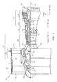
- FIG. 1 is a side cutaway illustration of a geared turbine engine 10.
- This turbine engine 10 extends along an axial centerline 12 between an upstream airflow inlet 14 and a downstream airflow exhaust 16.
- the turbine engine 10 includes a fan section 18, a compressor section 19, a combustor section 20 and a turbine section 21.
- the compressor section 19 includes a low pressure compressor (LPC) section 19A and a high pressure compressor (HPC) section 19B.
- the turbine section 21 includes a high pressure turbine (HPT) section 21A and a low pressure turbine (LPT) section 21B.
- the engine sections 18-21 are arranged sequentially along the centerline 12 within an engine housing 22.
- Each of the engine sections 18-19B, 21A and 21B includes a respective rotor 24-28.
- Each of these rotors 24-28 includes a plurality of rotor blades arranged circumferentially around and connected to one or more respective rotor disks.
- the rotor blades may be formed integral with or mechanically fastened, welded, brazed, adhered and/or otherwise attached to the respective rotor disk(s).
- the fan rotor 24 is connected to a gear train 30, for example, through a fan shaft 32.
- the gear train 30 and the LPC rotor 25 are connected to and driven by the LPT rotor 28 through a low speed shaft 33.
- the HPC rotor 26 is connected to and driven by the HPT rotor 27 through a high speed shaft 34.
- the shafts 32-34 are rotatably supported by a plurality of bearings 36; e.g., rolling element and/or thrust bearings. Each of these bearings 36 is connected to the engine housing 22 by at least one stationary structure such as, for example, an annular support strut.
- the air within the core gas path 38 may be referred to as "core air”.
- the air within the bypass gas path 40 may be referred to as "bypass air”.
- the core air is directed through the engine sections 19-21, and exits the turbine engine 10 through the airflow exhaust 16 to provide forward engine thrust.
- fuel is injected into a combustion chamber 42 and mixed with compressed core air. This fuel-core air mixture is ignited to power the turbine engine 10.
- the bypass air is directed through the bypass gas path 40 and out of the turbine engine 10 through a bypass nozzle 44 to provide additional forward engine thrust. This additional forward engine thrust may account for a majority (e.g., more than 70 percent) of total engine thrust.
- at least some of the bypass air may be directed out of the turbine engine 10 through a thrust reverser to provide reverse engine thrust.
- FIG. 1 represents one possible configuration for a geared turbine engine 10. Aspects of the disclosure may be applied in connection with other environments, including additional configurations for engines. Aspects of the disclosure may be applied in the context of a non-geared engine.
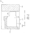
- the system 300 may interface rotating structure 206 (e.g., a rotatable seal runner) and static structure 312 in forming a seal.
- the system 300 may be used as part of an engine, such as for example the engine 10 of FIG. 1 .
- the static structure 312 may include a sealing member 224 (e.g., a carbon segment) with a nose 226.
- the sealing member 224 may be supported by a carrier 318.
- the carrier 318 may include/be made of one or more materials.
- the carrier 318 may include iron or nickel in some embodiments.
- the carrier 318 may be coupled to a tab 338.
- the tab 338 may project from the carrier 318 in a direction towards the rotating structure 206. As shown in FIG. 3 , the tab 338 may project from the carrier 318 in substantially the same direction (illustratively, axially aft) as the projection of the nose 226 (from the body of the sealing member 224) towards the rotating structure 206. At least initially, the tab 338 may not contact the rotating structure 206.
- the tab 338 may be an integral extension of the carrier 318.
- the carrier 318 may be manufactured (e.g., machined, cast, etc.) to include the tab 338.
- the tab 338 may be a separate member/element from the carrier 318 that may be attached to the carrier 318. In such embodiments, the tab 338 may be attached to the carrier, for example, via one or more of welding, brazing, a mechanical fastener (e.g., a rivet), etc.
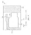
- the nose 226 shown in FIG. 3 may wear.
- a nose 226' is shown.
- the nose 226' corresponds to the nose 226 following a partial wear of the nose 226.
- the (axial) length of the nose 226' may be less than the (axial) length of the nose 226, with the difference in length being attributable to the wear that is incurred by the nose 226.
- the rotating structure 206 may share an interface 352 with the (axially aft-most edge of the) tab 338.
- the rotating structure 206 may contact the tab 338.
- Further operation of the engine (beyond the state/condition shown in FIG. 3A ) may cause the tab 338 to wear.
- further operation of the engine may cause, e.g., chips of the tab 338 to be generated at the interface 352. These chips/portions (represented by arrow 368) may be liberated from the tab 338.
- a sensor/detection device 358 may be configured to detect the presence of the worn material/chips 368 of the tab 338 (potentially in an amount greater than a threshold, where the threshold may be selected to avoid nuisance indications).
- the details of sensor/detection devices 358 of a type that may be used would be known to one of skill in the art; as such, a description of the same is omitted herein for the sake of brevity.
- the tab 338 may serve as a sacrificial wear member by providing an indication that the sealing member 224 (e.g., the nose 226) has incurred wear in an amount that is greater than a threshold.
- the tab 338 may be sized/dimensioned to provide an indication that the nose 226 is approximately 80%-90% worn (e.g., that the nose 226' is 10%-20% the size/dimension of the nose 226).
- the wear may be expressed in accordance with a dimension (e.g., length), a mass, etc.
- Knowing that the nose 226 is worn by the threshold amount may provide an early-warning indication that a maintenance activity should be (re-)scheduled, potentially to an earlier date/time than is customary.
- the indication provided by the detection device 358 may be used to schedule and prioritize when the engine will be taken out of service for maintenance based on the wear incurred by the sealing member 224.
- the particular size/dimension of the tab 338 may be based on one or more parameters, such as for example a size (e.g., a diameter) of the seal, a detection resolution/capability of the detection device 358, etc.
- the tab 338 may be segmented; the segments may be installed at various discrete locations of the carrier 318 around the circumference of the engine centerline.
- the tab 338 may be formed from the same material as the carrier 318. In some embodiments, the tab 338 may be formed from a different material than the carrier 318. Using different materials for the tab 338 and the carrier 318 may provide the detection device 358 with an ability to distinguish between the tab 338 and the carrier 318.
- At least a portion of the sealing system 300 may be duplicated a number of times on an engine.
- the sealing provided by the system 300 may be replicated as part of a larger oil system of the engine.
- a common detection device 358 may be used.
- a first instance 400a (with first sealing member 224a, first carrier 318a, and first tab 338a) and a second instance 400b (with second sealing member 224b, second carrier 318b, and second tab 338b) that each incorporate portions of the system 300 are shown. Any rotating structure that may be included is omitted from FIG. 4 for the sake of ease in illustration.
- any sacrificial/worn portions of the tabs 338a and 338b may merge/collect with one another in a common return line/channel 458 before being provided to the detection device 358.
- the first tab 338a may be made of a first material (e.g., iron) and the second tab 338b may be made of a second material (e.g., nickel) that is different from the first material.
- the detection device 358 may distinguish whether material collected by the detection device 358 is sourced from the first tab 338a or the second tab 338b. In this way, the detection device 358 may provide an indication that identifies which of the two sealing members 224a and 224b is worn beyond a threshold.
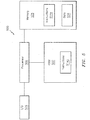
- FIG. 5 a computing system 500 that may be used in some embodiments is shown.
- the system 500 may be incorporated as part of another system, apparatus, component, etc.
- aspects of the system 500 may be included as part of one or more of the systems 300/300' or instances 400a and 400b.
- Aspects of the system 500 may be included as part of the detection device 358 (see, e.g., FIGS. 3 , 3A , and 4 )
- the system 500 may include a processor 502 and a memory 508.
- the memory 508 may store instructions (e.g., instructions 514a) that, when executed by the processor 502, may cause the system 500 to perform one or more methodological acts, such as one or more of the acts described herein. At least a portion of the instructions (e.g., instructions 514b) may be stored on a computer-readable medium (CRM) 520, such as for example a non-transitory CRM.
- CRM computer-readable medium
- the instructions 514b of the CRM 520 may be used as an alternative to, or in addition to, the use of the instructions 514a of the memory 508.
- One or both of the memory 508 and the CRM 520, taken individually or collectively, may be referred to as a storage device. Much like the CRM 520, the storage device may be non-transitory in nature.
- the system 500 may include one or more input/output (I/O) devices 526.
- the I/O devices 526 may provide an interface between the system 500 and one or more other components or devices.
- the I/O devices 526 may include one or more of a graphical user interface (GUI), a display screen, a touchscreen, a keyboard, a mouse, a joystick, a pushbutton, a microphone, a speaker, a transceiver, a sensor (e.g., a chip collector/detector), etc.
- GUI graphical user interface
- the I/O devices 526 may be used to output data in one or more formats (e.g., a visual or audio rendering).
- the memory 508 may store data 534.
- the data 534 may include an identification of a material of a component (e.g., a material of a sealing member, a carrier, a tab, etc.) and/or a mapping of a material to an instance of the component.
- the data 534 may be remotely located from, e.g., the processor 502 and may be accessible via one or more networks, communication channels, etc.
- system 500 is illustrative. One skilled in the art will appreciate, based on a review of this disclosure, that system 500 may be implemented using hardware, software, firmware, or any combination thereof.
- Some of the examples described herein relate to gas turbine applications. Aspects of the disclosure (e.g., wear tabs) may be used with mechanical systems that include rotating seals. Some embodiments may include a periodic or active monitoring of debris in a lubrication system.
Landscapes
- Engineering & Computer Science (AREA)
- General Engineering & Computer Science (AREA)
- Mechanical Engineering (AREA)
- Sealing Devices (AREA)
- Sealing Using Fluids, Sealing Without Contact, And Removal Of Oil (AREA)
- Mechanical Sealing (AREA)
Abstract
Description
- Gas turbine engines, such as those which power aircraft and industrial equipment, employ a compressor to compress air that is drawn into the engine and a turbine to capture energy associated with the combustion of a fuel-air mixture. An engine frequently includes one or more seals. Seals are used to isolate one or more regions of the engine. Seals help to ensure stable and efficient operation of the engine.
- Referring to
FIG. 2 , asealing system 200 is shown. Thesystem 200interfaces rotating structure 206 andstatic structure 212 in forming the seal. The rotatingstructure 206 is frequently referred to, or may include, a rotatable seal land/runner. As the details of the rotatingstructure 206 are known to one skilled in the art, a further description of therotating structure 206 is omitted herein for the sake of brevity. - The
static structure 212 includes acarrier 218 and a sealingmember 224. The sealingmember 224 is frequently implemented as one or more carbon segments. Thecarrier 218 supports the sealingmember 224. Thecarrier 218 is typically made of a metal or metal alloy. Thecarrier 218 may include iron or nickel. - When installed on an engine, a
nose 226 of the sealingmember 224 extends (e.g., axially extends) from abase 228 of the sealingmember 224 towards therotating structure 206 such that thenose 226 interfaces to therotating structure 206. Thenose 226 wears during engine operation/use. For example, thenose 226 wears based on thenose 226 rubbing with/abutting the rotatingstructure 206. - In many instances, the engine may be scheduled for maintenance/inspection prior to the
nose 226 being completely worn. For example, 50% of the material (e.g., 50% of a span) of thenose 226 may wear along, e.g., the superimposed axial direction between (scheduled) engine maintenance activities/procedures. A first instance of the sealingmember 224 may be discarded of and a second instance of the sealingmember 224 may be installed in place of the first instance of the sealingmember 224 during such a procedure. However, in some instances thenose 226 may incur excessive wear, such that thenose 226 may be substantially completely worn prior to a next scheduled engine maintenance/inspection procedure. - When the
nose 226 is (substantially) completely worn, therotating structure 206 shares aninterface 252 with the carrier 218 (see the system 200' ofFIG. 2A ). Portions of thecarrier 218 at theinterface 252 may begin to wear next due to the contact between thecarrier 218 and therotating structure 206. Those portions of thecarrier 218 that wear and are liberated from thecarrier 218 are collected by a collection/detection device 258. Thedetection device 258 provides an indication of when the metal material of thecarrier 218 is collected by thedetection device 258. - As the seal/sealing system is not designed to operate in the state/condition shown in
FIG. 2A (e.g., the seal is not designed to operate with thenose 226 ofFIG. 2 being (substantially) completely worn), when thedetection device 258 indicates the presence of collected material of thecarrier 218, the engine might only be allowed to operate for a very short time duration (e.g., a few hours) before the sealingmember 224 needs to be replaced. This unscheduled/unexpected, sealingmember 224 replacement activity represents a significant cost in terms of the removal of the engine from service. - The following presents a simplified summary in order to provide a basic understanding of some aspects of the disclosure. The summary is not an extensive overview of the disclosure. It is neither intended to identify key or critical elements of the disclosure nor to delineate the scope of the disclosure. The following summary merely presents some concepts of the disclosure in a simplified form as a prelude to the description below.
- Aspects of the disclosure are directed to a system comprising: a rotatable seal runner, a stationary sealing member that includes a base and a nose that extends from the base in an axial direction and interfaces with the seal runner, a carrier that supports the sealing member, and a tab coupled to the carrier, where the tab extends from the carrier in the axial direction towards the seal runner. In some embodiments, when a portion of the nose is worn the tab contacts the seal runner. In some embodiments, the portion of the nose is less than an entirety of the nose. In some embodiments, the portion corresponds to between 80% and 90% of an entirety of an axial length of the nose. In some embodiments, the system further comprises a sensor that detects and indicates when a portion of the tab is liberated from a remainder of the tab in an amount that is greater than a threshold. In some embodiments, the sensor detects when the portion of the tab is liberated from the remainder of the tab based on a material of the tab. In some embodiments, the material of the tab includes at least one of iron or nickel. In some embodiments, the tab includes a first material and the carrier includes a second material. In some embodiments, the first material is different from the second material. In some embodiments, the tab is an integral extension of the carrier. In some embodiments, the tab is a separate member from the carrier. In some embodiments, the tab is attached to the carrier via one or more of a weld, a braze, or a mechanical fastener. In some embodiments, the sealing member includes a carbon segment. In some embodiments, the system further comprises a second rotatable seal runner, a stationary second sealing member that includes a second base and a second nose that extends from the second base in the axial direction and interfaces with the second seal runner, a second carrier that supports the second sealing member, and a second tab coupled to the second carrier, where the second tab extends from the second carrier in the axial direction towards the second seal runner. In some embodiments, the system further comprises a sensor that detects and indicates when a portion of the tab is liberated from a remainder of the tab in an amount that is greater than a threshold. In some embodiments, the sensor detects and indicates when a second portion of the second tab is liberated from a remainder of the second tab in an amount that is greater than a second threshold. In some embodiments, the tab includes a first material and the second tab includes a second material that is different from the first material. In some embodiments, the sensor provides an identification of the sealing member when the sensor detects the first material is present in the amount greater than the threshold, and the sensor provides an identification of the second sealing member when the sensor detects the second material is present in the amount that is greater than the second threshold.
- The present disclosure is illustrated by way of example and not limited in the accompanying figures in which like reference numerals indicate similar elements. The figures are not necessarily drawn to scale unless explicitly indicated otherwise.
-
FIG. 1 is a side cutaway illustration of a geared turbine engine. -
FIG. 2 illustrates a prior art sealing system that interfaces rotating structure and static structure. -
FIG. 2A illustrates the sealing system ofFIG. 2 in a condition/state where a nose of a sealing member is substantially completely worn. -
FIG. 3 illustrates a sealing system that interfaces rotating structure and static structure in accordance with aspects of this disclosure. -
FIG. 3A illustrates the sealing system ofFIG. 3 in a condition/state where a nose of a sealing member is fractionally worn. -
FIG. 4 illustrates two instances of a sealing system with sacrificial material from a plurality of tabs being provided to a common detection device. -
FIG. 5 illustrates a computing system in accordance with aspects of this disclosure. - It is noted that various connections are set forth between elements in the following description and in the drawings (the contents of which are included in this disclosure by way of reference). It is noted that these connections are general and, unless specified otherwise, may be direct or indirect and that this specification is not intended to be limiting in this respect. A coupling between two or more entities may refer to a direct connection or an indirect connection. An indirect connection may incorporate one or more intervening entities.
- In accordance with various aspects of the disclosure, apparatuses, systems and methods are described for detecting when a sealing member has worn in an amount greater than a threshold. In some embodiments, a carrier of the sealing member may include a tab that may project towards a rotating structure. At least a portion of the tab, which may serve as a sacrificial wear member, may be collected and detected by a detection device. This collected/detected portion may serve as an indication of the wear experienced by the sealing member.
- Aspects of the disclosure may be applied in connection with a gas turbine engine.
FIG. 1 is a side cutaway illustration of a gearedturbine engine 10. Thisturbine engine 10 extends along anaxial centerline 12 between anupstream airflow inlet 14 and adownstream airflow exhaust 16. Theturbine engine 10 includes afan section 18, acompressor section 19, acombustor section 20 and aturbine section 21. Thecompressor section 19 includes a low pressure compressor (LPC)section 19A and a high pressure compressor (HPC)section 19B. Theturbine section 21 includes a high pressure turbine (HPT)section 21A and a low pressure turbine (LPT)section 21B. - The engine sections 18-21 are arranged sequentially along the
centerline 12 within anengine housing 22. Each of the engine sections 18-19B, 21A and 21B includes a respective rotor 24-28. Each of these rotors 24-28 includes a plurality of rotor blades arranged circumferentially around and connected to one or more respective rotor disks. The rotor blades, for example, may be formed integral with or mechanically fastened, welded, brazed, adhered and/or otherwise attached to the respective rotor disk(s). - The
fan rotor 24 is connected to agear train 30, for example, through afan shaft 32. Thegear train 30 and theLPC rotor 25 are connected to and driven by theLPT rotor 28 through alow speed shaft 33. TheHPC rotor 26 is connected to and driven by theHPT rotor 27 through ahigh speed shaft 34. The shafts 32-34 are rotatably supported by a plurality ofbearings 36; e.g., rolling element and/or thrust bearings. Each of thesebearings 36 is connected to theengine housing 22 by at least one stationary structure such as, for example, an annular support strut. - During operation, air enters the
turbine engine 10 through theairflow inlet 14, and is directed through thefan section 18 and into acore gas path 38 and abypass gas path 40. The air within thecore gas path 38 may be referred to as "core air". The air within thebypass gas path 40 may be referred to as "bypass air". The core air is directed through the engine sections 19-21, and exits theturbine engine 10 through theairflow exhaust 16 to provide forward engine thrust. Within thecombustor section 20, fuel is injected into acombustion chamber 42 and mixed with compressed core air. This fuel-core air mixture is ignited to power theturbine engine 10. The bypass air is directed through thebypass gas path 40 and out of theturbine engine 10 through abypass nozzle 44 to provide additional forward engine thrust. This additional forward engine thrust may account for a majority (e.g., more than 70 percent) of total engine thrust. Alternatively, at least some of the bypass air may be directed out of theturbine engine 10 through a thrust reverser to provide reverse engine thrust. -
FIG. 1 represents one possible configuration for a gearedturbine engine 10. Aspects of the disclosure may be applied in connection with other environments, including additional configurations for engines. Aspects of the disclosure may be applied in the context of a non-geared engine. - Referring now to
FIG. 3 , asystem 300 is shown. Thesystem 300 may interface rotating structure 206 (e.g., a rotatable seal runner) andstatic structure 312 in forming a seal. Thesystem 300 may be used as part of an engine, such as for example theengine 10 ofFIG. 1 . - The
static structure 312 may include a sealing member 224 (e.g., a carbon segment) with anose 226. The sealingmember 224 may be supported by acarrier 318. Thecarrier 318 may include/be made of one or more materials. For example, thecarrier 318 may include iron or nickel in some embodiments. - The
carrier 318 may be coupled to atab 338. Thetab 338 may project from thecarrier 318 in a direction towards the rotatingstructure 206. As shown inFIG. 3 , thetab 338 may project from thecarrier 318 in substantially the same direction (illustratively, axially aft) as the projection of the nose 226 (from the body of the sealing member 224) towards the rotatingstructure 206. At least initially, thetab 338 may not contact therotating structure 206. - In some embodiments, the
tab 338 may be an integral extension of thecarrier 318. In such embodiments, thecarrier 318 may be manufactured (e.g., machined, cast, etc.) to include thetab 338. - In some embodiments, the
tab 338 may be a separate member/element from thecarrier 318 that may be attached to thecarrier 318. In such embodiments, thetab 338 may be attached to the carrier, for example, via one or more of welding, brazing, a mechanical fastener (e.g., a rivet), etc. - During the operation of the engine on which the
sealing system 300 is installed, thenose 226 shown inFIG. 3 may wear. For example, and referring toFIG. 3A , a nose 226' is shown. The nose 226' corresponds to thenose 226 following a partial wear of thenose 226. The (axial) length of the nose 226' may be less than the (axial) length of thenose 226, with the difference in length being attributable to the wear that is incurred by thenose 226. - Once the
nose 226 has worn to the point shown inFIG. 3A , the rotatingstructure 206 may share aninterface 352 with the (axially aft-most edge of the)tab 338. For example, the rotatingstructure 206 may contact thetab 338. Further operation of the engine (beyond the state/condition shown inFIG. 3A ) may cause thetab 338 to wear. For example, further operation of the engine may cause, e.g., chips of thetab 338 to be generated at theinterface 352. These chips/portions (represented by arrow 368) may be liberated from thetab 338. A sensor/detection device 358 may be configured to detect the presence of the worn material/chips 368 of the tab 338 (potentially in an amount greater than a threshold, where the threshold may be selected to avoid nuisance indications). The details of sensor/detection devices 358 of a type that may be used would be known to one of skill in the art; as such, a description of the same is omitted herein for the sake of brevity. - In accordance with the above, the
tab 338 may serve as a sacrificial wear member by providing an indication that the sealing member 224 (e.g., the nose 226) has incurred wear in an amount that is greater than a threshold. For example, in some embodiments thetab 338 may be sized/dimensioned to provide an indication that thenose 226 is approximately 80%-90% worn (e.g., that the nose 226' is 10%-20% the size/dimension of the nose 226). The wear may be expressed in accordance with a dimension (e.g., length), a mass, etc. Knowing that thenose 226 is worn by the threshold amount may provide an early-warning indication that a maintenance activity should be (re-)scheduled, potentially to an earlier date/time than is customary. The indication provided by thedetection device 358 may be used to schedule and prioritize when the engine will be taken out of service for maintenance based on the wear incurred by the sealingmember 224. - The particular size/dimension of the
tab 338 may be based on one or more parameters, such as for example a size (e.g., a diameter) of the seal, a detection resolution/capability of thedetection device 358, etc. In some embodiments, thetab 338 may be segmented; the segments may be installed at various discrete locations of thecarrier 318 around the circumference of the engine centerline. - In some embodiments, the
tab 338 may be formed from the same material as thecarrier 318. In some embodiments, thetab 338 may be formed from a different material than thecarrier 318. Using different materials for thetab 338 and thecarrier 318 may provide thedetection device 358 with an ability to distinguish between thetab 338 and thecarrier 318. - At least a portion of the
sealing system 300 may be duplicated a number of times on an engine. For example, the sealing provided by thesystem 300 may be replicated as part of a larger oil system of the engine. However, acommon detection device 358 may be used. For example, and referring toFIG. 4 , afirst instance 400a (with first sealingmember 224a,first carrier 318a, andfirst tab 338a) and asecond instance 400b (with second sealingmember 224b,second carrier 318b, andsecond tab 338b) that each incorporate portions of thesystem 300 are shown. Any rotating structure that may be included is omitted fromFIG. 4 for the sake of ease in illustration. - Any sacrificial/worn portions of the
tabs channel 458 before being provided to thedetection device 358. In this respect, thefirst tab 338a may be made of a first material (e.g., iron) and thesecond tab 338b may be made of a second material (e.g., nickel) that is different from the first material. By using different materials for thetabs detection device 358 may distinguish whether material collected by thedetection device 358 is sourced from thefirst tab 338a or thesecond tab 338b. In this way, thedetection device 358 may provide an indication that identifies which of the two sealingmembers - Turning to
FIG. 5 , acomputing system 500 that may be used in some embodiments is shown. Thesystem 500 may be incorporated as part of another system, apparatus, component, etc. For example, aspects of thesystem 500 may be included as part of one or more of thesystems 300/300' orinstances system 500 may be included as part of the detection device 358 (see, e.g.,FIGS. 3 ,3A , and4 ) - The
system 500 may include aprocessor 502 and amemory 508. Thememory 508 may store instructions (e.g.,instructions 514a) that, when executed by theprocessor 502, may cause thesystem 500 to perform one or more methodological acts, such as one or more of the acts described herein. At least a portion of the instructions (e.g., instructions 514b) may be stored on a computer-readable medium (CRM) 520, such as for example a non-transitory CRM. The instructions 514b of theCRM 520 may be used as an alternative to, or in addition to, the use of theinstructions 514a of thememory 508. One or both of thememory 508 and theCRM 520, taken individually or collectively, may be referred to as a storage device. Much like theCRM 520, the storage device may be non-transitory in nature. - In some embodiments, the
system 500 may include one or more input/output (I/O)devices 526. The I/O devices 526 may provide an interface between thesystem 500 and one or more other components or devices. The I/O devices 526 may include one or more of a graphical user interface (GUI), a display screen, a touchscreen, a keyboard, a mouse, a joystick, a pushbutton, a microphone, a speaker, a transceiver, a sensor (e.g., a chip collector/detector), etc. The I/O devices 526 may be used to output data in one or more formats (e.g., a visual or audio rendering). - The
memory 508 may storedata 534. Thedata 534 may include an identification of a material of a component (e.g., a material of a sealing member, a carrier, a tab, etc.) and/or a mapping of a material to an instance of the component. In some embodiments, thedata 534 may be remotely located from, e.g., theprocessor 502 and may be accessible via one or more networks, communication channels, etc. - The
system 500 is illustrative. One skilled in the art will appreciate, based on a review of this disclosure, thatsystem 500 may be implemented using hardware, software, firmware, or any combination thereof. - Some of the examples described herein relate to gas turbine applications. Aspects of the disclosure (e.g., wear tabs) may be used with mechanical systems that include rotating seals. Some embodiments may include a periodic or active monitoring of debris in a lubrication system.
- Aspects of the disclosure have been described in terms of illustrative embodiments thereof. Numerous other embodiments, modifications, and variations within the scope and spirit of the appended claims will occur to persons of ordinary skill in the art from a review of this disclosure. For example, one of ordinary skill in the art will appreciate that the steps described in conjunction with the illustrative figures may be performed in other than the recited order, and that one or more steps illustrated may be optional in accordance with aspects of the disclosure. One or more features described in connection with a first embodiment may be combined with one or more features of one or more additional embodiments.
Claims (15)
- A system (300) comprising:a rotatable seal runner (206);a stationary sealing member (224) that includes a base (228) and a nose (226) that extends from the base (228) in an axial direction and interfaces with the seal runner (206);a carrier (318) that supports the sealing member (224); anda tab (338) coupled to the carrier (318),wherein the tab (338) extends from the carrier (318) in the axial direction towards the seal runner (206).
- The system (300) of claim 1, wherein when a portion of the nose (226) is worn, the tab (338) contacts the seal runner (206).
- The system (300) of claim 2, wherein the portion of the nose (226) is less than an entirety of the nose (226).
- The system (300) of claim 2 or 3, wherein the portion corresponds to between 80% and 90% of an entirety of an axial length of the nose (226).
- The system (300) of any preceding claim, wherein the tab (338) is an integral extension of the carrier (318).
- The system (300) of any of claims 1 to 4, wherein the tab (338) is a separate member from the carrier (318), and wherein, optionally, the tab (338) is attached to the carrier (318) via one or more of a weld, a braze, or a mechanical fastener.
- The system (300) of any preceding claim, wherein the sealing member (224) includes a carbon segment.
- The system (300) of any preceding claim, further comprising:a second rotatable seal runner (206);a stationary second sealing member (224) that includes a second base (228) and a second nose (226) that extends from the second base (228) in the axial direction and interfaces with the second seal runner (206);a second carrier (318) that supports the second sealing member (224); anda second tab (338) coupled to the second carrier (318),wherein the second tab (338) extends from the second carrier (318) in the axial direction towards the second seal runner (206).
- The system (300) of any preceding claim, further comprising:
a sensor (358) that detects and indicates when a portion of the tab (338) is liberated from a remainder of the tab (338) in an amount that is greater than a threshold. - The system (300) of claim 9, wherein the sensor (358) detects when the portion of the tab (338) is liberated from the remainder of the tab (338) based on a material of the tab (338).
- The system (300) of claim 10, wherein the material of the tab (338) includes at least one of iron or nickel.
- The system (300) of claim 10 or 11, wherein the tab (338) includes a first material and the carrier (318) includes a second material, and wherein, optionally, the first material is different from the second material.
- The system (300) of any of claims 9 to 12, when dependent on claim 8, wherein the sensor (358) detects and indicates when a second portion of the second tab (338) is liberated from a remainder of the second tab (338) in an amount that is greater than a second threshold.
- The system (300) of claim 13, wherein the tab (338) includes a or the first material and the second tab (338) includes a second tab material that is different from the first material.
- The system (300) of claim 14, wherein the sensor (358) provides an identification of the sealing member (224) when the sensor (358) detects the first material is present in the amount greater than the threshold, and wherein the sensor (358) provides an identification of the second sealing member (224) when the sensor (358) detects the second material is present in the amount that is greater than the second threshold.
Applications Claiming Priority (1)
| Application Number | Priority Date | Filing Date | Title |
|---|---|---|---|
| US15/667,974 US11193591B2 (en) | 2017-08-03 | 2017-08-03 | Seal sacrificial wear indicator |
Publications (2)
| Publication Number | Publication Date |
|---|---|
| EP3438418A1 true EP3438418A1 (en) | 2019-02-06 |
| EP3438418B1 EP3438418B1 (en) | 2020-04-08 |
Family
ID=63142994
Family Applications (1)
| Application Number | Title | Priority Date | Filing Date |
|---|---|---|---|
| EP18186900.9A Active EP3438418B1 (en) | 2017-08-03 | 2018-08-01 | Seal sacrificial wear indicator |
Country Status (2)
| Country | Link |
|---|---|
| US (1) | US11193591B2 (en) |
| EP (1) | EP3438418B1 (en) |
Cited By (1)
| Publication number | Priority date | Publication date | Assignee | Title |
|---|---|---|---|---|
| CN115280048A (en) * | 2020-05-11 | 2022-11-01 | 丹佛斯公司 | Floating ring seal for refrigerant compressors |
Families Citing this family (10)
| Publication number | Priority date | Publication date | Assignee | Title |
|---|---|---|---|---|
| US11112348B2 (en) * | 2019-03-26 | 2021-09-07 | Hamilton Sundstrand Corporation | Wear sensors for monitoring seal wear in bearing arrangements |
| US10969017B2 (en) | 2019-04-02 | 2021-04-06 | United Technologies Corporation | Face seal with insert |
| US11293351B2 (en) | 2020-07-16 | 2022-04-05 | Raytheon Technologies Corporation | Gas turbine engine including seal assembly with abradable coating including magnetic particles embedded in polymer |
| US11313280B2 (en) | 2020-07-16 | 2022-04-26 | Raytheon Technologies Corporation | Gas turbine engine including seal assembly with abradable coating and cutter |
| US11313281B2 (en) | 2020-07-16 | 2022-04-26 | Raytheon Technologies Corporation | Gas turbine engine including seal assembly with abradable coating including magnetic particles |
| US11454324B2 (en) | 2020-08-26 | 2022-09-27 | Raytheon Technologies Corporation | Face seal carrier arrester |
| US11401832B2 (en) | 2021-01-05 | 2022-08-02 | Raytheon Technologies Corporation | Gas turbine engine including seal plate with separable tabs |
| US11466584B1 (en) | 2021-07-29 | 2022-10-11 | Rolls-Royce Corporation | Ceramic runner seal assembly with compliant holder |
| EP4477923A4 (en) * | 2022-02-08 | 2025-08-27 | Schaeffler Technologies Ag | Sealing device |
| US12461023B2 (en) * | 2022-08-05 | 2025-11-04 | Caterpillar Inc. | Subsurface underlying incipient failure indicator in wear components |
Citations (4)
| Publication number | Priority date | Publication date | Assignee | Title |
|---|---|---|---|---|
| US3695406A (en) * | 1969-05-08 | 1972-10-03 | Abex Corp | Coupling with carbon and beryllium friction surfaces |
| GB2442490A (en) * | 2006-10-05 | 2008-04-09 | Ford Global Tech Llc | A method for determining degradation of lubricating oil |
| EP2014877A2 (en) * | 2007-07-11 | 2009-01-14 | United Technologies Corporation | Systems and methods for monitoring gas turbine engines |
| US20120267858A1 (en) * | 2011-04-25 | 2012-10-25 | Bal Seal Engineering, Inc. | Seal failure detection systems and related methods |
Family Cites Families (24)
| Publication number | Priority date | Publication date | Assignee | Title |
|---|---|---|---|---|
| US2937039A (en) * | 1957-05-29 | 1960-05-17 | Chicago Rawhide Mfg Co | Controlled gap seal |
| US3632117A (en) * | 1969-05-15 | 1972-01-04 | Westinghouse Electric Corp | Seal lift-off mechanism |
| US4036505A (en) * | 1973-12-06 | 1977-07-19 | The Wickes Corporation | Mechanical seals |
| US4174844A (en) * | 1975-12-05 | 1979-11-20 | Crane Packing Company | Mechanical seal |
| FI64448C (en) | 1982-02-09 | 1983-11-10 | Safematic Ltd Oy | ENCLOSURE REQUIREMENTS |
| GB8319550D0 (en) * | 1983-07-20 | 1983-08-24 | Grange Packing Ltd | Seal wear indicator |
| US5017022A (en) * | 1988-11-09 | 1991-05-21 | Allied-Signal, Inc. | High temperature bearing |
| US5014999A (en) * | 1989-03-06 | 1991-05-14 | Car-Graph, Inc. | Pressure enhanced self aligning seal |
| WO1997026475A1 (en) * | 1996-01-19 | 1997-07-24 | Alliedsignal Inc. | Circumferential seal with ceramic rotor |
| WO1997031206A1 (en) * | 1996-02-23 | 1997-08-28 | Tomoichiro Iwane | Mechanical seal |
| US6360610B1 (en) * | 1999-11-02 | 2002-03-26 | Jacek Jarzynski | Condition monitoring system and method for an interface |
| DE202007016406U1 (en) * | 2007-11-23 | 2008-01-31 | Burgmann Industries Gmbh & Co. Kg | Device for rotational securing of an axially movably held on a mounting member slide ring of a mechanical seal assembly |
| DE202007016407U1 (en) * | 2007-11-23 | 2008-01-31 | Burgmann Industries Gmbh & Co. Kg | The mechanical seal assembly |
| US7905495B2 (en) * | 2007-11-29 | 2011-03-15 | Rolls-Royce Corporation | Circumferential sealing arrangement |
| DE202008009842U1 (en) * | 2008-07-22 | 2008-09-18 | Burgmann Industries Gmbh & Co. Kg | Mechanical seal arrangement with filter element |
| US8205891B2 (en) * | 2008-09-15 | 2012-06-26 | Stein Seal Company | Intershaft seal assembly |
| US8527214B2 (en) * | 2008-10-26 | 2013-09-03 | Michael N. Horak | System and method for monitoring mechanical seals |
| DE202009010044U1 (en) * | 2009-07-23 | 2009-09-24 | Burgmann Industries Gmbh & Co. Kg | Mechanical seal with compensation element |
| US8864446B2 (en) * | 2011-05-23 | 2014-10-21 | Siemens Energy, Inc. | Wear pin gap closure detection system for gas turbine engine |
| US9309975B2 (en) * | 2012-04-26 | 2016-04-12 | Pratt & Whitney Canada Corp. | Thermally response controlled gap seal device |
| DE102012215887A1 (en) * | 2012-09-07 | 2014-05-15 | Siemens Aktiengesellschaft | Arrangement with a gas seal |
| US20140265151A1 (en) * | 2013-03-15 | 2014-09-18 | Stein Seal Company | Circumferential Seal with Ceramic Runner |
| GB2516119B (en) | 2013-08-06 | 2015-06-24 | Messier Dowty Ltd | An Apparatus Comprising a Sealing Element |
| US10174845B2 (en) * | 2016-02-16 | 2019-01-08 | Rolls-Royce Corporation | Ceramic seal runner and mount for a rotating shaft |
-
2017
- 2017-08-03 US US15/667,974 patent/US11193591B2/en active Active
-
2018
- 2018-08-01 EP EP18186900.9A patent/EP3438418B1/en active Active
Patent Citations (4)
| Publication number | Priority date | Publication date | Assignee | Title |
|---|---|---|---|---|
| US3695406A (en) * | 1969-05-08 | 1972-10-03 | Abex Corp | Coupling with carbon and beryllium friction surfaces |
| GB2442490A (en) * | 2006-10-05 | 2008-04-09 | Ford Global Tech Llc | A method for determining degradation of lubricating oil |
| EP2014877A2 (en) * | 2007-07-11 | 2009-01-14 | United Technologies Corporation | Systems and methods for monitoring gas turbine engines |
| US20120267858A1 (en) * | 2011-04-25 | 2012-10-25 | Bal Seal Engineering, Inc. | Seal failure detection systems and related methods |
Cited By (1)
| Publication number | Priority date | Publication date | Assignee | Title |
|---|---|---|---|---|
| CN115280048A (en) * | 2020-05-11 | 2022-11-01 | 丹佛斯公司 | Floating ring seal for refrigerant compressors |
Also Published As
| Publication number | Publication date |
|---|---|
| EP3438418B1 (en) | 2020-04-08 |
| US11193591B2 (en) | 2021-12-07 |
| US20190040959A1 (en) | 2019-02-07 |
Similar Documents
| Publication | Publication Date | Title |
|---|---|---|
| EP3438418B1 (en) | Seal sacrificial wear indicator | |
| EP3453843B1 (en) | Sealing assembly for a bearing compartment comprising an arrangement for measuring rotational velocity | |
| US10370996B2 (en) | Floating, non-contact seal with offset build clearance for load imbalance | |
| US10487943B2 (en) | Multi-ply seal ring | |
| US10550708B2 (en) | Floating, non-contact seal with at least three beams | |
| EP4234989B1 (en) | Translating fluid coupling device | |
| EP2852741B1 (en) | Gas turbine engine with debris discourager | |
| US10513938B2 (en) | Intershaft compartment buffering arrangement | |
| EP3254764A1 (en) | Nozzle for delivering fluid to a component | |
| US11371441B2 (en) | Translating fluid delivery device | |
| EP3409885B1 (en) | Deflection spring seal | |
| US12486778B2 (en) | Seal monitoring apparatus | |
| US20180291755A1 (en) | Insulated seal seat | |
| EP3904730B1 (en) | Retainer for securing a seal element to a seal carrier | |
| EP3904732B1 (en) | Rotational equipment seal element with internal fluid passage | |
| US11313280B2 (en) | Gas turbine engine including seal assembly with abradable coating and cutter | |
| US11493135B2 (en) | Non-contact seal with axial engagement | |
| US10612409B2 (en) | Active clearance control collector to manifold insert | |
| US12297740B2 (en) | Seal carrier with rolling element guide rail contact | |
| US12180841B2 (en) | Seal element bonded to seal carrier for a turbine engine | |
| EP3309364A2 (en) | System of an engine and corresponding apparatus |
Legal Events
| Date | Code | Title | Description |
|---|---|---|---|
| PUAI | Public reference made under article 153(3) epc to a published international application that has entered the european phase |
Free format text: ORIGINAL CODE: 0009012 |
|
| STAA | Information on the status of an ep patent application or granted ep patent |
Free format text: STATUS: THE APPLICATION HAS BEEN PUBLISHED |
|
| AK | Designated contracting states |
Kind code of ref document: A1 Designated state(s): AL AT BE BG CH CY CZ DE DK EE ES FI FR GB GR HR HU IE IS IT LI LT LU LV MC MK MT NL NO PL PT RO RS SE SI SK SM TR |
|
| AX | Request for extension of the european patent |
Extension state: BA ME |
|
| STAA | Information on the status of an ep patent application or granted ep patent |
Free format text: STATUS: REQUEST FOR EXAMINATION WAS MADE |
|
| 17P | Request for examination filed |
Effective date: 20190806 |
|
| RBV | Designated contracting states (corrected) |
Designated state(s): AL AT BE BG CH CY CZ DE DK EE ES FI FR GB GR HR HU IE IS IT LI LT LU LV MC MK MT NL NO PL PT RO RS SE SI SK SM TR |
|
| GRAP | Despatch of communication of intention to grant a patent |
Free format text: ORIGINAL CODE: EPIDOSNIGR1 |
|
| STAA | Information on the status of an ep patent application or granted ep patent |
Free format text: STATUS: GRANT OF PATENT IS INTENDED |
|
| INTG | Intention to grant announced |
Effective date: 20191023 |
|
| GRAS | Grant fee paid |
Free format text: ORIGINAL CODE: EPIDOSNIGR3 |
|
| GRAA | (expected) grant |
Free format text: ORIGINAL CODE: 0009210 |
|
| STAA | Information on the status of an ep patent application or granted ep patent |
Free format text: STATUS: THE PATENT HAS BEEN GRANTED |
|
| AK | Designated contracting states |
Kind code of ref document: B1 Designated state(s): AL AT BE BG CH CY CZ DE DK EE ES FI FR GB GR HR HU IE IS IT LI LT LU LV MC MK MT NL NO PL PT RO RS SE SI SK SM TR |
|
| REG | Reference to a national code |
Ref country code: CH Ref legal event code: EP Ref country code: AT Ref legal event code: REF Ref document number: 1254655 Country of ref document: AT Kind code of ref document: T Effective date: 20200415 |
|
| REG | Reference to a national code |
Ref country code: DE Ref legal event code: R096 Ref document number: 602018003598 Country of ref document: DE |
|
| REG | Reference to a national code |
Ref country code: IE Ref legal event code: FG4D |
|
| REG | Reference to a national code |
Ref country code: NL Ref legal event code: MP Effective date: 20200408 |
|
| REG | Reference to a national code |
Ref country code: LT Ref legal event code: MG4D |
|
| PG25 | Lapsed in a contracting state [announced via postgrant information from national office to epo] |
Ref country code: PT Free format text: LAPSE BECAUSE OF FAILURE TO SUBMIT A TRANSLATION OF THE DESCRIPTION OR TO PAY THE FEE WITHIN THE PRESCRIBED TIME-LIMIT Effective date: 20200817 Ref country code: SE Free format text: LAPSE BECAUSE OF FAILURE TO SUBMIT A TRANSLATION OF THE DESCRIPTION OR TO PAY THE FEE WITHIN THE PRESCRIBED TIME-LIMIT Effective date: 20200408 Ref country code: NO Free format text: LAPSE BECAUSE OF FAILURE TO SUBMIT A TRANSLATION OF THE DESCRIPTION OR TO PAY THE FEE WITHIN THE PRESCRIBED TIME-LIMIT Effective date: 20200708 Ref country code: IS Free format text: LAPSE BECAUSE OF FAILURE TO SUBMIT A TRANSLATION OF THE DESCRIPTION OR TO PAY THE FEE WITHIN THE PRESCRIBED TIME-LIMIT Effective date: 20200808 Ref country code: GR Free format text: LAPSE BECAUSE OF FAILURE TO SUBMIT A TRANSLATION OF THE DESCRIPTION OR TO PAY THE FEE WITHIN THE PRESCRIBED TIME-LIMIT Effective date: 20200709 Ref country code: LT Free format text: LAPSE BECAUSE OF FAILURE TO SUBMIT A TRANSLATION OF THE DESCRIPTION OR TO PAY THE FEE WITHIN THE PRESCRIBED TIME-LIMIT Effective date: 20200408 Ref country code: NL Free format text: LAPSE BECAUSE OF FAILURE TO SUBMIT A TRANSLATION OF THE DESCRIPTION OR TO PAY THE FEE WITHIN THE PRESCRIBED TIME-LIMIT Effective date: 20200408 Ref country code: FI Free format text: LAPSE BECAUSE OF FAILURE TO SUBMIT A TRANSLATION OF THE DESCRIPTION OR TO PAY THE FEE WITHIN THE PRESCRIBED TIME-LIMIT Effective date: 20200408 |
|
| REG | Reference to a national code |
Ref country code: AT Ref legal event code: MK05 Ref document number: 1254655 Country of ref document: AT Kind code of ref document: T Effective date: 20200408 |
|
| PG25 | Lapsed in a contracting state [announced via postgrant information from national office to epo] |
Ref country code: LV Free format text: LAPSE BECAUSE OF FAILURE TO SUBMIT A TRANSLATION OF THE DESCRIPTION OR TO PAY THE FEE WITHIN THE PRESCRIBED TIME-LIMIT Effective date: 20200408 Ref country code: HR Free format text: LAPSE BECAUSE OF FAILURE TO SUBMIT A TRANSLATION OF THE DESCRIPTION OR TO PAY THE FEE WITHIN THE PRESCRIBED TIME-LIMIT Effective date: 20200408 Ref country code: RS Free format text: LAPSE BECAUSE OF FAILURE TO SUBMIT A TRANSLATION OF THE DESCRIPTION OR TO PAY THE FEE WITHIN THE PRESCRIBED TIME-LIMIT Effective date: 20200408 Ref country code: BG Free format text: LAPSE BECAUSE OF FAILURE TO SUBMIT A TRANSLATION OF THE DESCRIPTION OR TO PAY THE FEE WITHIN THE PRESCRIBED TIME-LIMIT Effective date: 20200708 |
|
| PG25 | Lapsed in a contracting state [announced via postgrant information from national office to epo] |
Ref country code: AL Free format text: LAPSE BECAUSE OF FAILURE TO SUBMIT A TRANSLATION OF THE DESCRIPTION OR TO PAY THE FEE WITHIN THE PRESCRIBED TIME-LIMIT Effective date: 20200408 |
|
| REG | Reference to a national code |
Ref country code: DE Ref legal event code: R097 Ref document number: 602018003598 Country of ref document: DE |
|
| PG25 | Lapsed in a contracting state [announced via postgrant information from national office to epo] |
Ref country code: EE Free format text: LAPSE BECAUSE OF FAILURE TO SUBMIT A TRANSLATION OF THE DESCRIPTION OR TO PAY THE FEE WITHIN THE PRESCRIBED TIME-LIMIT Effective date: 20200408 Ref country code: SM Free format text: LAPSE BECAUSE OF FAILURE TO SUBMIT A TRANSLATION OF THE DESCRIPTION OR TO PAY THE FEE WITHIN THE PRESCRIBED TIME-LIMIT Effective date: 20200408 Ref country code: DK Free format text: LAPSE BECAUSE OF FAILURE TO SUBMIT A TRANSLATION OF THE DESCRIPTION OR TO PAY THE FEE WITHIN THE PRESCRIBED TIME-LIMIT Effective date: 20200408 Ref country code: CZ Free format text: LAPSE BECAUSE OF FAILURE TO SUBMIT A TRANSLATION OF THE DESCRIPTION OR TO PAY THE FEE WITHIN THE PRESCRIBED TIME-LIMIT Effective date: 20200408 Ref country code: ES Free format text: LAPSE BECAUSE OF FAILURE TO SUBMIT A TRANSLATION OF THE DESCRIPTION OR TO PAY THE FEE WITHIN THE PRESCRIBED TIME-LIMIT Effective date: 20200408 Ref country code: IT Free format text: LAPSE BECAUSE OF FAILURE TO SUBMIT A TRANSLATION OF THE DESCRIPTION OR TO PAY THE FEE WITHIN THE PRESCRIBED TIME-LIMIT Effective date: 20200408 Ref country code: RO Free format text: LAPSE BECAUSE OF FAILURE TO SUBMIT A TRANSLATION OF THE DESCRIPTION OR TO PAY THE FEE WITHIN THE PRESCRIBED TIME-LIMIT Effective date: 20200408 Ref country code: AT Free format text: LAPSE BECAUSE OF FAILURE TO SUBMIT A TRANSLATION OF THE DESCRIPTION OR TO PAY THE FEE WITHIN THE PRESCRIBED TIME-LIMIT Effective date: 20200408 |
|
| PLBE | No opposition filed within time limit |
Free format text: ORIGINAL CODE: 0009261 |
|
| STAA | Information on the status of an ep patent application or granted ep patent |
Free format text: STATUS: NO OPPOSITION FILED WITHIN TIME LIMIT |
|
| PG25 | Lapsed in a contracting state [announced via postgrant information from national office to epo] |
Ref country code: PL Free format text: LAPSE BECAUSE OF FAILURE TO SUBMIT A TRANSLATION OF THE DESCRIPTION OR TO PAY THE FEE WITHIN THE PRESCRIBED TIME-LIMIT Effective date: 20200408 Ref country code: SK Free format text: LAPSE BECAUSE OF FAILURE TO SUBMIT A TRANSLATION OF THE DESCRIPTION OR TO PAY THE FEE WITHIN THE PRESCRIBED TIME-LIMIT Effective date: 20200408 |
|
| 26N | No opposition filed |
Effective date: 20210112 |
|
| PG25 | Lapsed in a contracting state [announced via postgrant information from national office to epo] |
Ref country code: MC Free format text: LAPSE BECAUSE OF FAILURE TO SUBMIT A TRANSLATION OF THE DESCRIPTION OR TO PAY THE FEE WITHIN THE PRESCRIBED TIME-LIMIT Effective date: 20200408 |
|
| PG25 | Lapsed in a contracting state [announced via postgrant information from national office to epo] |
Ref country code: LU Free format text: LAPSE BECAUSE OF NON-PAYMENT OF DUE FEES Effective date: 20200801 |
|
| REG | Reference to a national code |
Ref country code: BE Ref legal event code: MM Effective date: 20200831 |
|
| PG25 | Lapsed in a contracting state [announced via postgrant information from national office to epo] |
Ref country code: SI Free format text: LAPSE BECAUSE OF FAILURE TO SUBMIT A TRANSLATION OF THE DESCRIPTION OR TO PAY THE FEE WITHIN THE PRESCRIBED TIME-LIMIT Effective date: 20200408 |
|
| PG25 | Lapsed in a contracting state [announced via postgrant information from national office to epo] |
Ref country code: BE Free format text: LAPSE BECAUSE OF NON-PAYMENT OF DUE FEES Effective date: 20200831 Ref country code: IE Free format text: LAPSE BECAUSE OF NON-PAYMENT OF DUE FEES Effective date: 20200801 |
|
| REG | Reference to a national code |
Ref country code: CH Ref legal event code: PL |
|
| PG25 | Lapsed in a contracting state [announced via postgrant information from national office to epo] |
Ref country code: LI Free format text: LAPSE BECAUSE OF NON-PAYMENT OF DUE FEES Effective date: 20210831 Ref country code: CH Free format text: LAPSE BECAUSE OF NON-PAYMENT OF DUE FEES Effective date: 20210831 |
|
| PG25 | Lapsed in a contracting state [announced via postgrant information from national office to epo] |
Ref country code: TR Free format text: LAPSE BECAUSE OF FAILURE TO SUBMIT A TRANSLATION OF THE DESCRIPTION OR TO PAY THE FEE WITHIN THE PRESCRIBED TIME-LIMIT Effective date: 20200408 Ref country code: MT Free format text: LAPSE BECAUSE OF FAILURE TO SUBMIT A TRANSLATION OF THE DESCRIPTION OR TO PAY THE FEE WITHIN THE PRESCRIBED TIME-LIMIT Effective date: 20200408 Ref country code: CY Free format text: LAPSE BECAUSE OF FAILURE TO SUBMIT A TRANSLATION OF THE DESCRIPTION OR TO PAY THE FEE WITHIN THE PRESCRIBED TIME-LIMIT Effective date: 20200408 |
|
| PG25 | Lapsed in a contracting state [announced via postgrant information from national office to epo] |
Ref country code: MK Free format text: LAPSE BECAUSE OF FAILURE TO SUBMIT A TRANSLATION OF THE DESCRIPTION OR TO PAY THE FEE WITHIN THE PRESCRIBED TIME-LIMIT Effective date: 20200408 |
|
| REG | Reference to a national code |
Ref country code: DE Ref legal event code: R081 Ref document number: 602018003598 Country of ref document: DE Owner name: RAYTHEON TECHNOLOGIES CORPORATION (N.D.GES.D.S, US Free format text: FORMER OWNER: UNITED TECHNOLOGIES CORPORATION, FARMINGTON, CONN., US Ref country code: DE Ref legal event code: R081 Ref document number: 602018003598 Country of ref document: DE Owner name: RTX CORPORATION (N.D.GES.D. STAATES DELAWARE),, US Free format text: FORMER OWNER: UNITED TECHNOLOGIES CORPORATION, FARMINGTON, CONN., US |
|
| P01 | Opt-out of the competence of the unified patent court (upc) registered |
Effective date: 20230521 |
|
| PGFP | Annual fee paid to national office [announced via postgrant information from national office to epo] |
Ref country code: DE Payment date: 20250724 Year of fee payment: 8 |
|
| PGFP | Annual fee paid to national office [announced via postgrant information from national office to epo] |
Ref country code: GB Payment date: 20250725 Year of fee payment: 8 |
|
| PGFP | Annual fee paid to national office [announced via postgrant information from national office to epo] |
Ref country code: FR Payment date: 20250723 Year of fee payment: 8 |
|
| REG | Reference to a national code |
Ref country code: DE Ref legal event code: R081 Ref document number: 602018003598 Country of ref document: DE Owner name: RTX CORPORATION (N.D.GES.D. STAATES DELAWARE),, US Free format text: FORMER OWNER: RAYTHEON TECHNOLOGIES CORPORATION (N.D.GES.D.STAATES DELAWARE), ARLINGTON, VA, US |