DE202008009842U1 - Mechanical seal arrangement with filter element - Google Patents
Mechanical seal arrangement with filter element Download PDFInfo
- Publication number
- DE202008009842U1 DE202008009842U1 DE202008009842U DE202008009842U DE202008009842U1 DE 202008009842 U1 DE202008009842 U1 DE 202008009842U1 DE 202008009842 U DE202008009842 U DE 202008009842U DE 202008009842 U DE202008009842 U DE 202008009842U DE 202008009842 U1 DE202008009842 U1 DE 202008009842U1
- Authority
- DE
- Germany
- Prior art keywords
- filter element
- mechanical seal
- ring
- arrangement according
- seal arrangement
- Prior art date
- Legal status (The legal status is an assumption and is not a legal conclusion. Google has not performed a legal analysis and makes no representation as to the accuracy of the status listed.)
- Expired - Lifetime
Links
- 238000007789 sealing Methods 0.000 claims abstract description 19
- 239000002245 particle Substances 0.000 claims abstract description 18
- 239000000853 adhesive Substances 0.000 claims description 5
- 230000001070 adhesive effect Effects 0.000 claims description 5
- 239000004753 textile Substances 0.000 claims 1
- 238000000151 deposition Methods 0.000 description 3
- 230000008021 deposition Effects 0.000 description 2
- 239000007788 liquid Substances 0.000 description 2
- 239000000463 material Substances 0.000 description 2
- VNWKTOKETHGBQD-UHFFFAOYSA-N methane Chemical compound C VNWKTOKETHGBQD-UHFFFAOYSA-N 0.000 description 2
- 230000036316 preload Effects 0.000 description 2
- 230000003068 static effect Effects 0.000 description 2
- 238000009825 accumulation Methods 0.000 description 1
- 238000004026 adhesive bonding Methods 0.000 description 1
- 230000004888 barrier function Effects 0.000 description 1
- 230000000903 blocking effect Effects 0.000 description 1
- 230000006735 deficit Effects 0.000 description 1
- 230000003111 delayed effect Effects 0.000 description 1
- 230000001419 dependent effect Effects 0.000 description 1
- 238000011161 development Methods 0.000 description 1
- 230000018109 developmental process Effects 0.000 description 1
- 239000012530 fluid Substances 0.000 description 1
- 239000007789 gas Substances 0.000 description 1
- 239000003345 natural gas Substances 0.000 description 1
- 239000004745 nonwoven fabric Substances 0.000 description 1
- 239000011148 porous material Substances 0.000 description 1
- 230000002265 prevention Effects 0.000 description 1
- UONOETXJSWQNOL-UHFFFAOYSA-N tungsten carbide Chemical compound [W+]#[C-] UONOETXJSWQNOL-UHFFFAOYSA-N 0.000 description 1
Classifications
-
- F—MECHANICAL ENGINEERING; LIGHTING; HEATING; WEAPONS; BLASTING
- F16—ENGINEERING ELEMENTS AND UNITS; GENERAL MEASURES FOR PRODUCING AND MAINTAINING EFFECTIVE FUNCTIONING OF MACHINES OR INSTALLATIONS; THERMAL INSULATION IN GENERAL
- F16J—PISTONS; CYLINDERS; SEALINGS
- F16J15/00—Sealings
- F16J15/16—Sealings between relatively-moving surfaces
- F16J15/34—Sealings between relatively-moving surfaces with slip-ring pressed against a more or less radial face on one member
- F16J15/3464—Mounting of the seal
Landscapes
- Engineering & Computer Science (AREA)
- General Engineering & Computer Science (AREA)
- Mechanical Engineering (AREA)
- Mechanical Sealing (AREA)
Abstract
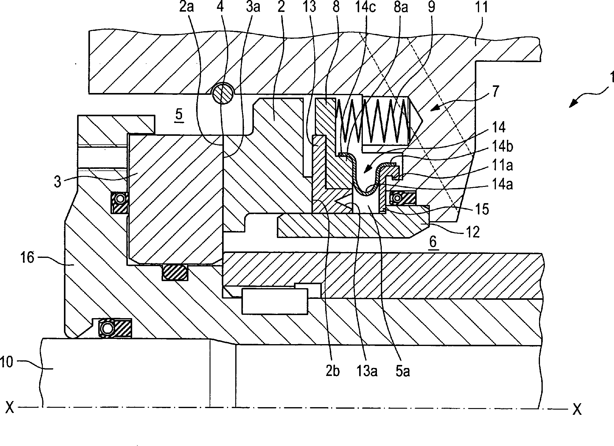
Gleitringdichtungsanordnung,
umfassend:
– einen
ersten stationären
Gleitring (2) mit einer ersten Gleitfläche (2a),
– einen
zweiten rotierenden Gleitring (3) mit einer zweiten Gleitfläche (3a),
wobei sich der rotierende Gleitring (3) gemeinsam mit einem rotierenden
Bauteil (10) dreht und wobei die Gleitflächen (2a, 3a) der Gleitringe
(2, 3) einander gegenüberliegen
und zwischen sich einen Dichtspalt (4) definieren,
– eine dynamische
Nebendichtung (13), welche an einer dem Dichtspalt (4) abgewandten
Seite (2b) des stationären Gleitrings
(2) angeordnet ist und an einem Gehäuseabdichtbereich (12) abdichtet,
– eine Vorspanneinrichtung
(7), welche eine Vorspannung in axialer Richtung auf den stationären Gleitring
(2) ausübt, und
– ein Filterelement
(14; 24), welches im Wesentlichen ringförmig ausgebildet ist und welches
in Radialrichtung weiter von einer Rotationsachse (X-X) als der
Gehäuseabdichtbereich
(12) angeordnet ist, um zu verhindern, dass sich Schmutzpartikel
an der Nebendichtung (13) oder dem Gehäuseabdichtbereich (12) ablagern.Mechanical seal assembly comprising:
A first stationary sliding ring (2) with a first sliding surface (2a),
- A second rotating seal ring (3) with a second sliding surface (3a), wherein the rotating seal ring (3) rotates together with a rotating member (10) and wherein the sliding surfaces (2a, 3a) of the slip rings (2, 3) each other opposite and define a sealing gap (4) between them,
A dynamic secondary seal (13), which is arranged on a side (2b) of the stationary sliding ring (2) facing away from the sealing gap (4) and seals on a housing sealing region (12),
- A biasing means (7) which exerts a bias in the axial direction of the stationary seal ring (2), and
- A filter element (14; 24) which is formed substantially annular and which is arranged in the radial direction further from a rotation axis (XX) than the Gehäuseabdichtbereich (12) to prevent dirt particles on the secondary seal (13) or the Store the housing sealing area (12).
Description
Die vorliegende Erfindung betrifft eine Gleitringdichtungsanordnung mit einem Filterelement, welches Schmutzablagerungen an einer dynamischen Nebendichtung der Gleitringdichtungsanordnung verhindert.The The present invention relates to a mechanical seal assembly with a filter element, which deposits dirt on a dynamic Secondary seal prevents the mechanical seal assembly.
Gleitringdichtungsanordnungen sind aus dem Stand der Technik in unterschiedlichen Ausgestaltungen bekannt. Neben hohen Temperatur- und Druckbelastungen ist ein weiteres Problem, dass häufig das Medium, welches mittels der Gleitringdichtungsanordnung abgedichtet wird, nicht vollständig rein ist, sondern Schmutzpartikel aufweist.Gleitringdichtungsanordnungen are of the prior art in different configurations known. In addition to high temperature and pressure loads is another Problem that often the medium sealed by the mechanical seal assembly will, not completely is pure, but has dirt particles.
Derartige Schmutzpartikel lagern sich besonders häufig an einer dynamischen Nebendichtung ab, welche axialen Ausgleichsbewegungen eines Gleitrings nachfolgen. Insbesondere sind dabei Ablagerungen auch auf einer Lauffläche der dynamischen Nebendichtung möglich. Derartige Schmutzablagerungen können dabei zu einem Verschleiß am hydraulischen Durchmesser, bzw. wenn eine Vorspannkraft über die dynamische Nebendichtung übertragen wird, zu einem Blockieren der Nebendichtung führen. Hierdurch kann es im schlechtesten Fall zu einem kompletten Ausfall der Gleitringdichtungsanordnung kommen.such Dirt particles accumulate particularly frequently on a dynamic secondary seal from which axial compensating movements of a sliding ring follow. In particular, deposits are also on a tread of the dynamic secondary seal possible. Such dirt deposits can doing wear to the hydraulic Diameter, or if a preload force transmitted through the dynamic secondary seal will lead to a blocking of the secondary seal. This can be done in the worst case to a complete failure of the mechanical seal assembly come.
Es ist daher Aufgabe der vorliegenden Erfindung, eine Gleitringdichtungsanordnung bereitzustellen, welche bei einfachem Aufbau und einfacher, kostengünstiger Herstellbarkeit Verschmutzungsprobleme, die zu einem Ausfall der Gleitringdichtungsanordnung führen können, vermeidet.It is therefore an object of the present invention, a mechanical seal assembly to provide which in a simple structure and easier, cheaper Producibility Pollution problems that lead to failure of the Guide mechanical seal can, avoids.
Diese Aufgabe wird durch eine Gleitringdichtungsanordnung mit den Merkmalen des Anspruchs 1 gelöst. Die Unteransprüche zeigen bevorzugte Weiterbildungen der Erfindung.These The object is achieved by a mechanical seal assembly with the features of claim 1. The dependent claims show preferred developments of the invention.
Die erfindungsgemäße Gleitringdichtungsanordnung mit den Merkmalen des Anspruchs 1 verhindert eine Ablagerung von Schmutzpartikeln, so dass eine Behinderung der Funktion der Gleitringdichtungsanordnung durch abgelagerte Schmutzpartikel vermieden werden kann. Erfindungsgemäß ist hierzu ein Filterelement vorgesehen, welches ringförmig ausgebildet ist und welches in einer Radialrichtung weiter außerhalb als ein Gehäuseabdichtbereich liegt. An diesem Gehäuseabdichtbereich dichtet eine dynamische Nebendichtung eine von einem Dichtspalt abgewandte Rückseite eines statischen Gleitrings ab. Der statische Gleitring ist dabei nicht rotierend (drehfest) ausgebildet und kann über eine Vorspanneinrichtung axial bewegt werden, um einen Dichtspalt zwischen dem stationären Gleitring und einem rotierenden Gleitring möglichst klein zu halten. Erfindungsgemäß wird insbesondere verhindert, dass sich Ablagerungen an der dynamischen Nebendichtung bilden, welche zu Undichtigkeiten der dynamischen Nebendichtung führen können und insbesondere eine Bewegung der dynamischen Nebendichtung in Axialrichtung verhindern können. Diese Bewegungsunfähigkeit in Axialrichtung, auch als „hang-up" bezeichnet, beeinträchtigt insbesondere eine Vorspannfunktion der Vorspanneinrichtung, wenn die Vorspannung über die dynamische Nebendichtung übertragen wird. Ferner wird vermieden, dass es zu einem unerwünschten Verschleiß am hydraulischen Durchmesser der dynamischen Nebendichtung aufgrund der Anlagerung von Schmutzpartikeln kommt. Die erfindungsgemäße Lösung durch das Vorsehen des ringförmigen Filterelements ermöglicht somit eine einfache und kostengünstige Verhinderung einer Ablagerung von Schmutzpartikeln an unerwünschten Stellen in der Gleitringdichtungsanordnung. Somit weist die erfindungsgemäße Gleitringdichtungsanordnung eine signifikant geringere Ausfallwahrscheinlichkeit und insbesondere auch eine erhöhte Lebensdauer auf. Somit kann die erfindungsgemäße Gleitringdichtungsanordnung auch bei verschmutzten Medien eingesetzt werden, ohne dass für die Gleitringdichtungsanordnung ein separater Sperrfluidkreislauf vorgesehen sein muss.The Inventive mechanical seal arrangement with the features of claim 1 prevents deposition of Dirt particles, so that hinders the function of the mechanical seal assembly can be avoided by deposited dirt particles. According to the invention is this a filter element is provided, which is annular and which in a radial direction farther outside than a housing sealing area lies. At this housing sealing area seals a dynamic secondary seal one of a sealing gap opposite rear side of a static slip ring. The static seal is included not rotating (rotationally fixed) and can be formed by a biasing device be moved axially to a sealing gap between the stationary seal ring and to keep a rotating slip ring as small as possible. In particular, according to the invention prevents deposits on the dynamic side seal form, which leads to leaks in the dynamic secondary seal to lead can and in particular a movement of the dynamic secondary seal in Can prevent axial direction. This immobility in the axial direction, also referred to as "hang-up", affects in particular one Preload function of the pretensioner when the bias over the transmitted dynamic secondary seal becomes. It also prevents it from becoming undesirable Wear on hydraulic diameter of the dynamic secondary seal due the accumulation of dirt particles comes. The solution according to the invention by the Provide the annular Filter element allows thus a simple and cost-effective prevention a deposition of dirt particles at undesirable locations in the mechanical seal assembly. Thus, the inventive mechanical seal assembly a significantly lower probability of default and in particular also an increased Life on. Thus, the inventive mechanical seal assembly can also be used in polluted media, without for the mechanical seal assembly a separate barrier fluid circuit must be provided.
Um vorhandene Schmutzpartikel im Medium möglichst gut herausfiltern zu können und aufnehmen zu können, weist das ringförmige Filterelement vorzugsweise eine radial nach innen gerichtete, umlaufende Vertiefung auf. Hierdurch können die Schmutzpartikel in der umlaufenden Vertiefung aufgenommen und gesammelt werden. Ferner bleibt hierbei selbst bei einer Ansammlung von einer größeren Menge von Schmutzpartikeln an den seitlichen Wandbereichen der Vertiefung immer noch genug freie Filterfläche, welche ein Durchströmen des Mediums durch das Filterelement sicherstellt. Vorzugsweise weist die Vertiefung im Schnitt eine U-förmige Gestalt auf.Around filter out existing dirt particles in the medium as well as possible can and to be able to record has the annular Filter element preferably a radially inwardly directed, circumferential Deepening up. This allows the dirt particles are absorbed in the circumferential recess and to be collected. Furthermore, this remains even with a collection from a larger amount of dirt particles on the lateral wall portions of the recess still enough free filter area, which a flow through ensures the medium through the filter element. Preferably the recess in section a U-shaped figure on.
Vorzugsweise umfasst die Vorspanneinrichtung einen Druckring, welcher eine Druckkraft über die dynamische Nebendichtung auf den stationären Gleitring überträgt. Besonders bevorzugt ist das Filterelement dabei an einer Seite an dem Druckring fixiert und an der anderen Seite an einem Gehäusebauteil fixiert.Preferably the biasing means comprises a pressure ring which provides a compressive force over the Dynamic secondary seal transmits to the stationary seal ring. Especially Preferably, the filter element is on one side on the pressure ring fixed and fixed on the other side to a housing component.
Als Filterelement wird besonders bevorzugt ein Vlies verwendet, wobei das Vlies weiter bevorzugt eine Netzdichte zwischen 0,7 μm und 1,3 μm und noch bevorzugter eine Netzdichte von ca. 1 μm aufweist.When Filter element is particularly preferably used a fleece, wherein the nonwoven further preferably has a mesh density of between 0.7 μm and 1.3 μm and still more preferably has a mesh density of about 1 micron.
Vorzugsweise ist das Filterelement aus einem einstückigen Vlies hergestellt. Alternativ kann das Filterelement auch aus wenigstens zwei ringförmigen Vlieslagen, deren Flächen in Axialrichtung ausgerichtet sind, hergesellt werden, indem die wenigstens zwei Vlieslagen an einem Umfang, vorzugsweise einem inneren Umfang, miteinander verbunden sind. Besonders bevorzugt wird das Filterelement dabei aus genau vier Vlieslagen hergestellt und weist dann eine im Schnitt im Wesentlichen M-Form auf.Preferably, the filter element is made of a one-piece nonwoven fabric. Alternatively, the filter element may also consist of at least two annular nonwoven layers whose surfaces are in the axial direction are aligned, are made by the at least two nonwoven layers on a circumference, preferably an inner circumference, are interconnected. In this case, the filter element is particularly preferably produced from exactly four nonwoven layers and then has an essentially M-shape in section.
Besonders bevorzugt ist das Filterelement druckdurchlässig ausgebildet. D. h. ein Druck vor dem Filterelement entspricht einem Druck nach dem Filterelement. Hierdurch herrscht in dem Bereich vor und nach dem Filterelement ein gleicher Druck, so dass insbesondere eine einwandfreie Funktion der Nebendichtung sichergestellt werden kann.Especially Preferably, the filter element is pressure-permeable. Ie. one Pressure in front of the filter element corresponds to a pressure downstream of the filter element. This prevails in the area before and after the filter element an equal pressure, so that in particular a perfect function the secondary seal can be ensured.
Für eine einfache und schnelle Montage wird das Filterelement vorzugsweise mittels einer Klebeverbindung an seinen beiden in Axialrichtung freien Enden fixiert.For a simple and quick assembly, the filter element is preferably by means of an adhesive bond at its two axially free ends fixed.
Die
erfindungsgemäße Gleitringdichtungsanordnung
wird besonders bevorzugt für
gasförmige Medien
verwendet und ist als gasgeschmierte Gleitringdichtungsanordnung
ausgebildet. Beispielsweise kann die erfindungsgemäße Gleitringdichtungsanordnung
bei Verdichtern für
Erdgas o. ä.
verwendet werden:
Nachfolgend werden bevorzugte Ausführungsbeispiele
der Erfindung unter Bezugnahme auf die begleitende Zeichnung im
Detail beschrieben. In der Zeichnung ist:The mechanical seal assembly according to the invention is particularly preferably used for gaseous media and is designed as a gas-lubricated mechanical seal arrangement. For example, the mechanical seal assembly according to the invention can be used in compressors for natural gas or the like:
Hereinafter, preferred embodiments of the invention will be described in detail with reference to the accompanying drawings. In the drawing is:
Nachfolgend
wird unter Bezugnahme auf die
Wie
aus
Die
Gleitringdichtungsanordnung
Ferner
umfasst die Gleitringdichtungsanordnung
Die
Vorspannfedern
Weiter
umfasst die erfindungsgemäße Gleitringdichtungsanordnung
Hierbei
herrscht in Raum
Zur
Fixierung des Ringelements
Erfindungsgemäß kann somit
verhindert werden, dass sich Schmutzpartikel insbesondere an dem
Gehäuseabdichtbereich
Da
das Filterelement
In
diesem Ausführungsbeispiel
wird das Filterelement
Nachfolgend
wird unter Bezugnahme auf
Die
Gleitringdichtungsanordnung
Claims (12)
Priority Applications (6)
| Application Number | Priority Date | Filing Date | Title |
|---|---|---|---|
| DE202008009842U DE202008009842U1 (en) | 2008-07-22 | 2008-07-22 | Mechanical seal arrangement with filter element |
| JP2011519068A JP5373080B2 (en) | 2008-07-22 | 2009-07-15 | Mechanical seal assembly having a filter member |
| EP09777213A EP2304281B1 (en) | 2008-07-22 | 2009-07-15 | Slide ring seal arrangement having filter element |
| AT09777213T ATE548596T1 (en) | 2008-07-22 | 2009-07-15 | MECHANICAL SEAL ARRANGEMENT WITH FILTER ELEMENT |
| PCT/EP2009/005150 WO2010009835A1 (en) | 2008-07-22 | 2009-07-15 | Slide ring seal arrangement having filter element |
| US12/737,471 US20110175297A1 (en) | 2008-07-22 | 2009-07-15 | Mechanical seal assembly having filter member |
Applications Claiming Priority (1)
| Application Number | Priority Date | Filing Date | Title |
|---|---|---|---|
| DE202008009842U DE202008009842U1 (en) | 2008-07-22 | 2008-07-22 | Mechanical seal arrangement with filter element |
Publications (1)
| Publication Number | Publication Date |
|---|---|
| DE202008009842U1 true DE202008009842U1 (en) | 2008-09-18 |
Family
ID=39768472
Family Applications (1)
| Application Number | Title | Priority Date | Filing Date |
|---|---|---|---|
| DE202008009842U Expired - Lifetime DE202008009842U1 (en) | 2008-07-22 | 2008-07-22 | Mechanical seal arrangement with filter element |
Country Status (6)
| Country | Link |
|---|---|
| US (1) | US20110175297A1 (en) |
| EP (1) | EP2304281B1 (en) |
| JP (1) | JP5373080B2 (en) |
| AT (1) | ATE548596T1 (en) |
| DE (1) | DE202008009842U1 (en) |
| WO (1) | WO2010009835A1 (en) |
Cited By (1)
| Publication number | Priority date | Publication date | Assignee | Title |
|---|---|---|---|---|
| CN112161063A (en) * | 2020-10-23 | 2021-01-01 | 中国舰船研究设计中心 | Submersible stern shaft tube sealing device with silt accumulation preventing function |
Families Citing this family (11)
| Publication number | Priority date | Publication date | Assignee | Title |
|---|---|---|---|---|
| DE102011111697A1 (en) * | 2011-08-24 | 2013-02-28 | Eagleburgmann Germany Gmbh & Co. Kg | Cooled mechanical seal arrangement |
| DE102011118294B3 (en) * | 2011-11-10 | 2013-04-18 | Eagleburgmann Germany Gmbh & Co. Kg | Mechanical seal assembly with Tesla pump |
| DE102013005926B4 (en) * | 2013-04-04 | 2015-12-03 | Eagleburgmann Germany Gmbh & Co. Kg | Mechanical seal assembly with different hard sliding surfaces |
| JP6509896B2 (en) | 2014-11-04 | 2019-05-08 | イーグル工業株式会社 | Mechanical seal device |
| EP3217048B1 (en) * | 2014-11-04 | 2020-09-16 | Eagle Industry Co., Ltd. | Mechanical sealing device |
| DE102015211223B3 (en) * | 2015-06-18 | 2016-07-21 | Eagleburgmann Germany Gmbh & Co. Kg | Mechanical seal with release lock |
| US10571028B2 (en) * | 2016-02-16 | 2020-02-25 | Rolls-Royce Corporation | Ceramic seal runner support system |
| CN105605226B (en) * | 2016-03-28 | 2017-08-25 | 安徽力诺环保工程有限公司 | It is a kind of can be with the sealing device of sediment prevention |
| US11193591B2 (en) * | 2017-08-03 | 2021-12-07 | Raytheon Technologies Corporation | Seal sacrificial wear indicator |
| US11054039B2 (en) | 2018-08-31 | 2021-07-06 | Rolls-Royce Corporation | Seal runner support |
| US10927960B2 (en) * | 2019-02-01 | 2021-02-23 | Rolls-Royce Corporation | Mounting assembly for a ceramic seal runner |
Family Cites Families (31)
| Publication number | Priority date | Publication date | Assignee | Title |
|---|---|---|---|---|
| US2270927A (en) * | 1940-01-18 | 1942-01-27 | American Brake Shoe & Foundry | Rotary seal |
| US2747902A (en) * | 1950-09-19 | 1956-05-29 | Crane Packing Co | Seal for wheel brake |
| US2805086A (en) * | 1952-10-30 | 1957-09-03 | Rotherm Engineering Company In | Liquid-tight and gas-tight rotating tubular joints |
| US4272084A (en) * | 1979-04-30 | 1981-06-09 | Guy F. Atkinson Company | High pressure shaft seal |
| US5368314A (en) * | 1986-10-28 | 1994-11-29 | Pacific Wietz Gmbh & Co. Kg | Contactless pressurizing-gas shaft seal |
| DE3715680A1 (en) * | 1987-05-11 | 1988-11-24 | Burgmann Dichtungswerk Feodor | MECHANICAL SEAL WITH A COOLING DEVICE |
| EP0558067B1 (en) * | 1992-02-28 | 1997-05-02 | EG&G SEALOL, INC. | Spring for centering two annular bodies relative to each other |
| US5199172A (en) * | 1992-04-02 | 1993-04-06 | John Crane Inc. | Method of manufacturing a pinless retainer for a primary ring |
| US5370403A (en) * | 1992-12-16 | 1994-12-06 | Durametallic Corporation | Non-contacting face seal |
| US5558342A (en) * | 1994-08-05 | 1996-09-24 | Durametallic Corporation | Mechanical seal with spring drive |
| DE4441474A1 (en) * | 1994-11-22 | 1996-05-23 | Kaco Gmbh Co | Liquid retaining seal for shaft with additional fibre ring dust seal |
| US5769605A (en) * | 1995-06-27 | 1998-06-23 | Kung; Cheng Ching | Sealing device for a rotary shaft |
| WO1997031206A1 (en) * | 1996-02-23 | 1997-08-28 | Tomoichiro Iwane | Mechanical seal |
| JPH09324737A (en) * | 1996-06-07 | 1997-12-16 | Hitachi Ltd | Hydraulic machine shaft seal device |
| JPH1030729A (en) * | 1996-07-15 | 1998-02-03 | Mitsubishi Heavy Ind Ltd | Mechanical seal |
| JPH10202036A (en) * | 1997-01-28 | 1998-08-04 | Matsushita Electric Ind Co Ltd | Filter for air purifier |
| US6152452A (en) * | 1997-10-17 | 2000-11-28 | Wang; Yuming | Face seal with spiral grooves |
| JP3650954B2 (en) * | 1998-09-18 | 2005-05-25 | イーグル工業株式会社 | Non-contact mechanical seal for high speed |
| US6182971B1 (en) * | 1998-12-09 | 2001-02-06 | Flowserve Management Company | Gas seal for pumps |
| EP1039184A1 (en) * | 1999-03-22 | 2000-09-27 | Dresser Rand S.A | Shaft seal |
| US6322079B1 (en) * | 1999-10-19 | 2001-11-27 | Perkinelmer, Inc. | Face seal |
| JP4180832B2 (en) * | 2002-04-24 | 2008-11-12 | イーグル工業株式会社 | Mechanical seal device |
| DE20212847U1 (en) * | 2002-08-21 | 2002-10-31 | Burgmann Dichtungswerke GmbH & Co. KG, 82515 Wolfratshausen | Split driver arrangement for a mechanical seal |
| DE20217983U1 (en) * | 2002-11-20 | 2003-02-13 | Burgmann Dichtungswerke GmbH & Co. KG, 82515 Wolfratshausen | Secondary sealing element |
| JP2004174020A (en) * | 2002-11-28 | 2004-06-24 | Mitsubishi Electric Corp | Electric vacuum cleaner |
| JP2005028219A (en) * | 2003-07-08 | 2005-02-03 | Akushii:Kk | Bag filter |
| US20050242515A1 (en) * | 2004-04-28 | 2005-11-03 | Brooks Melvin D | Dry gas seal and method for making the same |
| US7252291B2 (en) * | 2004-11-12 | 2007-08-07 | Board Of Supervisors Of Louisiana State University And Agricultural And Mechanical College | Mechanical seal having a single-piece, perforated mating ring |
| US20080237995A1 (en) * | 2007-03-30 | 2008-10-02 | Louisiana State University | Mechanical Seal with Superior Thermal Performance |
| DE202008003418U1 (en) * | 2007-11-22 | 2008-05-08 | Burgmann Industries Gmbh & Co. Kg | Double seal arrangement |
| US8006982B2 (en) * | 2008-03-28 | 2011-08-30 | Whitlow Mark S | High temperature dynamic seal |
-
2008
- 2008-07-22 DE DE202008009842U patent/DE202008009842U1/en not_active Expired - Lifetime
-
2009
- 2009-07-15 WO PCT/EP2009/005150 patent/WO2010009835A1/en not_active Ceased
- 2009-07-15 EP EP09777213A patent/EP2304281B1/en not_active Not-in-force
- 2009-07-15 US US12/737,471 patent/US20110175297A1/en not_active Abandoned
- 2009-07-15 AT AT09777213T patent/ATE548596T1/en active
- 2009-07-15 JP JP2011519068A patent/JP5373080B2/en not_active Expired - Fee Related
Cited By (1)
| Publication number | Priority date | Publication date | Assignee | Title |
|---|---|---|---|---|
| CN112161063A (en) * | 2020-10-23 | 2021-01-01 | 中国舰船研究设计中心 | Submersible stern shaft tube sealing device with silt accumulation preventing function |
Also Published As
| Publication number | Publication date |
|---|---|
| EP2304281B1 (en) | 2012-03-07 |
| EP2304281A1 (en) | 2011-04-06 |
| WO2010009835A1 (en) | 2010-01-28 |
| JP2011528779A (en) | 2011-11-24 |
| ATE548596T1 (en) | 2012-03-15 |
| JP5373080B2 (en) | 2013-12-18 |
| US20110175297A1 (en) | 2011-07-21 |
Similar Documents
| Publication | Publication Date | Title |
|---|---|---|
| EP2304281B1 (en) | Slide ring seal arrangement having filter element | |
| EP1156241B1 (en) | Annular sleeve seal, especially for mounting in housings with reduced dimensions | |
| DE3824586B4 (en) | Composite sealing | |
| EP3596363B1 (en) | Seal assembly | |
| EP3394483B1 (en) | Seal arrangement with sealing film | |
| EP3458746B1 (en) | Rotary seal assembly with pressure-activatable rotary seal, and rotary seal | |
| EP3299682B1 (en) | Seal ring and its use | |
| EP3872373B1 (en) | Seal ring and its use | |
| EP3492785B1 (en) | Sealing ring and seal arrangement comprising such a sealing ring | |
| EP0829663B1 (en) | Mechanical face seal | |
| DE102017006288A1 (en) | Radial shaft seal and its use | |
| DE102018104123B3 (en) | Seal, seal assembly and their use | |
| WO2010020364A1 (en) | Slide ring seal arrangement having an improved secondary seal | |
| EP2325530B1 (en) | Sealing ring and corresponding sealing assembly | |
| DE10334896A1 (en) | Sealing arrangement for a shaft comprises a radial shaft sealing ring with a sealing lip, and a shaft surface with a helical profiling leading the medium to be contained back into the sealed space | |
| EP4384716B1 (en) | Slotted guide ring with recirculating lubrication and piston-cylinder unit comprising same | |
| EP2466172B1 (en) | Gasket | |
| DE102012008387A1 (en) | sealing arrangement | |
| WO2015018383A1 (en) | Disengagement bearing arrangement | |
| DE102022102518B3 (en) | mechanical seal arrangement | |
| EP4001708B1 (en) | Seal ring and its use | |
| DE102014211982A1 (en) | High-pressure fuel pump for a fuel injection system | |
| DE10323319A1 (en) | Sealing unit with an axially deformable ring comprises a radially deformable spring element whose radial restoring force is at least partially transformed into an axial restoring force of the ring | |
| DE2449438C3 (en) | Inner seal arrangement for a rotary piston machine | |
| DE102024126391A1 (en) | Vibration damper for a motor vehicle |
Legal Events
| Date | Code | Title | Description |
|---|---|---|---|
| R207 | Utility model specification |
Effective date: 20081023 |
|
| R163 | Identified publications notified | ||
| R081 | Change of applicant/patentee |
Owner name: EAGLEBURGMANN GERMANY GMBH & CO. KG, DE Free format text: FORMER OWNER: BURGMANN INDUSTRIES GMBH & CO. KG, 82515 WOLFRATSHAUSEN, DE Effective date: 20100729 |
|
| R150 | Utility model maintained after payment of first maintenance fee after three years | ||
| R150 | Utility model maintained after payment of first maintenance fee after three years |
Effective date: 20111130 |
|
| R157 | Lapse of ip right after 6 years | ||
| R157 | Lapse of ip right after 6 years |
Effective date: 20150203 |