EP2014877A2 - Systems and methods for monitoring gas turbine engines - Google Patents
Systems and methods for monitoring gas turbine engines Download PDFInfo
- Publication number
- EP2014877A2 EP2014877A2 EP08252380A EP08252380A EP2014877A2 EP 2014877 A2 EP2014877 A2 EP 2014877A2 EP 08252380 A EP08252380 A EP 08252380A EP 08252380 A EP08252380 A EP 08252380A EP 2014877 A2 EP2014877 A2 EP 2014877A2
- Authority
- EP
- European Patent Office
- Prior art keywords
- debris
- oil
- monitoring
- gas turbine
- engine
- Prior art date
- Legal status (The legal status is an assumption and is not a legal conclusion. Google has not performed a legal analysis and makes no representation as to the accuracy of the status listed.)
- Granted
Links
Images
Classifications
-
- F—MECHANICAL ENGINEERING; LIGHTING; HEATING; WEAPONS; BLASTING
- F01—MACHINES OR ENGINES IN GENERAL; ENGINE PLANTS IN GENERAL; STEAM ENGINES
- F01D—NON-POSITIVE DISPLACEMENT MACHINES OR ENGINES, e.g. STEAM TURBINES
- F01D21/00—Shutting-down of machines or engines, e.g. in emergency; Regulating, controlling, or safety means not otherwise provided for
- F01D21/10—Shutting-down of machines or engines, e.g. in emergency; Regulating, controlling, or safety means not otherwise provided for responsive to unwanted deposits on blades, in working-fluid conduits or the like
-
- F—MECHANICAL ENGINEERING; LIGHTING; HEATING; WEAPONS; BLASTING
- F01—MACHINES OR ENGINES IN GENERAL; ENGINE PLANTS IN GENERAL; STEAM ENGINES
- F01D—NON-POSITIVE DISPLACEMENT MACHINES OR ENGINES, e.g. STEAM TURBINES
- F01D25/00—Component parts, details, or accessories, not provided for in, or of interest apart from, other groups
- F01D25/18—Lubricating arrangements
-
- F—MECHANICAL ENGINEERING; LIGHTING; HEATING; WEAPONS; BLASTING
- F02—COMBUSTION ENGINES; HOT-GAS OR COMBUSTION-PRODUCT ENGINE PLANTS
- F02C—GAS-TURBINE PLANTS; AIR INTAKES FOR JET-PROPULSION PLANTS; CONTROLLING FUEL SUPPLY IN AIR-BREATHING JET-PROPULSION PLANTS
- F02C7/00—Features, components parts, details or accessories, not provided for in, or of interest apart form groups F02C1/00 - F02C6/00; Air intakes for jet-propulsion plants
- F02C7/06—Arrangements of bearings; Lubricating
-
- G—PHYSICS
- G01—MEASURING; TESTING
- G01N—INVESTIGATING OR ANALYSING MATERIALS BY DETERMINING THEIR CHEMICAL OR PHYSICAL PROPERTIES
- G01N15/00—Investigating characteristics of particles; Investigating permeability, pore-volume or surface-area of porous materials
- G01N15/06—Investigating concentration of particle suspensions
- G01N15/0656—Investigating concentration of particle suspensions using electric, e.g. electrostatic methods or magnetic methods
-
- G—PHYSICS
- G01—MEASURING; TESTING
- G01N—INVESTIGATING OR ANALYSING MATERIALS BY DETERMINING THEIR CHEMICAL OR PHYSICAL PROPERTIES
- G01N33/00—Investigating or analysing materials by specific methods not covered by groups G01N1/00 - G01N31/00
- G01N33/26—Oils; Viscous liquids; Paints; Inks
- G01N33/28—Oils, i.e. hydrocarbon liquids
- G01N33/2835—Specific substances contained in the oils or fuels
- G01N33/2858—Metal particles
-
- G—PHYSICS
- G01—MEASURING; TESTING
- G01N—INVESTIGATING OR ANALYSING MATERIALS BY DETERMINING THEIR CHEMICAL OR PHYSICAL PROPERTIES
- G01N33/00—Investigating or analysing materials by specific methods not covered by groups G01N1/00 - G01N31/00
- G01N33/26—Oils; Viscous liquids; Paints; Inks
- G01N33/28—Oils, i.e. hydrocarbon liquids
- G01N33/2888—Lubricating oil characteristics, e.g. deterioration
-
- F—MECHANICAL ENGINEERING; LIGHTING; HEATING; WEAPONS; BLASTING
- F05—INDEXING SCHEMES RELATING TO ENGINES OR PUMPS IN VARIOUS SUBCLASSES OF CLASSES F01-F04
- F05D—INDEXING SCHEME FOR ASPECTS RELATING TO NON-POSITIVE-DISPLACEMENT MACHINES OR ENGINES, GAS-TURBINES OR JET-PROPULSION PLANTS
- F05D2260/00—Function
- F05D2260/80—Diagnostics
-
- F—MECHANICAL ENGINEERING; LIGHTING; HEATING; WEAPONS; BLASTING
- F05—INDEXING SCHEMES RELATING TO ENGINES OR PUMPS IN VARIOUS SUBCLASSES OF CLASSES F01-F04
- F05D—INDEXING SCHEME FOR ASPECTS RELATING TO NON-POSITIVE-DISPLACEMENT MACHINES OR ENGINES, GAS-TURBINES OR JET-PROPULSION PLANTS
- F05D2270/00—Control
- F05D2270/01—Purpose of the control system
- F05D2270/11—Purpose of the control system to prolong engine life
Definitions
- the disclosure generally relates to gas turbine engine monitoring.
- Monitoring of lubrication oil of gas turbine engines for debris can be accomplished using a variety of techniques.
- chemical analysis can be used to identify particles of deteriorating mechanical components.
- chemical analysis can be quite time-consuming and typically requires equipment that is used by ground maintenance personnel.
- Another technique involves the use of an oil filter that is removed from the engine so that captured debris can be analyzed. This technique also is typically performed by ground maintenance personnel.
- Another technique involves debris capture devices, such as magnetic chip detectors.
- magnetic chip detectors tend to be relatively inefficient at detecting debris.
- a representative embodiment of a method comprises: monitoring lubrication oil at multiple locations of the gas turbine engine to detect a presence of debris in the oil; determining a characteristic of the debris in the oil; and correlating the characteristic of the debris with the location of detection to determine whether the engine is operating within predetermined limits while the gas turbine engine is operating.
- Another embodiment of a method comprises: monitoring lubrication oil, at multiple locations of the gas turbine engine, to detect a presence of debris in the oil; approximating a source of origin of the debris; determining a characteristic of the debris; and correlating the characteristic with the source to determine whether the engine is operating within predetermined limits; the monitoring, approximating, determining and correlating being performed while the gas turbine engine is operating.
- a representative embodiment of a system comprises: multiple debris capture devices operative to monitor lubrication oil of a gas turbine engine to detect a presence of debris in the oil; an oil debris monitor operative to monitor lubrication oil to determine a characteristic of the debris; and an oil analysis system operative to receive information corresponding to the presence of debris in the oil from the debris capture devices and information corresponding to the characteristic of the debris from the oil debris monitor; the oil analysis system being further operative to approximate a source of origin of the debris based on the information provided by the debris capture devices and correlate the characteristic with the source to determine whether the engine is operating within predetermined limits.
- an oil analysis system receives information from various devices, such as one or more debris capture devices and one or more oil debris monitors.
- some embodiments can incorporate only one oil debris monitor that is configured to detect the presence of magnetic and nonmagnetic particles in the lubrication oil system of a gas turbine engine.
- the debris capture devices e.g., magnetic chip detectors, can be located at various locations of the lubrication oil system, thereby assisting in localizing the source of any debris. Information from the debris capture devices and oil debris monitor is analyzed to determine whether or not the engine is operating within predetermined limits.
- a notification can be provided to the cockpit of an aircraft to which the gas turbine engine is mounted. Additionally or alternatively, notification can be sent to a ground site, such as to ground maintenance personnel via wireless communication, for example.
- system 100 includes a gas turbine engine 101 that incorporates a fan 102, a compressor section 104, a combustion section 106 and a turbine section 108.
- gas turbine engine 101 is configured as a turbofan, there is no intention to limit the invention to use with turbofans as use with other types of gas turbine engines is contemplated.
- System 100 also incorporates an oil analysis system 120 that communicates with at least one oil debris monitor (ODM) and at least one debris capture device (DCD) that monitor a lubrication oil system (not shown) of the engine.
- ODM oil debris monitor
- DCD debris capture device
- one ODM (122) and two DCDs (124, 126) are depicted, although various other numbers could be used in other embodiments.
- the DCDs and ODM are associated with an accessory gearbox 128, with DCD 124 being located at position A, DCD 126 being located at position B, and ODM 122 being located at position C.
- DCD 124 incorporates a filter 132 that enables the detection of both magnetic and nonmagnetic particles carried by lubrication oil of the engine.
- DCD 126 is configured as a magnetic chip detector and, thus, is only capable of detecting magnetic particles.
- each of the DCDs is associated with and is located downstream in the lubrication oil system of a component of the gas turbine engine that is subject to wear. Therefore, detection of debris by one of the DCDs can indicate that the associated component is degrading.
- information regarding the presence of debris is provided to the oil analysis system 120 by the DCDs.
- information corresponding to one or more characteristics of the debris is provided to the oil analysis system by ODM 122. It should be noted that, in some embodiments, the ODM can merely provided information regarding the presence of debris.
- ODM 122 incorporates an inductor coil 134 that enables the ODM to determine one or more of debris particle size, debris particle count, debris particle mass, and debris particle composition (e.g., ferrous/non-ferrous). Each of these characteristics can be analyzed at a single point in time, cumulatively over time and/or as a rate change over time, for example.
- the oil analysis system 120 correlates the information provided by the DCDs and ODM. This correlation can be used to determine: an identity of one or more components that are responsible for the debris; the extent of degradation of the one or more components; and/or whether or not the engine is operating within predetermined limits.
- the oil analysis system can store data related to performance parameters of various components across a life cycle of the components. Thus, if debris is sensed and a determination is made that a particular component is the likely source of origin of the debris, one or more of the determined characteristics of the debris can be correlated with the stored performance parameters of that component. Such a correlation can be used to determine expected performance of that component. By way of example, a determination could be made that the component is operating properly, that the component requires maintenance at the next regular maintenance cycle, or that the component is approaching failure.
- a notification can be sent.
- a notification is sent to the cockpit informing the aircrew of the detected condition.
- information can be provided to ground personnel, such as via a wired or wireless interface.
- wireless transmission some embodiments could transmit information corresponding to the detected condition prior to engine shutdown, such as during flight.
- FIG. 2 is a flowchart depicting functionality of an embodiment of a system for monitoring a gas turbine engine.
- the functionality may be construed as beginning a block 202, in which lubrication oil is monitored at multiple locations of a gas turbine to detect a presence of debris in the oil.
- a characteristic of the debris in the oil is determined.
- the characteristic of the debris is correlated with the location of detection to determine whether the engine is operating within predetermined limits while the gas turbine engine is operating.
- FIG. 3 is a flowchart depicting functionality of another embodiment of a system for monitoring a gas turbine engine.
- the functionality may be construed as beginning at block 302, in which lubrication oil is monitored to detect the presence of debris in the oil.
- the lubrication oil can be monitored at multiple locations, such as by using a separate DCD at each such location.
- a source of origin of the debris is approximated.
- a first of the DCDs to detect debris can be assumed to be the closest DCD downstream of the component that is providing the debris to the lubrication oil flow. As such, once such a DCD has been identified, components upstream of that DCD can be considered suspect.
- various other techniques could be used in such a determination, such as those that reference secondary indications, e.g., vibration and/or temperature indications.
- a characteristic of the debris is determined.
- various characteristics such as particle size, particle count and particle mass, can be determined by an ODM.
- various components have known degradation schedules over their life cycles that can, within a reasonable degree of certainty, be used to ascertain the remaining performance potential of a component based on the characteristics of debris detected.
- the characteristic of the debris is correlated with the source of the debris to determine whether the engine is operating within predetermined limits.
- an embodiment of an oil analysis system may determine that the engine is not operating within predetermined limits. Responsive to such a determination, and depending on the degree by which the threshold value is exceeded, an alert notification may be provided. Notably, such an alert can include informing the flight crew of the detected condition and/or notifying ground maintenance personnel.
- system 400 includes a lubrication oil system 402 and an oil analysis system 403.
- the lubrication oil system generally includes an oil reservoir 404 that provides lubrication oil to conduit 406 via a main oil pump 408. From the main oil pump, the oil passes through an oil debris monitor 410 and then through a main oil filter 412 before being directed through oil cooler 414. Downstream of the oil cooler, the lubrication oil is provided to various components such as a gear box 414, as well as components associated with a front bearing compartment 416, a mid bearing compartment 418, and a rear bearing compartment 420.
- scavenge pump 422 provides oil to a DCD 424
- scavenge pump 426 provides oil to DCD 428
- scavenge pump 430 provides oil to DCD 432
- scavenge pump 434 provides oil to DCD 436.
- oil is provided to a de-aerator 440 that separates air from the oil.
- air is provided to a de-oiler 442 and then overboard via a breather pressure valve 444 and overboard vent 446. Air also is provided to the de-oiler from the gearbox and the bearing compartments, as well as from the oil reservoir in this embodiment. From the deaerator, oil is provided back to the oil reservoir.
- the lubrication oil system incorporates various sensors for monitoring temperature, e.g., sensor 452, and pressure, e.g., sensor 454, at multiple locations throughout the system. Although, in some embodiments, these sensors are used as inputs for operating various components, such as oil pumps and/or coolers, these sensors can be used for providing inputs to the oil analysis system for evaluating operating parameters for the gas turbine engine.
- the oil analysis system 403 can receive inputs from one or more of the DCDs as well as from the ODM.
- the DCDs can provide information corresponding to whether debris has been sensed in the lubrication oil. This information can be provided upon detection and/or responsive to a request for information from the oil analysis system and/or ODM 410.
- the ODM can provide information regarding debris to the oil analysis system in one or more of various manners. That is, the ODM can provide information corresponding to the presence of debris and/or characteristics of the debris, such as particle size, particle mass and/or particle count.
- DCD 432 provides information to the oil analysis system indicating that debris is present in the lubrication oil
- some embodiments of the oil analysis system may determine that a thrust bearing lubricated by oil of the mid bearing compartment 418 is the source of the debris. This could clearly be the case in those embodiments in which the mid-bearing compartment provides lubrication oil to only the thrust bearing and none of the other DCDs have detected debris in their respective oil flows.
- the oil analysis system could respond to such an indication by monitoring information provided by the ODM.
- the ODM could be configured to provide information regarding particle size of the debris initially sensed by the DCD.
- the oil analysis system can correlate the received information with information corresponding to thrust bearing trends in order to predict future operating parameters of the thrust bearing. If it is determined that the thrust bearing is operating within the pre-determined limits established for normal operation, a notification may or may not be sent to the flight crew. If, however, the information indicates that continued operation of the engine could result in failure of the thrust bearing and/or performance that is degraded beyond the pre-determined operating limits, notification could be sent to the flight crew so that appropriate corrective action can be taken. Regardless of whether the flight crew is notified, information corresponding to the detected debris can be stored and/or provided for later analysis, such as by ground personnel.
- Various functionality can be implemented in hardware and/or software.
- a computing device can be used to implement various functionality, such as that depicted in FIGs. 2 and 3 .
- such a computing device can include a processor, memory, and one or more input and/or output (I/O) device interface(s) that are communicatively coupled via a local interface.
- the local interface can include, for example but not limited to, one or more buses and/or other wired or wireless connections.
- the local interface may have additional elements, which are omitted for simplicity, such as controllers, buffers (caches), drivers, repeaters, and receivers to enable communications. Further, the local interface may include address, control, and/or data connections to enable appropriate communications among the aforementioned components.
- the processor may be a hardware device for executing software, particularly software stored in memory.
- the processor can be a custom made or commercially available processor, a central processing unit (CPU), an auxiliary processor among several processors associated with the computing device, a semiconductor based microprocessor (in the form of a microchip or chip set), a macroprocessor, or generally any device for executing software instructions.
- the memory can include any one or combination of volatile memory elements (e.g., random access memory (RAM, such as DRAM, SRAM, SDRAM, VRAM, etc. )) and/or nonvolatile memory elements (e.g., ROM, hard drive, tape, CD-ROM, etc.).
- volatile memory elements e.g., random access memory (RAM, such as DRAM, SRAM, SDRAM, VRAM, etc.
- nonvolatile memory elements e.g., ROM, hard drive, tape, CD-ROM, etc.
- the memory may incorporate electronic, magnetic, optical, and/or other types of storage media.
- the memory can also have a distributed architecture, where various components are situated remotely from one another, but can be accessed by the processor.
- the software in the memory may include one or more separate programs, each of which includes an ordered listing of executable instructions for implementing logical functions.
- a system component embodied as software may also be construed as a source program, executable program (object code), script, or any other entity comprising a set of instructions to be performed.
- the program is translated via a compiler, assembler, interpreter, or the like, which may or may not be included within the memory.
- the Input/Output devices that may be coupled to system I/O Interface(s) may include input devices, for example but not limited to, a keyboard, mouse, scanner, microphone, camera, proximity device, etc. Further, the Input/Output devices may also include output devices, for example but not limited to, a printer, display, etc. Finally, the Input/Output devices may further include devices that communicate both as inputs and outputs, for instance but not limited to, a modulator/demodulator (modem; for accessing another device, system, or network), a radio frequency (RF) or other transceiver, a telephonic interface, a bridge, a router, etc.
- modem for accessing another device, system, or network
- RF radio frequency
- the processor can be configured to execute software stored within the memory, to communicate data to and from the memory, and to generally control operations of the computing device pursuant to the software.
- Software in memory, in whole or in part, is read by the processor, perhaps buffered within the processor, and then executed.
- each block can be interpreted to represent a module, segment, or portion of code, which comprises one or more executable instructions for implementing the specified logical function(s).
- the functions noted in the blocks may occur out of the order and/or not at all. For example, two blocks shown in succession may in fact be executed substantially concurrently or the blocks may sometimes be executed in the reverse order, depending upon the functionality involved.
- any of the functionality described herein can be embodied in any computer-readable medium for use by or in connection with an instruction execution system, apparatus, or device, such as a computer-based system, processor-containing system, or other system that can fetch the instructions from the instruction execution system, apparatus, or device and execute the instructions.
- a "computer-readable medium” contains, stores, communicates, propagates and/or transports the program for use by or in connection with the instruction execution system, apparatus, or device.
- the computer readable medium can be, for example but not limited to, an electronic, magnetic, optical, electromagnetic, infrared, or semiconductor system, apparatus, or device.
- a computer-readable medium includes a portable computer diskette (magnetic), a random access memory (RAM) (electronic), a read-only memory (ROM) (electronic), an erasable programmable read-only memory (EPROM or Flash memory) (electronic), and a portable compact disc read-only memory (CDROM) (optical).
- RAM random access memory
- ROM read-only memory
- EPROM or Flash memory erasable programmable read-only memory
- CDROM compact disc read-only memory
Landscapes
- Engineering & Computer Science (AREA)
- Chemical & Material Sciences (AREA)
- Health & Medical Sciences (AREA)
- Life Sciences & Earth Sciences (AREA)
- Analytical Chemistry (AREA)
- General Physics & Mathematics (AREA)
- General Engineering & Computer Science (AREA)
- Mechanical Engineering (AREA)
- Pathology (AREA)
- Physics & Mathematics (AREA)
- Immunology (AREA)
- Biochemistry (AREA)
- General Health & Medical Sciences (AREA)
- Oil, Petroleum & Natural Gas (AREA)
- Chemical Kinetics & Catalysis (AREA)
- Medicinal Chemistry (AREA)
- Combustion & Propulsion (AREA)
- Food Science & Technology (AREA)
- General Chemical & Material Sciences (AREA)
- Dispersion Chemistry (AREA)
- Testing Of Devices, Machine Parts, Or Other Structures Thereof (AREA)
- Heterocyclic Carbon Compounds Containing A Hetero Ring Having Nitrogen And Oxygen As The Only Ring Hetero Atoms (AREA)
Abstract
Description
- The U.S. Government may have an interest in the subject matter of this disclosure as provided for by the terms of contract number F33615-03-D-23540014 awarded by the United States Air Force.
- The disclosure generally relates to gas turbine engine monitoring.
- Monitoring of lubrication oil of gas turbine engines for debris can be accomplished using a variety of techniques. By way of example, chemical analysis can be used to identify particles of deteriorating mechanical components. However, chemical analysis can be quite time-consuming and typically requires equipment that is used by ground maintenance personnel. Another technique involves the use of an oil filter that is removed from the engine so that captured debris can be analyzed. This technique also is typically performed by ground maintenance personnel.
- Another technique involves debris capture devices, such as magnetic chip detectors. Unfortunately, magnetic chip detectors tend to be relatively inefficient at detecting debris.
- Systems and methods for monitoring gas turbine engines are provided. In this regard, a representative embodiment of a method comprises: monitoring lubrication oil at multiple locations of the gas turbine engine to detect a presence of debris in the oil; determining a characteristic of the debris in the oil; and correlating the characteristic of the debris with the location of detection to determine whether the engine is operating within predetermined limits while the gas turbine engine is operating.
- Another embodiment of a method comprises: monitoring lubrication oil, at multiple locations of the gas turbine engine, to detect a presence of debris in the oil; approximating a source of origin of the debris; determining a characteristic of the debris; and correlating the characteristic with the source to determine whether the engine is operating within predetermined limits; the monitoring, approximating, determining and correlating being performed while the gas turbine engine is operating.
- A representative embodiment of a system comprises: multiple debris capture devices operative to monitor lubrication oil of a gas turbine engine to detect a presence of debris in the oil; an oil debris monitor operative to monitor lubrication oil to determine a characteristic of the debris; and an oil analysis system operative to receive information corresponding to the presence of debris in the oil from the debris capture devices and information corresponding to the characteristic of the debris from the oil debris monitor; the oil analysis system being further operative to approximate a source of origin of the debris based on the information provided by the debris capture devices and correlate the characteristic with the source to determine whether the engine is operating within predetermined limits.
- Other systems, methods, features and/or advantages of this disclosure will be or may become apparent to one with skill in the art upon examination of the following drawings and detailed description. It is intended that all such additional systems, methods, features and/or advantages be included within this description and be within the scope of the present disclosure.
- Many aspects of the disclosure can be better understood with reference to the following drawings. The components in the drawings are not necessarily to scale. Moreover, in the drawings, like reference numerals designate corresponding parts throughout the several views.
-
FIG. 1 is a schematic diagram of an embodiment of a system for monitoring a gas turbine engine. -
FIG. 2 is a flowchart depicting functionality of an embodiment of a system for monitoring a gas turbine engine. -
FIG. 3 is a flowchart depicting functionality of another embodiment of a system for monitoring a gas turbine engine. -
FIG. 4 is a schematic diagram of another embodiment of a system for monitoring a gas turbine engine. - Systems and methods for monitoring gas turbine engines are provided. In this regard, several exemplary embodiments will be described. In some embodiments, an oil analysis system receives information from various devices, such as one or more debris capture devices and one or more oil debris monitors. Notably, some embodiments can incorporate only one oil debris monitor that is configured to detect the presence of magnetic and nonmagnetic particles in the lubrication oil system of a gas turbine engine. Additionally, the debris capture devices, e.g., magnetic chip detectors, can be located at various locations of the lubrication oil system, thereby assisting in localizing the source of any debris. Information from the debris capture devices and oil debris monitor is analyzed to determine whether or not the engine is operating within predetermined limits. In some embodiments, depending upon the severity of a sensed out-of-limit condition, a notification can be provided to the cockpit of an aircraft to which the gas turbine engine is mounted. Additionally or alternatively, notification can be sent to a ground site, such as to ground maintenance personnel via wireless communication, for example.
- Reference now made to
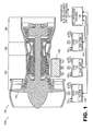
FIG. 1 , which schematically depicts an embodiment of a system for monitoring a gas turbine engine. As shown inFIG. 1 ,system 100 includes agas turbine engine 101 that incorporates afan 102, acompressor section 104, acombustion section 106 and aturbine section 108. Althoughengine 101 is configured as a turbofan, there is no intention to limit the invention to use with turbofans as use with other types of gas turbine engines is contemplated. -
System 100 also incorporates anoil analysis system 120 that communicates with at least one oil debris monitor (ODM) and at least one debris capture device (DCD) that monitor a lubrication oil system (not shown) of the engine. In this embodiment, one ODM (122) and two DCDs (124, 126) are depicted, although various other numbers could be used in other embodiments. Notably, the DCDs and ODM are associated with anaccessory gearbox 128, with DCD 124 being located at position A,DCD 126 being located at position B, andODM 122 being located at position C. - In
FIG. 1 , DCD 124 incorporates afilter 132 that enables the detection of both magnetic and nonmagnetic particles carried by lubrication oil of the engine. In contrast,DCD 126 is configured as a magnetic chip detector and, thus, is only capable of detecting magnetic particles. Typically, each of the DCDs is associated with and is located downstream in the lubrication oil system of a component of the gas turbine engine that is subject to wear. Therefore, detection of debris by one of the DCDs can indicate that the associated component is degrading. - In the embodiment of
FIG. 1 , information regarding the presence of debris is provided to theoil analysis system 120 by the DCDs. In contrast, information corresponding to one or more characteristics of the debris is provided to the oil analysis system byODM 122. It should be noted that, in some embodiments, the ODM can merely provided information regarding the presence of debris. - In the embodiment of
FIG. 1 , ODM 122 incorporates aninductor coil 134 that enables the ODM to determine one or more of debris particle size, debris particle count, debris particle mass, and debris particle composition (e.g., ferrous/non-ferrous). Each of these characteristics can be analyzed at a single point in time, cumulatively over time and/or as a rate change over time, for example. - The
oil analysis system 120 correlates the information provided by the DCDs and ODM. This correlation can be used to determine: an identity of one or more components that are responsible for the debris; the extent of degradation of the one or more components; and/or whether or not the engine is operating within predetermined limits. In this regard, the oil analysis system can store data related to performance parameters of various components across a life cycle of the components. Thus, if debris is sensed and a determination is made that a particular component is the likely source of origin of the debris, one or more of the determined characteristics of the debris can be correlated with the stored performance parameters of that component. Such a correlation can be used to determine expected performance of that component. By way of example, a determination could be made that the component is operating properly, that the component requires maintenance at the next regular maintenance cycle, or that the component is approaching failure. - Regardless of the particular determination, a notification can be sent. In this regard, in some embodiments, a notification is sent to the cockpit informing the aircrew of the detected condition. Additionally or alternatively, information can be provided to ground personnel, such as via a wired or wireless interface. In the case of wireless transmission, some embodiments could transmit information corresponding to the detected condition prior to engine shutdown, such as during flight.
-
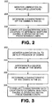
FIG. 2 is a flowchart depicting functionality of an embodiment of a system for monitoring a gas turbine engine. In this regard, the functionality (or method) may be construed as beginning ablock 202, in which lubrication oil is monitored at multiple locations of a gas turbine to detect a presence of debris in the oil. Inblock 204, a characteristic of the debris in the oil is determined. Thereafter, such as depicted inblock 206, the characteristic of the debris is correlated with the location of detection to determine whether the engine is operating within predetermined limits while the gas turbine engine is operating. -
FIG. 3 is a flowchart depicting functionality of another embodiment of a system for monitoring a gas turbine engine. As shown inFIG. 3 , the functionality (or method) may be construed as beginning atblock 302, in which lubrication oil is monitored to detect the presence of debris in the oil. In this regard, the lubrication oil can be monitored at multiple locations, such as by using a separate DCD at each such location. Inblock 304, a source of origin of the debris is approximated. By way of example, a first of the DCDs to detect debris can be assumed to be the closest DCD downstream of the component that is providing the debris to the lubrication oil flow. As such, once such a DCD has been identified, components upstream of that DCD can be considered suspect. Clearly, various other techniques could be used in such a determination, such as those that reference secondary indications, e.g., vibration and/or temperature indications. - In
block 306, a characteristic of the debris is determined. By way of example, one or more of various characteristics, such as particle size, particle count and particle mass, can be determined by an ODM. Notably, various components have known degradation schedules over their life cycles that can, within a reasonable degree of certainty, be used to ascertain the remaining performance potential of a component based on the characteristics of debris detected. - In
block 308, the characteristic of the debris is correlated with the source of the debris to determine whether the engine is operating within predetermined limits. By way of example, if the particle size of the debris exceeds a threshold particle size for a particular component, an embodiment of an oil analysis system may determine that the engine is not operating within predetermined limits. Responsive to such a determination, and depending on the degree by which the threshold value is exceeded, an alert notification may be provided. Notably, such an alert can include informing the flight crew of the detected condition and/or notifying ground maintenance personnel. - Another embodiment of a system for monitoring a gas turbine engine is depicted schematically in
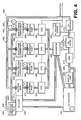
FIG. 4 . As shown inFIG. 4 ,system 400 includes alubrication oil system 402 and anoil analysis system 403. The lubrication oil system generally includes anoil reservoir 404 that provides lubrication oil toconduit 406 via amain oil pump 408. From the main oil pump, the oil passes through anoil debris monitor 410 and then through amain oil filter 412 before being directed throughoil cooler 414. Downstream of the oil cooler, the lubrication oil is provided to various components such as agear box 414, as well as components associated with afront bearing compartment 416, amid bearing compartment 418, and arear bearing compartment 420. - Downstream of the gear box and bearing compartments are located scavenge pumps, each of which provides oil to a DCD. Specifically, scavenge
pump 422 provides oil to aDCD 424, scavenge pump 426 provides oil toDCD 428, scavenge pump 430 provides oil toDCD 432, and scavengepump 434 provides oil toDCD 436. From the DCDs, oil is provided to a de-aerator 440 that separates air from the oil. From the de-aerator, air is provided to a de-oiler 442 and then overboard via abreather pressure valve 444 and overboard vent 446. Air also is provided to the de-oiler from the gearbox and the bearing compartments, as well as from the oil reservoir in this embodiment. From the deaerator, oil is provided back to the oil reservoir. - It should also be noted that the lubrication oil system incorporates various sensors for monitoring temperature, e.g.,
sensor 452, and pressure, e.g.,sensor 454, at multiple locations throughout the system. Although, in some embodiments, these sensors are used as inputs for operating various components, such as oil pumps and/or coolers, these sensors can be used for providing inputs to the oil analysis system for evaluating operating parameters for the gas turbine engine. - In this regard, the
oil analysis system 403 can receive inputs from one or more of the DCDs as well as from the ODM. In particular, the DCDs can provide information corresponding to whether debris has been sensed in the lubrication oil. This information can be provided upon detection and/or responsive to a request for information from the oil analysis system and/orODM 410. Notably, the ODM can provide information regarding debris to the oil analysis system in one or more of various manners. That is, the ODM can provide information corresponding to the presence of debris and/or characteristics of the debris, such as particle size, particle mass and/or particle count. - By way of example, if
DCD 432 provides information to the oil analysis system indicating that debris is present in the lubrication oil, some embodiments of the oil analysis system may determine that a thrust bearing lubricated by oil of themid bearing compartment 418 is the source of the debris. This could clearly be the case in those embodiments in which the mid-bearing compartment provides lubrication oil to only the thrust bearing and none of the other DCDs have detected debris in their respective oil flows. The oil analysis system could respond to such an indication by monitoring information provided by the ODM. In this regard, the ODM could be configured to provide information regarding particle size of the debris initially sensed by the DCD. Responsive to such information from the ODM, the oil analysis system can correlate the received information with information corresponding to thrust bearing trends in order to predict future operating parameters of the thrust bearing. If it is determined that the thrust bearing is operating within the pre-determined limits established for normal operation, a notification may or may not be sent to the flight crew. If, however, the information indicates that continued operation of the engine could result in failure of the thrust bearing and/or performance that is degraded beyond the pre-determined operating limits, notification could be sent to the flight crew so that appropriate corrective action can be taken. Regardless of whether the flight crew is notified, information corresponding to the detected debris can be stored and/or provided for later analysis, such as by ground personnel. - Various functionality, such as that described above in the flowcharts with respect to an oil analysis system, can be implemented in hardware and/or software. In this regard, a computing device can be used to implement various functionality, such as that depicted in
FIGs. 2 and 3 . - In terms of hardware architecture, such a computing device can include a processor, memory, and one or more input and/or output (I/O) device interface(s) that are communicatively coupled via a local interface. The local interface can include, for example but not limited to, one or more buses and/or other wired or wireless connections. The local interface may have additional elements, which are omitted for simplicity, such as controllers, buffers (caches), drivers, repeaters, and receivers to enable communications. Further, the local interface may include address, control, and/or data connections to enable appropriate communications among the aforementioned components.
- The processor may be a hardware device for executing software, particularly software stored in memory. The processor can be a custom made or commercially available processor, a central processing unit (CPU), an auxiliary processor among several processors associated with the computing device, a semiconductor based microprocessor (in the form of a microchip or chip set), a macroprocessor, or generally any device for executing software instructions.
- The memory can include any one or combination of volatile memory elements (e.g., random access memory (RAM, such as DRAM, SRAM, SDRAM, VRAM, etc.)) and/or nonvolatile memory elements (e.g., ROM, hard drive, tape, CD-ROM, etc.). Moreover, the memory may incorporate electronic, magnetic, optical, and/or other types of storage media. Note that the memory can also have a distributed architecture, where various components are situated remotely from one another, but can be accessed by the processor.
- The software in the memory may include one or more separate programs, each of which includes an ordered listing of executable instructions for implementing logical functions. A system component embodied as software may also be construed as a source program, executable program (object code), script, or any other entity comprising a set of instructions to be performed. When constructed as a source program, the program is translated via a compiler, assembler, interpreter, or the like, which may or may not be included within the memory.
- The Input/Output devices that may be coupled to system I/O Interface(s) may include input devices, for example but not limited to, a keyboard, mouse, scanner, microphone, camera, proximity device, etc. Further, the Input/Output devices may also include output devices, for example but not limited to, a printer, display, etc. Finally, the Input/Output devices may further include devices that communicate both as inputs and outputs, for instance but not limited to, a modulator/demodulator (modem; for accessing another device, system, or network), a radio frequency (RF) or other transceiver, a telephonic interface, a bridge, a router, etc.
- When the computing device is in operation, the processor can be configured to execute software stored within the memory, to communicate data to and from the memory, and to generally control operations of the computing device pursuant to the software. Software in memory, in whole or in part, is read by the processor, perhaps buffered within the processor, and then executed.
- One should note that the flowcharts included herein show the architecture, functionality, and operation of a possible implementation of software. In this regard, each block can be interpreted to represent a module, segment, or portion of code, which comprises one or more executable instructions for implementing the specified logical function(s). It should also be noted that in some alternative implementations, the functions noted in the blocks may occur out of the order and/or not at all. For example, two blocks shown in succession may in fact be executed substantially concurrently or the blocks may sometimes be executed in the reverse order, depending upon the functionality involved.
- One should note that any of the functionality described herein can be embodied in any computer-readable medium for use by or in connection with an instruction execution system, apparatus, or device, such as a computer-based system, processor-containing system, or other system that can fetch the instructions from the instruction execution system, apparatus, or device and execute the instructions. In the context of this document, a "computer-readable medium" contains, stores, communicates, propagates and/or transports the program for use by or in connection with the instruction execution system, apparatus, or device. The computer readable medium can be, for example but not limited to, an electronic, magnetic, optical, electromagnetic, infrared, or semiconductor system, apparatus, or device. More specific examples (a nonexhaustive list) of a computer-readable medium include a portable computer diskette (magnetic), a random access memory (RAM) (electronic), a read-only memory (ROM) (electronic), an erasable programmable read-only memory (EPROM or Flash memory) (electronic), and a portable compact disc read-only memory (CDROM) (optical).
- It should be emphasized that the above-described embodiments are merely possible examples of implementations set forth for a clear understanding of the principles of this disclosure. Many variations and modifications may be made to the above-described embodiments without departing substantially from the principles of the disclosure. All such modifications and variations are intended to be included herein within the scope of this disclosure and protected by the accompanying claims.
Claims (15)
- A method for monitoring a gas turbine engine comprising:monitoring lubrication oil, at multiple locations of the gas turbine engine, to detect a presence of debris in the oil;approximating a source of origin of the debris;determining a characteristic of the debris; andcorrelating the characteristic with the source to determine whether the engine is operating within predetermined limits;the monitoring, approximating, determining and correlating being performed while the gas turbine engine is operating.
- The method of claim 1, wherein, in monitoring the lubrication oil, at least one of the locations is monitored by an oil debris monitor that comprises an induction coil.
- The method of claim 2, wherein, in monitoring the lubrication oil, at least one of the locations, other than the location monitored by the oil debris monitor, is monitored by a debris capture device.
- The method of claim 3, wherein the debris capture device is a magnetic chip detector.
- The method of claim 3, wherein the debris capture device comprises a filter that is operative to detect magnetic and non-magnetic debris.
- The method of any preceding claim, wherein:in monitoring the lubrication oil, multiple oil monitoring components are monitored; andapproximating a source of origin comprises determining which of the oil monitoring components first detected the debris.
- The method of claim 6, wherein:each of the oil monitoring components is associated with a corresponding engine component; andapproximating a source of origin further comprises attributing the debris to the engine component associated with the oil monitoring component that detected the debris.
- A method for monitoring a gas turbine engine comprising:monitoring lubrication oil at multiple locations of the gas turbine engine to detect a presence of debris in the oil;determining a characteristic of the debris in the oil; andcorrelating the characteristic of the debris with the location of detection to determine, while the gas turbine engine is operating, whether the engine is operating within predetermined limits.
- The method of claim 8, wherein determining the characteristics of the debris is performed by monitoring the lubrication oil at another location of the gas turbine engine.
- The method of claim 9, wherein determining the characteristics of the debris is performed by an oil debris monitor operative to determine at least one of: particle size, particle mass, particle count and particle composition of the debris.
- A gas turbine engine system comprising:multiple debris capture devices (124,126) operative to monitor lubrication oil of a gas turbine engine to detect a presence of debris in the oil;an oil debris monitor (122) operative to monitor lubrication oil to determine a characteristic of the debris; andan oil analysis system (120) operative to receive information corresponding to the presence of debris in the oil from the debris capture devices (124,126) and information corresponding to the characteristic of the debris from the oil debris monitor (122);the oil analysis system (120) being further operative to approximate a source of origin of the debris based on the information provided by the debris capture devices (124,126) and correlate the characteristic with the source to determine whether the engine is operating within predetermined limits.
- The system of claim 11, wherein the oil debris monitor (122) is operative to determine at least one of: particle size, particle mass and particle composition of the debris.
- The system of claim 11 or 12, wherein the oil analysis system (120) is operative to provide an alert indication responsive to determining that the engine is not operating within at least one of the predetermined limits.
- The system of claim 13, wherein at least one of the predetermined limits is a debris limit corresponding to an engine component associated with one of the debris capture devices (124,126).
- The system of any of claims 11 to 14, wherein the oil analysis system (120) is further operative to wirelessly transmit information corresponding to at least one of: the source of origin of the debris; the characteristic of the debris; and whether the engine is operating within predetermined limits to a ground site.
Applications Claiming Priority (1)
| Application Number | Priority Date | Filing Date | Title |
|---|---|---|---|
| US11/776,176 US7886875B2 (en) | 2007-07-11 | 2007-07-11 | Systems and methods for monitoring gas turbine engines |
Publications (3)
| Publication Number | Publication Date |
|---|---|
| EP2014877A2 true EP2014877A2 (en) | 2009-01-14 |
| EP2014877A3 EP2014877A3 (en) | 2011-10-26 |
| EP2014877B1 EP2014877B1 (en) | 2013-03-20 |
Family
ID=39830223
Family Applications (1)
| Application Number | Title | Priority Date | Filing Date |
|---|---|---|---|
| EP08252380A Active EP2014877B1 (en) | 2007-07-11 | 2008-07-11 | Systems and methods for monitoring gas turbine engines |
Country Status (2)
| Country | Link |
|---|---|
| US (1) | US7886875B2 (en) |
| EP (1) | EP2014877B1 (en) |
Cited By (13)
| Publication number | Priority date | Publication date | Assignee | Title |
|---|---|---|---|---|
| EP2541246A1 (en) * | 2011-06-30 | 2013-01-02 | United Technologies Corporation | Oil debris monitor verification dry rig |
| EP2672164A3 (en) * | 2012-06-07 | 2015-03-18 | Honeywell International Inc. | System and method for detecting spall initiation and defining end of life in engine components |
| RU2553856C1 (en) * | 2014-04-28 | 2015-06-20 | Открытое акционерное общество "Лётно-исследовательский институт имени М.М. Громова" | Device for simulation of processes of decomposition of lubricant oils in compressors of aviation gas-turbine engines |
| EP2871479A3 (en) * | 2013-11-08 | 2015-07-01 | Sikorsky Aircraft Corporation | Anti-clog and non-metallic debris detector for lubrication system inlet |
| US9157832B2 (en) | 2010-03-12 | 2015-10-13 | Honeywell International Inc. | Method and system for detecting incipient bearing failures |
| EP2666974A3 (en) * | 2012-05-25 | 2017-05-10 | Hamilton Sundstrand Corporation | An aircraft lubrication system comprising a pressure releive valve, a de-oiler and an oil-tank including a deaerator |
| EP3171168A1 (en) * | 2015-11-17 | 2017-05-24 | United Technologies Corporation | Monitoring system for non-ferrous metal particles |
| EP3276346A1 (en) * | 2016-07-25 | 2018-01-31 | United Technologies Corporation | Monitoring debris in a lubricant conduit of a turbine engine |
| EP3321475A1 (en) * | 2016-09-14 | 2018-05-16 | United Technologies Corporation | Oil debris monitoring using active valve configuration control |
| EP3366890A1 (en) * | 2017-02-27 | 2018-08-29 | Safran Aero Booster S.A. | Integrated lubrication system |
| EP3438418A1 (en) * | 2017-08-03 | 2019-02-06 | United Technologies Corporation | Seal sacrificial wear indicator |
| FR3100614A1 (en) | 2019-09-10 | 2021-03-12 | Airbus Helicopters | Method and system for monitoring a lubricated mechanical system |
| WO2022171710A1 (en) * | 2021-02-11 | 2022-08-18 | Zf Friedrichshafen Ag | Method for monitoring a gearbox in an aircraft, monitoring system for a gearbox in an aircraft, and aircraft having the monitoring system |
Families Citing this family (48)
| Publication number | Priority date | Publication date | Assignee | Title |
|---|---|---|---|---|
| WO2009045218A1 (en) | 2007-10-04 | 2009-04-09 | Donovan John J | A video surveillance, storage, and alerting system having network management, hierarchical data storage, video tip processing, and vehicle plate analysis |
| US8013738B2 (en) | 2007-10-04 | 2011-09-06 | Kd Secure, Llc | Hierarchical storage manager (HSM) for intelligent storage of large volumes of data |
| US8437941B2 (en) | 2009-05-08 | 2013-05-07 | Gas Turbine Efficiency Sweden Ab | Automated tuning of gas turbine combustion systems |
| US9267443B2 (en) | 2009-05-08 | 2016-02-23 | Gas Turbine Efficiency Sweden Ab | Automated tuning of gas turbine combustion systems |
| US9354618B2 (en) | 2009-05-08 | 2016-05-31 | Gas Turbine Efficiency Sweden Ab | Automated tuning of multiple fuel gas turbine combustion systems |
| US9671797B2 (en) | 2009-05-08 | 2017-06-06 | Gas Turbine Efficiency Sweden Ab | Optimization of gas turbine combustion systems low load performance on simple cycle and heat recovery steam generator applications |
| US20100287907A1 (en) * | 2009-05-18 | 2010-11-18 | Agrawal Rajendra K | System and method of estimating a gas turbine engine surge margin |
| US8074498B2 (en) * | 2009-05-18 | 2011-12-13 | United Technologies Corporation | System and method of assessing thermal energy levels of a gas turbine engine component |
| US8204671B2 (en) * | 2009-05-18 | 2012-06-19 | United Technologies Corporation | System and method of estimating gas turbine engine performance |
| US8256277B2 (en) * | 2009-06-11 | 2012-09-04 | United Technologies Corporation | Gas turbine engine debris monitoring arrangement |
| US8601785B2 (en) * | 2010-06-23 | 2013-12-10 | Pratt & Whitney Canada Corp. | Oil supply system with main pump deaeration |
| EP2458161B1 (en) * | 2010-11-24 | 2014-11-12 | Techspace Aero S.A. | Method for monitoring the oil system of a turbomachine |
| CA2826891C (en) | 2011-02-09 | 2018-01-02 | Allison Transmission, Inc. | Scavenge pump oil level control system and method |
| AU2012217651C1 (en) | 2011-02-17 | 2015-08-20 | Allison Transmission, Inc. | Hydraulic system and method for a hybrid vehicle |
| CN103459223B (en) | 2011-03-11 | 2017-05-24 | 艾里逊变速箱公司 | Clogged filter detection system and method |
| WO2012177815A1 (en) | 2011-06-22 | 2012-12-27 | Allison Transmission, Inc. | Low level oil detection system and method |
| US9140194B2 (en) * | 2012-01-11 | 2015-09-22 | Honeywell International Inc. | Gas turbine engine starter-generator with integrated lube oil scavenge functionality |
| US8869603B2 (en) * | 2012-02-29 | 2014-10-28 | United Technologies Corporation | Debris detection in turbomachinery and gas turbine engines |
| EP2895786B2 (en) | 2012-08-01 | 2023-09-27 | Vestas Wind Systems A/S | Method and system of lubricating consumers to be monitored via their lubricant |
| US20140140824A1 (en) * | 2012-10-26 | 2014-05-22 | United Technologies Corporation | Oil system bearing compartment architecture for gas turbine engine |
| US10107197B2 (en) * | 2012-11-30 | 2018-10-23 | United Technologies Corporation | Lubrication system for gas turbine engines |
| WO2014200587A2 (en) | 2013-01-21 | 2014-12-18 | United Technologies Corporation | Air oil cooler airflow augmentation system |
| WO2014123740A1 (en) * | 2013-02-06 | 2014-08-14 | United Technologies Corporation | Oil control module |
| US10145302B2 (en) | 2013-03-04 | 2018-12-04 | United Technologies Corporation | Gas turbine engine lubrication system |
| US20160017747A1 (en) * | 2013-03-06 | 2016-01-21 | United Technologies Corporation | Oil system debris monitor for a gas turbine engine |
| DE102013106879A1 (en) * | 2013-07-01 | 2015-01-08 | Rolls-Royce Deutschland Ltd & Co Kg | Jet engine with at least one oil separator |
| US9849411B2 (en) * | 2014-05-28 | 2017-12-26 | United Technologies Corporation | Scavenge filter system for a gas turbine engine |
| US10066507B1 (en) | 2015-02-10 | 2018-09-04 | United Technologies Corporation | Turbine engine lubrication system with wash flow filter |
| US10260420B2 (en) | 2015-05-19 | 2019-04-16 | Rolls-Royce Corporation | Lubrication system for a reconfigurable gas turbine engine |
| US10337600B2 (en) * | 2015-06-30 | 2019-07-02 | Sikorsky Aircraft Corporation | Scalable in-situ gear box and powertrain lubricant monitoring systems and methods |
| US10088380B2 (en) | 2015-12-04 | 2018-10-02 | General Electric Company | Method and system for a sample filter visual contamination check |
| DK3225114T3 (en) * | 2016-03-30 | 2019-12-16 | Dmk Deutsches Milchkontor Gmbh | PROCEDURE FOR MANUFACTURING DEMINERALIZED WHEAT POWDER |
| US10619567B2 (en) | 2016-04-29 | 2020-04-14 | Rolls-Royce Corporation | Reconfigurable lubrication system for multiple powertrain orientations |
| US10317354B2 (en) | 2016-08-01 | 2019-06-11 | Pratt & Whitney Canada Corp. | Systems and methods for detecting chips in fluid of aircraft engine |
| US10544717B2 (en) | 2016-09-07 | 2020-01-28 | Pratt & Whitney Canada Corp. | Shared oil system arrangement for an engine component and a generator |
| US10496086B2 (en) | 2016-12-12 | 2019-12-03 | General Electric Company | Gas turbine engine fleet performance deterioration |
| US10180075B1 (en) | 2017-08-25 | 2019-01-15 | Rolls-Royce Corporation | On-wing component wear analysis with fluid quality sensing |
| US10866201B2 (en) | 2017-11-29 | 2020-12-15 | Pratt & Whitney Canada Corp. | Lubricant debris monitoring system for gas turbine engine |
| US11066995B2 (en) * | 2018-05-15 | 2021-07-20 | Raytheon Technologies Corporation | Gas turbine with oil warming anti-ice circuit |
| FR3082508B1 (en) | 2018-06-14 | 2021-12-03 | Safran Aircraft Engines | ON-BOARD DRAINAGE TANK OF AN AIRCRAFT ENGINE |
| US11499890B2 (en) * | 2020-02-24 | 2022-11-15 | Pratt & Whitney Canada Corp. | Magnetic chip detector and method of use |
| BE1028211B1 (en) * | 2020-04-14 | 2021-11-16 | Safran Aero Boosters | OIL MONITORING OF A LUBRICATION DEVICE |
| US11415051B2 (en) * | 2020-12-22 | 2022-08-16 | General Electric Company | System for lubricating components of a gas turbine engine including a lubricant bypass conduit |
| US11401832B2 (en) * | 2021-01-05 | 2022-08-02 | Raytheon Technologies Corporation | Gas turbine engine including seal plate with separable tabs |
| US11619348B2 (en) * | 2021-03-07 | 2023-04-04 | Guo-Wei Wang | Lubrication system |
| US11668289B2 (en) | 2021-05-12 | 2023-06-06 | Yantai Jereh Petroleum Equipment & Technologies Co., Ltd. | Fracturing apparatus |
| US12442370B2 (en) | 2021-04-07 | 2025-10-14 | Yantai Jereh Petroleum Equipment & Technologies Co., Ltd. | Fracturing equipment having multiple electric-power supplies |
| DE102022213367A1 (en) * | 2022-12-09 | 2024-06-20 | Airbus Helicopters Technik Gmbh | System and method for detecting the presence and analyzing particles in a lubricant stream |
Family Cites Families (15)
| Publication number | Priority date | Publication date | Assignee | Title |
|---|---|---|---|---|
| US5041856A (en) * | 1988-12-27 | 1991-08-20 | United Technologies Corporation | In-line metallic debris particle detection probe and resonant evaluation system utilizing the same |
| US5067454A (en) * | 1989-06-14 | 1991-11-26 | Avco Corporation | Self compensating flow control lubrication system |
| AU655216B2 (en) * | 1990-11-28 | 1994-12-08 | Ge Aviation Uk | System and method for monitoring debris in a fluid |
| US5214377A (en) * | 1991-06-03 | 1993-05-25 | Simmonds Precision Products, Inc. | Magnetic debris monitor using magneto-optic sending |
| US5264832A (en) * | 1991-11-04 | 1993-11-23 | Allied-Signal Inc. | Parallel conductor chip detector |
| US5610341A (en) * | 1996-04-08 | 1997-03-11 | General Electric Company | Modular oil monitor |
| US6445177B1 (en) * | 1999-11-17 | 2002-09-03 | Vibro-Meter S.A. | Chip-detector assembly having improved probe-retention features |
| US7009198B2 (en) * | 2001-09-17 | 2006-03-07 | The Boeing Company | Pattern method and system for detecting foreign object debris using a fluorescent drilling lubricant |
| US6776261B2 (en) * | 2002-05-29 | 2004-08-17 | Garlock Sealing Technologies Llc | Lubricant monitoring system |
| GB0218849D0 (en) * | 2002-08-14 | 2002-09-25 | Rolls Royce Plc | Lubrication system for gas turbine engine |
| US6745568B1 (en) * | 2003-03-27 | 2004-06-08 | Richard K. Squires | Turbo system and method of installing |
| US7769507B2 (en) * | 2004-08-26 | 2010-08-03 | United Technologies Corporation | System for gas turbine health monitoring data fusion |
| US7222048B2 (en) * | 2005-04-21 | 2007-05-22 | General Electric Company | Methods and systems for diagnosing machinery |
| US7500365B2 (en) * | 2005-05-05 | 2009-03-10 | United Technologies Corporation | Accessory gearbox |
| US7757815B2 (en) * | 2005-11-18 | 2010-07-20 | General Electric Company | Method and apparatus for sampling lubricant |
-
2007
- 2007-07-11 US US11/776,176 patent/US7886875B2/en active Active
-
2008
- 2008-07-11 EP EP08252380A patent/EP2014877B1/en active Active
Cited By (23)
| Publication number | Priority date | Publication date | Assignee | Title |
|---|---|---|---|---|
| US9157832B2 (en) | 2010-03-12 | 2015-10-13 | Honeywell International Inc. | Method and system for detecting incipient bearing failures |
| EP2541246A1 (en) * | 2011-06-30 | 2013-01-02 | United Technologies Corporation | Oil debris monitor verification dry rig |
| US8689601B2 (en) | 2011-06-30 | 2014-04-08 | United Technologies Corporation | Oil debris monitor verification dry rig |
| EP2666974A3 (en) * | 2012-05-25 | 2017-05-10 | Hamilton Sundstrand Corporation | An aircraft lubrication system comprising a pressure releive valve, a de-oiler and an oil-tank including a deaerator |
| EP2672164A3 (en) * | 2012-06-07 | 2015-03-18 | Honeywell International Inc. | System and method for detecting spall initiation and defining end of life in engine components |
| US9205845B2 (en) | 2012-06-07 | 2015-12-08 | Honeywell International Inc. | System and method for detecting spall initiation and defining end of life in engine components |
| EP2871479A3 (en) * | 2013-11-08 | 2015-07-01 | Sikorsky Aircraft Corporation | Anti-clog and non-metallic debris detector for lubrication system inlet |
| US9316630B2 (en) | 2013-11-08 | 2016-04-19 | Sikorsky Aircraft Corporation | Anti-clog and non-metallic debris detector for lubrication system inlet |
| RU2553856C1 (en) * | 2014-04-28 | 2015-06-20 | Открытое акционерное общество "Лётно-исследовательский институт имени М.М. Громова" | Device for simulation of processes of decomposition of lubricant oils in compressors of aviation gas-turbine engines |
| US10233773B2 (en) | 2015-11-17 | 2019-03-19 | United Technologies Corporation | Monitoring system for non-ferrous metal particles |
| EP3171168A1 (en) * | 2015-11-17 | 2017-05-24 | United Technologies Corporation | Monitoring system for non-ferrous metal particles |
| EP3276346A1 (en) * | 2016-07-25 | 2018-01-31 | United Technologies Corporation | Monitoring debris in a lubricant conduit of a turbine engine |
| EP3321475A1 (en) * | 2016-09-14 | 2018-05-16 | United Technologies Corporation | Oil debris monitoring using active valve configuration control |
| US10302541B2 (en) | 2016-09-14 | 2019-05-28 | United Technologies Corporation | Oil debris monitoring (ODM) using active valve configuration control |
| BE1025007B1 (en) * | 2017-02-27 | 2018-09-25 | Safran Aero Boosters S.A. | Integrated lubrication system |
| EP3366890A1 (en) * | 2017-02-27 | 2018-08-29 | Safran Aero Booster S.A. | Integrated lubrication system |
| EP3438418A1 (en) * | 2017-08-03 | 2019-02-06 | United Technologies Corporation | Seal sacrificial wear indicator |
| FR3100614A1 (en) | 2019-09-10 | 2021-03-12 | Airbus Helicopters | Method and system for monitoring a lubricated mechanical system |
| EP3792457A1 (en) | 2019-09-10 | 2021-03-17 | Airbus Helicopters | Method and system for monitoring a lubricated mechanical system |
| US11691762B2 (en) | 2019-09-10 | 2023-07-04 | Airbus Helicopters | Method and a system for monitoring a lubricated mechanical system |
| WO2022171710A1 (en) * | 2021-02-11 | 2022-08-18 | Zf Friedrichshafen Ag | Method for monitoring a gearbox in an aircraft, monitoring system for a gearbox in an aircraft, and aircraft having the monitoring system |
| KR20230140582A (en) * | 2021-02-11 | 2023-10-06 | 에어버스 헬리콥터스 테흐니크 게엠베하 | Method for monitoring gearbox of aircraft, monitoring system for gearbox of aircraft and aircraft having monitoring system |
| JP2024506197A (en) * | 2021-02-11 | 2024-02-09 | エアバス ヘリコプターズ テヒニク ゲーエムベーハー | Method for monitoring an aircraft gearbox, system for monitoring an aircraft gearbox, and aircraft equipped with a monitoring system |
Also Published As
| Publication number | Publication date |
|---|---|
| US20090014245A1 (en) | 2009-01-15 |
| EP2014877B1 (en) | 2013-03-20 |
| US7886875B2 (en) | 2011-02-15 |
| EP2014877A3 (en) | 2011-10-26 |
Similar Documents
| Publication | Publication Date | Title |
|---|---|---|
| US7886875B2 (en) | Systems and methods for monitoring gas turbine engines | |
| US8744651B2 (en) | Method of determining a maneuver performed by an aircraft | |
| US8131509B2 (en) | Method of system design for failure detectability | |
| US20090301055A1 (en) | Gas Turbine Engine Systems and Methods Involving Vibration Monitoring | |
| US8484145B2 (en) | Standardizing data used for monitoring an aeroengine | |
| EP2672164B1 (en) | System and method for detecting spall initiation and defining end of life in engine components | |
| US8869603B2 (en) | Debris detection in turbomachinery and gas turbine engines | |
| EP3312604B1 (en) | Oil debris monitoring (odm) with adaptive learning | |
| EP1089239A2 (en) | Embedded engine diagnostic system | |
| EP3696535B1 (en) | Active oil debris monitor particle detection and monitoring system | |
| JP6739256B2 (en) | Air control system abnormality determination device, air control system, air control system abnormality determination method and program | |
| US20090055145A1 (en) | Systems and Methods Involving Engine Models | |
| EP3208679B1 (en) | Method of predicting heat exchanger blockage via ram air fan surge margin | |
| EP3696543A2 (en) | Active oil debris monitor particle detection and monitoring system | |
| US8301328B2 (en) | Method for servicing a vehicle | |
| US8601861B1 (en) | Systems and methods for detecting the flame state of a combustor of a turbine engine | |
| US20180340924A1 (en) | Turbomachine lubricating oil analyzer system, computer program product and related methods | |
| US9256990B2 (en) | Apparatus for detecting inadequate maintenance of a system | |
| EP3882599B1 (en) | Detection of transient events | |
| US11860124B2 (en) | Oil debris monitor to detect mechanical failures in high noise environments | |
| Cao et al. | Component testing for the smart predictive system | |
| Abouel-Seoud et al. | Consequence analysis in predictive health monitoring of automotive diesel engine defects | |
| Bechtel et al. | Powertrain Embedded Diagnostic and Predictive Capability for an Automotive Transmission | |
| Lebold et al. | Powertrain Embedded Diagnostic and Predictive Capability for an Automotive Transmission |
Legal Events
| Date | Code | Title | Description |
|---|---|---|---|
| PUAI | Public reference made under article 153(3) epc to a published international application that has entered the european phase |
Free format text: ORIGINAL CODE: 0009012 |
|
| AK | Designated contracting states |
Kind code of ref document: A2 Designated state(s): AT BE BG CH CY CZ DE DK EE ES FI FR GB GR HR HU IE IS IT LI LT LU LV MC MT NL NO PL PT RO SE SI SK TR |
|
| AX | Request for extension of the european patent |
Extension state: AL BA MK RS |
|
| PUAL | Search report despatched |
Free format text: ORIGINAL CODE: 0009013 |
|
| AK | Designated contracting states |
Kind code of ref document: A3 Designated state(s): AT BE BG CH CY CZ DE DK EE ES FI FR GB GR HR HU IE IS IT LI LT LU LV MC MT NL NO PL PT RO SE SI SK TR |
|
| AX | Request for extension of the european patent |
Extension state: AL BA MK RS |
|
| RIC1 | Information provided on ipc code assigned before grant |
Ipc: F01D 25/18 20060101ALI20110920BHEP Ipc: G01N 33/28 20060101ALI20110920BHEP Ipc: F01D 21/10 20060101ALI20110920BHEP Ipc: F01D 21/00 20060101AFI20110920BHEP Ipc: F02C 7/06 20060101ALI20110920BHEP Ipc: G01N 15/06 20060101ALI20110920BHEP |
|
| 17P | Request for examination filed |
Effective date: 20120330 |
|
| AKX | Designation fees paid |
Designated state(s): DE GB |
|
| REG | Reference to a national code |
Ref country code: DE Ref legal event code: R079 Ref document number: 602008023006 Country of ref document: DE Free format text: PREVIOUS MAIN CLASS: F01D0021000000 Ipc: F16N0027000000 |
|
| GRAP | Despatch of communication of intention to grant a patent |
Free format text: ORIGINAL CODE: EPIDOSNIGR1 |
|
| RIC1 | Information provided on ipc code assigned before grant |
Ipc: F01D 21/10 20060101ALI20120917BHEP Ipc: F02C 7/06 20060101ALI20120917BHEP Ipc: F01D 25/18 20060101ALI20120917BHEP Ipc: G01N 15/06 20060101ALI20120917BHEP Ipc: G01N 33/28 20060101ALI20120917BHEP Ipc: F01D 21/00 20060101ALI20120917BHEP Ipc: F16N 27/00 20060101AFI20120917BHEP |
|
| GRAS | Grant fee paid |
Free format text: ORIGINAL CODE: EPIDOSNIGR3 |
|
| GRAA | (expected) grant |
Free format text: ORIGINAL CODE: 0009210 |
|
| AK | Designated contracting states |
Kind code of ref document: B1 Designated state(s): DE GB |
|
| REG | Reference to a national code |
Ref country code: GB Ref legal event code: FG4D |
|
| REG | Reference to a national code |
Ref country code: DE Ref legal event code: R096 Ref document number: 602008023006 Country of ref document: DE Effective date: 20130516 |
|
| PLBE | No opposition filed within time limit |
Free format text: ORIGINAL CODE: 0009261 |
|
| STAA | Information on the status of an ep patent application or granted ep patent |
Free format text: STATUS: NO OPPOSITION FILED WITHIN TIME LIMIT |
|
| 26N | No opposition filed |
Effective date: 20140102 |
|
| REG | Reference to a national code |
Ref country code: DE Ref legal event code: R097 Ref document number: 602008023006 Country of ref document: DE Effective date: 20140102 |
|
| REG | Reference to a national code |
Ref country code: DE Ref legal event code: R082 Ref document number: 602008023006 Country of ref document: DE Representative=s name: SCHMITT-NILSON SCHRAUD WAIBEL WOHLFROM PATENTA, DE |
|
| REG | Reference to a national code |
Ref country code: DE Ref legal event code: R082 Ref document number: 602008023006 Country of ref document: DE Representative=s name: SCHMITT-NILSON SCHRAUD WAIBEL WOHLFROM PATENTA, DE Ref country code: DE Ref legal event code: R081 Ref document number: 602008023006 Country of ref document: DE Owner name: UNITED TECHNOLOGIES CORP. (N.D.GES.D. STAATES , US Free format text: FORMER OWNER: UNITED TECHNOLOGIES CORPORATION, HARTFORD, CONN., US |
|
| REG | Reference to a national code |
Ref country code: DE Ref legal event code: R081 Ref document number: 602008023006 Country of ref document: DE Owner name: RAYTHEON TECHNOLOGIES CORPORATION (N.D.GES.D.S, US Free format text: FORMER OWNER: UNITED TECHNOLOGIES CORP. (N.D.GES.D. STAATES DELAWARE), FARMINGTON, CONN., US Ref country code: DE Ref legal event code: R081 Ref document number: 602008023006 Country of ref document: DE Owner name: RTX CORPORATION (N.D.GES.D. STAATES DELAWARE),, US Free format text: FORMER OWNER: UNITED TECHNOLOGIES CORP. (N.D.GES.D. STAATES DELAWARE), FARMINGTON, CONN., US |
|
| P01 | Opt-out of the competence of the unified patent court (upc) registered |
Effective date: 20230519 |
|
| PGFP | Annual fee paid to national office [announced via postgrant information from national office to epo] |
Ref country code: GB Payment date: 20250619 Year of fee payment: 18 |
|
| PGFP | Annual fee paid to national office [announced via postgrant information from national office to epo] |
Ref country code: DE Payment date: 20250620 Year of fee payment: 18 |
|
| REG | Reference to a national code |
Ref country code: DE Ref legal event code: R081 Ref document number: 602008023006 Country of ref document: DE Owner name: RTX CORPORATION (N.D.GES.D. STAATES DELAWARE),, US Free format text: FORMER OWNER: RAYTHEON TECHNOLOGIES CORPORATION (N.D.GES.D.STAATES DELAWARE), ARLINGTON, VA, US |