EP3309364A2 - System of an engine and corresponding apparatus - Google Patents
System of an engine and corresponding apparatus Download PDFInfo
- Publication number
- EP3309364A2 EP3309364A2 EP17180835.5A EP17180835A EP3309364A2 EP 3309364 A2 EP3309364 A2 EP 3309364A2 EP 17180835 A EP17180835 A EP 17180835A EP 3309364 A2 EP3309364 A2 EP 3309364A2
- Authority
- EP
- European Patent Office
- Prior art keywords
- ring
- clearance control
- control thermal
- seal
- engine
- Prior art date
- Legal status (The legal status is an assumption and is not a legal conclusion. Google has not performed a legal analysis and makes no representation as to the accuracy of the status listed.)
- Granted
Links
- 239000000463 material Substances 0.000 claims abstract description 28
- 229910045601 alloy Inorganic materials 0.000 claims description 15
- 239000000956 alloy Substances 0.000 claims description 15
- PXHVJJICTQNCMI-UHFFFAOYSA-N Nickel Chemical compound [Ni] PXHVJJICTQNCMI-UHFFFAOYSA-N 0.000 claims description 12
- 229910052759 nickel Inorganic materials 0.000 claims description 6
- 230000001133 acceleration Effects 0.000 claims description 4
- 229910001293 incoloy Inorganic materials 0.000 claims description 3
- 229910001247 waspaloy Inorganic materials 0.000 claims description 3
- 238000010168 coupling process Methods 0.000 description 5
- 230000008878 coupling Effects 0.000 description 4
- 238000005859 coupling reaction Methods 0.000 description 4
- 238000002485 combustion reaction Methods 0.000 description 2
- 238000010276 construction Methods 0.000 description 2
- 230000007423 decrease Effects 0.000 description 2
- 238000000034 method Methods 0.000 description 2
- 239000000203 mixture Substances 0.000 description 2
- 230000000694 effects Effects 0.000 description 1
- 239000000446 fuel Substances 0.000 description 1
- 238000012986 modification Methods 0.000 description 1
- 230000004048 modification Effects 0.000 description 1
- 238000005096 rolling process Methods 0.000 description 1
- 238000007789 sealing Methods 0.000 description 1
- 230000003068 static effect Effects 0.000 description 1
- 230000007704 transition Effects 0.000 description 1
- 238000011144 upstream manufacturing Methods 0.000 description 1
Images


Classifications
-
- F—MECHANICAL ENGINEERING; LIGHTING; HEATING; WEAPONS; BLASTING
- F04—POSITIVE - DISPLACEMENT MACHINES FOR LIQUIDS; PUMPS FOR LIQUIDS OR ELASTIC FLUIDS
- F04D—NON-POSITIVE-DISPLACEMENT PUMPS
- F04D29/00—Details, component parts, or accessories
- F04D29/02—Selection of particular materials
- F04D29/023—Selection of particular materials especially adapted for elastic fluid pumps
-
- F—MECHANICAL ENGINEERING; LIGHTING; HEATING; WEAPONS; BLASTING
- F01—MACHINES OR ENGINES IN GENERAL; ENGINE PLANTS IN GENERAL; STEAM ENGINES
- F01D—NON-POSITIVE DISPLACEMENT MACHINES OR ENGINES, e.g. STEAM TURBINES
- F01D11/00—Preventing or minimising internal leakage of working-fluid, e.g. between stages
- F01D11/08—Preventing or minimising internal leakage of working-fluid, e.g. between stages for sealing space between rotor blade tips and stator
- F01D11/14—Adjusting or regulating tip-clearance, i.e. distance between rotor-blade tips and stator casing
- F01D11/16—Adjusting or regulating tip-clearance, i.e. distance between rotor-blade tips and stator casing by self-adjusting means
- F01D11/18—Adjusting or regulating tip-clearance, i.e. distance between rotor-blade tips and stator casing by self-adjusting means using stator or rotor components with predetermined thermal response, e.g. selective insulation, thermal inertia, differential expansion
-
- F—MECHANICAL ENGINEERING; LIGHTING; HEATING; WEAPONS; BLASTING
- F01—MACHINES OR ENGINES IN GENERAL; ENGINE PLANTS IN GENERAL; STEAM ENGINES
- F01D—NON-POSITIVE DISPLACEMENT MACHINES OR ENGINES, e.g. STEAM TURBINES
- F01D25/00—Component parts, details, or accessories, not provided for in, or of interest apart from, other groups
- F01D25/24—Casings; Casing parts, e.g. diaphragms, casing fastenings
- F01D25/243—Flange connections; Bolting arrangements
-
- F—MECHANICAL ENGINEERING; LIGHTING; HEATING; WEAPONS; BLASTING
- F01—MACHINES OR ENGINES IN GENERAL; ENGINE PLANTS IN GENERAL; STEAM ENGINES
- F01D—NON-POSITIVE DISPLACEMENT MACHINES OR ENGINES, e.g. STEAM TURBINES
- F01D25/00—Component parts, details, or accessories, not provided for in, or of interest apart from, other groups
- F01D25/24—Casings; Casing parts, e.g. diaphragms, casing fastenings
- F01D25/246—Fastening of diaphragms or stator-rings
-
- F—MECHANICAL ENGINEERING; LIGHTING; HEATING; WEAPONS; BLASTING
- F04—POSITIVE - DISPLACEMENT MACHINES FOR LIQUIDS; PUMPS FOR LIQUIDS OR ELASTIC FLUIDS
- F04D—NON-POSITIVE-DISPLACEMENT PUMPS
- F04D29/00—Details, component parts, or accessories
- F04D29/08—Sealings
- F04D29/16—Sealings between pressure and suction sides
- F04D29/161—Sealings between pressure and suction sides especially adapted for elastic fluid pumps
- F04D29/164—Sealings between pressure and suction sides especially adapted for elastic fluid pumps of an axial flow wheel
-
- F—MECHANICAL ENGINEERING; LIGHTING; HEATING; WEAPONS; BLASTING
- F04—POSITIVE - DISPLACEMENT MACHINES FOR LIQUIDS; PUMPS FOR LIQUIDS OR ELASTIC FLUIDS
- F04D—NON-POSITIVE-DISPLACEMENT PUMPS
- F04D29/00—Details, component parts, or accessories
- F04D29/58—Cooling; Heating; Diminishing heat transfer
- F04D29/582—Cooling; Heating; Diminishing heat transfer specially adapted for elastic fluid pumps
- F04D29/584—Cooling; Heating; Diminishing heat transfer specially adapted for elastic fluid pumps cooling or heating the machine
-
- F—MECHANICAL ENGINEERING; LIGHTING; HEATING; WEAPONS; BLASTING
- F05—INDEXING SCHEMES RELATING TO ENGINES OR PUMPS IN VARIOUS SUBCLASSES OF CLASSES F01-F04
- F05D—INDEXING SCHEME FOR ASPECTS RELATING TO NON-POSITIVE-DISPLACEMENT MACHINES OR ENGINES, GAS-TURBINES OR JET-PROPULSION PLANTS
- F05D2300/00—Materials; Properties thereof
- F05D2300/50—Intrinsic material properties or characteristics
- F05D2300/502—Thermal properties
- F05D2300/5021—Expansivity
- F05D2300/50212—Expansivity dissimilar
Definitions
- Gas turbine engines such as those which power aircraft and industrial equipment, employ a compressor to compress air that is drawn into the engine and a turbine to capture energy associated with the combustion of a fuel-air mixture. Clearances that are maintained between, e.g., rotating and static structure in the engine impact the performance and reliability of the engine. For example, in connection with the compressor, if the (radial) clearance between a blade tip and an engine case is too large there will be a loss of output performance/efficiency. On the other hand, if the clearance between the blade tip and the engine case is too small then the blade tip may rub against the engine case (or a seal disposed between the blade tip and the engine case), which may cause the components to wear over time.
- the clearance is a function of various parameters.
- materials that are used in the construction of a component impact the rate of thermal growth/expansion of that component.
- Components that are closer to the engine centerline tend to be exposed to elevated temperatures relative to those components located further outward or radially distant from the centerline and hence tend to experience greater degrees of growth/deflection for a given material.
- the operative state of the engine (or the associated aircraft, where applicable) may impact the loads that a given component experiences at a given point in time; for example, an increase in load may be experienced by a component during acceleration relative to a steady state operation.
- aspects of the disclosure are directed to a system of an engine, comprising: a clearance control thermal ring, and a seal ring, where a radial gap with respect to an axial centerline of the engine is formed between a radial end of the clearance control thermal ring and a facing radial surface of the seal ring, where the clearance control thermal ring is made of a first material and the seal ring is made of a second material that is different from the first material, and where a first coefficient of thermal expansion of the first material is less than a second coefficient of thermal expansion of the second material.
- the clearance control thermal ring and the seal ring define a first radial gap during a first loading condition.
- the first loading condition is associated with a steady state operation of the engine.
- the radial gap is located radially inward of the clearance control thermal ring.
- the radial gap is located radially outward of the seal ring.
- the clearance control thermal ring and the seal ring are in contact with one another during a second loading condition.
- the second loading condition is associated with acceleration of the engine.
- the first material is a first nickel-based alloy and the second material is a second nickel-based alloy.
- the first material includes at least one of Haynes ® 242 alloy or Incoloy ® 909 alloy and the second material includes Waspaloy ® alloy.
- system further comprises a seal coupled to the clearance control thermal ring.
- the seal includes a flange, the system comprising: a bolt and a nut that connect the clearance control thermal ring to the flange.
- the clearance control thermal ring includes a slotted hole that seats the bolt.
- the system further comprises at least one of a washer or a sleeve disposed between the clearance control thermal ring and a head of the bolt.
- the seal is coupled to a stator at an axially forward end of the seal and a guide vane at an axially aft end of the seal.
- the clearance control thermal ring includes a first leg and a second leg.
- the first leg is substantially oriented in a radial direction and the second leg is substantially oriented in an axial direction.
- the clearance control thermal ring is substantially L-shaped.
- aspects of the disclosure are directed to an apparatus comprising: a clearance control thermal ring, a seal ring, and a bolt and a nut that attach the clearance control thermal ring to the seal ring, where the clearance control thermal ring and the seal ring form at least one radial gap with respect to an axial centerline of an engine during a first loading condition, and where the clearance control thermal ring and the seal ring have respective first and second coefficients of thermal expansion that are different from one another such that the at least one radial gap is closed during a second loading condition that is different from the first loading condition.
- the at least one radial gap is located radially inward of the clearance control thermal ring.
- connections are set forth between elements in the following description and in the drawings (the contents of which are included in this disclosure by way of reference). It is noted that these connections are general and, unless specified otherwise, may be direct or indirect and that this specification is not intended to be limiting in this respect.
- a coupling between two or more entities may refer to a direct connection or an indirect connection.
- An indirect connection may incorporate one or more intervening entities.
- apparatuses, systems, and methods are directed to a clearance control thermal ring.
- the clearance control thermal ring may be coupled to a flange, such as for example a flange of an outer air seal.
- the clearance control thermal ring may control thermal growth of an aft seal ring.
- the clearance control thermal ring may limit continued thermal growth of an aft seal ring beyond a threshold, thereby providing for a tailoring in terms of a clearance profile.
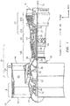
- FIG. 1 is a side cutaway illustration of a geared turbine engine 10.
- This turbine engine 10 extends along an axial centerline 12 between an upstream airflow inlet 14 and a downstream airflow exhaust 16.
- the turbine engine 10 includes a fan section 18, a compressor section 19, a combustor section 20 and a turbine section 21.
- the compressor section 19 includes a low pressure compressor (LPC) section 19A and a high pressure compressor (HPC) section 19B.
- the turbine section 21 includes a high pressure turbine (HPT) section 21A and a low pressure turbine (LPT) section 21B.
- the engine sections 18-21 are arranged sequentially along the centerline 12 within an engine housing 22.
- Each of the engine sections 18-19B, 21A and 21B includes a respective rotor 24-28.
- Each of these rotors 24-28 includes a plurality of rotor blades arranged circumferentially around and connected to one or more respective rotor disks.
- the rotor blades may be formed integral with or mechanically fastened, welded, brazed, adhered and/or otherwise attached to the respective rotor disk(s).
- the fan rotor 24 is connected to a gear train 30, for example, through a fan shaft 32.
- the gear train 30 and the LPC rotor 25 are connected to and driven by the LPT rotor 28 through a low speed shaft 33.
- the HPC rotor 26 is connected to and driven by the HPT rotor 27 through a high speed shaft 34.
- the shafts 32-34 are rotatably supported by a plurality of bearings 36; e.g., rolling element and/or thrust bearings. Each of these bearings 36 is connected to the engine housing 22 by at least one stationary structure such as, for example, an annular support strut.
- the air within the core gas path 38 may be referred to as "core air”.
- the air within the bypass gas path 40 may be referred to as "bypass air”.
- the core air is directed through the engine sections 19-21, and exits the turbine engine 10 through the airflow exhaust 16 to provide forward engine thrust.
- fuel is injected into a combustion chamber 42 and mixed with compressed core air. This fuel-core air mixture is ignited to power the turbine engine 10.
- the bypass air is directed through the bypass gas path 40 and out of the turbine engine 10 through a bypass nozzle 44 to provide additional forward engine thrust. This additional forward engine thrust may account for a majority (e.g., more than 70 percent) of total engine thrust.
- at least some of the bypass air may be directed out of the turbine engine 10 through a thrust reverser to provide reverse engine thrust.
- FIG. 1 represents one possible configuration for an engine 10. Aspects of the disclosure may be applied in connection with other environments, including additional configurations for gas turbine engines. Aspects of the disclosure may be applied in connection with non-geared engines.
- a system architecture 200 of an engine (e.g., the engine 10 of FIG. 1 ) is shown.
- the system 200 may be associated with one or more portions of the engine, such as for example a stage of a compressor section of the engine.
- the system 200 is shown as including structures 202a and 202b.
- the structure 202a may be a fixed structure/stator and the structure 202b may be a guide vane.
- the axially-oriented gap/cavity 206 between the structures 202a and 202b may accommodate a blade and an associated rotor or an integrally bladed rotor (IBR).
- An outer air seal 210 may be substantially axially located between the structures 202a and 202b.
- the seal 210 (e.g., a flange 212 of the seal 210 that projects radially outward) may be coupled to an aft seal ring 216.
- the aft seal ring 216 may be radially and/or axially coupled to an inner diffuser case at the aft end via one or more coupling techniques (e.g., interference fit, use of a bolt, etc.).
- the aft seal ring 216 may be coupled to a clearance control thermal ring (CCTR) 220.
- a bolt 228 and a nut 234 may be used for coupling (e.g., attaching) the CCTR 220 and the flange 212 to one another as shown in FIG. 2 .
- the bolt 228 may axially attach the aft seal ring 216 to the seal 210/flange 212 and a shim may be sandwiched between them.
- the aft seal ring 216 may be radially coupled to the seal 210 via a radial interference fit or any other type of radial coupling (e.g., radial attachment); the location of the radial coupling may occur where the aft seal ring 216 physically meets the seal 210 at the inner diameter of the flange 212.
- the CCTR 220 may be composed of two or more legs, such as for example a first leg 220a and a second leg 220b.
- the first leg 220a may be oriented substantially radially and the second leg 220b may be oriented substantially axially with respect to the axial centerline 12 ( FIG. 1 ) of the engine, such that the CCTR 220 may assume an L-shaped form factor.
- the blade (or the associated rotor) located in, e.g., the gap 206 may tend to grow and contract based on thermal loading over the various operational states of the engine.
- an excessive amount/degree of growth is experienced by the aft seal ring 216 then an excessively large radial gap may be formed between the blade and the seal 210, which may result in a loss of engine efficiency/performance.
- the growth of the blade/rotor can be substantially matched to the effective growth of the aft seal ring 216 then a compromise can be made between potential wear on the one hand and performance on the other hand.
- FIGS. 5A-5B a closer view of the interface between the leg 220a and the aft seal ring 216 is shown.
- a radial gap 504 may be defined between the first leg 220a of the CCTR 220 and the aft seal ring 216.
- the aft seal ring 216 may grow radially outward at a rate that is faster than a rate at which the first leg 220a grows.
- FIG. 5A a closer view of the interface between the leg 220a and the aft seal ring 216 is shown.
- a radial gap 504 may be defined between the first leg 220a of the CCTR 220 and the aft seal ring 216.
- the aft seal ring 216 may grow radially outward at a rate that is faster than a rate at which the first leg 220a grows.
- the aft seal ring 216 may eventually contact the (radially inward end) of the first leg 220a (e.g., the gap 504 may be zero in FIG. 5B ), such that any further radial outward growth of the aft seal ring 216 may be limited by the outward growth of the first leg 220a.
- FIGS. 2 and 5B illustrate the aft seal ring 216 contacting the CCTR 220 at the radially inward end of the first leg 220a (e.g., the gap 504 is radially inward of the CCTR 220)
- FIG. 2 illustrates a secondary location/gap 240 that can serve a similar purpose/function as the gap 504 described above.
- the gap 240 (which may be non-zero valued under loading that is less than a threshold and may be located radially outward of the aft seal ring 216) may be made equal to zero under (elevated) loads in a manner similar to the closing of the gap 504 in the transition from FIG. 5A to FIG. 5B described above.
- Use of the gap 240 may accommodate CCTR 220 materials that cannot be exposed to elevated temperatures.
- the rate at which the gap 504 (or the gap 240) decreases under thermal loading may be based on the materials that are used in the construction of one or more of the aft seal ring 216, the CCTR 220, the bolt 228, and the nut 234.
- the CCTR 220 may be made of a material that has a coefficient of thermal expansion that is less than a coefficient of thermal expansion associated with the aft seal ring 216.
- the aft seal ring 216 may be made of a first nickel-based alloy, such as Waspaloy ® alloy
- the CCTR 220 may be made of a second nickel-based alloy, such as Haynes ® 242 alloy or Incoloy ® 909 alloy.
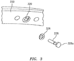
- the CCTR 220 may include one or more slotted bolt holes, such as for example a hole 320, for accommodating/seating the bolt 228.
- the hole 320 may allow the CCTR 220 to grow radially over the various operational states of the engine.
- a flat washer or sleeve, such as the washer 328, may be used to maintain a bearing surface with a head 328a of the bolt 228.
- FIG. 4 illustrates a plot 400 of the strain imposed on the hole 320 of FIG. 3 as a function of the gap (e.g., the gap 240 [ FIG. 2 ] or the gap 504 [ FIG. 5A ]) between the aft seal ring 216 and the CCTR 220.
- the gap e.g., the gap 240 [ FIG. 2 ] or the gap 504 [ FIG. 5A ]
- the gap increases the strain imposed on the hole 320 decreases.
- the gap is made too large then the performance benefit of maintaining a tight clearance between the rotating and stationary hardware provided by the use of the CCTR 220 will not be realized.
- a sealing arrangement that maintains a target tolerance in terms of clearance between rotating and stationary hardware.
- the use of a CCTR may limit an extent to which a seal ring is allowed to grow to maintain such a target clearance.
Abstract


Description
- Gas turbine engines, such as those which power aircraft and industrial equipment, employ a compressor to compress air that is drawn into the engine and a turbine to capture energy associated with the combustion of a fuel-air mixture. Clearances that are maintained between, e.g., rotating and static structure in the engine impact the performance and reliability of the engine. For example, in connection with the compressor, if the (radial) clearance between a blade tip and an engine case is too large there will be a loss of output performance/efficiency. On the other hand, if the clearance between the blade tip and the engine case is too small then the blade tip may rub against the engine case (or a seal disposed between the blade tip and the engine case), which may cause the components to wear over time.
- The clearance is a function of various parameters. For example, materials that are used in the construction of a component impact the rate of thermal growth/expansion of that component. Components that are closer to the engine centerline tend to be exposed to elevated temperatures relative to those components located further outward or radially distant from the centerline and hence tend to experience greater degrees of growth/deflection for a given material. Still further, the operative state of the engine (or the associated aircraft, where applicable) may impact the loads that a given component experiences at a given point in time; for example, an increase in load may be experienced by a component during acceleration relative to a steady state operation.
- In short, what is needed are techniques to control the degree of growth/expansion of a component under various loads (e.g., thermal loads) in order to be able to tailor a profile of a clearance over various operative states of an engine.
- The following presents a simplified summary in order to provide a basic understanding of some aspects of the disclosure. The summary is not an extensive overview of the disclosure. It is neither intended to identify key or critical elements of the disclosure nor to delineate the scope of the disclosure. The following summary merely presents some concepts of the disclosure in a simplified form as a prelude to the description below.
- Aspects of the disclosure are directed to a system of an engine, comprising: a clearance control thermal ring, and a seal ring, where a radial gap with respect to an axial centerline of the engine is formed between a radial end of the clearance control thermal ring and a facing radial surface of the seal ring, where the clearance control thermal ring is made of a first material and the seal ring is made of a second material that is different from the first material, and where a first coefficient of thermal expansion of the first material is less than a second coefficient of thermal expansion of the second material.
- In some embodiments, the clearance control thermal ring and the seal ring define a first radial gap during a first loading condition.
- In some embodiments, the first loading condition is associated with a steady state operation of the engine.
- In some embodiments, the radial gap is located radially inward of the clearance control thermal ring.
- In some embodiments, the radial gap is located radially outward of the seal ring.
- In some embodiments, the clearance control thermal ring and the seal ring are in contact with one another during a second loading condition.
- In some embodiments, the second loading condition is associated with acceleration of the engine.
- In some embodiments, the first material is a first nickel-based alloy and the second material is a second nickel-based alloy.
- In some embodiments, the first material includes at least one of Haynes® 242 alloy or Incoloy® 909 alloy and the second material includes Waspaloy® alloy.
- In some embodiments, the system further comprises a seal coupled to the clearance control thermal ring.
- In some embodiments, the seal includes a flange, the system comprising: a bolt and a nut that connect the clearance control thermal ring to the flange.
- In some embodiments, the clearance control thermal ring includes a slotted hole that seats the bolt.
- In some embodiments, the system further comprises at least one of a washer or a sleeve disposed between the clearance control thermal ring and a head of the bolt.
- In some embodiments, the seal is coupled to a stator at an axially forward end of the seal and a guide vane at an axially aft end of the seal.
- In some embodiments, the clearance control thermal ring includes a first leg and a second leg.
- In some embodiments, the first leg is substantially oriented in a radial direction and the second leg is substantially oriented in an axial direction.
- In some embodiments, the clearance control thermal ring is substantially L-shaped.
- Aspects of the disclosure are directed to an apparatus comprising: a clearance control thermal ring, a seal ring, and a bolt and a nut that attach the clearance control thermal ring to the seal ring, where the clearance control thermal ring and the seal ring form at least one radial gap with respect to an axial centerline of an engine during a first loading condition, and where the clearance control thermal ring and the seal ring have respective first and second coefficients of thermal expansion that are different from one another such that the at least one radial gap is closed during a second loading condition that is different from the first loading condition.
- In some embodiments, the at least one radial gap is located radially inward of the clearance control thermal ring.
- The present disclosure is illustrated by way of example and not limited in the accompanying figures in which like reference numerals indicate similar elements. The drawings are not necessarily drawn to scale unless specifically indicated otherwise.
-
FIG. 1 is a side cutaway illustration of a geared turbine engine. -
FIG. 2 illustrates an architecture incorporating a clearance control thermal ring coupled to a flange of a seal. -
FIG. 3 illustrates a clearance control thermal ring with a slotted radial hole. -
FIG. 4 illustrates a plot of stress on bolt holes of a clearance control thermal ring. -
FIGS. 5A-5B illustrate interfaces between a leg of a clearance control thermal ring and an aft seal ring. - It is noted that various connections are set forth between elements in the following description and in the drawings (the contents of which are included in this disclosure by way of reference). It is noted that these connections are general and, unless specified otherwise, may be direct or indirect and that this specification is not intended to be limiting in this respect. A coupling between two or more entities may refer to a direct connection or an indirect connection. An indirect connection may incorporate one or more intervening entities.
- In accordance with aspects of the disclosure, apparatuses, systems, and methods are directed to a clearance control thermal ring. The clearance control thermal ring may be coupled to a flange, such as for example a flange of an outer air seal. The clearance control thermal ring may control thermal growth of an aft seal ring. For example, the clearance control thermal ring may limit continued thermal growth of an aft seal ring beyond a threshold, thereby providing for a tailoring in terms of a clearance profile.
- Aspects of the disclosure may be applied in connection with a gas turbine engine.
FIG. 1 is a side cutaway illustration of a gearedturbine engine 10. Thisturbine engine 10 extends along anaxial centerline 12 between anupstream airflow inlet 14 and adownstream airflow exhaust 16. Theturbine engine 10 includes afan section 18, acompressor section 19, acombustor section 20 and aturbine section 21. Thecompressor section 19 includes a low pressure compressor (LPC)section 19A and a high pressure compressor (HPC)section 19B. Theturbine section 21 includes a high pressure turbine (HPT)section 21A and a low pressure turbine (LPT)section 21B. - The engine sections 18-21 are arranged sequentially along the
centerline 12 within anengine housing 22. Each of the engine sections 18-19B, 21A and 21B includes a respective rotor 24-28. Each of these rotors 24-28 includes a plurality of rotor blades arranged circumferentially around and connected to one or more respective rotor disks. The rotor blades, for example, may be formed integral with or mechanically fastened, welded, brazed, adhered and/or otherwise attached to the respective rotor disk(s). - The
fan rotor 24 is connected to agear train 30, for example, through afan shaft 32. Thegear train 30 and theLPC rotor 25 are connected to and driven by theLPT rotor 28 through alow speed shaft 33. TheHPC rotor 26 is connected to and driven by theHPT rotor 27 through ahigh speed shaft 34. The shafts 32-34 are rotatably supported by a plurality ofbearings 36; e.g., rolling element and/or thrust bearings. Each of thesebearings 36 is connected to theengine housing 22 by at least one stationary structure such as, for example, an annular support strut. - During operation, air enters the
turbine engine 10 through theairflow inlet 14, and is directed through thefan section 18 and into acore gas path 38 and abypass gas path 40. The air within thecore gas path 38 may be referred to as "core air". The air within thebypass gas path 40 may be referred to as "bypass air". The core air is directed through the engine sections 19-21, and exits theturbine engine 10 through theairflow exhaust 16 to provide forward engine thrust. Within thecombustor section 20, fuel is injected into acombustion chamber 42 and mixed with compressed core air. This fuel-core air mixture is ignited to power theturbine engine 10. The bypass air is directed through thebypass gas path 40 and out of theturbine engine 10 through abypass nozzle 44 to provide additional forward engine thrust. This additional forward engine thrust may account for a majority (e.g., more than 70 percent) of total engine thrust. Alternatively, at least some of the bypass air may be directed out of theturbine engine 10 through a thrust reverser to provide reverse engine thrust. -
FIG. 1 represents one possible configuration for anengine 10. Aspects of the disclosure may be applied in connection with other environments, including additional configurations for gas turbine engines. Aspects of the disclosure may be applied in connection with non-geared engines. - Referring to
FIG. 2 , asystem architecture 200 of an engine (e.g., theengine 10 ofFIG. 1 ) is shown. Thesystem 200 may be associated with one or more portions of the engine, such as for example a stage of a compressor section of the engine. - The
system 200 is shown as includingstructures structure 202a may be a fixed structure/stator and thestructure 202b may be a guide vane. The axially-oriented gap/cavity 206 between thestructures outer air seal 210 may be substantially axially located between thestructures - The seal 210 (e.g., a
flange 212 of theseal 210 that projects radially outward) may be coupled to anaft seal ring 216. Theaft seal ring 216 may be radially and/or axially coupled to an inner diffuser case at the aft end via one or more coupling techniques (e.g., interference fit, use of a bolt, etc.). Theaft seal ring 216 may be coupled to a clearance control thermal ring (CCTR) 220. Abolt 228 and anut 234 may be used for coupling (e.g., attaching) theCCTR 220 and theflange 212 to one another as shown inFIG. 2 . In some embodiments, thebolt 228 may axially attach theaft seal ring 216 to theseal 210/flange 212 and a shim may be sandwiched between them. In some embodiments, theaft seal ring 216 may be radially coupled to theseal 210 via a radial interference fit or any other type of radial coupling (e.g., radial attachment); the location of the radial coupling may occur where theaft seal ring 216 physically meets theseal 210 at the inner diameter of theflange 212. - The
CCTR 220 may be composed of two or more legs, such as for example afirst leg 220a and asecond leg 220b. Thefirst leg 220a may be oriented substantially radially and thesecond leg 220b may be oriented substantially axially with respect to the axial centerline 12 (FIG. 1 ) of the engine, such that theCCTR 220 may assume an L-shaped form factor. - The blade (or the associated rotor) located in, e.g., the
gap 206 may tend to grow and contract based on thermal loading over the various operational states of the engine. To accommodate the radially outward growth, it may be desirable for theaft seal ring 216 to grow radially outward as well to prevent/minimize/reduce rubbing/wear between the blade and theseal 210. On the other hand, if an excessive amount/degree of growth is experienced by theaft seal ring 216 then an excessively large radial gap may be formed between the blade and theseal 210, which may result in a loss of engine efficiency/performance. Thus, if the growth of the blade/rotor can be substantially matched to the effective growth of theaft seal ring 216 then a compromise can be made between potential wear on the one hand and performance on the other hand. - Referring to
FIGS. 5A-5B , a closer view of the interface between theleg 220a and theaft seal ring 216 is shown. In particular, as shown inFIG. 5A , during steady state operations aradial gap 504 may be defined between thefirst leg 220a of theCCTR 220 and theaft seal ring 216. As the thermal loading increases, such as for example during aircraft acceleration, theaft seal ring 216 may grow radially outward at a rate that is faster than a rate at which thefirst leg 220a grows. As shown inFIG. 5B , due to this difference in rates of thermal growth, theaft seal ring 216 may eventually contact the (radially inward end) of thefirst leg 220a (e.g., thegap 504 may be zero inFIG. 5B ), such that any further radial outward growth of theaft seal ring 216 may be limited by the outward growth of thefirst leg 220a. - While
FIGS. 2 and5B illustrate theaft seal ring 216 contacting theCCTR 220 at the radially inward end of thefirst leg 220a (e.g., thegap 504 is radially inward of the CCTR 220),FIG. 2 illustrates a secondary location/gap 240 that can serve a similar purpose/function as thegap 504 described above. For example, the gap 240 (which may be non-zero valued under loading that is less than a threshold and may be located radially outward of the aft seal ring 216) may be made equal to zero under (elevated) loads in a manner similar to the closing of thegap 504 in the transition fromFIG. 5A to FIG. 5B described above. Use of the gap 240 (potentially in lieu of the gap 504) may accommodateCCTR 220 materials that cannot be exposed to elevated temperatures. - The rate at which the gap 504 (or the gap 240) decreases under thermal loading may be based on the materials that are used in the construction of one or more of the
aft seal ring 216, theCCTR 220, thebolt 228, and thenut 234. For example, theCCTR 220 may be made of a material that has a coefficient of thermal expansion that is less than a coefficient of thermal expansion associated with theaft seal ring 216. In an exemplary embodiment, theaft seal ring 216 may be made of a first nickel-based alloy, such as Waspaloy® alloy, whereas theCCTR 220 may be made of a second nickel-based alloy, such as Haynes® 242 alloy or Incoloy® 909 alloy. - Referring to
FIG. 3 , a closer view of theCCTR 220 in relation to thebolt 228 is shown. TheCCTR 220 may include one or more slotted bolt holes, such as for example ahole 320, for accommodating/seating thebolt 228. Thehole 320 may allow theCCTR 220 to grow radially over the various operational states of the engine. A flat washer or sleeve, such as thewasher 328, may be used to maintain a bearing surface with ahead 328a of thebolt 228. -
FIG. 4 illustrates aplot 400 of the strain imposed on thehole 320 ofFIG. 3 as a function of the gap (e.g., the gap 240 [FIG. 2 ] or the gap 504 [FIG. 5A ]) between theaft seal ring 216 and theCCTR 220. As reflected by the inverse relationship shown in theplot 400, as the gap increases the strain imposed on thehole 320 decreases. Of course, if the gap is made too large then the performance benefit of maintaining a tight clearance between the rotating and stationary hardware provided by the use of theCCTR 220 will not be realized. - Technical effects and benefits of this disclosure include a sealing arrangement that maintains a target tolerance in terms of clearance between rotating and stationary hardware. The use of a CCTR may limit an extent to which a seal ring is allowed to grow to maintain such a target clearance.
- Aspects of the disclosure have been described in terms of illustrative embodiments thereof. Numerous other embodiments, modifications, and variations within the scope of the appended claims will occur to persons of ordinary skill in the art from a review of this disclosure. For example, one of ordinary skill in the art will appreciate that the steps described in conjunction with the illustrative figures may be performed in other than the recited order, and that one or more steps illustrated may be optional in accordance with aspects of the disclosure. One or more features described in connection with a first embodiment may be combined with one or more features of one or more additional embodiments.
Claims (15)
- A system (200) of an engine (10), comprising:a clearance control thermal ring (220); anda seal ring (216),wherein a radial gap (240;504) with respect to an axial centerline (12) of the engine (10) is formed between a radial end of the clearance control thermal ring (220) and a facing radial surface of the seal ring (216),wherein the clearance control thermal ring (220) is made of a first material and the seal ring (216) is made of a second material that is different from the first material, andwherein a first coefficient of thermal expansion of the first material is less than a second coefficient of thermal expansion of the second material.
- The system of claim 1, wherein the clearance control thermal ring (220) and the seal ring (216) define a first radial gap (240;504) during a first loading condition.
- The system of claim 2, wherein the first loading condition is associated with a steady state operation of the engine (10).
- The system of any preceding claim, wherein the radial gap (240;504) is located radially inward of the clearance control thermal ring (220).
- The system of any preceding claim, wherein the radial gap (240;504) is located radially outward of the seal ring (216).
- The system of any of claims 2 to 5, wherein the clearance control thermal ring (220) and the seal ring (216) are in contact with one another during a second loading condition,wherein, optionally, the second loading condition is associated with acceleration of the engine (10).
- The system of any preceding claim, wherein the first material is a first nickel-based alloy and the second material is a second nickel-based alloy,wherein, optionally, the first material includes at least one of Haynes® 242 alloy or Incoloy® 909 alloy and the second material includes Waspaloy® alloy.
- The system of any preceding claim, further comprising:a seal (210) coupled to the clearance control thermal ring (220).
- The system of claim 8, wherein the seal (210) includes a flange (212), the system comprising:a bolt (228) and a nut (234) that connect the clearance control thermal ring (220) to the flange (212).
- The system of claim 9, wherein the clearance control thermal ring (220) includes a slotted hole (320) that seats the bolt (228), wherein the system, optionally, further comprises:at least one of a washer (328) or a sleeve disposed between the clearance control thermal ring (220) and a head (328a) of the bolt (228).
- The system of any of claims 8 to 10, wherein the seal (210) is coupled to a stator (202a) at an axially forward end of the seal (210) and a guide vane (202b) at an axially aft end of the seal (210).
- The system of any preceding claim, wherein the clearance control thermal ring (220) includes a first leg (220a) and a second leg (220b).
- The system of claim 12, wherein the first leg (220a) is substantially oriented in a radial direction and the second leg (220b) is substantially oriented in an axial direction.
- The system of claim 12 or 13, wherein the clearance control thermal ring (220) is substantially L-shaped.
- An apparatus (200) comprising:a clearance control thermal ring (220);a seal ring (216); anda bolt (228) and a nut (234) that attach the clearance control thermal ring (220) to the seal ring (216),wherein the clearance control thermal ring (220) and the seal ring (216) form at least one radial gap (240;504) with respect to an axial centerline (12) of an engine (10) during a first loading condition, andwherein the clearance control thermal ring (220) and the seal ring (216) have respective first and second coefficients of thermal expansion that are different from one another such that the at least one radial gap (240;504) is closed during a second loading condition that is different from the first loading condition,wherein, optionally, the at least one radial gap (240;504) is located radially inward of the clearance control thermal ring (220).
Applications Claiming Priority (1)
| Application Number | Priority Date | Filing Date | Title |
|---|---|---|---|
| US15/212,849 US10344769B2 (en) | 2016-07-18 | 2016-07-18 | Clearance control between rotating and stationary structures |
Publications (3)
| Publication Number | Publication Date |
|---|---|
| EP3309364A2 true EP3309364A2 (en) | 2018-04-18 |
| EP3309364A3 EP3309364A3 (en) | 2018-05-09 |
| EP3309364B1 EP3309364B1 (en) | 2021-09-08 |
Family
ID=59315523
Family Applications (1)
| Application Number | Title | Priority Date | Filing Date |
|---|---|---|---|
| EP17180835.5A Active EP3309364B1 (en) | 2016-07-18 | 2017-07-11 | System of an engine |
Country Status (2)
| Country | Link |
|---|---|
| US (1) | US10344769B2 (en) |
| EP (1) | EP3309364B1 (en) |
Family Cites Families (15)
| Publication number | Priority date | Publication date | Assignee | Title |
|---|---|---|---|---|
| US4363599A (en) | 1979-10-31 | 1982-12-14 | General Electric Company | Clearance control |
| US5154575A (en) | 1991-07-01 | 1992-10-13 | United Technologies Corporation | Thermal blade tip clearance control for gas turbine engines |
| US5205115A (en) | 1991-11-04 | 1993-04-27 | General Electric Company | Gas turbine engine case counterflow thermal control |
| FR2685936A1 (en) | 1992-01-08 | 1993-07-09 | Snecma | DEVICE FOR CONTROLLING THE GAMES OF A TURBOMACHINE COMPRESSOR HOUSING. |
| US6877952B2 (en) | 2002-09-09 | 2005-04-12 | Florida Turbine Technologies, Inc | Passive clearance control |
| US20040219011A1 (en) | 2003-05-02 | 2004-11-04 | General Electric Company | High pressure turbine elastic clearance control system and method |
| US7597537B2 (en) | 2005-12-16 | 2009-10-06 | General Electric Company | Thermal control of gas turbine engine rings for active clearance control |
| US8126628B2 (en) | 2007-08-03 | 2012-02-28 | General Electric Company | Aircraft gas turbine engine blade tip clearance control |
| FR2922589B1 (en) | 2007-10-22 | 2009-12-04 | Snecma | CONTROL OF THE AUBES SET IN A HIGH-PRESSURE TURBINE TURBINE |
| US8197197B2 (en) | 2009-01-08 | 2012-06-12 | General Electric Company | Method of matching thermal response rates between a stator and a rotor and fluidic thermal switch for use therewith |
| US9200530B2 (en) * | 2012-07-20 | 2015-12-01 | United Technologies Corporation | Radial position control of case supported structure |
| CN104956035B (en) | 2013-02-08 | 2017-07-28 | 通用电气公司 | Active clearance control system based on aspirator |
| WO2014143311A1 (en) * | 2013-03-14 | 2014-09-18 | Uskert Richard C | Turbine shrouds |
| WO2014200768A1 (en) | 2013-06-11 | 2014-12-18 | General Electric Company | Clearance control ring assembly |
| US9587517B2 (en) * | 2014-12-29 | 2017-03-07 | Rolls-Royce North American Technologies, Inc. | Blade track assembly with turbine tip clearance control |
-
2016
- 2016-07-18 US US15/212,849 patent/US10344769B2/en active Active
-
2017
- 2017-07-11 EP EP17180835.5A patent/EP3309364B1/en active Active
Non-Patent Citations (1)
| Title |
|---|
| None |
Also Published As
| Publication number | Publication date |
|---|---|
| US10344769B2 (en) | 2019-07-09 |
| EP3309364A3 (en) | 2018-05-09 |
| US20180017067A1 (en) | 2018-01-18 |
| EP3309364B1 (en) | 2021-09-08 |
Similar Documents
| Publication | Publication Date | Title |
|---|---|---|
| CN110475955B (en) | Counter-rotating turbine with reversible reduction gearbox | |
| US11255207B2 (en) | Floating, non-contact seal and dimensions thereof | |
| US10370996B2 (en) | Floating, non-contact seal with offset build clearance for load imbalance | |
| US10641180B2 (en) | Hydrostatic non-contact seal with varied thickness beams | |
| US10024183B2 (en) | Gas turbine engine rotor disk-seal arrangement | |
| EP3090140A1 (en) | Blade outer air seal with secondary air sealing | |
| EP3502421A1 (en) | A gas turbine engine triple bend finger seal | |
| US11143048B2 (en) | Labyrinth seal with variable tooth heights | |
| EP3312394B1 (en) | Engine cases and associated flange | |
| US10533446B2 (en) | Alternative W-seal groove arrangement | |
| US10215037B2 (en) | Contoured retaining ring | |
| EP3309364B1 (en) | System of an engine | |
| US10612409B2 (en) | Active clearance control collector to manifold insert | |
| EP3663538B1 (en) | Rotor overspeed protection assembly | |
| US10408074B2 (en) | Creep resistant axial ring seal | |
| US11421557B1 (en) | Turbomachine components including castellation flanges and methods for coupling turbomachine components | |
| US10036503B2 (en) | Shim to maintain gap during engine assembly |
Legal Events
| Date | Code | Title | Description |
|---|---|---|---|
| PUAI | Public reference made under article 153(3) epc to a published international application that has entered the european phase |
Free format text: ORIGINAL CODE: 0009012 |
|
| STAA | Information on the status of an ep patent application or granted ep patent |
Free format text: STATUS: THE APPLICATION HAS BEEN PUBLISHED |
|
| PUAL | Search report despatched |
Free format text: ORIGINAL CODE: 0009013 |
|
| AK | Designated contracting states |
Kind code of ref document: A2 Designated state(s): AL AT BE BG CH CY CZ DE DK EE ES FI FR GB GR HR HU IE IS IT LI LT LU LV MC MK MT NL NO PL PT RO RS SE SI SK SM TR |
|
| AX | Request for extension of the european patent |
Extension state: BA ME |
|
| AK | Designated contracting states |
Kind code of ref document: A3 Designated state(s): AL AT BE BG CH CY CZ DE DK EE ES FI FR GB GR HR HU IE IS IT LI LT LU LV MC MK MT NL NO PL PT RO RS SE SI SK SM TR |
|
| AX | Request for extension of the european patent |
Extension state: BA ME |
|
| RIC1 | Information provided on ipc code assigned before grant |
Ipc: F01D 25/24 20060101ALI20180405BHEP Ipc: F01D 11/18 20060101AFI20180405BHEP |
|
| STAA | Information on the status of an ep patent application or granted ep patent |
Free format text: STATUS: REQUEST FOR EXAMINATION WAS MADE |
|
| 17P | Request for examination filed |
Effective date: 20181109 |
|
| RBV | Designated contracting states (corrected) |
Designated state(s): AL AT BE BG CH CY CZ DE DK EE ES FI FR GB GR HR HU IE IS IT LI LT LU LV MC MK MT NL NO PL PT RO RS SE SI SK SM TR |
|
| STAA | Information on the status of an ep patent application or granted ep patent |
Free format text: STATUS: REQUEST FOR EXAMINATION WAS MADE |
|
| GRAP | Despatch of communication of intention to grant a patent |
Free format text: ORIGINAL CODE: EPIDOSNIGR1 |
|
| STAA | Information on the status of an ep patent application or granted ep patent |
Free format text: STATUS: GRANT OF PATENT IS INTENDED |
|
| RAP1 | Party data changed (applicant data changed or rights of an application transferred) |
Owner name: RAYTHEON TECHNOLOGIES CORPORATION |
|
| INTG | Intention to grant announced |
Effective date: 20210324 |
|
| GRAS | Grant fee paid |
Free format text: ORIGINAL CODE: EPIDOSNIGR3 |
|
| GRAA | (expected) grant |
Free format text: ORIGINAL CODE: 0009210 |
|
| STAA | Information on the status of an ep patent application or granted ep patent |
Free format text: STATUS: THE PATENT HAS BEEN GRANTED |
|
| AK | Designated contracting states |
Kind code of ref document: B1 Designated state(s): AL AT BE BG CH CY CZ DE DK EE ES FI FR GB GR HR HU IE IS IT LI LT LU LV MC MK MT NL NO PL PT RO RS SE SI SK SM TR |
|
| REG | Reference to a national code |
Ref country code: GB Ref legal event code: FG4D |
|
| REG | Reference to a national code |
Ref country code: AT Ref legal event code: REF Ref document number: 1428778 Country of ref document: AT Kind code of ref document: T Effective date: 20210915 Ref country code: CH Ref legal event code: EP |
|
| REG | Reference to a national code |
Ref country code: IE Ref legal event code: FG4D |
|
| REG | Reference to a national code |
Ref country code: DE Ref legal event code: R096 Ref document number: 602017045564 Country of ref document: DE |
|
| REG | Reference to a national code |
Ref country code: LT Ref legal event code: MG9D |
|
| REG | Reference to a national code |
Ref country code: NL Ref legal event code: MP Effective date: 20210908 |
|
| PG25 | Lapsed in a contracting state [announced via postgrant information from national office to epo] |
Ref country code: RS Free format text: LAPSE BECAUSE OF FAILURE TO SUBMIT A TRANSLATION OF THE DESCRIPTION OR TO PAY THE FEE WITHIN THE PRESCRIBED TIME-LIMIT Effective date: 20210908 Ref country code: SE Free format text: LAPSE BECAUSE OF FAILURE TO SUBMIT A TRANSLATION OF THE DESCRIPTION OR TO PAY THE FEE WITHIN THE PRESCRIBED TIME-LIMIT Effective date: 20210908 Ref country code: FI Free format text: LAPSE BECAUSE OF FAILURE TO SUBMIT A TRANSLATION OF THE DESCRIPTION OR TO PAY THE FEE WITHIN THE PRESCRIBED TIME-LIMIT Effective date: 20210908 Ref country code: ES Free format text: LAPSE BECAUSE OF FAILURE TO SUBMIT A TRANSLATION OF THE DESCRIPTION OR TO PAY THE FEE WITHIN THE PRESCRIBED TIME-LIMIT Effective date: 20210908 Ref country code: HR Free format text: LAPSE BECAUSE OF FAILURE TO SUBMIT A TRANSLATION OF THE DESCRIPTION OR TO PAY THE FEE WITHIN THE PRESCRIBED TIME-LIMIT Effective date: 20210908 Ref country code: NO Free format text: LAPSE BECAUSE OF FAILURE TO SUBMIT A TRANSLATION OF THE DESCRIPTION OR TO PAY THE FEE WITHIN THE PRESCRIBED TIME-LIMIT Effective date: 20211208 Ref country code: BG Free format text: LAPSE BECAUSE OF FAILURE TO SUBMIT A TRANSLATION OF THE DESCRIPTION OR TO PAY THE FEE WITHIN THE PRESCRIBED TIME-LIMIT Effective date: 20211208 Ref country code: LT Free format text: LAPSE BECAUSE OF FAILURE TO SUBMIT A TRANSLATION OF THE DESCRIPTION OR TO PAY THE FEE WITHIN THE PRESCRIBED TIME-LIMIT Effective date: 20210908 |
|
| REG | Reference to a national code |
Ref country code: AT Ref legal event code: MK05 Ref document number: 1428778 Country of ref document: AT Kind code of ref document: T Effective date: 20210908 |
|
| PG25 | Lapsed in a contracting state [announced via postgrant information from national office to epo] |
Ref country code: LV Free format text: LAPSE BECAUSE OF FAILURE TO SUBMIT A TRANSLATION OF THE DESCRIPTION OR TO PAY THE FEE WITHIN THE PRESCRIBED TIME-LIMIT Effective date: 20210908 Ref country code: GR Free format text: LAPSE BECAUSE OF FAILURE TO SUBMIT A TRANSLATION OF THE DESCRIPTION OR TO PAY THE FEE WITHIN THE PRESCRIBED TIME-LIMIT Effective date: 20211209 |
|
| PG25 | Lapsed in a contracting state [announced via postgrant information from national office to epo] |
Ref country code: AT Free format text: LAPSE BECAUSE OF FAILURE TO SUBMIT A TRANSLATION OF THE DESCRIPTION OR TO PAY THE FEE WITHIN THE PRESCRIBED TIME-LIMIT Effective date: 20210908 |
|
| PG25 | Lapsed in a contracting state [announced via postgrant information from national office to epo] |
Ref country code: IS Free format text: LAPSE BECAUSE OF FAILURE TO SUBMIT A TRANSLATION OF THE DESCRIPTION OR TO PAY THE FEE WITHIN THE PRESCRIBED TIME-LIMIT Effective date: 20220108 Ref country code: SM Free format text: LAPSE BECAUSE OF FAILURE TO SUBMIT A TRANSLATION OF THE DESCRIPTION OR TO PAY THE FEE WITHIN THE PRESCRIBED TIME-LIMIT Effective date: 20210908 Ref country code: SK Free format text: LAPSE BECAUSE OF FAILURE TO SUBMIT A TRANSLATION OF THE DESCRIPTION OR TO PAY THE FEE WITHIN THE PRESCRIBED TIME-LIMIT Effective date: 20210908 Ref country code: RO Free format text: LAPSE BECAUSE OF FAILURE TO SUBMIT A TRANSLATION OF THE DESCRIPTION OR TO PAY THE FEE WITHIN THE PRESCRIBED TIME-LIMIT Effective date: 20210908 Ref country code: PT Free format text: LAPSE BECAUSE OF FAILURE TO SUBMIT A TRANSLATION OF THE DESCRIPTION OR TO PAY THE FEE WITHIN THE PRESCRIBED TIME-LIMIT Effective date: 20220110 Ref country code: PL Free format text: LAPSE BECAUSE OF FAILURE TO SUBMIT A TRANSLATION OF THE DESCRIPTION OR TO PAY THE FEE WITHIN THE PRESCRIBED TIME-LIMIT Effective date: 20210908 Ref country code: NL Free format text: LAPSE BECAUSE OF FAILURE TO SUBMIT A TRANSLATION OF THE DESCRIPTION OR TO PAY THE FEE WITHIN THE PRESCRIBED TIME-LIMIT Effective date: 20210908 Ref country code: EE Free format text: LAPSE BECAUSE OF FAILURE TO SUBMIT A TRANSLATION OF THE DESCRIPTION OR TO PAY THE FEE WITHIN THE PRESCRIBED TIME-LIMIT Effective date: 20210908 Ref country code: CZ Free format text: LAPSE BECAUSE OF FAILURE TO SUBMIT A TRANSLATION OF THE DESCRIPTION OR TO PAY THE FEE WITHIN THE PRESCRIBED TIME-LIMIT Effective date: 20210908 Ref country code: AL Free format text: LAPSE BECAUSE OF FAILURE TO SUBMIT A TRANSLATION OF THE DESCRIPTION OR TO PAY THE FEE WITHIN THE PRESCRIBED TIME-LIMIT Effective date: 20210908 |
|
| REG | Reference to a national code |
Ref country code: DE Ref legal event code: R097 Ref document number: 602017045564 Country of ref document: DE |
|
| PLBE | No opposition filed within time limit |
Free format text: ORIGINAL CODE: 0009261 |
|
| STAA | Information on the status of an ep patent application or granted ep patent |
Free format text: STATUS: NO OPPOSITION FILED WITHIN TIME LIMIT |
|
| PG25 | Lapsed in a contracting state [announced via postgrant information from national office to epo] |
Ref country code: DK Free format text: LAPSE BECAUSE OF FAILURE TO SUBMIT A TRANSLATION OF THE DESCRIPTION OR TO PAY THE FEE WITHIN THE PRESCRIBED TIME-LIMIT Effective date: 20210908 |
|
| 26N | No opposition filed |
Effective date: 20220609 |
|
| PG25 | Lapsed in a contracting state [announced via postgrant information from national office to epo] |
Ref country code: SI Free format text: LAPSE BECAUSE OF FAILURE TO SUBMIT A TRANSLATION OF THE DESCRIPTION OR TO PAY THE FEE WITHIN THE PRESCRIBED TIME-LIMIT Effective date: 20210908 |
|
| PG25 | Lapsed in a contracting state [announced via postgrant information from national office to epo] |
Ref country code: IT Free format text: LAPSE BECAUSE OF FAILURE TO SUBMIT A TRANSLATION OF THE DESCRIPTION OR TO PAY THE FEE WITHIN THE PRESCRIBED TIME-LIMIT Effective date: 20210908 |
|
| PG25 | Lapsed in a contracting state [announced via postgrant information from national office to epo] |
Ref country code: MC Free format text: LAPSE BECAUSE OF FAILURE TO SUBMIT A TRANSLATION OF THE DESCRIPTION OR TO PAY THE FEE WITHIN THE PRESCRIBED TIME-LIMIT Effective date: 20210908 |
|
| REG | Reference to a national code |
Ref country code: CH Ref legal event code: PL |
|
| REG | Reference to a national code |
Ref country code: BE Ref legal event code: MM Effective date: 20220731 |
|
| PG25 | Lapsed in a contracting state [announced via postgrant information from national office to epo] |
Ref country code: LU Free format text: LAPSE BECAUSE OF NON-PAYMENT OF DUE FEES Effective date: 20220711 Ref country code: LI Free format text: LAPSE BECAUSE OF NON-PAYMENT OF DUE FEES Effective date: 20220731 Ref country code: CH Free format text: LAPSE BECAUSE OF NON-PAYMENT OF DUE FEES Effective date: 20220731 |
|
| PG25 | Lapsed in a contracting state [announced via postgrant information from national office to epo] |
Ref country code: BE Free format text: LAPSE BECAUSE OF NON-PAYMENT OF DUE FEES Effective date: 20220731 |
|
| P01 | Opt-out of the competence of the unified patent court (upc) registered |
Effective date: 20230520 |
|
| PG25 | Lapsed in a contracting state [announced via postgrant information from national office to epo] |
Ref country code: IE Free format text: LAPSE BECAUSE OF NON-PAYMENT OF DUE FEES Effective date: 20220711 |
|
| PGFP | Annual fee paid to national office [announced via postgrant information from national office to epo] |
Ref country code: FR Payment date: 20230621 Year of fee payment: 7 |
|
| PGFP | Annual fee paid to national office [announced via postgrant information from national office to epo] |
Ref country code: GB Payment date: 20230620 Year of fee payment: 7 |
|
| PGFP | Annual fee paid to national office [announced via postgrant information from national office to epo] |
Ref country code: DE Payment date: 20230620 Year of fee payment: 7 |
|
| PG25 | Lapsed in a contracting state [announced via postgrant information from national office to epo] |
Ref country code: HU Free format text: LAPSE BECAUSE OF FAILURE TO SUBMIT A TRANSLATION OF THE DESCRIPTION OR TO PAY THE FEE WITHIN THE PRESCRIBED TIME-LIMIT; INVALID AB INITIO Effective date: 20170711 |