EP3438409B1 - Kettenförderer und antriebskettenrad dafür - Google Patents
Kettenförderer und antriebskettenrad dafür Download PDFInfo
- Publication number
- EP3438409B1 EP3438409B1 EP18187049.4A EP18187049A EP3438409B1 EP 3438409 B1 EP3438409 B1 EP 3438409B1 EP 18187049 A EP18187049 A EP 18187049A EP 3438409 B1 EP3438409 B1 EP 3438409B1
- Authority
- EP
- European Patent Office
- Prior art keywords
- chains
- flight
- conveyor assembly
- chain
- central axis
- Prior art date
- Legal status (The legal status is an assumption and is not a legal conclusion. Google has not performed a legal analysis and makes no representation as to the accuracy of the status listed.)
- Not-in-force
Links
- 239000000463 material Substances 0.000 claims description 24
- 230000010006 flight Effects 0.000 claims description 21
- 238000005065 mining Methods 0.000 description 8
- 230000033001 locomotion Effects 0.000 description 6
- 230000002093 peripheral effect Effects 0.000 description 2
- 239000003245 coal Substances 0.000 description 1
- 238000010276 construction Methods 0.000 description 1
- 230000008878 coupling Effects 0.000 description 1
- 238000010168 coupling process Methods 0.000 description 1
- 238000005859 coupling reaction Methods 0.000 description 1
- 230000001419 dependent effect Effects 0.000 description 1
- 229910052500 inorganic mineral Inorganic materials 0.000 description 1
- 239000011707 mineral Substances 0.000 description 1
- 230000004048 modification Effects 0.000 description 1
- 238000012986 modification Methods 0.000 description 1
Images




Classifications
-
- B—PERFORMING OPERATIONS; TRANSPORTING
- B65—CONVEYING; PACKING; STORING; HANDLING THIN OR FILAMENTARY MATERIAL
- B65G—TRANSPORT OR STORAGE DEVICES, e.g. CONVEYORS FOR LOADING OR TIPPING, SHOP CONVEYOR SYSTEMS OR PNEUMATIC TUBE CONVEYORS
- B65G17/00—Conveyors having an endless traction element, e.g. a chain, transmitting movement to a continuous or substantially-continuous load-carrying surface or to a series of individual load-carriers; Endless-chain conveyors in which the chains form the load-carrying surface
- B65G17/06—Conveyors having an endless traction element, e.g. a chain, transmitting movement to a continuous or substantially-continuous load-carrying surface or to a series of individual load-carriers; Endless-chain conveyors in which the chains form the load-carrying surface having a load-carrying surface formed by a series of interconnected, e.g. longitudinal, links, plates, or platforms
- B65G17/063—Conveyors having an endless traction element, e.g. a chain, transmitting movement to a continuous or substantially-continuous load-carrying surface or to a series of individual load-carriers; Endless-chain conveyors in which the chains form the load-carrying surface having a load-carrying surface formed by a series of interconnected, e.g. longitudinal, links, plates, or platforms the load carrying surface being formed by profiles, rods, bars, rollers or the like attached to more than one traction element
-
- B—PERFORMING OPERATIONS; TRANSPORTING
- B65—CONVEYING; PACKING; STORING; HANDLING THIN OR FILAMENTARY MATERIAL
- B65G—TRANSPORT OR STORAGE DEVICES, e.g. CONVEYORS FOR LOADING OR TIPPING, SHOP CONVEYOR SYSTEMS OR PNEUMATIC TUBE CONVEYORS
- B65G19/00—Conveyors comprising an impeller or a series of impellers carried by an endless traction element and arranged to move articles or materials over a supporting surface or underlying material, e.g. endless scraper conveyors
- B65G19/18—Details
- B65G19/20—Traction chains, ropes, or cables
-
- B—PERFORMING OPERATIONS; TRANSPORTING
- B65—CONVEYING; PACKING; STORING; HANDLING THIN OR FILAMENTARY MATERIAL
- B65G—TRANSPORT OR STORAGE DEVICES, e.g. CONVEYORS FOR LOADING OR TIPPING, SHOP CONVEYOR SYSTEMS OR PNEUMATIC TUBE CONVEYORS
- B65G17/00—Conveyors having an endless traction element, e.g. a chain, transmitting movement to a continuous or substantially-continuous load-carrying surface or to a series of individual load-carriers; Endless-chain conveyors in which the chains form the load-carrying surface
- B65G17/30—Details; Auxiliary devices
- B65G17/38—Chains or like traction elements; Connections between traction elements and load-carriers
- B65G17/42—Attaching load carriers to traction elements
-
- B—PERFORMING OPERATIONS; TRANSPORTING
- B65—CONVEYING; PACKING; STORING; HANDLING THIN OR FILAMENTARY MATERIAL
- B65G—TRANSPORT OR STORAGE DEVICES, e.g. CONVEYORS FOR LOADING OR TIPPING, SHOP CONVEYOR SYSTEMS OR PNEUMATIC TUBE CONVEYORS
- B65G19/00—Conveyors comprising an impeller or a series of impellers carried by an endless traction element and arranged to move articles or materials over a supporting surface or underlying material, e.g. endless scraper conveyors
- B65G19/04—Conveyors comprising an impeller or a series of impellers carried by an endless traction element and arranged to move articles or materials over a supporting surface or underlying material, e.g. endless scraper conveyors for moving bulk material in open troughs or channels
- B65G19/06—Conveyors comprising an impeller or a series of impellers carried by an endless traction element and arranged to move articles or materials over a supporting surface or underlying material, e.g. endless scraper conveyors for moving bulk material in open troughs or channels the impellers being scrapers similar in size and shape to the cross-section of the trough or channel
- B65G19/10—Conveyors comprising an impeller or a series of impellers carried by an endless traction element and arranged to move articles or materials over a supporting surface or underlying material, e.g. endless scraper conveyors for moving bulk material in open troughs or channels the impellers being scrapers similar in size and shape to the cross-section of the trough or channel and attached to a pair of belts, ropes or chains
-
- B—PERFORMING OPERATIONS; TRANSPORTING
- B65—CONVEYING; PACKING; STORING; HANDLING THIN OR FILAMENTARY MATERIAL
- B65G—TRANSPORT OR STORAGE DEVICES, e.g. CONVEYORS FOR LOADING OR TIPPING, SHOP CONVEYOR SYSTEMS OR PNEUMATIC TUBE CONVEYORS
- B65G19/00—Conveyors comprising an impeller or a series of impellers carried by an endless traction element and arranged to move articles or materials over a supporting surface or underlying material, e.g. endless scraper conveyors
- B65G19/18—Details
- B65G19/22—Impellers, e.g. push-plates, scrapers; Guiding means therefor
-
- B—PERFORMING OPERATIONS; TRANSPORTING
- B65—CONVEYING; PACKING; STORING; HANDLING THIN OR FILAMENTARY MATERIAL
- B65G—TRANSPORT OR STORAGE DEVICES, e.g. CONVEYORS FOR LOADING OR TIPPING, SHOP CONVEYOR SYSTEMS OR PNEUMATIC TUBE CONVEYORS
- B65G19/00—Conveyors comprising an impeller or a series of impellers carried by an endless traction element and arranged to move articles or materials over a supporting surface or underlying material, e.g. endless scraper conveyors
- B65G19/18—Details
- B65G19/22—Impellers, e.g. push-plates, scrapers; Guiding means therefor
- B65G19/24—Attachment of impellers to traction element
-
- B—PERFORMING OPERATIONS; TRANSPORTING
- B65—CONVEYING; PACKING; STORING; HANDLING THIN OR FILAMENTARY MATERIAL
- B65G—TRANSPORT OR STORAGE DEVICES, e.g. CONVEYORS FOR LOADING OR TIPPING, SHOP CONVEYOR SYSTEMS OR PNEUMATIC TUBE CONVEYORS
- B65G23/00—Driving gear for endless conveyors; Belt- or chain-tensioning arrangements
- B65G23/02—Belt- or chain-engaging elements
- B65G23/04—Drums, rollers, or wheels
- B65G23/06—Drums, rollers, or wheels with projections engaging abutments on belts or chains, e.g. sprocket wheels
-
- E—FIXED CONSTRUCTIONS
- E21—EARTH OR ROCK DRILLING; MINING
- E21C—MINING OR QUARRYING
- E21C27/00—Machines which completely free the mineral from the seam
- E21C27/02—Machines which completely free the mineral from the seam solely by slitting
-
- E—FIXED CONSTRUCTIONS
- E21—EARTH OR ROCK DRILLING; MINING
- E21F—SAFETY DEVICES, TRANSPORT, FILLING-UP, RESCUE, VENTILATION, OR DRAINING IN OR OF MINES OR TUNNELS
- E21F13/00—Transport specially adapted to underground conditions
-
- E—FIXED CONSTRUCTIONS
- E21—EARTH OR ROCK DRILLING; MINING
- E21F—SAFETY DEVICES, TRANSPORT, FILLING-UP, RESCUE, VENTILATION, OR DRAINING IN OR OF MINES OR TUNNELS
- E21F13/00—Transport specially adapted to underground conditions
- E21F13/06—Transport of mined material at or adjacent to the working face
-
- E—FIXED CONSTRUCTIONS
- E21—EARTH OR ROCK DRILLING; MINING
- E21F—SAFETY DEVICES, TRANSPORT, FILLING-UP, RESCUE, VENTILATION, OR DRAINING IN OR OF MINES OR TUNNELS
- E21F13/00—Transport specially adapted to underground conditions
- E21F13/06—Transport of mined material at or adjacent to the working face
- E21F13/066—Scraper chain conveyors
-
- B—PERFORMING OPERATIONS; TRANSPORTING
- B65—CONVEYING; PACKING; STORING; HANDLING THIN OR FILAMENTARY MATERIAL
- B65G—TRANSPORT OR STORAGE DEVICES, e.g. CONVEYORS FOR LOADING OR TIPPING, SHOP CONVEYOR SYSTEMS OR PNEUMATIC TUBE CONVEYORS
- B65G2201/00—Indexing codes relating to handling devices, e.g. conveyors, characterised by the type of product or load being conveyed or handled
- B65G2201/04—Bulk
- B65G2201/045—Sand, soil and mineral ore
-
- B—PERFORMING OPERATIONS; TRANSPORTING
- B65—CONVEYING; PACKING; STORING; HANDLING THIN OR FILAMENTARY MATERIAL
- B65G—TRANSPORT OR STORAGE DEVICES, e.g. CONVEYORS FOR LOADING OR TIPPING, SHOP CONVEYOR SYSTEMS OR PNEUMATIC TUBE CONVEYORS
- B65G2812/00—Indexing codes relating to the kind or type of conveyors
- B65G2812/02—Belt or chain conveyors
- B65G2812/02267—Conveyors having endless traction elements
- B65G2812/02277—Common features for chain conveyors
- B65G2812/02287—Driving means
-
- B—PERFORMING OPERATIONS; TRANSPORTING
- B65—CONVEYING; PACKING; STORING; HANDLING THIN OR FILAMENTARY MATERIAL
- B65G—TRANSPORT OR STORAGE DEVICES, e.g. CONVEYORS FOR LOADING OR TIPPING, SHOP CONVEYOR SYSTEMS OR PNEUMATIC TUBE CONVEYORS
- B65G2812/00—Indexing codes relating to the kind or type of conveyors
- B65G2812/02—Belt or chain conveyors
- B65G2812/02267—Conveyors having endless traction elements
- B65G2812/02277—Common features for chain conveyors
- B65G2812/02326—Chains, cables or the like
- B65G2812/02376—Chains, cables or the like characterised by the configuration
-
- B—PERFORMING OPERATIONS; TRANSPORTING
- B65—CONVEYING; PACKING; STORING; HANDLING THIN OR FILAMENTARY MATERIAL
- B65G—TRANSPORT OR STORAGE DEVICES, e.g. CONVEYORS FOR LOADING OR TIPPING, SHOP CONVEYOR SYSTEMS OR PNEUMATIC TUBE CONVEYORS
- B65G2812/00—Indexing codes relating to the kind or type of conveyors
- B65G2812/02—Belt or chain conveyors
- B65G2812/02267—Conveyors having endless traction elements
- B65G2812/02861—Conveyors having endless traction elements moving the materials over supporting surfaces by impeller means, e.g. scrapers
- B65G2812/02871—Conveyors having endless traction elements moving the materials over supporting surfaces by impeller means, e.g. scrapers for bulk material
- B65G2812/02881—Scraper conveyors
- B65G2812/0295—Scraper chains
- B65G2812/0296—Attachments of scrapers to traction elements
- B65G2812/0298—Attachments of scrapers to traction elements to more than one chain
-
- E—FIXED CONSTRUCTIONS
- E21—EARTH OR ROCK DRILLING; MINING
- E21C—MINING OR QUARRYING
- E21C25/00—Cutting machines, i.e. for making slits approximately parallel or perpendicular to the seam
- E21C25/16—Machines slitting solely by one or more rotating saws, cutting discs, or wheels
Definitions
- the present disclosure relates to conveyor systems, and particularly to a conveyor including flight bars (e.g., for a longwall mining system).
- a conveyor system configured to move material relative to a mine face
- the conveyor system comprising:a conveyor pan configured to support the material; a drive unit including a drive shaft and a plurality of sprockets secured to the drive shaft, the drive shaft driven about a rotational axis; and a conveying element including a plurality of chains and a plurality of flights, each of the chains driven by one of the sprockets to move the chain and the flights over the conveyor pan, each of the flights coupled between the plurality of chains, each of the plurality of flights including a first portion and a second portion, the first portion coupled to the second portion by a movable joint, the flights configured to move the material over the conveyor pan.
- Mining systems such as longwall mining systems, include one or more shearers having cutting drums for cutting material from a mine face.
- the material is deposited on an armored face conveyor (AFC) and carried away from the mine face.
- AFC armored face conveyor
- Each of the chains are driven by one of the sprockets to move the chain and the flights over the conveyor pan.
- Each of the flights is coupled between the plurality of chains.
- Each of the plurality of flights includes a first portion and a second portion. The first portion is coupled to the second portion by a movable joint, and the flights are configured to move the material over the conveyor pan.
- a conveyor assembly for moving material including at least two chains, and a plurality of flights.
- Each of the plurality of flights includes a first portion coupled to a second portion by a movable joint.
- the first portion is fixedly coupled to one of the at least two chains.
- the second portion extends between the at least two chains.
- the plurality of flights is configured to contact and move the material.
- a conveyor assembly for moving material includes at least two chains each defining a longitudinal axis, and a plurality of flights coupled to the at least two chains and configured to contact and move the material in a direction parallel to the longitudinal axes.
- Each of the plurality of flights extends along a central axis oriented oblique with respect to the longitudinal axes.
- Each flight includes a first portion offset from a second portion in a direction parallel to the longitudinal axes.
- FIG. 1 illustrates a mining machine, such as a longwall shearer 10, including a frame or chassis 14 and a pair of cutting heads 18 (i.e., first cutting head 18a and second cutting head 18b) having picks 22 ( FIG. 2 ) with the cutting heads 18 coupled to the chassis 14 by ranging arms 26 (i.e., first ranging arm 26a and second ranging arm 26b).
- the chassis 14 is configured to move or tram along a rack 30 relative to a mine face 34 ( FIG. 2 ) in a first direction 38 and a second direction 42 opposite the first direction 38.
- the first cutting head 18a is elevated for the picks 22 to cut material (e.g., coal or other minerals) from an upper portion of the mine face 34, while the second cutting head 18b is in a lower position for the picks 22 to cut material from a lower portion of the mine face 34.
- the cut material is then deposited onto a conveyor assembly 46, described in more detail below.
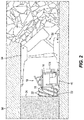
- a portion of a longwall mining system including the shearer 10, the conveyor assembly 46, and roof supports 50 that are operable to advance the shearer 10 and the conveyor assembly 46 toward the mine face 34.
- Each roof support 50 is positioned behind the conveyor assembly 46 (i.e., away from the mine face 34) and includes a shield 54 extending over the chassis 14 and the conveyor assembly 46 to engage a mine roof 58 ( FIG. 3 ).
- each end frame 98 includes a drive unit 102 having a motor 106, a drive shaft 110 defining a rotational axis 114 that is perpendicular to the directions 38, 42, and a plurality of sprockets 118 rotatably fixed to the drive shaft 110.
- the drive unit 102 includes three sprockets 118a, 118b, 118c ( FIG. 5 ); in other embodiments, the drive unit 102 may include fewer or more sprockets 118.
- each sprocket 118 includes teeth or protrusions 122 radially extending away from the rotational axis 114.
- each protrusion is formed as a pair of protrusions 122 and includes a forward surface 126 facing toward a direction of rotation, and a rear surface 130 facing in the opposite direction.
- a first link slot 134 is formed between adjacent pairs of protrusions 122 in a peripheral direction of the drive shaft 110 about the rotational axis 114 so that the first link slots 134 form circumferential gaps between adjacent pairs of protrusions 122.
- each first link slot 134 is formed between a forward surface 126 of one pair of protrusions 122 and a rear surface 130 of an adjacent pair of protrusions 122 in the peripheral direction of the drive shaft 110 ( FIGS. 4 and 5 ).
- each second link slot 138 is formed between a single pair of protrusions 122 ( FIG. 5 ).
- each second link slot 138 is formed between a first inner surface 139 and a second inner surface 140, which faces the first inner surface 139, of a single pair of protrusions 122 ( FIG. 5 ).
- each sprocket 118a-c is angularly offset about the rotational axis 114 relative to the other sprockets 118a-c.
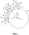
- a first rear surface 130a of the pair of protrusions 122 of the first sprocket 118a is spaced from a second rear surface 130b of the pair of protrusions 122 of the second sprocket 118b by a first angle 142 ( FIG. 9 ) in an angular direction about the rotational axis 114.
- the second rear surface 130b is spaced from a third rear surface 130c of the pair of protrusions 122 of the third sprocket 118c by a second angle 146 ( FIG. 9 ) in the angular direction about the rotational axis 114.
- the first angle 142 is the same as the second angle 146. In other embodiments, the first angle 142 may be greater than or less than the second angle 146.
- each sprocket 118 includes seven protrusions 122 (or pairs of protrusions) and three chains 182 are driven, providing first and second angles 142, 146 of about 17 degrees.
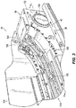
- the conveyor assembly 46 also includes a conveyor pan 150 positioned between the two end frames 98.
- the conveyor pan 150 is formed as multiple individual pan sections (only one pan section is illustrated in FIG 6 ) that are interconnected with one another.
- the illustrated conveyor pan 150 includes a support plate 154 that defines a lower channel 158 having two opposed lower grooves 162 and an upper channel 166 having two opposed upper grooves 170.
- the lower channel 158 is a closed channel to inhibit cut material and/or debris from entering the lower channel 158, whereas the upper channel 166 is an open channel for receiving the cut material.
- the conveyor pan 150 is coupled to the rack 30, and a spill plate 174 is positioned between the rack 30 and the roof support 50 ( FIG. 2 ).
- the conveyor assembly 46 further includes a conveying element 178 that is supported by the conveyor pan 150 and is driven by the two end frames 98.
- the illustrated conveying element 178 is a chain conveyor including at least two chains 182 and flight bars 186 (conventional flight bars are illustrated in FIG. 6 ) coupled between the chains 182 at regular intervals.
- the flight bars 186 may be removeably coupled to the chains 182 (e.g., the flight bars 186 are bolted to the chains 182) to facilitate replacement of the flight bars 186.
- Each chain 182 defines a longitudinal axis 190 extending in a plane that is perpendicular to the rotational axis 114 of the end frames 98.
- each chain 182 includes horizontal or first links 194 coupled to vertical or second links 198 (e.g., one horizontal link 194 is coupled between two adjacent vertical links 198) with the flight bars 186 coupled to the horizontal links 194 of the chains 182.
- the flight bars 186 include ends or fixed portions 202 that are sized to be received within the lower grooves 162 and the upper grooves 170 of the conveyor pan 150. As such, the ends 202 of the flight bars 186 are shaped to match the contour of the lower grooves 162 and the upper grooves 170.
- the flight bars 186 may include a cuboid cross sectional profile (e.g., square, rectangular, etc.) as viewed along the longitudinal axes 190.
- the flight bars 186 may include an arcuate cross sectional profile (e.g., circular, ellipse, semi-circular, etc.) as viewed along the longitudinal axes 190.
- the flight bars 186 may include a different-shaped profile (e.g., polygon, triangular, etc.) as viewed along the longitudinal axes 190.
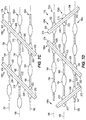
- FIGS. 7A-7D illustrate different embodiments of the flight bars 186 coupled to two or three chains 182.
- each end 202 of the flight bars 186a are fixed (e.g., removably fixed by fasteners) to a horizontal link 194 of one of the two chains 182a, 182b with an intermediate portion 206 of each flight bar 186a pivotally coupled to the ends 202 at movable or pivot joints 210.
- the intermediate portions 206 extend between the two chains 182a, 182b with the pivot joints 210 enabling the intermediate portion 206 to freely pivot relative to the ends 202.
- the illustrated flight bars 186a define a curved bar (e.g., two-bend bar, Z-shaped, etc.) having a central axis 214. Portions of the central axis 214 extending through the ends 202 of the flight bars 186a are substantially perpendicular to the longitudinal axes 190, and portions of the central axis 214 extending through the intermediate portion 206 of the flight bars 186a are substantially parallel to the longitudinal axes 190.
- a first portion of the central axis 214 that extends through the end 202 coupled to the first chain 182a is perpendicular to the longitudinal axes 190
- a second portion of the central axis 214 that extends through the end 202 coupled to the second chain 182b is perpendicular to the longitudinal axes 190
- the first portion of the central axis 214 is offset from the second portion of the central axis 214 in a direction parallel to the longitudinal axes 190.
- the flight bars 186a may be flexible members such that the pivot joints 210 may be flexible joints of the flight bars 186a.
- each end 202 of the flight bars 186b (similar to the flight bar 186a) are fixed to a horizontal link 194 of one of the two outer chains 182a, 182c.
- a central portion or fixed portion 218 of each flight bar 186b is fixed to a horizontal link 194 of the middle chain 182b.
- Each intermediate portion 206 of each flight bar 186b is pivotally coupled between one end 202 and the central portion 218 at two pivot joints 210 (e.g., each flight bar 186b includes four pivot joints 210).
- the central axis 214 of the flight bar 186b also defines a curved bar (e.g., four-bend bar, zig-zag shaped, etc.).
- Portions of the central axis 214 extending through the ends 202 and the central portion 218 are substantially perpendicular to the longitudinal axes 190, and portions of the central axis 214 extending through the intermediate portions 206 are substantially parallel to the longitudinal axes 190.
- the ends 202 and the central portions 218 of flight bars 186c are fixed to the horizontal links 194 by movable joints 222.
- the movable joints 222 allow movement (e.g., flexing) of the intermediate portions 206 relative to the central portion 218 as well as movement of the intermediate portions 206 relative to the ends 202.
- the central axis 214 of each flight bar 186c is linear and oriented at an oblique angle relative to the longitudinal axes 190.
- the central axes 214 of the flight bars 186c are oriented parallel to each other.
- each flight bar 186d is also linear and oriented at an oblique angle relative to the longitudinal axes 190, similar to the flight bars 186c. However, the central axes 214 of adjacent flight bars 186d are obliquely oriented.
- the longwall shearer 10 cuts material from the mine face 34, and the material is ultimately received within the upper channel 166 of the conveyor pan 150.
- the drive unit 102 of at least one end frame 98 rotates the plurality of sprockets 118 about the rotational axis 114 ( FIG. 4 ).
- each sprocket 118 engages one of the chains 182 and moves a portion of the chains 182 through the upper channel 166 in one direction (e.g., the first direction 38) and moves another portion of the chains 182 through the lower channel 158 in the other direction (e.g., the second direction 42).
- each chain 182 are received within the first link slot 134 of a respective sprocket 118
- the vertical links 198 of each chain 182 are received within the second link slot 138 of a respective sprocket 118 in order for the sprockets 118 to grip the chains 182 and move the chains 182 relative to the conveyor pan 150.
- each sprocket 118a-c will grip a respective chain 182a-c at a different point in time.
- the first sprocket 118a will grip a horizontal link 194 of the first chain 182a
- the second sprocket 118b will grip a horizontal link 194 of the second chain 182b
- the third sprocket 118c will grip a horizontal link 194 of the third chain 182c
- the illustrated flight bars 186 are able to pivot or flex about the joints 210, 222 in response to the sprockets 118a-c being angularly offset.
- the flight bars 186b pivot at the pivot joints 210.
- the first sprocket 118a begins to rotate the first chain 182a about the rotational axis 114 before the second chain 182b and the third chain 182c begin to rotate about the rotational axis 114.
- the end 202 of the flight bar 186b which is fixed to the first chain 182a, moves relative (e.g., moves vertically; FIG. 4 ) relative to the central portion 218 and the other end 202.
- the pivot joint 210 between the central portion 218 and the end 202 fixed to the first chain 182a enables movement between the end 202 and the central portion 218 as the flight bars 186b move around the rotational axis 114.
- Similar movement occurs between the central portion 218 and the end 202 fixed to the third chain 182c as the second sprocket 118b begins to rotate the second chain 182b before the third sprocket 118c begins to rotate the third chain 182c about the rotational axis 114.
- flight bars 186a illustrated in FIG. 7A as two sprockets 118 rotate the two chains 182a, 182b about the rotational axis 114.
- flight bars 186a, 186b begin to move around the rotational axis 114, the central axis 214 of each flight bar 186a, 186b bends about the central portion 218 ( FIG. 9 ).
- flight bars 186c, 186d illustrated in FIGS.
- the flight bars 186 will continue to pivot or flex around the rotational axis 114 until the flight bars 186 reach a half way position in their rotation about the rotational axis 114. Thereafter, the flight bars 186 will pivot or flex back into a generally planar flight bar configuration so that when the conveying element 178 disengages from the sprockets 118, the flight bars 186 move along the support plate 154 of the conveyor pan 150 ( FIG. 4 ). Consequently, the flight bars 186 can push the cut material that has been received within the upper channel 166 along the longitudinal axes 190 (e.g., the first direction 38) in order for the cut material to be transported relative to the mine face 34.
- the flight bars 186 can push the cut material that has been received within the upper channel 166 along the longitudinal axes 190 (e.g., the first direction 38) in order for the cut material to be transported relative to the mine face 34.
Landscapes
- Engineering & Computer Science (AREA)
- Mechanical Engineering (AREA)
- Mining & Mineral Resources (AREA)
- Life Sciences & Earth Sciences (AREA)
- General Life Sciences & Earth Sciences (AREA)
- Geochemistry & Mineralogy (AREA)
- Geology (AREA)
- Chain Conveyers (AREA)
- Attitude Control For Articles On Conveyors (AREA)
Claims (15)
- Förderanlage (46), die dazu konfiguriert ist, Material in Bezug zu einer Grubenabbaufront (34) zu bewegen, wobei die Förderanlage (46) aufweist:eine Förderwanne (150), die dazu konfiguriert ist, das Material zu stützen;eine Antriebseinheit (102), die eine Antriebswelle (110) und eine Vielzahl von Zahnrädern (118) aufweist, die an der Antriebswelle (100) befestigt sind, wobei die Antriebswelle (100) um eine Drehachse (114) getrieben wird; undein Förderelement (178), das eine Vielzahl von Ketten (182) und eine Vielzahl von Mitnehmern (186) aufweist, wobei jede der Ketten (182) von einem der Zahnräder (118) getrieben wird, um die Kette (182) und die Mitnehmer (186) über die Förderwanne (150) zu bewegen, wobei jeder der Mitnehmer (186) zwischen die Vielzahl von Ketten (182) geschaltet ist, wobei jeder der Vielzahl von Mitnehmern (186) einen ersten Abschnitt (202) und einen zweiten Abschnitt (206) aufweist, wobei der erste Abschnitt (202) durch ein bewegliches Gelenk (210, 222) mit dem zweiten Abschnitt (206) verbunden ist, wobei die Mitnehmer (186) dazu konfiguriert sind, das Material über die Förderwanne (150) zu bewegen, wobei die Vielzahl von Zahnrädern (118) um die Drehachse (114) herum zueinander winkelversetzt sind, und wobei sich der erste Abschnitt (202) bezüglich des zweiten Abschnitts (206) an dem beweglichen Gelenk (210, 222) im Ansprechen darauf bewegt, dass die Vielzahl von Ketten (182) in die Vielzahl von Zahnrädern (118) eingreifen und sich um die Drehachse (114) herum bewegen.
- Förderanlage (46) nach Anspruch 1, wobei jeder Mitnehmer (186) eine Mittelachse (214) aufweist, die sich zwischen einem ersten Ende und einem zweiten Ende jedes Mitnehmers (186) erstreckt, und wobei die Mittelachse (214) wenigstens einen gebogenen Abschnitt aufweist.
- Förderanlage (46) nach Anspruch 2, wobei jede Kette (182) eine Längsachse (190) definiert, und wobei wenigstens ein Abschnitt der Mittelachse (214) im Wesentlichen senkrecht zu der Längsachse (190) jeder Kette (182) ist, und wobei ein anderer Abschnitt der Mittelachse (214) im Wesentlichen parallel zu der Längsachse (190) jeder Kette (182) ist.
- Förderanlage (46) nach einem der vorhergehenden Ansprüche, wobei jede Kette (182) eine Vielzahl horizontaler Glieder (194) und eine Vielzahl vertikaler Glieder (198) aufweist, und wobei der erste Abschnitt (202) jedes Mitnehmers (186) fest mit einem der horizontalen Glieder (194) verbunden ist, und wobei der zweite Abschnitt (206) jedes Gewindegangs (186) ein Zwischenabschnitt ist, der sich zwischen zwei benachbarten Ketten (182) erstreckt.
- Förderanlage (46) nach Anspruch 4, wobei jeder Mitnehmer (186) zwei fixierte Abschnitte (202) aufweist, die jeweils fest mit einer der Ketten (182) verbunden sind, und wobei der Zwischenabschnitt (206) schwenkbar zwischen die zwei fixierten Abschnitte (202) geschaltet ist.
- Förderanlage (46) nach Anspruch 5, wobei die Vielzahl von Ketten (182) drei Ketten (182a, 182b, 182c) aufweist, und wobei jeder Mitnehmer (186) drei fixierte Abschnitte (202, 218) aufweist, wobei jeder der drei fixierten Abschnitte (202, 218) an einer der drei Ketten (182a, 182b, 182c) befestigt ist, und wobei jeder Mitnehmer (186) zwei Zwischenabschnitte (206) aufweist, wobei jeder der Zwischenabschnitte (206) schwenkbar zwischen zwei der drei fixierten Abschnitte (202, 218) geschaltet ist.
- Förderanlage (46) nach Anspruch 1, wobei die Vielzahl von Ketten (82) jeweils eine Längsachse (190) definieren,
wobei sich jeder der Vielzahl von Mitnehmern (186) entlang einer Mittelachse (214) erstreckt, die bezüglich der Längsachsen (190) schräg ausgerichtet ist, und wobei jeder Mitnehmer (186) einen dritten Abschnitt (202) aufweist, der von dem ersten Abschnitt (202) des Mitnehmers (186) in einer Richtung parallel zu den Längsachsen (190) versetzt ist. - Förderanlage (46) nach Anspruch 7, wobei sowohl der erste Abschnitt (202) als auch der dritte Abschnitt (202) im Wesentlichen senkrecht zu der Längsachse (190) jeder Kette (182) ausgerichtet sind.
- Förderanlage (46) nach Anspruch 7 oder 8, wobei jeder Mitnehmer (186) zwei gebogene Abschnitte aufweist.
- Förderanlage (46) nach Anspruch 9, wobei die beiden gebogenen Abschnitte zwischen den Ketten (182) angeordnet sind.
- Förderanlage (46) nach Anspruch 7 oder 8, wobei die Ketten (182) drei Ketten (182a, 182b, 182c) aufweisen, und wobei jeder Mitnehmer (186) vier gebogene Abschnitte aufweist.
- Förderanlage (46) nach Anspruch 11, wobei zwei der vier gebogenen Abschnitte zwischen der ersten Kette (182a) und der zweiten Kette (182b) angeordnet sind, und wobei die anderen zwei der vier gebogenen Abschnitte zwischen der zweiten Kette (182b) und der dritten Kette (182c) angeordnet sind.
- Förderanlage (46) nach den Ansprüchen 7-12, wobei ein Abschnitt der Mittelachse (214), der sich durch den zweiten Abschnitt (206) jedes Mitnehmers (186) erstreckt, im Wesentlichen parallel zu der Längsachse (190) jeder Kette (182) ist.
- Förderanlage (46) nach Anspruch 1 oder 4, wobei jeder Mitnehmer (186) eine Mittelachse (214) aufweist, die sich zwischen einem ersten Ende und einem zweiten Ende jedes Mitnehmers (186) erstreckt, und wobei die Mittelachse (214) linear ist.
- Förderanlage (46) nach Anspruch 7, wobei die Mittelachse (214) linear ist.
Priority Applications (2)
| Application Number | Priority Date | Filing Date | Title |
|---|---|---|---|
| PL18187049T PL3438409T3 (pl) | 2017-08-04 | 2018-08-02 | Przenośnik łańcuchowy i koło zębate napędowe do niego |
| EP20200777.9A EP3798411A1 (de) | 2017-08-04 | 2018-08-02 | Kettenförderer und antriebskettenrad dafür |
Applications Claiming Priority (1)
| Application Number | Priority Date | Filing Date | Title |
|---|---|---|---|
| US15/669,176 US10214360B1 (en) | 2017-08-04 | 2017-08-04 | Chain conveyor and drive sprocket for same |
Related Child Applications (2)
| Application Number | Title | Priority Date | Filing Date |
|---|---|---|---|
| EP20200777.9A Division-Into EP3798411A1 (de) | 2017-08-04 | 2018-08-02 | Kettenförderer und antriebskettenrad dafür |
| EP20200777.9A Division EP3798411A1 (de) | 2017-08-04 | 2018-08-02 | Kettenförderer und antriebskettenrad dafür |
Publications (3)
| Publication Number | Publication Date |
|---|---|
| EP3438409A2 EP3438409A2 (de) | 2019-02-06 |
| EP3438409A3 EP3438409A3 (de) | 2019-08-28 |
| EP3438409B1 true EP3438409B1 (de) | 2020-11-11 |
Family
ID=63143065
Family Applications (2)
| Application Number | Title | Priority Date | Filing Date |
|---|---|---|---|
| EP18187049.4A Not-in-force EP3438409B1 (de) | 2017-08-04 | 2018-08-02 | Kettenförderer und antriebskettenrad dafür |
| EP20200777.9A Withdrawn EP3798411A1 (de) | 2017-08-04 | 2018-08-02 | Kettenförderer und antriebskettenrad dafür |
Family Applications After (1)
| Application Number | Title | Priority Date | Filing Date |
|---|---|---|---|
| EP20200777.9A Withdrawn EP3798411A1 (de) | 2017-08-04 | 2018-08-02 | Kettenförderer und antriebskettenrad dafür |
Country Status (7)
| Country | Link |
|---|---|
| US (1) | US10214360B1 (de) |
| EP (2) | EP3438409B1 (de) |
| CN (2) | CN209241928U (de) |
| AU (1) | AU2018211240A1 (de) |
| PL (1) | PL3438409T3 (de) |
| RU (1) | RU2768427C2 (de) |
| ZA (1) | ZA201805228B (de) |
Families Citing this family (5)
| Publication number | Priority date | Publication date | Assignee | Title |
|---|---|---|---|---|
| US10214360B1 (en) * | 2017-08-04 | 2019-02-26 | Joy Global Underground Mining Llc | Chain conveyor and drive sprocket for same |
| CN111056227A (zh) * | 2020-01-09 | 2020-04-24 | 北京华海基业机械设备有限公司 | 一种矿用多股大规格重载刮板链输送机 |
| US11761333B2 (en) | 2020-11-16 | 2023-09-19 | Joy Global Underground Mining Llc | Cutting assembly for longwall mining system |
| US12006824B2 (en) | 2020-11-16 | 2024-06-11 | Joy Global Underground Mining Llc | Cutting assembly for longwall mining system |
| CN116374510A (zh) * | 2023-02-22 | 2023-07-04 | 中煤张家口煤矿机械有限责任公司 | 一种基于超大运量的三链传动系统及刮板输送机 |
Family Cites Families (28)
| Publication number | Priority date | Publication date | Assignee | Title |
|---|---|---|---|---|
| US1016190A (en) * | 1909-12-18 | 1912-01-30 | John F White | Flight conveyer. |
| US1753246A (en) * | 1927-01-19 | 1930-04-08 | Coloder Company | Loading machine |
| US1841925A (en) | 1927-03-14 | 1932-01-19 | Adin C Woodbury | Chain drive |
| US2002952A (en) * | 1933-07-26 | 1935-05-28 | Jeffrey Mfg Co | Material handling mechanism |
| GB454781A (en) * | 1935-08-10 | 1936-10-07 | Alfred Eickhoff | Improvements in endless conveyors of the scraper and trough type |
| US2590802A (en) * | 1947-05-23 | 1952-03-25 | Houilleres Bassin Du Nord | Pusher conveyer with sectional trough |
| US2717548A (en) | 1952-08-06 | 1955-09-13 | Food Machinery & Chemical Corp | Container traversing mechanism for food processing apparatus |
| GB1169940A (en) * | 1966-12-30 | 1969-11-05 | Parsons Chain Company Ltd | Continuous Chain Scraper Assemblies |
| US3610474A (en) * | 1969-10-06 | 1971-10-05 | Shunk Mfg Co Inc | Material conveyor and spreader |
| US4111296A (en) * | 1974-06-25 | 1978-09-05 | Glossop Mark B | Rock conveyors |
| US3927759A (en) * | 1974-07-15 | 1975-12-23 | Westinghouse Air Brake Co | Flight assembly for achieving balanced reaction forces in elevating-type scraper |
| GB1460376A (en) * | 1974-09-04 | 1977-01-06 | Reilloc Eng Ltd | Connector for conveyor chain assemblies |
| SU1377225A1 (ru) * | 1983-02-15 | 1988-02-28 | Донецкий научно-исследовательский институт | Т говый орган скребкового конвейера |
| US4685557A (en) | 1985-02-13 | 1987-08-11 | Ashworth Bros., Inc. | Conveyor belt drive sprocket system |
| FR2597841B1 (fr) * | 1986-04-28 | 1990-04-13 | Do Ugolny I | Organe de traction d'un convoyeur a raclettes |
| US5000310A (en) * | 1989-06-16 | 1991-03-19 | Joy Technologies Inc. | Chain and flight conveyor |
| FI90228C (fi) * | 1992-01-13 | 1994-01-10 | Kauko Rautio | Ketjukuljetin |
| US5427580A (en) | 1992-05-19 | 1995-06-27 | Borg-Warner Automotive, Inc. | Phased chain assemblies |
| DE10040186A1 (de) * | 2000-08-17 | 2002-03-14 | K B P Kettenwerk Becker Prunte | Mitnehmer für Kettenkratzförderer, insbesondere des Untertagebetriebes |
| US6719127B2 (en) | 2001-11-14 | 2004-04-13 | The Laitram Corporation | Compensation for shaft twist in the drive system of modular conveyor belts |
| US20050209033A1 (en) | 2004-03-19 | 2005-09-22 | Borgwarner Inc. | Spline phased multiple sprocket |
| WO2007092843A2 (en) | 2006-02-06 | 2007-08-16 | Thermodrive Llc | Direct drive conveyor belt system |
| WO2010123548A2 (en) | 2009-04-20 | 2010-10-28 | Cambridge International, Inc. | Compound sprocket for conveyor belt |
| WO2011041131A1 (en) * | 2009-09-30 | 2011-04-07 | Laitram, L.L.C. | Belt conveyor with a modular intermediate drive belt |
| CN201980687U (zh) * | 2011-01-30 | 2011-09-21 | 宝山钢铁股份有限公司 | 一种水平型埋刮板输送机刮板组件 |
| US8646595B2 (en) | 2011-05-23 | 2014-02-11 | Laitram, L.L.C. | Snap-on conveyor belt rollers |
| CN205471170U (zh) * | 2016-03-24 | 2016-08-17 | 湖北天宜机械股份有限公司 | 一种刮板输送机可调脱链器 |
| US10214360B1 (en) * | 2017-08-04 | 2019-02-26 | Joy Global Underground Mining Llc | Chain conveyor and drive sprocket for same |
-
2017
- 2017-08-04 US US15/669,176 patent/US10214360B1/en not_active Expired - Fee Related
-
2018
- 2018-08-01 AU AU2018211240A patent/AU2018211240A1/en not_active Abandoned
- 2018-08-02 EP EP18187049.4A patent/EP3438409B1/de not_active Not-in-force
- 2018-08-02 PL PL18187049T patent/PL3438409T3/pl unknown
- 2018-08-02 EP EP20200777.9A patent/EP3798411A1/de not_active Withdrawn
- 2018-08-03 CN CN201821246577.0U patent/CN209241928U/zh not_active Withdrawn - After Issue
- 2018-08-03 RU RU2018128402A patent/RU2768427C2/ru active
- 2018-08-03 CN CN201810877747.3A patent/CN109383987B/zh not_active Expired - Fee Related
- 2018-08-03 ZA ZA2018/05228A patent/ZA201805228B/en unknown
Non-Patent Citations (1)
| Title |
|---|
| None * |
Also Published As
| Publication number | Publication date |
|---|---|
| US20190039832A1 (en) | 2019-02-07 |
| RU2018128402A3 (de) | 2021-09-30 |
| US10214360B1 (en) | 2019-02-26 |
| PL3438409T3 (pl) | 2021-05-31 |
| RU2768427C2 (ru) | 2022-03-24 |
| CN109383987A (zh) | 2019-02-26 |
| EP3438409A2 (de) | 2019-02-06 |
| EP3438409A3 (de) | 2019-08-28 |
| RU2018128402A (ru) | 2020-02-05 |
| ZA201805228B (en) | 2019-04-24 |
| EP3798411A1 (de) | 2021-03-31 |
| AU2018211240A1 (en) | 2019-02-21 |
| CN209241928U (zh) | 2019-08-13 |
| CN109383987B (zh) | 2022-04-15 |
Similar Documents
| Publication | Publication Date | Title |
|---|---|---|
| EP3798411A1 (de) | Kettenförderer und antriebskettenrad dafür | |
| AU2023202741B2 (en) | Chain conveyor | |
| ZA200807558B (en) | A conveyor pan with improved edge shaping | |
| US4006937A (en) | Carriage especially for use in mines | |
| ZA201102465B (en) | A rack bar haulage system with an improved rackbar | |
| GB2094866A (en) | Haulage system for a mining machine | |
| US3367718A (en) | Mining conveyor arrangement with easily replaceable parts | |
| AU2011200247B2 (en) | A Rack Bar Haulage System with an Improved Rackbar to Line Pan Connection | |
| US3155225A (en) | Lateral plate pusher-type conveyor | |
| US3817579A (en) | Mining machine | |
| AU2022200412A1 (en) | Conveyor pan | |
| US2676005A (en) | Disintegrating and gathering chain | |
| CA1095542A (en) | Apparatus for cutting hard earth formations | |
| GB1585234A (en) | Conveyor for a mining machine | |
| AU2011200256A1 (en) | A Rack Bar Haulage System with an Improved Rackbar to Line Pan Connection | |
| US2341977A (en) | Loader | |
| US4281759A (en) | Conveyors | |
| US20070035173A1 (en) | Low Profile Mining Machine | |
| RU2794563C2 (ru) | Способ и устройство контроля степени износа у зубчатого барабана конвейера для горных разработок | |
| US3700285A (en) | Cutter chain support means | |
| SU857505A1 (ru) | Секци углового скребкового конвейера | |
| SU1355716A1 (ru) | Шит дл проходки тоннел | |
| AU8837698A (en) | Conveying apparatus for a longwall mining machine | |
| GB2170772A (en) | Angular mining conveyor | |
| GB1585867A (en) | Conveyors |
Legal Events
| Date | Code | Title | Description |
|---|---|---|---|
| PUAI | Public reference made under article 153(3) epc to a published international application that has entered the european phase |
Free format text: ORIGINAL CODE: 0009012 |
|
| STAA | Information on the status of an ep patent application or granted ep patent |
Free format text: STATUS: THE APPLICATION HAS BEEN PUBLISHED |
|
| AK | Designated contracting states |
Kind code of ref document: A2 Designated state(s): AL AT BE BG CH CY CZ DE DK EE ES FI FR GB GR HR HU IE IS IT LI LT LU LV MC MK MT NL NO PL PT RO RS SE SI SK SM TR |
|
| AX | Request for extension of the european patent |
Extension state: BA ME |
|
| RIC1 | Information provided on ipc code assigned before grant |
Ipc: E21F 13/00 20060101AFI20190408BHEP Ipc: B65G 23/44 20060101ALI20190408BHEP Ipc: E21F 13/06 20060101ALI20190408BHEP |
|
| PUAL | Search report despatched |
Free format text: ORIGINAL CODE: 0009013 |
|
| AK | Designated contracting states |
Kind code of ref document: A3 Designated state(s): AL AT BE BG CH CY CZ DE DK EE ES FI FR GB GR HR HU IE IS IT LI LT LU LV MC MK MT NL NO PL PT RO RS SE SI SK SM TR |
|
| AX | Request for extension of the european patent |
Extension state: BA ME |
|
| RIC1 | Information provided on ipc code assigned before grant |
Ipc: E21F 13/06 20060101ALI20190724BHEP Ipc: B65G 23/44 20060101ALI20190724BHEP Ipc: E21F 13/00 20060101AFI20190724BHEP |
|
| STAA | Information on the status of an ep patent application or granted ep patent |
Free format text: STATUS: REQUEST FOR EXAMINATION WAS MADE |
|
| 17P | Request for examination filed |
Effective date: 20200224 |
|
| RBV | Designated contracting states (corrected) |
Designated state(s): AL AT BE BG CH CY CZ DE DK EE ES FI FR GB GR HR HU IE IS IT LI LT LU LV MC MK MT NL NO PL PT RO RS SE SI SK SM TR |
|
| GRAP | Despatch of communication of intention to grant a patent |
Free format text: ORIGINAL CODE: EPIDOSNIGR1 |
|
| STAA | Information on the status of an ep patent application or granted ep patent |
Free format text: STATUS: GRANT OF PATENT IS INTENDED |
|
| INTG | Intention to grant announced |
Effective date: 20200529 |
|
| GRAS | Grant fee paid |
Free format text: ORIGINAL CODE: EPIDOSNIGR3 |
|
| GRAA | (expected) grant |
Free format text: ORIGINAL CODE: 0009210 |
|
| STAA | Information on the status of an ep patent application or granted ep patent |
Free format text: STATUS: THE PATENT HAS BEEN GRANTED |
|
| AK | Designated contracting states |
Kind code of ref document: B1 Designated state(s): AL AT BE BG CH CY CZ DE DK EE ES FI FR GB GR HR HU IE IS IT LI LT LU LV MC MK MT NL NO PL PT RO RS SE SI SK SM TR |
|
| REG | Reference to a national code |
Ref country code: GB Ref legal event code: FG4D |
|
| REG | Reference to a national code |
Ref country code: CH Ref legal event code: EP |
|
| REG | Reference to a national code |
Ref country code: AT Ref legal event code: REF Ref document number: 1333661 Country of ref document: AT Kind code of ref document: T Effective date: 20201115 |
|
| REG | Reference to a national code |
Ref country code: DE Ref legal event code: R096 Ref document number: 602018009566 Country of ref document: DE |
|
| REG | Reference to a national code |
Ref country code: IE Ref legal event code: FG4D |
|
| REG | Reference to a national code |
Ref country code: NL Ref legal event code: MP Effective date: 20201111 |
|
| REG | Reference to a national code |
Ref country code: AT Ref legal event code: MK05 Ref document number: 1333661 Country of ref document: AT Kind code of ref document: T Effective date: 20201111 |
|
| PG25 | Lapsed in a contracting state [announced via postgrant information from national office to epo] |
Ref country code: GR Free format text: LAPSE BECAUSE OF FAILURE TO SUBMIT A TRANSLATION OF THE DESCRIPTION OR TO PAY THE FEE WITHIN THE PRESCRIBED TIME-LIMIT Effective date: 20210212 Ref country code: NO Free format text: LAPSE BECAUSE OF FAILURE TO SUBMIT A TRANSLATION OF THE DESCRIPTION OR TO PAY THE FEE WITHIN THE PRESCRIBED TIME-LIMIT Effective date: 20210211 Ref country code: FI Free format text: LAPSE BECAUSE OF FAILURE TO SUBMIT A TRANSLATION OF THE DESCRIPTION OR TO PAY THE FEE WITHIN THE PRESCRIBED TIME-LIMIT Effective date: 20201111 Ref country code: RS Free format text: LAPSE BECAUSE OF FAILURE TO SUBMIT A TRANSLATION OF THE DESCRIPTION OR TO PAY THE FEE WITHIN THE PRESCRIBED TIME-LIMIT Effective date: 20201111 Ref country code: PT Free format text: LAPSE BECAUSE OF FAILURE TO SUBMIT A TRANSLATION OF THE DESCRIPTION OR TO PAY THE FEE WITHIN THE PRESCRIBED TIME-LIMIT Effective date: 20210311 |
|
| PG25 | Lapsed in a contracting state [announced via postgrant information from national office to epo] |
Ref country code: BG Free format text: LAPSE BECAUSE OF FAILURE TO SUBMIT A TRANSLATION OF THE DESCRIPTION OR TO PAY THE FEE WITHIN THE PRESCRIBED TIME-LIMIT Effective date: 20210211 Ref country code: SE Free format text: LAPSE BECAUSE OF FAILURE TO SUBMIT A TRANSLATION OF THE DESCRIPTION OR TO PAY THE FEE WITHIN THE PRESCRIBED TIME-LIMIT Effective date: 20201111 Ref country code: IS Free format text: LAPSE BECAUSE OF FAILURE TO SUBMIT A TRANSLATION OF THE DESCRIPTION OR TO PAY THE FEE WITHIN THE PRESCRIBED TIME-LIMIT Effective date: 20210311 Ref country code: LV Free format text: LAPSE BECAUSE OF FAILURE TO SUBMIT A TRANSLATION OF THE DESCRIPTION OR TO PAY THE FEE WITHIN THE PRESCRIBED TIME-LIMIT Effective date: 20201111 Ref country code: AT Free format text: LAPSE BECAUSE OF FAILURE TO SUBMIT A TRANSLATION OF THE DESCRIPTION OR TO PAY THE FEE WITHIN THE PRESCRIBED TIME-LIMIT Effective date: 20201111 |
|
| REG | Reference to a national code |
Ref country code: LT Ref legal event code: MG9D |
|
| PG25 | Lapsed in a contracting state [announced via postgrant information from national office to epo] |
Ref country code: HR Free format text: LAPSE BECAUSE OF FAILURE TO SUBMIT A TRANSLATION OF THE DESCRIPTION OR TO PAY THE FEE WITHIN THE PRESCRIBED TIME-LIMIT Effective date: 20201111 |
|
| PG25 | Lapsed in a contracting state [announced via postgrant information from national office to epo] |
Ref country code: LT Free format text: LAPSE BECAUSE OF FAILURE TO SUBMIT A TRANSLATION OF THE DESCRIPTION OR TO PAY THE FEE WITHIN THE PRESCRIBED TIME-LIMIT Effective date: 20201111 Ref country code: SK Free format text: LAPSE BECAUSE OF FAILURE TO SUBMIT A TRANSLATION OF THE DESCRIPTION OR TO PAY THE FEE WITHIN THE PRESCRIBED TIME-LIMIT Effective date: 20201111 Ref country code: RO Free format text: LAPSE BECAUSE OF FAILURE TO SUBMIT A TRANSLATION OF THE DESCRIPTION OR TO PAY THE FEE WITHIN THE PRESCRIBED TIME-LIMIT Effective date: 20201111 Ref country code: CZ Free format text: LAPSE BECAUSE OF FAILURE TO SUBMIT A TRANSLATION OF THE DESCRIPTION OR TO PAY THE FEE WITHIN THE PRESCRIBED TIME-LIMIT Effective date: 20201111 Ref country code: EE Free format text: LAPSE BECAUSE OF FAILURE TO SUBMIT A TRANSLATION OF THE DESCRIPTION OR TO PAY THE FEE WITHIN THE PRESCRIBED TIME-LIMIT Effective date: 20201111 Ref country code: SM Free format text: LAPSE BECAUSE OF FAILURE TO SUBMIT A TRANSLATION OF THE DESCRIPTION OR TO PAY THE FEE WITHIN THE PRESCRIBED TIME-LIMIT Effective date: 20201111 |
|
| REG | Reference to a national code |
Ref country code: DE Ref legal event code: R097 Ref document number: 602018009566 Country of ref document: DE |
|
| PG25 | Lapsed in a contracting state [announced via postgrant information from national office to epo] |
Ref country code: DK Free format text: LAPSE BECAUSE OF FAILURE TO SUBMIT A TRANSLATION OF THE DESCRIPTION OR TO PAY THE FEE WITHIN THE PRESCRIBED TIME-LIMIT Effective date: 20201111 |
|
| PLBE | No opposition filed within time limit |
Free format text: ORIGINAL CODE: 0009261 |
|
| STAA | Information on the status of an ep patent application or granted ep patent |
Free format text: STATUS: NO OPPOSITION FILED WITHIN TIME LIMIT |
|
| 26N | No opposition filed |
Effective date: 20210812 |
|
| PG25 | Lapsed in a contracting state [announced via postgrant information from national office to epo] |
Ref country code: NL Free format text: LAPSE BECAUSE OF FAILURE TO SUBMIT A TRANSLATION OF THE DESCRIPTION OR TO PAY THE FEE WITHIN THE PRESCRIBED TIME-LIMIT Effective date: 20201111 Ref country code: AL Free format text: LAPSE BECAUSE OF FAILURE TO SUBMIT A TRANSLATION OF THE DESCRIPTION OR TO PAY THE FEE WITHIN THE PRESCRIBED TIME-LIMIT Effective date: 20201111 Ref country code: IT Free format text: LAPSE BECAUSE OF FAILURE TO SUBMIT A TRANSLATION OF THE DESCRIPTION OR TO PAY THE FEE WITHIN THE PRESCRIBED TIME-LIMIT Effective date: 20201111 |
|
| PG25 | Lapsed in a contracting state [announced via postgrant information from national office to epo] |
Ref country code: SI Free format text: LAPSE BECAUSE OF FAILURE TO SUBMIT A TRANSLATION OF THE DESCRIPTION OR TO PAY THE FEE WITHIN THE PRESCRIBED TIME-LIMIT Effective date: 20201111 |
|
| PGFP | Annual fee paid to national office [announced via postgrant information from national office to epo] |
Ref country code: DE Payment date: 20210827 Year of fee payment: 4 Ref country code: PL Payment date: 20210721 Year of fee payment: 4 |
|
| PG25 | Lapsed in a contracting state [announced via postgrant information from national office to epo] |
Ref country code: ES Free format text: LAPSE BECAUSE OF FAILURE TO SUBMIT A TRANSLATION OF THE DESCRIPTION OR TO PAY THE FEE WITHIN THE PRESCRIBED TIME-LIMIT Effective date: 20201111 |
|
| REG | Reference to a national code |
Ref country code: CH Ref legal event code: PL |
|
| PG25 | Lapsed in a contracting state [announced via postgrant information from national office to epo] |
Ref country code: MC Free format text: LAPSE BECAUSE OF FAILURE TO SUBMIT A TRANSLATION OF THE DESCRIPTION OR TO PAY THE FEE WITHIN THE PRESCRIBED TIME-LIMIT Effective date: 20201111 |
|
| REG | Reference to a national code |
Ref country code: BE Ref legal event code: MM Effective date: 20210831 |
|
| PG25 | Lapsed in a contracting state [announced via postgrant information from national office to epo] |
Ref country code: LI Free format text: LAPSE BECAUSE OF NON-PAYMENT OF DUE FEES Effective date: 20210831 Ref country code: CH Free format text: LAPSE BECAUSE OF NON-PAYMENT OF DUE FEES Effective date: 20210831 |
|
| PG25 | Lapsed in a contracting state [announced via postgrant information from national office to epo] |
Ref country code: IS Free format text: LAPSE BECAUSE OF FAILURE TO SUBMIT A TRANSLATION OF THE DESCRIPTION OR TO PAY THE FEE WITHIN THE PRESCRIBED TIME-LIMIT Effective date: 20210311 Ref country code: LU Free format text: LAPSE BECAUSE OF NON-PAYMENT OF DUE FEES Effective date: 20210802 |
|
| PG25 | Lapsed in a contracting state [announced via postgrant information from national office to epo] |
Ref country code: FR Free format text: LAPSE BECAUSE OF NON-PAYMENT OF DUE FEES Effective date: 20210831 Ref country code: BE Free format text: LAPSE BECAUSE OF NON-PAYMENT OF DUE FEES Effective date: 20210831 Ref country code: IE Free format text: LAPSE BECAUSE OF NON-PAYMENT OF DUE FEES Effective date: 20210802 |
|
| REG | Reference to a national code |
Ref country code: DE Ref legal event code: R119 Ref document number: 602018009566 Country of ref document: DE |
|
| GBPC | Gb: european patent ceased through non-payment of renewal fee |
Effective date: 20220802 |
|
| PG25 | Lapsed in a contracting state [announced via postgrant information from national office to epo] |
Ref country code: CY Free format text: LAPSE BECAUSE OF FAILURE TO SUBMIT A TRANSLATION OF THE DESCRIPTION OR TO PAY THE FEE WITHIN THE PRESCRIBED TIME-LIMIT Effective date: 20201111 |
|
| PG25 | Lapsed in a contracting state [announced via postgrant information from national office to epo] |
Ref country code: HU Free format text: LAPSE BECAUSE OF FAILURE TO SUBMIT A TRANSLATION OF THE DESCRIPTION OR TO PAY THE FEE WITHIN THE PRESCRIBED TIME-LIMIT; INVALID AB INITIO Effective date: 20180802 Ref country code: DE Free format text: LAPSE BECAUSE OF NON-PAYMENT OF DUE FEES Effective date: 20230301 |
|
| PG25 | Lapsed in a contracting state [announced via postgrant information from national office to epo] |
Ref country code: GB Free format text: LAPSE BECAUSE OF NON-PAYMENT OF DUE FEES Effective date: 20220802 |
|
| PG25 | Lapsed in a contracting state [announced via postgrant information from national office to epo] |
Ref country code: MK Free format text: LAPSE BECAUSE OF FAILURE TO SUBMIT A TRANSLATION OF THE DESCRIPTION OR TO PAY THE FEE WITHIN THE PRESCRIBED TIME-LIMIT Effective date: 20201111 |
|
| PG25 | Lapsed in a contracting state [announced via postgrant information from national office to epo] |
Ref country code: PL Free format text: LAPSE BECAUSE OF NON-PAYMENT OF DUE FEES Effective date: 20220802 |
|
| PG25 | Lapsed in a contracting state [announced via postgrant information from national office to epo] |
Ref country code: TR Free format text: LAPSE BECAUSE OF FAILURE TO SUBMIT A TRANSLATION OF THE DESCRIPTION OR TO PAY THE FEE WITHIN THE PRESCRIBED TIME-LIMIT Effective date: 20201111 |
|
| PG25 | Lapsed in a contracting state [announced via postgrant information from national office to epo] |
Ref country code: MT Free format text: LAPSE BECAUSE OF FAILURE TO SUBMIT A TRANSLATION OF THE DESCRIPTION OR TO PAY THE FEE WITHIN THE PRESCRIBED TIME-LIMIT Effective date: 20201111 |