EP3437819B1 - Foamed composite molding and method for manufacturing foamed composite molding - Google Patents
Foamed composite molding and method for manufacturing foamed composite molding Download PDFInfo
- Publication number
- EP3437819B1 EP3437819B1 EP17773895.2A EP17773895A EP3437819B1 EP 3437819 B1 EP3437819 B1 EP 3437819B1 EP 17773895 A EP17773895 A EP 17773895A EP 3437819 B1 EP3437819 B1 EP 3437819B1
- Authority
- EP
- European Patent Office
- Prior art keywords
- molded product
- insert material
- foamed molded
- mold foamed
- polyurethane foam
- Prior art date
- Legal status (The legal status is an assumption and is not a legal conclusion. Google has not performed a legal analysis and makes no representation as to the accuracy of the status listed.)
- Active
Links
Images



Classifications
-
- A—HUMAN NECESSITIES
- A47—FURNITURE; DOMESTIC ARTICLES OR APPLIANCES; COFFEE MILLS; SPICE MILLS; SUCTION CLEANERS IN GENERAL
- A47C—CHAIRS; SOFAS; BEDS
- A47C27/00—Spring, stuffed or fluid mattresses or cushions specially adapted for chairs, beds or sofas
- A47C27/14—Spring, stuffed or fluid mattresses or cushions specially adapted for chairs, beds or sofas with foamed material inlays
-
- B—PERFORMING OPERATIONS; TRANSPORTING
- B29—WORKING OF PLASTICS; WORKING OF SUBSTANCES IN A PLASTIC STATE IN GENERAL
- B29C—SHAPING OR JOINING OF PLASTICS; SHAPING OF MATERIAL IN A PLASTIC STATE, NOT OTHERWISE PROVIDED FOR; AFTER-TREATMENT OF THE SHAPED PRODUCTS, e.g. REPAIRING
- B29C39/00—Shaping by casting, i.e. introducing the moulding material into a mould or between confining surfaces without significant moulding pressure; Apparatus therefor
- B29C39/02—Shaping by casting, i.e. introducing the moulding material into a mould or between confining surfaces without significant moulding pressure; Apparatus therefor for making articles of definite length, i.e. discrete articles
- B29C39/10—Shaping by casting, i.e. introducing the moulding material into a mould or between confining surfaces without significant moulding pressure; Apparatus therefor for making articles of definite length, i.e. discrete articles incorporating preformed parts or layers, e.g. casting around inserts or for coating articles
-
- B—PERFORMING OPERATIONS; TRANSPORTING
- B29—WORKING OF PLASTICS; WORKING OF SUBSTANCES IN A PLASTIC STATE IN GENERAL
- B29C—SHAPING OR JOINING OF PLASTICS; SHAPING OF MATERIAL IN A PLASTIC STATE, NOT OTHERWISE PROVIDED FOR; AFTER-TREATMENT OF THE SHAPED PRODUCTS, e.g. REPAIRING
- B29C44/00—Shaping by internal pressure generated in the material, e.g. swelling or foaming ; Producing porous or cellular expanded plastics articles
-
- B—PERFORMING OPERATIONS; TRANSPORTING
- B29—WORKING OF PLASTICS; WORKING OF SUBSTANCES IN A PLASTIC STATE IN GENERAL
- B29C—SHAPING OR JOINING OF PLASTICS; SHAPING OF MATERIAL IN A PLASTIC STATE, NOT OTHERWISE PROVIDED FOR; AFTER-TREATMENT OF THE SHAPED PRODUCTS, e.g. REPAIRING
- B29C44/00—Shaping by internal pressure generated in the material, e.g. swelling or foaming ; Producing porous or cellular expanded plastics articles
- B29C44/02—Shaping by internal pressure generated in the material, e.g. swelling or foaming ; Producing porous or cellular expanded plastics articles for articles of definite length, i.e. discrete articles
- B29C44/12—Incorporating or moulding on preformed parts, e.g. inserts or reinforcements
- B29C44/1271—Incorporating or moulding on preformed parts, e.g. inserts or reinforcements the preformed parts being partially covered
-
- B—PERFORMING OPERATIONS; TRANSPORTING
- B60—VEHICLES IN GENERAL
- B60N—SEATS SPECIALLY ADAPTED FOR VEHICLES; VEHICLE PASSENGER ACCOMMODATION NOT OTHERWISE PROVIDED FOR
- B60N2/00—Seats specially adapted for vehicles; Arrangement or mounting of seats in vehicles
- B60N2/70—Upholstery springs ; Upholstery
- B60N2/7017—Upholstery springs ; Upholstery characterised by the manufacturing process; manufacturing upholstery or upholstery springs not otherwise provided for
-
- B—PERFORMING OPERATIONS; TRANSPORTING
- B29—WORKING OF PLASTICS; WORKING OF SUBSTANCES IN A PLASTIC STATE IN GENERAL
- B29K—INDEXING SCHEME ASSOCIATED WITH SUBCLASSES B29B, B29C OR B29D, RELATING TO MOULDING MATERIALS OR TO MATERIALS FOR MOULDS, REINFORCEMENTS, FILLERS OR PREFORMED PARTS, e.g. INSERTS
- B29K2075/00—Use of PU, i.e. polyureas or polyurethanes or derivatives thereof, as moulding material
-
- B—PERFORMING OPERATIONS; TRANSPORTING
- B29—WORKING OF PLASTICS; WORKING OF SUBSTANCES IN A PLASTIC STATE IN GENERAL
- B29K—INDEXING SCHEME ASSOCIATED WITH SUBCLASSES B29B, B29C OR B29D, RELATING TO MOULDING MATERIALS OR TO MATERIALS FOR MOULDS, REINFORCEMENTS, FILLERS OR PREFORMED PARTS, e.g. INSERTS
- B29K2105/00—Condition, form or state of moulded material or of the material to be shaped
- B29K2105/04—Condition, form or state of moulded material or of the material to be shaped cellular or porous
-
- B—PERFORMING OPERATIONS; TRANSPORTING
- B29—WORKING OF PLASTICS; WORKING OF SUBSTANCES IN A PLASTIC STATE IN GENERAL
- B29K—INDEXING SCHEME ASSOCIATED WITH SUBCLASSES B29B, B29C OR B29D, RELATING TO MOULDING MATERIALS OR TO MATERIALS FOR MOULDS, REINFORCEMENTS, FILLERS OR PREFORMED PARTS, e.g. INSERTS
- B29K2705/00—Use of metals, their alloys or their compounds, for preformed parts, e.g. for inserts
-
- B—PERFORMING OPERATIONS; TRANSPORTING
- B29—WORKING OF PLASTICS; WORKING OF SUBSTANCES IN A PLASTIC STATE IN GENERAL
- B29L—INDEXING SCHEME ASSOCIATED WITH SUBCLASS B29C, RELATING TO PARTICULAR ARTICLES
- B29L2031/00—Other particular articles
- B29L2031/30—Vehicles, e.g. ships or aircraft, or body parts thereof
- B29L2031/3005—Body finishings
-
- B—PERFORMING OPERATIONS; TRANSPORTING
- B29—WORKING OF PLASTICS; WORKING OF SUBSTANCES IN A PLASTIC STATE IN GENERAL
- B29L—INDEXING SCHEME ASSOCIATED WITH SUBCLASS B29C, RELATING TO PARTICULAR ARTICLES
- B29L2031/00—Other particular articles
- B29L2031/58—Upholstery or cushions, e.g. vehicle upholstery or interior padding
-
- B—PERFORMING OPERATIONS; TRANSPORTING
- B29—WORKING OF PLASTICS; WORKING OF SUBSTANCES IN A PLASTIC STATE IN GENERAL
- B29L—INDEXING SCHEME ASSOCIATED WITH SUBCLASS B29C, RELATING TO PARTICULAR ARTICLES
- B29L2031/00—Other particular articles
- B29L2031/771—Seats
-
- Y—GENERAL TAGGING OF NEW TECHNOLOGICAL DEVELOPMENTS; GENERAL TAGGING OF CROSS-SECTIONAL TECHNOLOGIES SPANNING OVER SEVERAL SECTIONS OF THE IPC; TECHNICAL SUBJECTS COVERED BY FORMER USPC CROSS-REFERENCE ART COLLECTIONS [XRACs] AND DIGESTS
- Y10—TECHNICAL SUBJECTS COVERED BY FORMER USPC
- Y10T—TECHNICAL SUBJECTS COVERED BY FORMER US CLASSIFICATION
- Y10T428/00—Stock material or miscellaneous articles
- Y10T428/24—Structurally defined web or sheet [e.g., overall dimension, etc.]
- Y10T428/24273—Structurally defined web or sheet [e.g., overall dimension, etc.] including aperture
-
- Y—GENERAL TAGGING OF NEW TECHNOLOGICAL DEVELOPMENTS; GENERAL TAGGING OF CROSS-SECTIONAL TECHNOLOGIES SPANNING OVER SEVERAL SECTIONS OF THE IPC; TECHNICAL SUBJECTS COVERED BY FORMER USPC CROSS-REFERENCE ART COLLECTIONS [XRACs] AND DIGESTS
- Y10—TECHNICAL SUBJECTS COVERED BY FORMER USPC
- Y10T—TECHNICAL SUBJECTS COVERED BY FORMER US CLASSIFICATION
- Y10T428/00—Stock material or miscellaneous articles
- Y10T428/24—Structurally defined web or sheet [e.g., overall dimension, etc.]
- Y10T428/24273—Structurally defined web or sheet [e.g., overall dimension, etc.] including aperture
- Y10T428/24322—Composite web or sheet
- Y10T428/24331—Composite web or sheet including nonapertured component
Definitions
- the present invention relates to a foamed composite molded product and a method of producing the foamed composite molded product.
- a vehicle seat has typically been produced by providing a seat body made of polyurethane foam in an integrated manner with a metal wire embedded therein.
- the metal wire serves as an insert material for stabilizing the shape of the vehicle seat.
- polyurethane foam is combined with an in-mold foamed molded product unit, which is molded from thermoplastic resin.
- the in-mold foamed molded product unit is obtained by insert molding in which an insert material (for example, a metal wire) is provided in an in-mold foamed molded product, made of thermoplastic resin expanded particles.
- the in-mold foamed molded product unit is used as a core material of the vehicle seat.
- the vehicle seat is obtained by providing the in-mold foamed molded product unit integrally with the polyurethane foam and then covering the in-mold foamed molded product unit and the polyurethane foam with a seat cover.
- Patent Literature 1 a surface of a molded product (in-mold foamed molded product) made of thermoplastic resin includes a contact region at which the molded product comes into contact with a different-material layer (polyurethane foam).
- the contact region is heated to a temperature which is not less than 80% of a softening temperature of the molded product. This heating causes expandable resin particles in the region of contact to soften and expand so as to form unevenness in the region of contact.
- the different-material layer is provided so as to enter depressions in the unevenness.
- Patent Literature 2 discloses carrying out an adhesiveness-providing treatment, such as a corona discharge treatment or coating with an anchor coat agent, between padding (polyurethane foam) and a foamed molded product (in-mold foamed molded product) made of olefin resin. This increases the adhesion strength between the surface of the foamed molded product and the surface of the padding.
- an adhesiveness-providing treatment such as a corona discharge treatment or coating with an anchor coat agent
- Patent Literature 3 discloses a configuration in which an opening is provided to a base material layer (in-mold foamed molded product) made of olefin resin. Polyurethane foam enters into the opening in the base material layer. This causes the base material layer and the polyurethane foam to be in close contact over a large area and in a complex manner. As such, the base material layer and the polyurethane foam are unified in a laminar manner with a high bonding strength.
- Patent Literature 4 discloses a configuration in which an outer envelope foam (polyurethane foam) is adhered to a reinforcement foam (in-mold foamed molded product) along the entire surface of the reinforcement foam.
- US2011221254A1 discloses preambles of claims 1 and 12.
- Patent Literatures 1 to 3 each include a means of improving the adhesion strength between (i) an in-mold foamed molded product made of thermoplastic resin and (ii) polyurethane foam.
- thermoplastic resin by its nature has poor adhesion with polyurethane foam. As such, even though the adhesion strength between the in-mold foamed molded product and the polyurethane foam is improved, the adhesion strength is still insufficient.
- An object of the present invention lies in providing (i) a foamed composite molded product in which polyurethane foam is unlikely to become separated from an in-mold foamed molded product unit, the in-mold foamed molded product unit including an in-mold foamed molded product and an insert material which are integrally molded, and (ii) a method of producing the foamed composite molded product.
- the insert material molded integrally with the in-mold foamed molded product is exposed. This makes it possible for the exposed part of the insert material to adhere to the polyurethane foam. It is also possible for the polyurethane foam to envelop the exposed part of the insert material.
- used as a material of the insert material is a material which has better adhesion with the polyurethane foam than does the in-mold foamed molded product.
- the in-mold foamed molded product unit including an in-mold foamed molded product and an insert material which are integrally molded.
- the insert material preferably has a higher strength than the in-mold foamed molded product.
- a method of producing a foamed composite molded product in accordance with an embodiment of the present invention is defined in claim 12.
- the method makes it possible to provide a foamed composite molded product in which polyurethane foam is unlikely to become separated from an in-mold foamed molded product unit.
- the present invention brings about an effect of making polyurethane foam unlikely to become separated from an in-mold foamed molded product unit, the in-mold foamed molded product unit including an in-mold foamed molded product and an insert material which are integrally molded.
- An object of the present invention is to make polyurethane foam less likely to become separated from an in-mold foamed molded product unit.
- adhesion is poor between polyurethane foam and an in-mold foamed molded product made of olefin resin or the like.
- polyurethane foam is typically formed on a surface of only a part of the in-mold foamed molded product. As such, it is unfeasible to prevent separation of the polyurethane foam from the in-mold foamed molded product by forming the polyurethane foam in a manner so as to envelop the in-mold foamed molded product.
- Fig. 1 is an external lateral view illustrating a foamed composite molded product.
- a foamed composite molded product 1 includes polyurethane foam 2 and an in-mold foamed molded product unit 5 which have been molded integrally with each other.
- the in-mold foamed molded product unit 5 includes an insert material 3 and an in-mold foamed molded product constituted by thermoplastic resin expanded particles.
- an in-mold foamed molded product 4, constituted by polyolefin-based resin expanded particles, is molded integrally with the insert material 3.
- the foamed composite molded product 1 can be produced by forming the polyurethane foam 2 so as to be in contact with a portion of the insert material 3, which portion is exposed to the outside of the in-mold foamed molded product 4. This is illustrated in more detail in Fig. 2 onward.
- the in-mold foamed molded product is preferably made of polyolefin resin.
- the polyurethane foam 2 is preferably (i) formed on at least a surface of the in-mold foamed molded product 4 which surface is on a side away from a vehicle-mounting side of the in-mold foamed molded product 4 but (ii) not formed on a surface on the vehicle-mounting side. That is, as illustrated in Fig. 1 , the polyurethane foam 2 may be formed so as to cover only a portion of the in-mold foamed molded product 4. In other words, as illustrated in Fig.
- the polyurethane foam 2 may be formed in a manner so as to be formed on a first surface 41 of the in-mold foamed molded product 4 but not to a second surface 42 of the in-mold foamed molded product 4, which second surface 42 is on a reverse side with respect to the first surface 41.
- the insert material 3 is provided inside the in-mold foamed molded product 4.
- the insert material 3 may be made of any of a variety of materials, provided that the insert material 3 is stronger against breakage (i.e., has a higher tensile strength) than the in-mold foamed molded product 4.
- the insert material 3 may be made of any of a variety of materials provided that the insert material 3 is harder than the in-mold foamed molded product 4, or, if the material of the insert material 3 is softer than the in-mold foamed molded product 4, provided that the insert material 3 is less easily broken than the in-mold foamed molded product 4.
- the insert material 3 is preferably made of a material having high affinity with the polyurethane foam 2.
- Possible examples of materials for the insert material 3 include metal, inorganic fiber (carbon fiber, glass fiber, and the like), fiber reinforced plastic (carbon fiber reinforced plastic, glass fiber reinforced plastic, and the like), fiber reinforced metal, wood, and concrete. Out of these examples, metal wire is preferable as the material of the insert material 3. Examples of metals which can be used for the insert material 3 include iron, stainless steel, zinc, and aluminum.
- a base material resin used for the thermoplastic resin expanded particles is not particularly limited. Possible examples include polyolefin resin, polystyrene resin, styrene-modified polyolefin resin (olefin-modified polystyrene resin), and polyester resin. Out of these examples, the use of an olefin resin such as polyolefin resin or styrene-modified polyolefin resin, and more preferably the use of polyolefin resin, provides a superior shock-absorbing property, chemical resistance, heat resistance, and strain recovery rate after compression, and allows for easy recycling.
- the polyolefin resin is not particularly limited. Possible examples include polypropylene resin and polyethylene resin. Examples of the polypropylene resin include a propylene homopolymer, an ethylene/propylene copolymer, and an ethylene/propylene/1-butene copolymer. Examples of the polyethylene resin include an ethylene homopolymer, high density polyethylene resin, medium density polyethylene resin, low density polyethylene resin, and linear low-density polyethylene resin. Specific examples include an ethylene/1-butene copolymer and an ethylene/4-methyl-1-pentene copolymer.
- the ethylene/propylene copolymer, the ethylene/propylene/1-butene copolymer, the ethylene/1-butene copolymer, and the ethylene/4-methyl-1-pentene copolymer can each be a random copolymer or a block copolymer.
- a method of producing the expanded particle is not particularly limited.
- a conventionally known production method can be employed.
- possible examples of the production method include the methods disclosed in International Patent Application Publication No. WO 2009/075208 , Japanese Patent Application Publication, Tokukai, No. 2006-117842 , and the like.
- possible examples of the production method include the methods disclosed in Japanese Patent Application Publication, Tokukai, No. 2003-201360 , Japanese Patent Application Publication, Tokukai, No. 2014-118474 , International Patent Application Publication No. WO 2015/137363 , and the like.
- styrene-modified polyolefin-based resin expanded particles possible examples include the methods disclosed in Japanese Patent Application Publication, Tokukai, No. 2008-239794 , International Patent Application Publication No. WO2016/152243 , and the like. Note that the method of producing the expanded particles is not limited to the above methods.
- Expanded particles obtained via the above methods can be made to include or be coated with an additive as necessary by use of a conventionally known method.
- an additive include a flame retarder, an anti-static agent, and a colorant.
- Particle size of the expanded particles is not particularly limited and can be, for example, 1 mm to 10 mm. In terms of a mold-filling property, the particle size is preferably 1 mm to 5 mm and more preferably 1 mm to 3 mm.
- the expansion ratio of the expanded particles is not particularly limited and can be, for example, 3 times to 90 times. In terms of mechanical strength and moldability, the expansion ratio is preferably 5 times to 60 times and more preferably 5 times to 45 times.
- Expanded particles as described above are commercially available as, for example, EPERAN-PP and EPERAN-XL (manufactured by Kaneka Corporation), and are easily acquired.
- the in-mold foamed molded product 4 is hereinafter described as being an in-mold foamed molded product made of polyolefin-based resin expanded particles.
- the in-mold foamed molded product 4 is molded, with use of a mold apparatus for in-mold foam molding, by heating polyolefin-based resin expanded particles so as to expand the particles and cause them to be fused to each other.
- a detailed description is as follows.
- the mold apparatus for in-mold foam molding includes (i) a concave mold unit having a concave mold and a concave mold housing which holds the concave mold and (ii) a convex mold unit having a convex mold and a convex mold housing which holds the convex mold.
- the concave mold and the convex mold form a space when closed together.
- Polyolefin-based resin expanded particles are filled into this space.
- the expanded particles may have an inorganic gas or the like impregnated therein beforehand so as to increase internal pressure, or may be expanded particles which are at atmospheric pressure and not internally pressurized.
- saturated steam pressure of approximately 0.04 MPa(G) to 0.40 MPa(G) is supplied to chambers respectively provided to the concave mold housing and the convex mold housing. This heats the polyolefin-based resin expanded particles so as to expand the particles and cause them to be fused to each other. In this way, the in-mold foamed molded product 4 is obtained by in-mold foam molding of the polyolefin-based resin expanded particles.
- the in-mold foamed molded product unit 5 is obtained by providing the insert material 3 to the convex mold or the concave mold of the mold apparatus for the in-mold foamed molded product and carrying out the above technique for producing the in-mold foamed molded product, such that the in-mold foamed molded product 4 is molded integrally with the insert material 3.
- the in-mold foamed molded product unit 5 can be used as, for example, a core material for a vehicle seat.
- a vehicle seat can be obtained by molding the in-mold foamed molded product unit 5 and the polyurethane foam 2 integrally and then covering the in-mold foamed molded product unit 5 and the polyurethane foam 2 with a seat cover.
- prepared firstly is a unit in which the in-mold foamed molded product 4 is molded integrally with the insert material 3 such that the insert material 3 is inside the in-mold foamed molded product 4. A portion of the insert material 3 is exposed to the outside of the in-mold foamed molded product 4 (step of preparing in-mold foamed molded product unit).
- the portion of the insert material 3 which is exposed to the outside of the in-mold foamed molded product 4 comes into contact with the polyurethane foam 2 (step of providing the polyurethane foam such that the polyurethane foam is in contact with the portion exposed to the outside of the in-mold foamed molded product of the in-mold foamed molded product unit).
- the portion of the insert material 3 which is exposed to the outside of the in-mold foamed molded product 4 is also referred to as an "exposed section".
- the polyurethane foam 2 and the insert material 3 of the in-mold foamed molded product unit 5 adhere to each other favorably when there is a high affinity between them.
- the foamed composite molded product 1 is obtained by adhering the polyurethane foam 2 and the in-mold foamed molded product unit 5 together (method of producing the foamed composite molded product).
- the foamed composite molded product 1 in accordance with an embodiment of the present invention is configured such that (i) at least a portion of the insert material 3 is exposed to the outside of the in-mold foamed molded product 4 and (ii) at least a portion of the insert material 3 is in contact with the polyurethane foam 2.
- Fig. 2 is a plan view illustrating a configuration of an in-mold foamed molded product unit in accordance with Embodiment 1.
- Fig. 2 exemplarily illustrates a structure in which an insert material is exposed by an opening (or hole) formed in the in-mold foamed molded product.
- Fig. 2 illustrates a portion of an in-mold foamed molded product 4 which portion comes into contact with polyurethane foam 2.
- At least one opening 6 is formed in an in-mold foamed molded product 4.
- the at least one opening 6 exposes a portion of an insert material 3.
- the portion of the insert material 3 exposed by the at least one opening 6 comes into contact with the polyurethane foam 2. This makes it possible to improve adhesion between the polyurethane foam 2 and an in-mold foamed molded product unit 5.
- the at least one opening 6 is provided to at least one position on the in-mold foamed molded product 4. Furthermore, the at least one opening 6 includes at least one opening 6 provided at a position such that the insert material 3 comes into contact with the polyurethane foam 2. In consideration of adhesion between the insert material 3 and the polyurethane foam 2, the at least one opening is preferably plural in number and large in size. The number, shape, and size of the at least one opening are not particularly limited but can be adjusted as necessary in consideration of the desired strength and cushioning property of a foamed composite molded product 1. A larger size of the in-mold foamed molded product 4 enables a larger size of the at least one opening 6. As such, there is no upper limit to the size of the at least one opening 6.
- the diameter of the at least one opening 6 is, for example, preferably not less than 1.0 mm and not more than 200.0 mm, more preferably not less than 5.0 mm and not more than 30.0 mm, and even more preferably not less than 5.0 mm and not more than 20.0 mm.
- the diameter is considered to be a dimension at which distance is greatest along an unobstructed straight line between two points on the perimeter of the at least one opening 6.
- the shape of the at least one opening 6 can be a shape other than the circular shape illustrated in Fig. 2 .
- the at least one opening 6 can be shaped so as to be elliptical or polygonal (rectangular, rhombic, triangular, star-shaped, L-shaped, cross-shaped, etc.).
- the at least one opening 6 may include at least one protrusion which protrudes from a bottom surface or from an inner wall of the at least one opening 6.
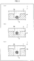
- FIG. 3 are each a cross-sectional view illustrating a different opening formed in the in-mold foamed molded product 4, in accordance with Embodiment 1.
- FIG. 3 is a cross-sectional view taken along the line A-A' indicated in Fig. 2 .
- FIG. 3 illustrates a case where (i) the at least one opening 6 provided to the in-mold foamed molded product 4 (see Fig. 2 ) is a blind hole 6a and (ii) a portion of the insert material 3 is inset into a bottom of the blind hole 6a.
- the blind hole 6a exposes the insert material 3 to the outside of the in-mold foamed molded product 4.
- the blind hole 6a is a recess which does not pass through the in-mold foamed molded product 4.
- the insert material 3 is inset into the bottom of the blind hole 6a, and only an upper side of an exposed part of the insert material 3 exposed to the outside of the in-mold foamed molded product 4.
- the insert material 3 is preferably made of a material (such as iron) having a high affinity with the polyurethane foam 2 such that adhesion strength is sufficient. This makes it possible for the exposed section of the insert material 3 and the polyurethane foam 2 to adhere to each other.
- FIG. 3 illustrates a case where (i) the at least one opening 6 provided to the in-mold foamed molded product 4 (see Fig. 2 ) is a blind hole 6a and (ii) the insert material 3 is distanced from the bottom of the blind hole 6a.
- the blind hole 6a exposes the insert material 3 to the outside of the in-mold foamed molded product 4.
- the insert material 3 is distanced from the bottom of the blind hole 6a such that the insert material 3 is exposed to the outside of the in-mold foamed molded product 4, from a top end of the insert material 3 to a bottom end of the insert material 3.
- this configuration makes it possible to increase the area of contact between the insert material 3 and the polyurethane foam 2.
- This configuration also makes it possible for the polyurethane foam 2 to envelop the insert material 3. This makes the polyurethane foam 2 less likely to become separated from the exposed section of the insert material 3.
- FIG. 3 illustrates a case where an opening provided to an in-mold foamed molded product 4a (variation of the in-mold foamed molded product 4) is a through hole 6b.
- the through hole 6b exposes the insert material 3 to the outside of the in-mold foamed molded product 4a.
- the through hole 6b passes through the in-mold foamed molded product 4a. Furthermore, the insert material 3 is exposed to the outside of the in-mold foamed molded product 4a, from a top end of the insert material 3 to a bottom end of the insert material 3. In comparison to the configuration of (b) of Fig. 3 , this further increases the strength of adhesion between the insert material 3 and the polyurethane foam 2. Because the through hole 6b passes through the in-mold foamed molded product 4a, the portion of the polyurethane foam 2 surrounding the exposed section of the insert material 3 has a greater thickness. This decreases the risk of the polyurethane foam 2 breaking and therefore increases the strength of adhesion between the insert material 3 and the polyurethane foam 2. This configuration also makes it possible for the polyurethane foam 2 to envelop the insert material 3.
- FIG. 4 is a plan view illustrating yet another in-mold foamed molded product unit in accordance with Embodiment 1.
- (b) of Fig. 4 is a cross-sectional view of the foamed composite molded product illustrated in (a) of Fig. 4 , in accordance with Embodiment 1.
- the in-mold foamed molded product 4b is a variation of the in-mold foamed molded product 4.
- the in-mold foamed molded product 4b is structured such that its perimeter has a cutout portion at which the insert material 3 is exposed.
- (b) of Fig. 4 is a cross-sectional view taken along the line D-D' indicated in (a) of Fig. 4 . As illustrated in (b) of Fig.
- portions of the insert material 3 exposed to the outside of the in-mold foamed molded product 4b are covered, along their perimeters, by the polyurethane foam 2.
- This configuration makes it possible for those portions of the insert material 3 which are protruding from the in-mold foamed molded product 4b to adhere with the polyurethane foam 2.
- This configuration also makes it possible for the polyurethane foam 2 to envelop those portions of the insert material 3 which are protruding from the in-mold foamed molded product 4b.
- This configuration makes it possible to increase the area of contact between the insert material 3 and the polyurethane foam 2. The configuration therefore makes it possible to make the polyurethane foam 2 less likely to become separated from the insert material 3.
- a larger diameter of the insert material 3 enables an increased area of contact between the insert material 3 and the polyurethane foam 2.
- increasing the diameter of the insert material 3 leads to an increase in the weight of the insert material 3.
- Such an increase in weight would increase the weight of the vehicle seat and thus be contrary to one of the objectives to be attained, which is the reduction of vehicle weight.
- the diameter of the wire is preferably not less than 0.1 mm and not more than 10.0 mm, and further preferably not less than 3.0 mm and not more than 5.0 mm.
- the insert material 3 is a wire which is made of iron and configured to be hollow inside so as to be in the form of a pipe
- the outer diameter of the pipe is preferably not less than 6.0 mm and not more than 20.0 mm, and more preferably not less than 8.0 mm and not more than 13.0 mm.
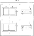
- FIG. 5 are each a plan view illustrating an in-mold foamed molded product unit in accordance with Embodiment 2 .
- FIG. 5 are each a cross-sectional view of the foamed composite molded product illustrated in (a) of Fig. 5 and (c) of Fig. 5 , respectively, in accordance with Embodiment 2 .
- (a) and (b) of Fig. 5 are part of the claimed invention, and (c) and (d) of Fig. 5 are not part of the claimed invention.
- FIG. 5 each illustrate a configuration in which an in-mold foamed molded product 4 is divided into two.
- the in-mold foamed molded product 4 is split into two parts (i.e., two molded body pieces 4A and 4B) at a boundary dividing the in-mold foamed molded product 4.
- a portion of the in-mold foamed molded product 4 has been cut out at a boundary dividing the in-mold foamed molded product 4 into two.
- FIG. 5 illustrates a case where the in-mold foamed molded product 4 is split into two molded body pieces 4A and 4B.
- the insert material 3 is in the form of a loop embedded so as to be in both of the molded body pieces 4A and 4B.
- Splitting the in-mold foamed molded product 4 into two parts in this manner causes the insert material 3 exposed to the outside of the in-mold foamed molded product 4 at a gap formed by two of a plurality of molded body pieces into which the in-mold foamed molded product 4 is split.
- a gap formed by two refers to a gap between two molded body pieces.
- the insert material 3 is exposed to the outside of the in-mold foamed molded product 4 at two positions.
- the portions of the insert material 3 exposed to the outside of the in-mold foamed molded product 4 come into contact with the polyurethane foam 2.
- the in-mold foamed molded product 4 may also be split into three or more parts. That is, the in-mold foamed molded product 4 may be split so as to include three or more molded body pieces.
- FIG. (b) of Fig. 5 is a cross-sectional view taken along the line B-B' indicated in (a) of Fig. 5 .
- portions of the insert material 3 exposed to the outside of the in-mold foamed molded product 4 are covered, along their perimeters, by the polyurethane foam 2. This allows the polyurethane foam 2 to be in contact with the exposed portions of the insert material 3 along an entire perimeter of the exposed portions and therefore makes it possible to improve adhesion between the in-mold foamed molded product unit 5 and the polyurethane foam 2.
- FIG. 5 illustrates a configuration in which a portion of the in-mold foamed molded product 4 is cut out so as to provide a groove which transects one of two opposing sides of a rectangle corresponding to an outline of the insert material 3.
- a portion of the in-mold foamed molded product 4 is cut out at the boundary dividing the in-mold foamed molded product 4 into two.
- the in-mold foamed molded product 4 is not completely split into two parts. This reduces the risk of the polyurethane foam 2 breaking at the split portion of the in-mold foamed molded product 4 when the polyurethane foam 2 is formed on the in-mold foamed molded product unit 5.
- a shape such as that illustrated in (a) of Fig. 5 is preferable, and in terms of securing strength of the polyurethane foam, a shape such as that illustrated in (c) of Fig. 5 is preferable.
- the in-mold foamed molded product 4 can be divided along two or more boundaries.
- the in-mold foamed molded product 4 can include a groove such as that described above at two or more positions.
- FIG. 5 is a cross-sectional view taken along the line C-C' indicated in (c) of Fig. 5 .
- a portion of the insert material 3 is covered by the in-mold foamed molded product 4 along the perimeter of that portion
- a portion of the insert material 3 is covered by the polyurethane foam 2 along the perimeter of that portion.
- the portion of the insert material 3 covered by the in-mold foamed molded product 4 does not come into contact with the polyurethane foam 2.
- the portion of the insert material 3 which is exposed to the outside of the in-mold foamed molded product 4 enables contact with the polyurethane foam 2.
- vision width is also used to describe the width of the groove provided by cutting out a portion of the in-mold foamed molded product 4. In a case where the distance by which the molded body pieces 4A and 4B are separated is not uniform, or in a case where the width of the groove is not uniform, the term “division width” refers to a dimension equivalent to the greatest distance or width.
- a larger division width is more preferable.
- an excessively large division width brings about the risk of a reduction in the cushioning property or strength of the foamed composite molded product 1.
- the division width is adjusted as necessary.
- a larger size of the in-mold foamed molded product 4 enables a larger division width. As such, there is no upper limit to the division width.
- the division width is, for example, preferably not less than 1.0 mm and not more than 150.0 mm, more preferably not less than 5.0 mm and not more than 30.0 mm, and even more preferably not less than 5.0 mm and not more than 15.0 mm.
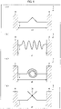
- Fig. 6 consists of diagrams each illustrating an exposed section of an insert material in accordance with Embodiment 3 of the present invention.
- the total length of a portion of an insert material 3, which portion is exposed to the outside of an in-mold foamed molded product 4 is greater than the length (distance a1) of an imaginary straight line segment connecting both ends of that portion.
- Fig. 6 illustrates examples of this.
- FIG. 6 illustrates a case where the insert material 3 is bent such that a center of an exposed section of the insert material 3 protrudes in the shape of a triangular protrusion.
- a configuration as illustrated in (a) of Fig. 6 in which the center of the exposed section of the insert material 3 is in the shape of a triangular protrusion, increases the area of contact between the insert material 3 and polyurethane foam 2.
- a case where the exposed section of the insert material 3 is a straight line can also be described as a case where the total length of the exposed section of the insert material 3 is equal to the distance a1.
- the above configuration improves the adhesion strength between the insert material 3 and the polyurethane foam 2 and also makes it possible to improve the adhesion strength between the in-mold foamed molded product 4 and the polyurethane foam 2.
- the protrusion is not limited to being triangular and may instead be, for example, semicircular or rectangular.
- FIG. 6 illustrates a case where the exposed section of the insert material 3 is bent into a curved line such that the exposed section has a wave-like shape.
- Configuring the exposed section of the insert material 3 to have a wave-like shape increases the area of contact between the insert material 3 and the polyurethane foam 2, similarly to the case illustrated in (a) of Fig. 6 .
- the above configuration improves the adhesion strength between the insert material 3 and the polyurethane foam 2 and also makes it possible to improve the adhesion strength between the in-mold foamed molded product 4 and the polyurethane foam 2.
- the area of contact between the insert material 3 and the polyurethane foam 2 is greater than in the configuration illustrated in (a) of Fig. 6 .
- the configuration illustrated in (b) of Fig. 6 makes it possible to improve adhesion strength between the in-mold foamed molded product 4 and the polyurethane foam 2 even more than does the configuration illustrated in (a) of Fig. 6 .
- a greater area of adhesion between an exposed section of the insert material 3 and the polyurethane foam 2 enables a greater improvement of the adhesion strength between the in-mold foamed molded product 4 and the polyurethane foam 2.
- the exposed section of the insert material 3 may be spiral-shaped instead of being wave-like.
- FIG. 6 illustrates a case where the exposed section of the insert material 3 is curled a number of times so as to have a coiled shape.
- Configuring the exposed section of the insert material 3 to have a coiled shape, as illustrated in (c) of Fig. 6 increases the area of contact between the insert material 3 and the polyurethane foam 2.
- the configuration of (c) of Fig. 6 brings about effects similar to those of (a) and (b) of Fig. 6 .
- FIG. 6 illustrates a case where a first end of the insert material 3 which is exposed to the outside of the in-mold foamed molded product 4 is in mutual contact with a second end of the insert material 3 which is also exposed to the outside of the in-mold foamed molded product 4, and the first and second ends are attached to each other by being welded at their point of contact.
- the insert material 3 has a shape including a portion (a welding point 3a) where the first and second ends of the insert material 3 are attached to each other. In this configuration, the first end of the insert material 3 and/or the second end of the insert material 3 are/is bent. This increases the area of contact between the insert material 3 and the polyurethane foam 2.
- the configuration of (d) of Fig. 6 brings about effects similar to those of (a), (b), and (c) of Fig. 6 .
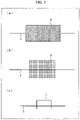
- Fig. 7 consists of diagrams each illustrating an example in which a structure is attached to an exposed section of an insert material, in accordance with Embodiment 4 of the present invention.
- FIG. 7 is a side view of a structure 8 attached to an exposed part of an insert material 3.
- the structure 8 which is rectangular in a side view thereof, is attached to a center of the exposed part of the insert material 3.
- the structure 8 may have a rectangular parallelepiped shape.
- the structure 8 may alternatively have a cylindrical shape.
- the material of the structure 8 is not particularly limited. However, the material of the structure 8 is preferably a metal, because a metal can be easily obtained and easily processed. Because polyurethane foam 2 can envelop the structure 8, it is possible to make the polyurethane foam 2 less likely to become separated from an in-mold foamed molded product unit 5. In particular, in a case where the material of the structure 8 attached to the exposed part of the insert material 3 has a high affinity with the polyurethane foam 2 and provides sufficient adhesion strength (for example, if the material of the structure 8 is iron), the structure 8 and the polyurethane foam 2 will adhere to each other.
- this configuration makes it possible to provide a new region of adhesion, between the polyurethane foam 2 and the structure 8. As such, this configuration increases the area of adhesion between an in-mold foamed molded product unit 5 and the polyurethane foam 2 and makes it possible to improve the adhesion strength therebetween.
- the material of the structure 8 preferably has high affinity with the polyurethane foam 2 such that adhesion strength between the structure 8 and the polyurethane foam 2 is high.
- the material of the structure 8 can be iron. This makes it possible for the structure 8 and the polyurethane foam 2 to adhere to each other. As such, it is possible to improve adhesion between the in-mold foamed molded product unit 5 and the polyurethane foam 2.
- FIG. 7 illustrates a case where a structure attached to the insert material 3 is mesh-like. As illustrated in (b) of Fig. 7 , a structure 9, which is mesh-like, is attached to the center of the exposed part of the insert material 3.
- the polyurethane foam 2 In a case where the polyurethane foam 2 envelops the structure 9, because the structure 9 is mesh-like, the polyurethane foam 2 enters into the mesh. This makes it possible to make the polyurethane foam 2 less likely to become separated from the structure 9 attached to the insert material 3.
- the material of the structure 9 in a case where the material of the insert material 3 does not exhibit adhesion with the polyurethane foam 2, the material of the structure 9 preferably has high affinity with the polyurethane foam 2 such that adhesion strength with the polyurethane foam 2 is high.
- the material of the structure 9 attached to the exposed part of the insert material 3 can be iron.
- FIG. 7 illustrates a case where a structure 7, which is U-shaped and made of the same material as the insert material 3, is adhered to the center of the exposed section of the insert material 3.
- this configuration increases the area of contact between the insert material 3 and the polyurethane foam 2.
- the configuration improves the adhesion strength between the insert material 3 and the polyurethane foam 2 and also makes it possible to improve the adhesion strength between the in-mold foamed molded product 4 and the polyurethane foam 2.
- the material of the structure 7 may differ from the material of the insert material 3.
- the material of the structure 7 is not particularly limited. However, as with the configurations of (a) and (b) of Fig. 7 , it is preferable that at least one of the insert material 3 and the structure 7 be made of a material having a high affinity with the polyurethane foam 2.
- a foamed composite molded product 1 (including an in-mold foamed molded product unit 5 and polyurethane foam 2) was made, and a tension test was carried out on urethane.
- Examples 1, 2, and 3 correspond to (a), (b), and (c) of Fig. 8 , respectively.
- Table 1 below indicates the conditions and results of the urethane tension test.
- L-EPP36 manufactured by Kaneka Corporation; ethylene-propylene random copolymer resin; bulk density: 20 g/L; melting point: 146°C.
- the L-EPP was impregnated with pressurized air such that internal pressure of the L-EPP was approximately 0.1 MPa(G).
- a blind hole 6a was formed by transference of the shape of a mold.
- the blind hole 6a had a diameter of 27.5 mm and a depth of 30.0 mm.
- An in-mold foamed molded product unit was prepared such that an iron wire 3 (insert material 3) was exposed by the blind hole 6a.
- the iron wire 3 had a thickness so as to be 4.0 mm in diameter. In a case where the wire 3 (insert material 3) is in contact with the bottom of the blind hole 6a, as illustrated in (a) of Fig. 8 , the position of the wire 3 will be described as being 0 mm.
- the polyurethane foam 2 was formed in the blind hole 6a so as to be in contact with the wire 3, the wire 3 being exposed by the blind hole 6a of the in-mold foamed molded product unit 5 produced.
- Used as a urethane liquid was undiluted soft urethane liquid (Toyo Soflan R).
- the foamed composite molded product 1 was thus obtained, and a tension test was carried out on the polyurethane foam 2 thereof. Specifically, the polyurethane foam 2 was subjected to a tension test in which tensile speed was 3.0 mm/s, and maximum load was measured.
- Example 2 is similar to Example 1, except that a wire 3 (insert material 3) and an EPP molded product 4 were integrally molded such that the wire 3 was distanced from the bottom of a blind hole 6a by a distance A1 (13 mm), as illustrated in (b) of Fig. 8 .
- a foamed composite molded product was thus produced, and a tension test was carried out on polyurethane foam 2 thereof.
- the present Example is not limiting and that there is no particular lower limit to the distance A1.
- the distance A1 is preferably not less than 1 mm. This is because in a case where the distance A1 is excessively small, the polyurethane foam 2 will not be able to get into a position deeper than the wire 3.
- An upper limit of the distance A1 is set by the depth of the blind hole 6a, and as such is not particularly limited. Note, however, that in a case where a portion of a passenger's body is to be positioned above the blind hole 6a, the wire 3 is preferably positioned so as not to be above an upper surface in the periphery of the blind hole 6a (i.e., not above a surface of the EPP molded product 4 excluding the blind hole 6a). This is so as to avoid a reduction in the comfort of the passenger.
- a lower limit of a distance A2 is not particularly limited. However, the distance A2 is preferably not less than 1 mm, so as to allow the polyurethane foam 2 to enter a space between the wire 3 and the EPP molded product 4.
- An upper limit of the distance A2 is set by the diameter of the blind hole 6a, and as such is not particularly limited.
- Example 2 enabled an increase in the area of adhesion between the wire 3 and the urethane and thus enabled an improvement in the adhesion strength between the wire 3 and the urethane. As such, when the urethane was tensioned, the urethane broke near the wire 3, and thus portions of the urethane at a position deeper than the wire 3 remained.
- Example 2 it is possible for the urethane to envelop the wire 3, and it is therefore possible to make the urethane less likely to become separated from the wire 3.
- the word "adhere” is used to refer to a state in which the urethane does not become separated from the wire 3 when the urethane is tensioned with a tensile load whose strength exceeds 2.75 kgf.
- Example 3 two wires 3 and 3 (insert material 3) were exposed by a single blind hole 6a, as illustrated in (c) of Fig. 8 .
- a foamed composite molded product was produced similarly to that of Example 2, except that there were two wires 3 and 3 provided so as to be distanced from the bottom of the blind hole 6a by a distance A1 (13 mm) and distanced from each other by a distance A3 (2.5 mm).
- a tension test was carried out on polyurethane foam 2 as in Example 2. Note that the present Example is not limiting and that there is no particular lower limit to the distance A3. However, the distance A3 is preferably not less than 1 mm, so that the polyurethane foam 2 can enter a space between the two wires 3 and 3.
- An upper limit of the distance A3 is set by the diameter of the blind hole 6a, and as such is not particularly limited.
- the foamed composite molded product 1 may include three or more wires 3. At least one of the two wires 3, or at least one of the three or more wires 3, may be distanced from the bottom of the blind hole 6a (that is, one or more of the wires 3 may be configured so as not to be distanced from the bottom of the blind hole 6a).
- Example 3 the configuration including two wires 3 enables an increase in the area of adhesion between the wires 3 and the urethane and thus enables an improvement in the adhesion strength between the wires 3 and the urethane.
- the urethane it is possible for the urethane to envelop the two wires 3 exposed by the blind hole 6a, and it is therefore possible to make the urethane less likely to become separated from the wires 3.
- a foamed composite molded product 1 was produced similarly to that of Example 1, except that no wire 3 was used.
- a tension test was carried out on polyurethane foam 2 as in Example 1.
- a foamed composite molded product in accordance with an embodiment of the present invention is defined in claim 1.
- the insert material provided integrally with the in-mold foamed molded product is exposed. This makes it possible for the exposed part of the insert material to adhere to the polyurethane foam. It is also possible for the polyurethane foam to envelop the exposed part of the insert material.
- used as a material of the insert material is a material which has better adhesion with the polyurethane foam than does the in-mold foamed molded product.
- the in-mold foamed molded product unit including an in-mold foamed molded product and an insert material which are integrally provided.
- the insert material preferably has a higher strength than the in-mold foamed molded product.
- the foamed composite molded product is configured such that the portion of the insert material which portion is exposed to the outside of the in-mold foamed molded product is exposed by at least one selected from the group consisting of: (1) a blind hole formed in the in-mold foamed molded product; (2) a through hole formed in the in-mold foamed molded product; (3) a gap formed by two of a plurality of molded body pieces, the plurality of molded body pieces being obtained by dividing the in-mold foamed molded product.
- the above configuration makes it possible to easily expose, to the outside of the in-mold foamed molded product, at least a portion of the insert material integrally provided with the in-mold foamed molded product.
- the foamed composite molded product may be configured such that the portion of the insert material which portion is exposed to the outside of the in-mold foamed molded product has a total length which is greater than a length of an imaginary straight line segment connecting both ends of the portion.
- the foamed composite molded product may be configured such that: the portion of the insert material which portion is exposed to the outside of the in-mold foamed molded product is exposed by the blind hole formed in the in-mold foamed molded product; and at least a part of the portion of the insert material which portion is exposed to the outside of the in-mold foamed molded product is enveloped by the polyurethane foam.
- the foamed composite molded product may be configured such that the portion of the insert material which portion is exposed to the outside of the in-mold foamed molded product has a surface to which a structure different from the insert material is provided.
- the foamed composite molded product may be configured such that the structure is made of metal.
- the structure is made of metal. This makes it easy to obtain and process the structure.
- the foamed composite molded product may be configured such that the insert material is made of metal.
- the insert material is made of metal. This makes it easy to obtain and process the insert material.
- the foamed composite molded product may be configured such that the insert material is made of a material selected from the group consisting of inorganic fiber, fiber reinforced plastic, fiber reinforced metal, wood, concrete, iron, stainless steel, zinc, and aluminum.
- the insert material is made of a material as described above. This makes is possible for the insert material and the polyurethane foam to adhere to each other with sufficient strength.
- the foamed composite molded product may be configured such that the insert material and the polyurethane foam are adhered to each other.
- the insert material and the polyurethane foam are adhered to each other. This makes it possible to increase the strength of adhesion between an in-mold foamed molded product unit and polyurethane foam, in comparison to a case where polyurethane foam is adhered only to an in-mold foamed molded product.
- the foamed composite molded product may be configured such that the in-mold foamed molded product and the polyurethane foam are not adhered to each other.
- the foamed composite molded product may be configured such that at least a portion of a surface of the in-mold foamed molded product is not covered by the polyurethane foam and is exposed.
- the foamed composite molded product may be configured such that the in-mold foamed molded product is made of an olefin resin.
- a method of producing a foamed composite molded product in accordance with an embodiment of the present invention is defined in claim 12.
- the method makes it possible to provide a foamed composite molded product in which polyurethane foam is unlikely to become separated from an in-mold foamed molded product unit.
Landscapes
- Engineering & Computer Science (AREA)
- Manufacturing & Machinery (AREA)
- Aviation & Aerospace Engineering (AREA)
- Transportation (AREA)
- Mechanical Engineering (AREA)
- Casting Or Compression Moulding Of Plastics Or The Like (AREA)
- Injection Moulding Of Plastics Or The Like (AREA)
- Moulds For Moulding Plastics Or The Like (AREA)
- Molding Of Porous Articles (AREA)
Description
- The present invention relates to a foamed composite molded product and a method of producing the foamed composite molded product.
- Conventionally, a vehicle seat has typically been produced by providing a seat body made of polyurethane foam in an integrated manner with a metal wire embedded therein. The metal wire serves as an insert material for stabilizing the shape of the vehicle seat. Recently, in view of achieving vehicle weight reduction, cost reduction, and the like, there has been proposed a configuration in which polyurethane foam is combined with an in-mold foamed molded product unit, which is molded from thermoplastic resin. The in-mold foamed molded product unit is obtained by insert molding in which an insert material (for example, a metal wire) is provided in an in-mold foamed molded product, made of thermoplastic resin expanded particles. The in-mold foamed molded product unit is used as a core material of the vehicle seat. The vehicle seat is obtained by providing the in-mold foamed molded product unit integrally with the polyurethane foam and then covering the in-mold foamed molded product unit and the polyurethane foam with a seat cover.
- However, in a case where the in-mold foamed molded product unit and the polyurethane foam are molded integrally, there is the possibility that the in-mold foamed molded product and the polyurethane foam will not adhere to each other and will therefore easily separate. As such, there is a risk of a reduction in passenger comfort occurring due to separation of the in-mold foamed molded product and the polyurethane foam.
- Examples of techniques for solving the above problem include
Patent Literatures 1 to 4. InPatent Literature 1, a surface of a molded product (in-mold foamed molded product) made of thermoplastic resin includes a contact region at which the molded product comes into contact with a different-material layer (polyurethane foam). The contact region is heated to a temperature which is not less than 80% of a softening temperature of the molded product. This heating causes expandable resin particles in the region of contact to soften and expand so as to form unevenness in the region of contact. The different-material layer is provided so as to enter depressions in the unevenness. -
Patent Literature 2 discloses carrying out an adhesiveness-providing treatment, such as a corona discharge treatment or coating with an anchor coat agent, between padding (polyurethane foam) and a foamed molded product (in-mold foamed molded product) made of olefin resin. This increases the adhesion strength between the surface of the foamed molded product and the surface of the padding. -
Patent Literature 3 discloses a configuration in which an opening is provided to a base material layer (in-mold foamed molded product) made of olefin resin. Polyurethane foam enters into the opening in the base material layer. This causes the base material layer and the polyurethane foam to be in close contact over a large area and in a complex manner. As such, the base material layer and the polyurethane foam are unified in a laminar manner with a high bonding strength. -
Patent Literature 4 discloses a configuration in which an outer envelope foam (polyurethane foam) is adhered to a reinforcement foam (in-mold foamed molded product) along the entire surface of the reinforcement foam. - In this way, the in-mold foamed molded products of
Patent Literatures 1 to 4, adhesion to the polyurethane foam has been improved. -
- [Patent Literature 1]
Japanese Patent Application Publication, Tokukai, No. 2012-171104 - [Patent Literature 2]
Japanese Patent Application Publication, Tokukaihei, No. 02-265714 - [Patent Literature 3]
Japanese Patent Application Publication, Tokukai, No. 2015-155146 - [Patent Literature 4]
Japanese Utility Model Application Publication, Jitsukaisho, No. 58-156451 -
US2011221254A1 discloses preambles ofclaims 1 and 12. - The solutions presented in
Patent Literatures 1 to 3 each include a means of improving the adhesion strength between (i) an in-mold foamed molded product made of thermoplastic resin and (ii) polyurethane foam. However, thermoplastic resin by its nature has poor adhesion with polyurethane foam. As such, even though the adhesion strength between the in-mold foamed molded product and the polyurethane foam is improved, the adhesion strength is still insufficient. - The present invention has been accomplished in view of the above problem. An object of the present invention lies in providing (i) a foamed composite molded product in which polyurethane foam is unlikely to become separated from an in-mold foamed molded product unit, the in-mold foamed molded product unit including an in-mold foamed molded product and an insert material which are integrally molded, and (ii) a method of producing the foamed composite molded product.
- In order to solve the above problem, a foamed composite molded product in accordance with an embodiment of the present invention is defined in
claim 1. - With the above configuration, at least a portion of the insert material molded integrally with the in-mold foamed molded product is exposed. This makes it possible for the exposed part of the insert material to adhere to the polyurethane foam. It is also possible for the polyurethane foam to envelop the exposed part of the insert material. As such, used as a material of the insert material is a material which has better adhesion with the polyurethane foam than does the in-mold foamed molded product. This makes it possible to achieve a foamed composite molded product in which polyurethane foam is unlikely to become separated from an in-mold foamed molded product unit, the in-mold foamed molded product unit including an in-mold foamed molded product and an insert material which are integrally molded. Note that the insert material preferably has a higher strength than the in-mold foamed molded product.
- A method of producing a foamed composite molded product in accordance with an embodiment of the present invention is defined in claim 12.
- With the above method, at least a portion of the insert material integrally molded with the in-mold foamed molded product is adhered to the polyurethane foam and/or enveloped by the polyurethane foam. As such, the method makes it possible to provide a foamed composite molded product in which polyurethane foam is unlikely to become separated from an in-mold foamed molded product unit.
- The present invention, defined in
claims 1, 12, brings about an effect of making polyurethane foam unlikely to become separated from an in-mold foamed molded product unit, the in-mold foamed molded product unit including an in-mold foamed molded product and an insert material which are integrally molded. -
-
Fig. 1 is an external lateral view illustrating a foamed composite molded product in accordance with an embodiment which is not part of the claimed invention. -
Fig. 2 is a plan view illustrating a configuration of an in-mold foamed molded product unit in accordance withEmbodiment 1.Fig. 2 exemplarily illustrates a structure in which an insert material is exposed by an opening formed in the in-mold foamed molded product. -
Fig. 3 consists of cross-sectional views each illustrating a different opening formed in the in-mold foamed molded product, which is in with the claimed invention and also in accordance withEmbodiment 1. - (a) of
Fig. 4 is a plan view illustrating yet another in-mold foamed molded product unit in accordance withEmbodiment 1 but not in line with the claimed invention. (b) ofFig. 4 is a cross-sectional view of the foamed composite molded product illustrated in (a) ofFig. 4 , in accordance withEmbodiment 1 but not in line with the claimed invention. - (a) and (c) of
Fig. 5 are each a plan view illustrating an in-mold foamed molded product unit in accordance withEmbodiment 2 . (b) and (d) ofFig. 5 are each a cross-sectional view of the foamed composite molded product illustrated in (a) ofFig. 5 and (c) ofFig. 5 , respectively, in accordance withEmbodiment 2 . - (a) and (b) of
Fig. 5 are part of the claimed invention, and (c) and (d) ofFig. 5 are not part of the claimed invention. -
Fig. 6 consists of diagrams each illustrating an exposed section of an insert material in accordance withEmbodiment 3 of the present
invention. -
Fig. 7 consists of diagrams each illustrating an example in which a structure is attached to an exposed section of an insert material, in accordance withEmbodiment 4 of the present
invention. -
Fig. 8 consists of cross-sectional views each illustrating a variation of the structure illustrated in (b) ofFig. 3 . -
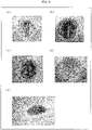
Fig. 9 consists of pictures each showing an example of a state of urethane after a tension test in accordance withEmbodiment 2. - The following description will discuss embodiments of the present disclosure
with reference toFigs. 1 to 7 . - An object of the present invention is to make polyurethane foam less likely to become separated from an in-mold foamed molded product unit. However, adhesion is poor between polyurethane foam and an in-mold foamed molded product made of olefin resin or the like. Furthermore, in a foamed composite molded product for use in a vehicle seat, polyurethane foam is typically formed on a surface of only a part of the in-mold foamed molded product. As such, it is unfeasible to prevent separation of the polyurethane foam from the in-mold foamed molded product by forming the polyurethane foam in a manner so as to envelop the in-mold foamed molded product. After diligent study in view of these issues, the inventors of the present invention arrived at the following techniques.
-
Fig. 1 is an external lateral view illustrating a foamed composite molded product. - As illustrated in
Fig. 1 , a foamed composite moldedproduct 1 includespolyurethane foam 2 and an in-mold foamed moldedproduct unit 5 which have been molded integrally with each other. The in-mold foamed moldedproduct unit 5 includes aninsert material 3 and an in-mold foamed molded product constituted by thermoplastic resin expanded particles. In the example illustrated inFig. 1 , an in-mold foamed moldedproduct 4, constituted by polyolefin-based resin expanded particles, is molded integrally with theinsert material 3. The foamed composite moldedproduct 1 can be produced by forming thepolyurethane foam 2 so as to be in contact with a portion of theinsert material 3, which portion is exposed to the outside of the in-mold foamed moldedproduct 4. This is illustrated in more detail inFig. 2 onward. The in-mold foamed molded product is preferably made of polyolefin resin. - In a case where, for example, the foamed composite molded
product 1 is to be mounted to a vehicle, thepolyurethane foam 2 is preferably (i) formed on at least a surface of the in-mold foamed moldedproduct 4 which surface is on a side away from a vehicle-mounting side of the in-mold foamed moldedproduct 4 but (ii) not formed on a surface on the vehicle-mounting side. That is, as illustrated inFig. 1 , thepolyurethane foam 2 may be formed so as to cover only a portion of the in-mold foamed moldedproduct 4. In other words, as illustrated inFig. 1 , at least a portion of the surface of the in-mold foamed moldedproduct 4 may be left uncovered by thepolyurethane foam 2 so as to be exposed. For example, thepolyurethane foam 2 may be formed in a manner so as to be formed on afirst surface 41 of the in-mold foamed moldedproduct 4 but not to asecond surface 42 of the in-mold foamed moldedproduct 4, whichsecond surface 42 is on a reverse side with respect to thefirst surface 41. - The
insert material 3 is provided inside the in-mold foamed moldedproduct 4. Theinsert material 3 may be made of any of a variety of materials, provided that theinsert material 3 is stronger against breakage (i.e., has a higher tensile strength) than the in-mold foamed moldedproduct 4. In other words, theinsert material 3 may be made of any of a variety of materials provided that theinsert material 3 is harder than the in-mold foamed moldedproduct 4, or, if the material of theinsert material 3 is softer than the in-mold foamed moldedproduct 4, provided that theinsert material 3 is less easily broken than the in-mold foamed moldedproduct 4. Theinsert material 3 is preferably made of a material having high affinity with thepolyurethane foam 2. Possible examples of materials for theinsert material 3 include metal, inorganic fiber (carbon fiber, glass fiber, and the like), fiber reinforced plastic (carbon fiber reinforced plastic, glass fiber reinforced plastic, and the like), fiber reinforced metal, wood, and concrete. Out of these examples, metal wire is preferable as the material of theinsert material 3. Examples of metals which can be used for theinsert material 3 include iron, stainless steel, zinc, and aluminum. - A base material resin used for the thermoplastic resin expanded particles is not particularly limited. Possible examples include polyolefin resin, polystyrene resin, styrene-modified polyolefin resin (olefin-modified polystyrene resin), and polyester resin. Out of these examples, the use of an olefin resin such as polyolefin resin or styrene-modified polyolefin resin, and more preferably the use of polyolefin resin, provides a superior shock-absorbing property, chemical resistance, heat resistance, and strain recovery rate after compression, and allows for easy recycling.
- The polyolefin resin is not particularly limited. Possible examples include polypropylene resin and polyethylene resin. Examples of the polypropylene resin include a propylene homopolymer, an ethylene/propylene copolymer, and an ethylene/propylene/1-butene copolymer. Examples of the polyethylene resin include an ethylene homopolymer, high density polyethylene resin, medium density polyethylene resin, low density polyethylene resin, and linear low-density polyethylene resin. Specific examples include an ethylene/1-butene copolymer and an ethylene/4-methyl-1-pentene copolymer. The ethylene/propylene copolymer, the ethylene/propylene/1-butene copolymer, the ethylene/1-butene copolymer, and the ethylene/4-methyl-1-pentene copolymer can each be a random copolymer or a block copolymer.
- A method of producing the expanded particle is not particularly limited. A conventionally known production method can be employed. For example, in the case of polyolefin-based resin expanded particles, possible examples of the production method include the methods disclosed in International Patent Application Publication No.
WO 2009/075208 ,Japanese Patent Application Publication, Tokukai, No. 2006-117842 Japanese Patent Application Publication, Tokukai, No. 2003-201360 Japanese Patent Application Publication, Tokukai, No. 2014-118474 WO 2015/137363 , and the like. These documents describe expanded particles as pre-expanded particles. In the case of styrene-modified polyolefin-based resin expanded particles, possible examples of the production method include the methods disclosed inJapanese Patent Application Publication, Tokukai, No. 2008-239794 WO2016/152243 , and the like. Note that the method of producing the expanded particles is not limited to the above methods. - Expanded particles obtained via the above methods can be made to include or be coated with an additive as necessary by use of a conventionally known method. Examples of such an additive include a flame retarder, an anti-static agent, and a colorant. Particle size of the expanded particles is not particularly limited and can be, for example, 1 mm to 10 mm. In terms of a mold-filling property, the particle size is preferably 1 mm to 5 mm and more preferably 1 mm to 3 mm.
- The expansion ratio of the expanded particles is not particularly limited and can be, for example, 3 times to 90 times. In terms of mechanical strength and moldability, the expansion ratio is preferably 5 times to 60 times and more preferably 5 times to 45 times.
- Expanded particles as described above are commercially available as, for example, EPERAN-PP and EPERAN-XL (manufactured by Kaneka Corporation), and are easily acquired.
- In the present disclosure, for convenience, the in-mold foamed molded
product 4 is hereinafter described as being an in-mold foamed molded product made of polyolefin-based resin expanded particles. The in-mold foamed moldedproduct 4 is molded, with use of a mold apparatus for in-mold foam molding, by heating polyolefin-based resin expanded particles so as to expand the particles and cause them to be fused to each other. A detailed description is as follows. - The mold apparatus for in-mold foam molding includes (i) a concave mold unit having a concave mold and a concave mold housing which holds the concave mold and (ii) a convex mold unit having a convex mold and a convex mold housing which holds the convex mold. The concave mold and the convex mold form a space when closed together. Polyolefin-based resin expanded particles are filled into this space. The expanded particles may have an inorganic gas or the like impregnated therein beforehand so as to increase internal pressure, or may be expanded particles which are at atmospheric pressure and not internally pressurized. After the polyolefin-based resin expanded particles are filled into the space, saturated steam pressure of approximately 0.04 MPa(G) to 0.40 MPa(G) is supplied to chambers respectively provided to the concave mold housing and the convex mold housing. This heats the polyolefin-based resin expanded particles so as to expand the particles and cause them to be fused to each other. In this way, the in-mold foamed molded
product 4 is obtained by in-mold foam molding of the polyolefin-based resin expanded particles. - The in-mold foamed molded
product unit 5 is obtained by providing theinsert material 3 to the convex mold or the concave mold of the mold apparatus for the in-mold foamed molded product and carrying out the above technique for producing the in-mold foamed molded product, such that the in-mold foamed moldedproduct 4 is molded integrally with theinsert material 3. The in-mold foamed moldedproduct unit 5 can be used as, for example, a core material for a vehicle seat. A vehicle seat can be obtained by molding the in-mold foamed moldedproduct unit 5 and thepolyurethane foam 2 integrally and then covering the in-mold foamed moldedproduct unit 5 and thepolyurethane foam 2 with a seat cover. - In order to improve adhesion between the
polyurethane foam 2 and the in-mold foamed moldedproduct unit 5, prepared firstly is a unit in which the in-mold foamed moldedproduct 4 is molded integrally with theinsert material 3 such that theinsert material 3 is inside the in-mold foamed moldedproduct 4. A portion of theinsert material 3 is exposed to the outside of the in-mold foamed molded product 4 (step of preparing in-mold foamed molded product unit). As such, the portion of theinsert material 3 which is exposed to the outside of the in-mold foamed moldedproduct 4 comes into contact with the polyurethane foam 2 (step of providing the polyurethane foam such that the polyurethane foam is in contact with the portion exposed to the outside of the in-mold foamed molded product of the in-mold foamed molded product unit). Hereinafter, the portion of theinsert material 3 which is exposed to the outside of the in-mold foamed moldedproduct 4 is also referred to as an "exposed section". Thepolyurethane foam 2 and theinsert material 3 of the in-mold foamed moldedproduct unit 5 adhere to each other favorably when there is a high affinity between them. This makes it possible to improve the adhesion strength between thepolyurethane foam 2 and the in-mold foamed moldedproduct unit 5. The foamed composite moldedproduct 1 is obtained by adhering thepolyurethane foam 2 and the in-mold foamed moldedproduct unit 5 together (method of producing the foamed composite molded product). - In other words, the foamed composite molded
product 1 in accordance with an embodiment of the present invention is configured such that (i) at least a portion of theinsert material 3 is exposed to the outside of the in-mold foamed moldedproduct 4 and (ii) at least a portion of theinsert material 3 is in contact with thepolyurethane foam 2. -
Fig. 2 is a plan view illustrating a configuration of an in-mold foamed molded product unit in accordance withEmbodiment 1.Fig. 2 exemplarily illustrates a structure in which an insert material is exposed by an opening (or hole) formed in the in-mold foamed molded product.Fig. 2 illustrates a portion of an in-mold foamed moldedproduct 4 which portion comes into contact withpolyurethane foam 2. - As illustrated in
Fig. 2 , at least oneopening 6 is formed in an in-mold foamed moldedproduct 4. The at least oneopening 6 exposes a portion of aninsert material 3. The portion of theinsert material 3 exposed by the at least oneopening 6 comes into contact with thepolyurethane foam 2. This makes it possible to improve adhesion between thepolyurethane foam 2 and an in-mold foamed moldedproduct unit 5. - The at least one
opening 6 is provided to at least one position on the in-mold foamed moldedproduct 4. Furthermore, the at least oneopening 6 includes at least oneopening 6 provided at a position such that theinsert material 3 comes into contact with thepolyurethane foam 2. In consideration of adhesion between theinsert material 3 and thepolyurethane foam 2, the at least one opening is preferably plural in number and large in size. The number, shape, and size of the at least one opening are not particularly limited but can be adjusted as necessary in consideration of the desired strength and cushioning property of a foamed composite moldedproduct 1. A larger size of the in-mold foamed moldedproduct 4 enables a larger size of the at least oneopening 6. As such, there is no upper limit to the size of the at least oneopening 6. However, in terms of enabling wide use, the diameter of the at least oneopening 6 is, for example, preferably not less than 1.0 mm and not more than 200.0 mm, more preferably not less than 5.0 mm and not more than 30.0 mm, and even more preferably not less than 5.0 mm and not more than 20.0 mm. In a case where the shape of the at least oneopening 6 does not allow for description in terms of diameter, the diameter is considered to be a dimension at which distance is greatest along an unobstructed straight line between two points on the perimeter of the at least oneopening 6. - The shape of the at least one
opening 6 can be a shape other than the circular shape illustrated inFig. 2 . For example, the at least oneopening 6 can be shaped so as to be elliptical or polygonal (rectangular, rhombic, triangular, star-shaped, L-shaped, cross-shaped, etc.). Furthermore, the at least oneopening 6 may include at least one protrusion which protrudes from a bottom surface or from an inner wall of the at least oneopening 6. - (a) to (c) of
Fig. 3 are each a cross-sectional view illustrating a different opening formed in the in-mold foamed moldedproduct 4, in accordance withEmbodiment 1. Each of (a) to (c) ofFig. 3 is a cross-sectional view taken along the line A-A' indicated inFig. 2 . - (a) of
Fig. 3 illustrates a case where (i) the at least oneopening 6 provided to the in-mold foamed molded product 4 (seeFig. 2 ) is ablind hole 6a and (ii) a portion of theinsert material 3 is inset into a bottom of theblind hole 6a. In other words, in the illustrated configuration, theblind hole 6a exposes theinsert material 3 to the outside of the in-mold foamed moldedproduct 4. - As illustrated in (a) of
Fig. 3 which is in line with the claimed invention, theblind hole 6a is a recess which does not pass through the in-mold foamed moldedproduct 4. Theinsert material 3 is inset into the bottom of theblind hole 6a, and only an upper side of an exposed part of theinsert material 3 exposed to the outside of the in-mold foamed moldedproduct 4. With this structure, because thepolyurethane foam 2 cannot envelop theinsert material 3, theinsert material 3 is preferably made of a material (such as iron) having a high affinity with thepolyurethane foam 2 such that adhesion strength is sufficient. This makes it possible for the exposed section of theinsert material 3 and thepolyurethane foam 2 to adhere to each other. - (b) of
Fig. 3 illustrates a case where (i) the at least oneopening 6 provided to the in-mold foamed molded product 4 (seeFig. 2 ) is ablind hole 6a and (ii) theinsert material 3 is distanced from the bottom of theblind hole 6a. In other words, in the illustrated configuration, theblind hole 6a exposes theinsert material 3 to the outside of the in-mold foamed moldedproduct 4. - As illustrated in (b) of
Fig. 3 which is in line with the claimed invention, theinsert material 3 is distanced from the bottom of theblind hole 6a such that theinsert material 3 is exposed to the outside of the in-mold foamed moldedproduct 4, from a top end of theinsert material 3 to a bottom end of theinsert material 3. In comparison to the configuration of (a) ofFig. 3 , this configuration makes it possible to increase the area of contact between theinsert material 3 and thepolyurethane foam 2. This configuration also makes it possible for thepolyurethane foam 2 to envelop theinsert material 3. This makes thepolyurethane foam 2 less likely to become separated from the exposed section of theinsert material 3. - (c) of
Fig. 3 illustrates a case where an opening provided to an in-mold foamed moldedproduct 4a (variation of the in-mold foamed molded product 4) is a throughhole 6b. In other words, in the illustrated configuration, the throughhole 6b exposes theinsert material 3 to the outside of the in-mold foamed moldedproduct 4a. - As illustrated in (c) of
Fig. 3 which is in line with the claimed invention, the throughhole 6b passes through the in-mold foamed moldedproduct 4a. Furthermore, theinsert material 3 is exposed to the outside of the in-mold foamed moldedproduct 4a, from a top end of theinsert material 3 to a bottom end of theinsert material 3. In comparison to the configuration of (b) ofFig. 3 , this further increases the strength of adhesion between theinsert material 3 and thepolyurethane foam 2. Because the throughhole 6b passes through the in-mold foamed moldedproduct 4a, the portion of thepolyurethane foam 2 surrounding the exposed section of theinsert material 3 has a greater thickness. This decreases the risk of thepolyurethane foam 2 breaking and therefore increases the strength of adhesion between theinsert material 3 and thepolyurethane foam 2. This configuration also makes it possible for thepolyurethane foam 2 to envelop theinsert material 3. - Instead of the configuration in which the at least one
opening 6 is provided as illustrated in (a) to (c) ofFig. 3 , it is possible to employ a configuration in which a portion of theinsert material 3 protrudes from a surface of the in-mold foamed moldedproduct 4. In other words, a configuration may be employed in which, as illustrated in (a) ofFig. 4 which is not in line with the claimed invention, theinsert material 3 is exposed to the outside of an in-mold foamed moldedproduct 4b by the perimeter of an outer surface of the in-mold foamed moldedproduct 4b (particularly, such that theinsert material 3 is further outward than an outer contour of the in-mold foamed moldedproduct 4b). (a) ofFig. 4 is a plan view illustrating yet another in-mold foamed molded product unit in accordance withEmbodiment 1. (b) ofFig. 4 is a cross-sectional view of the foamed composite molded product illustrated in (a) ofFig. 4 , in accordance withEmbodiment 1. The in-mold foamed moldedproduct 4b is a variation of the in-mold foamed moldedproduct 4. The in-mold foamed moldedproduct 4b is structured such that its perimeter has a cutout portion at which theinsert material 3 is exposed. (b) ofFig. 4 is a cross-sectional view taken along the line D-D' indicated in (a) ofFig. 4 . As illustrated in (b) ofFig. 4 , portions of theinsert material 3 exposed to the outside of the in-mold foamed moldedproduct 4b are covered, along their perimeters, by thepolyurethane foam 2. This configuration makes it possible for those portions of theinsert material 3 which are protruding from the in-mold foamed moldedproduct 4b to adhere with thepolyurethane foam 2. This configuration also makes it possible for thepolyurethane foam 2 to envelop those portions of theinsert material 3 which are protruding from the in-mold foamed moldedproduct 4b. This configuration makes it possible to increase the area of contact between theinsert material 3 and thepolyurethane foam 2. The configuration therefore makes it possible to make thepolyurethane foam 2 less likely to become separated from theinsert material 3. - A larger diameter of the
insert material 3 enables an increased area of contact between theinsert material 3 and thepolyurethane foam 2. However, increasing the diameter of theinsert material 3 leads to an increase in the weight of theinsert material 3. Such an increase in weight would increase the weight of the vehicle seat and thus be contrary to one of the objectives to be attained, which is the reduction of vehicle weight. As such, in a case where, for example, theinsert material 3 is a wire made of iron, the diameter of the wire is preferably not less than 0.1 mm and not more than 10.0 mm, and further preferably not less than 3.0 mm and not more than 5.0 mm. In a case where, for example, theinsert material 3 is a wire which is made of iron and configured to be hollow inside so as to be in the form of a pipe, the outer diameter of the pipe is preferably not less than 6.0 mm and not more than 20.0 mm, and more preferably not less than 8.0 mm and not more than 13.0 mm. - (a) and (c) of
Fig. 5
are each a plan view illustrating an in-mold foamed molded product unit in accordance withEmbodiment 2 . - (b) and (d) of
Fig. 5
are each a cross-sectional view of the foamed composite molded product illustrated in (a) ofFig. 5 and (c) ofFig. 5 , respectively, in accordance withEmbodiment 2 .
(a) and (b) ofFig. 5 are part of the claimed invention, and (c) and (d) ofFig. 5 are not part of the claimed invention. - (a) to (d) of
Fig. 5 each illustrate a configuration in which an in-mold foamed moldedproduct 4 is divided into two. In (a) ofFig. 5 , the in-mold foamed moldedproduct 4 is split into two parts (i.e., two moldedbody pieces product 4. In (c) ofFig. 5 , a portion of the in-mold foamed moldedproduct 4 has been cut out at a boundary dividing the in-mold foamed moldedproduct 4 into two. - (a) of
Fig. 5 illustrates a case where the in-mold foamed moldedproduct 4 is split into two moldedbody pieces Fig. 5 , theinsert material 3 is in the form of a loop embedded so as to be in both of the moldedbody pieces product 4 into two parts in this manner causes theinsert material 3 exposed to the outside of the in-mold foamed moldedproduct 4 at a gap formed by two of a plurality of molded body pieces into which the in-mold foamed moldedproduct 4 is split. Here, "a gap formed by two" refers to a gap between two molded body pieces. With this configuration, theinsert material 3 is exposed to the outside of the in-mold foamed moldedproduct 4 at two positions. As such, when the in-mold foamed moldedproduct unit 5 and thepolyurethane foam 2 are molded integrally, the portions of theinsert material 3 exposed to the outside of the in-mold foamed moldedproduct 4 come into contact with thepolyurethane foam 2. This makes is possible to improve adhesion between the in-mold foamed moldedproduct unit 5 and thepolyurethane foam 2 and also allows thepolyurethane foam 2 to envelop theinsert material 3. Note that the in-mold foamed moldedproduct 4 may also be split into three or more parts. That is, the in-mold foamed moldedproduct 4 may be split so as to include three or more molded body pieces. - (b) of
Fig. 5 is a cross-sectional view taken along the line B-B' indicated in (a) ofFig. 5 . As illustrated in (b) ofFig. 5 , portions of theinsert material 3 exposed to the outside of the in-mold foamed moldedproduct 4 are covered, along their perimeters, by thepolyurethane foam 2. This allows thepolyurethane foam 2 to be in contact with the exposed portions of theinsert material 3 along an entire perimeter of the exposed portions and therefore makes it possible to improve adhesion between the in-mold foamed moldedproduct unit 5 and thepolyurethane foam 2. - (c) of
Fig. 5 illustrates a configuration in which a portion of the in-mold foamed moldedproduct 4 is cut out so as to provide a groove which transects one of two opposing sides of a rectangle corresponding to an outline of theinsert material 3. As illustrated in (c) ofFig. 5 , at a surface of the in-mold foamed moldedproduct 4 which surface comes into contact with thepolyurethane foam 2, a portion of the in-mold foamed moldedproduct 4 is cut out at the boundary dividing the in-mold foamed moldedproduct 4 into two. With this configuration, theinsert material 3 is exposed to the outside of the in-mold foamed moldedproduct 4 at only one position. As such, when thepolyurethane foam 2 is formed on the in-mold foamed moldedproduct unit 5, the portion of theinsert material 3 exposed to the outside of the in-mold foamed moldedproduct 4 comes into contact with thepolyurethane foam 2. This makes is possible to improve adhesion between the in-mold foamed moldedproduct unit 5 and thepolyurethane foam 2 and also allows thepolyurethane foam 2 to envelop theinsert material 3. With the configuration of (a) ofFig. 5 , theinsert material 3 is exposed to the outside of the in-mold foamed moldedproduct 4 and in contact with thepolyurethane foam 2 at two positions, and adhesion strength is therefore higher in comparison to the configuration of (c) ofFig. 5 . However, with the configuration of (c) ofFig. 5 , the in-mold foamed moldedproduct 4 is not completely split into two parts. This reduces the risk of thepolyurethane foam 2 breaking at the split portion of the in-mold foamed moldedproduct 4 when thepolyurethane foam 2 is formed on the in-mold foamed moldedproduct unit 5. As such, in terms of adhesion with the polyurethane foam, a shape such as that illustrated in (a) ofFig. 5 is preferable, and in terms of securing strength of the polyurethane foam, a shape such as that illustrated in (c) ofFig. 5 is preferable. Note that the in-mold foamed moldedproduct 4 can be divided along two or more boundaries. For example, the in-mold foamed moldedproduct 4 can include a groove such as that described above at two or more positions. - (d) of
Fig. 5 is a cross-sectional view taken along the line C-C' indicated in (c) ofFig. 5 . As illustrated in (d) ofFig. 5 , on a first side, a portion of theinsert material 3 is covered by the in-mold foamed moldedproduct 4 along the perimeter of that portion, and on a second side, a portion of theinsert material 3 is covered by thepolyurethane foam 2 along the perimeter of that portion. With this configuration, on the first side, the portion of theinsert material 3 covered by the in-mold foamed moldedproduct 4 does not come into contact with thepolyurethane foam 2. However, on the second side, the portion of theinsert material 3 which is exposed to the outside of the in-mold foamed moldedproduct 4 enables contact with thepolyurethane foam 2. - In the configuration where the in-mold foamed molded
product 4 is split at the boundary dividing the in-mold foamed moldedproduct 4, a distance by which the moldedbody piece 4A and the moldedbody piece 4B are separated is hereinafter also described as a "division width". The term "division width" is also used to describe the width of the groove provided by cutting out a portion of the in-mold foamed moldedproduct 4. In a case where the distance by which the moldedbody pieces product 1, an excessively large division width brings about the risk of a reduction in the cushioning property or strength of the foamed composite moldedproduct 1. As such, the division width is adjusted as necessary. A larger size of the in-mold foamed moldedproduct 4 enables a larger division width. As such, there is no upper limit to the division width. However, in terms of enabling wide use, the division width is, for example, preferably not less than 1.0 mm and not more than 150.0 mm, more preferably not less than 5.0 mm and not more than 30.0 mm, and even more preferably not less than 5.0 mm and not more than 15.0 mm. -
Fig. 6 consists of diagrams each illustrating an exposed section of an insert material in accordance withEmbodiment 3 of the present
invention. InEmbodiment 3, the total length
of a portion of aninsert material 3, which portion is exposed to the outside of an in-mold foamed moldedproduct 4, is greater than the length (distance a1) of an imaginary straight line segment connecting both ends of that portion.Fig. 6 illustrates examples of this. - (a) of
Fig. 6 illustrates a case where theinsert material 3 is bent such that a center of an exposed section of theinsert material 3 protrudes in the shape of a triangular protrusion. In comparison to a case where the exposed section of theinsert material 3 is a straight line, a configuration as illustrated in (a) ofFig. 6 , in which the center of the exposed section of theinsert material 3 is in the shape of a triangular protrusion, increases the area of contact between theinsert material 3 andpolyurethane foam 2. A case where the exposed section of theinsert material 3 is a straight line can also be described as a case where the total length of the exposed section of theinsert material 3 is equal to the distance a1. The above configuration improves the adhesion strength between theinsert material 3 and thepolyurethane foam 2 and also makes it possible to improve the adhesion strength between the in-mold foamed moldedproduct 4 and thepolyurethane foam 2. Note that the protrusion is not limited to being triangular and may instead be, for example, semicircular or rectangular. - (b) of
Fig. 6 illustrates a case where the exposed section of theinsert material 3 is bent into a curved line such that the exposed section has a wave-like shape. Configuring the exposed section of theinsert material 3 to have a wave-like shape, as illustrated in (b) ofFig. 6 , increases the area of contact between theinsert material 3 and thepolyurethane foam 2, similarly to the case illustrated in (a) ofFig. 6 . The above configuration improves the adhesion strength between theinsert material 3 and thepolyurethane foam 2 and also makes it possible to improve the adhesion strength between the in-mold foamed moldedproduct 4 and thepolyurethane foam 2. In the configuration illustrated in (b) ofFig. 6 , the area of contact between theinsert material 3 and thepolyurethane foam 2 is greater than in the configuration illustrated in (a) ofFig. 6 . As such, the configuration illustrated in (b) ofFig. 6 makes it possible to improve adhesion strength between the in-mold foamed moldedproduct 4 and thepolyurethane foam 2 even more than does the configuration illustrated in (a) ofFig. 6 . In other words, a greater area of adhesion between an exposed section of theinsert material 3 and thepolyurethane foam 2 enables a greater improvement of the adhesion strength between the in-mold foamed moldedproduct 4 and thepolyurethane foam 2. Note that in the configuration illustrated in (b) ofFig. 6 , the exposed section of theinsert material 3 may be spiral-shaped instead of being wave-like. - (c) of
Fig. 6 illustrates a case where the exposed section of theinsert material 3 is curled a number of times so as to have a coiled shape. Configuring the exposed section of theinsert material 3 to have a coiled shape, as illustrated in (c) ofFig. 6 , increases the area of contact between theinsert material 3 and thepolyurethane foam 2. As such, the configuration of (c) ofFig. 6 brings about effects similar to those of (a) and (b) ofFig. 6 . - (d) of
Fig. 6 illustrates a case where a first end of theinsert material 3 which is exposed to the outside of the in-mold foamed moldedproduct 4 is in mutual contact with a second end of theinsert material 3 which is also exposed to the outside of the in-mold foamed moldedproduct 4, and the first and second ends are attached to each other by being welded at their point of contact. As illustrated in (d) ofFig. 6 , theinsert material 3 has a shape including a portion (a welding point 3a) where the first and second ends of theinsert material 3 are attached to each other. In this configuration, the first end of theinsert material 3 and/or the second end of theinsert material 3 are/is bent. This increases the area of contact between theinsert material 3 and thepolyurethane foam 2. As such, the configuration of (d) ofFig. 6 brings about effects similar to those of (a), (b), and (c) ofFig. 6 . -
Fig. 7 consists of diagrams each illustrating an example in which a structure is attached to an exposed section of an insert material, in accordance withEmbodiment 4 of the present
invention. - (a) of
Fig. 7 is a side view of astructure 8 attached to an exposed part of aninsert material 3. As illustrated in (a) ofFig. 7 , thestructure 8, which is rectangular in a side view thereof, is attached to a center of the exposed part of theinsert material 3. In this configuration, thestructure 8 may have a rectangular parallelepiped shape. Thestructure 8 may alternatively have a cylindrical shape. - The material of the
structure 8 is not particularly limited. However, the material of thestructure 8 is preferably a metal, because a metal can be easily obtained and easily processed. Becausepolyurethane foam 2 can envelop thestructure 8, it is possible to make thepolyurethane foam 2 less likely to become separated from an in-mold foamed moldedproduct unit 5. In particular, in a case where the material of thestructure 8 attached to the exposed part of theinsert material 3 has a high affinity with thepolyurethane foam 2 and provides sufficient adhesion strength (for example, if the material of thestructure 8 is iron), thestructure 8 and thepolyurethane foam 2 will adhere to each other. In comparison to a case where only theinsert material 3 adheres to thepolyurethane foam 2, this configuration makes it possible to provide a new region of adhesion, between thepolyurethane foam 2 and thestructure 8. As such, this configuration increases the area of adhesion between an in-mold foamed moldedproduct unit 5 and thepolyurethane foam 2 and makes it possible to improve the adhesion strength therebetween. - In a case where the material of the
insert material 3 has low affinity with thepolyurethane foam 2 such that adhesion between theinsert material 3 and thepolyurethane foam 2 is poor, the material of thestructure 8 preferably has high affinity with thepolyurethane foam 2 such that adhesion strength between thestructure 8 and thepolyurethane foam 2 is high. For example, the material of thestructure 8 can be iron. This makes it possible for thestructure 8 and thepolyurethane foam 2 to adhere to each other. As such, it is possible to improve adhesion between the in-mold foamed moldedproduct unit 5 and thepolyurethane foam 2. - (b) of
Fig. 7 illustrates a case where a structure attached to theinsert material 3 is mesh-like. As illustrated in (b) ofFig. 7 , astructure 9, which is mesh-like, is attached to the center of the exposed part of theinsert material 3. - Configuring the
structure 9 attached to theinsert material 3 so as to be mesh-like allows thepolyurethane foam 2 to adhere to thestructure 9. Similarly to the configuration of (a) ofFig. 7 , this configuration makes it possible to increase the area of adhesion between thepolyurethane foam 2 and a member whose affinity with thepolyurethane foam 2 is greater than that of the in-mold foamed moldedproduct 4. As such, this configuration makes it possible to improve the adhesion strength between thestructure 9 and thepolyurethane foam 2. Furthermore, because thestructure 9 is mesh-like, thepolyurethane foam 2 enters into the mesh, thereby enabling further improvement of adhesion strength. In a case where thepolyurethane foam 2 envelops thestructure 9, because thestructure 9 is mesh-like, thepolyurethane foam 2 enters into the mesh. This makes it possible to make thepolyurethane foam 2 less likely to become separated from thestructure 9 attached to theinsert material 3. - Similarly to the configuration of (a) of
Fig. 7 , in a case where the material of theinsert material 3 does not exhibit adhesion with thepolyurethane foam 2, the material of thestructure 9 preferably has high affinity with thepolyurethane foam 2 such that adhesion strength with thepolyurethane foam 2 is high. For example, the material of thestructure 9 attached to the exposed part of theinsert material 3 can be iron. With this configuration, it is possible for thestructure 9, attached to the exposed part of theinsert material 3, and thepolyurethane foam 2 to adhere to each other. This makes it possible for thestructure 9 and thepolyurethane foam 2 to adhere to each other. It is therefore possible for the in-mold foamed moldedproduct 4 and thepolyurethane foam 2 to adhere to each other. - (c) of
Fig. 7 illustrates a case where astructure 7, which is U-shaped and made of the same material as theinsert material 3, is adhered to the center of the exposed section of theinsert material 3. Similarly to the configurations of (a) and (b) ofFig. 7 , this configuration increases the area of contact between theinsert material 3 and thepolyurethane foam 2. As such, the configuration improves the adhesion strength between theinsert material 3 and thepolyurethane foam 2 and also makes it possible to improve the adhesion strength between the in-mold foamed moldedproduct 4 and thepolyurethane foam 2. Note that the material of thestructure 7 may differ from the material of theinsert material 3. The material of thestructure 7 is not particularly limited. However, as with the configurations of (a) and (b) ofFig. 7 , it is preferable that at least one of theinsert material 3 and thestructure 7 be made of a material having a high affinity with thepolyurethane foam 2. - The present invention can be altered by a skilled person in the art within the scope of the claims. The following description will utilize Examples to discuss the disclosure in further detail. Note, however, that the present invention is not limited to these Examples but it is defined by the appended claims.
- In the present Examples, a foamed composite molded product 1 (including an in-mold foamed molded
product unit 5 and polyurethane foam 2) was made, and a tension test was carried out on urethane. Examples 1, 2, and 3 correspond to (a), (b), and (c) ofFig. 8 , respectively. Table 1 below indicates the conditions and results of the urethane tension test. - In the Examples and the Comparative Example, used as polyolefin-based resin expanded particles was L-EPP36 (manufactured by Kaneka Corporation; ethylene-propylene random copolymer resin; bulk density: 20 g/L; melting point: 146°C). In a pressure-resistant vessel, the L-EPP was impregnated with pressurized air such that internal pressure of the L-EPP was approximately 0.1 MPa(G).
- As illustrated in (a) of
Fig. 8 , in a foamed polypropylene molded product 4 (EPP molded product) having an expansion ratio of 36 times (density of 25 g/L), ablind hole 6a was formed by transference of the shape of a mold. Theblind hole 6a had a diameter of 27.5 mm and a depth of 30.0 mm. An in-mold foamed molded product unit was prepared such that an iron wire 3 (insert material 3) was exposed by theblind hole 6a. Theiron wire 3 had a thickness so as to be 4.0 mm in diameter. In a case where the wire 3 (insert material 3) is in contact with the bottom of theblind hole 6a, as illustrated in (a) ofFig. 8 , the position of thewire 3 will be described as being 0 mm. - The
polyurethane foam 2 was formed in theblind hole 6a so as to be in contact with thewire 3, thewire 3 being exposed by theblind hole 6a of the in-mold foamed moldedproduct unit 5 produced. Used as a urethane liquid was undiluted soft urethane liquid (Toyo Soflan R). - The foamed composite molded
product 1 was thus obtained, and a tension test was carried out on thepolyurethane foam 2 thereof. Specifically, thepolyurethane foam 2 was subjected to a tension test in which tensile speed was 3.0 mm/s, and maximum load was measured. - As a result, the
polyurethane foam 2 separated from thewire 3 at a maximum tensile load of 3.10 kgf, but some of thepolyurethane foam 2 remained on the outer circumference of thewire 3. The state of thewire 3 at that time is shown in (a) ofFig. 9 . - Example 2 is similar to Example 1, except that a wire 3 (insert material 3) and an EPP molded
product 4 were integrally molded such that thewire 3 was distanced from the bottom of ablind hole 6a by a distance A1 (13 mm), as illustrated in (b) ofFig. 8 . A foamed composite molded product was thus produced, and a tension test was carried out onpolyurethane foam 2 thereof. Note that the present Example is not limiting and that there is no particular lower limit to the distance A1. However, the distance A1 is preferably not less than 1 mm. This is because in a case where the distance A1 is excessively small, thepolyurethane foam 2 will not be able to get into a position deeper than thewire 3. An upper limit of the distance A1 is set by the depth of theblind hole 6a, and as such is not particularly limited. Note, however, that in a case where a portion of a passenger's body is to be positioned above theblind hole 6a, thewire 3 is preferably positioned so as not to be above an upper surface in the periphery of theblind hole 6a (i.e., not above a surface of the EPP moldedproduct 4 excluding theblind hole 6a). This is so as to avoid a reduction in the comfort of the passenger. A lower limit of a distance A2 is not particularly limited. However, the distance A2 is preferably not less than 1 mm, so as to allow thepolyurethane foam 2 to enter a space between thewire 3 and the EPP moldedproduct 4. An upper limit of the distance A2 is set by the diameter of theblind hole 6a, and as such is not particularly limited. - As a result, urethane separated from the
wire 3 at a maximum tensile load of 6.00 kgf. The state of thewire 3 at that time is shown in (b) ofFig. 9 . As illustrated in (b) ofFig. 9 , some urethane remained in the blind hole at a position deeper than thewire 3. Example 2 enabled an increase in the area of adhesion between thewire 3 and the urethane and thus enabled an improvement in the adhesion strength between thewire 3 and the urethane. As such, when the urethane was tensioned, the urethane broke near thewire 3, and thus portions of the urethane at a position deeper than thewire 3 remained. With Example 2, it is possible for the urethane to envelop thewire 3, and it is therefore possible to make the urethane less likely to become separated from thewire 3. In the present Examples, the word "adhere" is used to refer to a state in which the urethane does not become separated from thewire 3 when the urethane is tensioned with a tensile load whose strength exceeds 2.75 kgf. - In Example 3, two
wires 3 and 3 (insert material 3) were exposed by a singleblind hole 6a, as illustrated in (c) ofFig. 8 . A foamed composite molded product was produced similarly to that of Example 2, except that there were twowires blind hole 6a by a distance A1 (13 mm) and distanced from each other by a distance A3 (2.5 mm). A tension test was carried out onpolyurethane foam 2 as in Example 2. Note that the present Example is not limiting and that there is no particular lower limit to the distance A3. However, the distance A3 is preferably not less than 1 mm, so that thepolyurethane foam 2 can enter a space between the twowires blind hole 6a, and as such is not particularly limited. In a case where the foamed composite moldedproduct 1 includes twowires 3, it is preferable that both of thewires 3 are distanced from the bottom of theblind hole 6a. Instead of including twowires 3, the foamed composite moldedproduct 1 may include three ormore wires 3. At least one of the twowires 3, or at least one of the three ormore wires 3, may be distanced from the bottom of theblind hole 6a (that is, one or more of thewires 3 may be configured so as not to be distanced from the bottom of theblind hole 6a). - As a result, urethane separated from the
wires 3 at a maximum tensile load of 6.50 kgf. The state of thewires 3 at that time is shown in (c) ofFig. 9 . As illustrated in (c) ofFig. 9 , some of the urethane remained near thewires 3, and some of the urethane remained in theblind hole 6a at a position deeper than thewires 3. Furthermore, in comparison to Examples 1 and 2, a greater amount of the urethane remained in theblind hole 6a. This is presumably because, in comparison to Example 2, the configuration including twowires 3 enables an increase in the area of adhesion between thewires 3 and the urethane and thus enables an improvement in the adhesion strength between thewires 3 and the urethane. As such, with the configuration of Example 3, it is possible for the urethane to envelop the twowires 3 exposed by theblind hole 6a, and it is therefore possible to make the urethane less likely to become separated from thewires 3. - A foamed composite molded
product 1 was produced similarly to that of Example 1, except that nowire 3 was used. A tension test was carried out onpolyurethane foam 2 as in Example 1. - As a result, urethane separated from an in-mold foamed molded
product unit 5 at a tensile load of 2.75 kgf (in other words, the urethane had not adhered to the in-mold foamed molded product unit 5). The state of the in-mold foamed moldedproduct unit 5 at that time is shown in (d) ofFig. 9 . As illustrated in (d) ofFig. 9 , in the configuration where nowire 3 was used, almost no urethane remained in ablind hole 6a. This indicates that there was almost no adhesion between an in-mold foamed moldedproduct 4 and the urethane. Tensile strength of the Comparative Example was also weaker compared to the tensile strength of Examples 1 to 3. - As a control, (e) of
Fig. 9 shows a state in which urethane is adhered to awire 3.[Table 1] Thickness of wire Position of wire (mm) Number of wires Tensile load (kgf) State of polyurethane foam Example 1 4 (Diameter) 0 1 3.10 Urethane remaining on outer circumference of wire Example 2 4 (Diameter) 13 1 6.00 Urethane remaining beneath wire Example 3 4 (Diameter) 13 2 6.50 Urethane remaining around and beneath wire Comparative Example (No wire) - - 2.75 Almost no urethane remaining - A foamed composite molded product in accordance with an embodiment of the present invention is defined in
claim 1. - With the above configuration, at least a portion of the insert material provided integrally with the in-mold foamed molded product is exposed. This makes it possible for the exposed part of the insert material to adhere to the polyurethane foam. It is also possible for the polyurethane foam to envelop the exposed part of the insert material. As such, used as a material of the insert material is a material which has better adhesion with the polyurethane foam than does the in-mold foamed molded product. This makes it possible to achieve a foamed composite molded product in which polyurethane foam is unlikely to become separated from an in-mold foamed molded product unit, the in-mold foamed molded product unit including an in-mold foamed molded product and an insert material which are integrally provided. Note that the insert material preferably has a higher strength than the in-mold foamed molded product.
- In line with the claimed invention, the foamed composite molded product is configured such that the portion of the insert material which portion is exposed to the outside of the in-mold foamed molded product is exposed by at least one selected from the group consisting of: (1) a blind hole formed in the in-mold foamed molded product; (2) a through hole formed in the in-mold foamed molded product; (3) a gap formed by two of a plurality of molded body pieces, the plurality of molded body pieces being obtained by dividing the in-mold foamed molded product.
- The above configuration makes it possible to easily expose, to the outside of the in-mold foamed molded product, at least a portion of the insert material integrally provided with the in-mold foamed molded product.
- In a preferred embodiment of the present invention, the foamed composite molded product may be configured such that the portion of the insert material which portion is exposed to the outside of the in-mold foamed molded product has a total length which is greater than a length of an imaginary straight line segment connecting both ends of the portion.
- With the above configuration, the shape of the portion of the insert material, which portion is exposed to the outside of the in-mold foamed molded product, is changed. This makes it possible to increase an area of contact between the insert material and the polyurethane foam. The above configuration therefore makes it possible to make polyurethane foam less likely to become separated from an in-mold foamed molded product unit.
- In a preferred embodiment of the present invention, the foamed composite molded product may be configured such that: the portion of the insert material which portion is exposed to the outside of the in-mold foamed molded product is exposed by the blind hole formed in the in-mold foamed molded product; and at least a part of the portion of the insert material which portion is exposed to the outside of the in-mold foamed molded product is enveloped by the polyurethane foam.
- With the above configuration, at least a part of the portion of the insert material, which portion is exposed to the outside of the in-mold foamed molded product, is enveloped by the polyurethane foam. This makes it possible to make polyurethane foam less likely to become separated from an in-mold foamed molded product unit.
- In a preferred embodiment of the present invention, the foamed composite molded product may be configured such that the portion of the insert material which portion is exposed to the outside of the in-mold foamed molded product has a surface to which a structure different from the insert material is provided.
- With the above configuration, a structure different from the insert material is provided to the portion of the insert material which portion is exposed to the outside of the in-mold foamed molded product. This makes it possible to provide a region in which the structure and the polyurethane foam are in contact. The above configuration therefore makes it possible to make polyurethane foam less likely to become separated from an in-mold foamed molded product unit.
- In a preferred embodiment of the present invention, the foamed composite molded product may be configured such that the structure is made of metal.
- With the above configuration, the structure is made of metal. This makes it easy to obtain and process the structure.
- In a preferred embodiment of the present invention, the foamed composite molded product may be configured such that the insert material is made of metal.
- With the above configuration, the insert material is made of metal. This makes it easy to obtain and process the insert material.
- In a preferred embodiment of the present invention, the foamed composite molded product may be configured such that the insert material is made of a material selected from the group consisting of inorganic fiber, fiber reinforced plastic, fiber reinforced metal, wood, concrete, iron, stainless steel, zinc, and aluminum.
- With the above configuration, the insert material is made of a material as described above. This makes is possible for the insert material and the polyurethane foam to adhere to each other with sufficient strength.
- In a preferred embodiment of the present invention, the foamed composite molded product may be configured such that the insert material and the polyurethane foam are adhered to each other.
- With the above configuration, the insert material and the polyurethane foam are adhered to each other. This makes it possible to increase the strength of adhesion between an in-mold foamed molded product unit and polyurethane foam, in comparison to a case where polyurethane foam is adhered only to an in-mold foamed molded product.
- In a preferred embodiment of the present invention, the foamed composite molded product may be configured such that the in-mold foamed molded product and the polyurethane foam are not adhered to each other.
- In a preferred embodiment of the present invention, the foamed composite molded product may be configured such that at least a portion of a surface of the in-mold foamed molded product is not covered by the polyurethane foam and is exposed.
- In a preferred embodiment of the present invention, the foamed composite molded product may be configured such that the in-mold foamed molded product is made of an olefin resin.
- A method of producing a foamed composite molded product in accordance with an embodiment of the present invention is defined in claim 12.
- With the above method, at least a portion of the insert material integrally provided with the in-mold foamed molded product is adhered to the polyurethane foam and/or enveloped by the polyurethane foam. As such, the method makes it possible to provide a foamed composite molded product in which polyurethane foam is unlikely to become separated from an in-mold foamed molded product unit.
-
- 1 Foamed composite molded product
- 2 Polyurethane foam
- 3 Insert material (wire)
- 3a Welding point
- 4, 4a In-mold foamed molded product (EPP molded product)
- 5 In-mold foamed molded product unit
- 6 Opening
- 6a Blind hole
- 6b Through hole
- 7, 8, 9 Structure
- A1, A2, A3, al Distance
- 4A, 4B Molded body piece
Claims (12)
- A foamed composite molded product (1) comprising:an in-mold foamed molded product (4, 4a) made of thermoplastic resin;an insert material (3) provided integrally with the in-mold foamed molded product (4,4a); andpolyurethane foam (2),at least a portion of the insert material (3) being exposed to an outside of the in-mold foamed molded product (4, 4a),the portion of the insert material (3) which portion is exposed to the outside of the in-mold foamed molded product (4, 4a) being in contact with the polyurethane foam (2),
characterized in that said portion of the insert material (3) is exposed to the outside of the in-mold foamed product (4, 4a) by at least one of the a), b), c) :a) a blind hole (6a) formed in the in-mold foamed molded product (4, 4a), wherein the blind hole (6a) is a recess which does not pass through the in-mold foamed molded product (4), said portion of the insert material (3) has either:i) a structure 1) in which the insert material (3) is distanced from a bottom of the blind hole (6a) such that the insert material (3) is exposed to the outside of the in-mold foamed molded product (4), from a top end to a bottom end of the insert material (3); orii) a structure 2) in which the insert material (3) is inset into the bottom of the blind hole (6a), and only an upper side of the insert material (3) is exposed to the outside of the in-mold foamed molded product (4);b) a through hole (6b) formed in the in-mold foamed molded product (4, 4a) which passes through the in-mold foamed molded product (4a), wherein said portion of the insert material (3) has a structure 3) in which the insert material (3) is exposed to the outside of the in-mold foamed molded product (4a), from a top end to a bottom end of the insert material (3);c) a gap formed by two of a plurality of molded body pieces (4A, 4B), the plurality of molded body pieces (4A, 4B) being obtained by dividing the in-mold foamed molded product (4, 4a). - The foamed composite molded product (1) according to claim 1, wherein at least a part of the portion of the insert material (3) which portion is exposed to the outside of the in-mold foamed molded product (4, 4a) is enveloped by the polyurethane foam (2).
- The foamed composite molded product (1) according to claim 1 or 2, wherein the portion of the insert material (3) which portion is exposed to the outside of the in-mold foamed molded product (4, 4a) has a total length which is greater than a length (a1) of an imaginary straight line segment connecting both ends of the portion.
- The foamed composite molded product (1) according to any one of claims 1 to 3, wherein the portion of the insert material (3) which portion is exposed to the outside of the in-mold foamed molded product (4, 4a) has a surface to which a structure (7, 8, 9) different from the insert material (3) is provided.
- The foamed composite molded product (1) according to claim 4, wherein the structure (7, 8, 9) is made of metal.
- The foamed composite molded product (1) according to any one of claims 1 to 5, wherein the insert material (3) is made of metal.
- The foamed composite molded product (1) according to any one of claims 1 to 5, wherein the insert material (3) is made of a material selected from the group consisting of inorganic fiber, fiber reinforced plastic, fiber reinforced metal, wood, concrete, iron, stainless steel, zinc, and aluminum.
- The foamed composite molded product (1) according to any one of claims 1 to 7, wherein the insert material (3) and the polyurethane foam (2) are adhered to each other.
- The foamed composite molded product (1) according to any one of claims 1 to 8, wherein the in-mold foamed molded product (4, 4a) and the polyurethane foam (2) are not adhered to each other.
- The foamed composite molded product (1) according to any one of claims 1 to 9, wherein at least a portion of a surface of the in-mold foamed molded product (4, 4a) is not covered by the polyurethane foam (2) and is exposed.
- The foamed composite molded product (1) according to any one of claims 1 to 10, wherein the in-mold foamed molded product (4, 4a) is made of a polyolefin resin.
- A method of producing a foamed composite molded product (1), the method comprising the steps of:preparing an in-mold foamed molded product unit (5) which includes (i) an in-mold foamed molded product (4, 4a) made of thermoplastic resin and (ii) an insert material (3) provided integrally with the in-mold foamed molded product (4, 4a), at least a portion of the insert material (3) being exposed to an outside of the in-mold foamed molded product (4, 4a); andforming polyurethane foam (2) such that the polyurethane foam (2) is in contact with the portion of the insert material (3) which portion is exposed to the outside of the in-mold foamed molded product (4, 4a),
characterized in that said portion of the insert material (3) is exposed to the outside of the in-mold foamed product (4, 4a) by at least one of the a), b), c) :a) a blind hole (6a) formed in the in-mold foamed molded product (4, 4a), wherein the blind hole (6a) is a recess which does not pass through the in-mold foamed molded product (4), said portion of the insert material (3) has either:i) a structure 1) in which the insert material (3) is distanced from a bottom of the blind hole (6a) such that the insert material (3) is exposed to the outside of the in-mold foamed molded product (4), from a top end to a bottom end of the insert material (3); orii) a structure 2) in which the insert material (3) is inset into the bottom of the blind hole (6a), and only an upper side of the insert material (3) is exposed to the outside of the in-mold foamed molded product (4);b) a through hole (6b) formed in the in-mold foamed molded product (4, 4a) which passes through the in-mold foamed molded product (4a), wherein said portion of the insert material (3) has a structure 3) in which the insert material (3) is exposed to the outside of the in-mold foamed molded product (4a), from a top end to a bottom end of the insert material (3);c) a gap formed by two of a plurality of molded body pieces (4A, 4B), the plurality of molded body pieces (4A, 4B) being obtained by dividing the in-mold foamed molded product (4, 4a).
Applications Claiming Priority (2)
| Application Number | Priority Date | Filing Date | Title |
|---|---|---|---|
| JP2016066699 | 2016-03-29 | ||
| PCT/JP2017/006744 WO2017169350A1 (en) | 2016-03-29 | 2017-02-23 | Foamed composite molding and method for manufacturing foamed composite molding |
Publications (3)
| Publication Number | Publication Date |
|---|---|
| EP3437819A1 EP3437819A1 (en) | 2019-02-06 |
| EP3437819A4 EP3437819A4 (en) | 2019-12-04 |
| EP3437819B1 true EP3437819B1 (en) | 2022-09-21 |
Family
ID=59964249
Family Applications (1)
| Application Number | Title | Priority Date | Filing Date |
|---|---|---|---|
| EP17773895.2A Active EP3437819B1 (en) | 2016-03-29 | 2017-02-23 | Foamed composite molding and method for manufacturing foamed composite molding |
Country Status (5)
| Country | Link |
|---|---|
| US (1) | US10974421B2 (en) |
| EP (1) | EP3437819B1 (en) |
| JP (1) | JP6937291B2 (en) |
| CN (1) | CN109070401B (en) |
| WO (1) | WO2017169350A1 (en) |
Families Citing this family (7)
| Publication number | Priority date | Publication date | Assignee | Title |
|---|---|---|---|---|
| CN110099588B (en) * | 2016-12-21 | 2021-09-17 | 株式会社钟化 | In-mold foamed molded body unit and method for producing in-mold foamed molded body unit |
| JP6606533B2 (en) * | 2017-08-21 | 2019-11-13 | 積水化成品工業株式会社 | Vehicle seat core and seat pad |
| JP7377606B2 (en) * | 2019-02-05 | 2023-11-10 | 株式会社イノアックコーポレーション | Vehicle cushion pad and its manufacturing method |
| EP4093590B1 (en) * | 2020-01-21 | 2024-07-24 | Toyota Motor Europe | Process for manufacturing a foam article with an insert |
| FR3106791B1 (en) * | 2020-01-31 | 2024-04-05 | Faurecia Sieges Dautomobile | Anti-submarining device for vehicle |
| KR20230133383A (en) * | 2021-01-26 | 2023-09-19 | 바스프 폴리우레탄스 게엠베하 | Casting parts larger than the casting mold |
| CN114102959A (en) * | 2021-11-22 | 2022-03-01 | 浙江梵隆汽车部件有限公司 | Manufacturing method for conveniently tracing foaming product and product |
Family Cites Families (28)
| Publication number | Priority date | Publication date | Assignee | Title |
|---|---|---|---|---|
| US3142515A (en) * | 1959-12-03 | 1964-07-28 | Gen Motors Corp | Unitary seat construction |
| US4349494A (en) * | 1979-05-07 | 1982-09-14 | W. R. Grace & Co. | Method of making a fire-retardant product having a foamed lore and a fire-retardant protective layer |
| JPS58156451U (en) | 1982-04-15 | 1983-10-19 | 三ツ星ベルト株式会社 | headrest |
| JPH0779745B2 (en) * | 1987-02-13 | 1995-08-30 | 株式会社イノアックコ−ポレ−ション | Headless foam and method for producing the same |
| JPS63135894U (en) * | 1987-02-26 | 1988-09-06 | ||
| JP2706132B2 (en) | 1989-04-06 | 1998-01-28 | 旭化成工業株式会社 | Seat cushion pad |
| JP3117743B2 (en) * | 1991-03-29 | 2000-12-18 | 株式会社イノアックコーポレーション | Manufacturing method of different hardness bare headrest |
| JP3124236B2 (en) * | 1996-09-06 | 2001-01-15 | 株式会社イノアックコーポレーション | Retractable headrest |
| JP4115241B2 (en) | 2001-10-23 | 2008-07-09 | 株式会社カネカ | Expandable styrene resin particles for food containers and food containers using the same |
| JP4791018B2 (en) | 2004-10-22 | 2011-10-12 | 旭化成ケミカルズ株式会社 | Polyolefin resin expanded particles and in-mold molded product thereof |
| JP4678543B2 (en) * | 2005-09-21 | 2011-04-27 | 株式会社小松製作所 | Interior member of work vehicle and manufacturing method thereof |
| JP5138254B2 (en) | 2007-03-27 | 2013-02-06 | 積水化成品工業株式会社 | Modified polystyrene resin particles containing self-extinguishing carbon, Modified polystyrene resin particles containing foam, self-extinguishing carbon, Modified polystyrene resin foam particles containing self-extinguishing carbon, Modified polystyrene resin foam containing self-extinguishing carbon Molded body and method for producing the same |
| BRPI0721526A2 (en) | 2007-03-27 | 2014-04-08 | Sekisui Plastics | PARTICLE RESIN TYPE POLYSTYRENE MODIFIED CONTAINING CARBON, PARTICLE RESIN TYPE POLYSTYRENE MODIFIED CONTAINING CARBON foamable, PARTICLE RESIN foamed TYPE POLYSTYRENE MODIFIED CONTAINING CARBON, PARTICLE foamed RESIN TYPE POLYSTYRENE MODIFIED CONTAINING CARBON, CAST PRODUCT RESIN FROTHED TYPE POLYSTYRENE MODIFIED CONTAINING CARBON, AND ITS PRODUCTION PROCESSES |
| CN101896543B (en) | 2007-12-11 | 2013-04-03 | Kaneka株式会社 | Method for producing expanded polyolefin resin particles and expanded polyolefin resin particles |
| WO2009150939A1 (en) * | 2008-06-13 | 2009-12-17 | 株式会社ブリヂストン | Seat pad, method of molding the same, and mold |
| JP5181880B2 (en) * | 2008-07-03 | 2013-04-10 | 株式会社ブリヂストン | Molding method of seat pad |
| WO2011093386A1 (en) * | 2010-01-28 | 2011-08-04 | 株式会社ブリヂストン | Foam molding die and method for producing foam molded member |
| US8398166B2 (en) * | 2010-03-11 | 2013-03-19 | Honda Motor Co., Ltd. | Vehicle seat assembly |
| JP5766407B2 (en) * | 2010-04-30 | 2015-08-19 | 株式会社ブリヂストン | Impact absorbing material with sheet-like member, arrangement vehicle of impact absorbing material with sheet-like member, and manufacturing method of impact absorbing material with sheet-like member |
| US8215714B2 (en) * | 2010-05-17 | 2012-07-10 | Lear Corporation | Vehicle seat assembly with interlocking layered seating system |
| JP5667905B2 (en) | 2011-02-17 | 2015-02-12 | 積水化成品工業株式会社 | LAMINATE MANUFACTURING METHOD AND LAMINATE |
| JP6216506B2 (en) | 2012-12-14 | 2017-10-18 | 株式会社カネカ | Expandable styrene resin particles and method for producing the same, styrene resin foam molded article |
| JP5940499B2 (en) * | 2013-07-31 | 2016-06-29 | 株式会社ブリヂストン | Method for producing foam molded member and impact absorbing member |
| JP6276042B2 (en) * | 2014-01-22 | 2018-02-07 | テイ・エス テック株式会社 | Vehicle seat |
| JP6291281B2 (en) | 2014-02-19 | 2018-03-14 | 株式会社ジェイエスピー | LAMINATE MANUFACTURING METHOD, LAMINATE, AND Cushion Material |
| WO2015137363A1 (en) | 2014-03-10 | 2015-09-17 | 株式会社カネカ | Styrene-based resin foam-molded article and method for manufacturing same |
| JP6154345B2 (en) | 2014-03-14 | 2017-06-28 | 株式会社ジェイエスピー | Automotive seat components |
| WO2016152243A1 (en) | 2015-03-24 | 2016-09-29 | 積水化成品工業株式会社 | Foaming composite resin particle-containing slurry, filling container therefor, foamed particles, and foam molding |
-
2017
- 2017-02-23 JP JP2018508599A patent/JP6937291B2/en active Active
- 2017-02-23 EP EP17773895.2A patent/EP3437819B1/en active Active
- 2017-02-23 CN CN201780020534.2A patent/CN109070401B/en active Active
- 2017-02-23 WO PCT/JP2017/006744 patent/WO2017169350A1/en not_active Ceased
-
2018
- 2018-09-28 US US16/146,260 patent/US10974421B2/en active Active
Also Published As
| Publication number | Publication date |
|---|---|
| US20190030765A1 (en) | 2019-01-31 |
| WO2017169350A1 (en) | 2017-10-05 |
| US10974421B2 (en) | 2021-04-13 |
| EP3437819A4 (en) | 2019-12-04 |
| CN109070401A (en) | 2018-12-21 |
| CN109070401B (en) | 2025-06-10 |
| EP3437819A1 (en) | 2019-02-06 |
| JPWO2017169350A1 (en) | 2019-02-14 |
| JP6937291B2 (en) | 2021-09-22 |
Similar Documents
| Publication | Publication Date | Title |
|---|---|---|
| US10974421B2 (en) | Foamed composite molding and method for manufacturing foamed composite molding | |
| CN102202881B (en) | The manufacturing process of battenboard, the manufacturing process of core material for sandwich panel and battenboard | |
| JP6080275B1 (en) | Vehicle seat core and vehicle seat member | |
| JP6003009B2 (en) | Resin sandwich panel and method for manufacturing resin sandwich panel | |
| JPH10138350A (en) | Method for producing foam molded article with skin material and vehicle interior material obtained thereby | |
| CN106457742A (en) | Resin sandwich panel and manufacturing method of resin sandwich panel | |
| JP6291281B2 (en) | LAMINATE MANUFACTURING METHOD, LAMINATE, AND Cushion Material | |
| US11077588B2 (en) | Method for manufacturing foaming composite molding, in-mold foaming molding unit, foaming composite molding, and mold for foaming composite molding | |
| EP3603457B1 (en) | Vehicle seat core material | |
| US20030082967A1 (en) | Plastic component | |
| JPH1015973A (en) | Method for producing foamed molded article in synthetic resin mold with skin | |
| JP6916779B2 (en) | In-mold foam molding, foam composite molding, manufacturing method of foam composite molding, and mold | |
| JP2008194911A (en) | Method for producing composite molded body | |
| CN101663147A (en) | Process for producing thermoplastic resin molding | |
| JP3172281B2 (en) | Manufacturing method of automotive interior materials | |
| JP2004167965A (en) | Manufacturing method of composite container | |
| JP2002292670A (en) | How to process skin scraps | |
| JP2008238442A (en) | Method for producing foamed molded article made of thermoplastic resin | |
| CN111788059A (en) | Gasket core material | |
| JP2000190340A (en) | Production of integral-skin foam molded article |
Legal Events
| Date | Code | Title | Description |
|---|---|---|---|
| STAA | Information on the status of an ep patent application or granted ep patent |
Free format text: STATUS: THE INTERNATIONAL PUBLICATION HAS BEEN MADE |
|
| PUAI | Public reference made under article 153(3) epc to a published international application that has entered the european phase |
Free format text: ORIGINAL CODE: 0009012 |
|
| STAA | Information on the status of an ep patent application or granted ep patent |
Free format text: STATUS: REQUEST FOR EXAMINATION WAS MADE |
|
| 17P | Request for examination filed |
Effective date: 20181025 |
|
| AK | Designated contracting states |
Kind code of ref document: A1 Designated state(s): AL AT BE BG CH CY CZ DE DK EE ES FI FR GB GR HR HU IE IS IT LI LT LU LV MC MK MT NL NO PL PT RO RS SE SI SK SM TR |
|
| AX | Request for extension of the european patent |
Extension state: BA ME |
|
| DAV | Request for validation of the european patent (deleted) | ||
| DAX | Request for extension of the european patent (deleted) | ||
| A4 | Supplementary search report drawn up and despatched |
Effective date: 20191105 |
|
| RIC1 | Information provided on ipc code assigned before grant |
Ipc: B29C 39/10 20060101AFI20191029BHEP Ipc: B29C 44/00 20060101ALI20191029BHEP Ipc: B29L 31/58 20060101ALI20191029BHEP Ipc: A47C 27/14 20060101ALI20191029BHEP |
|
| GRAP | Despatch of communication of intention to grant a patent |
Free format text: ORIGINAL CODE: EPIDOSNIGR1 |
|
| STAA | Information on the status of an ep patent application or granted ep patent |
Free format text: STATUS: GRANT OF PATENT IS INTENDED |
|
| INTG | Intention to grant announced |
Effective date: 20220127 |
|
| GRAJ | Information related to disapproval of communication of intention to grant by the applicant or resumption of examination proceedings by the epo deleted |
Free format text: ORIGINAL CODE: EPIDOSDIGR1 |
|
| STAA | Information on the status of an ep patent application or granted ep patent |
Free format text: STATUS: REQUEST FOR EXAMINATION WAS MADE |
|
| GRAP | Despatch of communication of intention to grant a patent |
Free format text: ORIGINAL CODE: EPIDOSNIGR1 |
|
| STAA | Information on the status of an ep patent application or granted ep patent |
Free format text: STATUS: GRANT OF PATENT IS INTENDED |
|
| INTC | Intention to grant announced (deleted) | ||
| INTG | Intention to grant announced |
Effective date: 20220706 |
|
| GRAS | Grant fee paid |
Free format text: ORIGINAL CODE: EPIDOSNIGR3 |
|
| GRAA | (expected) grant |
Free format text: ORIGINAL CODE: 0009210 |
|
| STAA | Information on the status of an ep patent application or granted ep patent |
Free format text: STATUS: THE PATENT HAS BEEN GRANTED |
|
| AK | Designated contracting states |
Kind code of ref document: B1 Designated state(s): AL AT BE BG CH CY CZ DE DK EE ES FI FR GB GR HR HU IE IS IT LI LT LU LV MC MK MT NL NO PL PT RO RS SE SI SK SM TR |
|
| REG | Reference to a national code |
Ref country code: GB Ref legal event code: FG4D |
|
| REG | Reference to a national code |
Ref country code: CH Ref legal event code: EP |
|
| REG | Reference to a national code |
Ref country code: IE Ref legal event code: FG4D |
|
| REG | Reference to a national code |
Ref country code: DE Ref legal event code: R096 Ref document number: 602017061984 Country of ref document: DE |
|
| REG | Reference to a national code |
Ref country code: AT Ref legal event code: REF Ref document number: 1519753 Country of ref document: AT Kind code of ref document: T Effective date: 20221015 |
|
| REG | Reference to a national code |
Ref country code: LT Ref legal event code: MG9D |
|
| REG | Reference to a national code |
Ref country code: NL Ref legal event code: MP Effective date: 20220921 |
|
| PG25 | Lapsed in a contracting state [announced via postgrant information from national office to epo] |
Ref country code: SE Free format text: LAPSE BECAUSE OF FAILURE TO SUBMIT A TRANSLATION OF THE DESCRIPTION OR TO PAY THE FEE WITHIN THE PRESCRIBED TIME-LIMIT Effective date: 20220921 Ref country code: RS Free format text: LAPSE BECAUSE OF FAILURE TO SUBMIT A TRANSLATION OF THE DESCRIPTION OR TO PAY THE FEE WITHIN THE PRESCRIBED TIME-LIMIT Effective date: 20220921 Ref country code: NO Free format text: LAPSE BECAUSE OF FAILURE TO SUBMIT A TRANSLATION OF THE DESCRIPTION OR TO PAY THE FEE WITHIN THE PRESCRIBED TIME-LIMIT Effective date: 20221221 Ref country code: LV Free format text: LAPSE BECAUSE OF FAILURE TO SUBMIT A TRANSLATION OF THE DESCRIPTION OR TO PAY THE FEE WITHIN THE PRESCRIBED TIME-LIMIT Effective date: 20220921 Ref country code: LT Free format text: LAPSE BECAUSE OF FAILURE TO SUBMIT A TRANSLATION OF THE DESCRIPTION OR TO PAY THE FEE WITHIN THE PRESCRIBED TIME-LIMIT Effective date: 20220921 Ref country code: FI Free format text: LAPSE BECAUSE OF FAILURE TO SUBMIT A TRANSLATION OF THE DESCRIPTION OR TO PAY THE FEE WITHIN THE PRESCRIBED TIME-LIMIT Effective date: 20220921 |
|
| REG | Reference to a national code |
Ref country code: AT Ref legal event code: MK05 Ref document number: 1519753 Country of ref document: AT Kind code of ref document: T Effective date: 20220921 |
|
| PG25 | Lapsed in a contracting state [announced via postgrant information from national office to epo] |
Ref country code: HR Free format text: LAPSE BECAUSE OF FAILURE TO SUBMIT A TRANSLATION OF THE DESCRIPTION OR TO PAY THE FEE WITHIN THE PRESCRIBED TIME-LIMIT Effective date: 20220921 Ref country code: GR Free format text: LAPSE BECAUSE OF FAILURE TO SUBMIT A TRANSLATION OF THE DESCRIPTION OR TO PAY THE FEE WITHIN THE PRESCRIBED TIME-LIMIT Effective date: 20221222 |
|
| PG25 | Lapsed in a contracting state [announced via postgrant information from national office to epo] |
Ref country code: SM Free format text: LAPSE BECAUSE OF FAILURE TO SUBMIT A TRANSLATION OF THE DESCRIPTION OR TO PAY THE FEE WITHIN THE PRESCRIBED TIME-LIMIT Effective date: 20220921 Ref country code: RO Free format text: LAPSE BECAUSE OF FAILURE TO SUBMIT A TRANSLATION OF THE DESCRIPTION OR TO PAY THE FEE WITHIN THE PRESCRIBED TIME-LIMIT Effective date: 20220921 Ref country code: PT Free format text: LAPSE BECAUSE OF FAILURE TO SUBMIT A TRANSLATION OF THE DESCRIPTION OR TO PAY THE FEE WITHIN THE PRESCRIBED TIME-LIMIT Effective date: 20230123 Ref country code: ES Free format text: LAPSE BECAUSE OF FAILURE TO SUBMIT A TRANSLATION OF THE DESCRIPTION OR TO PAY THE FEE WITHIN THE PRESCRIBED TIME-LIMIT Effective date: 20220921 Ref country code: CZ Free format text: LAPSE BECAUSE OF FAILURE TO SUBMIT A TRANSLATION OF THE DESCRIPTION OR TO PAY THE FEE WITHIN THE PRESCRIBED TIME-LIMIT Effective date: 20220921 Ref country code: AT Free format text: LAPSE BECAUSE OF FAILURE TO SUBMIT A TRANSLATION OF THE DESCRIPTION OR TO PAY THE FEE WITHIN THE PRESCRIBED TIME-LIMIT Effective date: 20220921 |
|
| PG25 | Lapsed in a contracting state [announced via postgrant information from national office to epo] |
Ref country code: SK Free format text: LAPSE BECAUSE OF FAILURE TO SUBMIT A TRANSLATION OF THE DESCRIPTION OR TO PAY THE FEE WITHIN THE PRESCRIBED TIME-LIMIT Effective date: 20220921 Ref country code: PL Free format text: LAPSE BECAUSE OF FAILURE TO SUBMIT A TRANSLATION OF THE DESCRIPTION OR TO PAY THE FEE WITHIN THE PRESCRIBED TIME-LIMIT Effective date: 20220921 Ref country code: IS Free format text: LAPSE BECAUSE OF FAILURE TO SUBMIT A TRANSLATION OF THE DESCRIPTION OR TO PAY THE FEE WITHIN THE PRESCRIBED TIME-LIMIT Effective date: 20230121 Ref country code: EE Free format text: LAPSE BECAUSE OF FAILURE TO SUBMIT A TRANSLATION OF THE DESCRIPTION OR TO PAY THE FEE WITHIN THE PRESCRIBED TIME-LIMIT Effective date: 20220921 |
|
| REG | Reference to a national code |
Ref country code: DE Ref legal event code: R097 Ref document number: 602017061984 Country of ref document: DE |
|
| PG25 | Lapsed in a contracting state [announced via postgrant information from national office to epo] |
Ref country code: NL Free format text: LAPSE BECAUSE OF FAILURE TO SUBMIT A TRANSLATION OF THE DESCRIPTION OR TO PAY THE FEE WITHIN THE PRESCRIBED TIME-LIMIT Effective date: 20220921 Ref country code: AL Free format text: LAPSE BECAUSE OF FAILURE TO SUBMIT A TRANSLATION OF THE DESCRIPTION OR TO PAY THE FEE WITHIN THE PRESCRIBED TIME-LIMIT Effective date: 20220921 |
|
| PLBE | No opposition filed within time limit |
Free format text: ORIGINAL CODE: 0009261 |
|
| STAA | Information on the status of an ep patent application or granted ep patent |
Free format text: STATUS: NO OPPOSITION FILED WITHIN TIME LIMIT |
|
| PG25 | Lapsed in a contracting state [announced via postgrant information from national office to epo] |
Ref country code: DK Free format text: LAPSE BECAUSE OF FAILURE TO SUBMIT A TRANSLATION OF THE DESCRIPTION OR TO PAY THE FEE WITHIN THE PRESCRIBED TIME-LIMIT Effective date: 20220921 |
|
| 26N | No opposition filed |
Effective date: 20230622 |
|
| PG25 | Lapsed in a contracting state [announced via postgrant information from national office to epo] |
Ref country code: SI Free format text: LAPSE BECAUSE OF FAILURE TO SUBMIT A TRANSLATION OF THE DESCRIPTION OR TO PAY THE FEE WITHIN THE PRESCRIBED TIME-LIMIT Effective date: 20220921 |
|
| PG25 | Lapsed in a contracting state [announced via postgrant information from national office to epo] |
Ref country code: MC Free format text: LAPSE BECAUSE OF FAILURE TO SUBMIT A TRANSLATION OF THE DESCRIPTION OR TO PAY THE FEE WITHIN THE PRESCRIBED TIME-LIMIT Effective date: 20220921 |
|
| REG | Reference to a national code |
Ref country code: CH Ref legal event code: PL |
|
| REG | Reference to a national code |
Ref country code: BE Ref legal event code: MM Effective date: 20230228 |
|
| GBPC | Gb: european patent ceased through non-payment of renewal fee |
Effective date: 20230223 |
|
| PG25 | Lapsed in a contracting state [announced via postgrant information from national office to epo] |
Ref country code: LU Free format text: LAPSE BECAUSE OF NON-PAYMENT OF DUE FEES Effective date: 20230223 Ref country code: LI Free format text: LAPSE BECAUSE OF NON-PAYMENT OF DUE FEES Effective date: 20230228 Ref country code: CH Free format text: LAPSE BECAUSE OF NON-PAYMENT OF DUE FEES Effective date: 20230228 |
|
| REG | Reference to a national code |
Ref country code: IE Ref legal event code: MM4A |
|
| PG25 | Lapsed in a contracting state [announced via postgrant information from national office to epo] |
Ref country code: GB Free format text: LAPSE BECAUSE OF NON-PAYMENT OF DUE FEES Effective date: 20230223 |
|
| PG25 | Lapsed in a contracting state [announced via postgrant information from national office to epo] |
Ref country code: IE Free format text: LAPSE BECAUSE OF NON-PAYMENT OF DUE FEES Effective date: 20230223 Ref country code: GB Free format text: LAPSE BECAUSE OF NON-PAYMENT OF DUE FEES Effective date: 20230223 Ref country code: FR Free format text: LAPSE BECAUSE OF NON-PAYMENT OF DUE FEES Effective date: 20230228 |
|
| PG25 | Lapsed in a contracting state [announced via postgrant information from national office to epo] |
Ref country code: BE Free format text: LAPSE BECAUSE OF NON-PAYMENT OF DUE FEES Effective date: 20230228 |
|
| PG25 | Lapsed in a contracting state [announced via postgrant information from national office to epo] |
Ref country code: IT Free format text: LAPSE BECAUSE OF FAILURE TO SUBMIT A TRANSLATION OF THE DESCRIPTION OR TO PAY THE FEE WITHIN THE PRESCRIBED TIME-LIMIT Effective date: 20220921 |
|
| PG25 | Lapsed in a contracting state [announced via postgrant information from national office to epo] |
Ref country code: BG Free format text: LAPSE BECAUSE OF FAILURE TO SUBMIT A TRANSLATION OF THE DESCRIPTION OR TO PAY THE FEE WITHIN THE PRESCRIBED TIME-LIMIT Effective date: 20220921 |
|
| PG25 | Lapsed in a contracting state [announced via postgrant information from national office to epo] |
Ref country code: BG Free format text: LAPSE BECAUSE OF FAILURE TO SUBMIT A TRANSLATION OF THE DESCRIPTION OR TO PAY THE FEE WITHIN THE PRESCRIBED TIME-LIMIT Effective date: 20220921 |
|
| PG25 | Lapsed in a contracting state [announced via postgrant information from national office to epo] |
Ref country code: CY Free format text: LAPSE BECAUSE OF FAILURE TO SUBMIT A TRANSLATION OF THE DESCRIPTION OR TO PAY THE FEE WITHIN THE PRESCRIBED TIME-LIMIT; INVALID AB INITIO Effective date: 20170223 |
|
| PG25 | Lapsed in a contracting state [announced via postgrant information from national office to epo] |
Ref country code: HU Free format text: LAPSE BECAUSE OF FAILURE TO SUBMIT A TRANSLATION OF THE DESCRIPTION OR TO PAY THE FEE WITHIN THE PRESCRIBED TIME-LIMIT; INVALID AB INITIO Effective date: 20170223 |
|
| PG25 | Lapsed in a contracting state [announced via postgrant information from national office to epo] |
Ref country code: TR Free format text: LAPSE BECAUSE OF FAILURE TO SUBMIT A TRANSLATION OF THE DESCRIPTION OR TO PAY THE FEE WITHIN THE PRESCRIBED TIME-LIMIT Effective date: 20220921 |
|
| PGFP | Annual fee paid to national office [announced via postgrant information from national office to epo] |
Ref country code: DE Payment date: 20260102 Year of fee payment: 10 |