EP3437755A1 - Riveting machine and control method for same - Google Patents
Riveting machine and control method for same Download PDFInfo
- Publication number
- EP3437755A1 EP3437755A1 EP17799528.9A EP17799528A EP3437755A1 EP 3437755 A1 EP3437755 A1 EP 3437755A1 EP 17799528 A EP17799528 A EP 17799528A EP 3437755 A1 EP3437755 A1 EP 3437755A1
- Authority
- EP
- European Patent Office
- Prior art keywords
- rivet
- members
- pair
- riveting
- support body
- Prior art date
- Legal status (The legal status is an assumption and is not a legal conclusion. Google has not performed a legal analysis and makes no representation as to the accuracy of the status listed.)
- Granted
Links
- 238000000034 method Methods 0.000 title claims description 10
- 238000005553 drilling Methods 0.000 claims description 74
- 238000006073 displacement reaction Methods 0.000 claims description 12
- 238000006243 chemical reaction Methods 0.000 claims description 6
- 238000007599 discharging Methods 0.000 claims description 4
- 230000007246 mechanism Effects 0.000 description 14
- 238000003780 insertion Methods 0.000 description 12
- 230000037431 insertion Effects 0.000 description 12
- 238000012545 processing Methods 0.000 description 12
- 229910000838 Al alloy Inorganic materials 0.000 description 3
- 230000006870 function Effects 0.000 description 3
- 230000002093 peripheral effect Effects 0.000 description 3
- 238000013459 approach Methods 0.000 description 2
- 230000008878 coupling Effects 0.000 description 2
- 238000010168 coupling process Methods 0.000 description 2
- 238000005859 coupling reaction Methods 0.000 description 2
- 230000000694 effects Effects 0.000 description 2
- 238000007689 inspection Methods 0.000 description 2
- 238000012986 modification Methods 0.000 description 2
- 230000004048 modification Effects 0.000 description 2
- 230000000149 penetrating effect Effects 0.000 description 2
- 238000012546 transfer Methods 0.000 description 2
- 230000009471 action Effects 0.000 description 1
- 238000004891 communication Methods 0.000 description 1
- 229910052751 metal Inorganic materials 0.000 description 1
- 239000002184 metal Substances 0.000 description 1
- 239000004065 semiconductor Substances 0.000 description 1
- 238000006467 substitution reaction Methods 0.000 description 1
Images










Classifications
-
- B—PERFORMING OPERATIONS; TRANSPORTING
- B21—MECHANICAL METAL-WORKING WITHOUT ESSENTIALLY REMOVING MATERIAL; PUNCHING METAL
- B21J—FORGING; HAMMERING; PRESSING METAL; RIVETING; FORGE FURNACES
- B21J15/00—Riveting
- B21J15/10—Riveting machines
- B21J15/28—Control devices specially adapted to riveting machines not restricted to one of the preceding subgroups
-
- B—PERFORMING OPERATIONS; TRANSPORTING
- B21—MECHANICAL METAL-WORKING WITHOUT ESSENTIALLY REMOVING MATERIAL; PUNCHING METAL
- B21J—FORGING; HAMMERING; PRESSING METAL; RIVETING; FORGE FURNACES
- B21J15/00—Riveting
- B21J15/02—Riveting procedures
-
- B—PERFORMING OPERATIONS; TRANSPORTING
- B21—MECHANICAL METAL-WORKING WITHOUT ESSENTIALLY REMOVING MATERIAL; PUNCHING METAL
- B21J—FORGING; HAMMERING; PRESSING METAL; RIVETING; FORGE FURNACES
- B21J15/00—Riveting
- B21J15/10—Riveting machines
-
- B—PERFORMING OPERATIONS; TRANSPORTING
- B21—MECHANICAL METAL-WORKING WITHOUT ESSENTIALLY REMOVING MATERIAL; PUNCHING METAL
- B21J—FORGING; HAMMERING; PRESSING METAL; RIVETING; FORGE FURNACES
- B21J15/00—Riveting
- B21J15/10—Riveting machines
- B21J15/14—Riveting machines specially adapted for riveting specific articles, e.g. brake lining machines
- B21J15/142—Aerospace structures
-
- B—PERFORMING OPERATIONS; TRANSPORTING
- B21—MECHANICAL METAL-WORKING WITHOUT ESSENTIALLY REMOVING MATERIAL; PUNCHING METAL
- B21J—FORGING; HAMMERING; PRESSING METAL; RIVETING; FORGE FURNACES
- B21J15/00—Riveting
- B21J15/10—Riveting machines
- B21J15/30—Particular elements, e.g. supports; Suspension equipment specially adapted for portable riveters
-
- B—PERFORMING OPERATIONS; TRANSPORTING
- B21—MECHANICAL METAL-WORKING WITHOUT ESSENTIALLY REMOVING MATERIAL; PUNCHING METAL
- B21J—FORGING; HAMMERING; PRESSING METAL; RIVETING; FORGE FURNACES
- B21J15/00—Riveting
- B21J15/10—Riveting machines
- B21J15/30—Particular elements, e.g. supports; Suspension equipment specially adapted for portable riveters
- B21J15/32—Devices for inserting or holding rivets in position with or without feeding arrangements
-
- B—PERFORMING OPERATIONS; TRANSPORTING
- B21—MECHANICAL METAL-WORKING WITHOUT ESSENTIALLY REMOVING MATERIAL; PUNCHING METAL
- B21J—FORGING; HAMMERING; PRESSING METAL; RIVETING; FORGE FURNACES
- B21J15/00—Riveting
- B21J15/10—Riveting machines
- B21J15/36—Rivet sets, i.e. tools for forming heads; Mandrels for expanding parts of hollow rivets
-
- B—PERFORMING OPERATIONS; TRANSPORTING
- B21—MECHANICAL METAL-WORKING WITHOUT ESSENTIALLY REMOVING MATERIAL; PUNCHING METAL
- B21J—FORGING; HAMMERING; PRESSING METAL; RIVETING; FORGE FURNACES
- B21J15/00—Riveting
- B21J15/38—Accessories for use in connection with riveting, e.g. pliers for upsetting; Hand tools for riveting
- B21J15/42—Special clamping devices for workpieces to be riveted together, e.g. operating through the rivet holes
-
- B—PERFORMING OPERATIONS; TRANSPORTING
- B21—MECHANICAL METAL-WORKING WITHOUT ESSENTIALLY REMOVING MATERIAL; PUNCHING METAL
- B21J—FORGING; HAMMERING; PRESSING METAL; RIVETING; FORGE FURNACES
- B21J15/00—Riveting
- B21J15/38—Accessories for use in connection with riveting, e.g. pliers for upsetting; Hand tools for riveting
- B21J15/44—Rivet hole positioners
-
- B—PERFORMING OPERATIONS; TRANSPORTING
- B21—MECHANICAL METAL-WORKING WITHOUT ESSENTIALLY REMOVING MATERIAL; PUNCHING METAL
- B21J—FORGING; HAMMERING; PRESSING METAL; RIVETING; FORGE FURNACES
- B21J15/00—Riveting
- B21J15/38—Accessories for use in connection with riveting, e.g. pliers for upsetting; Hand tools for riveting
- B21J15/48—Devices for caulking rivets
-
- B—PERFORMING OPERATIONS; TRANSPORTING
- B23—MACHINE TOOLS; METAL-WORKING NOT OTHERWISE PROVIDED FOR
- B23P—METAL-WORKING NOT OTHERWISE PROVIDED FOR; COMBINED OPERATIONS; UNIVERSAL MACHINE TOOLS
- B23P19/00—Machines for simply fitting together or separating metal parts or objects, or metal and non-metal parts, whether or not involving some deformation; Tools or devices therefor so far as not provided for in other classes
- B23P19/04—Machines for simply fitting together or separating metal parts or objects, or metal and non-metal parts, whether or not involving some deformation; Tools or devices therefor so far as not provided for in other classes for assembling or disassembling parts
Definitions
- the present invention relates to a riveting machine and a control method for the same.
- Patent Document 1 In the riveting machine disclosed in Patent Document 1, in order to perform riveting processing at a riveting point that is present in a narrow space, such as a corner portion of a member or an intersecting portion between members, a shaft body having an end surface that suctions the rivet is adopted instead of a gripping member that is operated to open and close. According to Patent Document 1, a transfer or loading of a rivet to a caulking position is performed by suction. Therefore, it is possible to make the support body for housing the shaft body compact, and to locate the support body comfortably also at a riveting point that is present in the narrow space, such as a corner portion of a member or an intersecting portion between members.
- Patent Document 1 Japanese Patent No. 4379656
- the shaft body used for the transfer or loading of the rivet is also used as a member for caulking the rivet.
- the shape of an end surface of the shaft body in contact with the head part of the rivet needs to be formed in a shape suitable for positioning when the rivet is caulked while the head part of the rivet is capable of being suctioned.
- Patent Document 1 it is necessary to cause the shape of the end surface of the shaft body to coincide with the shape of a specific rivet.
- Patent Document 1 Although it is possible to perform riveting in the narrow space, the productivity when the riveting is performed using the various types of rivets cannot be improved.
- the invention has been made in view of such circumstances, and an object thereof is to provide a riveting machine and a control method for the same that improve productivity when performing riveting by using various types of rivets while making riveting of rivets possible in a narrow space.
- the invention adopts the following means.
- a riveting machine of an aspect of the invention is a riveting machine that rivets a rivet at a riveting position of a pair of members to be fastened relative positions of which are fixed.
- the riveting machine includes a first support body that is formed in a rod shape having a through hole extending along an axis and supports one member of the pair of members to be fastened at the riveting position; a second support body that is formed in a rod shape having a through hole extending along the axis and supports the other pair of the pair of members to be fastened at the riveting position; a rivet suction part that is formed in a cylindrical shape extending along the axis, and suctions a head part of the rivet with an interior thereof being in a negative-pressure state in a state where one end is brought into contact with the head part of the rivet; a caulking part that caulks the pair of members to be fastened by the rivet by inserting a pair of caulking members into the first support body and the second support body and bringing the pair of
- the control unit controls the rivet suction part so as to move the rivet suction part, to which the head part of the rivet is suctioned, to the first support body to insert the shaft part of the rivet into the through holes formed at the riveting position, and controls the caulking part so as to bring the pair of caulking members close to each other to caulk the pair of members to be fastened by the rivet after the rivet suction part inserts the rivet into the through holes and retreats from the riveting position.
- one member of the pair of the members to be fastened of which the relative positions are fixed is supported at the riveting position by the first support body, and the other member of the pair of the members to be fastened is supported at the riveting position by the second support body.
- the first support body is formed in a rod shape having a through hole extending along the axis, the rivet suctioned to the rivet suction part formed in a cylindrical shape is inserted, and one caulking member of the pair of caulking members is inserted.
- the first support body is formed in a rod shape having the through hole extending along the axis, the first support body can be appropriately moved to the riveting position even if the riveting position is in a narrow space.
- the rivet suction part can be formed in a shape suitable for the suction of the rivet, and a caulking member can be formed in a shape suitable for caulking.
- the rivet suction part having shapes capable of suctioning various types of rivets, respectively can be adopted, and a caulking member having shapes capable of caulking the various types of rivets, respectively, can be adopted.
- the riveting machine of the aspect of the invention it is possible to improve productivity when performing riveting by using various types of rivets while making riveting of rivets possible in a narrow space.
- the riveting machine of the aspect of the invention may further include a drilling part that performs drilling of the through holes in the pair of members to be fastened at the riveting position.
- the control unit may control the drilling part so as to perform the drilling of the through holes in the pair of members to be fastened that is supported at the riveting position by the first support body and the second support body, and may control the rivet suction part so as to insert the shaft part of the rivet into the through holes formed at the riveting position after the drilling part performs the drilling of the through holes and retreats from the riveting position.
- a discharge hole for discharging cutting chips of the pair of members to be fastened which is generated by the drilling performed by the drilling part may be formed in the first support body.
- the cutting chips generated by the drilling performed by the drilling part can be suctioned from the discharge hole and discharged to the outside, and the through holes can be excellently finished.
- the drilling part may include a measuring instrument that measures an amount of displacement caused by a reaction force received from the members to be fastened when performing the drilling of the through hole, and the control unit may store the amount of displacement measured by the measuring instrument and the through holes for which the amount of displacement is obtained, in association with each other.
- a control method for a riveting machine of another aspect of the invention is a control method for a riveting machine that rivets a rivet at a riveting position of a pair of members to be fastened relative positions of which are fixed.
- the riveting machine includes a first support body that is formed in a rod shape having a through hole extending along an axis and supports one member of the pair of members to be fastened at the riveting position, a second support body that is formed in a rod shape having a through hole extending along the axis and supports the other member of the pair of members to be fastened at the riveting position, a rivet suction part that is formed in a cylindrical shape extending along the axis, and suctions a head part of the rivet with an interior thereof being in a negative-pressure state in a state where one end is brought into contact with the head part of the rivet, and a caulking part that caulks the pair of members to be fastened by the rivet by inserting a pair of caulking members into the first support body and
- the method includes a first control step of controlling the rivet suction part so as to move the rivet suction part, to which the head part of the rivet is suctioned, to the first support body to insert the shaft part of the rivet into the through holes formed at the riveting position; and a second control step of controlling the caulking part so as to bring the pair of caulking members close to each other to caulk the pair of members to be fastened by the rivet after the rivet suction part inserts the rivet into the through holes and retreats from the riveting position.
- the insertion of the rivet and the caulking of the rivet can be performed as respectively independent operations.
- the rivet suction part can be formed in a shape suitable for the suction of the rivet
- the caulking members can be formed in a shape suitable for caulking.
- the rivet suction part having shapes capable of suctioning various types of rivets, respectively can be adopted, and a caulking member having shapes capable of caulking the various types of rivets, respectively, can be adopted.
- the riveting machine and the control method for the same that improve the productivity when performing riveting by using various types of rivets while making riveting of rivets possible in a narrow space.
- the automatic riveting machine 100 of the present embodiment is a machine that rivets a rivet 300 to a riveting position P (refer to Fig. 5 and the like) of each of a pair of members to be fastened including a stringer 210 (longitudinal penetrating member) and a clip 220 that are illustrated in Fig. 2 .
- the stringer 210 is an elongated member that is disposed at intervals in an axis direction of an aircraft.
- the clip 220 is a member for fastening the stringer 210 to a frame (not illustrated) that holds a body of the aircraft split into panels in a cylindrical shape.
- the stringer 210 and the clip 220 are formed of, for example, an aluminum alloy.
- the stringer 210 and the clip 220 are fastened to each other by, for example the rivet 300 formed of an aluminum alloy.
- the rivet 300 formed of an aluminum alloy.
- a plurality of the clips 220 are fastened to the stringer 210 at a plurality of points in a length direction thereof by the automatic riveting machine 100.
- Relative positions of the stringer 210 and the clip 220 are fixed by a gripping device (not illustrated), such as a robot hand, a fixture for temporary stop, or the like until the stringer 210 and the clip 220 are fastened to each other by the automatic riveting machine 100.
- a gripping device such as a robot hand, a fixture for temporary stop, or the like until the stringer 210 and the clip 220 are fastened to each other by the automatic riveting machine 100.
- the automatic riveting machine 100 includes a supporting unit 10, a drilling unit 20, a rivet supply unit 30, a rivet suction unit 40, a caulking unit 50, and a control unit 60.
- the control unit 60 and the other respective parts are electrically connected to each other so as to be capable of communicating with each other via signal lines.
- Figs. 3 and 4 are flowcharts illustrating the processing to be executed by the control unit 60.
- Figs. 5 and 6 are longitudinal sectional views illustrating the operation of supporting the stringer 210 and the clip 220 by the supporting unit 10.
- Figs. 7 and 8 are longitudinal sectional views illustrating the drilling operation of the stringer 210 and the clip 220 by the drilling unit 20.
- Figs. 9 and 10 are longitudinal sectional views illustrating the insertion operation of the rivet 300 by the rivet suction unit 40.
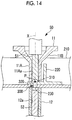
- Figs. 11 to 14 are longitudinal sectional views illustrating the caulking operation of the rivet 300 by the caulking unit 50.
- the supporting unit 10 is a device that supports the stringer 210 and the clip 220 so as to sandwich the stringer 210 and the clip 220 at the riveting position P (refer to Fig. 5 and the like).
- the supporting unit 10 has a moving mechanism (not illustrated) capable of moving to a position coaxial with an axis X in a vertical direction that passes through the riveting position P, and retreating onto an axis different from the axis X. As illustrated in Figs. 5 and 6 , the supporting unit 10 has an upper support body (first support body) 11 and a lower support body (second support body) 12 that are coaxially disposed on the axis X.
- the upper support body 11 includes a rod-shaped part 11A that has a through hole 11Aa extending along the axis X and is formed in a rod shape, and a diameter-reduced part 11B that is coupled to the rod-shaped part 11A and is reduced in an external diameter and an internal diameter as approaching a coupling position with the rod-shaped part 11A, and is a member that supports an upper surface of the clip 220 at the riveting position P.
- the reason that the diameter-reduced part 11B has a shape that is reduced in the external diameter and the internal diameter as the diameter-reduced part 11B approaches the coupling position is to prevent any interference with a bearing part of the drilling unit 20 or the caulking unit 50.
- the lower support body 12 is formed in a rod shape having a through hole 12a extending along the axis X, and is a member that supports a lower surface of the stringer 210 at the riveting position P.
- the drilling unit 20 is a device that performs drilling of through holes 230 in the stringer 210 and the clip 220 at the riveting position P.
- the drilling unit 20 has a drill 21 that has blades formed at the tip and an outer peripheral surface thereof, and a body part 22 in which a drive part (not illustrated) for rotating the drill 21 around the axis X and moving the drill 21 along the axis X is built.
- the drilling unit 20 has a moving mechanism (not illustrated) capable of moving to a position coaxial with the axis X in the vertical direction that passes through the riveting position P, and retreating onto an axis different from the axis X.
- the rivet supply unit 30 is a device that supplies the rivet 300 that is suctioned by the rivet suction unit 40 and is inserted into the through holes 230 at the riveting position P.
- the rivet supply unit 30 selectively supplies a rivet 300 to be inserted to the riveting position P from various types of rivets 300 in accordance with an instruction from the control unit 60.
- the rivet suction unit 40 is a device that is formed in a cylindrical shape extending along the axis X, and suctions a head part 310 with the interior thereof being in a negative-pressure state in a state where one end thereof is brought into contact with the head part 310 of the rivet 300.
- the rivet suction unit 40 conveys the rivet 300 in a state where the head part 310 is suctioned, and inserts a shaft part 320 of the rivet 300 into the through holes 230 at the riveting position P.
- the rivet suction unit 40 includes a suction shaft 41 that is formed in a cylindrical shape extending along the axis X and opens on a tip side thereof, and a cylinder 42 to which a proximal end side of the suction shaft 41 is attached and in which a drive mechanism (not illustrated) for moving the suction shaft 41 forward and backward along the axis X is built.
- the rivet suction unit 40 has a moving mechanism (not illustrated) capable of moving to a position coaxial with the axis X in the vertical direction that passes through the riveting position P, and retreating onto an axis different from the axis X.
- the caulking unit 50 is a device that inserts a shaft-like upper anvil (caulking member) 51 and a shaft-like lower anvil (caulking member) 52 into the upper support body 11 and the lower support body 12 in a state where the shaft part 320 of the rivet 300 is inserted into the through holes 230, and brings the upper and lower anvils 51 and 52 close to each other to caulk the stringer 210 and the clip 220.
- the caulking unit 50 has a moving mechanism (not illustrated) capable of moving to a position coaxial with an axis X in a vertical direction that passes through the riveting position P, and retreating onto an axis different from axis X.
- the control unit 100 is a device that controls the supporting unit 10, the drilling unit 20, the rivet supply unit 30, the rivet suction unit 40, the caulking unit 50, and the control unit 60.
- the control unit 60 is constituted of, for example, a central processing unit (CPU), a random access memory (RAM), a read only memory (ROM), a computer-readable storage medium, and the like.
- CPU central processing unit
- RAM random access memory
- ROM read only memory
- a series of processing for realizing various functions are stored in the storage medium or the like in the form of a program as an example, and the various functions are realized when the CPU reads this program to the RAM or the like to execute processing of information and calculation processing.
- a form in which this program is installed in advance in the ROM or other storage media, a form in which this program is provided after being stored in the computer-readable storage medium, a form in which this program is distributed through communication means in a wired or wireless manner, or the like may be applied.
- the computer-readable storage medium is a magnetic disk, a magnetic-optical disk, a CD-ROM, a DVD-ROM, a semiconductor memory, or the like.
- Step S301 the control unit 60 controls the moving mechanism (not illustrated) such that the supporting unit 10 moves to the position coaxial with the axis X in the vertical direction that passes through the riveting position P, and retreating onto the axis different from the axis X. If the movement of the supporting unit 10 by Step S301 is completed, a state illustrated in Fig. 5 is brought about.
- Step S302 the control unit 60 moves the upper support body 11 and the lower support body 12 along the axis X so as to approach each other, and brings about a state where the upper support body 11 supports the upper surface of the clip 220 at the riveting position P and the lower support body 12 supports the lower surface of the stringer 210 at the riveting position P. If the supporting operation by Step S302 is completed, a state illustrated in Fig. 6 is brought about. The state where the supporting unit 10 supports the stringer 210 and the clip 220 at the riveting position P is held up to Step S312 to be described below.
- Step S303 the control unit 60 controls the moving mechanism (not illustrated) such that the drilling unit 20 moves to the position coaxial with the axis X in the vertical direction that passes through the riveting position P, and retreating onto the axis different from the axis X. If the movement of the drilling unit 20 by Step S303 is completed, a state illustrated in Fig. 7 is brought about.
- Step S304 the control unit 60 moves the drilling unit 20 downward along the axis X to strike the tip of the drill 21 against the riveting position P to execute the drilling operation. If the drilling operation by Step S303 is completed, a state illustrated in Fig. 8 is brought about, and the through holes 230 passing through the stringer 210 and the clip 220 is formed.
- Step S305 the control unit 60 moves the drilling unit 20 upward along axis X, and controls the moving mechanism (not illustrated) so as to further retreat to a retreat position on another axis different from the axis X in the vertical direction that passes through the riveting position P.
- Step S306 the control unit 60 controls the moving mechanism (not illustrated) such that the rivet suction unit 40 moves to the position coaxial with the axis X in the vertical direction that passes through the riveting position P, and retreating onto the axis different from the axis X. If the movement of the rivet suction unit 40 by Step S306 is completed, a state illustrated in Fig. 9 is brought about.
- the rivet suction unit 40 brings the head part 310 of the rivet 300 into contact with the tip of the cylindrical suction shaft 41 to bring the interior of the suction shaft 41 into a negative-pressure state, thereby suctioning the rivet 300.
- Step S307 the control unit 60 executes the insertion operation of causing the suction shaft 41 to project downward along the axis X from the cylinder 42 to insert the tip of the shaft part 320 of the rivet 300 into the through holes 230 in a state where the rivet 300 is suctioned. If the insertion operation of the rivet 300 by Step S307 is completed, a state illustrated in Fig. 10 is brought about.
- Step S308 the control unit 60 moves the rivet suction unit 40 upward along axis X, and controls the moving mechanism (not illustrated) so as to further retreat to a retreat position on another axis different from the axis X in the vertical direction that passes through the riveting position P.
- Step S309 the control unit 60 controls the moving mechanism (not illustrated) such that the caulking unit 50 moves to the position coaxial with the axis X in the vertical direction that passes through the riveting position P, and retreating onto the axis different from the axis X.
- the upper anvil 51 of the caulking unit 50 is moved downward along the axis X, and brings about a state where a tip part of the upper anvil 51 is butted against the head part 310 of the rivet 300. If the movement of the caulking unit 50 by Step S309 is completed, a state illustrated in Fig. 11 is brought about.
- Step S310 the control unit 60 controls the caulking unit 50 so as to execute the caulking operation.
- the control unit 60 further moves the upper anvil 51 of the caulking unit 50 downward along the axis X, and brings about a state where a lower surface of the head part 310 of the rivet 300 and the upper surface of the clip 220 are in contact with each other.
- the upper anvil 51 holds the position of the head part 310 of the rivet 300 on the axis X such that the lower surface of the head part 310 of the rivet 300 is not separated from the upper surface of the clip 220 at a caulking operation to be described below.
- control unit 60 moves the lower anvil 52 of the caulking unit 50 upward along the axis X, and brings about a state where a tip part of the lower anvil 52 is butted against the tip of the shaft part 320 of the rivet 300.
- the control unit 60 further moves the lower anvil 52 upward along the axis X, and plastically deforms the shaft part 320 of the rivet 300 made of a metal (for example, made of an aluminum alloy), to form the shaft part 320 in a shape larger than the internal diameter of the through holes 230.
- a metal for example, made of an aluminum alloy
- Step S311 the control unit 60 moves the upper anvil 51 upward along the axis X, moves the lower anvil 52 downward along the axis X, and controls the moving mechanism (not illustrated) so as to further retreat to a retreat position on another axis different from the axis X in the vertical direction that passes through the riveting position P.
- Step S312 since the caulking operation by the caulking unit 50 is completed and the stringer 210 and the clip 220 were fastened to each other by the rivet 300 at the riveting position P, in the control unit 60, releases the support by the supporting unit 10 to retreat the supporting unit 10. Specifically, the control unit 60 moves the upper support body 11 and the lower support body 12 along the axis X so as to be separated from each other. Moreover, the control unit 60 controls the moving mechanism (not illustrated) such that the supporting unit 10 retreats to a retreat position on another axis different from the axis X in the vertical direction that passes through the riveting position P.
- Step S313 since the fastening operation (drilling operation, insertion operation, and caulking operation) of one rivet 300 by Step S301 to Step S312 is completed, the control unit 60 determines whether or not the riveting of the rivet 300 is terminated.
- control unit 60 determines NO to repeat the processing of Step S301 to Step S312 again for the other rivets 300. On the other hand, in a case where the fastening operation of other rivets 300 are not performed, the control unit 60 determines YES to end the processing of this flowchart.
- a discharge hole 11a and a discharge hole 11b for discharging cutting chips to the outside are provided in an outer peripheral surface on a lower end side of the upper support body 11.
- the upper support body 11 is capable of generating the cutting chips generated therein from the discharge hole 11a and the discharge hole 11b to the outside.
- suction parts 410 and 420 are respectively brought close to outer peripheral surfaces of the discharge holes 11a and 11b, and the cutting chips are guided into the interiors of the suction parts 410 and 420 due to the action of the negative pressure generated inside the suction parts 410 and 420.
- the discharge hole 11a and the discharge hole 11b are provided in the upper support body 11
- a gap may be provided between the drill and through hole 11Aa to discharge the cutting chips from the diameter-reduced part 11B of the upper support body 11.
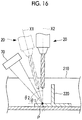
- the detecting device 70 is a device that detects a normal direction at the riveting position P.
- the detecting device 70 is a device that detects the axis direction of each unit (the drilling unit 20 in the example illustrated in Fig. 16 ) of the automatic riveting machine 100 with respect to the upper surface of the clip 220 at the riveting position P.
- the detecting device 70 detects the angle of an axis X1 of the drilling unit 20 with respect to the upper surface of the clip 220 as an angle ⁇ 1.
- the angle ⁇ 1 illustrated in Fig. 16 does not coincide with an angle ⁇ 2 (90 degrees) that is the angle of a normal line (axis X2) of the upper surface of the clip 220.
- control unit 60 controls the moving mechanism of the drilling unit 20 on the basis of the angle ⁇ 1 detected by the detecting device 70 such that the axis X1 of the drilling unit 20 coincides with the normal line (axis X2) of the upper surface of the clip 220. Accordingly, the drilling unit 20 moves to a indicated by a solid line in Fig. 16 , and the axis X1 of the drilling unit 20 coincides with the axis X2 that is the normal line. In this way, it is possible to perform the drilling operation by the drilling unit 20 from the normal direction of the upper surface of the clip 220, and form through holes in the normal direction.
- the drilling unit 20 is moved to the position in the normal direction.
- the supporting unit 10, the rivet suction unit 40, and the caulking unit 50 may be moved at positions in the normal direction on the basis of an angle detected by the detecting device 70.
- the rivet suction unit 40 of the present embodiment separates the shaft part 320 after the shaft part 320 of the rivet 300 is inserted into the through holes 230.
- the rivet suction unit 40 has a single seated sensor (not illustrated) that detects that the distance L from the cylinder 42 to the tip of the suction shaft 41 is constant.
- the rivet suction unit 40 having the single seated sensor can detect only that the distance L from the cylinder 42 to the tip of the suction shaft 41 is constant.
- the position or the like of the tip of the shaft part of the rivet with respect to the through holes 230 varies depending on the types of rivets to be suctioned by the rivet suction unit 40.
- the rivet 300 indicated by a solid line in Fig. 17 and a rivet 300A indicated by a dashed line have different shapes.
- a lower end of a shaft part 320A of the rivet 300A is disposed below a lower end of the shaft part 320 of the rivet 300.
- a lower end of a head part 310A of the rivet 300A is disposed below a lower end of the head part 310 of the rivet 300.
- positions where various types of rivets are separated from the rivet suction unit 40 can be appropriately set only using a single seated sensor by appropriately setting the distance L from the cylinder 42 to the tip of the suction shaft 41.
- a recess 51a is formed in a surface on a lower end side of the upper anvil 51.
- a bottom surface of the recess 51a has a planar shape. Meanwhile, the rivet 300 held by the recess 51a has a gentle convex surface shape in which an upper surface of the head part 310 is in contact with the bottom surface of the recess 51a.
- the bottom surface of the recess 51a is also capable of being in contact with an upper surface of the head part 310A of the rivet 300A.
- the head part 310A of the rivet 300A has a diameter smaller than the head part 310 of the rivet 300.
- the recess 51a has a shape capable of corresponding to both of the rivet 300 and the rivet 300A having the different shapes.
- the upper anvil 51 included in the caulking unit 50 of the present embodiment has a shape capable of executing the caulking operation of the various types of rivets.
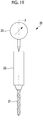
- the drilling unit 20 of the automatic riveting machine 100 of the present embodiment may further include a measuring instrument 23 that measures the amount of displacement (a maximum value of a push-back amount) caused by the reaction force received from the stringer 210 and the clip 220 and directed to above the axis X when the drilling unit 20 performs drilling.
- a measuring instrument 23 measures the amount of displacement (a maximum value of a push-back amount) caused by the reaction force received from the stringer 210 and the clip 220 and directed to above the axis X when the drilling unit 20 performs drilling.
- the measuring instrument 23 illustrated in Fig. 19 measures the amount of displacement caused by the reaction force (the maximum value of the push-back amount) applied to the drilling unit 20 during the drilling operation by the drilling unit 20, and transmits the amount of displacement to the control unit 60.
- the amount of displacement maximum value of the push-back amount
- the quality of the through holes 230 formed by the drilling operation becomes low. This is because the possibility that an error occur in the shape or the like of the through holes 230 due to the large reaction force is high.
- the control unit 60 stores the amount of displacement (push-back amount) measured by the measuring instrument 23 measures and the through holes 230 for which the amount of displacement is obtained, in association with each other. In this way, in a case where inspection or the like of a fastening state in the riveting position P is performed, a point having a possibility that the quality of the through holes 230 is low can be specified.
- the clip 220 out of the stringer 210 and the clip 220 of which the relative positions are fixed is supported at the riveting position P by the upper support body 11, and the stringer 210 is supported at the riveting position P by the lower support body 12.
- the upper support body 11 is formed in a rod shape having the through hole 11Aa extending along the axis X, the rivet 300 suctioned to the rivet suction unit 40 formed in a cylindrical shape is inserted, and the upper anvil 51 is inserted.
- the upper support body 11 is formed in a rod shape having the through hole 11Aa extending along the axis X, the upper support body 11 can be appropriately moved to the riveting position P even if the riveting position P is a narrow space.
- the rivet suction unit 40 can be formed in a shape suitable for the suction of the rivet 300, and the upper anvil 51 can be formed in a shape suitable for caulking.
- the rivet suction unit 40 having shapes capable of suctioning various types of rivets, respectively can be adopted, and the upper anvil 51 having shapes capable of caulking the various types of rivets, respectively, can be adopted.
- control unit 60 controls the drilling unit 20 so as to perform the drilling operation of the through holes 230 on the stringer 210 and the clip 220, and controls the rivet suction unit 40 so as to insert the shaft part 320 of the rivet 300 into the through holes 230 formed at the riveting position P after the drilling unit's 20 performs the drilling operation to retreat from the riveting position P.
- the discharge holes 11a and 11b for discharging the cutting chips generated by the drilling performed by the drilling unit 20 are formed in the upper support body 11. In this way, the cutting chips generated by the drilling operation performed by the drilling unit 20 can be suctioned from the discharge holes 11a and 11b and discharged to the outside, and the through holes 230 can be excellently finished.
- the automatic riveting machine 100 of the present embodiment a state where the members to be fastened (the stringer 210 and the clip 220) of which the relative positions are fixed by the upper support body 11 and the lower support body 12 are continuously supported without being separated from each other on the way. For that reason, since a series of operations from the drilling to the caulking of the rivet 300 can be completed in a state where the members to be fastened are continuously supported, the productivity is improved.
Landscapes
- Engineering & Computer Science (AREA)
- Mechanical Engineering (AREA)
- Insertion Pins And Rivets (AREA)
- Automatic Assembly (AREA)
Abstract
Description
- The present invention relates to a riveting machine and a control method for the same.
- In the related art, automatic riveting machines that automatically rivet a rivet in an object to be fastened, such as a fuselage panel of an aircraft, to fasten the object to be fastened have been known (for example, refer to Patent Document 1).
- In the riveting machine disclosed in
Patent Document 1, in order to perform riveting processing at a riveting point that is present in a narrow space, such as a corner portion of a member or an intersecting portion between members, a shaft body having an end surface that suctions the rivet is adopted instead of a gripping member that is operated to open and close. According toPatent Document 1, a transfer or loading of a rivet to a caulking position is performed by suction. Therefore, it is possible to make the support body for housing the shaft body compact, and to locate the support body comfortably also at a riveting point that is present in the narrow space, such as a corner portion of a member or an intersecting portion between members. - Patent Document 1: Japanese Patent No.
4379656 - However, in
Patent Document 1, the shaft body used for the transfer or loading of the rivet is also used as a member for caulking the rivet. For that reason, the shape of an end surface of the shaft body in contact with the head part of the rivet needs to be formed in a shape suitable for positioning when the rivet is caulked while the head part of the rivet is capable of being suctioned. - For that reason, in
Patent Document 1, it is necessary to cause the shape of the end surface of the shaft body to coincide with the shape of a specific rivet. In this case, in a case where riveting is performed using various types of rivets, it is necessary to perform riveting processing after various types of shaft bodies that coincide with the shapes of end surfaces of the various types of shaft bodies are prepared in advance, and substitution with a shaft body that coincides with the shape of a rivet to be used for riveting is made. - Hence, in
Patent Document 1, although it is possible to perform riveting in the narrow space, the productivity when the riveting is performed using the various types of rivets cannot be improved. - The invention has been made in view of such circumstances, and an object thereof is to provide a riveting machine and a control method for the same that improve productivity when performing riveting by using various types of rivets while making riveting of rivets possible in a narrow space.
- In order to solve the above subject, the invention adopts the following means.
- That is, a riveting machine of an aspect of the invention is a riveting machine that rivets a rivet at a riveting position of a pair of members to be fastened relative positions of which are fixed. The riveting machine includes a first support body that is formed in a rod shape having a through hole extending along an axis and supports one member of the pair of members to be fastened at the riveting position; a second support body that is formed in a rod shape having a through hole extending along the axis and supports the other pair of the pair of members to be fastened at the riveting position; a rivet suction part that is formed in a cylindrical shape extending along the axis, and suctions a head part of the rivet with an interior thereof being in a negative-pressure state in a state where one end is brought into contact with the head part of the rivet; a caulking part that caulks the pair of members to be fastened by the rivet by inserting a pair of caulking members into the first support body and the second support body and bringing the pair of caulking members close to each other, in a state where the rivet is inserted into through holes formed in the pair of members to be fastened at the riveting position; and a control unit that controls the rivet suction part and the caulking part. The control unit controls the rivet suction part so as to move the rivet suction part, to which the head part of the rivet is suctioned, to the first support body to insert the shaft part of the rivet into the through holes formed at the riveting position, and controls the caulking part so as to bring the pair of caulking members close to each other to caulk the pair of members to be fastened by the rivet after the rivet suction part inserts the rivet into the through holes and retreats from the riveting position.
- According to the riveting machine of the aspect of the invention, one member of the pair of the members to be fastened of which the relative positions are fixed is supported at the riveting position by the first support body, and the other member of the pair of the members to be fastened is supported at the riveting position by the second support body. The first support body is formed in a rod shape having a through hole extending along the axis, the rivet suctioned to the rivet suction part formed in a cylindrical shape is inserted, and one caulking member of the pair of caulking members is inserted.
- In this way, according to the riveting machine of the aspect of the invention, since the first support body is formed in a rod shape having the through hole extending along the axis, the first support body can be appropriately moved to the riveting position even if the riveting position is in a narrow space.
- According to the riveting machine of the aspect of the invention, in order to bring the pair of caulking members close to each other after the rivet is inserted into the through holes and the rivet suction part is retreated from the first support body, the insertion of the rivet and the caulking of the rivet can be performed as respectively independent operations. For that reason, the rivet suction part can be formed in a shape suitable for the suction of the rivet, and a caulking member can be formed in a shape suitable for caulking. For example, the rivet suction part having shapes capable of suctioning various types of rivets, respectively, can be adopted, and a caulking member having shapes capable of caulking the various types of rivets, respectively, can be adopted.
- Hence, compared to the case where insertion of a rivet and caulking of the rivet are performed using a single member, it is possible to perform riveting using various types of rivets, and the productivity when the riveting is performed is improved.
- In this way, according to the riveting machine of the aspect of the invention, it is possible to improve productivity when performing riveting by using various types of rivets while making riveting of rivets possible in a narrow space.
- The riveting machine of the aspect of the invention may further include a drilling part that performs drilling of the through holes in the pair of members to be fastened at the riveting position. The control unit may control the drilling part so as to perform the drilling of the through holes in the pair of members to be fastened that is supported at the riveting position by the first support body and the second support body, and may control the rivet suction part so as to insert the shaft part of the rivet into the through holes formed at the riveting position after the drilling part performs the drilling of the through holes and retreats from the riveting position.
- In this way, since it is not necessary to form the through holes in advance with another device with respect to the riveting position of the pair of members to be fastened, the productivity is improved.
- In the above configuration, a discharge hole for discharging cutting chips of the pair of members to be fastened which is generated by the drilling performed by the drilling part may be formed in the first support body.
- In this way, the cutting chips generated by the drilling performed by the drilling part can be suctioned from the discharge hole and discharged to the outside, and the through holes can be excellently finished.
- In the above configuration, the drilling part may include a measuring instrument that measures an amount of displacement caused by a reaction force received from the members to be fastened when performing the drilling of the through hole, and the control unit may store the amount of displacement measured by the measuring instrument and the through holes for which the amount of displacement is obtained, in association with each other.
- In this way, in a case where inspection or the like of a fastening state in the riveting position is performed, a point having a possibility that the quality of the through holes is low can be specified.
- A control method for a riveting machine of another aspect of the invention is a control method for a riveting machine that rivets a rivet at a riveting position of a pair of members to be fastened relative positions of which are fixed. The riveting machine includes a first support body that is formed in a rod shape having a through hole extending along an axis and supports one member of the pair of members to be fastened at the riveting position, a second support body that is formed in a rod shape having a through hole extending along the axis and supports the other member of the pair of members to be fastened at the riveting position, a rivet suction part that is formed in a cylindrical shape extending along the axis, and suctions a head part of the rivet with an interior thereof being in a negative-pressure state in a state where one end is brought into contact with the head part of the rivet, and a caulking part that caulks the pair of members to be fastened by the rivet by inserting a pair of caulking members into the first support body and the second support body and bringing the pair of caulking members close to each other, in a state where the rivet is inserted into through holes formed in the pair of members to be fastened at the riveting position. The method includes a first control step of controlling the rivet suction part so as to move the rivet suction part, to which the head part of the rivet is suctioned, to the first support body to insert the shaft part of the rivet into the through holes formed at the riveting position; and a second control step of controlling the caulking part so as to bring the pair of caulking members close to each other to caulk the pair of members to be fastened by the rivet after the rivet suction part inserts the rivet into the through holes and retreats from the riveting position.
- According to the control method for a riveting machine of the other aspect of the invention, in order to bring the pair of caulking members close to each other after the rivet is inserted into the through holes and the rivet suction part is retreated from the first support body, the insertion of the rivet and the caulking of the rivet can be performed as respectively independent operations. For that reason, the rivet suction part can be formed in a shape suitable for the suction of the rivet, and the caulking members can be formed in a shape suitable for caulking. For example, the rivet suction part having shapes capable of suctioning various types of rivets, respectively, can be adopted, and a caulking member having shapes capable of caulking the various types of rivets, respectively, can be adopted.
- Hence, compared to the case where insertion of a rivet and caulking of the rivet are performed using a single member, it is possible to perform riveting using various types of rivets, and the productivity when the riveting is performed is improved.
- According to the invention, it is possible to provide the riveting machine and the control method for the same that improve the productivity when performing riveting by using various types of rivets while making riveting of rivets possible in a narrow space.
-
-
Fig. 1 is a configuration view illustrating a schematic configuration of an automatic riveting machine of an embodiment of the invention. -
Fig. 2 is a perspective view illustrating a stringer and a clip. -
Fig. 3 is a flowchart illustrating the processing to be executed by a control unit illustrated inFig. 1 . -
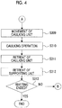
Fig. 4 is a flowchart illustrating the processing to be executed by the control unit illustrated inFig. 1 . -
Fig. 5 is a longitudinal sectional view illustrating a state where a supporting unit has retreated from the stringer and the clip. -
Fig. 6 is a longitudinal sectional view illustrating a state where the stringer and the clip are supported by the supporting unit. -
Fig. 7 is a longitudinal sectional view illustrating the stringer and the clip before a drilling operation by a drilling unit. -
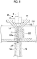
Fig. 8 is a longitudinal sectional view illustrating the stringer and the clip during the drilling operation by the drilling unit. -
Fig. 9 is a longitudinal sectional view illustrating the stringer and the clip before insertion of rivet by a rivet suction unit. -
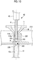
Fig. 10 is a longitudinal sectional view illustrating the stringer and the clip during the insertion of the rivet by the rivet suction unit. -
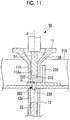
Fig. 11 is a longitudinal sectional view illustrating the stringer and the clip before a caulking operation by a caulking unit. -
Fig. 12 is a longitudinal sectional view illustrating the stringer and the clip during a pushing operation of the rivet by the caulking unit. -
Fig. 13 is a longitudinal sectional view illustrating the stringer and the clip before the caulking operation by the caulking unit. -
Fig. 14 is a longitudinal sectional view illustrating the stringer and the clip after the caulking operation by the caulking unit. -
Fig. 15 is a longitudinal sectional view illustrating a modification example of an upper support body of the supporting unit. -
Fig. 16 is a longitudinal sectional view illustrating a detecting device that detects a normal direction of a riveting position of the stringer and the clip. -
Fig. 17 is a longitudinal sectional view illustrating a position where the rivet suction unit separates the rivet. -
Fig. 18 is a longitudinal sectional view illustrating the shape of a lower end surface of an upper anvil of the caulking unit. -
Fig. 19 is a front view illustrating a measuring instrument that measures a reaction force that the drilling unit receives when drilling is performed. Description of Embodiments - Hereinafter, an automatic
riveting machine 100 of an embodiment of the invention will be described with reference to the drawings. - The automatic
riveting machine 100 of the present embodiment is a machine that rivets arivet 300 to a riveting position P (refer toFig. 5 and the like) of each of a pair of members to be fastened including a stringer 210 (longitudinal penetrating member) and aclip 220 that are illustrated inFig. 2 . - The
stringer 210 is an elongated member that is disposed at intervals in an axis direction of an aircraft. Theclip 220 is a member for fastening thestringer 210 to a frame (not illustrated) that holds a body of the aircraft split into panels in a cylindrical shape. Thestringer 210 and theclip 220 are formed of, for example, an aluminum alloy. - As illustrated in
Fig. 2 , thestringer 210 and theclip 220 are fastened to each other by, for example therivet 300 formed of an aluminum alloy. Although only asingle clip 220 is illustrated inFig. 2 , a plurality of theclips 220 are fastened to thestringer 210 at a plurality of points in a length direction thereof by the automaticriveting machine 100. - Relative positions of the
stringer 210 and theclip 220 are fixed by a gripping device (not illustrated), such as a robot hand, a fixture for temporary stop, or the like until thestringer 210 and theclip 220 are fastened to each other by the automaticriveting machine 100. - As illustrated in the schematic configuration of
Fig. 1 , the automaticriveting machine 100 includes a supportingunit 10, adrilling unit 20, arivet supply unit 30, arivet suction unit 40, acaulking unit 50, and acontrol unit 60. As illustrated inFig. 1 , thecontrol unit 60 and the other respective parts are electrically connected to each other so as to be capable of communicating with each other via signal lines. - In the present embodiment,
Figs. 3 and4 are flowcharts illustrating the processing to be executed by thecontrol unit 60.Figs. 5 and6 are longitudinal sectional views illustrating the operation of supporting thestringer 210 and theclip 220 by the supportingunit 10.Figs. 7 and8 are longitudinal sectional views illustrating the drilling operation of thestringer 210 and theclip 220 by thedrilling unit 20.Figs. 9 and10 are longitudinal sectional views illustrating the insertion operation of therivet 300 by therivet suction unit 40.Figs. 11 to 14 are longitudinal sectional views illustrating the caulking operation of therivet 300 by thecaulking unit 50. - Hereinafter, the respective parts included in the automatic
riveting machine 100 will be described. - The supporting
unit 10 is a device that supports thestringer 210 and theclip 220 so as to sandwich thestringer 210 and theclip 220 at the riveting position P (refer toFig. 5 and the like). - The supporting
unit 10 has a moving mechanism (not illustrated) capable of moving to a position coaxial with an axis X in a vertical direction that passes through the riveting position P, and retreating onto an axis different from the axis X. As illustrated inFigs. 5 and6 , the supportingunit 10 has an upper support body (first support body) 11 and a lower support body (second support body) 12 that are coaxially disposed on the axis X. - As illustrated in
Fig. 5 , theupper support body 11 includes a rod-shapedpart 11A that has a through hole 11Aa extending along the axis X and is formed in a rod shape, and a diameter-reducedpart 11B that is coupled to the rod-shapedpart 11A and is reduced in an external diameter and an internal diameter as approaching a coupling position with the rod-shapedpart 11A, and is a member that supports an upper surface of theclip 220 at the riveting position P. - The reason that the diameter-reduced
part 11B has a shape that is reduced in the external diameter and the internal diameter as the diameter-reducedpart 11B approaches the coupling position is to prevent any interference with a bearing part of thedrilling unit 20 or thecaulking unit 50. - The
lower support body 12 is formed in a rod shape having a throughhole 12a extending along the axis X, and is a member that supports a lower surface of thestringer 210 at the riveting position P. - The
drilling unit 20 is a device that performs drilling of throughholes 230 in thestringer 210 and theclip 220 at the riveting position P. - As illustrated in
Figs. 7 and8 , thedrilling unit 20 has adrill 21 that has blades formed at the tip and an outer peripheral surface thereof, and abody part 22 in which a drive part (not illustrated) for rotating thedrill 21 around the axis X and moving thedrill 21 along the axis X is built. Thedrilling unit 20 has a moving mechanism (not illustrated) capable of moving to a position coaxial with the axis X in the vertical direction that passes through the riveting position P, and retreating onto an axis different from the axis X. - The
rivet supply unit 30 is a device that supplies therivet 300 that is suctioned by therivet suction unit 40 and is inserted into the throughholes 230 at the riveting position P. Therivet supply unit 30 selectively supplies arivet 300 to be inserted to the riveting position P from various types ofrivets 300 in accordance with an instruction from thecontrol unit 60. - As illustrated in
Figs. 9 and10 , therivet suction unit 40 is a device that is formed in a cylindrical shape extending along the axis X, and suctions ahead part 310 with the interior thereof being in a negative-pressure state in a state where one end thereof is brought into contact with thehead part 310 of therivet 300. Therivet suction unit 40 conveys therivet 300 in a state where thehead part 310 is suctioned, and inserts ashaft part 320 of therivet 300 into the throughholes 230 at the riveting position P. - As illustrated in
Figs. 9 and10 , therivet suction unit 40 includes asuction shaft 41 that is formed in a cylindrical shape extending along the axis X and opens on a tip side thereof, and acylinder 42 to which a proximal end side of thesuction shaft 41 is attached and in which a drive mechanism (not illustrated) for moving thesuction shaft 41 forward and backward along the axis X is built. Therivet suction unit 40 has a moving mechanism (not illustrated) capable of moving to a position coaxial with the axis X in the vertical direction that passes through the riveting position P, and retreating onto an axis different from the axis X. - The
caulking unit 50 is a device that inserts a shaft-like upper anvil (caulking member) 51 and a shaft-like lower anvil (caulking member) 52 into theupper support body 11 and thelower support body 12 in a state where theshaft part 320 of therivet 300 is inserted into the throughholes 230, and brings the upper andlower anvils stringer 210 and theclip 220. Thecaulking unit 50 has a moving mechanism (not illustrated) capable of moving to a position coaxial with an axis X in a vertical direction that passes through the riveting position P, and retreating onto an axis different from axis X. - The
control unit 100 is a device that controls the supportingunit 10, thedrilling unit 20, therivet supply unit 30, therivet suction unit 40, thecaulking unit 50, and thecontrol unit 60. - The
control unit 60 is constituted of, for example, a central processing unit (CPU), a random access memory (RAM), a read only memory (ROM), a computer-readable storage medium, and the like. A series of processing for realizing various functions are stored in the storage medium or the like in the form of a program as an example, and the various functions are realized when the CPU reads this program to the RAM or the like to execute processing of information and calculation processing. A form in which this program is installed in advance in the ROM or other storage media, a form in which this program is provided after being stored in the computer-readable storage medium, a form in which this program is distributed through communication means in a wired or wireless manner, or the like may be applied. The computer-readable storage medium is a magnetic disk, a magnetic-optical disk, a CD-ROM, a DVD-ROM, a semiconductor memory, or the like. - Next, the processing to be executed by the
control unit 60 of the present embodiment will be described with reference toFigs. 3 and4 . - In Step S301, the
control unit 60 controls the moving mechanism (not illustrated) such that the supportingunit 10 moves to the position coaxial with the axis X in the vertical direction that passes through the riveting position P, and retreating onto the axis different from the axis X. If the movement of the supportingunit 10 by Step S301 is completed, a state illustrated inFig. 5 is brought about. - In Step S302, the
control unit 60 moves theupper support body 11 and thelower support body 12 along the axis X so as to approach each other, and brings about a state where theupper support body 11 supports the upper surface of theclip 220 at the riveting position P and thelower support body 12 supports the lower surface of thestringer 210 at the riveting position P. If the supporting operation by Step S302 is completed, a state illustrated inFig. 6 is brought about. The state where the supportingunit 10 supports thestringer 210 and theclip 220 at the riveting position P is held up to Step S312 to be described below. - In Step S303, the
control unit 60 controls the moving mechanism (not illustrated) such that thedrilling unit 20 moves to the position coaxial with the axis X in the vertical direction that passes through the riveting position P, and retreating onto the axis different from the axis X. If the movement of thedrilling unit 20 by Step S303 is completed, a state illustrated inFig. 7 is brought about. - In Step S304, the
control unit 60 moves thedrilling unit 20 downward along the axis X to strike the tip of thedrill 21 against the riveting position P to execute the drilling operation. If the drilling operation by Step S303 is completed, a state illustrated inFig. 8 is brought about, and the throughholes 230 passing through thestringer 210 and theclip 220 is formed. - In Step S305, the
control unit 60 moves thedrilling unit 20 upward along axis X, and controls the moving mechanism (not illustrated) so as to further retreat to a retreat position on another axis different from the axis X in the vertical direction that passes through the riveting position P. - In Step S306, the
control unit 60 controls the moving mechanism (not illustrated) such that therivet suction unit 40 moves to the position coaxial with the axis X in the vertical direction that passes through the riveting position P, and retreating onto the axis different from the axis X. If the movement of therivet suction unit 40 by Step S306 is completed, a state illustrated inFig. 9 is brought about. - As illustrated in
Fig. 9 , therivet suction unit 40 brings thehead part 310 of therivet 300 into contact with the tip of thecylindrical suction shaft 41 to bring the interior of thesuction shaft 41 into a negative-pressure state, thereby suctioning therivet 300. - In Step S307, the
control unit 60 executes the insertion operation of causing thesuction shaft 41 to project downward along the axis X from thecylinder 42 to insert the tip of theshaft part 320 of therivet 300 into the throughholes 230 in a state where therivet 300 is suctioned. If the insertion operation of therivet 300 by Step S307 is completed, a state illustrated inFig. 10 is brought about. - In Step S308, the
control unit 60 moves therivet suction unit 40 upward along axis X, and controls the moving mechanism (not illustrated) so as to further retreat to a retreat position on another axis different from the axis X in the vertical direction that passes through the riveting position P. - In Step S309, the
control unit 60 controls the moving mechanism (not illustrated) such that thecaulking unit 50 moves to the position coaxial with the axis X in the vertical direction that passes through the riveting position P, and retreating onto the axis different from the axis X. Theupper anvil 51 of thecaulking unit 50 is moved downward along the axis X, and brings about a state where a tip part of theupper anvil 51 is butted against thehead part 310 of therivet 300. If the movement of thecaulking unit 50 by Step S309 is completed, a state illustrated inFig. 11 is brought about. - In Step S310, the
control unit 60 controls thecaulking unit 50 so as to execute the caulking operation. - As illustrated in
Fig. 12 , thecontrol unit 60 further moves theupper anvil 51 of thecaulking unit 50 downward along the axis X, and brings about a state where a lower surface of thehead part 310 of therivet 300 and the upper surface of theclip 220 are in contact with each other. Theupper anvil 51 holds the position of thehead part 310 of therivet 300 on the axis X such that the lower surface of thehead part 310 of therivet 300 is not separated from the upper surface of theclip 220 at a caulking operation to be described below. - As illustrated in
Fig. 13 , thecontrol unit 60 moves thelower anvil 52 of thecaulking unit 50 upward along the axis X, and brings about a state where a tip part of thelower anvil 52 is butted against the tip of theshaft part 320 of therivet 300. - As illustrated in
Fig. 14 , thecontrol unit 60 further moves thelower anvil 52 upward along the axis X, and plastically deforms theshaft part 320 of therivet 300 made of a metal (for example, made of an aluminum alloy), to form theshaft part 320 in a shape larger than the internal diameter of the throughholes 230. - In Step S311, the
control unit 60 moves theupper anvil 51 upward along the axis X, moves thelower anvil 52 downward along the axis X, and controls the moving mechanism (not illustrated) so as to further retreat to a retreat position on another axis different from the axis X in the vertical direction that passes through the riveting position P. - In Step S312, since the caulking operation by the
caulking unit 50 is completed and thestringer 210 and theclip 220 were fastened to each other by therivet 300 at the riveting position P, in thecontrol unit 60, releases the support by the supportingunit 10 to retreat the supportingunit 10. Specifically, thecontrol unit 60 moves theupper support body 11 and thelower support body 12 along the axis X so as to be separated from each other. Moreover, thecontrol unit 60 controls the moving mechanism (not illustrated) such that the supportingunit 10 retreats to a retreat position on another axis different from the axis X in the vertical direction that passes through the riveting position P. - In Step S313, since the fastening operation (drilling operation, insertion operation, and caulking operation) of one
rivet 300 by Step S301 to Step S312 is completed, thecontrol unit 60 determines whether or not the riveting of therivet 300 is terminated. - In a case where the fastening operation of
other rivets 300 is performed, thecontrol unit 60 determines NO to repeat the processing of Step S301 to Step S312 again for theother rivets 300. On the other hand, in a case where the fastening operation ofother rivets 300 are not performed, thecontrol unit 60 determines YES to end the processing of this flowchart. - Here, the
upper support body 11 of the present embodiment will be described in more detail. - As illustrated in
Fig. 15 , adischarge hole 11a and adischarge hole 11b for discharging cutting chips to the outside are provided in an outer peripheral surface on a lower end side of theupper support body 11. - When the drilling operation of the
stringer 210 and theclip 220 is performed by thedrilling unit 20, theupper support body 11 is capable of generating the cutting chips generated therein from thedischarge hole 11a and thedischarge hole 11b to the outside. In order to discharge the cutting chips to the outside,suction parts suction parts suction parts - In the present embodiment, although an aspect in which the
discharge hole 11a and thedischarge hole 11b are provided in theupper support body 11 is adopted, it is also possible to adopt an aspect in which thedischarge hole 11a and thedischarge hole 11b are not provided in theupper support body 11. For example, in order to remove the generated cutting chips, a gap may be provided between the drill and through hole 11Aa to discharge the cutting chips from the diameter-reducedpart 11B of theupper support body 11. - Here, a detecting
device 70 included in the automaticriveting machine 100 of the present embodiment will be described. The detectingdevice 70 is a device that detects a normal direction at the riveting position P. The detectingdevice 70 is a device that detects the axis direction of each unit (thedrilling unit 20 in the example illustrated inFig. 16 ) of the automaticriveting machine 100 with respect to the upper surface of theclip 220 at the riveting position P. In an example illustrated inFig. 16 , in a case where thedrilling unit 20 is at a position indicated by a dashed line in the figure, the detectingdevice 70 detects the angle of an axis X1 of thedrilling unit 20 with respect to the upper surface of theclip 220 as an angle θ1. The angle θ1 illustrated inFig. 16 does not coincide with an angle θ2 (90 degrees) that is the angle of a normal line (axis X2) of the upper surface of theclip 220. - Thus, the
control unit 60 controls the moving mechanism of thedrilling unit 20 on the basis of the angle θ1 detected by the detectingdevice 70 such that the axis X1 of thedrilling unit 20 coincides with the normal line (axis X2) of the upper surface of theclip 220. Accordingly, thedrilling unit 20 moves to a indicated by a solid line inFig. 16 , and the axis X1 of thedrilling unit 20 coincides with the axis X2 that is the normal line. In this way, it is possible to perform the drilling operation by thedrilling unit 20 from the normal direction of the upper surface of theclip 220, and form through holes in the normal direction. - In the example illustrated in
Fig. 16 , thedrilling unit 20 is moved to the position in the normal direction. However, the supportingunit 10, therivet suction unit 40, and thecaulking unit 50 may be moved at positions in the normal direction on the basis of an angle detected by the detectingdevice 70. - The position where the
rivet suction unit 40 of the present embodiment separates therivet 300 will be described in detail. - In a case where a distance L from the
cylinder 42 to the tip of thesuction shaft 41 is constant, therivet suction unit 40 of the present embodiment separates theshaft part 320 after theshaft part 320 of therivet 300 is inserted into the throughholes 230. Therivet suction unit 40 has a single seated sensor (not illustrated) that detects that the distance L from thecylinder 42 to the tip of thesuction shaft 41 is constant. - The
rivet suction unit 40 having the single seated sensor can detect only that the distance L from thecylinder 42 to the tip of thesuction shaft 41 is constant. In this case, the position or the like of the tip of the shaft part of the rivet with respect to the throughholes 230 varies depending on the types of rivets to be suctioned by therivet suction unit 40. For example, therivet 300 indicated by a solid line inFig. 17 and arivet 300A indicated by a dashed line have different shapes. For that reason, a lower end of ashaft part 320A of therivet 300A is disposed below a lower end of theshaft part 320 of therivet 300. Similarly, a lower end of ahead part 310A of therivet 300A is disposed below a lower end of thehead part 310 of therivet 300. - For example, as in the
rivet 300 and therivet 300A illustrated inFig. 17 , in a case where various types of rivets are handled, it is optimal to provide a seated sensor that detects that a lower surface of a head part of each rivet is in contact with (seated on) the upper surface of theclip 220. However, in this case, a plurality of seated sensors for detecting a plurality of seating positions of various types of rivets are required. Meanwhile, since only a single seated sensor is sufficient in a modification example illustrated inFig. 17 , it is not necessary to provide the plurality of seated sensors. Even in a case where only a single seated sensor is used, positions where various types of rivets are separated from therivet suction unit 40 can be appropriately set only using a single seated sensor by appropriately setting the distance L from thecylinder 42 to the tip of thesuction shaft 41. - Next, the shape of the
upper anvil 51 included in thecaulking unit 50 of the present embodiment will be described in detail. As illustrated inFig. 18 , arecess 51a is formed in a surface on a lower end side of theupper anvil 51. - A bottom surface of the
recess 51a has a planar shape. Meanwhile, therivet 300 held by therecess 51a has a gentle convex surface shape in which an upper surface of thehead part 310 is in contact with the bottom surface of therecess 51a. - The bottom surface of the
recess 51a is also capable of being in contact with an upper surface of thehead part 310A of therivet 300A. Here, thehead part 310A of therivet 300A has a diameter smaller than thehead part 310 of therivet 300. In this way, therecess 51a has a shape capable of corresponding to both of therivet 300 and therivet 300A having the different shapes. In this way, theupper anvil 51 included in thecaulking unit 50 of the present embodiment has a shape capable of executing the caulking operation of the various types of rivets. - The
drilling unit 20 of the automaticriveting machine 100 of the present embodiment may further include a measuringinstrument 23 that measures the amount of displacement (a maximum value of a push-back amount) caused by the reaction force received from thestringer 210 and theclip 220 and directed to above the axis X when thedrilling unit 20 performs drilling. - The measuring
instrument 23 illustrated inFig. 19 measures the amount of displacement caused by the reaction force (the maximum value of the push-back amount) applied to thedrilling unit 20 during the drilling operation by thedrilling unit 20, and transmits the amount of displacement to thecontrol unit 60. In a case where the amount of displacement (maximum value of the push-back amount) is large, there is a possibility that the quality of the throughholes 230 formed by the drilling operation becomes low. This is because the possibility that an error occur in the shape or the like of the throughholes 230 due to the large reaction force is high. - In the automatic
riveting machine 100 of the present embodiment, thecontrol unit 60 stores the amount of displacement (push-back amount) measured by the measuringinstrument 23 measures and the throughholes 230 for which the amount of displacement is obtained, in association with each other. In this way, in a case where inspection or the like of a fastening state in the riveting position P is performed, a point having a possibility that the quality of the throughholes 230 is low can be specified. - The functions and the effects exhibited by the present embodiment described above will be described.
- According to the automatic
riveting machine 100 of the present embodiment, theclip 220 out of thestringer 210 and theclip 220 of which the relative positions are fixed is supported at the riveting position P by theupper support body 11, and thestringer 210 is supported at the riveting position P by thelower support body 12. Theupper support body 11 is formed in a rod shape having the through hole 11Aa extending along the axis X, therivet 300 suctioned to therivet suction unit 40 formed in a cylindrical shape is inserted, and theupper anvil 51 is inserted. - In this way, according to the automatic
riveting machine 100 of the present embodiment, since theupper support body 11 is formed in a rod shape having the through hole 11Aa extending along the axis X, theupper support body 11 can be appropriately moved to the riveting position P even if the riveting position P is a narrow space. - According to the automatic
riveting machine 100 of the present embodiment, in order to bring theupper anvil 51 and thelower anvil 52 close to each other after therivet 300 is inserted into the throughholes 230 and therivet suction unit 40 is retreated from theupper support body 11, the insertion of therivet 300 and the caulking of therivet 300 can be performed as respectively independent operations. For that reason, therivet suction unit 40 can be formed in a shape suitable for the suction of therivet 300, and theupper anvil 51 can be formed in a shape suitable for caulking. For example, therivet suction unit 40 having shapes capable of suctioning various types of rivets, respectively, can be adopted, and theupper anvil 51 having shapes capable of caulking the various types of rivets, respectively, can be adopted. - Hence, compared to the case where insertion of a rivet and caulking of the rivet are performed using a single member, it is possible to perform riveting using various types of rivets, and the productivity when the riveting is performed is improved.
- In the automatic
riveting machine 100 of the present embodiment, thecontrol unit 60 controls thedrilling unit 20 so as to perform the drilling operation of the throughholes 230 on thestringer 210 and theclip 220, and controls therivet suction unit 40 so as to insert theshaft part 320 of therivet 300 into the throughholes 230 formed at the riveting position P after the drilling unit's 20 performs the drilling operation to retreat from the riveting position P. - In this way, since it is not necessary to form the through
holes 230 in advance with another device with respect to the riveting position P of thestringer 210 and theclip 220, the productivity is improved. - The discharge holes 11a and 11b for discharging the cutting chips generated by the drilling performed by the
drilling unit 20 are formed in theupper support body 11. In this way, the cutting chips generated by the drilling operation performed by thedrilling unit 20 can be suctioned from the discharge holes 11a and 11b and discharged to the outside, and the throughholes 230 can be excellently finished. - In the automatic
riveting machine 100 of the present embodiment, a state where the members to be fastened (thestringer 210 and the clip 220) of which the relative positions are fixed by theupper support body 11 and thelower support body 12 are continuously supported without being separated from each other on the way. For that reason, since a series of operations from the drilling to the caulking of therivet 300 can be completed in a state where the members to be fastened are continuously supported, the productivity is improved. -
- 10:
- SUPPORTING UNIT
- 11:
- UPPER SUPPORT BODY (FIRST SUPPORT BODY)
- 11A:
- ROD-SHAPED PART
- 11Aa:
- THROUGH HOLE
- 11B:
- DIAMETER-REDUCED PART
- 11a:
- DISCHARGE HOLE
- 11b:
- DISCHARGE HOLE
- 12:
- LOWER SUPPORT BODY (SECOND SUPPORT BODY)
- 20:
- DRILLING UNIT (DRILLING PART)
- 21:
- DRILL
- 22:
- BODY PART
- 23:
- MEASURING INSTRUMENT
- 30:
- RIVET SUPPLY UNIT
- 40:
- RIVET SUCTION UNIT (RIVET SUCTION PART)
- 41:
- SUCTION SHAFT
- 42:
- CYLINDER
- 50:
- CAULKING UNIT (CAULKING PART)
- 51:
- UPPER ANVIL (CAULKING MEMBER)
- 51a:
- RECESS
- 52:
- LOWER ANVIL (CAULKING MEMBER)
- 60:
- CONTROL UNIT
- 70:
- DETECTING DEVICE
- 100:
- AUTOMATIC RIVETING MACHINE
- 210:
- STRINGER (LONGITUDINAL PENETRATING MEMBER)
- 220:
- CLIP
- 230:
- THROUGH HOLE
- 300:
- RIVET
- 310:
- HEAD PART
- 320:
- SHAFT PART
- 410, 420:
- SUCTION PART
- P:
- RIVETING POSITION
- X, X1, X2:
- AXIS
- θ1, θ2:
- ANGLE
Claims (5)
- A riveting machine that rivets a rivet at a riveting position of a pair of members to be fastened relative positions of which are fixed, the riveting machine comprising:a first support body that is formed in a rod shape having a through hole extending along an axis and supports one member of the pair of members to be fastened at the riveting position;a second support body that is formed in a rod shape having a through hole extending along the axis and supports the other member of the pair of members to be fastened at the riveting position;a rivet suction part that is formed in a cylindrical shape extending along the axis, and suctions a head part of the rivet with an interior thereof being in a negative-pressure state in a state where one end is brought into contact with the head part of the rivet;a caulking part that caulks the pair of members to be fastened by the rivet by inserting a pair of shaft-like caulking members into the first support body and the second support body and bringing the pair of caulking members close to each other, in a state where the rivet is inserted into through holes formed in the pair of members to be fastened at the riveting position; anda control unit that controls the rivet suction part and the caulking part,wherein the control unit controls the rivet suction part so as to move the rivet suction part, to which the head part of the rivet is suctioned, to the first support body to insert a shaft part of the rivet into the through holes formed at the riveting position, and controls the caulking part so as to bring the pair of caulking members close to each other to caulk the pair of members to be fastened by the rivet after the rivet suction part inserts the rivet into the through holes and retreats from the riveting position.
- The riveting machine according to Claim 1, further comprising:a drilling part that performs drilling of the through holes in the pair of members to be fastened at the riveting position,wherein the control unit controls the drilling part so as to perform the drilling of the through holes in the pair of members to be fastened that is supported at the riveting position by the first support body and the second support body, and controls the rivet suction part so as to insert the shaft part of the rivet into the through holes formed at the riveting position after the drilling part performs the drilling of the through holes and retreats from the riveting position.
- The riveting machine according to Claim 2,
wherein a discharge hole for discharging cutting chips of the pair of members to be fastened which is generated by the drilling performed by the drilling part is formed in the first support body. - The riveting machine according to Claim 2 or 3,
wherein the drilling part includes a measuring instrument that measures an amount of displacement caused by a reaction force received from the members to be fastened when performing the drilling of the through hole, and
wherein the control unit stores the amount of displacement measured by the measuring instrument and the through holes for which the amount of displacement is obtained, in association with each other. - A control method for a riveting machine that rivets a rivet at a riveting position of a pair of members to be fastened relative positions of which are fixed, the riveting machine including
a first support body that is formed in a rod shape having a through hole extending along an axis and supports one member of the pair of members to be fastened at the riveting position,
a second support body that is formed in a rod shape having a through hole extending along the axis and supports the other member of the pair of members to be fastened at the riveting position,
a rivet suction part that is formed in a cylindrical shape extending along the axis, and suctions a head part of the rivet with an interior thereof being in a negative-pressure state in a state where one end is brought into contact with the head part of the rivet, and
a caulking part that caulks the pair of members to be fastened by the rivet by inserting a pair of caulking members into the first support body and the second support body and bringing the pair of caulking members close to each other, in a state where the rivet is inserted into through holes formed in the pair of members to be fastened at the riveting position,
the method comprising:a first control step of controlling the rivet suction part so as to move the rivet suction part, to which the head part of the rivet is suctioned, to the first support body to insert a shaft part of the rivet into the through holes formed at the riveting position; anda second control step of controlling the caulking part so as to bring the pair of caulking members close to each other to caulk the pair of members to be fastened by the rivet after the rivet suction part inserts the rivet into the through holes and retreats from the riveting position.
Applications Claiming Priority (2)
| Application Number | Priority Date | Filing Date | Title |
|---|---|---|---|
| JP2016101942A JP2017205802A (en) | 2016-05-20 | 2016-05-20 | Riveting device and control method thereof |
| PCT/JP2017/018936 WO2017200104A1 (en) | 2016-05-20 | 2017-05-19 | Riveting machine and control method for same |
Publications (3)
| Publication Number | Publication Date |
|---|---|
| EP3437755A1 true EP3437755A1 (en) | 2019-02-06 |
| EP3437755A4 EP3437755A4 (en) | 2019-05-01 |
| EP3437755B1 EP3437755B1 (en) | 2020-04-01 |
Family
ID=60325449
Family Applications (1)
| Application Number | Title | Priority Date | Filing Date |
|---|---|---|---|
| EP17799528.9A Active EP3437755B1 (en) | 2016-05-20 | 2017-05-19 | Riveting machine and control method for same |
Country Status (5)
| Country | Link |
|---|---|
| US (1) | US10940525B2 (en) |
| EP (1) | EP3437755B1 (en) |
| JP (1) | JP2017205802A (en) |
| CN (1) | CN109070187A (en) |
| WO (1) | WO2017200104A1 (en) |
Cited By (1)
| Publication number | Priority date | Publication date | Assignee | Title |
|---|---|---|---|---|
| CN117564695A (en) * | 2023-12-12 | 2024-02-20 | 芜湖东光大华机械制造有限公司 | An automatic assembly equipment for automobile flywheel assembly |
Families Citing this family (10)
| Publication number | Priority date | Publication date | Assignee | Title |
|---|---|---|---|---|
| JP7191657B2 (en) | 2018-11-22 | 2022-12-19 | 三菱重工業株式会社 | Clamping method and clamping device |
| IT201800011097A1 (en) * | 2018-12-14 | 2020-06-14 | Cosberg Spa | RIVETING DEVICE FOR ASSEMBLY PLANTS |
| US11224951B2 (en) * | 2018-12-21 | 2022-01-18 | The Boeing Company | Method and apparatus for single-sided clamp-up |
| US11833592B2 (en) * | 2020-02-08 | 2023-12-05 | Jr Automation Technologies, Llc | Drill system, an upper drill tool and a lower drill tool for precision forming of openings in a bracket, and methods of use |
| JP2021191584A (en) | 2020-06-05 | 2021-12-16 | 三菱重工業株式会社 | Fastening device and fastening method |
| JP2022002857A (en) | 2020-06-23 | 2022-01-11 | 三菱重工業株式会社 | Crimping device and crimping method |
| JP7326360B2 (en) * | 2021-02-08 | 2023-08-15 | 三菱重工業株式会社 | Support unit and riveting device |
| GB2627511B (en) * | 2023-02-24 | 2025-05-07 | Airbus Operations Ltd | Self aligning system |
| CN117259658B (en) * | 2023-10-11 | 2024-06-14 | 南通中兴轴承有限公司 | Riveting device for automobile clutch release bearing and use method |
| CN118404346A (en) * | 2024-05-21 | 2024-07-30 | 西安兴航航空科技股份有限公司 | A gantry type automatic drilling and riveting machine |
Family Cites Families (19)
| Publication number | Priority date | Publication date | Assignee | Title |
|---|---|---|---|---|
| US4901431A (en) * | 1988-06-06 | 1990-02-20 | Textron Inc. | Powered fastener installation apparatus |
| JPH02244517A (en) * | 1989-03-17 | 1990-09-28 | Tanaka Kikinzoku Kogyo Kk | Method of transport and insertion of rivet type contact into recess in base |
| US4955119A (en) * | 1989-07-11 | 1990-09-11 | Imta | Multi-task end effector for robotic machining center |
| US4995148A (en) * | 1990-03-30 | 1991-02-26 | Imta | Robotically controlled multi-task end effector |
| JPH0483549U (en) * | 1990-11-30 | 1992-07-21 | ||
| US5213454A (en) * | 1990-12-21 | 1993-05-25 | The Boeing Company | Apparatus for chip vacuum, mist lubrication and coil cooling |
| JP2516366Y2 (en) * | 1991-05-22 | 1996-11-06 | プレス工業株式会社 | Rivet caulking device with rivet head detection mechanism |
| JPH0686838U (en) * | 1993-05-21 | 1994-12-20 | 弘之 石川 | Riveting machine |
| JP2980240B1 (en) | 1998-07-22 | 1999-11-22 | 西松建設株式会社 | Medium pressure detector |
| JP4379656B2 (en) * | 2000-03-23 | 2009-12-09 | 日本飛行機株式会社 | Crushing apparatus and crushing method |
| ATE292532T1 (en) | 2001-01-15 | 2005-04-15 | Newfrey Llc | METHOD FOR RIVETING OR PUNCHING AND DEVICE FOR CARRYING OUT THE METHOD |
| JP2003010941A (en) * | 2001-06-29 | 2003-01-15 | Japan Aircraft Mfg Co Ltd | Riveting device |
| CZ305122B6 (en) * | 2002-01-21 | 2015-05-13 | MS Gerätebau GmbH | Insertion tool and method of checking insertion processes for such a tool |
| JP3984066B2 (en) * | 2002-02-08 | 2007-09-26 | 川崎重工業株式会社 | Hole imaging device and processing device |
| CN201470805U (en) * | 2009-07-16 | 2010-05-19 | 郑州航天电子技术有限公司 | Riveting machine |
| US9021677B1 (en) | 2012-01-12 | 2015-05-05 | Gemcor Ii, Llc | Apparatus and method for improving safety and quality of automatic riveting operations |
| JP5851868B2 (en) | 2012-02-03 | 2016-02-03 | 三菱重工業株式会社 | Bar-shaped member chucking device and bar-shaped member chucking method |
| CN103567350A (en) * | 2012-07-30 | 2014-02-12 | 成都飞机工业(集团)有限责任公司 | Method for preventing automatic drilling and riveting machine from no-rivet riveting or crooked rivet riveting |
| CN104399859B (en) * | 2014-11-25 | 2016-07-06 | 眉山南车紧固件科技有限公司 | Thin plate self-locking is solidly connected method and system |
-
2016
- 2016-05-20 JP JP2016101942A patent/JP2017205802A/en active Pending
-
2017
- 2017-05-19 WO PCT/JP2017/018936 patent/WO2017200104A1/en not_active Ceased
- 2017-05-19 CN CN201780026955.6A patent/CN109070187A/en active Pending
- 2017-05-19 EP EP17799528.9A patent/EP3437755B1/en active Active
- 2017-05-19 US US16/097,637 patent/US10940525B2/en active Active
Cited By (1)
| Publication number | Priority date | Publication date | Assignee | Title |
|---|---|---|---|---|
| CN117564695A (en) * | 2023-12-12 | 2024-02-20 | 芜湖东光大华机械制造有限公司 | An automatic assembly equipment for automobile flywheel assembly |
Also Published As
| Publication number | Publication date |
|---|---|
| US10940525B2 (en) | 2021-03-09 |
| JP2017205802A (en) | 2017-11-24 |
| US20190134699A1 (en) | 2019-05-09 |
| WO2017200104A1 (en) | 2017-11-23 |
| CN109070187A (en) | 2018-12-21 |
| EP3437755A4 (en) | 2019-05-01 |
| EP3437755B1 (en) | 2020-04-01 |
Similar Documents
| Publication | Publication Date | Title |
|---|---|---|
| EP3437755B1 (en) | Riveting machine and control method for same | |
| US8407873B2 (en) | System for loading collars onto bolts in large-scale manufacturing operations | |
| EP2808110B1 (en) | Drilling apparatus and drilling method | |
| US6986450B2 (en) | Fastener insertion apparatus | |
| US6446330B2 (en) | Gripper systems for rivets and collars used in large-scale assembly operations | |
| US7559136B2 (en) | Press for attaching nuts to pipes | |
| US5329691A (en) | Hole probe apparatus | |
| US20100301568A1 (en) | Tool mounting device | |
| EP0388117B1 (en) | Method and apparatus for pull-through blind installation of a tubular member | |
| US8769789B2 (en) | Die for rivet machine | |
| US20080005885A1 (en) | Compensating unit for a tool unit and method for inserting an element into a workpiece | |
| US7387006B1 (en) | Sensing system for sheet metal forming tool | |
| US9789531B2 (en) | Fastener applying apparatus and fastener applying method | |
| US10919648B2 (en) | Method for manufacturing component and component manufacturing system | |
| US20130047425A1 (en) | Rivet setter | |
| JP2009297753A (en) | Piercing method using provisional tack | |
| CN208146851U (en) | Mold and fastening means for deforming material in fastening means | |
| CN107790604A (en) | Automobile trunk hinge automatic riveting machine | |
| EP4294594B1 (en) | Method for operating a machine for laser machining of tubes and profiled sections with an automatic system for the application of threaded inserts integrated in the machine | |
| CN210650733U (en) | Material taking paw for mechanical hand | |
| WO2017018107A1 (en) | Positioning system and positioning method | |
| WO2008069635A1 (en) | Foam plug inserting apparatus and foam flug inserting method | |
| JP2026000864A (en) | Fastener installation assembly, end effector tool, and method | |
| Zieve | Frame-Clip Riveting End Effector | |
| JPH05212631A (en) | Incorporating device |
Legal Events
| Date | Code | Title | Description |
|---|---|---|---|
| STAA | Information on the status of an ep patent application or granted ep patent |
Free format text: STATUS: THE INTERNATIONAL PUBLICATION HAS BEEN MADE |
|
| PUAI | Public reference made under article 153(3) epc to a published international application that has entered the european phase |
Free format text: ORIGINAL CODE: 0009012 |
|
| STAA | Information on the status of an ep patent application or granted ep patent |
Free format text: STATUS: REQUEST FOR EXAMINATION WAS MADE |
|
| 17P | Request for examination filed |
Effective date: 20181029 |
|
| AK | Designated contracting states |
Kind code of ref document: A1 Designated state(s): AL AT BE BG CH CY CZ DE DK EE ES FI FR GB GR HR HU IE IS IT LI LT LU LV MC MK MT NL NO PL PT RO RS SE SI SK SM TR |
|
| AX | Request for extension of the european patent |
Extension state: BA ME |
|
| A4 | Supplementary search report drawn up and despatched |
Effective date: 20190401 |
|
| RIC1 | Information provided on ipc code assigned before grant |
Ipc: B21J 15/28 20060101AFI20190326BHEP Ipc: B23P 19/04 20060101ALI20190326BHEP Ipc: B21J 15/32 20060101ALI20190326BHEP Ipc: B21J 15/48 20060101ALI20190326BHEP Ipc: B21J 15/10 20060101ALI20190326BHEP Ipc: B21J 15/02 20060101ALI20190326BHEP Ipc: B21J 15/30 20060101ALI20190326BHEP |
|
| DAV | Request for validation of the european patent (deleted) | ||
| DAX | Request for extension of the european patent (deleted) | ||
| GRAP | Despatch of communication of intention to grant a patent |
Free format text: ORIGINAL CODE: EPIDOSNIGR1 |
|
| STAA | Information on the status of an ep patent application or granted ep patent |
Free format text: STATUS: GRANT OF PATENT IS INTENDED |
|
| INTG | Intention to grant announced |
Effective date: 20191218 |
|
| GRAS | Grant fee paid |
Free format text: ORIGINAL CODE: EPIDOSNIGR3 |
|
| GRAA | (expected) grant |
Free format text: ORIGINAL CODE: 0009210 |
|
| STAA | Information on the status of an ep patent application or granted ep patent |
Free format text: STATUS: THE PATENT HAS BEEN GRANTED |
|
| AK | Designated contracting states |
Kind code of ref document: B1 Designated state(s): AL AT BE BG CH CY CZ DE DK EE ES FI FR GB GR HR HU IE IS IT LI LT LU LV MC MK MT NL NO PL PT RO RS SE SI SK SM TR |
|
| REG | Reference to a national code |
Ref country code: GB Ref legal event code: FG4D |
|
| REG | Reference to a national code |
Ref country code: CH Ref legal event code: EP Ref country code: AT Ref legal event code: REF Ref document number: 1250719 Country of ref document: AT Kind code of ref document: T Effective date: 20200415 |
|
| REG | Reference to a national code |
Ref country code: DE Ref legal event code: R096 Ref document number: 602017014135 Country of ref document: DE |
|
| REG | Reference to a national code |
Ref country code: IE Ref legal event code: FG4D |
|
| PG25 | Lapsed in a contracting state [announced via postgrant information from national office to epo] |
Ref country code: BG Free format text: LAPSE BECAUSE OF FAILURE TO SUBMIT A TRANSLATION OF THE DESCRIPTION OR TO PAY THE FEE WITHIN THE PRESCRIBED TIME-LIMIT Effective date: 20200701 |
|
| REG | Reference to a national code |
Ref country code: NL Ref legal event code: MP Effective date: 20200401 |
|
| REG | Reference to a national code |
Ref country code: LT Ref legal event code: MG4D |
|
| PG25 | Lapsed in a contracting state [announced via postgrant information from national office to epo] |
Ref country code: PT Free format text: LAPSE BECAUSE OF FAILURE TO SUBMIT A TRANSLATION OF THE DESCRIPTION OR TO PAY THE FEE WITHIN THE PRESCRIBED TIME-LIMIT Effective date: 20200817 Ref country code: LT Free format text: LAPSE BECAUSE OF FAILURE TO SUBMIT A TRANSLATION OF THE DESCRIPTION OR TO PAY THE FEE WITHIN THE PRESCRIBED TIME-LIMIT Effective date: 20200401 Ref country code: GR Free format text: LAPSE BECAUSE OF FAILURE TO SUBMIT A TRANSLATION OF THE DESCRIPTION OR TO PAY THE FEE WITHIN THE PRESCRIBED TIME-LIMIT Effective date: 20200702 Ref country code: NO Free format text: LAPSE BECAUSE OF FAILURE TO SUBMIT A TRANSLATION OF THE DESCRIPTION OR TO PAY THE FEE WITHIN THE PRESCRIBED TIME-LIMIT Effective date: 20200701 Ref country code: NL Free format text: LAPSE BECAUSE OF FAILURE TO SUBMIT A TRANSLATION OF THE DESCRIPTION OR TO PAY THE FEE WITHIN THE PRESCRIBED TIME-LIMIT Effective date: 20200401 Ref country code: CZ Free format text: LAPSE BECAUSE OF FAILURE TO SUBMIT A TRANSLATION OF THE DESCRIPTION OR TO PAY THE FEE WITHIN THE PRESCRIBED TIME-LIMIT Effective date: 20200401 Ref country code: IS Free format text: LAPSE BECAUSE OF FAILURE TO SUBMIT A TRANSLATION OF THE DESCRIPTION OR TO PAY THE FEE WITHIN THE PRESCRIBED TIME-LIMIT Effective date: 20200801 Ref country code: SE Free format text: LAPSE BECAUSE OF FAILURE TO SUBMIT A TRANSLATION OF THE DESCRIPTION OR TO PAY THE FEE WITHIN THE PRESCRIBED TIME-LIMIT Effective date: 20200401 Ref country code: FI Free format text: LAPSE BECAUSE OF FAILURE TO SUBMIT A TRANSLATION OF THE DESCRIPTION OR TO PAY THE FEE WITHIN THE PRESCRIBED TIME-LIMIT Effective date: 20200401 |
|
| REG | Reference to a national code |
Ref country code: AT Ref legal event code: MK05 Ref document number: 1250719 Country of ref document: AT Kind code of ref document: T Effective date: 20200401 |
|
| PG25 | Lapsed in a contracting state [announced via postgrant information from national office to epo] |
Ref country code: RS Free format text: LAPSE BECAUSE OF FAILURE TO SUBMIT A TRANSLATION OF THE DESCRIPTION OR TO PAY THE FEE WITHIN THE PRESCRIBED TIME-LIMIT Effective date: 20200401 Ref country code: HR Free format text: LAPSE BECAUSE OF FAILURE TO SUBMIT A TRANSLATION OF THE DESCRIPTION OR TO PAY THE FEE WITHIN THE PRESCRIBED TIME-LIMIT Effective date: 20200401 Ref country code: LV Free format text: LAPSE BECAUSE OF FAILURE TO SUBMIT A TRANSLATION OF THE DESCRIPTION OR TO PAY THE FEE WITHIN THE PRESCRIBED TIME-LIMIT Effective date: 20200401 |
|
| PG25 | Lapsed in a contracting state [announced via postgrant information from national office to epo] |
Ref country code: AL Free format text: LAPSE BECAUSE OF FAILURE TO SUBMIT A TRANSLATION OF THE DESCRIPTION OR TO PAY THE FEE WITHIN THE PRESCRIBED TIME-LIMIT Effective date: 20200401 |
|
| REG | Reference to a national code |
Ref country code: DE Ref legal event code: R097 Ref document number: 602017014135 Country of ref document: DE |
|
| PG25 | Lapsed in a contracting state [announced via postgrant information from national office to epo] |
Ref country code: MC Free format text: LAPSE BECAUSE OF FAILURE TO SUBMIT A TRANSLATION OF THE DESCRIPTION OR TO PAY THE FEE WITHIN THE PRESCRIBED TIME-LIMIT Effective date: 20200401 Ref country code: ES Free format text: LAPSE BECAUSE OF FAILURE TO SUBMIT A TRANSLATION OF THE DESCRIPTION OR TO PAY THE FEE WITHIN THE PRESCRIBED TIME-LIMIT Effective date: 20200401 Ref country code: CH Free format text: LAPSE BECAUSE OF NON-PAYMENT OF DUE FEES Effective date: 20200531 Ref country code: IT Free format text: LAPSE BECAUSE OF FAILURE TO SUBMIT A TRANSLATION OF THE DESCRIPTION OR TO PAY THE FEE WITHIN THE PRESCRIBED TIME-LIMIT Effective date: 20200401 Ref country code: RO Free format text: LAPSE BECAUSE OF FAILURE TO SUBMIT A TRANSLATION OF THE DESCRIPTION OR TO PAY THE FEE WITHIN THE PRESCRIBED TIME-LIMIT Effective date: 20200401 Ref country code: AT Free format text: LAPSE BECAUSE OF FAILURE TO SUBMIT A TRANSLATION OF THE DESCRIPTION OR TO PAY THE FEE WITHIN THE PRESCRIBED TIME-LIMIT Effective date: 20200401 Ref country code: DK Free format text: LAPSE BECAUSE OF FAILURE TO SUBMIT A TRANSLATION OF THE DESCRIPTION OR TO PAY THE FEE WITHIN THE PRESCRIBED TIME-LIMIT Effective date: 20200401 Ref country code: LI Free format text: LAPSE BECAUSE OF NON-PAYMENT OF DUE FEES Effective date: 20200531 Ref country code: EE Free format text: LAPSE BECAUSE OF FAILURE TO SUBMIT A TRANSLATION OF THE DESCRIPTION OR TO PAY THE FEE WITHIN THE PRESCRIBED TIME-LIMIT Effective date: 20200401 Ref country code: SM Free format text: LAPSE BECAUSE OF FAILURE TO SUBMIT A TRANSLATION OF THE DESCRIPTION OR TO PAY THE FEE WITHIN THE PRESCRIBED TIME-LIMIT Effective date: 20200401 |
|
| PLBE | No opposition filed within time limit |
Free format text: ORIGINAL CODE: 0009261 |
|
| STAA | Information on the status of an ep patent application or granted ep patent |
Free format text: STATUS: NO OPPOSITION FILED WITHIN TIME LIMIT |
|
| PG25 | Lapsed in a contracting state [announced via postgrant information from national office to epo] |
Ref country code: PL Free format text: LAPSE BECAUSE OF FAILURE TO SUBMIT A TRANSLATION OF THE DESCRIPTION OR TO PAY THE FEE WITHIN THE PRESCRIBED TIME-LIMIT Effective date: 20200401 Ref country code: SK Free format text: LAPSE BECAUSE OF FAILURE TO SUBMIT A TRANSLATION OF THE DESCRIPTION OR TO PAY THE FEE WITHIN THE PRESCRIBED TIME-LIMIT Effective date: 20200401 |
|
| 26N | No opposition filed |
Effective date: 20210112 |
|
| REG | Reference to a national code |
Ref country code: BE Ref legal event code: MM Effective date: 20200531 |
|
| PG25 | Lapsed in a contracting state [announced via postgrant information from national office to epo] |
Ref country code: LU Free format text: LAPSE BECAUSE OF NON-PAYMENT OF DUE FEES Effective date: 20200519 |
|
| PG25 | Lapsed in a contracting state [announced via postgrant information from national office to epo] |
Ref country code: IE Free format text: LAPSE BECAUSE OF NON-PAYMENT OF DUE FEES Effective date: 20200519 |
|
| PG25 | Lapsed in a contracting state [announced via postgrant information from national office to epo] |
Ref country code: SI Free format text: LAPSE BECAUSE OF FAILURE TO SUBMIT A TRANSLATION OF THE DESCRIPTION OR TO PAY THE FEE WITHIN THE PRESCRIBED TIME-LIMIT Effective date: 20200401 Ref country code: BE Free format text: LAPSE BECAUSE OF NON-PAYMENT OF DUE FEES Effective date: 20200531 |
|
| GBPC | Gb: european patent ceased through non-payment of renewal fee |
Effective date: 20210519 |
|
| PG25 | Lapsed in a contracting state [announced via postgrant information from national office to epo] |
Ref country code: GB Free format text: LAPSE BECAUSE OF NON-PAYMENT OF DUE FEES Effective date: 20210519 |
|
| PG25 | Lapsed in a contracting state [announced via postgrant information from national office to epo] |
Ref country code: TR Free format text: LAPSE BECAUSE OF FAILURE TO SUBMIT A TRANSLATION OF THE DESCRIPTION OR TO PAY THE FEE WITHIN THE PRESCRIBED TIME-LIMIT Effective date: 20200401 Ref country code: MT Free format text: LAPSE BECAUSE OF FAILURE TO SUBMIT A TRANSLATION OF THE DESCRIPTION OR TO PAY THE FEE WITHIN THE PRESCRIBED TIME-LIMIT Effective date: 20200401 Ref country code: CY Free format text: LAPSE BECAUSE OF FAILURE TO SUBMIT A TRANSLATION OF THE DESCRIPTION OR TO PAY THE FEE WITHIN THE PRESCRIBED TIME-LIMIT Effective date: 20200401 |
|
| PG25 | Lapsed in a contracting state [announced via postgrant information from national office to epo] |
Ref country code: MK Free format text: LAPSE BECAUSE OF FAILURE TO SUBMIT A TRANSLATION OF THE DESCRIPTION OR TO PAY THE FEE WITHIN THE PRESCRIBED TIME-LIMIT Effective date: 20200401 |
|
| PGFP | Annual fee paid to national office [announced via postgrant information from national office to epo] |
Ref country code: FR Payment date: 20220408 Year of fee payment: 6 Ref country code: DE Payment date: 20220329 Year of fee payment: 6 |
|
| REG | Reference to a national code |
Ref country code: DE Ref legal event code: R119 Ref document number: 602017014135 Country of ref document: DE |
|
| PG25 | Lapsed in a contracting state [announced via postgrant information from national office to epo] |
Ref country code: DE Free format text: LAPSE BECAUSE OF NON-PAYMENT OF DUE FEES Effective date: 20231201 |
|
| PG25 | Lapsed in a contracting state [announced via postgrant information from national office to epo] |
Ref country code: FR Free format text: LAPSE BECAUSE OF NON-PAYMENT OF DUE FEES Effective date: 20230531 |