EP3437686B1 - Befeuchter und beatmungsunterstützungsvorrichtung - Google Patents
Befeuchter und beatmungsunterstützungsvorrichtung Download PDFInfo
- Publication number
- EP3437686B1 EP3437686B1 EP17782382.0A EP17782382A EP3437686B1 EP 3437686 B1 EP3437686 B1 EP 3437686B1 EP 17782382 A EP17782382 A EP 17782382A EP 3437686 B1 EP3437686 B1 EP 3437686B1
- Authority
- EP
- European Patent Office
- Prior art keywords
- retaining member
- humidifier
- water retaining
- water
- gas
- Prior art date
- Legal status (The legal status is an assumption and is not a legal conclusion. Google has not performed a legal analysis and makes no representation as to the accuracy of the status listed.)
- Active
Links
Images


Classifications
-
- A—HUMAN NECESSITIES
- A61—MEDICAL OR VETERINARY SCIENCE; HYGIENE
- A61M—DEVICES FOR INTRODUCING MEDIA INTO, OR ONTO, THE BODY; DEVICES FOR TRANSDUCING BODY MEDIA OR FOR TAKING MEDIA FROM THE BODY; DEVICES FOR PRODUCING OR ENDING SLEEP OR STUPOR
- A61M16/00—Devices for influencing the respiratory system of patients by gas treatment, e.g. ventilators; Tracheal tubes
- A61M16/10—Preparation of respiratory gases or vapours
- A61M16/1075—Preparation of respiratory gases or vapours by influencing the temperature
- A61M16/109—Preparation of respiratory gases or vapours by influencing the temperature the humidifying liquid or the beneficial agent
-
- A—HUMAN NECESSITIES
- A61—MEDICAL OR VETERINARY SCIENCE; HYGIENE
- A61M—DEVICES FOR INTRODUCING MEDIA INTO, OR ONTO, THE BODY; DEVICES FOR TRANSDUCING BODY MEDIA OR FOR TAKING MEDIA FROM THE BODY; DEVICES FOR PRODUCING OR ENDING SLEEP OR STUPOR
- A61M11/00—Sprayers or atomisers specially adapted for therapeutic purposes
- A61M11/001—Particle size control
- A61M11/002—Particle size control by flow deviation causing inertial separation of transported particles
-
- A—HUMAN NECESSITIES
- A61—MEDICAL OR VETERINARY SCIENCE; HYGIENE
- A61M—DEVICES FOR INTRODUCING MEDIA INTO, OR ONTO, THE BODY; DEVICES FOR TRANSDUCING BODY MEDIA OR FOR TAKING MEDIA FROM THE BODY; DEVICES FOR PRODUCING OR ENDING SLEEP OR STUPOR
- A61M11/00—Sprayers or atomisers specially adapted for therapeutic purposes
- A61M11/001—Particle size control
- A61M11/003—Particle size control by passing the aerosol trough sieves or filters
-
- A—HUMAN NECESSITIES
- A61—MEDICAL OR VETERINARY SCIENCE; HYGIENE
- A61M—DEVICES FOR INTRODUCING MEDIA INTO, OR ONTO, THE BODY; DEVICES FOR TRANSDUCING BODY MEDIA OR FOR TAKING MEDIA FROM THE BODY; DEVICES FOR PRODUCING OR ENDING SLEEP OR STUPOR
- A61M11/00—Sprayers or atomisers specially adapted for therapeutic purposes
- A61M11/005—Sprayers or atomisers specially adapted for therapeutic purposes using ultrasonics
-
- A—HUMAN NECESSITIES
- A61—MEDICAL OR VETERINARY SCIENCE; HYGIENE
- A61M—DEVICES FOR INTRODUCING MEDIA INTO, OR ONTO, THE BODY; DEVICES FOR TRANSDUCING BODY MEDIA OR FOR TAKING MEDIA FROM THE BODY; DEVICES FOR PRODUCING OR ENDING SLEEP OR STUPOR
- A61M11/00—Sprayers or atomisers specially adapted for therapeutic purposes
- A61M11/06—Sprayers or atomisers specially adapted for therapeutic purposes of the injector type
-
- A—HUMAN NECESSITIES
- A61—MEDICAL OR VETERINARY SCIENCE; HYGIENE
- A61M—DEVICES FOR INTRODUCING MEDIA INTO, OR ONTO, THE BODY; DEVICES FOR TRANSDUCING BODY MEDIA OR FOR TAKING MEDIA FROM THE BODY; DEVICES FOR PRODUCING OR ENDING SLEEP OR STUPOR
- A61M16/00—Devices for influencing the respiratory system of patients by gas treatment, e.g. ventilators; Tracheal tubes
- A61M16/0003—Accessories therefor, e.g. sensors, vibrators, negative pressure
-
- A—HUMAN NECESSITIES
- A61—MEDICAL OR VETERINARY SCIENCE; HYGIENE
- A61M—DEVICES FOR INTRODUCING MEDIA INTO, OR ONTO, THE BODY; DEVICES FOR TRANSDUCING BODY MEDIA OR FOR TAKING MEDIA FROM THE BODY; DEVICES FOR PRODUCING OR ENDING SLEEP OR STUPOR
- A61M16/00—Devices for influencing the respiratory system of patients by gas treatment, e.g. ventilators; Tracheal tubes
- A61M16/06—Respiratory or anaesthetic masks
- A61M16/0666—Nasal cannulas or tubing
- A61M16/0672—Nasal cannula assemblies for oxygen therapy
-
- A—HUMAN NECESSITIES
- A61—MEDICAL OR VETERINARY SCIENCE; HYGIENE
- A61M—DEVICES FOR INTRODUCING MEDIA INTO, OR ONTO, THE BODY; DEVICES FOR TRANSDUCING BODY MEDIA OR FOR TAKING MEDIA FROM THE BODY; DEVICES FOR PRODUCING OR ENDING SLEEP OR STUPOR
- A61M16/00—Devices for influencing the respiratory system of patients by gas treatment, e.g. ventilators; Tracheal tubes
- A61M16/08—Bellows; Connecting tubes ; Water traps; Patient circuits
- A61M16/0808—Condensation traps
-
- A—HUMAN NECESSITIES
- A61—MEDICAL OR VETERINARY SCIENCE; HYGIENE
- A61M—DEVICES FOR INTRODUCING MEDIA INTO, OR ONTO, THE BODY; DEVICES FOR TRANSDUCING BODY MEDIA OR FOR TAKING MEDIA FROM THE BODY; DEVICES FOR PRODUCING OR ENDING SLEEP OR STUPOR
- A61M16/00—Devices for influencing the respiratory system of patients by gas treatment, e.g. ventilators; Tracheal tubes
- A61M16/08—Bellows; Connecting tubes ; Water traps; Patient circuits
- A61M16/0816—Joints or connectors
-
- A—HUMAN NECESSITIES
- A61—MEDICAL OR VETERINARY SCIENCE; HYGIENE
- A61M—DEVICES FOR INTRODUCING MEDIA INTO, OR ONTO, THE BODY; DEVICES FOR TRANSDUCING BODY MEDIA OR FOR TAKING MEDIA FROM THE BODY; DEVICES FOR PRODUCING OR ENDING SLEEP OR STUPOR
- A61M16/00—Devices for influencing the respiratory system of patients by gas treatment, e.g. ventilators; Tracheal tubes
- A61M16/10—Preparation of respiratory gases or vapours
- A61M16/105—Filters
- A61M16/1055—Filters bacterial
-
- A—HUMAN NECESSITIES
- A61—MEDICAL OR VETERINARY SCIENCE; HYGIENE
- A61M—DEVICES FOR INTRODUCING MEDIA INTO, OR ONTO, THE BODY; DEVICES FOR TRANSDUCING BODY MEDIA OR FOR TAKING MEDIA FROM THE BODY; DEVICES FOR PRODUCING OR ENDING SLEEP OR STUPOR
- A61M16/00—Devices for influencing the respiratory system of patients by gas treatment, e.g. ventilators; Tracheal tubes
- A61M16/10—Preparation of respiratory gases or vapours
- A61M16/105—Filters
- A61M16/106—Filters in a path
- A61M16/107—Filters in a path in the inspiratory path
-
- A—HUMAN NECESSITIES
- A61—MEDICAL OR VETERINARY SCIENCE; HYGIENE
- A61M—DEVICES FOR INTRODUCING MEDIA INTO, OR ONTO, THE BODY; DEVICES FOR TRANSDUCING BODY MEDIA OR FOR TAKING MEDIA FROM THE BODY; DEVICES FOR PRODUCING OR ENDING SLEEP OR STUPOR
- A61M16/00—Devices for influencing the respiratory system of patients by gas treatment, e.g. ventilators; Tracheal tubes
- A61M16/10—Preparation of respiratory gases or vapours
- A61M16/1075—Preparation of respiratory gases or vapours by influencing the temperature
- A61M16/1095—Preparation of respiratory gases or vapours by influencing the temperature in the connecting tubes
-
- A—HUMAN NECESSITIES
- A61—MEDICAL OR VETERINARY SCIENCE; HYGIENE
- A61M—DEVICES FOR INTRODUCING MEDIA INTO, OR ONTO, THE BODY; DEVICES FOR TRANSDUCING BODY MEDIA OR FOR TAKING MEDIA FROM THE BODY; DEVICES FOR PRODUCING OR ENDING SLEEP OR STUPOR
- A61M16/00—Devices for influencing the respiratory system of patients by gas treatment, e.g. ventilators; Tracheal tubes
- A61M16/10—Preparation of respiratory gases or vapours
- A61M16/14—Preparation of respiratory gases or vapours by mixing different fluids, one of them being in a liquid phase
- A61M16/16—Devices to humidify the respiration air
- A61M16/162—Water-reservoir filling system, e.g. automatic
-
- A—HUMAN NECESSITIES
- A61—MEDICAL OR VETERINARY SCIENCE; HYGIENE
- A61M—DEVICES FOR INTRODUCING MEDIA INTO, OR ONTO, THE BODY; DEVICES FOR TRANSDUCING BODY MEDIA OR FOR TAKING MEDIA FROM THE BODY; DEVICES FOR PRODUCING OR ENDING SLEEP OR STUPOR
- A61M16/00—Devices for influencing the respiratory system of patients by gas treatment, e.g. ventilators; Tracheal tubes
- A61M16/08—Bellows; Connecting tubes ; Water traps; Patient circuits
- A61M16/0875—Connecting tubes
-
- A—HUMAN NECESSITIES
- A61—MEDICAL OR VETERINARY SCIENCE; HYGIENE
- A61M—DEVICES FOR INTRODUCING MEDIA INTO, OR ONTO, THE BODY; DEVICES FOR TRANSDUCING BODY MEDIA OR FOR TAKING MEDIA FROM THE BODY; DEVICES FOR PRODUCING OR ENDING SLEEP OR STUPOR
- A61M16/00—Devices for influencing the respiratory system of patients by gas treatment, e.g. ventilators; Tracheal tubes
- A61M16/0003—Accessories therefor, e.g. sensors, vibrators, negative pressure
- A61M2016/003—Accessories therefor, e.g. sensors, vibrators, negative pressure with a flowmeter
- A61M2016/0033—Accessories therefor, e.g. sensors, vibrators, negative pressure with a flowmeter electrical
- A61M2016/0039—Accessories therefor, e.g. sensors, vibrators, negative pressure with a flowmeter electrical in the inspiratory circuit
-
- A—HUMAN NECESSITIES
- A61—MEDICAL OR VETERINARY SCIENCE; HYGIENE
- A61M—DEVICES FOR INTRODUCING MEDIA INTO, OR ONTO, THE BODY; DEVICES FOR TRANSDUCING BODY MEDIA OR FOR TAKING MEDIA FROM THE BODY; DEVICES FOR PRODUCING OR ENDING SLEEP OR STUPOR
- A61M2205/00—General characteristics of the apparatus
- A61M2205/33—Controlling, regulating or measuring
- A61M2205/3368—Temperature
-
- A—HUMAN NECESSITIES
- A61—MEDICAL OR VETERINARY SCIENCE; HYGIENE
- A61M—DEVICES FOR INTRODUCING MEDIA INTO, OR ONTO, THE BODY; DEVICES FOR TRANSDUCING BODY MEDIA OR FOR TAKING MEDIA FROM THE BODY; DEVICES FOR PRODUCING OR ENDING SLEEP OR STUPOR
- A61M2205/00—General characteristics of the apparatus
- A61M2205/36—General characteristics of the apparatus related to heating or cooling
- A61M2205/3653—General characteristics of the apparatus related to heating or cooling by Joule effect, i.e. electric resistance
-
- A—HUMAN NECESSITIES
- A61—MEDICAL OR VETERINARY SCIENCE; HYGIENE
- A61M—DEVICES FOR INTRODUCING MEDIA INTO, OR ONTO, THE BODY; DEVICES FOR TRANSDUCING BODY MEDIA OR FOR TAKING MEDIA FROM THE BODY; DEVICES FOR PRODUCING OR ENDING SLEEP OR STUPOR
- A61M2205/00—General characteristics of the apparatus
- A61M2205/75—General characteristics of the apparatus with filters
- A61M2205/7536—General characteristics of the apparatus with filters allowing gas passage, but preventing liquid passage, e.g. liquophobic, hydrophobic, water-repellent membranes
Definitions
- the present invention relates to a humidifier that humidifies a gas fed from a respiratory assistance device such as an artificial respirator, a CPAP (continuous positive airway pressure) device, or an oxygen breathing apparatus.
- a respiratory assistance device such as an artificial respirator, a CPAP (continuous positive airway pressure) device, or an oxygen breathing apparatus.
- a so-called artificial respirator is used for supporting spontaneous breathing.
- a gas (medical gas) fed to a user is composed of compressed air or oxygen gas. Since the gas is supplied from a gas cylinder or medical gas piping equipment, the gas has a lower temperature than a body temperature and is very dry. If the medical gas having the uncontrolled temperature and humidity is supplied to the user's respiratory system, the gas may cause dryness and damage in respiratory mucosa, fixation of sputum, and the like, as well as causing discomfort, and hence may cause pneumonia in some instances.
- the artificial respirator To prevent such a disorder, it is necessary for the artificial respirator to heat and humidify inspiratory air.
- a temperature of 32 or more degrees centigrade and a relative humidity of the order of 75% to 100% are appropriate.
- a temperature of 37 degrees centigrade and a relative humidity of 100% are preferable.
- a respiratory assistance device 1 is composed mainly of a gas source (ventilator) 280, a humidifier 10, a breathing circuit 105, and a mask 260.
- a medical gas supplied from the gas source (ventilator) 280 absorbs moisture in the humidifier 10, and is supplied to a user P through the breathing circuit 105.
- FIG. 10B shows an example of a configuration of a conventional humidifier.
- the humidifier 10 is composed mainly of a humidification chamber 220, a heater 290, and a controller 130.
- the controller 130 feedback-controls the heater 290 and the like, while monitoring a thermometer 100 and a thermometer 240 near a user (see FIG. 10A ).
- Water 40 stored in the humidifier 10 is heated by the heater 290, whereby water vapor is generated.
- a dry medical gas fed from a ventilator-side pipe 90 is humidified and has an increased vapor pressure during the passage of the gas through the humidification chamber 220 filled with the water vapor, and is then fed to the breathing circuit 105 through a breathing circuit-side pipe 110 (see FIG. 10A ).
- the breathing circuit 105 is often provided with an anti-condensation heating unit 270 configured to prevent condensation in the circuit. Further prior art is disclosed in document WO 2012/045051 A1 , describing methods, systems and devices for humidifying a respiratory tract.
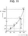
- FIG. 11 shows a saturated vapor pressure curve at 1 atmospheric pressure.
- a vertical axis represents saturated vapor pressure, and a horizontal axis represents temperature.
- the upper limit of the amount of water vapor that air can contain in other words, the upper limit of the partial pressure of water vapor (vapor pressure) in air depends on temperature.
- the vapor pressure cannot be physically changed to a value as high as that at a point D at 100 degrees centigrade. Accordingly, it is required to prepare the large-volume humidification chamber 220 (see FIG. 10B ) and vaporize a large amount of water by boiling. In this case, however, there is concern that the temperature of the fed gas rises too high. On the contrary, in a case where the medical gas is supplied at a low flow rate, the water vapor itself used for humidification can be easily produced, even if the temperature inside the humidification chamber 220 is lower than the boiling point of water, i.e. 100 degrees centigrade, for example, at a point C of FIG. 11 .
- the present invention aims at providing a humidifier that can easily control temperature and humidity in an independent manner irrespective of a flow rate of medical gas to be supplied.
- the invention described in (23) above has the beneficial effect that it is possible to provide the respiratory assistance device including the humidifier that can independently regulate the temperature and humidity, even with a high flow rate or a low flow rate.
- the present invention provides a humidifier that is connected to a respiratory assistance device configured to regulate or assist ventilation of the user.
- the humidifier is configured to make the liquid containing at least the water into mist droplets, make the water retaining member temporarily hold the mist droplets, make the fed gas be brought into contact the water retaining member to humidify the gas, and supply the user with the humidified gas.
- the present invention also provides a respiratory assistance device including the humidifier.
- the humidifier since the generation of the mist droplets, i.e. the minute water particles contained in the liquid, promotes the vaporization to the water vapor, the humidifier that humidifies the gas fed to the user can be realized.
- the present invention has the beneficial effect that, since the humidifier has the water retaining member configured to hold at least a part of the mist droplets in a liquid form, the moisture adhering to the water retaining member can further humidify the gas.
- FIGS. 1 to 9 show an example of the embodiments of the present invention.
- components indicated with the same reference numerals are identical components, and the fundamental configuration thereof is the same as conventional one shown in the drawings.
- the configuration is partly omitted for the sake of simplicity of the drawings.
- the size, shape, thickness, and the like of components are emphasized in an appropriate manner.
- FIG. 1 is a cross-sectional view of a humidifier 10 according to a first embodiment of the present invention.
- the humidifier 10 just as with the conventional humidifier 10 provided in the conventional respiratory assistance device (see FIG. 10A ), is connected to a respiratory assistance device configured to regulate or assist ventilation in a respirator of a user, to add moisture in the form of fine particles or water vapor to a gas fed from a gas source.
- the humidifier is connected between a gas source (ventilator) 280 of a medical gas and a mask 260 (see FIG. 10 A) configured to supply the user with the medical gas.
- the humidifier 10 is disposed between a ventilator-side pipe 90 and a breathing circuit-side pipe 110.
- the humidifier 10 includes a liquid container 80 configured to contain liquid including at least water, a mist-droplet generation unit 70 configured to generate mist droplets, i.e. minute droplets of the liquid, and a water retaining member 20 configured to hold at least a part of the mist droplets.
- the mist-droplet generation unit 70 is caused to generate the mist droplets by ultrasonic vibration, as described later.
- the mist-droplet generation unit 70 has an ultrasonic generation unit configured to generate the mist droplets by adding vibration to the liquid.
- the mist-droplet generation unit 70 is an ultrasonic mist-droplet generation unit configured to use so-called cavitation effect that generates air bubbles on a liquid surface by a vibration energy from an ultrasonic oscillator.
- the mist-droplet generation unit 70 includes a case 55, an ultrasonic oscillator 60, and an ultrasonic transfer material 50.
- the ultrasonic transfer material 50 is, for example, water.
- the water that is the ultrasonic transfer material 50 held in the case 55, as well as water 40 that is brought into contact with the case 55 through a case 25, has a high specific heat, and hence has high resistant to increase in temperature. Therefore, the water is suitable for long time use on the whole of the humidifier 10.
- the mist-droplet generation unit 70 and the liquid container 80 are tightly attached to each other through an ultrasonic transferable material, such as a nonvolatile oil, at a boundary 85 therebetween.
- the ultrasonic oscillator 60 is controlled by a controller 130 (not illustrated).
- the controller 130 includes a CPU, a RAM, a ROM, and the like to perform entire control of the humidifier 10.
- the CPU is a so-called central processing unit that performs various functions by execution of various types of programs.
- the RAM is used as an operation area and a memory area of the CPU.
- the ROM stores an operating system and the programs executed by the CPU.
- the controller 130 preferably has the functions of monitoring a thermometer 100, a thermometer (not illustrated) in the vicinity of the mask 260 (see FIG.
- a flowmeter (not illustrated) for the fed gas, and the like, and performing feedback control (PID control) of a heater and the like of a droplet heating unit 30, to perform adjustment at a predetermined temperature and humidity.
- PID control feedback control
- a mist-droplet generation amount by the mist-droplet generation unit 70 is controlled by the controller 130. For example, when an alternating current voltage to be applied to the ultrasonic oscillator 60 has an increased amplitude, the vibration of the ultrasonic oscillator 60 has an increased amplitude, and therefore the mist-droplet generation amount is increased.
- the liquid container 80 may be preferably taken out of the case 25.
- the mist-droplet generation unit 70 may also be preferably taken out of the liquid container 80.
- the humidifier 10 has a passage configured to allow the fed gas to pass therethrough.
- the passage is closed by the water retaining member 20.
- the water retaining member 20 partitions the passage into an upstream side that is on the side of the gas source (ventilator) 280 and has the liquid container 80 and the mist-droplet generation unit 70, and a downstream side that is on the side of the user.
- the water retaining member 20 has gas permeability, and has a tubular structure that is closed at one end on the side of the user, and is open at the other end on the side of the gas source (ventilator) 280.
- the gas penetrates the inside of the water retaining member 20 through an opening 19, passes through the water retaining member 20, and is released into the breathing circuit-side pipe 110.
- the opening 19 of the tube of the water retaining member 20 is joined to an inner peripheral surface of the case 25 at its end part, so as to close the passage.
- a gas flow area is preferably increased. Therefore, a spacer is preferably provided between the tubular water retaining member 20 and the inner peripheral surface of the case 25, to secure a gap therebetween. Instead of providing the spacer, the diameter of the tube of the water retaining member 20 may be made sufficiently smaller than the internal diameter of the case 25, to secure a gap therebetween.
- the water retaining member 20 is preferably made of a water absorptive nonwoven fabric, and is preferably an exchangeable member.
- the material of the nonwoven fabric of the water retaining member 20 is, for example, polypropylene to which a surface-active agent treatment, a fluoride gas treatment, a sulfonation treatment, an acrylic acid graft treatment, a plasma discharge treatment, or the like is preferably applied to impart hydrophilicity thereto.
- the water retaining member 20 is disposed in the case 25.
- the droplet heating unit 30, which heats at least one of droplets, i.e., the mist droplets and moisture held in the water retaining member and vaporizes the mist droplets or the moisture into water vapor, is disposed inside the water retaining member 20 on the side of the liquid container 80.
- the droplet heating unit 30 is a resistance heater made of, for example, a nichrome wire or the like, and is connected to a power supply (not illustrated).
- the controller 130 controls electric power on the basis of the temperature detected by the thermometer 100 and the like, to control temperature and humidity.
- the water retaining member 20 blocks the mist droplets, while allowing gas containing the water vapor to pass therethrough.
- a dry medical gas is supplied from the ventilator-side pipe 90 to the humidifier 10.
- the role of the humidifier 10 is to add moisture to the medical gas, and humidification is performed by the following two methods.
- the water vapor for humidification is generated with a lower energy than general vaporization by boiling. Since a large amount of water vapor can be generated without boiling the stored water 40, the humidifier 10 has the beneficial effect of controlling the humidity independently of the temperature, without excessively increasing the temperature of the medical gas. Since the water retaining member 20 filters the fed gas, the water retaining member 20 has the effect of playing a role as a bacteria filter, as well as a humidifier.
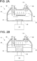
- FIG. 2A is a cross-sectional view of a humidifier 10 according to a second embodiment of the present invention.
- water 40 is stored in a case 25.
- a water retaining member 20 partitions a droplet heating unit 30 and the water 40 from a breathing circuit-side pipe 110.
- the water retaining member 20 is made of a nonwoven fabric.
- the water retaining member 20 is in a plane shape, and is joined to an inner side surface of the case 25 at its end.
- the water retaining member 20 entirely covers the liquid 40.
- a gas fed from a ventilator-side pipe 90 necessarily passes through the water retaining member 20.
- the ventilator-side pipe 90 is disposed inside the water retaining member 20, in other words, so as to feed the gas to the side of the liquid 40.
- a mist-droplet generation unit 70 of the humidifier 10 is a steam-type mist-droplet generation unit having a liquid heating unit configured to heat the liquid to vaporize the water 40 contained in the liquid.
- the droplet heating unit 30 configured to heat at least one of mist droplets and moisture held by the water retaining member to vaporize the mist droplets or moisture into water vapor is disposed inside the water retaining member 20, in other words, on the side of the water 40.
- the droplet heating unit 30 is a resistance heater made of, for example, a nichrome wire or the like, and is controlled by the controller 130 at a predetermined temperature.
- the present second embodiment adopts a method in which the water 40 is vaporized by heating to increase vapor pressure. Since humidification can be performed while the water stored in the liquid container is sterilized, the humidifier is easily kept in a good hygiene state, and the fed gas is filtered by the water retaining member 20. In other words, the water retaining member 20 has the effect of playing a role as a bacteria filter, as well as a humidifier.
- the droplet heating unit 30 may be integrally formed with the water retaining member 20, or may be provided outside the water retaining member 20, in other words, on the side of an inspiratory pipe or on the side of the case.
- the positional relationship between the water retaining member 20 and the droplet heating unit 30 is the same as those in the other embodiments and modification embodiments.
- the droplet heating unit 30 may be disposed inside or outside the water retaining member 20, and the water retaining member 20 and the droplet heating unit 30 may be integrated with each other.
- FIG. 2B shows a humidifier 10 according to a modification embodiment of the second embodiment of the present invention.
- a liquid heating unit constituting the mist-droplet generation unit 70 is a heating unit 120 that is integrated with the droplet heating unit 30 configured to heat at least one of the mist droplets and moisture held by the water retaining member to vaporize the mist droplets or moisture.
- a part of the heating unit 120 is exposed upward from a liquid surface, to heat at least one of the mist droplets and the moisture held in the water retaining member to vaporize the mist droplets or moisture.
- the heating unit 120 is, for example, a resistance heater, and is controlled by a controller 130 at a predetermined temperature.
- the present embodiment has the beneficial effect of facilitating temperature control.
- the vapor pressure of the gas fed from the ventilator-side pipe 90 is increased with the water vapor vaporized by the heating unit 120.
- the gas is filtered by the water retaining member 20, and is fed to the breathing circuit-side pipe 110.
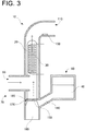
- FIG. 3 is a cross-sectional view showing a configuration of a humidifier 10 according to a third embodiment of the present invention.
- a mist-droplet generation unit 70 of the humidifier 10 has the same configuration as a mesh-type spraying unit, which is a unit configured to realize a nebulizer (a device configured to generate minute mists containing pharmaceutical drugs for an aerosol inhalation therapy or a nebulization therapy).
- the mist-droplet generation unit 70 includes a vibration generation device 160 and a mesh 180 having many minute pores. A gap between an oscillator 150 of the vibration generation device 160 and the mesh 180 is filled with water 170. By causing the vibration generation device 160 to vibrate, mist droplets are generated.
- the advantages of this configuration are small size and good controllability.
- the humidifier 10 can be made extremely compact as a whole, and accordingly, the respiratory assistance device 1 has good transportability.
- the mist droplets can be generated from a small amount of water.
- the mist droplets generated by the mesh-type mist-droplet generation unit 70 are heated by the droplet heating unit 30, and are vaporized into water vapor to humidify a gas fed from the ventilator-side pipe 90.
- FIG. 4 is a cross-sectional view showing a configuration of a humidifier 10 according to a fourth embodiment of the present invention.
- a mist-droplet generation unit 70 of the humidifier 10 has the same configuration as a spraying unit of a so-called compressor-type or jet-type nebulizer.
- compressed air fed from a compressor-side pipe 195 is ejected at high speed from a nozzle 210, ambient pressure is reduced using the Venturi effect, and water 40 is sucked up from a water inlet pipe 200.
- the sucked water 40 lively bumps against a baffle 190 to generate mist droplets.
- the humidifier having the jet-type mist-droplet generation unit 70 using the compressed air offers the advantages of ease in structure, ease in maintenance, ease in keeping in a good hygiene state.
- the mist droplets generated by the mist-droplet generation unit 70 are heated by the droplet heating unit 30, and are vaporized into water vapor to humidify a gas fed from the ventilator-side pipe 90.
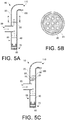
- FIG. 5A is a cross-sectional view showing a configuration of a humidifier 10 according to an example for better understanding the present invention.
- the humidifier 10 includes a case 25, a mist-droplet generation unit 70, a liquid container 80, and a water retaining member 20.
- FIG. 5A shows an example in which the mist-droplet generation unit 70 has the ultrasonic generation unit configured to generate mist droplets by applying vibration to liquid.
- the mist-droplet generation unit 70 may have a liquid heating unit configured to heat the liquid to vaporize water contained in liquid 40, to generate mist droplets, may have a mesh-type mist-droplet generation unit, or may have a jet-type mist-droplet generation unit.
- the humidifier 10 has a passage configured to allow fed gas to pass therethrough.
- the passage is closed by the water retaining member 20.
- the water retaining member 20 partitions the passage into an upstream side that is on the side of a gas source (ventilator) 280 and has the liquid container 80 and the mist-droplet generation unit 70, and a downstream side that is on the side of a user.
- a gas source ventilation unit
- an end part of the water retaining member 20 is joined to the case 25 so as to close the passage.
- the water retaining member 20 blocks the mist droplets, while allowing a gas containing water vapor to pass therethrough.
- FIG. 5B shows a modification embodiment of the water retaining member 20 shown in FIG. 5A.
- FIG. 5B is a cross-sectional view taken along line A-A of FIG. 5A , i.e. sectioned in a virtual plane represented by alternate short and long dashed lines.
- a plurality of holes through which gas containing mist droplets can pass are formed in the water retaining member 20.
- the gas When a user inspires a gas having a relative humidity of 100% at a low temperature and a low absolute humidity value, the gas absorbs moisture in a respiratory tract, while being humidified in the respiratory tract. This may cause fixation of secretion and the like in a wide area extending to a peripheral respiratory tract.
- the present modification embodiment has an advantage that there is no possibility of drying up the inside of the respiratory tract.
- the present modification embodiment offers the above beneficial effect, owing to the plurality of holes through which the gas containing the mist droplets can pass.
- FIG. 5C is a cross-sectional view of a humidifier according to another example for better understanding the present invention.
- a plurality of water retaining members 20 is provided, and each of the water retaining members 20 partially closes a passage.
- the water retaining members 20 are configured to have a shape protruding perpendicularly from a case 25 to a passage, for example, in a staggered manner, such that a gas containing mist droplets does not flow without any obstacle. According to this shape, the mist droplets collide against the water retaining members 20, and are held in the water retaining members 20. A gas containing water vapor is fed to a user with less resistance.
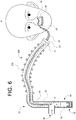
- FIG. 6 is an explanatory view of a humidifier 10 according to a fifth embodiment of the present invention.
- the humidifier 10 includes a liquid container 80 that is disposed between the ventilator-side pipe 90 and the breathing circuit-side pipe 110 and contains liquid including at least water, a mist-droplet generation unit 70 configured to generate mist droplets, i.e. minute droplets of the liquid, and a water retaining member 20 configured to hold at least a part of the mist droplets.
- the inspiratory pipe 250 is connected to a pipe 26 through a connector 23, and the pipe 26 is connected to a housing 28.
- a gas is fed into nasal cavities of a user P through a nasal prong 29 supported by the housing 28.
- a water retaining member 24 is provided as a droplet absorbing unit.
- droplets may enter a respiratory tract together with the fed medical gas. Since bacteria tend to occur in liquid water, the entry of the droplets into the respiratory tract may cause pneumonia. Disposing the water retaining member 24 in the vicinity of the nasal prong 29 has the significant effect of preventing the droplets from entering the respiratory tract, by absorbing the condensed droplets.
- the water retaining member 20 is preferably divided into at least two members, which are disposed separately.
- the water retaining member 20 on the side of the humidifier 10 is always supplied with mist droplets, and is in a wet state, in principle.
- the water retaining member 24 disposed in the vicinity of the nasal prong 29 aims at absorbing droplets, and is preferably dry. Therefore, by dividing the water retaining member 20 into at least two members, i.e. into the water retaining member 20 and the water retaining member 24, as shown in FIG. 6 , the water retaining members can play different roles as a water retaining member for humidification and a water retaining member for absorption.
- a major feature of the present embodiment is that the water retaining member 20 extends to the inside of the inspiratory pipe 250.
- the water retaining member 20 is provided inside the inspiratory pipe of the breathing circuit provided to the respiratory assistance device 1 along a longitudinal direction, and the length of the water retaining member 20 is 50 cm or more.
- the length of the water retaining member 20 is 50 cm or more, and more preferably 1 m or more. According to this configuration, the water retaining member 20 has an extremely wide surface area, thus having the extremely significant effect of facilitating vaporization of moisture held in the water retaining member 20.
- the water retaining member 20 containing moisture is present along an inner wall of the inspiratory pipe 250, when the inspiratory pipe 250 of the breathing circuit is heated with an anti-condensation heater attached thereto, the majority of the heat is used for evaporating the moisture from the water retaining member 20, thus having the beneficial effect of preventing an increase in temperature of the inspiratory pipe 250.
- the water retaining member 20 has gas permeability, and has a tubular structure that is closed at one end on the side of the user P, i.e. a water retaining member end part 22, and is open at the other end on the side of the gas source (ventilator) 280.
- the gas penetrates the inside of the water retaining member 20 through an opening 19, passes through the water retaining member, and is released into the inspiratory pipe 250.
- the droplet heating unit 30, configured to heat the mist droplets and the moisture held in the water retaining member 20 to vaporize them into water vapor, is provided inside the water retaining member 20.
- the droplet heating unit 30 is controlled by a controller 130 (not illustrated) at a predetermined temperature.
- the droplet heating unit 30 is a resistance heater made of, for example, a nichrome wire or the like.
- the droplet heating unit 30 controls temperature and humidity using the controller 130 on the basis of the temperature detected by a thermometer (not illustrated) and the like provided in the inspiratory pipe 250.
- a thermometer not illustrated
- FIG. 8 when the water retaining member 20 is made of a soft material, providing the droplet heating unit 30 in an inscribed manner in the water retaining member 20 facilitates keeping the shape of the water retaining member 20. In other words, a space is maintained inside the water retaining member 20, thus having the effect of keeping a sufficient surface area for evaporation.
- the diameters of mesh pores are preferably smaller than the diameters of mist droplets.
- the droplet heating unit 30 may be provided in a circumscribed manner on the water retaining member 20, or the droplet heating unit 30 may be embedded in fibers constituting the water retaining member 20.
- the droplet heating unit 30 may be provided in an inscribed or circumscribed manner in or on the inspiratory pipe 250 itself of the breathing circuit provided in a respiratory assistance device.
- an anti-condensation heating unit 270 of the inspiratory pipe 250 that doubles as a droplet heating unit 30, without providing the droplet heating unit 30 in the vicinity of the water retaining member 20, produces a sufficient humidification effect.
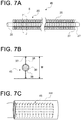
- FIG. 7A is an explanatory view of a humidification member 45 that extends to the inside of the inspiratory pipe 250 in the respiratory assistance device according to the fifth embodiment.
- the droplet heating unit 30 in FIG. 6 is a coil heater, but the droplet heating unit 30 in FIG. 7A is a linear resistance heater.
- the humidification member 45 includes the droplet heating unit 30 and a water retaining member 20.
- the water retaining member 20 is made of woven fibers 35.
- the shape of the water retaining member 20 is stabilized by a core 37.
- the core 37 may be made of the same material as the fibers 35, or may be made of thicker fibers than the fibers 35 constituting the water retaining member 20.
- the fibers preferably have an affinity for water, but may be hydrophobic.
- Droplets are caught inside the fibers 35 or between the fibers 35.
- the fibers are preferably soft and easily deformable by fingers even in a woven state.
- the caught moisture is heated by the droplet heating unit 30 to become water vapor, and is supplied to the user P through the medical gas.
- FIG. 7B is a cross-sectional view of the humidification member 45 taken along a virtual plane S perpendicular to the droplet heating unit 30 (see FIG. 7A ).
- the water retaining member 20 made of woven fibers 35 is provided with plate-shaped parts 38 and a pipe-shaped part 39 configured to cover the droplet heating unit 30.
- the width W of the humidification member 45 is preferably 5 mm or more.
- the provision of the plate-shaped parts 38 has the effect of increasing the area of members that easily contain droplets.
- the water retaining member 20 may be made only of the pipe-shaped part 39 configured to cover the droplet heating unit 30, in effect.
- FIG. 7C is an explanatory view of a structure in which a humidification member formed into a coil shape is disposed in a hose 250 of the breathing circuit.
- FIG. 7C shows only a part of the hose 250.
- the humidification member 45 is disposed inside the hose 250 in a state of being wound into a coil shape.
- the humidification member 45 is preferably inscribed in the hose 250. According to this configuration, the water retaining member 20 can absorb water droplets adhering to an internal wall of the hose 250, and the water droplets can be made into water vapor by being heated by the droplet heating unit 30.
- a shield member such as the water retaining member 20 shown in FIG. 5A , that allows gas to pass therethrough while catching droplets, is preferably disposed inside or in the vicinity of the humidifier 10 in such a manner as to block a flow path so that droplets contained in the fed medical gas do not directly reach the lungs of the user P.
- the water retaining member 20 may be made of a nonwoven fabric. In this case, the water retaining member 20 preferably covers the droplet heating unit 30 in a tubular manner.
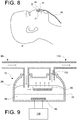
- FIG. 8 is a partly enlarged explanatory view of a respiratory assistance device according to an eighth embodiment of the present invention.
- a nasal prong 29 is inserted into nasal cavities of a user P, and a medical gas is fed from a pipe 26 to the user P through a housing 28 configured to support the nasal prong 29.
- the housing 28 configured to support the nasal prong 29 has a drain hole 31.
- the drain hole 31 is preferably provided in the housing 28 at a position near the user P, such that, when the user P lies down, accumulated droplets easily drain.
- a water retaining member 24 (not illustrated) is disposed inside the housing 28, droplets beyond absorption drain out of the housing 28 through the drain hole 31.
- pipe attachment holes 32 are provided on both sides of the housing 28 to connect a pipe 26 therethrough and the pipe attachment hole 32 is clogged with a plug, it is conceivable to provide a drain hole 31 in the plug itself.
- the pipe attachment hole 32 may double as the drain hole 31.
- Embodiments of the present invention are not limited to the embodiments described above, but can be variously modified, as a matter of course, without departing from the scope of the present invention. As a modification example of each of the embodiments, it is conceivable to apply the following embodiment.
- the entire gas humidified with the water vapor generated in the liquid container 80 is fed into the breathing circuit-side pipe 110, after being filtered with the water retaining member 20.
- a part of the fed gas may pass through the inside of the water retaining member 20, while the remaining part of the gas may not pass through the inside of the water retaining member 20.
- a part of a gas fed from the ventilator-side pipe 90 may be branched upstream of the humidifier 10, and may be merged with humidified gas downstream of the humidifier 10 at a breathing circuit on the side of a user.
- the modification embodiment has the effect of reducing a resistance load of breathing.
Landscapes
- Health & Medical Sciences (AREA)
- Life Sciences & Earth Sciences (AREA)
- General Health & Medical Sciences (AREA)
- Engineering & Computer Science (AREA)
- Anesthesiology (AREA)
- Biomedical Technology (AREA)
- Heart & Thoracic Surgery (AREA)
- Veterinary Medicine (AREA)
- Hematology (AREA)
- Animal Behavior & Ethology (AREA)
- Public Health (AREA)
- Pulmonology (AREA)
- Emergency Medicine (AREA)
- Otolaryngology (AREA)
- Chemical & Material Sciences (AREA)
- Dispersion Chemistry (AREA)
- Air Humidification (AREA)
Claims (19)
- Luftbefeuchter (10), der mit einer Atemunterstützungsvorrichtung (1) verbunden sein soll, die dazu eingerichtet ist, um die Atmung eines Benutzers (P) zu regulieren oder zu unterstützen, wobei der Luftbefeuchter (10) dazu eingerichtet ist, um einem Gas, das von einer Gasquelle (280) in Form von feinen Partikeln oder Wasserdampf zugeführt wird, Feuchtigkeit hinzuzufügen, wobei der Luftbefeuchter (10) umfasst:einen Flüssigkeitsbehälter (80), der dazu eingerichtet ist, um eine Flüssigkeit zu enthalten, die mindestens Wasser enthält;eine Nebeltröpfchenerzeugungseinheit (70), die dazu eingerichtet ist, um Nebeltröpfchen zu erzeugen, die feine Partikel der Flüssigkeit sind; undein Wasserrückhalteelement (20), das dazu eingerichtet ist, um mindestens einen Teil der Nebeltröpfchen zu halten,dadurch gekennzeichnet, dassdas Wasserrückhalteelement (20) dafür geeignet ist in einem Beatmungsschlauch (250) eines Atemkreislaufs bereitgestellt zu sein, der in der Atemunterstützungsvorrichtung (1) entlang einer Längsrichtung des Beatmungsschlauchs (250) bereitgestellt ist, unddas Wasserrückhalteelement (20) eine Länge von 50 cm oder mehr aufweist.
- Luftbefeuchter (10) nach Anspruch 1, wobei
das Wasserrückhalteelement (20) eine Gasdurchlässigkeit aufweist und eine röhrenförmige Struktur aufweist, die an einem Ende auf einer Seite des Benutzers (P) geschlossen ist und am anderen Ende einer Seite der Gasquelle (280) eine Öffnung aufweist, und
das Gas durch die Öffnung in ein Inneres des Wasserrückhalteelements (20) eindringt, durch das Wasserrückhalteelement (20) tritt, und an dessen Außenseite abgegeben wird. - Luftbefeuchter (10) nach Anspruch 1, mit einer Tröpfchenheizeinheit (30), die dazu eingerichtet ist, um mindestens die Nebeltröpfchen oder die Feuchtigkeit zu erwärmen, die von dem Wasserrückhalteelement (20) gehalten wird, um die Nebeltröpfchen oder die Feuchtigkeit in den Wasserdampf zu verdampfen.
- Luftbefeuchter (10) nach Anspruch 3, wobei die Tröpfchenheizeinheit (30) in einer eingefassten oder umlaufenden Art und Weise in oder auf einem Beatmungsschlauch (250) eines in der Atemunterstützungsvorrichtung (1) bereitgestellten Atemkreislaufs bereitgestellt ist.
- Luftbefeuchter (10) nach Anspruch 3, wobei die Tröpfchenheizeinheit (30) in einer eingefassten oder umlaufenden Art und Weise in oder auf dem Wasserrückhalteelement (20) bereitgestellt ist.
- Luftbefeuchter (10) nach Anspruch 1, wobei ein Dampfdruck des Gases durch Feuchtigkeit erhöht wird, die von dem Wasserrückhalteelement (20) gehalten wird.
- Luftbefeuchter (10) nach Anspruch 1, wobei das Wasserrückhalteelement (20) ein austauschbares Element ist.
- Luftbefeuchter (10) nach Anspruch 1, wobei das Wasserrückhalteelement (20) eine Wasserabsorptionseigenschaft aufweist.
- Luftbefeuchter (10) nach Anspruch 1, wobei das Wasserrückhalteelement (20) aus einem Vliesstoff besteht.
- Luftbefeuchter (10) nach Anspruch 1, wobei ein Teil des Gases durch ein Inneres des Wasserrückhalteelements (20) strömt und ein verbleibender Teil des Gases nicht durch das Innere des Wasserrückhalteelements (20) strömt.
- Luftbefeuchter (10) nach Anspruch 10, wobei ein Ende des Wasserrückhalteelements (20), das an der Seite der Gasquelle (280) offen ist, mit einer inneren Umfangsoberfläche des Luftbefeuchters (10) verbunden ist und das Wasserrückhalteelement (20) einen Durchgang schließt, durch den das Gas strömt.
- Luftbefeuchter (10) nach Anspruch 11, wobei
der Luftbefeuchter (10) einen Durchgang aufweist, durch den das Gas strömt,
der Durchgang durch das Wasserrückhalteelement (20) verschlossen ist und
das Wasserrückhalteelement (20) den Durchgang unterteilt ineine stromaufwärtige Seite, die sich auf einer Seite der Gasquelle (280) befindet und den Flüssigkeitsbehälter (80) und die Nebeltröpfchenerzeugungseinheit (70) aufweist, undeine stromabwärtige Seite, die sich auf einer Seite des Benutzers (P) befindet. - Luftbefeuchter (10) nach Anspruch 1, wobei die Nebeltröpfchenerzeugungseinheit (70) eine Flüssigkeitsheizeinheit aufweist, die dazu eingerichtet ist, um die Flüssigkeit zu erhitzen, um das in der Flüssigkeit enthaltene Wasser zu verdampfen.
- Luftbefeuchter (10) nach Anspruch 3, wobei die Nebeltröpfchenerzeugungseinheit (70) eine Flüssigkeitsheizeinheit aufweist, die dazu eingerichtet ist, um die Flüssigkeit zu erhitzen, um das in der Flüssigkeit enthaltene Wasser zu verdampfen, und die Flüssigkeitsheizeinheit in die Tröpfchenheizeinheit (30) integriert ist.
- Luftbefeuchter (10) nach Anspruch 1, wobei die Nebeltröpfchenerzeugungseinheit (70) eine Ultraschallerzeugungseinheit aufweist, die dazu eingerichtet ist, um die Flüssigkeit zu vibrieren, um die Nebeltröpfchen zu erzeugen.
- Luftbefeuchter (10) nach Anspruch 1, wobei
die Nebeltröpfchenerzeugungseinheit (70)eine Vibrationserzeugungsvorrichtung (160) undein Netz (180) mit vielen winzigen Porenenthält. - Luftbefeuchter (10) nach Anspruch 1, wobei die Nebeltröpfchenerzeugungseinheit (70) eine Strahlentyp-Nebeltröpfchenerzeugungseinheit (70) aufweist, die dazu eingerichtet ist, um komprimierte Luft zu verwenden.
- Luftbefeuchter (10) nach Anspruch 1, wobei
das Wasserrückhalteelement (20) ferner in der Nähe eines Nasenstifts (29) angeordnet, der dazu eingerichtet ist, um das Gas den Nasenhöhlen des Benutzers (P) zuzuführen,
ein Gehäuse (28), das dazu eingerichtet ist, um den Nasenstift (29) zu unterstützen, mindestens ein Abflussloch (31) aufweist, das dazu eingerichtet ist, um Kondenswasser abzulassen. - Atemunterstützungsvorrichtung (1), die dazu eingerichtet ist, um die Atmung eines Benutzers (P) zu regulieren oder zu unterstützen, wobei die Atemunterstützungsvorrichtung (1) den Luftbefeuchter (10) umfasst, der mit Merkmalen nach Anspruch 1 bereitgestellt ist.
Applications Claiming Priority (3)
| Application Number | Priority Date | Filing Date | Title |
|---|---|---|---|
| JP2016080251 | 2016-04-13 | ||
| JP2016124251 | 2016-06-23 | ||
| PCT/JP2017/014810 WO2017179569A1 (ja) | 2016-04-13 | 2017-04-11 | 加湿器、呼吸補助装置 |
Publications (3)
| Publication Number | Publication Date |
|---|---|
| EP3437686A1 EP3437686A1 (de) | 2019-02-06 |
| EP3437686A4 EP3437686A4 (de) | 2019-04-24 |
| EP3437686B1 true EP3437686B1 (de) | 2021-06-02 |
Family
ID=60042595
Family Applications (1)
| Application Number | Title | Priority Date | Filing Date |
|---|---|---|---|
| EP17782382.0A Active EP3437686B1 (de) | 2016-04-13 | 2017-04-11 | Befeuchter und beatmungsunterstützungsvorrichtung |
Country Status (5)
| Country | Link |
|---|---|
| US (1) | US11305089B2 (de) |
| EP (1) | EP3437686B1 (de) |
| JP (1) | JP6882783B2 (de) |
| CN (1) | CN109069785B (de) |
| WO (1) | WO2017179569A1 (de) |
Families Citing this family (10)
| Publication number | Priority date | Publication date | Assignee | Title |
|---|---|---|---|---|
| US11207487B2 (en) * | 2016-01-21 | 2021-12-28 | Fisher & Paykel Healthcare Limited | System for humidification of medical gases |
| CN110170099B (zh) * | 2019-07-03 | 2024-12-27 | 绍兴安迪斯医疗科技有限公司 | 一种呼吸机用加湿加热系统 |
| CN110585548B (zh) * | 2019-09-12 | 2022-09-02 | 绍兴安迪斯医疗科技有限公司 | 一种雾化加热装置及其实现方法 |
| CN111380134A (zh) * | 2020-03-18 | 2020-07-07 | 绍兴安迪斯医疗科技有限公司 | 一种加温加湿器及其加温加湿方法 |
| IL275477B (en) * | 2020-06-17 | 2022-02-01 | Uri Haimi Shlomo | Device and method for use in treatment of pathogens |
| CN111939421A (zh) * | 2020-07-24 | 2020-11-17 | 天津怡和嘉业医疗科技有限公司 | 通气治疗设备 |
| CN111773501B (zh) * | 2020-08-27 | 2022-11-08 | 刘静 | 一种呼吸机气体加热加湿装置 |
| WO2022050852A1 (en) * | 2020-09-04 | 2022-03-10 | Fisher & Paykel Healthcare Limited | Patient interface for delivery of gas |
| CN113304375B (zh) * | 2021-05-12 | 2023-06-27 | 湖南万脉医疗科技有限公司 | 一种新型呼吸机管路及其呼吸机 |
| US20230191068A1 (en) * | 2021-12-22 | 2023-06-22 | Covidien Lp | Vaporization configurations for breathing gases humidifier |
Family Cites Families (20)
| Publication number | Priority date | Publication date | Assignee | Title |
|---|---|---|---|---|
| JPS5575143A (en) * | 1978-11-30 | 1980-06-06 | Hitachi Heating Appliance Co Ltd | Humidifier |
| JPS55157634U (de) * | 1979-04-28 | 1980-11-12 | ||
| JPH0420452Y2 (de) * | 1985-12-13 | 1992-05-11 | ||
| US4921642A (en) | 1987-12-03 | 1990-05-01 | Puritan-Bennett Corporation | Humidifier module for use in a gas humidification assembly |
| JP2001241709A (ja) * | 2000-02-29 | 2001-09-07 | Motonori Ooi | 熱風気化式加湿器 |
| US6918389B2 (en) | 2000-03-21 | 2005-07-19 | Fisher & Paykel Healthcare Limited | Breathing assistance apparatus |
| JP4675566B2 (ja) | 2002-01-25 | 2011-04-27 | パナソニックエコシステムズ株式会社 | 吸入器 |
| WO2008095245A1 (en) * | 2007-02-09 | 2008-08-14 | Resmed Ltd | Humidification arrangement for a respiratory apparatus |
| US20090025724A1 (en) * | 2007-07-16 | 2009-01-29 | Herron Jr Roy Howard | System for removal of water from a hose and the hygroscopic hose utilized |
| NZ581899A (en) * | 2007-07-31 | 2012-03-30 | Resmed Ltd | An apparatus for delivering breathable gas to a patient comprising a heating element extending through the flow paths and the humidifier chamber |
| JP5288776B2 (ja) | 2007-11-26 | 2013-09-11 | 株式会社クボタ | 空気調和機 |
| US20120012108A1 (en) * | 2009-04-06 | 2012-01-19 | Yasuhiko Sata | Artificial nose and breathing circuit provided with the artificial airway |
| AU2011308548B2 (en) * | 2010-09-30 | 2014-10-23 | Breathe Technologies, Inc. | Methods, systems and devices for humidifying a respiratory tract |
| US9314582B2 (en) * | 2010-11-23 | 2016-04-19 | Carefusion 2200, Inc. | Humidification system |
| JP5992139B2 (ja) * | 2010-12-08 | 2016-09-14 | 三機工業株式会社 | 水噴霧加湿装置 |
| EP2651482B1 (de) * | 2010-12-17 | 2019-05-15 | Koninklijke Philips N.V. | Befeuchtersystem zum befeuchten von an einen patienten verabreichtem atemgas |
| CA2894279A1 (en) * | 2012-12-07 | 2014-06-12 | Paul Boucher | Nasal cannula for delivery of aerosolized medicaments |
| CA3175235A1 (en) * | 2014-09-03 | 2016-03-10 | Fisher & Paykel Healthcare Limited | Deterministically controlled humidification system |
| CN204379943U (zh) * | 2014-12-30 | 2015-06-10 | 东莞永胜医疗制品有限公司 | 一种呼吸气体湿化装置 |
| EP4289462A3 (de) * | 2015-03-31 | 2024-01-10 | Fisher & Paykel Healthcare Limited | Vorrichtung zur verwendung in einem atemunterstützungssystem |
-
2017
- 2017-04-11 EP EP17782382.0A patent/EP3437686B1/de active Active
- 2017-04-11 CN CN201780023531.4A patent/CN109069785B/zh active Active
- 2017-04-11 JP JP2018512019A patent/JP6882783B2/ja active Active
- 2017-04-11 WO PCT/JP2017/014810 patent/WO2017179569A1/ja not_active Ceased
- 2017-04-11 US US16/092,891 patent/US11305089B2/en active Active
Non-Patent Citations (1)
| Title |
|---|
| None * |
Also Published As
| Publication number | Publication date |
|---|---|
| EP3437686A4 (de) | 2019-04-24 |
| WO2017179569A1 (ja) | 2017-10-19 |
| CN109069785A (zh) | 2018-12-21 |
| US11305089B2 (en) | 2022-04-19 |
| JPWO2017179569A1 (ja) | 2019-02-21 |
| US20190134342A1 (en) | 2019-05-09 |
| EP3437686A1 (de) | 2019-02-06 |
| CN109069785B (zh) | 2021-04-02 |
| JP6882783B2 (ja) | 2021-06-02 |
Similar Documents
| Publication | Publication Date | Title |
|---|---|---|
| EP3437686B1 (de) | Befeuchter und beatmungsunterstützungsvorrichtung | |
| US11690972B2 (en) | Humidification system | |
| JP6297329B2 (ja) | 鼻インタフェース装置 | |
| US9272113B2 (en) | Transporting liquid in a respiratory component | |
| KR101313993B1 (ko) | 약물 흡입 장치 | |
| US20130284165A1 (en) | System and method for treating a medical condition using an aerosolized solution | |
| US8720439B1 (en) | Humidification for continuous positive airway pressure systems | |
| CN203954409U (zh) | 一种有/无创机械通气气体湿化加温系统 | |
| JP6091944B2 (ja) | 呼吸用ガスの加温加湿器 | |
| AU2015200180B2 (en) | Methods, systems and devices for humidifying a respiratory tract | |
| JPS637249Y2 (de) | ||
| EP3645087B1 (de) | Einsatz mit aerosolerzeuger für ein system zur befeuchtung eines unter druck stehenden durchflusses von atemgas, das einem patienten bereitgestellt wird | |
| KR20220105032A (ko) | 멤브레인 구조를 갖는 호흡순환튜브 |
Legal Events
| Date | Code | Title | Description |
|---|---|---|---|
| STAA | Information on the status of an ep patent application or granted ep patent |
Free format text: STATUS: THE INTERNATIONAL PUBLICATION HAS BEEN MADE |
|
| PUAI | Public reference made under article 153(3) epc to a published international application that has entered the european phase |
Free format text: ORIGINAL CODE: 0009012 |
|
| STAA | Information on the status of an ep patent application or granted ep patent |
Free format text: STATUS: REQUEST FOR EXAMINATION WAS MADE |
|
| 17P | Request for examination filed |
Effective date: 20181031 |
|
| AK | Designated contracting states |
Kind code of ref document: A1 Designated state(s): AL AT BE BG CH CY CZ DE DK EE ES FI FR GB GR HR HU IE IS IT LI LT LU LV MC MK MT NL NO PL PT RO RS SE SI SK SM TR |
|
| AX | Request for extension of the european patent |
Extension state: BA ME |
|
| STAA | Information on the status of an ep patent application or granted ep patent |
Free format text: STATUS: EXAMINATION IS IN PROGRESS |
|
| A4 | Supplementary search report drawn up and despatched |
Effective date: 20190326 |
|
| RIC1 | Information provided on ipc code assigned before grant |
Ipc: A61M 16/10 20060101ALI20190320BHEP Ipc: A61M 16/08 20060101ALI20190320BHEP Ipc: A61M 16/16 20060101AFI20190320BHEP Ipc: A61M 11/00 20060101ALI20190320BHEP Ipc: A61M 11/06 20060101ALI20190320BHEP Ipc: A61M 16/06 20060101ALI20190320BHEP |
|
| 17Q | First examination report despatched |
Effective date: 20190412 |
|
| DAV | Request for validation of the european patent (deleted) | ||
| DAX | Request for extension of the european patent (deleted) | ||
| GRAP | Despatch of communication of intention to grant a patent |
Free format text: ORIGINAL CODE: EPIDOSNIGR1 |
|
| STAA | Information on the status of an ep patent application or granted ep patent |
Free format text: STATUS: GRANT OF PATENT IS INTENDED |
|
| INTG | Intention to grant announced |
Effective date: 20201127 |
|
| GRAS | Grant fee paid |
Free format text: ORIGINAL CODE: EPIDOSNIGR3 |
|
| GRAA | (expected) grant |
Free format text: ORIGINAL CODE: 0009210 |
|
| STAA | Information on the status of an ep patent application or granted ep patent |
Free format text: STATUS: THE PATENT HAS BEEN GRANTED |
|
| REG | Reference to a national code |
Ref country code: CH Ref legal event code: EP |
|
| AK | Designated contracting states |
Kind code of ref document: B1 Designated state(s): AL AT BE BG CH CY CZ DE DK EE ES FI FR GB GR HR HU IE IS IT LI LT LU LV MC MK MT NL NO PL PT RO RS SE SI SK SM TR |
|
| REG | Reference to a national code |
Ref country code: GB Ref legal event code: FG4D |
|
| REG | Reference to a national code |
Ref country code: AT Ref legal event code: REF Ref document number: 1397864 Country of ref document: AT Kind code of ref document: T Effective date: 20210615 |
|
| REG | Reference to a national code |
Ref country code: IE Ref legal event code: FG4D |
|
| REG | Reference to a national code |
Ref country code: DE Ref legal event code: R096 Ref document number: 602017039724 Country of ref document: DE |
|
| REG | Reference to a national code |
Ref country code: LT Ref legal event code: MG9D |
|
| PG25 | Lapsed in a contracting state [announced via postgrant information from national office to epo] |
Ref country code: HR Free format text: LAPSE BECAUSE OF FAILURE TO SUBMIT A TRANSLATION OF THE DESCRIPTION OR TO PAY THE FEE WITHIN THE PRESCRIBED TIME-LIMIT Effective date: 20210602 Ref country code: BG Free format text: LAPSE BECAUSE OF FAILURE TO SUBMIT A TRANSLATION OF THE DESCRIPTION OR TO PAY THE FEE WITHIN THE PRESCRIBED TIME-LIMIT Effective date: 20210902 Ref country code: LT Free format text: LAPSE BECAUSE OF FAILURE TO SUBMIT A TRANSLATION OF THE DESCRIPTION OR TO PAY THE FEE WITHIN THE PRESCRIBED TIME-LIMIT Effective date: 20210602 Ref country code: FI Free format text: LAPSE BECAUSE OF FAILURE TO SUBMIT A TRANSLATION OF THE DESCRIPTION OR TO PAY THE FEE WITHIN THE PRESCRIBED TIME-LIMIT Effective date: 20210602 |
|
| REG | Reference to a national code |
Ref country code: NL Ref legal event code: MP Effective date: 20210602 |
|
| REG | Reference to a national code |
Ref country code: AT Ref legal event code: MK05 Ref document number: 1397864 Country of ref document: AT Kind code of ref document: T Effective date: 20210602 |
|
| PG25 | Lapsed in a contracting state [announced via postgrant information from national office to epo] |
Ref country code: SE Free format text: LAPSE BECAUSE OF FAILURE TO SUBMIT A TRANSLATION OF THE DESCRIPTION OR TO PAY THE FEE WITHIN THE PRESCRIBED TIME-LIMIT Effective date: 20210602 Ref country code: RS Free format text: LAPSE BECAUSE OF FAILURE TO SUBMIT A TRANSLATION OF THE DESCRIPTION OR TO PAY THE FEE WITHIN THE PRESCRIBED TIME-LIMIT Effective date: 20210602 Ref country code: NO Free format text: LAPSE BECAUSE OF FAILURE TO SUBMIT A TRANSLATION OF THE DESCRIPTION OR TO PAY THE FEE WITHIN THE PRESCRIBED TIME-LIMIT Effective date: 20210902 Ref country code: LV Free format text: LAPSE BECAUSE OF FAILURE TO SUBMIT A TRANSLATION OF THE DESCRIPTION OR TO PAY THE FEE WITHIN THE PRESCRIBED TIME-LIMIT Effective date: 20210602 Ref country code: PL Free format text: LAPSE BECAUSE OF FAILURE TO SUBMIT A TRANSLATION OF THE DESCRIPTION OR TO PAY THE FEE WITHIN THE PRESCRIBED TIME-LIMIT Effective date: 20210602 Ref country code: GR Free format text: LAPSE BECAUSE OF FAILURE TO SUBMIT A TRANSLATION OF THE DESCRIPTION OR TO PAY THE FEE WITHIN THE PRESCRIBED TIME-LIMIT Effective date: 20210903 |
|
| PG25 | Lapsed in a contracting state [announced via postgrant information from national office to epo] |
Ref country code: SM Free format text: LAPSE BECAUSE OF FAILURE TO SUBMIT A TRANSLATION OF THE DESCRIPTION OR TO PAY THE FEE WITHIN THE PRESCRIBED TIME-LIMIT Effective date: 20210602 Ref country code: SK Free format text: LAPSE BECAUSE OF FAILURE TO SUBMIT A TRANSLATION OF THE DESCRIPTION OR TO PAY THE FEE WITHIN THE PRESCRIBED TIME-LIMIT Effective date: 20210602 Ref country code: PT Free format text: LAPSE BECAUSE OF FAILURE TO SUBMIT A TRANSLATION OF THE DESCRIPTION OR TO PAY THE FEE WITHIN THE PRESCRIBED TIME-LIMIT Effective date: 20211004 Ref country code: NL Free format text: LAPSE BECAUSE OF FAILURE TO SUBMIT A TRANSLATION OF THE DESCRIPTION OR TO PAY THE FEE WITHIN THE PRESCRIBED TIME-LIMIT Effective date: 20210602 Ref country code: RO Free format text: LAPSE BECAUSE OF FAILURE TO SUBMIT A TRANSLATION OF THE DESCRIPTION OR TO PAY THE FEE WITHIN THE PRESCRIBED TIME-LIMIT Effective date: 20210602 Ref country code: ES Free format text: LAPSE BECAUSE OF FAILURE TO SUBMIT A TRANSLATION OF THE DESCRIPTION OR TO PAY THE FEE WITHIN THE PRESCRIBED TIME-LIMIT Effective date: 20210602 Ref country code: CZ Free format text: LAPSE BECAUSE OF FAILURE TO SUBMIT A TRANSLATION OF THE DESCRIPTION OR TO PAY THE FEE WITHIN THE PRESCRIBED TIME-LIMIT Effective date: 20210602 Ref country code: EE Free format text: LAPSE BECAUSE OF FAILURE TO SUBMIT A TRANSLATION OF THE DESCRIPTION OR TO PAY THE FEE WITHIN THE PRESCRIBED TIME-LIMIT Effective date: 20210602 Ref country code: AT Free format text: LAPSE BECAUSE OF FAILURE TO SUBMIT A TRANSLATION OF THE DESCRIPTION OR TO PAY THE FEE WITHIN THE PRESCRIBED TIME-LIMIT Effective date: 20210602 |
|
| REG | Reference to a national code |
Ref country code: DE Ref legal event code: R097 Ref document number: 602017039724 Country of ref document: DE |
|
| PLBE | No opposition filed within time limit |
Free format text: ORIGINAL CODE: 0009261 |
|
| STAA | Information on the status of an ep patent application or granted ep patent |
Free format text: STATUS: NO OPPOSITION FILED WITHIN TIME LIMIT |
|
| PG25 | Lapsed in a contracting state [announced via postgrant information from national office to epo] |
Ref country code: DK Free format text: LAPSE BECAUSE OF FAILURE TO SUBMIT A TRANSLATION OF THE DESCRIPTION OR TO PAY THE FEE WITHIN THE PRESCRIBED TIME-LIMIT Effective date: 20210602 |
|
| 26N | No opposition filed |
Effective date: 20220303 |
|
| PG25 | Lapsed in a contracting state [announced via postgrant information from national office to epo] |
Ref country code: AL Free format text: LAPSE BECAUSE OF FAILURE TO SUBMIT A TRANSLATION OF THE DESCRIPTION OR TO PAY THE FEE WITHIN THE PRESCRIBED TIME-LIMIT Effective date: 20210602 |
|
| PG25 | Lapsed in a contracting state [announced via postgrant information from national office to epo] |
Ref country code: IT Free format text: LAPSE BECAUSE OF FAILURE TO SUBMIT A TRANSLATION OF THE DESCRIPTION OR TO PAY THE FEE WITHIN THE PRESCRIBED TIME-LIMIT Effective date: 20210602 |
|
| REG | Reference to a national code |
Ref country code: CH Ref legal event code: PL |
|
| REG | Reference to a national code |
Ref country code: BE Ref legal event code: MM Effective date: 20220430 |
|
| PG25 | Lapsed in a contracting state [announced via postgrant information from national office to epo] |
Ref country code: MC Free format text: LAPSE BECAUSE OF FAILURE TO SUBMIT A TRANSLATION OF THE DESCRIPTION OR TO PAY THE FEE WITHIN THE PRESCRIBED TIME-LIMIT Effective date: 20210602 Ref country code: LU Free format text: LAPSE BECAUSE OF NON-PAYMENT OF DUE FEES Effective date: 20220411 Ref country code: LI Free format text: LAPSE BECAUSE OF NON-PAYMENT OF DUE FEES Effective date: 20220430 Ref country code: CH Free format text: LAPSE BECAUSE OF NON-PAYMENT OF DUE FEES Effective date: 20220430 |
|
| PG25 | Lapsed in a contracting state [announced via postgrant information from national office to epo] |
Ref country code: BE Free format text: LAPSE BECAUSE OF NON-PAYMENT OF DUE FEES Effective date: 20220430 |
|
| PG25 | Lapsed in a contracting state [announced via postgrant information from national office to epo] |
Ref country code: IE Free format text: LAPSE BECAUSE OF NON-PAYMENT OF DUE FEES Effective date: 20220411 |
|
| PG25 | Lapsed in a contracting state [announced via postgrant information from national office to epo] |
Ref country code: HU Free format text: LAPSE BECAUSE OF FAILURE TO SUBMIT A TRANSLATION OF THE DESCRIPTION OR TO PAY THE FEE WITHIN THE PRESCRIBED TIME-LIMIT; INVALID AB INITIO Effective date: 20170411 |
|
| PG25 | Lapsed in a contracting state [announced via postgrant information from national office to epo] |
Ref country code: MK Free format text: LAPSE BECAUSE OF FAILURE TO SUBMIT A TRANSLATION OF THE DESCRIPTION OR TO PAY THE FEE WITHIN THE PRESCRIBED TIME-LIMIT Effective date: 20210602 Ref country code: CY Free format text: LAPSE BECAUSE OF FAILURE TO SUBMIT A TRANSLATION OF THE DESCRIPTION OR TO PAY THE FEE WITHIN THE PRESCRIBED TIME-LIMIT Effective date: 20210602 |
|
| PGFP | Annual fee paid to national office [announced via postgrant information from national office to epo] |
Ref country code: GB Payment date: 20240423 Year of fee payment: 8 |
|
| PGFP | Annual fee paid to national office [announced via postgrant information from national office to epo] |
Ref country code: DE Payment date: 20240425 Year of fee payment: 8 |
|
| PGFP | Annual fee paid to national office [announced via postgrant information from national office to epo] |
Ref country code: FR Payment date: 20240419 Year of fee payment: 8 |
|
| PG25 | Lapsed in a contracting state [announced via postgrant information from national office to epo] |
Ref country code: MT Free format text: LAPSE BECAUSE OF FAILURE TO SUBMIT A TRANSLATION OF THE DESCRIPTION OR TO PAY THE FEE WITHIN THE PRESCRIBED TIME-LIMIT Effective date: 20210602 |
|
| REG | Reference to a national code |
Ref country code: DE Ref legal event code: R119 Ref document number: 602017039724 Country of ref document: DE |
|
| PG25 | Lapsed in a contracting state [announced via postgrant information from national office to epo] |
Ref country code: TR Free format text: LAPSE BECAUSE OF FAILURE TO SUBMIT A TRANSLATION OF THE DESCRIPTION OR TO PAY THE FEE WITHIN THE PRESCRIBED TIME-LIMIT Effective date: 20210602 |
|
| GBPC | Gb: european patent ceased through non-payment of renewal fee |
Effective date: 20250411 |
|
| PG25 | Lapsed in a contracting state [announced via postgrant information from national office to epo] |
Ref country code: DE Free format text: LAPSE BECAUSE OF NON-PAYMENT OF DUE FEES Effective date: 20251104 |