EP3437681A1 - Medicine administering apparatus, method of using medicine administering apparatus, and method for manufacturing medicine administering apparatus - Google Patents
Medicine administering apparatus, method of using medicine administering apparatus, and method for manufacturing medicine administering apparatus Download PDFInfo
- Publication number
- EP3437681A1 EP3437681A1 EP17775172.4A EP17775172A EP3437681A1 EP 3437681 A1 EP3437681 A1 EP 3437681A1 EP 17775172 A EP17775172 A EP 17775172A EP 3437681 A1 EP3437681 A1 EP 3437681A1
- Authority
- EP
- European Patent Office
- Prior art keywords
- plunger
- syringe
- drug
- gasket
- distal end
- Prior art date
- Legal status (The legal status is an assumption and is not a legal conclusion. Google has not performed a legal analysis and makes no representation as to the accuracy of the status listed.)
- Granted
Links
Images





Classifications
-
- A—HUMAN NECESSITIES
- A61—MEDICAL OR VETERINARY SCIENCE; HYGIENE
- A61M—DEVICES FOR INTRODUCING MEDIA INTO, OR ONTO, THE BODY; DEVICES FOR TRANSDUCING BODY MEDIA OR FOR TAKING MEDIA FROM THE BODY; DEVICES FOR PRODUCING OR ENDING SLEEP OR STUPOR
- A61M5/00—Devices for bringing media into the body in a subcutaneous, intra-vascular or intramuscular way; Accessories therefor, e.g. filling or cleaning devices, arm-rests
- A61M5/178—Syringes
- A61M5/31—Details
- A61M5/3129—Syringe barrels
- A61M5/3135—Syringe barrels characterised by constructional features of the proximal end
-
- A—HUMAN NECESSITIES
- A61—MEDICAL OR VETERINARY SCIENCE; HYGIENE
- A61M—DEVICES FOR INTRODUCING MEDIA INTO, OR ONTO, THE BODY; DEVICES FOR TRANSDUCING BODY MEDIA OR FOR TAKING MEDIA FROM THE BODY; DEVICES FOR PRODUCING OR ENDING SLEEP OR STUPOR
- A61M5/00—Devices for bringing media into the body in a subcutaneous, intra-vascular or intramuscular way; Accessories therefor, e.g. filling or cleaning devices, arm-rests
- A61M5/001—Apparatus specially adapted for cleaning or sterilising syringes or needles
-
- A—HUMAN NECESSITIES
- A61—MEDICAL OR VETERINARY SCIENCE; HYGIENE
- A61M—DEVICES FOR INTRODUCING MEDIA INTO, OR ONTO, THE BODY; DEVICES FOR TRANSDUCING BODY MEDIA OR FOR TAKING MEDIA FROM THE BODY; DEVICES FOR PRODUCING OR ENDING SLEEP OR STUPOR
- A61M5/00—Devices for bringing media into the body in a subcutaneous, intra-vascular or intramuscular way; Accessories therefor, e.g. filling or cleaning devices, arm-rests
- A61M5/178—Syringes
- A61M5/31—Details
- A61M5/315—Pistons; Piston-rods; Guiding, blocking or restricting the movement of the rod or piston; Appliances on the rod for facilitating dosing ; Dosing mechanisms
- A61M5/31501—Means for blocking or restricting the movement of the rod or piston
-
- A—HUMAN NECESSITIES
- A61—MEDICAL OR VETERINARY SCIENCE; HYGIENE
- A61M—DEVICES FOR INTRODUCING MEDIA INTO, OR ONTO, THE BODY; DEVICES FOR TRANSDUCING BODY MEDIA OR FOR TAKING MEDIA FROM THE BODY; DEVICES FOR PRODUCING OR ENDING SLEEP OR STUPOR
- A61M5/00—Devices for bringing media into the body in a subcutaneous, intra-vascular or intramuscular way; Accessories therefor, e.g. filling or cleaning devices, arm-rests
- A61M5/178—Syringes
- A61M5/31—Details
- A61M2005/3117—Means preventing contamination of the medicament compartment of a syringe
- A61M2005/3121—Means preventing contamination of the medicament compartment of a syringe via the proximal end of a syringe, i.e. syringe end opposite to needle cannula mounting end
-
- A—HUMAN NECESSITIES
- A61—MEDICAL OR VETERINARY SCIENCE; HYGIENE
- A61M—DEVICES FOR INTRODUCING MEDIA INTO, OR ONTO, THE BODY; DEVICES FOR TRANSDUCING BODY MEDIA OR FOR TAKING MEDIA FROM THE BODY; DEVICES FOR PRODUCING OR ENDING SLEEP OR STUPOR
- A61M5/00—Devices for bringing media into the body in a subcutaneous, intra-vascular or intramuscular way; Accessories therefor, e.g. filling or cleaning devices, arm-rests
- A61M5/178—Syringes
- A61M5/31—Details
- A61M5/3129—Syringe barrels
- A61M2005/3142—Modular constructions, e.g. supplied in separate pieces to be assembled by end-user
-
- A—HUMAN NECESSITIES
- A61—MEDICAL OR VETERINARY SCIENCE; HYGIENE
- A61M—DEVICES FOR INTRODUCING MEDIA INTO, OR ONTO, THE BODY; DEVICES FOR TRANSDUCING BODY MEDIA OR FOR TAKING MEDIA FROM THE BODY; DEVICES FOR PRODUCING OR ENDING SLEEP OR STUPOR
- A61M5/00—Devices for bringing media into the body in a subcutaneous, intra-vascular or intramuscular way; Accessories therefor, e.g. filling or cleaning devices, arm-rests
- A61M5/178—Syringes
- A61M5/31—Details
- A61M5/315—Pistons; Piston-rods; Guiding, blocking or restricting the movement of the rod or piston; Appliances on the rod for facilitating dosing ; Dosing mechanisms
- A61M5/31501—Means for blocking or restricting the movement of the rod or piston
- A61M2005/31508—Means for blocking or restricting the movement of the rod or piston provided on the piston-rod
-
- A—HUMAN NECESSITIES
- A61—MEDICAL OR VETERINARY SCIENCE; HYGIENE
- A61M—DEVICES FOR INTRODUCING MEDIA INTO, OR ONTO, THE BODY; DEVICES FOR TRANSDUCING BODY MEDIA OR FOR TAKING MEDIA FROM THE BODY; DEVICES FOR PRODUCING OR ENDING SLEEP OR STUPOR
- A61M2207/00—Methods of manufacture, assembly or production
Definitions
- the present invention relates to a drug-solution administration device including a syringe that can be filled with a drug solution and a gasket slidably inserted into the syringe, a method of using the drug-solution administration device, and a method of manufacturing the drug-solution administration device.
- a drug-solution administration device includes: a syringe that can be filled with a drug solution; a gasket slidably inserted into the syringe; and a plunger member that pushes the gasket (see, for example, Patent Literature 1).
- Patent Literature 1 JP 2011-212185 A
- the steam or gases for sterilization hardly reaches an inner wall of the syringe in close contact with the gasket and a space surrounded by two peak portions formed in the gasket and the inner wall of the syringe so that there is a risk that the syringe and gasket are not sufficiently sterilized.
- conventionally when sterilizing the syringe using the high-temperature steam or gases, it is necessary to separately sterilize the syringe and the gasket and then to assemble the syringe and the gasket as a drug-solution administration device.
- the present invention has been made in view of the above problems, and an object thereof is to provide a drug-solution administration device, a method of using a drug-solution administration device, and a method of manufacturing a drug-solution administration device capable of reliably perform sterilization using steam or gases in a state where a syringe and a gasket are assembled in advance as the drug-solution administration device.
- a drug-solution administration device of the present invention comprises a syringe, a gasket, a plunger member, and a temporary holding portion.
- the syringe includes a cylindrical body portion configured to be filled with a drug solution therein, a discharge portion formed at a distal end portion of the body portion, and an opening formed at a proximal end portion of the body portion.
- the gasket is configured to be slidable inside a cylindrical hole of the body portion.
- the plunger member includes a plunger body to which the gasket is attached.
- the temporary holding portion holds the plunger member releasably in a state where the opening of the body portion and a distal end surface of the gasket are opposed to each other with a gap therebetween.
- a method of using a drug-solution administration device of the present invention is a method of using the drug-solution administration device comprising the above-described configuration, and includes steps illustrated in the following (1) to (4).
- a method of manufacturing a drug-solution administration device of the present invention is a method of manufacturing the drug-solution administration device comprising the above-described configuration, and includes steps illustrated in the following (1) to (3).
- the method of using the drug-solution administration device, and the method of manufacturing the drug-solution administration device of the present invention it is possible to reliably perform sterilization in the state where the syringe and the gasket are assembled in advance as the drug-solution administration device when performing the sterilization treatment using steam or gases.
- the present embodiment a configuration of an embodiment (hereinafter referred to as "the present embodiment") of the drug-solution administration device of the present invention will be described with reference to Figs. 1 to 6 .
- Fig. 1 is a perspective view illustrating the drug-solution administration device according to the present embodiment.
- Fig. 2 is a cross-sectional view illustrating administration parts of the drug-solution administration device of the present embodiment.
- Fig. 3 is an explanatory view illustrating states of a plunger member, a gasket, and a syringe of the present embodiment.
- a drug-solution administration device 1 includes a syringe 11, a plunger member 12, a syringe holder 13 that holds the syringe 11, and a temporary holding portion 51 that temporarily holds the plunger member.
- the syringe 11 is a syringe filled with a drug solution M1 to be described later.
- the syringe 11 has a body portion 21 formed in a substantially cylindrical shape and a discharge portion 22 formed at a distal end portion of the body portion 21.
- a gasket 31 to be described later is slidably inserted into the cylindrical hole 21a of the body portion 21.
- a space of the body portion 21 closer to the discharge portion 22 than the gasket 31 and a space inside the discharge portion 22 form a liquid chamber to be filled with the drug solution M1.
- Examples of the drug solution M1 may include various vaccines to prevent various infectious diseases, such as influenza, but the drug solution is not limited to the vaccine.
- Examples of drug solutions M1 other than the vaccine may include a sugar injection solution like glucose, an injection solution for correction of electrolyte, such as sodium chloride or potassium lactate, vitamins, antibiotic infusion solutions, contrast media, steroids, protease inhibitors, fat emulsions, anticancer agents, anesthetic, heparin calcium, antibody preparations, and the like.
- a flange portion 24 is provided at a proximal end portion of the body portion 21.
- the flange portion 24 protrudes radially outward from an outer peripheral surface of the proximal end portion of the body portion 21.
- the flange portion 24 is engaged with a through-hole 42 provided in the syringe holder 13 to be described later. As a result, the syringe 11 is held by the syringe holder 13.
- an opening 24a communicating with the cylindrical hole 21a of the body portion 21 is formed in the flange portion 24.
- the opening 24a is open in a circular shape.
- the opening 24a is opposed to the gasket 31 to be described later in the state before performing the sterilization treatment as illustrated in Figs. 2 and 3 .
- the gasket 31 and a plunger body 34 which will be described later, are inserted into the opening 24a at the time of use.
- the discharge portion 22 is continuous with one end of the body portion 21 and formed in a substantially cylindrical shape coaxial with the body portion 21.
- the discharge portion 22 is formed in a tapered shape whose diameter continuously decreases toward a distal end opposite to the body portion 21.
- a cylindrical hole 22a of the discharge portion 22 communicates with the cylindrical hole 21a of the body portion 21.
- a luer lock portion 26 which is an example of a screw portion, is joined to the discharge portion 22.
- a needle hub 82 having a suction needle tube 81 configured to suction a drug solution and a needle hub having a needle tube that can pierce a living body are releasably attached to the luer lock portion 26.
- Examples of a material of the syringe 11 may include various types of resin such as polyvinyl chloride, polyethylene, polypropylene, cyclic polyolefin, polystyrene, poly-(4-methylpentene-1), polycarbonate, acrylic resin, an acrylonitrile-butadiene-styrene copolymer, polyester such as polyethylene terephthalate, a butadiene-styrene copolymer, and polyamide (for example, nylon 6, nylon 6/6, nylon 6/10, and nylon 12).
- resin such as polypropylene, cyclic polyolefin, polyester, and poly-(4-methylpentene-1) from the viewpoint that molding is easy.
- the material of the syringe 11 be substantially transparent in order to secure the visibility of the interior.
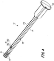
- Fig. 4 is a perspective view illustrating the plunger member 12.
- the plunger member 12 includes the gasket 31, the plunger body 34 that presses the gasket 31, an operation portion 35, a plunger-side engaging portion 36, and a plunger-side retaining portion 38.
- the gasket 31 is formed in a substantially columnar shape.
- One end portion of the gasket 31 is formed in a tapered shape whose diameter continuously decreases toward a distal end.
- This tapered shape corresponds to a shape of an inner surface at the distal end portion of the body portion 21. Therefore, when the gasket 31 is moved toward the distal end portion of the body portion 21, the one end portion of the gasket 31 contacts the inner surface of the distal end portion of the body portion 21 so as not to generate a gap.
- a connecting hole 31a is formed at the other end portion of the gasket 31 as illustrated in Fig. 2 .
- a connecting portion 34a of the plunger body 34 is inserted into the connecting hole 31a so that the gasket 31 and the plunger body 34 are connected.
- two peak portions 32 and 32 are provided on an outer peripheral surface of the gasket 31.
- the two peak portions 32 and 32 are convex portions protruding in a ring shape from the outer peripheral surface of the gasket 31.
- the two peak portions 32 and 32 are provided with a gap therebetween in the axial direction of the gasket 31.
- a material of the gasket 31 is not particularly limited, but it is preferable to use an elastic material in order to obtain favorable liquid tightness with the body portion 21.
- the elastic material may include various rubber materials, such as natural rubber, isobutylene rubber, butyl rubber, and silicone rubber, various thermoplastic elastomers, such as an olefin type and a styrene type, or mixtures thereof.
- the plunger body 34 is formed in a substantially rod shape, and a sectional shape in a direction orthogonal to an axial direction of the plunger body 34 is formed in a substantially cross shape. Further, the plunger body 34 is constituted by four plunger pieces 34b protruding in a direction orthogonal to the axial direction. The four plunger pieces 34b are continuous to be substantially vertical to each other.
- the plunger body 34 is opposed to the opening 24a of the syringe 11 in the state of being held by the temporary holding portion 51 to be described later in the state before performing the sterilization treatment. After performing the sterilization treatment, the plunger body 34 is inserted into the body portion 21 from the opening 24a of the syringe 11 at the time of use, and the most thereof is arranged inside the body portion 21 of the syringe 11 (see Fig. 8 ).
- the connecting portion 34a is provided at the distal end portion of the plunger body 34.
- the connecting portion 34a is inserted into the connecting hole 31a of the gasket 31 and is connected to the gasket 31.
- the gasket 31 is attached to the distal end portion of the plunger body 34.
- the operation portion 35 is provided at a proximal end portion of the plunger body 34.
- the operation portion 35 is formed in a substantially disc shape.
- the gasket 31 arranged at the distal end of the plunger body 34 moves inside the cylindrical hole 21a of the body portion 21 of the syringe 11.
- the plunger-side engaging portion 36 and the plunger-side retaining portion 38 are provided on a shaft portion of the plunger body 34.
- the plunger-side engaging portion 36 is provided on a distal end side in the axial direction of the plunger body 34.
- the plunger-side engaging portion 36 is provided between two plunger pieces 34b and 34b adjacent to each other among the four plunger pieces 34b of the plunger body 34 formed in the cross shape.
- the plunger-side engaging portion 36 is provided at two places symmetric with each other in a direction orthogonal to the axial direction of the plunger body 34 with an axial center of the plunger body 34 interposed between the two places.
- the plunger-side engaging portion 36 has a first engaging portion 36a and a second engaging portion 36b.
- the first engaging portion 36a and the second engaging portion 36b are arranged with a predetermined gap therebetween in the axial direction of the plunger body 34.
- the first engaging portion 36a is arranged to be closer to the distal end side in the axial direction of the plunger body 34 than the second engaging portion 36b.
- the plunger-side retaining portion 38 is provided to be closer to a proximal end side in the axial direction of the plunger body 34 than the plunger-side engaging portion 36.
- the plunger-side retaining portion 38 is formed between two plunger pieces 34b and 34b. which are different from a space between the two plunger pieces 34b and 34b where the plunger-side engaging portion 36 is provided among the four plunger pieces 34b of the plunger body 34.
- the syringe holder 13 has a barrel body portion 41, a through-hole 42, a viewing window 46, a locking hole 47, and a holder collar 48.
- the barrel body portion 41 is formed in a substantially cylindrical shape and covers outer peripheral surfaces of the body portion 21 and the flange portion 24 of the syringe 11 and an outer peripheral surface of the luer lock portion 26.
- the barrel body portion 41 is configured to be grippable by a user.
- a holder opening 41a into which the syringe 11 and the plunger member 12 can be inserted is formed at a proximal end portion of the barrel body portion 41.
- the holder opening 41a is positioned to be closer to the distal end side, which is the proximal end portion of the plunger body 34 inserted into the syringe holder 13, than the operation portion 35. Incidentally, it suffices that the barrel body portion 41 covers at least the outer peripheral surface of the flange portion 24.
- the viewing window 46 is opened at a distal end portion of the barrel body portion 41.
- the viewing window 46 is provided at a position where the liquid chamber formed in the body portion 21 of the syringe 11 is visible from the outside of the syringe holder 13 when the syringe 11 is attached to the syringe holder 13. Accordingly, it is possible to secure the visibility of the interior even if the syringe holder 13 is attached to the syringe 11.
- the holder collar 48 is provided at the proximal end portion of the barrel body portion 41.
- the holder collar 48 protrudes to be substantially vertical from a part of the outer peripheral surface of the barrel body portion 41. Since the holder collar 48 is provided, it is possible to prevent a finger gripping the syringe holder 13 from slipping toward the proximal end direction when the user grips the syringe holder 13 and administers the drug solution. In addition, it is also possible to prevent the drug-solution administration device 1 from rolling when placing the drug-solution administration device 1 on a desk or the like.
- the through-hole 42 and the locking hole 47 are opened in the barrel body portion 41.
- the through-hole 42 and the locking hole 47 are formed to be closer to the proximal end portion side in the axial direction of the barrel body portion 41 than the viewing window 46.
- the flange portion 24 of the syringe 11 is locked by the through-hole 42. As a result, the syringe 11 is held inside the barrel body portion 41.
- the locking hole 47 is formed in the vicinity of the through-hole 42 to be closer to the proximal end portion side in the axial direction of the barrel body portion 41 than the through-hole 42.
- the locking hole 47 is formed to be closer to the proximal end side in the axial direction of the barrel body portion 41 than the flange portion 24 of the syringe 11 held by the barrel body portion 41.
- a locking portion of the temporary holding portion 51 is locked by the locking hole 47.
- Fig. 5 is a perspective view illustrating the temporary holding portion 51.
- Fig. 6 is a perspective view illustrating the temporary holding portion 51 and the plunger member 12.
- the temporary holding portion 51 includes a cylindrical body 52, two holding-portion-side engaging portions 53 and 53, two holding-portion-side retaining portions 54 and 54, a plurality of support ribs 55, and a locking portion 56.
- the cylindrical body 52 is formed in a cylindrical shape. One axial end of the cylindrical body 52 is open.
- the two holding-portion-side engaging portions 53 and 53 and two holding-portion-side retaining portions 54 and 54 are provided on the other axial end portion of the cylindrical body 52.
- the two holding-portion-side engaging portions 53 and 53 are arranged at positions opposed to each other at an edge portion of an opening formed at the other end portion of the cylindrical body 52.
- the two holding-portion-side engaging portions 53 and 53 are bent to be substantially vertical from the edge portion of the cylindrical body 52 toward the inside of a cylindrical hole of the cylindrical body 52.
- the holding-portion-side engaging portion 53 is releasably engaged with the plunger-side engaging portion 36 provided on the plunger body 34. That is, the holding-portion-side engaging portion 53 is arranged between the first engaging portion 36a and the second engaging portion 36b of the plunger-side engaging portion 36. Then, the first engaging portion 36a is engaged with the holding-portion-side engaging portion 53 from the distal end side, and the second engaging portion 36b is engaged with the holding-portion-side engaging portion 53 from the proximal end side Match. As a result, the plunger member 12 is temporarily held by the temporary holding portion 51 in a releasable manner.
- the two holding-portion-side retaining portions 54 and 54 illustrating one example of a retaining portion are formed at the edge portion of the opening formed at the other end portion of the cylindrical body 52 between the two holding-portion-side engaging portions 53 and 53.
- the two holding-portion-side retaining portions 54 and 54 are arranged at positions opposed to each other.
- the two holding-portion-side retaining portions 54 and 54 are bent to be substantially vertical from the edge portion of the cylindrical body 52 toward the inside of the cylindrical hole of the cylindrical body 52. Then, insertion holes through which the plunger body 34 is inserted are formed by distal end portions of the two holding-portion-side engaging portions 53 and 53 and the two holding-portion-side retaining portions 54 and 54.
- the present invention is not limited thereto, and the retaining portion and the temporary holding portion 51 may be formed using different members.
- the plurality of support ribs 55 (four in the present embodiment) illustrating one example of a support portion are formed between the holding-portion-side engaging portion 53 and the holding-portion-side retaining portion 54.
- the plurality of support ribs 55 protrude from an inner wall of the cylindrical body 52 toward the inside of the cylindrical hole with a predetermined length.
- the plurality of support ribs 55 extend from the other end portion of the cylindrical body 52 to a midway portion in the axial direction.
- the plunger body 34 when the plunger body 34 is inserted into the temporary holding portion 51, the plurality of support ribs 55 contacts the plunger piece 34b of the plunger body 34. Therefore, the plunger body 34 is held by the plurality of support ribs 55. Thereby, the plunger member 12 can be held by the temporary holding portion 51 without rattling.
- the gasket 31 is covered by the cylindrical body 52 of the temporary holding portion 51 in the state before performing sterilization treatment as illustrated in Figs. 3 and 6 . As a result, it is possible to prevent the user's finger from contacting the gasket 31, and it is possible to prevent the gasket 31 that has been subjected to the sterilization treatment from being contaminated.
- the locking portion 56 is provided at the distal end portion on an outer peripheral surface of the cylindrical body 52 as illustrated in Fig. 5 .
- the locking portion 56 protrudes outward from the outer peripheral surface of the cylindrical body 52.
- the locking portion 56 is locked by the locking hole 47 of the syringe holder 13 when the cylindrical body 52 is inserted into the cylindrical hole of the barrel body portion 41 of the syringe holder 13.
- the temporary holding portion 51 is opposed to the flange portion 24 of the syringe 11 as illustrated in Figs. 2 and 3 . Further, the plunger member 12 is temporarily held by the temporary holding portion 51 in a state where the gasket 31 is opposed to the opening 24a of the syringe 11 with a gap between the gasket 31 and the opening 24a.
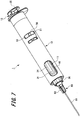
- Fig. 7 is a perspective view illustrating the drug-solution administration device 1 at the time of sucking the drug solution
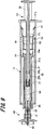
- Fig. 8 is a cross-sectional view illustrating the drug-solution administration device 1 after the sterilization treatment.
- Fig. 9 is a cross-sectional view illustrating a state after sucking the drug solution
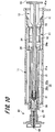
- Fig. 10 is a cross-sectional view illustrating a state after administering the drug solution.
- the syringe 11 is attached to the syringe holder 13 as illustrated in Figs. 1 and 2 .
- the plunger body 34 is inserted in the insertion hole formed at the distal end portions of the two holding-portion-side engaging portions 53 and 53 and the two holding-portion-side retaining portions 54 and 54 in the temporary holding portion 51 as illustrated in Fig. 6 .
- the plunger-side engaging portion 36 is engaged with the holding-portion-side engaging portion 53 of the temporary holding portion 51.
- the gasket 31 is connected to the connecting portion 34a (see Fig. 2 ) of the plunger body 34.
- the gasket 31 is covered by the cylindrical body 52 of the temporary holding portion 51, and the plunger member 12 is temporarily held by the temporary holding portion 51.
- the temporary holding portion 51 and the plunger member 12 are inserted into the cylindrical hole of the barrel body portion 41 of the syringe holder 13. Then, the locking portion 56 of the temporary holding portion 51 is locked by the locking hole 47 of the syringe holder 13 as illustrated in Figs. 1 and 3 . As a result, the plunger member 12 is temporarily held by the temporary holding portion 51 in a state where the gasket 31 is opposed to the opening 24a of the syringe 11.
- the sterilization treatment is performed using high-temperature steam or gases such as high-pressure steam sterilization (autoclave) and ethylene oxide gas (EOG) sterilization.
- the gasket 31 is not inserted into the cylindrical hole 21a of the syringe 11, and is arranged outside the syringe 11.
- a space between the two peak portions 32 of the gasket 31 is opened.
- a plurality of gaps is formed in the cylindrical body 52 of the temporary holding portion 51 at the distal end portion in the axial direction, between the holding-portion-side engaging portion 53 and the support rib 55, between the support rib 55 and the holding-portion-side retaining portion 54, and the like.
- the drug-solution administration device 1 may be wrapped in a state where the gasket 31 is opposed to the opening 24a of the syringe 11, or the drug-solution administration device 1 may be wrapped after inserting the gasket 31 into the cylindrical hole 21a of the syringe 11 to be described later.
- the plunger member 12 is operated to insert the gasket 31 into the cylindrical hole 21a of the syringe 11 at the time of wrapping the drug-solution administration device 1 or at the time of using the drug-solution administration device 1 as illustrated in Figs. 7 and 8 .
- FIG. 7 illustrates an example in which an injection needle assembly 80 having a suction needle tube 81 configured to suck a drug solution from a vial containing the drug solution is attached to the syringe 11 in order to fill the liquid chamber of the syringe 11 with the drug solution.
- the needle hub 82 of the injection needle assembly 80 is screwed into the luer lock portion 26 of the syringe 11.
- the cylindrical hole 21a of the syringe 11 and the suction needle tube 81 of the injection needle assembly 80 communicate with each other via the discharge portion 22.
- the injection needle assembly 80 illustrated in Fig. 7 may be attached to the syringe 11 after inserting the gasket 31 into the cylindrical hole 21a of the syringe 11 as illustrated in Fig. 8 .
- the gasket 31 may be inserted into the cylindrical hole 21a of the syringe 11 after the injection needle assembly 80 illustrated in Fig. 7 is attached to the syringe 11.
- the plunger-side retaining portion 38 climbs over the holding-portion-side retaining portion 54 to move toward the distal end side of the holding-portion-side retaining portion 54. Then, the plunger-side retaining portion 38 can abut on the holding-portion-side retaining portion 54 from the distal end portion side. As a result, it is possible to prevent the plunger member 12 from falling out of the temporary holding portion 51 that has been attached to the syringe holder 13. At this time, a distal end surface of the gasket 31 is spaced apart from the distal end surface of the cylindrical hole 22a of the body portion 21.
- the suction needle tube 81 of the injection needle assembly 80 pierces through the vial, and the plunger member 12 is pulled toward the proximal end of the syringe 11.
- the drug solution M1 is sucked through the suction needle tube 81 of the injection needle assembly 80 so that the liquid chamber of the syringe 11 is filled with the drug solution M1.
- the injection needle assembly 80 is removed from the luer lock portion 26.
- the injection needle assembly 90 having an administration needle tube 91 for piercing the living body is attached to the syringe 11 as illustrated in Fig. 9 . That is, the needle hub 92 of the injection needle assembly 90 is screwed into the luer lock portion 26 of the syringe 11 as illustrated in Fig. 9 . As a result, the administration needle tube 91 of the injection needle assembly 90 communicates with the cylindrical hole 21a of the syringe 11 via the discharge portion 22.
- the administration needle tube 91 pierces through the user's skin.
- the gasket 31 is slidably moved toward the distal end portion of the syringe 11 by operating the plunger member 12.
- the drug solution M1 filling the liquid chamber of the syringe 11 is pushed out of the administration needle tube 91 by the gasket 31.
- the administration of the drug solution to the living body using the drug-solution administration device 1 is completed.
- the embodiment of the present invention has been described including the operational effects thereof.
- the drug-solution administration device of the present invention is not limited to the above-described embodiment, and various modifications can be made within a scope not departing from a gist of the invention described in the claims.
- various other administration parts such as a needle-free syringe having no needle tube and an intranasal administration device for administering a drug solution to a nasal cavity or the like can be applied as an administration part to be attached to the drug-solution administration device 1 as long as the part is attached by screwing.
- a male screw portion may be provided in the discharge portion 22 to be screwed with a female screw portion provided in the administrate part.
- the temporary holding portion 51 and the syringe holder 13 may be integrally molded, or the syringe holder 13 is not necessarily provided.
- the temporary holding portion may be releasably attached to the flange portion or the like of the syringe, or the temporary holding portion may be fixed to the syringe by adhesion or welding.
- the temporary holding portion and the syringe may be integrally molded.
- the gasket 31 is covered by the cylindrical body 52 of the temporary holding portion 51 until the insertion of the gasket 31 into the syringe 11 after the sterilization treatment.
- the syringe holder 13 is not provided, it is possible to prevent the finger of the user from contacting the gasket 31.
- the plunger body of the plunger member and the cylinder body of the temporary holding portion may be fixed by ultrasonic welding or laser welding so as to temporarily hold the plunger member by the temporary holding portion.
- a fixing strength between the plunger body and the cylindrical body is set to a strength at which the plunger body and the cylindrical body are broken when the plunger member is pressed after the sterilization treatment.
- the temporary holding portion and the plunger member may be integrally molded by providing a thin portion which is broken when the plunger member is pressed.
Landscapes
- Health & Medical Sciences (AREA)
- Vascular Medicine (AREA)
- Engineering & Computer Science (AREA)
- Anesthesiology (AREA)
- Biomedical Technology (AREA)
- Heart & Thoracic Surgery (AREA)
- Hematology (AREA)
- Life Sciences & Earth Sciences (AREA)
- Animal Behavior & Ethology (AREA)
- General Health & Medical Sciences (AREA)
- Public Health (AREA)
- Veterinary Medicine (AREA)
- Infusion, Injection, And Reservoir Apparatuses (AREA)
Abstract
Description
- The present invention relates to a drug-solution administration device including a syringe that can be filled with a drug solution and a gasket slidably inserted into the syringe, a method of using the drug-solution administration device, and a method of manufacturing the drug-solution administration device.
- In general, a drug-solution administration device includes: a syringe that can be filled with a drug solution; a gasket slidably inserted into the syringe; and a plunger member that pushes the gasket (see, for example, Patent Literature 1).
- In addition, it is necessary to execute sterilization treatment on the syringe and the gasket. In recent years, radiation sterilization such as gamma rays and electron radiation has been performed as a method of the sterilization treatment. Incidentally, there is a risk that the gasket may deteriorate in the radiation sterilization so that there is a demand for a sterilization method using high-temperature steam or gases such as high-pressure steam sterilization (autoclave) and ethylene oxide gas (EOG) sterilization.
- Patent Literature 1:
JP 2011-212185 A - However, the steam or gases for sterilization hardly reaches an inner wall of the syringe in close contact with the gasket and a space surrounded by two peak portions formed in the gasket and the inner wall of the syringe so that there is a risk that the syringe and gasket are not sufficiently sterilized. Thus, conventionally, when sterilizing the syringe using the high-temperature steam or gases, it is necessary to separately sterilize the syringe and the gasket and then to assemble the syringe and the gasket as a drug-solution administration device.
- The present invention has been made in view of the above problems, and an object thereof is to provide a drug-solution administration device, a method of using a drug-solution administration device, and a method of manufacturing a drug-solution administration device capable of reliably perform sterilization using steam or gases in a state where a syringe and a gasket are assembled in advance as the drug-solution administration device.
- In order to solve the above-described problems and achieve the object of the present invention, a drug-solution administration device of the present invention comprises a syringe, a gasket, a plunger member, and a temporary holding portion. The syringe includes a cylindrical body portion configured to be filled with a drug solution therein, a discharge portion formed at a distal end portion of the body portion, and an opening formed at a proximal end portion of the body portion. The gasket is configured to be slidable inside a cylindrical hole of the body portion. The plunger member includes a plunger body to which the gasket is attached. The temporary holding portion holds the plunger member releasably in a state where the opening of the body portion and a distal end surface of the gasket are opposed to each other with a gap therebetween.
- In addition, a method of using a drug-solution administration device of the present invention is a method of using the drug-solution administration device comprising the above-described configuration, and includes steps illustrated in the following (1) to (4).
- (1) A step of pressing the plunger member toward a distal end of the syringe and releasing holding of the plunger member by the temporary holding portion.
- (2) A step of further pressing the plunger member toward the distal end of the syringe to insert the gasket into the cylindrical hole of the body portion, and causing the distal end surface of the gasket to abut on a distal end surface of the cylindrical hole in the body portion.
- (3) A step of filling a drug solution in the cylindrical hole of the body portion by pulling the plunger member toward a proximal end of the syringe.
- (4) A step of pressing the plunger member toward the distal end of the syringe again to discharge the drug solution from the discharge portion.
- In addition, a method of manufacturing a drug-solution administration device of the present invention is a method of manufacturing the drug-solution administration device comprising the above-described configuration, and includes steps illustrated in the following (1) to (3).
- (1) A step of attaching the gasket to the plunger body of the plunger member.
- (2) A step of holding the plunger member by the temporary holding portion in a state where the opening formed at the proximal end portion of the body portion of the syringe and the distal end surface of the gasket are opposed to each other with a gap therebetween.
- (3) A step of sterilizing the syringe, the gasket, the plunger member, and the temporary holding portion with a sterilization gas or high-pressure steam in a state where the plunger member is held by the temporary holding portion.
- According to the drug-solution administration device, the method of using the drug-solution administration device, and the method of manufacturing the drug-solution administration device of the present invention, it is possible to reliably perform sterilization in the state where the syringe and the gasket are assembled in advance as the drug-solution administration device when performing the sterilization treatment using steam or gases.
-
-
Fig. 1 is a perspective view illustrating a drug-solution administration device according to an embodiment of the present invention. -
Fig. 2 is a cross-sectional view illustrating the drug-solution administration device according to the embodiment of the present invention. -
Fig. 3 is an explanatory view illustrating states of a plunger member and a gasket before sterilization treatment in the drug-solution administration device according to the embodiment of the present invention. -
Fig. 4 is a perspective view illustrating the plunger member and the gasket of the drug-solution administration device according to the embodiment of the present invention. -
Fig. 5 is a perspective view illustrating a temporary holding portion of the drug-solution administration device according to the embodiment of the present invention. -
Fig. 6 is an explanatory view illustrating the plunger member and the temporary holding portion before sterilization treatment in the drug-solution administration device according to the embodiment of the present invention. -
Fig. 7 is a perspective view illustrating a state at the time of sucking a drug solution in the drug-solution administration device according to the embodiment of the present invention. -
Fig. 8 is a cross-sectional view illustrating a state after the sterilization treatment in the drug-solution administration device according to the embodiment of the present invention. -
Fig. 9 is a cross-sectional view illustrating a state where the drug solution has been sucked in the drug-solution administration device according to the embodiment of the present invention. -
Fig. 10 is a cross-sectional view illustrating a state after administration of the drug solution in the drug-solution administration device according to an embodiment of the present invention. - Hereinafter, an embodiment of a drug-solution administration device, and a use method and a manufacturing method of the same of the present invention will be described with reference to
Figs. 1 to 10 . Common members are denoted by identical reference signs throughout the drawings. In addition, the present invention is not limited to the following embodiment. - First, a configuration of an embodiment (hereinafter referred to as "the present embodiment") of the drug-solution administration device of the present invention will be described with reference to
Figs. 1 to 6 . -
Fig. 1 is a perspective view illustrating the drug-solution administration device according to the present embodiment.Fig. 2 is a cross-sectional view illustrating administration parts of the drug-solution administration device of the present embodiment.Fig. 3 is an explanatory view illustrating states of a plunger member, a gasket, and a syringe of the present embodiment. - As illustrated in
Fig. 1 , a drug-solution administration device 1 includes asyringe 11, aplunger member 12, asyringe holder 13 that holds thesyringe 11, and atemporary holding portion 51 that temporarily holds the plunger member. - The
syringe 11 is a syringe filled with a drug solution M1 to be described later. Thesyringe 11 has abody portion 21 formed in a substantially cylindrical shape and adischarge portion 22 formed at a distal end portion of thebody portion 21. - A
gasket 31 to be described later is slidably inserted into thecylindrical hole 21a of thebody portion 21. When thegasket 31 is inserted into thecylindrical hole 21a, a space of thebody portion 21 closer to thedischarge portion 22 than thegasket 31 and a space inside thedischarge portion 22 form a liquid chamber to be filled with the drug solution M1. - Examples of the drug solution M1 may include various vaccines to prevent various infectious diseases, such as influenza, but the drug solution is not limited to the vaccine. Examples of drug solutions M1 other than the vaccine may include a sugar injection solution like glucose, an injection solution for correction of electrolyte, such as sodium chloride or potassium lactate, vitamins, antibiotic infusion solutions, contrast media, steroids, protease inhibitors, fat emulsions, anticancer agents, anesthetic, heparin calcium, antibody preparations, and the like.
- Further, a
flange portion 24 is provided at a proximal end portion of thebody portion 21. Theflange portion 24 protrudes radially outward from an outer peripheral surface of the proximal end portion of thebody portion 21. Theflange portion 24 is engaged with a through-hole 42 provided in thesyringe holder 13 to be described later. As a result, thesyringe 11 is held by thesyringe holder 13. - In addition, an opening 24a communicating with the
cylindrical hole 21a of thebody portion 21 is formed in theflange portion 24. The opening 24a is open in a circular shape. Theopening 24a is opposed to thegasket 31 to be described later in the state before performing the sterilization treatment as illustrated inFigs. 2 and3 . In addition, thegasket 31 and aplunger body 34, which will be described later, are inserted into theopening 24a at the time of use. - The
discharge portion 22 is continuous with one end of thebody portion 21 and formed in a substantially cylindrical shape coaxial with thebody portion 21. Thedischarge portion 22 is formed in a tapered shape whose diameter continuously decreases toward a distal end opposite to thebody portion 21. Acylindrical hole 22a of thedischarge portion 22 communicates with thecylindrical hole 21a of thebody portion 21. - A
luer lock portion 26, which is an example of a screw portion, is joined to thedischarge portion 22. Aneedle hub 82 having asuction needle tube 81 configured to suction a drug solution and a needle hub having a needle tube that can pierce a living body are releasably attached to theluer lock portion 26. - Examples of a material of the
syringe 11 may include various types of resin such as polyvinyl chloride, polyethylene, polypropylene, cyclic polyolefin, polystyrene, poly-(4-methylpentene-1), polycarbonate, acrylic resin, an acrylonitrile-butadiene-styrene copolymer, polyester such as polyethylene terephthalate, a butadiene-styrene copolymer, and polyamide (for example, nylon 6, nylon 6/6, nylon 6/10, and nylon 12). Among them, it is preferable to use resin such as polypropylene, cyclic polyolefin, polyester, and poly-(4-methylpentene-1) from the viewpoint that molding is easy. Incidentally, it is preferable that the material of thesyringe 11 be substantially transparent in order to secure the visibility of the interior. -
Fig. 4 is a perspective view illustrating theplunger member 12. - As illustrated in
Fig. 4 , theplunger member 12 includes thegasket 31, theplunger body 34 that presses thegasket 31, anoperation portion 35, a plunger-side engaging portion 36, and a plunger-side retaining portion 38. - As illustrated in
Fig. 2 , thegasket 31 is formed in a substantially columnar shape. One end portion of thegasket 31 is formed in a tapered shape whose diameter continuously decreases toward a distal end. This tapered shape corresponds to a shape of an inner surface at the distal end portion of thebody portion 21. Therefore, when thegasket 31 is moved toward the distal end portion of thebody portion 21, the one end portion of thegasket 31 contacts the inner surface of the distal end portion of thebody portion 21 so as not to generate a gap. - In addition, a connecting
hole 31a is formed at the other end portion of thegasket 31 as illustrated inFig. 2 . A connectingportion 34a of theplunger body 34 is inserted into the connectinghole 31a so that thegasket 31 and theplunger body 34 are connected. - Further, two
peak portions gasket 31. The twopeak portions gasket 31. The twopeak portions gasket 31. When thegasket 31 is inserted into thecylindrical hole 21a of thesyringe 11, the twopeak portions cylindrical hole 21a. - A material of the
gasket 31 is not particularly limited, but it is preferable to use an elastic material in order to obtain favorable liquid tightness with thebody portion 21. Examples of the elastic material may include various rubber materials, such as natural rubber, isobutylene rubber, butyl rubber, and silicone rubber, various thermoplastic elastomers, such as an olefin type and a styrene type, or mixtures thereof. - The
plunger body 34 is formed in a substantially rod shape, and a sectional shape in a direction orthogonal to an axial direction of theplunger body 34 is formed in a substantially cross shape. Further, theplunger body 34 is constituted by fourplunger pieces 34b protruding in a direction orthogonal to the axial direction. The fourplunger pieces 34b are continuous to be substantially vertical to each other. - As illustrated in
Figs. 2 and3 , theplunger body 34 is opposed to theopening 24a of thesyringe 11 in the state of being held by thetemporary holding portion 51 to be described later in the state before performing the sterilization treatment. After performing the sterilization treatment, theplunger body 34 is inserted into thebody portion 21 from theopening 24a of thesyringe 11 at the time of use, and the most thereof is arranged inside thebody portion 21 of the syringe 11 (seeFig. 8 ). - In addition, the connecting
portion 34a is provided at the distal end portion of theplunger body 34. The connectingportion 34a is inserted into the connectinghole 31a of thegasket 31 and is connected to thegasket 31. As a result, thegasket 31 is attached to the distal end portion of theplunger body 34. - The
operation portion 35 is provided at a proximal end portion of theplunger body 34. Theoperation portion 35 is formed in a substantially disc shape. When theoperation portion 35 is pressed by the user at the time of using the drug-solution administration device 1, thegasket 31 arranged at the distal end of theplunger body 34 moves inside thecylindrical hole 21a of thebody portion 21 of thesyringe 11. - In addition, the plunger-
side engaging portion 36 and the plunger-side retaining portion 38 are provided on a shaft portion of theplunger body 34. The plunger-side engaging portion 36 is provided on a distal end side in the axial direction of theplunger body 34. The plunger-side engaging portion 36 is provided between twoplunger pieces plunger pieces 34b of theplunger body 34 formed in the cross shape. Further, the plunger-side engaging portion 36 is provided at two places symmetric with each other in a direction orthogonal to the axial direction of theplunger body 34 with an axial center of theplunger body 34 interposed between the two places. - In addition, the plunger-
side engaging portion 36 has a firstengaging portion 36a and a secondengaging portion 36b. The firstengaging portion 36a and the secondengaging portion 36b are arranged with a predetermined gap therebetween in the axial direction of theplunger body 34. The firstengaging portion 36a is arranged to be closer to the distal end side in the axial direction of theplunger body 34 than the secondengaging portion 36b. - The plunger-
side retaining portion 38 is provided to be closer to a proximal end side in the axial direction of theplunger body 34 than the plunger-side engaging portion 36. The plunger-side retaining portion 38 is formed between twoplunger pieces 34b and 34b. which are different from a space between the twoplunger pieces side engaging portion 36 is provided among the fourplunger pieces 34b of theplunger body 34. - As illustrated in
Figs. 1 and2 , thesyringe holder 13 has abarrel body portion 41, a through-hole 42, aviewing window 46, a lockinghole 47, and aholder collar 48. - The
barrel body portion 41 is formed in a substantially cylindrical shape and covers outer peripheral surfaces of thebody portion 21 and theflange portion 24 of thesyringe 11 and an outer peripheral surface of theluer lock portion 26. Thebarrel body portion 41 is configured to be grippable by a user. Aholder opening 41a into which thesyringe 11 and theplunger member 12 can be inserted is formed at a proximal end portion of thebarrel body portion 41. - The
holder opening 41a is positioned to be closer to the distal end side, which is the proximal end portion of theplunger body 34 inserted into thesyringe holder 13, than theoperation portion 35. Incidentally, it suffices that thebarrel body portion 41 covers at least the outer peripheral surface of theflange portion 24. - The
viewing window 46 is opened at a distal end portion of thebarrel body portion 41. Theviewing window 46 is provided at a position where the liquid chamber formed in thebody portion 21 of thesyringe 11 is visible from the outside of thesyringe holder 13 when thesyringe 11 is attached to thesyringe holder 13. Accordingly, it is possible to secure the visibility of the interior even if thesyringe holder 13 is attached to thesyringe 11. - Further, the
holder collar 48 is provided at the proximal end portion of thebarrel body portion 41. Theholder collar 48 protrudes to be substantially vertical from a part of the outer peripheral surface of thebarrel body portion 41. Since theholder collar 48 is provided, it is possible to prevent a finger gripping thesyringe holder 13 from slipping toward the proximal end direction when the user grips thesyringe holder 13 and administers the drug solution. In addition, it is also possible to prevent the drug-solution administration device 1 from rolling when placing the drug-solution administration device 1 on a desk or the like. - In addition, when the
syringe 11 and theplunger member 12 are inserted into thebarrel body portion 41 from theholder opening 41a, it is possible to determine a direction in which thesyringe 11 and theplunger member 12 are inserted in accordance with a short-diameter portion of theholder collar 48. - In addition, the through-
hole 42 and the lockinghole 47 are opened in thebarrel body portion 41. The through-hole 42 and the lockinghole 47 are formed to be closer to the proximal end portion side in the axial direction of thebarrel body portion 41 than theviewing window 46. Theflange portion 24 of thesyringe 11 is locked by the through-hole 42. As a result, thesyringe 11 is held inside thebarrel body portion 41. - The locking
hole 47 is formed in the vicinity of the through-hole 42 to be closer to the proximal end portion side in the axial direction of thebarrel body portion 41 than the through-hole 42. Thus, the lockinghole 47 is formed to be closer to the proximal end side in the axial direction of thebarrel body portion 41 than theflange portion 24 of thesyringe 11 held by thebarrel body portion 41. A locking portion of thetemporary holding portion 51 is locked by the lockinghole 47. - Next, the
temporary holding portion 51 will be described with reference toFigs. 5 and6 . -
Fig. 5 is a perspective view illustrating thetemporary holding portion 51.Fig. 6 is a perspective view illustrating thetemporary holding portion 51 and theplunger member 12. - As illustrated in
Fig. 5 , thetemporary holding portion 51 includes acylindrical body 52, two holding-portion-side engaging portions side retaining portions support ribs 55, and a lockingportion 56. Thecylindrical body 52 is formed in a cylindrical shape. One axial end of thecylindrical body 52 is open. In addition, the two holding-portion-side engaging portions side retaining portions cylindrical body 52. - The two holding-portion-
side engaging portions cylindrical body 52. The two holding-portion-side engaging portions cylindrical body 52 toward the inside of a cylindrical hole of thecylindrical body 52. - As illustrated in
Figs. 2 and6 , the holding-portion-side engaging portion 53 is releasably engaged with the plunger-side engaging portion 36 provided on theplunger body 34. That is, the holding-portion-side engaging portion 53 is arranged between the first engagingportion 36a and the secondengaging portion 36b of the plunger-side engaging portion 36. Then, the first engagingportion 36a is engaged with the holding-portion-side engaging portion 53 from the distal end side, and the secondengaging portion 36b is engaged with the holding-portion-side engaging portion 53 from the proximal end side Match. As a result, theplunger member 12 is temporarily held by thetemporary holding portion 51 in a releasable manner. - The two holding-portion-
side retaining portions cylindrical body 52 between the two holding-portion-side engaging portions side retaining portions side retaining portions cylindrical body 52 toward the inside of the cylindrical hole of thecylindrical body 52. Then, insertion holes through which theplunger body 34 is inserted are formed by distal end portions of the two holding-portion-side engaging portions side retaining portions - Although the example in which the retaining portion is provided in the
temporary holding portion 51 has been described in this example, the present invention is not limited thereto, and the retaining portion and thetemporary holding portion 51 may be formed using different members. - The plurality of support ribs 55 (four in the present embodiment) illustrating one example of a support portion are formed between the holding-portion-
side engaging portion 53 and the holding-portion-side retaining portion 54. The plurality ofsupport ribs 55 protrude from an inner wall of thecylindrical body 52 toward the inside of the cylindrical hole with a predetermined length. In addition, the plurality ofsupport ribs 55 extend from the other end portion of thecylindrical body 52 to a midway portion in the axial direction. - As illustrated in
Fig. 6 , when theplunger body 34 is inserted into thetemporary holding portion 51, the plurality ofsupport ribs 55 contacts theplunger piece 34b of theplunger body 34. Therefore, theplunger body 34 is held by the plurality ofsupport ribs 55. Thereby, theplunger member 12 can be held by thetemporary holding portion 51 without rattling. In addition, thegasket 31 is covered by thecylindrical body 52 of thetemporary holding portion 51 in the state before performing sterilization treatment as illustrated inFigs. 3 and6 . As a result, it is possible to prevent the user's finger from contacting thegasket 31, and it is possible to prevent thegasket 31 that has been subjected to the sterilization treatment from being contaminated. - In addition, the locking
portion 56 is provided at the distal end portion on an outer peripheral surface of thecylindrical body 52 as illustrated inFig. 5 . The lockingportion 56 protrudes outward from the outer peripheral surface of thecylindrical body 52. As illustrated inFigs. 1 and3 , the lockingportion 56 is locked by the lockinghole 47 of thesyringe holder 13 when thecylindrical body 52 is inserted into the cylindrical hole of thebarrel body portion 41 of thesyringe holder 13. - Thus, the
temporary holding portion 51 is opposed to theflange portion 24 of thesyringe 11 as illustrated inFigs. 2 and3 . Further, theplunger member 12 is temporarily held by thetemporary holding portion 51 in a state where thegasket 31 is opposed to theopening 24a of thesyringe 11 with a gap between thegasket 31 and theopening 24a. - Next, a manufacturing method and a use method of the drug-solution administration device 1 having the above-described configuration will be described with reference to
Figs. 1 to 10 . -
Fig. 7 is a perspective view illustrating the drug-solution administration device 1 at the time of sucking the drug solution, andFig. 8 is a cross-sectional view illustrating the drug-solution administration device 1 after the sterilization treatment.Fig. 9 is a cross-sectional view illustrating a state after sucking the drug solution, andFig. 10 is a cross-sectional view illustrating a state after administering the drug solution. - First, the
syringe 11 is attached to thesyringe holder 13 as illustrated inFigs. 1 and2 . Next, theplunger body 34 is inserted in the insertion hole formed at the distal end portions of the two holding-portion-side engaging portions side retaining portions temporary holding portion 51 as illustrated inFig. 6 . Then, the plunger-side engaging portion 36 is engaged with the holding-portion-side engaging portion 53 of thetemporary holding portion 51. In addition, thegasket 31 is connected to the connectingportion 34a (seeFig. 2 ) of theplunger body 34. As a result, thegasket 31 is covered by thecylindrical body 52 of thetemporary holding portion 51, and theplunger member 12 is temporarily held by thetemporary holding portion 51. - Next, the
temporary holding portion 51 and theplunger member 12 are inserted into the cylindrical hole of thebarrel body portion 41 of thesyringe holder 13. Then, the lockingportion 56 of thetemporary holding portion 51 is locked by the lockinghole 47 of thesyringe holder 13 as illustrated inFigs. 1 and3 . As a result, theplunger member 12 is temporarily held by thetemporary holding portion 51 in a state where thegasket 31 is opposed to theopening 24a of thesyringe 11. - Next, the sterilization treatment is performed using high-temperature steam or gases such as high-pressure steam sterilization (autoclave) and ethylene oxide gas (EOG) sterilization. Here, the
gasket 31 is not inserted into thecylindrical hole 21a of thesyringe 11, and is arranged outside thesyringe 11. Thus, a space between the twopeak portions 32 of thegasket 31 is opened. In addition, a plurality of gaps is formed in thecylindrical body 52 of thetemporary holding portion 51 at the distal end portion in the axial direction, between the holding-portion-side engaging portion 53 and thesupport rib 55, between thesupport rib 55 and the holding-portion-side retaining portion 54, and the like. - As a result, it is possible to cause the steam or gases to spread up to the
gasket 31 attached to theplunger member 12 temporarily held by thetemporary holding portion 51 and to the inside of thecylindrical hole 21a of thesyringe 11. As a result, it is possible to reliably sterilize thegasket 31 and thesyringe 11 as the whole in the state of being assembled in advance as the drug-solution administration device 1. With the above-described processing, the manufacturing method of the drug-solution administration device 1 is completed. Incidentally, the drug-solution administration device 1 may be wrapped in a state where thegasket 31 is opposed to theopening 24a of thesyringe 11, or the drug-solution administration device 1 may be wrapped after inserting thegasket 31 into thecylindrical hole 21a of thesyringe 11 to be described later. - When the sterilization treatment is completed, the
plunger member 12 is operated to insert thegasket 31 into thecylindrical hole 21a of thesyringe 11 at the time of wrapping the drug-solution administration device 1 or at the time of using the drug-solution administration device 1 as illustrated inFigs. 7 and8 . - The example illustrated in
Fig. 7 illustrates an example in which aninjection needle assembly 80 having asuction needle tube 81 configured to suck a drug solution from a vial containing the drug solution is attached to thesyringe 11 in order to fill the liquid chamber of thesyringe 11 with the drug solution. Theneedle hub 82 of theinjection needle assembly 80 is screwed into theluer lock portion 26 of thesyringe 11. As a result, thecylindrical hole 21a of thesyringe 11 and thesuction needle tube 81 of theinjection needle assembly 80 communicate with each other via thedischarge portion 22. - Incidentally, the
injection needle assembly 80 illustrated inFig. 7 may be attached to thesyringe 11 after inserting thegasket 31 into thecylindrical hole 21a of thesyringe 11 as illustrated inFig. 8 . In addition, thegasket 31 may be inserted into thecylindrical hole 21a of thesyringe 11 after theinjection needle assembly 80 illustrated inFig. 7 is attached to thesyringe 11. - When the
plunger member 12 is pushed into the distal end portion of thesyringe 11 as illustrated inFigs. 7 and8 , the engagement between the plunger-side engaging portion 36 of theplunger member 12 and the holding-portion-side engaging portion 53 of thetemporary holding portion 51 is released. In addition, the plurality ofsupport ribs 55 of thetemporary holding portion 51 contact theplunger pieces 34b of theplunger body 34 as illustrated inFig. 6 . Thus, theplunger body 34 does not deviates from theopening 24a of thesyringe 11, and theplunger body 34 and thegasket 31 can be inserted straight into thecylindrical hole 21a of thesyringe 11. - In addition, when the
gasket 31 and theplunger body 34 are inserted into thecylindrical hole 21a of thesyringe 11, the plunger-side retaining portion 38 climbs over the holding-portion-side retaining portion 54 to move toward the distal end side of the holding-portion-side retaining portion 54. Then, the plunger-side retaining portion 38 can abut on the holding-portion-side retaining portion 54 from the distal end portion side. As a result, it is possible to prevent theplunger member 12 from falling out of thetemporary holding portion 51 that has been attached to thesyringe holder 13. At this time, a distal end surface of thegasket 31 is spaced apart from the distal end surface of thecylindrical hole 22a of thebody portion 21. - The
suction needle tube 81 of theinjection needle assembly 80 pierces through the vial, and theplunger member 12 is pulled toward the proximal end of thesyringe 11. As a result, the drug solution M1 is sucked through thesuction needle tube 81 of theinjection needle assembly 80 so that the liquid chamber of thesyringe 11 is filled with the drug solution M1. When the filling of the drug solution M1 into the liquid chamber of thesyringe 11 is completed, theinjection needle assembly 80 is removed from theluer lock portion 26. - Then, the
injection needle assembly 90 having anadministration needle tube 91 for piercing the living body is attached to thesyringe 11 as illustrated inFig. 9 . That is, theneedle hub 92 of theinjection needle assembly 90 is screwed into theluer lock portion 26 of thesyringe 11 as illustrated inFig. 9 . As a result, theadministration needle tube 91 of theinjection needle assembly 90 communicates with thecylindrical hole 21a of thesyringe 11 via thedischarge portion 22. - Next, the
administration needle tube 91 pierces through the user's skin. Then, thegasket 31 is slidably moved toward the distal end portion of thesyringe 11 by operating theplunger member 12. As a result, the drug solution M1 filling the liquid chamber of thesyringe 11 is pushed out of theadministration needle tube 91 by thegasket 31. As a result, the administration of the drug solution to the living body using the drug-solution administration device 1 is completed. - As above, the embodiment of the present invention has been described including the operational effects thereof. However, the drug-solution administration device of the present invention is not limited to the above-described embodiment, and various modifications can be made within a scope not departing from a gist of the invention described in the claims.
- Incidentally, various other administration parts such as a needle-free syringe having no needle tube and an intranasal administration device for administering a drug solution to a nasal cavity or the like can be applied as an administration part to be attached to the drug-solution administration device 1 as long as the part is attached by screwing.
- In addition, the example in which the
luer lock portion 26 is provided as the screw portion has been described in the above-described embodiment, but the present invention is not limited thereto. A male screw portion may be provided in thedischarge portion 22 to be screwed with a female screw portion provided in the administrate part. - Further, the example in which the
syringe 11 and thetemporary holding portion 51 are attached to thesyringe holder 13 has been described in the above-described embodiment, but the present invention is not limited thereto. For example, thetemporary holding portion 51 and thesyringe holder 13 may be integrally molded, or thesyringe holder 13 is not necessarily provided. When thesyringe holder 13 is not provided, the temporary holding portion may be releasably attached to the flange portion or the like of the syringe, or the temporary holding portion may be fixed to the syringe by adhesion or welding. Alternatively, the temporary holding portion and the syringe may be integrally molded. - As described above, the
gasket 31 is covered by thecylindrical body 52 of thetemporary holding portion 51 until the insertion of thegasket 31 into thesyringe 11 after the sterilization treatment. Thus, even when thesyringe holder 13 is not provided, it is possible to prevent the finger of the user from contacting thegasket 31. - Further, the example in which the
plunger member 12 is temporarily held by thetemporary holding portion 51 by engaging the plunger-side engaging portion 36 and the holding-portion-side engaging portion 53 has been described, but the present invention is not limited thereto. For example, the plunger body of the plunger member and the cylinder body of the temporary holding portion may be fixed by ultrasonic welding or laser welding so as to temporarily hold the plunger member by the temporary holding portion. Incidentally, a fixing strength between the plunger body and the cylindrical body is set to a strength at which the plunger body and the cylindrical body are broken when the plunger member is pressed after the sterilization treatment. Alternatively, the temporary holding portion and the plunger member may be integrally molded by providing a thin portion which is broken when the plunger member is pressed. -
- 1
- drug-solution administration device
- 11
- syringe
- 12
- plunger member
- 13
- syringe holder
- 21
- body portion
- 21a
- cylindrical hole
- 22
- discharge portion
- 22a
- cylindrical hole
- 24
- flange portion
- 24a
- opening
- 26
- luer lock portion
- 31
- gasket
- 31a
- connecting hole
- 32
- peak portion
- 34
- plunger body
- 34a
- connecting portion
- 34b
- plunger piece
- 35
- operation portion
- 36
- plunger-side engaging portion
- 36a
- first engaging portion
- 36b
- second engaging portion
- 38
- plunger-side retaining portion
- 41
- barrel body portion
- 41a
- holder opening
- 42
- through-hole
- 46
- viewing window
- 47
- locking hole
- 48
- holder collar
- 51
- temporary holding portion
- 52
- barrel body
- 53
- holding-portion-side engaging portion
- 54
- holding-portion-side retaining portion (retaining portion)
- 55
- support rib (support portion)
- 56
- locking portion
- 80, 90
- injection needle assembly
- 81
- suction needle tube
- 82, 92
- needle hub
- 91
- administration needle tube
Claims (10)
- A drug-solution administration device comprising:a syringe that includes a cylindrical body portion configured to be filled with a drug solution therein, a discharge portion formed at a distal end portion of the body portion, and an opening formed at a proximal end portion of the body portion;a gasket slidable inside a cylindrical hole of the body portion;a plunger member including a plunger body to which the gasket is attached; anda temporary holding portion that releasably holds the plunger member in a state in which the opening of the body portion and a distal end surface of the gasket are opposed to each other with a gap therebetween.
- The drug-solution administration device according to claim 1,
wherein holding of the plunger member by the temporary holding portion is releasable as the plunger member is pushed toward a distal end of the syringe. - The drug-solution administration device according to claim 1 or 2,
wherein the plunger body comprises a plunger-side engaging portion,
wherein the temporary holding portion comprises a holding-portion-side engaging portion releasably engaged with the plunger-side engaging portion, and
wherein the plunger member is releasably held by the temporary holding portion by engagement between the plunger-side engaging portion and the holding-portion-side engaging portion. - The drug-solution administration device according to claim 3,
wherein the plunger-side engaging portion comprises a first engaging portion engaged with the holding-portion-side engaging portion from a distal end side and a second engaging portion engaged with the holding-portion-side engaging portion from a proximal end side, and
wherein the plunger member is releasably held by the temporary holding portion as the holding-portion-side engaging portion is positioned between the first engaging portion and the second engaging portion. - The drug-solution administration device according to claim 3 or 4,
wherein the plunger-side engaging portions are provided at two places that are positioned to be opposed to each other with an axial center of the plunger body interposed therebetween, and
wherein the holding-portion-side engaging portions are provided at two places that are positioned to be opposed to each other with an axial center of the body portion interposed therebetween. - The drug-solution administration device according to any one of claims 3 to 5,
wherein the plunger body comprises the plunger-side retaining portion provided at a position proximal of the plunger-side engaging portion and different from the plunger-side engaging portion around the axial center of the plunger body,
wherein drug-solution administration device further comprises a retaining portion that is provided at a position different from the holding-portion-side engaging portion around the axial center of the body portion and that is configured to abut on a plunger-side retaining portion from a proximal end side,
wherein the plunger-side retaining portion and the retaining portion are configured to restrict a movement of the plunger body toward the proximal end side when the plunger-side retaining portion climbs over the retaining portion from the proximal end side and the plunger-side retaining portion and the retaining portion abut on each other, and
wherein the distal end surface of the gasket is spaced apart from a distal end surface of the cylindrical hole in the body portion when the plunger-side retaining portion and the retaining portion abut on each other. - The drug-solution administration device according to any one of claims 1 to 6,
wherein the temporary holding portion comprises a support portion that supports the plunger body, and
wherein an inclination of an axis of the plunger body with respect to an axis of the body portion is restricted by the support portion. - The drug-solution administration device according to any one of claims 1 to 7,
wherein an injection needle assembly, which comprises a needle tube including a needle tip that is configured to pierce a living body, and an injection needle assembly, which comprises a suction needle tube including a needle tip that is configured to suck the drug solution, are detachably mounted to the discharge portion of the syringe,
wherein drug-solution administration device further comprises a syringe holder that holds the syringe, and
wherein the temporary holding portion is provided in the syringe holder. - A method of using a drug-solution administration device that comprises:a syringe that includes a cylindrical body portion configured to be filled with a drug solution therein, a discharge portion formed at a distal end portion of the body portion, and an opening formed at a proximal end portion of the body portion;a gasket slidable inside a cylindrical hole of the body portion;a plunger member including a plunger body to which the gasket is attached; anda temporary holding portion that releasably holds the plunger member in a state in which the opening of the body portion and a distal end surface of the gasket are opposed to each other with a gap therebetween, the method comprising:a step of pressing the plunger member toward a distal end side of the syringe to release holding of the plunger member performed by the temporary holding portion;a step of further pressing the plunger member toward the distal end side of the syringe to insert the gasket into the cylindrical hole of the body portion and to cause the distal end surface of the gasket to abut on a distal end surface of the cylindrical hole in the body portion;a step of pulling the plunger member toward a proximal end side of the syringe to fill an inside of the cylindrical hole of the body portion with the drug solution; anda step of pressing the plunger member again toward the distal end side of the syringe to discharge the drug solution from the discharge portion.
- A method of manufacturing a drug-solution administration device that comprises:a syringe that includes a cylindrical body portion configured to be filled with a drug solution, a discharge portion formed at a distal end portion of the body portion, and an opening formed at a proximal end portion of the body portion;a gasket slidable inside a cylindrical hole of the body portion;a plunger member including a plunger body to which the gasket is attached; anda temporary holding portion that releasably holds the plunger member in a state in which the opening of the body portion and a distal end surface of the gasket are opposed to each other with a gap therebetween, the method comprising:a step of attaching the gasket to the plunger body of the plunger member;a step of holding the plunger member by the temporary holding portion in a state in which the opening formed in the proximal end portion of the body portion of the syringe and the distal end surface of the gasket are opposed to each other with the gap therebetween; anda step of sterilizing the syringe, the gasket, the plunger member, and the temporary holding portion with a sterilization gas or high-pressure steam in a state in which the plunger member is held by the temporary holding portion.
Applications Claiming Priority (2)
| Application Number | Priority Date | Filing Date | Title |
|---|---|---|---|
| JP2016066145 | 2016-03-29 | ||
| PCT/JP2017/012795 WO2017170635A1 (en) | 2016-03-29 | 2017-03-29 | Medicine administering apparatus, method of using medicine administering apparatus, and method for manufacturing medicine administering apparatus |
Publications (3)
| Publication Number | Publication Date |
|---|---|
| EP3437681A1 true EP3437681A1 (en) | 2019-02-06 |
| EP3437681A4 EP3437681A4 (en) | 2019-09-04 |
| EP3437681B1 EP3437681B1 (en) | 2024-04-03 |
Family
ID=59965803
Family Applications (1)
| Application Number | Title | Priority Date | Filing Date |
|---|---|---|---|
| EP17775172.4A Active EP3437681B1 (en) | 2016-03-29 | 2017-03-29 | Medicine administering apparatus, method of using medicine administering apparatus, and method for manufacturing medicine administering apparatus |
Country Status (3)
| Country | Link |
|---|---|
| EP (1) | EP3437681B1 (en) |
| JP (1) | JP6914913B2 (en) |
| WO (1) | WO2017170635A1 (en) |
Families Citing this family (4)
| Publication number | Priority date | Publication date | Assignee | Title |
|---|---|---|---|---|
| EP3698830A4 (en) * | 2017-10-18 | 2021-05-26 | Maeda Industry Co., Ltd. | Mechanism for preventing syringe gasket from slipping out |
| TWI712431B (en) * | 2018-03-19 | 2020-12-11 | 日商前田產業股份有限公司 | Syringe gasket falling off prevention mechanism |
| CN112996550B (en) * | 2018-05-01 | 2023-02-28 | Csp技术公司 | Drug delivery device and method of use and manufacture thereof |
| WO2025088971A1 (en) * | 2023-10-26 | 2025-05-01 | テルモ株式会社 | Drug solution administration device, intermediate assembly of drug solution administration device, method for assembling drug solution administration device, and medical instrument package |
Family Cites Families (6)
| Publication number | Priority date | Publication date | Assignee | Title |
|---|---|---|---|---|
| SE9101261D0 (en) * | 1991-04-25 | 1991-04-25 | Kabi Pharmacia Ab | INJECTION CONTAINER |
| US5785682A (en) * | 1995-03-22 | 1998-07-28 | Abbott Laboratories | Pre-filled syringe drug delivery system |
| JP4152104B2 (en) * | 2001-12-28 | 2008-09-17 | テルモ株式会社 | Syringe and gasket |
| JP2004313369A (en) * | 2003-04-15 | 2004-11-11 | Menicon Co Ltd | Cartridge injector, cartridge and ophthalmic injector set equipped with the injector |
| SE529693C2 (en) * | 2005-03-04 | 2007-10-30 | Millipore Ab | Sterile syringe |
| JP6411097B2 (en) * | 2014-07-03 | 2018-10-24 | テルモ株式会社 | Prefilled syringe |
-
2017
- 2017-03-29 WO PCT/JP2017/012795 patent/WO2017170635A1/en not_active Ceased
- 2017-03-29 EP EP17775172.4A patent/EP3437681B1/en active Active
- 2017-03-29 JP JP2018508122A patent/JP6914913B2/en not_active Expired - Fee Related
Also Published As
| Publication number | Publication date |
|---|---|
| JPWO2017170635A1 (en) | 2019-02-07 |
| EP3437681A4 (en) | 2019-09-04 |
| WO2017170635A1 (en) | 2017-10-05 |
| JP6914913B2 (en) | 2021-08-04 |
| EP3437681B1 (en) | 2024-04-03 |
Similar Documents
| Publication | Publication Date | Title |
|---|---|---|
| AU2016237183B2 (en) | Syringe holder and medical solution administration set | |
| JP5746127B2 (en) | Method and apparatus for delivering a therapeutic agent through an injection port | |
| JP4599345B2 (en) | Drug delivery system and method using the same | |
| US5718690A (en) | Hypodermic injector system and method for maintaining the sterility thereof prior to use | |
| EP3042679B1 (en) | Outer tube for syringe and pre-filled syringe | |
| EP3437681B1 (en) | Medicine administering apparatus, method of using medicine administering apparatus, and method for manufacturing medicine administering apparatus | |
| RU2647441C2 (en) | Assembly comprising an adapter for coupling with a medical container and a blister | |
| EP3127570B1 (en) | Syringe | |
| US20150073353A1 (en) | Sealed self-activating injection device for delivery of medicine from a prefilled cartridge or vial | |
| WO2012039276A1 (en) | Method of assembling medicament injection device | |
| WO2016158627A1 (en) | Assembly for protecting puncture needle, syringe assembly, and method for manufacturing same | |
| CN102858393A (en) | Prefilled Syringe | |
| EP2898912B1 (en) | Drug administration instrument | |
| WO2011068131A1 (en) | Prefilled syringe | |
| JP2011115345A (en) | Prefilled syringe | |
| JP5411729B2 (en) | Drug administration device | |
| JP7113406B2 (en) | needle storage magazine assembly | |
| JP2011212183A (en) | Prefilled syringe | |
| US20180280628A1 (en) | Syringe and needle assembly | |
| JPH10272181A (en) | Syringe and syringe assembly | |
| WO2014061151A1 (en) | Medication delivery device | |
| WO2014033865A1 (en) | Medicine administration device | |
| JP2002078801A (en) | Liquid infusing instrument |
Legal Events
| Date | Code | Title | Description |
|---|---|---|---|
| STAA | Information on the status of an ep patent application or granted ep patent |
Free format text: STATUS: THE INTERNATIONAL PUBLICATION HAS BEEN MADE |
|
| PUAI | Public reference made under article 153(3) epc to a published international application that has entered the european phase |
Free format text: ORIGINAL CODE: 0009012 |
|
| STAA | Information on the status of an ep patent application or granted ep patent |
Free format text: STATUS: REQUEST FOR EXAMINATION WAS MADE |
|
| 17P | Request for examination filed |
Effective date: 20181023 |
|
| AK | Designated contracting states |
Kind code of ref document: A1 Designated state(s): AL AT BE BG CH CY CZ DE DK EE ES FI FR GB GR HR HU IE IS IT LI LT LU LV MC MK MT NL NO PL PT RO RS SE SI SK SM TR |
|
| AX | Request for extension of the european patent |
Extension state: BA ME |
|
| DAV | Request for validation of the european patent (deleted) | ||
| DAX | Request for extension of the european patent (deleted) | ||
| A4 | Supplementary search report drawn up and despatched |
Effective date: 20190807 |
|
| RIC1 | Information provided on ipc code assigned before grant |
Ipc: A61M 5/00 20060101ALI20190801BHEP Ipc: A61M 5/31 20060101ALI20190801BHEP Ipc: A61M 5/315 20060101AFI20190801BHEP |
|
| STAA | Information on the status of an ep patent application or granted ep patent |
Free format text: STATUS: EXAMINATION IS IN PROGRESS |
|
| 17Q | First examination report despatched |
Effective date: 20200818 |
|
| GRAP | Despatch of communication of intention to grant a patent |
Free format text: ORIGINAL CODE: EPIDOSNIGR1 |
|
| STAA | Information on the status of an ep patent application or granted ep patent |
Free format text: STATUS: GRANT OF PATENT IS INTENDED |
|
| INTG | Intention to grant announced |
Effective date: 20231026 |
|
| GRAS | Grant fee paid |
Free format text: ORIGINAL CODE: EPIDOSNIGR3 |
|
| GRAA | (expected) grant |
Free format text: ORIGINAL CODE: 0009210 |
|
| STAA | Information on the status of an ep patent application or granted ep patent |
Free format text: STATUS: THE PATENT HAS BEEN GRANTED |
|
| AK | Designated contracting states |
Kind code of ref document: B1 Designated state(s): AL AT BE BG CH CY CZ DE DK EE ES FI FR GB GR HR HU IE IS IT LI LT LU LV MC MK MT NL NO PL PT RO RS SE SI SK SM TR |
|
| REG | Reference to a national code |
Ref country code: GB Ref legal event code: FG4D |
|
| REG | Reference to a national code |
Ref country code: CH Ref legal event code: EP |
|
| REG | Reference to a national code |
Ref country code: IE Ref legal event code: FG4D |
|
| REG | Reference to a national code |
Ref country code: DE Ref legal event code: R096 Ref document number: 602017080626 Country of ref document: DE |
|
| REG | Reference to a national code |
Ref country code: LT Ref legal event code: MG9D |
|
| REG | Reference to a national code |
Ref country code: NL Ref legal event code: MP Effective date: 20240403 |
|
| REG | Reference to a national code |
Ref country code: AT Ref legal event code: MK05 Ref document number: 1671558 Country of ref document: AT Kind code of ref document: T Effective date: 20240403 |
|
| PG25 | Lapsed in a contracting state [announced via postgrant information from national office to epo] |
Ref country code: NL Free format text: LAPSE BECAUSE OF FAILURE TO SUBMIT A TRANSLATION OF THE DESCRIPTION OR TO PAY THE FEE WITHIN THE PRESCRIBED TIME-LIMIT Effective date: 20240403 |
|
| PG25 | Lapsed in a contracting state [announced via postgrant information from national office to epo] |
Ref country code: NL Free format text: LAPSE BECAUSE OF FAILURE TO SUBMIT A TRANSLATION OF THE DESCRIPTION OR TO PAY THE FEE WITHIN THE PRESCRIBED TIME-LIMIT Effective date: 20240403 |
|
| PG25 | Lapsed in a contracting state [announced via postgrant information from national office to epo] |
Ref country code: IS Free format text: LAPSE BECAUSE OF FAILURE TO SUBMIT A TRANSLATION OF THE DESCRIPTION OR TO PAY THE FEE WITHIN THE PRESCRIBED TIME-LIMIT Effective date: 20240803 |
|
| PG25 | Lapsed in a contracting state [announced via postgrant information from national office to epo] |
Ref country code: BG Free format text: LAPSE BECAUSE OF FAILURE TO SUBMIT A TRANSLATION OF THE DESCRIPTION OR TO PAY THE FEE WITHIN THE PRESCRIBED TIME-LIMIT Effective date: 20240403 |
|
| PG25 | Lapsed in a contracting state [announced via postgrant information from national office to epo] |
Ref country code: HR Free format text: LAPSE BECAUSE OF FAILURE TO SUBMIT A TRANSLATION OF THE DESCRIPTION OR TO PAY THE FEE WITHIN THE PRESCRIBED TIME-LIMIT Effective date: 20240403 Ref country code: FI Free format text: LAPSE BECAUSE OF FAILURE TO SUBMIT A TRANSLATION OF THE DESCRIPTION OR TO PAY THE FEE WITHIN THE PRESCRIBED TIME-LIMIT Effective date: 20240403 |
|
| PG25 | Lapsed in a contracting state [announced via postgrant information from national office to epo] |
Ref country code: GR Free format text: LAPSE BECAUSE OF FAILURE TO SUBMIT A TRANSLATION OF THE DESCRIPTION OR TO PAY THE FEE WITHIN THE PRESCRIBED TIME-LIMIT Effective date: 20240704 |
|
| PG25 | Lapsed in a contracting state [announced via postgrant information from national office to epo] |
Ref country code: PT Free format text: LAPSE BECAUSE OF FAILURE TO SUBMIT A TRANSLATION OF THE DESCRIPTION OR TO PAY THE FEE WITHIN THE PRESCRIBED TIME-LIMIT Effective date: 20240805 |
|
| PG25 | Lapsed in a contracting state [announced via postgrant information from national office to epo] |
Ref country code: ES Free format text: LAPSE BECAUSE OF FAILURE TO SUBMIT A TRANSLATION OF THE DESCRIPTION OR TO PAY THE FEE WITHIN THE PRESCRIBED TIME-LIMIT Effective date: 20240403 |
|
| PG25 | Lapsed in a contracting state [announced via postgrant information from national office to epo] |
Ref country code: CZ Free format text: LAPSE BECAUSE OF FAILURE TO SUBMIT A TRANSLATION OF THE DESCRIPTION OR TO PAY THE FEE WITHIN THE PRESCRIBED TIME-LIMIT Effective date: 20240403 |
|
| PG25 | Lapsed in a contracting state [announced via postgrant information from national office to epo] |
Ref country code: AT Free format text: LAPSE BECAUSE OF FAILURE TO SUBMIT A TRANSLATION OF THE DESCRIPTION OR TO PAY THE FEE WITHIN THE PRESCRIBED TIME-LIMIT Effective date: 20240403 |
|
| PG25 | Lapsed in a contracting state [announced via postgrant information from national office to epo] |
Ref country code: PL Free format text: LAPSE BECAUSE OF FAILURE TO SUBMIT A TRANSLATION OF THE DESCRIPTION OR TO PAY THE FEE WITHIN THE PRESCRIBED TIME-LIMIT Effective date: 20240403 |
|
| PG25 | Lapsed in a contracting state [announced via postgrant information from national office to epo] |
Ref country code: LV Free format text: LAPSE BECAUSE OF FAILURE TO SUBMIT A TRANSLATION OF THE DESCRIPTION OR TO PAY THE FEE WITHIN THE PRESCRIBED TIME-LIMIT Effective date: 20240403 |
|
| PG25 | Lapsed in a contracting state [announced via postgrant information from national office to epo] |
Ref country code: PT Free format text: LAPSE BECAUSE OF FAILURE TO SUBMIT A TRANSLATION OF THE DESCRIPTION OR TO PAY THE FEE WITHIN THE PRESCRIBED TIME-LIMIT Effective date: 20240805 Ref country code: PL Free format text: LAPSE BECAUSE OF FAILURE TO SUBMIT A TRANSLATION OF THE DESCRIPTION OR TO PAY THE FEE WITHIN THE PRESCRIBED TIME-LIMIT Effective date: 20240403 Ref country code: NO Free format text: LAPSE BECAUSE OF FAILURE TO SUBMIT A TRANSLATION OF THE DESCRIPTION OR TO PAY THE FEE WITHIN THE PRESCRIBED TIME-LIMIT Effective date: 20240703 Ref country code: LV Free format text: LAPSE BECAUSE OF FAILURE TO SUBMIT A TRANSLATION OF THE DESCRIPTION OR TO PAY THE FEE WITHIN THE PRESCRIBED TIME-LIMIT Effective date: 20240403 Ref country code: IS Free format text: LAPSE BECAUSE OF FAILURE TO SUBMIT A TRANSLATION OF THE DESCRIPTION OR TO PAY THE FEE WITHIN THE PRESCRIBED TIME-LIMIT Effective date: 20240803 Ref country code: HR Free format text: LAPSE BECAUSE OF FAILURE TO SUBMIT A TRANSLATION OF THE DESCRIPTION OR TO PAY THE FEE WITHIN THE PRESCRIBED TIME-LIMIT Effective date: 20240403 Ref country code: GR Free format text: LAPSE BECAUSE OF FAILURE TO SUBMIT A TRANSLATION OF THE DESCRIPTION OR TO PAY THE FEE WITHIN THE PRESCRIBED TIME-LIMIT Effective date: 20240704 Ref country code: FI Free format text: LAPSE BECAUSE OF FAILURE TO SUBMIT A TRANSLATION OF THE DESCRIPTION OR TO PAY THE FEE WITHIN THE PRESCRIBED TIME-LIMIT Effective date: 20240403 Ref country code: ES Free format text: LAPSE BECAUSE OF FAILURE TO SUBMIT A TRANSLATION OF THE DESCRIPTION OR TO PAY THE FEE WITHIN THE PRESCRIBED TIME-LIMIT Effective date: 20240403 Ref country code: CZ Free format text: LAPSE BECAUSE OF FAILURE TO SUBMIT A TRANSLATION OF THE DESCRIPTION OR TO PAY THE FEE WITHIN THE PRESCRIBED TIME-LIMIT Effective date: 20240403 Ref country code: BG Free format text: LAPSE BECAUSE OF FAILURE TO SUBMIT A TRANSLATION OF THE DESCRIPTION OR TO PAY THE FEE WITHIN THE PRESCRIBED TIME-LIMIT Effective date: 20240403 Ref country code: AT Free format text: LAPSE BECAUSE OF FAILURE TO SUBMIT A TRANSLATION OF THE DESCRIPTION OR TO PAY THE FEE WITHIN THE PRESCRIBED TIME-LIMIT Effective date: 20240403 Ref country code: RS Free format text: LAPSE BECAUSE OF FAILURE TO SUBMIT A TRANSLATION OF THE DESCRIPTION OR TO PAY THE FEE WITHIN THE PRESCRIBED TIME-LIMIT Effective date: 20240703 |
|
| REG | Reference to a national code |
Ref country code: DE Ref legal event code: R097 Ref document number: 602017080626 Country of ref document: DE |
|
| PG25 | Lapsed in a contracting state [announced via postgrant information from national office to epo] |
Ref country code: DK Free format text: LAPSE BECAUSE OF FAILURE TO SUBMIT A TRANSLATION OF THE DESCRIPTION OR TO PAY THE FEE WITHIN THE PRESCRIBED TIME-LIMIT Effective date: 20240403 |
|
| PG25 | Lapsed in a contracting state [announced via postgrant information from national office to epo] |
Ref country code: EE Free format text: LAPSE BECAUSE OF FAILURE TO SUBMIT A TRANSLATION OF THE DESCRIPTION OR TO PAY THE FEE WITHIN THE PRESCRIBED TIME-LIMIT Effective date: 20240403 |
|
| PG25 | Lapsed in a contracting state [announced via postgrant information from national office to epo] |
Ref country code: SK Free format text: LAPSE BECAUSE OF FAILURE TO SUBMIT A TRANSLATION OF THE DESCRIPTION OR TO PAY THE FEE WITHIN THE PRESCRIBED TIME-LIMIT Effective date: 20240403 Ref country code: RO Free format text: LAPSE BECAUSE OF FAILURE TO SUBMIT A TRANSLATION OF THE DESCRIPTION OR TO PAY THE FEE WITHIN THE PRESCRIBED TIME-LIMIT Effective date: 20240403 |
|
| PG25 | Lapsed in a contracting state [announced via postgrant information from national office to epo] |
Ref country code: SM Free format text: LAPSE BECAUSE OF FAILURE TO SUBMIT A TRANSLATION OF THE DESCRIPTION OR TO PAY THE FEE WITHIN THE PRESCRIBED TIME-LIMIT Effective date: 20240403 |
|
| PG25 | Lapsed in a contracting state [announced via postgrant information from national office to epo] |
Ref country code: SM Free format text: LAPSE BECAUSE OF FAILURE TO SUBMIT A TRANSLATION OF THE DESCRIPTION OR TO PAY THE FEE WITHIN THE PRESCRIBED TIME-LIMIT Effective date: 20240403 Ref country code: SK Free format text: LAPSE BECAUSE OF FAILURE TO SUBMIT A TRANSLATION OF THE DESCRIPTION OR TO PAY THE FEE WITHIN THE PRESCRIBED TIME-LIMIT Effective date: 20240403 Ref country code: RO Free format text: LAPSE BECAUSE OF FAILURE TO SUBMIT A TRANSLATION OF THE DESCRIPTION OR TO PAY THE FEE WITHIN THE PRESCRIBED TIME-LIMIT Effective date: 20240403 Ref country code: EE Free format text: LAPSE BECAUSE OF FAILURE TO SUBMIT A TRANSLATION OF THE DESCRIPTION OR TO PAY THE FEE WITHIN THE PRESCRIBED TIME-LIMIT Effective date: 20240403 Ref country code: DK Free format text: LAPSE BECAUSE OF FAILURE TO SUBMIT A TRANSLATION OF THE DESCRIPTION OR TO PAY THE FEE WITHIN THE PRESCRIBED TIME-LIMIT Effective date: 20240403 |
|
| PLBE | No opposition filed within time limit |
Free format text: ORIGINAL CODE: 0009261 |
|
| STAA | Information on the status of an ep patent application or granted ep patent |
Free format text: STATUS: NO OPPOSITION FILED WITHIN TIME LIMIT |
|
| 26N | No opposition filed |
Effective date: 20250106 |
|
| PG25 | Lapsed in a contracting state [announced via postgrant information from national office to epo] |
Ref country code: SI Free format text: LAPSE BECAUSE OF FAILURE TO SUBMIT A TRANSLATION OF THE DESCRIPTION OR TO PAY THE FEE WITHIN THE PRESCRIBED TIME-LIMIT Effective date: 20240403 |
|
| PG25 | Lapsed in a contracting state [announced via postgrant information from national office to epo] |
Ref country code: SE Free format text: LAPSE BECAUSE OF FAILURE TO SUBMIT A TRANSLATION OF THE DESCRIPTION OR TO PAY THE FEE WITHIN THE PRESCRIBED TIME-LIMIT Effective date: 20240403 |
|
| PG25 | Lapsed in a contracting state [announced via postgrant information from national office to epo] |
Ref country code: MC Free format text: LAPSE BECAUSE OF FAILURE TO SUBMIT A TRANSLATION OF THE DESCRIPTION OR TO PAY THE FEE WITHIN THE PRESCRIBED TIME-LIMIT Effective date: 20240403 |
|
| REG | Reference to a national code |
Ref country code: CH Ref legal event code: H13 Free format text: ST27 STATUS EVENT CODE: U-0-0-H10-H13 (AS PROVIDED BY THE NATIONAL OFFICE) Effective date: 20251024 |
|
| PG25 | Lapsed in a contracting state [announced via postgrant information from national office to epo] |
Ref country code: LU Free format text: LAPSE BECAUSE OF NON-PAYMENT OF DUE FEES Effective date: 20250329 |
|
| REG | Reference to a national code |
Ref country code: BE Ref legal event code: MM Effective date: 20250331 |
|
| PG25 | Lapsed in a contracting state [announced via postgrant information from national office to epo] |
Ref country code: BE Free format text: LAPSE BECAUSE OF NON-PAYMENT OF DUE FEES Effective date: 20250331 |
|
| PG25 | Lapsed in a contracting state [announced via postgrant information from national office to epo] |
Ref country code: CH Free format text: LAPSE BECAUSE OF NON-PAYMENT OF DUE FEES Effective date: 20250331 |
|
| PG25 | Lapsed in a contracting state [announced via postgrant information from national office to epo] |
Ref country code: IE Free format text: LAPSE BECAUSE OF NON-PAYMENT OF DUE FEES Effective date: 20250329 |
|
| PG25 | Lapsed in a contracting state [announced via postgrant information from national office to epo] |
Ref country code: IT Free format text: LAPSE BECAUSE OF FAILURE TO SUBMIT A TRANSLATION OF THE DESCRIPTION OR TO PAY THE FEE WITHIN THE PRESCRIBED TIME-LIMIT Effective date: 20240403 |
|
| PGFP | Annual fee paid to national office [announced via postgrant information from national office to epo] |
Ref country code: GB Payment date: 20260209 Year of fee payment: 10 |
|
| PGFP | Annual fee paid to national office [announced via postgrant information from national office to epo] |
Ref country code: DE Payment date: 20260204 Year of fee payment: 10 |
|
| PGFP | Annual fee paid to national office [announced via postgrant information from national office to epo] |
Ref country code: FR Payment date: 20260209 Year of fee payment: 10 |