EP3437598B1 - Vorrichtung und verfahren zur ausgabe körniger materialien und vorrichtung und verfahren zur herstellung eines saugfähigen körpers - Google Patents
Vorrichtung und verfahren zur ausgabe körniger materialien und vorrichtung und verfahren zur herstellung eines saugfähigen körpers Download PDFInfo
- Publication number
- EP3437598B1 EP3437598B1 EP17773884.6A EP17773884A EP3437598B1 EP 3437598 B1 EP3437598 B1 EP 3437598B1 EP 17773884 A EP17773884 A EP 17773884A EP 3437598 B1 EP3437598 B1 EP 3437598B1
- Authority
- EP
- European Patent Office
- Prior art keywords
- sheet
- particulate
- particulate materials
- blocking
- feeding
- Prior art date
- Legal status (The legal status is an assumption and is not a legal conclusion. Google has not performed a legal analysis and makes no representation as to the accuracy of the status listed.)
- Active
Links
Images


Classifications
-
- A—HUMAN NECESSITIES
- A61—MEDICAL OR VETERINARY SCIENCE; HYGIENE
- A61F—FILTERS IMPLANTABLE INTO BLOOD VESSELS; PROSTHESES; DEVICES PROVIDING PATENCY TO, OR PREVENTING COLLAPSING OF, TUBULAR STRUCTURES OF THE BODY, e.g. STENTS; ORTHOPAEDIC, NURSING OR CONTRACEPTIVE DEVICES; FOMENTATION; TREATMENT OR PROTECTION OF EYES OR EARS; BANDAGES, DRESSINGS OR ABSORBENT PADS; FIRST-AID KITS
- A61F13/00—Bandages or dressings; Absorbent pads
- A61F13/15—Absorbent pads, e.g. sanitary towels, swabs or tampons for external or internal application to the body; Supporting or fastening means therefor; Tampon applicators
- A61F13/15577—Apparatus or processes for manufacturing
- A61F13/15617—Making absorbent pads from fibres or pulverulent material with or without treatment of the fibres
-
- A—HUMAN NECESSITIES
- A61—MEDICAL OR VETERINARY SCIENCE; HYGIENE
- A61F—FILTERS IMPLANTABLE INTO BLOOD VESSELS; PROSTHESES; DEVICES PROVIDING PATENCY TO, OR PREVENTING COLLAPSING OF, TUBULAR STRUCTURES OF THE BODY, e.g. STENTS; ORTHOPAEDIC, NURSING OR CONTRACEPTIVE DEVICES; FOMENTATION; TREATMENT OR PROTECTION OF EYES OR EARS; BANDAGES, DRESSINGS OR ABSORBENT PADS; FIRST-AID KITS
- A61F13/00—Bandages or dressings; Absorbent pads
- A61F13/15—Absorbent pads, e.g. sanitary towels, swabs or tampons for external or internal application to the body; Supporting or fastening means therefor; Tampon applicators
- A61F13/15577—Apparatus or processes for manufacturing
- A61F13/15804—Plant, e.g. involving several steps
-
- A—HUMAN NECESSITIES
- A61—MEDICAL OR VETERINARY SCIENCE; HYGIENE
- A61F—FILTERS IMPLANTABLE INTO BLOOD VESSELS; PROSTHESES; DEVICES PROVIDING PATENCY TO, OR PREVENTING COLLAPSING OF, TUBULAR STRUCTURES OF THE BODY, e.g. STENTS; ORTHOPAEDIC, NURSING OR CONTRACEPTIVE DEVICES; FOMENTATION; TREATMENT OR PROTECTION OF EYES OR EARS; BANDAGES, DRESSINGS OR ABSORBENT PADS; FIRST-AID KITS
- A61F13/00—Bandages or dressings; Absorbent pads
- A61F13/15—Absorbent pads, e.g. sanitary towels, swabs or tampons for external or internal application to the body; Supporting or fastening means therefor; Tampon applicators
- A61F13/15577—Apparatus or processes for manufacturing
- A61F13/15617—Making absorbent pads from fibres or pulverulent material with or without treatment of the fibres
- A61F13/15658—Forming continuous, e.g. composite, fibrous webs, e.g. involving the application of pulverulent material on parts thereof
-
- A—HUMAN NECESSITIES
- A61—MEDICAL OR VETERINARY SCIENCE; HYGIENE
- A61F—FILTERS IMPLANTABLE INTO BLOOD VESSELS; PROSTHESES; DEVICES PROVIDING PATENCY TO, OR PREVENTING COLLAPSING OF, TUBULAR STRUCTURES OF THE BODY, e.g. STENTS; ORTHOPAEDIC, NURSING OR CONTRACEPTIVE DEVICES; FOMENTATION; TREATMENT OR PROTECTION OF EYES OR EARS; BANDAGES, DRESSINGS OR ABSORBENT PADS; FIRST-AID KITS
- A61F13/00—Bandages or dressings; Absorbent pads
- A61F13/15—Absorbent pads, e.g. sanitary towels, swabs or tampons for external or internal application to the body; Supporting or fastening means therefor; Tampon applicators
- A61F13/15577—Apparatus or processes for manufacturing
- A61F13/15666—Wrapping formed fibrous webs or pads, e.g. the pads being formed by uniting pad pieces cut from fibrous webs
- A61F13/15674—Wrapping formed fibrous webs or pads, e.g. the pads being formed by uniting pad pieces cut from fibrous webs by wrapping webs or pads between webs moving in their longitudinal direction
-
- A—HUMAN NECESSITIES
- A61—MEDICAL OR VETERINARY SCIENCE; HYGIENE
- A61F—FILTERS IMPLANTABLE INTO BLOOD VESSELS; PROSTHESES; DEVICES PROVIDING PATENCY TO, OR PREVENTING COLLAPSING OF, TUBULAR STRUCTURES OF THE BODY, e.g. STENTS; ORTHOPAEDIC, NURSING OR CONTRACEPTIVE DEVICES; FOMENTATION; TREATMENT OR PROTECTION OF EYES OR EARS; BANDAGES, DRESSINGS OR ABSORBENT PADS; FIRST-AID KITS
- A61F13/00—Bandages or dressings; Absorbent pads
- A61F13/15—Absorbent pads, e.g. sanitary towels, swabs or tampons for external or internal application to the body; Supporting or fastening means therefor; Tampon applicators
- A61F13/15577—Apparatus or processes for manufacturing
- A61F13/15707—Mechanical treatment, e.g. notching, twisting, compressing, shaping
- A61F13/15739—Sealing, e.g. involving cutting
-
- A—HUMAN NECESSITIES
- A61—MEDICAL OR VETERINARY SCIENCE; HYGIENE
- A61F—FILTERS IMPLANTABLE INTO BLOOD VESSELS; PROSTHESES; DEVICES PROVIDING PATENCY TO, OR PREVENTING COLLAPSING OF, TUBULAR STRUCTURES OF THE BODY, e.g. STENTS; ORTHOPAEDIC, NURSING OR CONTRACEPTIVE DEVICES; FOMENTATION; TREATMENT OR PROTECTION OF EYES OR EARS; BANDAGES, DRESSINGS OR ABSORBENT PADS; FIRST-AID KITS
- A61F13/00—Bandages or dressings; Absorbent pads
- A61F13/15—Absorbent pads, e.g. sanitary towels, swabs or tampons for external or internal application to the body; Supporting or fastening means therefor; Tampon applicators
- A61F13/15577—Apparatus or processes for manufacturing
- A61F13/15764—Transferring, feeding or handling devices; Drives
-
- B—PERFORMING OPERATIONS; TRANSPORTING
- B05—SPRAYING OR ATOMISING IN GENERAL; APPLYING FLUENT MATERIALS TO SURFACES, IN GENERAL
- B05D—PROCESSES FOR APPLYING FLUENT MATERIALS TO SURFACES, IN GENERAL
- B05D1/00—Processes for applying liquids or other fluent materials
- B05D1/32—Processes for applying liquids or other fluent materials using means for protecting parts of a surface not to be coated, e.g. using stencils, resists
-
- B—PERFORMING OPERATIONS; TRANSPORTING
- B29—WORKING OF PLASTICS; WORKING OF SUBSTANCES IN A PLASTIC STATE IN GENERAL
- B29C—SHAPING OR JOINING OF PLASTICS; SHAPING OF MATERIAL IN A PLASTIC STATE, NOT OTHERWISE PROVIDED FOR; AFTER-TREATMENT OF THE SHAPED PRODUCTS, e.g. REPAIRING
- B29C65/00—Joining or sealing of preformed parts, e.g. welding of plastics materials; Apparatus therefor
- B29C65/48—Joining or sealing of preformed parts, e.g. welding of plastics materials; Apparatus therefor using adhesives, i.e. using supplementary joining material; solvent bonding
- B29C65/4805—Joining or sealing of preformed parts, e.g. welding of plastics materials; Apparatus therefor using adhesives, i.e. using supplementary joining material; solvent bonding characterised by the type of adhesives
- B29C65/481—Non-reactive adhesives, e.g. physically hardening adhesives
- B29C65/4815—Hot melt adhesives, e.g. thermoplastic adhesives
-
- B—PERFORMING OPERATIONS; TRANSPORTING
- B29—WORKING OF PLASTICS; WORKING OF SUBSTANCES IN A PLASTIC STATE IN GENERAL
- B29C—SHAPING OR JOINING OF PLASTICS; SHAPING OF MATERIAL IN A PLASTIC STATE, NOT OTHERWISE PROVIDED FOR; AFTER-TREATMENT OF THE SHAPED PRODUCTS, e.g. REPAIRING
- B29C65/00—Joining or sealing of preformed parts, e.g. welding of plastics materials; Apparatus therefor
- B29C65/74—Joining or sealing of preformed parts, e.g. welding of plastics materials; Apparatus therefor by welding and severing, or by joining and severing, the severing being performed in the area to be joined, next to the area to be joined, in the joint area or next to the joint area
-
- B—PERFORMING OPERATIONS; TRANSPORTING
- B65—CONVEYING; PACKING; STORING; HANDLING THIN OR FILAMENTARY MATERIAL
- B65G—TRANSPORT OR STORAGE DEVICES, e.g. CONVEYORS FOR LOADING OR TIPPING, SHOP CONVEYOR SYSTEMS OR PNEUMATIC TUBE CONVEYORS
- B65G65/00—Loading or unloading
- B65G65/30—Methods or devices for filling or emptying bunkers, hoppers, tanks, or like containers, of interest apart from their use in particular chemical or physical processes or their application in particular machines, e.g. not covered by a single other subclass
- B65G65/34—Emptying devices
- B65G65/40—Devices for emptying otherwise than from the top
-
- A—HUMAN NECESSITIES
- A61—MEDICAL OR VETERINARY SCIENCE; HYGIENE
- A61F—FILTERS IMPLANTABLE INTO BLOOD VESSELS; PROSTHESES; DEVICES PROVIDING PATENCY TO, OR PREVENTING COLLAPSING OF, TUBULAR STRUCTURES OF THE BODY, e.g. STENTS; ORTHOPAEDIC, NURSING OR CONTRACEPTIVE DEVICES; FOMENTATION; TREATMENT OR PROTECTION OF EYES OR EARS; BANDAGES, DRESSINGS OR ABSORBENT PADS; FIRST-AID KITS
- A61F13/00—Bandages or dressings; Absorbent pads
- A61F13/15—Absorbent pads, e.g. sanitary towels, swabs or tampons for external or internal application to the body; Supporting or fastening means therefor; Tampon applicators
- A61F13/15577—Apparatus or processes for manufacturing
- A61F2013/15821—Apparatus or processes for manufacturing characterized by the apparatus for manufacturing
- A61F2013/15861—Apparatus or processes for manufacturing characterized by the apparatus for manufacturing for bonding
- A61F2013/15869—Apparatus or processes for manufacturing characterized by the apparatus for manufacturing for bonding with ultrasonic energy
-
- A—HUMAN NECESSITIES
- A61—MEDICAL OR VETERINARY SCIENCE; HYGIENE
- A61F—FILTERS IMPLANTABLE INTO BLOOD VESSELS; PROSTHESES; DEVICES PROVIDING PATENCY TO, OR PREVENTING COLLAPSING OF, TUBULAR STRUCTURES OF THE BODY, e.g. STENTS; ORTHOPAEDIC, NURSING OR CONTRACEPTIVE DEVICES; FOMENTATION; TREATMENT OR PROTECTION OF EYES OR EARS; BANDAGES, DRESSINGS OR ABSORBENT PADS; FIRST-AID KITS
- A61F13/00—Bandages or dressings; Absorbent pads
- A61F13/15—Absorbent pads, e.g. sanitary towels, swabs or tampons for external or internal application to the body; Supporting or fastening means therefor; Tampon applicators
- A61F13/15577—Apparatus or processes for manufacturing
- A61F2013/15821—Apparatus or processes for manufacturing characterized by the apparatus for manufacturing
- A61F2013/15861—Apparatus or processes for manufacturing characterized by the apparatus for manufacturing for bonding
- A61F2013/15878—Apparatus or processes for manufacturing characterized by the apparatus for manufacturing for bonding by thermal bonding
-
- A—HUMAN NECESSITIES
- A61—MEDICAL OR VETERINARY SCIENCE; HYGIENE
- A61F—FILTERS IMPLANTABLE INTO BLOOD VESSELS; PROSTHESES; DEVICES PROVIDING PATENCY TO, OR PREVENTING COLLAPSING OF, TUBULAR STRUCTURES OF THE BODY, e.g. STENTS; ORTHOPAEDIC, NURSING OR CONTRACEPTIVE DEVICES; FOMENTATION; TREATMENT OR PROTECTION OF EYES OR EARS; BANDAGES, DRESSINGS OR ABSORBENT PADS; FIRST-AID KITS
- A61F13/00—Bandages or dressings; Absorbent pads
- A61F13/15—Absorbent pads, e.g. sanitary towels, swabs or tampons for external or internal application to the body; Supporting or fastening means therefor; Tampon applicators
- A61F13/15577—Apparatus or processes for manufacturing
- A61F2013/15821—Apparatus or processes for manufacturing characterized by the apparatus for manufacturing
- A61F2013/15861—Apparatus or processes for manufacturing characterized by the apparatus for manufacturing for bonding
- A61F2013/1591—Apparatus or processes for manufacturing characterized by the apparatus for manufacturing for bonding via adhesive
-
- B—PERFORMING OPERATIONS; TRANSPORTING
- B05—SPRAYING OR ATOMISING IN GENERAL; APPLYING FLUENT MATERIALS TO SURFACES, IN GENERAL
- B05B—SPRAYING APPARATUS; ATOMISING APPARATUS; NOZZLES
- B05B12/00—Arrangements for controlling delivery; Arrangements for controlling the spray area
- B05B12/16—Arrangements for controlling delivery; Arrangements for controlling the spray area for controlling the spray area
- B05B12/20—Masking elements, i.e. elements defining uncoated areas on an object to be coated
- B05B12/22—Masking elements, i.e. elements defining uncoated areas on an object to be coated movable relative to the spray area
-
- B—PERFORMING OPERATIONS; TRANSPORTING
- B29—WORKING OF PLASTICS; WORKING OF SUBSTANCES IN A PLASTIC STATE IN GENERAL
- B29L—INDEXING SCHEME ASSOCIATED WITH SUBCLASS B29C, RELATING TO PARTICULAR ARTICLES
- B29L2031/00—Other particular articles
- B29L2031/48—Wearing apparel
- B29L2031/4871—Underwear
- B29L2031/4878—Diapers, napkins
Definitions
- the present invention relates to a device and a method for feeding particulate materials, and a device and a method for manufacturing an absorbent to be used for an absorbent article, such as disposable diapers and sanitary napkins.
- the absorbent article includes an absorbent and a liquid-pervious top sheet covering the front surface side of the absorber.
- Excretion liquid such as urine and menstrual blood passes through the top sheet and is absorbed and held by the absorber.
- An absorber obtained by mixing superabsorbent polymer (SAP) particles with hydrophilic short fibers such as fluff pulp and being accumulated in a cotton form has been widely used.
- SAP superabsorbent polymer
- hydrophilic short fibers such as fluff pulp
- Such absorber includes a large number of cells (small chambers) which are surrounded by bonded portions of the front surface side sheet and the back surface side sheet, and these sheets are not bonded in each cell. Further, the cell contains particulate materials including superabsorbent polymer particles (refer to, for example, Patent Literatures 1 to 7 below).
- Patent Literatures 1 to 7 Various manufacturing methods for the cell absorbers have been proposed (for example, refer to Patent Literatures 1 to 7 below).
- the methods are basically common in: forming a large number of receiving recesses at intervals in the transfer process thereof while continuously transferring the first sheet to be one of the front surface side sheet and the back surface side sheet; then, feeding the particulate materials including the superabsorbent polymer particles into the receiving recesses; subsequently, covering a second sheet on the opening side of the receiving recesses of the first sheet; bonding portions among the receiving recesses of the first sheet and the second sheet; and then cutting these bonded sheets intermittently at positions to be boundaries between the individual absorbers.
- an absorber may contain the particulate materials other than the superabsorbent polymer particles, such as deodorant particles, and in such a case, in a similar manner for the superabsorbent polymer particles, it is also necessary to intermittently feed such particulate materials on the manufacturing line.
- Patent Literature 4 As a technique for intermittently feeding such particulate materials, the technique disclosed in Patent Literature 4 is generally known.
- a suction nozzle is provided on a side surface in the middle of a feeding path, which is provided for dropping and feeding particulate materials onto a target surface.
- suction from the suction nozzle is not performed.
- the particulate materials in the middle of dropping are suctioned from the suction nozzle so as to be discharged from the middle of the feeding path. As a result, it is possible to intermittently feed the particulate materials.
- An object of the present invention is to provide a device and a method for feeding particulate materials, which are excellent in responsiveness upon switching in intermittent feeding, and an apparatus and a method for manufacturing an absorber using the particulate material feeding device and method.
- a particulate material feeding device as in claim 1.
- the blocking body is caused to intermittently enter the blocking position for blocking at least a part of the particulate passage in the cross-sectional direction in the chute, from the non-blocking position, and the blocked particulate materials are discharged to the outside of the chute
- the particulate materials are fed to the feeding position throughout the entire cross-sectional direction in the chute and when the blocking body is in the blocking position, the particulate materials blocked by the blocking body is discharged to the outside of the chute so that in the feeding position, the particulate materials are not fed to a position corresponding to the blocking position of the blocking body.
- the particulate materials can be intermittently fed by switching feeding start/stop.
- switching responsiveness is improved, and switching can be possible in a shorter time. It is also possible to intermittently feed the particulate materials at least in a part of the feeding position.
- the particulate materials can be intermittently fed to the position corresponding in the CD to the blocking position of the blocking body in the feeding position, and the particulate materials can be continuously fed to the position not corresponding in the CD to the blocking position of the blocking body.
- the blocking body intermittently enters the blocking position for blocking the particulate passage throughout the entire cross-sectional direction in the chute, and the blocking body intermittently enters the chute and the blocked particulate materials are discharged to the recovery path so that the particulate materials are intermittently fed throughout the entire feeding position.
- the particulate materials can be intermittently fed throughout the entire feeding position.
- the blocking body is a first blocking body which intermittently enters the blocking position so as not to block the particulate passage in the middle in the CD in the chute and so as to block the particulate passage on the both sides in the CD in the chute;
- the particulate material feeding device comprising a second blocking body which intermittently enters a blocking position for blocking the particulate passage throughout the entire cross-sectional direction in the chute, wherein,the second blocking body intermittently enters the chute and the blocked particulate materials are discharged to the recovery path so that the particulate materials are intermittently fed throughout the entire feeding position.
- the particulate materials can be intermittently fed throughout the entire feeding position.
- This intermittent feeding of particulate materials can be performed in combination with that of the first aspect.
- the disclosure also provides a particulate material feeding method, comprising:
- the blocking body is caused to intermittently enter the blocking position for blocking at least a part of the particulate passage in the cross-sectional direction in the chute, from the non-blocking position, and the blocked particulate materials are discharged to the outside of the chute
- the particulate materials are fed to the feeding position throughout the entire cross-sectional direction in the chute and when the blocking body is in the blocking position, the particulate materials blocked by the blocking body is discharged to the outside of the chute so that in the feeding position, the particulate materials are not fed to a position corresponding to the blocking position of the blocking body.
- the particulate materials can be intermittently fed by switching feeding start/stop.
- switching responsiveness is improved, and switching can be possible in a shorter time. It is also possible to intermittently feed the particulate materials at least in a part of the feeding position.
- a device for manufacturing an absorber comprising:
- the cells overlapping with each cutting position into the individual absorbers do not contain the particulate materials including superabsorbent polymer particles, it is possible to prevent shortening the life of a blade of the cutting device.
- the cells on the both sides in the width direction in the intermediate portion in the front-back direction of the absorber do not contain the particulate materials including superabsorbent polymer particles, such that the cells are less swollen even after the absorption, and therefore even after the absorption, the absorber is shaped to fit around the legs.
- the intermediate portion in the front-back direction is formed in a narrowed shape so as to be along the leg.
- a similar fitting property can be obtained also with the absorber manufactured by the manufacturing device.
- a method for manufacturing an absorber comprising:
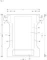
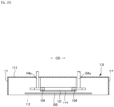
- Figs. 1 to 6 illustrate examples of a tape-type disposable diaper, in which the reference sign X indicates the maximum width of the diaper excluding the fastening tapes, and the reference sign L indicates the maximum length of the diaper.
- Each component member is fixed or bonded in the same manner as known diapers as necessary except for the fixing or bonded portion described below.
- a hot melt adhesive or welding heat welding, ultrasonic welding
- This tape type disposable diaper has a basic structure in which an absorber 50 is interposed between a liquid pervious top sheet and a liquid impervious sheet located on the external surface side.
- the tape type disposable diaper includes a ventral side end flap portion EF, a dorsal side end flap portion EF, and a pair of side flap portions SF.
- the ventral side end flap portion EF and the dorsal side end flap portion EF are portions extending to the front side and the back side of the absorber 50 respectively and not including the absorber 50.
- the pair of the side flap portions SF extends laterally from the side edges of the absorber 50.
- a fastening tape 13 is provided in each of the side flap portions SF in a dorsal side portion B.
- the fastening tape 13 is engaged at an appropriate place on the external surface of the ventral side portion F in a state in which the side flap portion SF of the dorsal side portion B is overlaid on the external side of the side flap portion SF of the ventral side portion F.
- the entire external surface of the absorbent main unit 10 and the respective side flap portions SF is formed by an outer sheet 12.
- a liquid impervious sheet 11 is fixed to the internal surface side of the outer sheet 12 with an adhesive such as a hot melt adhesive.
- the absorber 50, an intermediate sheet 40, and a top sheet 30 are stacked in this order on the internal surface side of the liquid impervious sheet 11.
- the top sheet 30 and the liquid impervious sheet 11 are rectangular in shape and have somewhat larger sizes in the front-back direction LD and the width direction WD than the absorber 50.
- peripheral edge portions protruding from the side edges of the absorber 50 in the top sheet 30 and the peripheral edge portions protruding from the side edges of the absorber 50 in the liquid impervious sheet 11 are bonded by a hot melt adhesive or the like. Further, the liquid impervious sheet 11 is formed to be slightly wider than the top sheet 30.
- three-dimensional side gathers 60 and 60 projecting (standing) to the skin side of a wearer are provided, and gather sheets 62 and 62 forming the three-dimensional side gathers 60 and 60 are fixed in ranges on the both sides of the top sheet 30 to the inner surfaces of the side flap portions SF.
- the outer sheet 12 is a sheet constituting the external surface of a product.
- the outer sheet 12 has a shape in which the intermediate portions in the front-back direction LD on the both side portions are narrowed, and these portions surround the wearer's legs.
- a nonwoven fabric is suitable for the outer sheet 12, but it is not limited thereto.
- the type of the nonwoven fabric is not particularly limited.
- As a raw material fiber for example, in addition to synthetic fibers such as olefin type such as polyethylene or polypropylene, polyester type, and polyamide type, regenerated fibers such as rayon and cupra, and natural fibers such as cotton can be used.
- a spun lace method As a processing method, a spun lace method, a spun bond method, a thermal bond method, an air through method, a needle punch method, and the like can be used.
- a long-fiber nonwoven fabric such as a spunbonded nonwoven fabric, an SMS nonwoven fabric, and an SMMS nonwoven fabric are preferable in that both good texture and strength can be compatible.
- the nonwoven fabrics are adhered to each other with a hot melt adhesive or the like.
- the basis weight of the fiber is desirably 10 to 50 g/m 2 , particularly desirably 15 to 30 g/m 2 .
- the outer sheet 12 can be omitted, and in that case, the liquid impervious sheet 11 can have the same shape as that of the outer sheet 12, such that the outer surface of a product can be formed.
- the material of the liquid impervious sheet 11 is not particularly limited, for example, an olefin resin such as polyethylene or polypropylene, a laminated nonwoven fabric obtained by stacking a nonwoven fabric on a polyethylene sheet or the like, a nonwoven fabric in which liquid permeability is substantially secured through a water proof film (in this case, a liquid impervious sheet is formed by the waterproof film and the nonwoven fabric) can be exemplified.
- an olefin resin such as polyethylene or polypropylene
- a laminated nonwoven fabric obtained by stacking a nonwoven fabric on a polyethylene sheet or the like a nonwoven fabric in which liquid permeability is substantially secured through a water proof film (in this case, a liquid impervious sheet is formed by the waterproof film and the nonwoven fabric)
- a liquid impervious sheet is formed by the waterproof film and the nonwoven fabric
- a microporous sheet As a sheet of this liquid-impervious and moisture-permeable material, for example, a microporous sheet can be exemplified which is obtained by kneading an olefin resin such as polyethylene resin or polypropylene resin and an inorganic filler, forming a sheet with the kneaded materials and monoaxially or biaxially stretching the sheet.
- nonwoven fabrics using micro denier fibers and a sheet that is liquid impervious without using a water proof film can also be used as the liquid impervious sheet 11.
- the sheet has liquid impermeability by having high leak proof by reducing air gaps of fibers by heating or applying pressure and by applying a superabsorbent resin, a hydrophobic resin, or a water repellent agent.
- a porous or non-porous nonwoven fabric having liquid permeability can be used as the top sheet 30, a porous or non-porous nonwoven fabric having liquid permeability.
- the type of constituent fibers of the nonwoven fabric is not particularly limited.
- the nonwoven fabric can include synthetic fibers such as olefin type such as polyethylene and polypropylene, polyester type, and polyamide type, regenerated fibers such as rayon and cupra, natural fibers such as cotton, mixed fibers and conjugate fibers in which two or more of these are used, and the like.
- the nonwoven fabric may be manufactured by any processing. Examples of processing methods can include known methods such as a spun lace method, a spun bond method, a thermal bond method, a melt blown method, a needle punch method, an air through method, and a point bond method.
- the spun lace method is preferable when flexibility and drapeability are required
- the thermal bonding method is preferable when bulkiness and softness are required.
- the intermediate sheet 40 is bonded to the back surface of the top sheet 30 to promptly move excretion liquid passing through the top sheet 30 to the side of the absorber 50 and to prevent returning.
- heat embossing or ultrasonic welding can be used in addition to using a hot melt adhesive.
- a resin film having a large number of through holes can be used in addition to using a nonwoven fabric.
- a nonwoven fabric a material similar to that described in the section of the top sheet 30 can be used. However, the material having a higher hydrophilicity than that of the top sheet 30 or the material having a high fiber density is preferable since those have excellent liquid transfer characteristics from the top sheet 30 to the intermediate sheet 40.
- the intermediate sheet 40 in the illustrated embodiment is shorter than the width of the absorber 50 and disposed at the center portion, it may be provided throughout the maximum width.
- the length of the intermediate sheet 40 in the front-back direction LD may be the same as the maximum length of the diaper, may be the same as the length of the absorber 50, or may be within a short length range around a region receiving a liquid.
- the three-dimensional side gathers 60 projecting (standing) from the inner faces on the both sides of the product in the width direction WD.
- Each three-dimensional side gather 60 is composed of gather sheet 62 and one or a plurality of elongated elastically stretchable members 63 fixed to the gather sheet 62 in a stretched state along the front-back direction LD.
- this gather sheet 62 a water repellent nonwoven fabric can be used, and rubber thread and the like can be used as the elastically stretchable member 63.
- a plurality of the elastically stretchable members may be provided on each side, or only one elastically stretchable member may be provided on each side.
- the inner surface of the gather sheet 62 has a fixed start point in the width direction WD on the side portion of the top sheet 30. A portion outside in the width direction WD from this fixed start point is fixed with a hot melt adhesive or the like on the side portion of the liquid impervious sheet 11 and the side portion of the outer sheet 12 positioned at the outside portion.
- the inside in the width direction WD from the fixed start point of each three-dimensional side gather 60 is fixed on the top sheet 30 at both ends of the product in the front-back direction LD.
- the portion therebetween is a non-fixed free portion erected by contraction force of one or a plurality of the elastically stretchable members 63. Since the diaper is attached to the body in a boat shape in the wearing of the diaper, and the contraction force of one or a plurality of the elastically stretchable members 63 acts, the three-dimensional side gathers 60 erect by the contraction force of one or a plurality of the elastically stretchable members 63 and come in close contact with the legs. As a result, so-called lateral leakage from around the legs is prevented.
- both end portions in the front-back direction LD in the portion of the inside in the width direction WD of each gather sheet 62 are fixed in a state folded in two having a base end side portion, which extends inward from a portion outside in the width direction WD and a tip side portion, which is folded back on the body side from the end edge on the center side in the width direction WD of the base end side portion and extending outward in the width direction WD, and the portion therebetween may be a non-fixed free portion.
- each side flap portion SF on the outside in the width direction WD in the vicinity of the fixed start point of the fixed portion of the gather sheet 62, between the gather sheet 62 and the liquid impervious sheet 11, the elastically stretchable members 64, which are made of rubber threads and the like, around the leg portions are fixed in a state stretching along the front-back direction LD, whereby the leg portion of each side flap portion SF is formed as a flat gather.
- the elastically stretchable members 64 around each leg portion can also be disposed between the liquid impervious sheet 11 and the outer sheet 12 in the side flap portion SF.
- a plurality of elastically stretchable members 64 around the leg portions may be provided on each side, or only one elastically stretchable member 64 may be provided on each side.
- each fastening tape 13 includes a sheet base material forming a tape attaching portion 13C fixed to the side portion of a diaper and a tape main unit section 13B projecting from the tape attaching portion 13C, and an engagement portion 13A with respect to the ventral side, which is provided in the middle portion in the width direction WD of the tape main unit section 13B in the seat base material.
- a tip end side from the engagement portion 13A is a tab part.
- the tape attaching portion 13C of the fastening tape 13 is sandwiched between the gather sheet 62 forming the inner layer in the side flap portion and the outer sheet 12 forming the outer layer and is adhered to the both sheets 62 and 12 with the hot melt adhesive.
- the engagement portion 13A is bonded to the sheet base material with an adhesive so that it cannot be removed.
- a hook member (male member) of a mechanical fastener (hook and loop fastener) is suitable as the engagement portion 13A.
- the hook member has a large number of engagement projections on its outer surface side.
- the engagement projection has a check mark shape, a J shape, a mushroom shape, a T shape, and a double J shape (a shape bonded back to back of a J shape), but may have any shape.
- an adhesive material layer can also be provided as an engagement portion of the fastening tape 13.
- nonwoven fabrics such as a spunbonded nonwoven fabric, an air-through nonwoven fabric, and a spunlace nonwoven fabric
- a plastic film, a polyethylene laminated nonwoven fabric, paper, or a composite material thereof can be used as the sheet base material forming from the tape attaching portion to the tape main unit section.
- the target sheet 12T having a target for facilitating engagement at the engagement portion of each fastening tape 13 in the ventral side portion F.
- the target sheet 12T can be used having a large number of loops made of threads to which engagement projections of the hook member are tangled, are provided on a surface of the sheet base member made of a plastic film or a nonwoven fabric.
- an adhesive layer it is possible to use a sheet base material made of a plastic film having a smooth surface with high adhesiveness and subjected to a release treatment.
- the target sheet 12T may be omitted, and the hook member 13A can be entangled and engaged with the nonwoven fabric of the outer sheet 12.
- the target sheet 12T may be provided between the outer sheet 12 and the liquid impervious sheet 11.
- the absorber 50 is a part that absorbs and retains the liquid content of excrement.
- the absorber 50 can be adhered to the components on at least one of the front surface side and back surfaces side via an adhesive such as a hot melt adhesive.
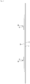
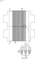
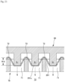
- the absorber 50 is a cell absorber 50 having the front surface side sheet 51; the back surface side sheet 52 disposed on the back surface side of the front surface side sheet 51; the cells (small chambers) 55 each of which is surrounded by the bonded portions 54 of the front surface side sheet 51 and the back surface side sheet 52, and in each of which the front surface side sheet 51 and the back surface side sheet 52 are not bonded; and the super absorbent polymer particles 53 contained in each of the cells 55.
- the cell absorber 50 can be wrapped with a wrapping sheet (not shown).
- one wrapping sheet can be wrapped in a cylindrical shape so as to surround the absorber on the front and back surfaces and the both side surfaces of the absorber 50 and two wrapping sheets can be also wrapped so as to sandwich the absorber from both the front surface side and the back surface side.
- tissue paper, particularly crepe paper, a nonwoven fabric, a polyethylene laminated nonwoven fabric, a sheet with small holes, and the like can be used as the wrapping sheet.
- the wrapping sheet be a sheet through which the superabsorbent polymer particles do not pass.
- a nonwoven fabric is used for the wrapping sheet, a hydrophilic SMS nonwoven fabric (SMS, SSMMS, etc.) is particularly suitable, and polypropylene and polyethylene/polypropylene composite material can be used as a material.
- the basis weight is preferably 5 to 40 g/m 2 , particularly preferably 10 to 30 g/m 2 .
- the front surface side sheet 51 may be a liquid-pervious material or a liquid impervious material, but preferably it is a liquid-pervious material when it is positioned on the top sheet 30 side as indicated in the illustrated embodiment.
- a porous or non-porous nonwoven fabric or a porous plastic sheet can be used for the front surface side sheet 51.
- examples of the constituent fibers include synthetic fibers (including not only single component fibers but also conjugate fibers) such as olefin type such as polyethylene or polypropylene, polyester type, and polyamide type, regenerated fibers such as rayon and cupra, and natural fibers such as cotton, but it can be selected without limitation, and it is preferable to use a thermoplastic resin fiber because of excellent thermal processability.
- the fiber bonding method of the nonwoven fabric is not particularly limited, but to prevent the superabsorbent polymer particles 53 from falling off through the sheet, it is preferable to use a bonding method which increases fiber density, such as a spun bond method, a melt blown method, and a needle punch method.
- its pore diameter is preferably smaller than the outer shape of the superabsorbent polymer particle 53 to prevent the superabsorbent polymer particle 53 from falling off through the sheet.
- a hydrophilic agent can also be contained.
- a recess 51c recessed from the back surface side to the front surface side is preferably formed.
- the back surface side sheet 52 may be made of the same material as the front surface side sheet 51, but in the case where the front surface side sheet 51 is composed of a liquid pervious material, a liquid impervious material can be used for the back surface side sheet 52.
- the liquid impervious material usable for the back surface side sheet 52 can be appropriately selected and used from the materials described in the section of the liquid impervious sheet 11.
- the front surface side sheet 51 and the back surface side sheet 52 may be one side layer and another side layer in which one sheet of material is folded in two.
- the superabsorbent polymer particles 53 may not be fixed to the front surface side sheet 51 and the back surface side sheet 52 and may be freely movable, but may also be bonded or adhered to the front surface side sheet 51 and the back surface side sheet 52. Also, the superabsorbent polymer particles 53 may be agglomerated to some extent.
- the particle diameter of the superabsorbent polymer particles is not particularly limited, but for example, when the particles are sieved (shaking for five minutes) using a standard sieve (JIS 28801-1:2006) of 500 ⁇ m and the particles subjected to sieving with the 500 ⁇ m standard sieve are further sieved (shaking for five minutes) using the standard sieve (JIS Z8801-1: 2006) of 180 ⁇ m, preferably the proportion of the particles remaining on the 500 ⁇ m standard sieve is 30% by weight or less, and the proportion of the particles remaining on the 180 ⁇ m standard sieve is 60% by weight or more.
- a standard sieve JIS 28801-1:2006
- the material of the superabsorbent polymer particles 53 can be used without particular limitation, but the material having the water absorption capacity of 40 g/g or more is suitable.
- the superabsorbent polymer particles 53 include starch-based, cellulose-based, and synthetic polymer-based, and starch-acrylic acid (salt) graft copolymers, saponified starch-acrylonitrile copolymers, sodium carboxymethyl cellulose crosslinked products, acrylic acid (salt) polymers and the like.
- the shape of the superabsorbent polymer particles 53 the shape of particulate materials which are usually used is suitable, but other shapes can also be used.
- the superabsorbent polymer particles 53 having a water absorption rate of 70 seconds or less, particularly 40 seconds or less, are suitably used. If the water absorption rate is too slow, so-called returning, in which the liquid fed into the absorber 50 returns to the outside of the absorber 50, is likely to occur.
- the superabsorbent polymer particles 53 having the gel strength of 1,000 Pa or more are preferably used. Thereby, even when the absorber 50 is bulky, it is possible to effectively suppress stickiness after liquid absorption.
- the basis weight of the superabsorbent polymer particles 53 can be appropriately determined according to the absorption amount required for the use of the absorber 50. Therefore, although it cannot be said unconditionally, the basis weight can be 50 to 350 g/m 2 . When the basis weight of the polymer is less than 50 g/m 2 , it is difficult to secure the absorption amount. When it exceeds 350 g/m 2 , the effect is saturated.
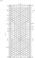
- the planar shape of the cell 55 can be determined as appropriate, and it may be circular, elliptical, or the like, but the shape is preferably a polygon to provide a denser arrangement.
- the cells 55 may be arranged by combining multiple types of cells varying at least one of the shape and size.
- planar arrangement of the cells 55 (that is, also the collecting portions of the superabsorbent polymer particles 53) can be appropriately determined, a regularly repeated plane arrangement is preferred.
- a regularly repeated plane arrangement such as an oblique lattice shape as illustrated in Fig. 8(a) , a hexagonal lattice shape (also referred to as a staggered shape) as illustrated in Fig. 8(b) , a square lattice shape as illustrated in Fig. 8(c) , a rectangular lattice shape as illustrated in Fig. 8(d) , and a parallel lattice shape as illustrated in Fig.
- a group of the cells 55 (the group may be regularly or irregularly arranged, and may be a pattern or a letter shape) can be regularly repeated.
- each cell 55 can be appropriately determined, and for example, the length 55L in the front-back direction LD can be about 8 to 30 mm, and the length 55W in the width direction WD can be about 10 to 50 mm.
- the bonded portion 54 for bonding the front surface side sheet 51 and the back surface side sheet 52 be bonded by welding the front surface side sheet 51 and the back surface side sheet 52 like ultrasonic welding or heat sealing, but it may be bonded with a hot melt adhesive.
- the bonded portions 54 may be arranged in a dotted line shape (intermittently in a direction surrounding each cell 55) as indicated in the illustrated embodiment and the bonded portion also may be formed in a continuous linear shape.
- the superabsorbent polymer particles 53 are not present between the bonded portions 54 in the direction surrounding the cell 55, or even if the superabsorbent polymer particles 53 are present, less superabsorbent polymer particles than those in the cell 55 are included.
- the size of the bonded portion 54 for bonding the front surface side sheet 51 and the back surface side sheet 52 can be appropriately determined, and for example, the line width (dimension in the direction orthogonal to the direction surrounding the cell 55) 54W can be about 0.6 to 8.0 mm.
- the length 54L of the bonded portion 54 in the direction surrounding the cell 55 is about 0.6 to 8.0 mm, and the point interval 54D is about 0.8 to 10.0 mm.
- the line width 54W is about 1.0 to 4.0 mm
- the length 54L of the bonded portion 54 is about 1.5 to 4.0 mm
- the point interval 54D is about 0.8 to 2.5 mm.
- the line width 54W is about 0.6 to 3.5 mm
- the length 54L of the bonded portion 54 is about 0.6 to 2.5 mm
- the point interval 54D is about 1.0 to 4.0 mm.
- the width of the bonded portion 54 in the case where the bonded portion 54 is formed in a continuous linear shape, and the line width 54W in the case where the bonded portions 54 are formed in a dotted line shape are constant in the direction surrounding the cell 55 and also can be changed.
- the shape of each bonded portion 54 can be appropriately determined, and all of the bonded portions have the same shape, or the bonded portions may have different shapes depending on their positions.
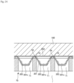
- each cell 55 has a polygonal shape, it is preferable to provide each bonded portion 54 at the intermediate position of each side of the polygon.
- each strong bonded portion 54a at a position of each vertex, but it is preferable not to provide the weak bonded portion 54b at the position of each vertex so that the weak bonded portion 54b can be peeled off easily, resulting in smooth coalescing of the cells 55.
- the bonded portion 54 is provided at the position of each vertex, it is desirable that the bonded portion 54 has a radial (star) shape protruding in the direction of each side.
- the bonded portions 54 surrounding the cell 55 are partly or totally peeled off, and the cell 55 coalesces with the adjacent cells 55 to form a larger cell 55.
- Such a function is realized, for example, by providing the weak bonded portions 54b with weakened bonding strength in appropriate places and by determining the type and amount of the superabsorbent polymer particles 53 disposed in each cell 55 such that the volume of the superabsorbent polymer particles 53 in the cell 55 upon the saturation absorption becomes sufficiently larger than the volume of the cell 55.
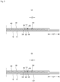
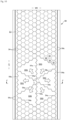
- the bonding strength of the bonded portions 54 may be uniform over the entire absorber 50, as illustrated in Figs. 7 , 9 , and 10 , one of the preferable embodiments is that the planar region of the absorber 50 is divided into a plurality of compartments 55G, the bonded portions 54 surrounding the group of the cells 55 of each compartment 55G are formed as strong bonded portions 54a having relatively high bonding strength, the bonded portions 54 located inside the compartment 55G are formed as weak bonded portions 54b having relatively low bonding strength, and the weak bonded portions 54b are peeled off in preference to the strong bonded portions 54a.
- Such a function is realized, for example, by determining the type and amount of the superabsorbent polymer particles 53 disposed in each cell 55 such that the volume of the superabsorbent polymer particles 53 in the cell 55 upon saturation absorption becomes sufficiently larger than the volume of each cell 55, and the volume of the superabsorbent polymer particles 53 in the compartment 55G upon saturation absorption becomes less than the volume of the cells 55 of the entire compartment 55G surrounded by the strong bonded portions 54a upon the coalescence.
- the arrangement of the strong bonded portions 54a is not particularly limited, for example, as indicated in the illustrated embodiment, if the strong bonded portions 54a continue throughout a certain range in a specific direction, such as the front-back direction LD, the width direction WD, and the oblique direction, the cells 55 on the both sides are swollen due to the absorption by the internal superabsorbent polymer particles 53, the strong bonded portions 54a are however not peeled off to the end. Therefore, after the absorption, the grooves with the bottom portions of the strong bonded portions 54a are formed along the specific directions, and the liquid diffusibility in the directions along the grooves is improved.
- the strong bonded portions 54a continue in the width direction WD or in the oblique direction, it is possible to prevent the uneven distribution which would be caused by the movement of the gelled superabsorbent polymer particles 53 swollen due to the absorption as well as to improve the liquid diffusibility in the directions. Further, if the bonded portions positioned on the outermost side in the width direction WD are peeled off, there is a possibility that the superabsorbent polymer particles 53 or the gelled superabsorbent polymer particles 53 leak out laterally from the absorber 50, and it is therefore desirable that such bonded portions are the strong bonded portions 54a.
- the front surface side sheet 51 and the back surface side sheet 52 are extended laterally in the width direction WD to some extent beyond the region where the cells 55 are formed, and the edge bonded portions 54c are provided in the extended portions for the reinforcement.
- the difference in bonding strength may be easily made by changing the area of each bonded portion 54 but is not limited thereto.
- a method in which the type of a hot melt adhesive is varied depending on the sites can be used.
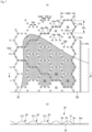
- an area 53A having a pattern of hatched lines indicates a region for containing the superabsorbent polymer particles 53. Since this region is based on assumption of the shape of a region in which the superabsorbent polymer particles 53 are dispersed in the manufacturing, there are portions which are not covered by the pattern of the hatched lines in the cells 55 in the peripheral edge.
- the positions of the superabsorbent polymer particles 53 in the cell 55 are not fixed in a state of the product, and the superabsorbent polymer particles 53 can be distributed throughout the cells 55 in the same manner as in the state illustrated in Fig. 7 .
- the amount of the superabsorbent polymer particles 53 contained in the empty cell 56 is preferably 1/2 or less, particularly 1/10 or less, of the other cells in terms of weight ratio, and it is particularly preferable that the superabsorbent polymer particles 53 are not contained at all in the empty cell.
- the front end and the back end of the absorber 50 are formed by cutting into the individual absorbers 50 in the manufacturing, if the superabsorbent polymer particles 53 are contained in portions where the cutting is performed, the life of a blade of a cutting device may be shortened. Therefore, it is desirable that at least the cells 55 located at the positions through which the front and back ends of the absorber 50 pass be the empty cells 56. Further, in the absorber 50 obtained by mixing superabsorbent polymer particles 53 with a hydrophilic short fiber such as fluff pulp, and being accumulated in a cotton form, generally, the intermediate portion in the front-back direction LD is formed in a narrow shape so as to be along the legs.
- the absorber 50 by setting, the cells 55 on the both sides in the intermediate portion in the front-back direction LD, as the empty cells 56, the intermediate portion in the front-back direction LD will be less swollen even after the absorption. Therefore, the absorber 50 has a shape that fits around the legs even after the absorption.
- the superabsorbent polymer particles 53 are uniformly dispersed throughout the entire region for containing the superabsorbent polymer particles 53 (the region excluding the portions to be the empty cells 56) on the front surface side sheet 51 or the back surface side sheet 52, and then the bonded portions 54 are formed to bond the front surface side sheet 51 and the back surface side sheet 52 as one unit and to confine the superabsorbent polymer particles 53 in each cell 55.
- the amount of the superabsorbent polymer particles 53 contained in the peripheral cells 55 is less than the amount of the same contained in the cells 55 positioned inside the peripheral cells 55, and in the case where the cells 55 are further provided outside the peripheral cells 55, these outer cells 55 become the empty cells 56 which do not substantially contain the superabsorbent polymer particles 53.
- the superabsorbent polymer particles 53 are contained in the cells 55, but it is also possible to contain the superabsorbent polymer particles 53 together with particulate materials other than the superabsorbent polymer particles 53, such as deodorant particles.
- the above-described cell absorber 50 is manufactured by conveying a continuous belt-shaped first sheet along a continuous direction, sequentially forming a large number of recesses on the first sheet in this conveying process at intervals in the CD while the first sheet is conveyed, feeding particulate materials including superabsorbent polymer particles to the recesses of the first sheet on the downstream side of the recess forming position, overlapping a belt-shaped second sheet continuous in the MD on the first sheet on the downstream side of the feeding position of the particulate materials, bonding portions among the recesses of the first sheet and the second sheet on the downstream side of the position where the second sheet is overlapped, sequentially forming a continuous series of the absorbers in which a large number of cells containing particulate materials are arranged, and cutting a continuous series of the absorbers into individual absorbers at intervals in the MD.
- the first sheet is the front surface side sheet of the above-described cell absorber 50 and the second sheet is the back surface side sheet, those may be set opposite
- Fig. 12 illustrates a specific example of a device for manufacturing the cell absorber.
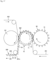
- This manufacturing device is based on an anvil roll 70 which is driven to rotate about a lateral rotating shaft.
- the first sheet feeding unit 80, a recess forming unit 90, a particulate material feeding device 100, and a second sheet feeding unit 150 are provided.
- a welding unit 160 is provided on the downstream side in the rotation direction of the feeding unit of the second sheet.
- the anvil roll 70 has a large number of concaves 71 arranged at intervals on the outer peripheral surface, and for each concave 71, projections 72 provided so as to surround the concave 71 in a portion among the concaves 71.
- the concave 71 on the outer peripheral surface of the anvil roll 70 communicates with the inner space partitioned into a suction compartment 73 and a non-suction compartment 74 in the rotation direction.
- a suction device such as a suction fan (not illustrated) is connected to the suction compartment 73 in the inner space of the anvil roll 70, and the inside of the concave 71 can be sucked.
- neither a suction port nor a discharge port is formed in the portion among the concaves 71 on the outer peripheral surface of the anvil roll 70.
- the first sheet feeding unit 80 feeds a continuous belt-shaped first sheet 201 made of a liquid pervious nonwoven fabric in the rotation direction of the anvil roll 70 along the outer peripheral surface of the anvil roll 70.
- the first sheet feeding unit 80 includes various devices such as a guide roll and a drive roll in a path from the material roll of the first sheet 201 (not illustrated) to the outer peripheral surface of the anvil roll 70.
- the first sheet feeding unit 80 includes a wave-forming device 81.
- the wave-forming device 81 includes a groove roll 82 having a large number of grooves 82g continuous in the roll circumferential direction and arranged in the roll length direction on the outer peripheral surface of the groove roll, and a convex roll 83 having a large number of convex portions 83p continuous in the roll circumferential direction and arranged in the roll length direction on the outer peripheral surface of the convex roll, while the groove roll 82 and the convex roll 83 are opposed to each other such that the grooves 82g and the continuous convex portions 83p are engaged with each other.
- the wave-forming device includes a heating unit 84, where the groove roll 82 and the convex roll 83 pass, for heating the first sheet 201 to a melting temperature or lower.
- the heating unit 84 is a heating box 84 which surrounds the convex roll 83 and the groove roll 82 and keeps the internal atmosphere at a predetermined temperature, but a heating unit for heating at least one of the groove roll 82 and the convex roll 83 may be used, or one heating unit for heating one of these rolls and the other heating unit for the other of these rolls may be combined.
- the temperature of the first sheet 201 in the wave-forming device 81 can be appropriately determined according to the type of the material, but it is preferable to set it at 40 to 100°C assuming the case of using a normal thermoplastic nonwoven fabric.
- the first sheet 201 may be recessed to reach at least the second sheet 202 feeding unit by taking air in the concave 71 by the above-described suction unit.
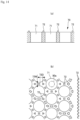
- a push-in roll 90 is provided as the recess forming unit 90.
- the push-in roll 90 opposed to the anvil roll 70 has push-in pins 91 which enter the respective concaves 71 of the anvil roll 70.
- the push-in roll 90 forms receiving recesses 201c on the first sheet 201 by feeding the continuous belt-shaped first sheet 201 in the rotation direction of the anvil roll 70 between the anvil roll 70 and the push-in roll 90 and pushing the first sheet 201 into the concaves 71 by the push-in pins 91.
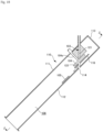
- the particulate material feeding device 100 includes the particulate material storage tank 101 for storing the particulate materials 203, the delivery device 102 for continuously delivering the particulate materials 203 stored in the particulate material storage tank 101, a chute 103 for dropping and transferring the particulate materials 203 delivered from the delivery device 102 and dropping and feeding the particulate materials 203 to a feeding position, blocking bodies 104 and 105 which intermittently enter blocking positions for blocking at least a part of particulate passage in a cross-sectional direction in the chute 103, from a non-blocking position, and a recovery path 106 branched from the chute 103 so as to discharge the particulate materials 203 blocked by the blocking bodies 104 and 105 to the outside of the chute 103.
- a so-called rotary feeder 102 is connected to the lower end outlet of the particulate material storage tank 101, and by this rotary feeder 102, the particulate materials 203 stored in the particulate material storage tank 101 are continuously discharged and continuously and quantitatively fed to the chute 103.
- the delivery device 102 is not limited to the rotary feeder 102, and other known particulate material feeding devices 100 can be used. Further, the particulate materials may not be quantitatively supplied, for example, the feeding amount may be continuously or gradually changed.
- the chute 103 may extend straight in the substantially vertical direction as indicated in the illustrated embodiment, and it may have a curved portion or a bent portion that draws an arc in part or in whole, unlike the illustrated embodiment.
- the passage position in the cross-sectional direction in the chute 103 may be changed continuously or gradually in the transfer direction, but in the case where intermittent feeding is performed only in a part in the CD, the passage position is desirably not changed in the CD or at least not reduced.
- the blocking position of the blocking body 104, 105 is not particularly limited as long as it is a position blocking at least a part of the particulate passage in the sectional direction, but for example, the blocking position may be a position where the particulate passage in the middle in the CD in the chute 103 is not blocked, the particulate passage on the both sides is blocked, or a position where the particulate passage throughout the entire cross-sectional direction in the chute 103 is blocked.
- the first blocking body 104 may be provided at one of these blocking positions, and the second blocking body 105 may be provided on the other one.
- the blocking bodies 104 and 105 can be linearly reciprocated with respect to the blocking positions by a crank mechanism or a fluid pressure cylinder, the blocking bodies 104 and 105 can be rotated about one point by a rotary drive source such as a motor to pass the rotational movement locus of the blocking bodies 104 and 105 through the blocking position, or the blocking bodies 104 and 105 can be rotated in parallel by the crank mechanism to pass the rotational movement locus of the blocking bodies 104 and 105 through the blocking position.
- a rotary drive source such as a motor to pass the rotational movement locus of the blocking bodies 104 and 105 through the blocking position
- the blocking bodies 104 and 105 can be rotated in parallel by the crank mechanism to pass the rotational movement locus of the blocking bodies 104 and 105 through the blocking position.
- the recovery path 106 is a passage having an inlet in a direction in which the particulate materials 203 collide with the blocking bodies 104 and 105 and move, and the particulate materials 203 blocked by the blocking bodies 104 and 105 are discharged to the outside of the chute 103 by the moving force of a suction fan or the like or under their own weights. It is desirable that the blocked particulate materials 203 collected via the recovery path 106 be returned to the particulate material storage tank 101 for reuse as indicated in the illustrated embodiment, but the blocked particulate materials 203 may be temporarily stored in a storage tank or a storing bag for reuse, or may not be reused.
- the particulate material feeding device 100 in the illustrated embodiment will be described in further detail.
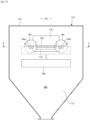
- the chute 103, the blocking bodies 104 and 105, and the recovery path 106 are included in one box type unit.
- This box-type unit has a top plate 111, a bottom plate 112, and a side plate 113 covering the periphery of a space between the top plate 111 and the bottom plate 112.
- the box-type unit has a casing 110 arranged to be inclined with respect to the horizontal direction, a chute feeding port 114 provided on the upper side in the inclination direction of the top plate, a chute discharge port 115 provided on the lower side in the inclination direction of the chute feeding port 114, and chute main unit sections 121 and 122 for connecting these ports in the casing 110.
- a portion of the casing 110 on the lower side in the inclination direction of the chute main unit section 122 is a start point portion of the recovery path 106.
- the chute feeding port 114, the chute main unit sections 121 and 122, and the chute discharge port 115 have a substantially rectangular cross-sectional surface whose long side extends along the CD.
- the chute main unit sections 121 and 122 have a first passage 121 having an inlet provided below the chute feeding port 114 and extending in the substantially vertical direction from the inlet to a position above the first blocking position, and a second passage 122 having an inlet below the first blocking position and extending in the substantially vertical direction from the inlet to a position above the second blocking position on the chute discharge port 115.
- the first passage 121 is a passage having a substantially rectangular cross-sectional surface formed with a pair of planes extending in the MD and a pair of planes extending in the CD.
- the second passage 122 is a through section having a substantially rectangular cross-sectional surface formed below the first blocking position in the partition plate 116 extending from the upper side to the lower side of the first blocking position in the inclination direction.
- the space of the first blocking position located between the outlet of the first passage 121 and the upper face of the partition plate 116 and the space of the second blocking position located between the outlet of the second passage 122 and the chute discharge port 115 open in the recovery path 106 on the obliquely lower side.
- the first blocking body 104 in the illustrated embodiment comprises blade bodies (such as impellers) provided on the both sides in the CD in the first blocking position.
- Each black body is provided in a part of the rotation direction of a rotary shaft 104s extending in a direction intersecting the inclination direction on both sides in the CD of the first blocking position.
- the first blocking body 104 repeats entering from the obliquely upper side and retracting from the obliquely lower side with respect to the both sides in the CD at the first blocking position.
- all of the particulate materials 203 dropping toward the inlet of the second passage 122 are allowed to pass through.
- the blocking body 104 does not block the particulate passage in the middle in the CD and blocks the particulate passage on the both sides thereof, as illustrated in Figs 25 and 26 . Therefore, the space at the first blocking position also opens to the side such that the first blocking body 104 can enter and retract.
- the particulate materials 203 blocked by the first blocking body 104 move on the first blocking body 104 and the partition plate 116 and are introduced into the recovery path 106 on the lower side in the inclination direction.
- the second blocking body 105 in the illustrated embodiment is a blocking plate that is dimensioned to cover the entire chute discharge port 115 and that extends along the inclination direction.
- the second blocking body 105 is supported to be reciprocable in the inclination direction, and passes through the chute discharge port 115 in the process.
- the second blocking body 105 is in the retracted position not covering the chute discharge port 115, all of the particulate materials 203 dropping toward the chute discharge port 115 are passed.
- the second blocking body 105 passes through the blocking position on the chute discharge port 115, as indicated by two-dot chain lines in Figs. 13 and 19 and illustrated in Fig. 27 , all the particulate materials 203 dropping toward the chute discharge port 115 are blocked.
- the particulate materials 203 blocked by the second blocking body 105 move on the second blocking body 105 and the bottom plate 112 and are introduced into the recovery path 106 on the lower side in the inclination direction.
- the particulate materials 203 discharged from the chute discharge port 115 are sequentially dropped and fed onto the first sheet 201 wound around the outer peripheral surface of the anvil roll 70.
- the second sheet feeding unit 150 disposed on the downstream side in the rotation direction of the particulate material feeding device 100 feeds a continuous belt-shaped second sheet 202 made of a liquid pervious nonwoven fabric in the rotation direction of the anvil roll 70 along the outer peripheral surface of the anvil roll 70.
- the second sheet feeding unit 150 includes various devices such as a guide roll and a drive roll in a path from the material roll (not illustrated) of the second sheet 202 to the outer peripheral surface of the anvil roll 70.
- the guide plate 151 which approaches the vicinity of the outer peripheral surface of the anvil roll 70 in the tangential direction, is disposed, and the second sheet 202 passes over the guide plate 151, is folded back at its tip, and is fed in the rotation direction along the outer peripheral surface of the anvil roll 70. Therefore, the tip end of the guide plate 151 is an arcuate surface of a curved surface extending along the guiding direction of the second sheet 202.
- the welding unit 160 is not particularly limited as long as it welds the first sheet 201 and the second sheet 202.
- a heating roll 161 may be used as indicated in the embodiment of Fig. 17 .
- the first sheet 201 is supplied to the anvil roll 70 by the first sheet feeding unit 80, and the receiving recesses 201c are sequentially formed in the first sheet 201 by the recess forming unit 90.
- the receiving recesses 201c are formed more firmly as compared with the case where the receiving recesses 201c are formed by suction, and therefore it is preferable since the particulate materials 203 easily drop into each receiving recess 201c when the particulate materials are fed.
- the first sheet 201 Prior to the feeding of the first sheet 201 to the anvil roll 70, if the first sheet 201 is pretreated by the wave-forming device 81 as indicated in the illustrated embodiment, it is softened and becomes stretchable by the change in the fiber structure due to stretching of the first sheet 201. Therefore, in addition to further firmly forming the receiving recesses 201c in forming the receiving recesses 201c, the first sheet 201 is firmly sucked into the concaves 71 by suction such that the first sheet 201 becomes to have a surface shape easier to drop in the receiving recesses 201c, and thus it is preferable.
- the receiving recess 201c are formed by the push-in roll and to what extent the wave-forming is performed can be determined as appropriate, but in the usual case, it is desirable that the pushing depth 91d of the first sheet 201 by the push-in pin 91 be 2 to 10 mm, the wave height 81h in wave-forming by the wave-forming device 81 be 1 to 8 mm, and the peak-to-peak interval 81d of the adjacent waves in the CD be 1 to 5 mm.
- the first sheet 201 on which the receiving recesses 201c is formed is rotated to the feeding position of the next particulate material feeding device 100 while being wound around the anvil roll 70.
- the concaves 71 are located in the suction compartment 55G from the stage of forming the receiving recesses 201c, and the concaves 71 are continuously sucked, the receiving recesses 201c are firmly held in the concaves 71 while the receiving recesses remain their formed shapes.
- the sucking is continued at least to the second sheet 202 feeding position, preferably to the welding position. As illustrated in Figs.
- the particulate materials 203 are dropped and fed to each receiving recess 201c of the first sheet 201 from the particulate material feeding device 100.
- the particulate materials 203 can be continuously fed or intermittently fed in at least a part in the CD.
- the second sheet 202 is immediately wound around the outside of the first sheet 201 by the second sheet feeding unit 150, and the CD range having at least the receiving recess 201c of the first sheet 201 is covered with the second sheet 202. While the first sheet 201 and the second sheet 202 are wound around the anvil roll 70, as illustrated in Figs.
- portions among the receiving recesses 201c of the first sheet 201 and the second sheet 202 are immediately welded and bonded at sites of the dot-shaped projections 72 on the anvil roll 70 to sequentially form a continuous series 200 of the absorbers 50 in which a large number of the cells 55 containing the particulate materials 203 are arranged.
- a cutting device (not illustrated).
- the projections 72 of the anvil roll 70 can be formed in an appropriate pattern, but as illustrated in Fig. 14 , the dot-shaped projections 72 in each of which the area of the tip end surface is 8 mm 2 or less and the width 72W in the direction orthogonal to the direction surrounding each concave 71 is 4 mm or less are arranged in only one row at intervals 72D in the direction surrounding each concave 71.
- the peripheral edge of each receiving recess 201c in the first sheet 201 preferably coincides with the edges on the receiving recess 201c side of the dot-shaped projections 72 surrounding the each receiving recess 201c.
- the projections 72 are provided for forming the bonded portions 54 in a product, and their arrangement and dimension can be made almost the same as the bonded portions 54 in the product.
- the projections 72 of the anvil roll 70 are intentionally set to small dot-shaped projections 72 and for each concave 71, arranged in one row at intervals in the direction surrounding the concave 71 in the portion among the concaves 71.
- the peripheral edge of each receiving recess 201c in the first sheet 201 coincides with the edges on the receiving recess 201c side of the dot-shaped projections 72 surrounding the receiving recess 201c.
- the projections 72 have small dot shapes, it is basically difficult for the particulate materials 203 to be placed on the positions overlapping with the projections 72 of the anvil roll 70 in the first sheet 201.
- the receiving recesses 201c formed in the first sheet 201 become the receiving recesses 201c which are inclined from the inner edges 72e of the projections 72 surrounding the concaves 71, the particulate materials 203 easily drop in the receiving recesses 201c by suction force indicated by the dotted arrows in Fig. 22 , and the particulate materials 203 in the receiving recesses 201c are likely to move to deeper positions.
- the first sheet is inclined toward the low point at the center of the adjacent projections and inclined toward the receiving recesses 201c on the both sides of the portion (like a ridge of connected mountains), such that the particulate materials 203 positioned in the dot-shaped projections 72 or in the vicinity thereof are more likely to move toward the inside of the receiving recesses 201c by the suction force.
- the particulate materials 203 be dropped within a range in which the rotation angle ⁇ 1 with the vertically upward direction as 0° is 30° or more (more preferably 45° or more) in the rotation direction of the anvil roll 70, and the angle ⁇ 2 formed by the horizontal plane and the ridge line positioned on the most downstream side in the rotation direction of the receiving recess 201c of the first sheet 201 is 0° or more (more preferably 10° or more).
- the particulate materials 203 are dropped and fed onto the first sheet 201 at such a position, even if the particulate materials 203 drop to a position corresponding to the projection 72 of the anvil roll 70 in the first sheet 201, the particulate materials are likely to drop on the downstream side in the rotation direction, such that the particulate materials 203 do not easily stay at the position corresponding to the projection 72.
- the receiving recess 201c is oriented sideways, which makes difficult to cause a situation in which the particulate materials 203 in the receiving recess 201c move to the position corresponding to the projection 72 of the anvil roll 70.
- the above-described particulate material feeding device 100 it is possible to feed the following particulate materials 203. That is, when the feeding position of the particulate material feeding device 100 is positioned in the intermediate portion in the MD between the receiving recesses 201c overlapping with each pair of the planned-cutting-positions into the individual absorbers 50 in the first sheet 201, the timing for the first blocking body 104 to intermittently enter the first blocking position is set so as to block feeding of the particulate materials 203 by the first blocking body 104.
- the timing for the second blocking body 105 to enter the second blocking position is set so as to block feeding of the particulate materials 203 by the second blocking body 105.
- the cells 55 overlapping with each pair of the planned-cutting-positions 210 to the individual absorbers 50 are the empty cells 56 containing no particulate materials 203 including the superabsorbent polymer particles 53, and therefore it is possible to prevent shortening the life of a blade of the cutting device.
- the cells 55 at the positions 220 along the legs on the both sides in the intermediate portion in the front-back direction LD are also the empty cells 56 containing no particulate materials 203 including the superabsorbent polymer particles 53. Therefore, the portions are less swollen even after absorption, and even after the absorption, the absorber 50 is shaped to fit around the legs.
- the particulate material feeding device 100 of the above example is used for feeding the particulate materials 203 including the superabsorbent polymer particles in manufacturing the cell absorbers 50, it can be also used in the case where layers of particles such as superabsorbent polymer particles are laminated on the assembly of pulp fibers, a sheet of a nonwoven fabric or the like. Further, the particulate material feeding device 100 of the above example can be used in the case of using particulate materials other than superabsorbent polymer particles such as deodorant particles instead of or together with the superabsorbent polymer particles, in the case of the particulate materials 203 that can be dropped and fed, and it can be generally applied to the feeding of the particulate materials 203.
- Machine direction (MD) and “cross direction (CD)” mean the flow direction (MD) in a manufacturing facility and the lateral direction (CD) orthogonal to the flow direction, and either one is the front-back direction of a product, and the other is the width direction of the product.
- the MD of a nonwoven fabric is the direction of fiber orientation of the nonwoven fabric.
- Fiber orientation is a direction along which a fiber of a nonwoven fabric runs and determined by, for example, a measurement method in accordance with the fiber orientation test method based on the zero span tensile strength of TAPPI T481 and a simple measurement method for determining the direction of the fiber orientation from the ratio of the tensile strength in the front-back direction to the width direction.
- Spread state means a flatly spread state without contraction or slack.
- Articleificial urine is prepared by mixing urea: 2 wt%, sodium chloride: 0.8 wt%, calcium chloride dihydrate: 0.03 wt%, magnesium sulfate heptahydrate: 0.08 wt%, and ion exchanged water: 97.09 wt%, and those are used at a temperature of 40°C unless otherwise specified.
- Gel strength is measured as follows: 1.0 g of superabsorbent polymers are added to 49.0 g of artificial urine and the mixture is stirred with a stirrer. The resulting gel is left for three hours in a thermohygrostat bath at 40°C, 60%RH and then cooled to room temperature. The gel strength of the gel is measured with Curdmeter (MAX ME-500, manufactured by I. Techno Engineering Co., Ltd).
- Basis weight is measured as follows. After the sample or test piece is preliminarily dried, it is allowed to stand in a test room or apparatus under normal conditions (the test location is at a temperature: 20 ⁇ 5°C, relative humidity: 65% or less) until the constant mass. The preliminary drying is to make the sample or test piece be constant mass in an environment within a relative humidity of 10 to 25% and at a temperature not exceeding 50°C. The fibers of an official moisture regain of 0.0% does not need preliminary drying. A cut sample with a size of 200 mm by 250 mm ( ⁇ 2 mm) is cut from the test piece in the constant mass, with a cutting template (200 mm ⁇ 250 mm, ⁇ 2 mm). The sample is weighed and the weight is multiplied by 20 into the weight per square meter. The resulting value is defined as the basis weight.
- Thickness is automatically measured under the conditions of a load of 10 gf/cm 2 in a pressurized area of 2 cm 2 using an automatic thickness measuring device (KES-G5 handy compression tester).
- Water absorption capacity is measured according to JIS K7223-1996 "Testing method for water absorption capacity of super absorbent polymers”.
- Water absorption rate is the "time that elapses before the end point" measured in accordance with JIS K7224-1996 "Testing method for water absorption rate of super absorbent polymers” has been carried out using 2 g of superabsorbent polymers and 50 g of physiological saline solution.
- test and measurements shall be carried out in a test room or apparatus under normal conditions (the test location is at a temperature: 20 ⁇ 5°C, relative humidity: 65% or less).
- each part means the dimension in the spread state, not the natural length state, unless otherwise stated.
Landscapes
- Health & Medical Sciences (AREA)
- Engineering & Computer Science (AREA)
- Life Sciences & Earth Sciences (AREA)
- Epidemiology (AREA)
- General Health & Medical Sciences (AREA)
- Biomedical Technology (AREA)
- Heart & Thoracic Surgery (AREA)
- Vascular Medicine (AREA)
- Veterinary Medicine (AREA)
- Animal Behavior & Ethology (AREA)
- Manufacturing & Machinery (AREA)
- Public Health (AREA)
- Mechanical Engineering (AREA)
- Botany (AREA)
- Absorbent Articles And Supports Therefor (AREA)
- Specific Conveyance Elements (AREA)
- Filling Or Emptying Of Bunkers, Hoppers, And Tanks (AREA)
- Chutes (AREA)
Claims (4)
- Zuführvorrichtung für partikelförmiges Material, umfassend:einen Vorratsbehälter (101) für partikelförmiges Material, der konfiguriert ist, um partikelförmige Materialien zu speichern;eine Abgabevorrichtung (102), die konfiguriert ist, um die in dem Vorratsbehälter für partikelförmiges Material gespeicherten partikelförmigen Materialien kontinuierlich abzugeben;eine Schütte (103), die konfiguriert ist, um die von der Abgabevorrichtung abgegebenen partikelförmigen Materialien fallen zu lassen und zu übertragen und die partikelförmigen Materialien zu einer Zuführposition fallen zu lassen und zuzuführen;einen Blockierkörper (104), der konfiguriert ist, um intermittierend in eine Blockierposition aus einer Nicht-Blockierposition einzutreten zum Blockieren mindestens eines Teils des Partikeldurchgangs in einer Querschnittsrichtung in der Schütte; undeinen Rückgewinnungspfad (106), der von der Schütte abzweigt, um die durch den Blockierkörper blockierten partikelförmigen Materialien zur Außenseite der Schütte abzugeben;wobei der Blockierkörper (104) den Partikeldurchgang in der Mitte in der Querrichtung (CD) in der Schütte nicht blockiert und intermittierend in die Blockierposition eintritt, um den Partikeldurchgang auf den beiden Seiten in der CD in der Schütte zu blockieren, undder Blockierkörper (104) intermittierend in die Schütte (103) eintritt und die blockierten partikelförmigen Materialien in den Rückgewinnungspfad (106) ausgetragen werden, so dass in der Zuführposition die partikelförmigen Materialien intermittierend an einer Position zugeführt werden, die in der CD der Blockierposition des Blockierkörpers entspricht, und die partikelförmigen Materialien kontinuierlich an einer Position zugeführt werden, die in der CD nicht der Blockierposition des Blockierkörpers entspricht.
- Zuführvorrichtung für partikelförmiges Material nach Anspruch 1, wobei der Blockierkörper ein erster Blockierkörper (104) ist, der intermittierend in die Blockierposition eintritt, um den Partikeldurchgang in der Mitte in der CD in der Schütte (103) nicht zu blockieren und um den Partikeldurchgang auf den beiden Seiten in der CD in der Schütte zu blockieren; wobei die Zuführvorrichtung für partikelförmige Materialien einen zweiten Blockierkörper (105) umfasst, der intermittierend in eine Blockierposition eintritt, um den Partikeldurchgang über die gesamte Querschnittsrichtung in der Rutsche zu blockieren;
wobei der zweite Blockierkörper (105) intermittierend in die Schütte (103) eintritt und die blockierten partikelförmigen Materialien in den Rückgewinnungspfad ausgetragen werden, so dass die partikelförmigen Materialien intermittierend über die gesamte Zuführposition zugeführt werden. - Vorrichtung zur Herstellung eines Absorbers, umfassend:eine Fördervorrichtung, die konfiguriert ist, um eine kontinuierliche, bandförmige erste Lage (201) entlang einer kontinuierlichen Richtung zu fördern;eine Vertiefungsformeinheit, die konfiguriert ist, um sukzessive eine Vielzahl von Vertiefungen in Intervallen in der CD auf der ersten Lage (201) in dessen Förderprozesses zu bilden;eine Zuführungsvorrichtung für partikelförmiges Material, die konfiguriert ist, um partikelförmige Materialien, die superabsorbierende Polymerpartikel umfassen, in die Vertiefungen der ersten Lage (201) auf der stromabwärts gelegenen Seite der Vertiefungsformeinheit zuzuführen;eine zweite Lagenzuführvorrichtung, die konfiguriert ist, um eine bandförmige zweite Lage kontinuierlich in der Maschinenrichtung (MD) auf der ersten Lage (201) an der stromabwärts gelegenen Seite einer Zuführposition der partikelförmigen Materialien zu überlappen;eine Lagenverbindungsvorrichtung, die konfiguriert ist, um sukzessive eine kontinuierliche Reihe von Absorbern zu bilden, in denen eine Vielzahl von Zellen angeordnet sind, die die partikelförmigen Materialien enthalten, durch Verbinden von Abschnitten zwischen den Vertiefungen der ersten Lage (201) und der zweiten Lage (202) auf der stromabwärts gelegenen Seite einer Position, an der die zweite Lage überlappt wird; undeine Schneidvorrichtung, die konfiguriert ist, um die kontinuierliche Reihe der Absorber in individuelle Absorber in Intervallen in der MD zu schneiden,wobei die Zuführvorrichtung für partikelförmiges Material nach Anspruch 2 als die Zuführvorrichtung für partikelförmiges Material verwendet wird,wobei, wenn die Zuführposition der Zuführvorrichtung für partikelförmiges Material in einem Zwischenabschnitt in der MD zwischen den Vertiefungen positioniert ist, die sich mit geplanten Schneidpositionen in die individuellen Absorber in der ersten Lage überlappen, der erste Blockierkörper ein Zuführen der partikelförmigen Materialien blockiert, undwenn die Zuführposition der Zuführvorrichtung für partikelförmige Materialien Vertiefungen umfasst, die sich mit der geplanten Schneidposition in die individuellen Absorber in der ersten Lage überlappen, der zweite Blockierkörper ein Zuführen der partikelförmigen Materialien blockiert.
- Verfahren zur Herstellung eines Absorbers, umfassend:Fördern einer kontinuierlichen, bandförmigen ersten Lage (201) entlang einer kontinuierlichen Richtung;sukzessives Ausbilden einer Vielzahl von Vertiefungen in Intervallen in der CD an der ersten Lage (201) in deren Förderprozess;Zuführen von partikelförmigen Materialien, die superabsorbierende Polymerpartikel umfassen, zu den Vertiefungen der ersten Lage (201) an der stromabwärts gelegenen Seite einer Position, an der die Vertiefungen gebildet werden;Überlappen einer bandförmigen zweiten Lage (202) kontinuierlich in der MD auf der ersten Lage auf der stromabwärts gelegenen Seite einer Zuführposition der partikelförmigen Materialien;sukzessives Ausbilden einer kontinuierlichen Reihe von Absorbern, in denen eine Vielzahl von Zellen, die die partikelförmigen Materialien enthalten, angeordnet sind, durch Verbinden von Abschnitten zwischen den Vertiefungen der ersten Lage und der zweiten Lage (202) auf der stromabwärts gelegenen Seite einer Position, an der die zweite Lage überlappt wird; undSchneiden der kontinuierlichen Reihe der Absorber in individuelle Absorber in Intervallen in der MD,wobei die Zuführvorrichtung für partikelförmiges Material nach Anspruch 2 zum Zuführen des partikelförmigen Materials verwendet wird,wobei, wenn die Zuführposition der Zuführvorrichtung für partikelförmiges Material in einem Zwischenabschnitt in der MD zwischen den Vertiefungen positioniert ist, die sich mit geplanten Schneidpositionen in individuelle Absorber in der ersten Lage überlappen, der erste Blockierkörper ein Zuführen der partikelförmigen Materialien blockiert, undwenn die Zuführposition der Zuführvorrichtung für partikelförmige Materialien Vertiefungen enthält, die sich mit der geplanten Schneidposition in die individuellen Absorber in der ersten Lage überlappen, der zweite Blockierkörper ein Zuführen der partikelförmigen Materialien blockiert.
Applications Claiming Priority (2)
| Application Number | Priority Date | Filing Date | Title |
|---|---|---|---|
| JP2016069154A JP6219434B2 (ja) | 2016-03-30 | 2016-03-30 | 粉粒体供給装置及びその方法、並びに吸収体の製造装置及びその方法 |
| PCT/JP2017/006709 WO2017169339A1 (ja) | 2016-03-30 | 2017-02-23 | 粉粒体供給装置及びその方法、並びに吸収体の製造装置及びその方法 |
Publications (3)
| Publication Number | Publication Date |
|---|---|
| EP3437598A1 EP3437598A1 (de) | 2019-02-06 |
| EP3437598A4 EP3437598A4 (de) | 2019-12-11 |
| EP3437598B1 true EP3437598B1 (de) | 2023-05-10 |
Family
ID=59963144
Family Applications (1)
| Application Number | Title | Priority Date | Filing Date |
|---|---|---|---|
| EP17773884.6A Active EP3437598B1 (de) | 2016-03-30 | 2017-02-23 | Vorrichtung und verfahren zur ausgabe körniger materialien und vorrichtung und verfahren zur herstellung eines saugfähigen körpers |
Country Status (5)
| Country | Link |
|---|---|
| US (1) | US10952906B2 (de) |
| EP (1) | EP3437598B1 (de) |
| JP (1) | JP6219434B2 (de) |
| CN (1) | CN108778210B (de) |
| WO (1) | WO2017169339A1 (de) |
Families Citing this family (4)
| Publication number | Priority date | Publication date | Assignee | Title |
|---|---|---|---|---|
| JP7321114B2 (ja) * | 2019-04-26 | 2023-08-04 | ユニ・チャーム株式会社 | 吸収性物品用の流動体の配置方法及び吸収性物品 |
| CN112481837A (zh) * | 2020-10-27 | 2021-03-12 | 盐城智谷电热科技有限公司 | 一种无纺布水剌固结装置 |
| CN115105301A (zh) * | 2022-05-24 | 2022-09-27 | 山东爸爸的选择健康科技有限公司 | 一种扩散快、防堆积的吸收芯体的制造方法 |
| CN117246027B (zh) * | 2023-11-20 | 2024-01-23 | 江苏晶昱宝环境科技有限公司 | 高密度复合隔音板压合组装设备 |
Family Cites Families (12)
| Publication number | Priority date | Publication date | Assignee | Title |
|---|---|---|---|---|
| JPS62129180A (ja) * | 1985-11-28 | 1987-06-11 | Nordson Kk | 粉粒体の塗布方法とその装置 |
| JPH07100067B2 (ja) | 1987-05-13 | 1995-11-01 | 花王株式会社 | 粉粒体の間欠的散布方法及びその装置 |
| JP4063649B2 (ja) * | 2002-12-10 | 2008-03-19 | 花王株式会社 | 粉粒体の散布方法及び散布装置 |
| JP2007130819A (ja) | 2005-11-08 | 2007-05-31 | Kao Corp | 複合シート及びその製造方法 |
| PL1974705T3 (pl) | 2007-03-26 | 2014-06-30 | Fameccanica Data Spa | Element absorpcyjny dla produktów higienicznych, posiadający rozszerzalne kieszenie zawierające materiał superabsorpcyjny oraz proces produkcji |
| US8206533B2 (en) | 2008-08-26 | 2012-06-26 | The Procter & Gamble Company | Method and apparatus for making disposable absorbent article with absorbent particulate polymer material and article made therewith |
| JP5750270B2 (ja) | 2011-01-19 | 2015-07-15 | ユニ・チャーム株式会社 | 吸収体の製造装置 |
| JP5986507B2 (ja) | 2011-02-10 | 2016-09-06 | 株式会社瑞光 | 粒状体の配置方法および装置 |
| JP5863299B2 (ja) | 2011-07-08 | 2016-02-16 | 株式会社リブドゥコーポレーション | 吸収性物品用シート部材製造装置 |
| BR112015013092B1 (pt) * | 2012-12-25 | 2022-03-29 | Zuiko Corporation | Método e dispositivo para alimentar um pó granular a partir de um funil de alimentação |
| US10076897B2 (en) * | 2012-12-25 | 2018-09-18 | Zuiko Corporation | Method and apparatus for producing a granular powder-containing sheet |
| JP6180215B2 (ja) * | 2013-07-22 | 2017-08-16 | 株式会社瑞光 | 吸収性物品の製造装置 |
-
2016
- 2016-03-30 JP JP2016069154A patent/JP6219434B2/ja active Active
-
2017
- 2017-02-23 CN CN201780018470.2A patent/CN108778210B/zh active Active
- 2017-02-23 WO PCT/JP2017/006709 patent/WO2017169339A1/ja not_active Ceased
- 2017-02-23 US US16/088,249 patent/US10952906B2/en not_active Expired - Fee Related
- 2017-02-23 EP EP17773884.6A patent/EP3437598B1/de active Active
Also Published As
| Publication number | Publication date |
|---|---|
| US10952906B2 (en) | 2021-03-23 |
| EP3437598A4 (de) | 2019-12-11 |
| JP6219434B2 (ja) | 2017-10-25 |
| US20200323698A1 (en) | 2020-10-15 |
| CN108778210B (zh) | 2021-03-30 |
| EP3437598A1 (de) | 2019-02-06 |
| CN108778210A (zh) | 2018-11-09 |
| JP2017178566A (ja) | 2017-10-05 |
| WO2017169339A1 (ja) | 2017-10-05 |
Similar Documents
| Publication | Publication Date | Title |
|---|---|---|
| EP3733143B1 (de) | Saugfähiger artikel | |
| EP3563818B1 (de) | Verfahren zur herstellung eines saugfähigen artikels und saugfähiger artikel | |
| EP3437598B1 (de) | Vorrichtung und verfahren zur ausgabe körniger materialien und vorrichtung und verfahren zur herstellung eines saugfähigen körpers | |
| EP3437611B1 (de) | Saugfähiger artikel | |
| CN114206289A (zh) | 吸收性物品 | |
| EP3437599B1 (de) | Verfahren zur herstellung eines saugfähigen körpers und vorrichtung zur herstellung eines saugfähigen körpers | |
| EP3437610B1 (de) | Saugfähiger artikel | |
| EP4129260B1 (de) | Absorbierender artikel | |
| EP4035639B1 (de) | Absorbierender artikel | |
| JP6254739B2 (ja) | 吸収体の製造方法及び吸収体の製造装置 | |
| JP6254740B2 (ja) | 吸収体の製造方法及び吸収体の製造装置 | |
| US12186172B2 (en) | Absorbent article | |
| US12453662B2 (en) | Apparatus for assessing performance of absorbent articles | |
| CN114206288A (zh) | 吸收性物品 | |
| CN114206290A (zh) | 吸收性物品 |
Legal Events
| Date | Code | Title | Description |
|---|---|---|---|
| STAA | Information on the status of an ep patent application or granted ep patent |
Free format text: STATUS: THE INTERNATIONAL PUBLICATION HAS BEEN MADE |
|
| PUAI | Public reference made under article 153(3) epc to a published international application that has entered the european phase |
Free format text: ORIGINAL CODE: 0009012 |
|
| STAA | Information on the status of an ep patent application or granted ep patent |
Free format text: STATUS: REQUEST FOR EXAMINATION WAS MADE |
|
| 17P | Request for examination filed |
Effective date: 20180919 |
|
| AK | Designated contracting states |
Kind code of ref document: A1 Designated state(s): AL AT BE BG CH CY CZ DE DK EE ES FI FR GB GR HR HU IE IS IT LI LT LU LV MC MK MT NL NO PL PT RO RS SE SI SK SM TR |
|
| AX | Request for extension of the european patent |
Extension state: BA ME |
|
| DAV | Request for validation of the european patent (deleted) | ||
| DAX | Request for extension of the european patent (deleted) | ||
| A4 | Supplementary search report drawn up and despatched |
Effective date: 20191112 |
|
| RIC1 | Information provided on ipc code assigned before grant |
Ipc: B65G 65/40 20060101ALI20191106BHEP Ipc: A61F 13/15 20060101AFI20191106BHEP |
|
| GRAP | Despatch of communication of intention to grant a patent |
Free format text: ORIGINAL CODE: EPIDOSNIGR1 |
|
| STAA | Information on the status of an ep patent application or granted ep patent |
Free format text: STATUS: GRANT OF PATENT IS INTENDED |
|
| INTG | Intention to grant announced |
Effective date: 20221208 |
|
| GRAS | Grant fee paid |
Free format text: ORIGINAL CODE: EPIDOSNIGR3 |
|
| GRAA | (expected) grant |
Free format text: ORIGINAL CODE: 0009210 |
|
| STAA | Information on the status of an ep patent application or granted ep patent |
Free format text: STATUS: THE PATENT HAS BEEN GRANTED |
|
| AK | Designated contracting states |
Kind code of ref document: B1 Designated state(s): AL AT BE BG CH CY CZ DE DK EE ES FI FR GB GR HR HU IE IS IT LI LT LU LV MC MK MT NL NO PL PT RO RS SE SI SK SM TR |
|
| REG | Reference to a national code |
Ref country code: GB Ref legal event code: FG4D |
|
| REG | Reference to a national code |
Ref country code: AT Ref legal event code: REF Ref document number: 1566015 Country of ref document: AT Kind code of ref document: T Effective date: 20230515 Ref country code: CH Ref legal event code: EP |
|
| REG | Reference to a national code |
Ref country code: DE Ref legal event code: R096 Ref document number: 602017068626 Country of ref document: DE |
|
| REG | Reference to a national code |
Ref country code: IE Ref legal event code: FG4D |
|
| REG | Reference to a national code |
Ref country code: LT Ref legal event code: MG9D |
|
| REG | Reference to a national code |
Ref country code: NL Ref legal event code: MP Effective date: 20230510 |
|
| REG | Reference to a national code |
Ref country code: AT Ref legal event code: MK05 Ref document number: 1566015 Country of ref document: AT Kind code of ref document: T Effective date: 20230510 |
|
| PG25 | Lapsed in a contracting state [announced via postgrant information from national office to epo] |
Ref country code: SE Free format text: LAPSE BECAUSE OF FAILURE TO SUBMIT A TRANSLATION OF THE DESCRIPTION OR TO PAY THE FEE WITHIN THE PRESCRIBED TIME-LIMIT Effective date: 20230510 Ref country code: PT Free format text: LAPSE BECAUSE OF FAILURE TO SUBMIT A TRANSLATION OF THE DESCRIPTION OR TO PAY THE FEE WITHIN THE PRESCRIBED TIME-LIMIT Effective date: 20230911 Ref country code: NO Free format text: LAPSE BECAUSE OF FAILURE TO SUBMIT A TRANSLATION OF THE DESCRIPTION OR TO PAY THE FEE WITHIN THE PRESCRIBED TIME-LIMIT Effective date: 20230810 Ref country code: NL Free format text: LAPSE BECAUSE OF FAILURE TO SUBMIT A TRANSLATION OF THE DESCRIPTION OR TO PAY THE FEE WITHIN THE PRESCRIBED TIME-LIMIT Effective date: 20230510 Ref country code: ES Free format text: LAPSE BECAUSE OF FAILURE TO SUBMIT A TRANSLATION OF THE DESCRIPTION OR TO PAY THE FEE WITHIN THE PRESCRIBED TIME-LIMIT Effective date: 20230510 Ref country code: AT Free format text: LAPSE BECAUSE OF FAILURE TO SUBMIT A TRANSLATION OF THE DESCRIPTION OR TO PAY THE FEE WITHIN THE PRESCRIBED TIME-LIMIT Effective date: 20230510 |
|
| PG25 | Lapsed in a contracting state [announced via postgrant information from national office to epo] |
Ref country code: RS Free format text: LAPSE BECAUSE OF FAILURE TO SUBMIT A TRANSLATION OF THE DESCRIPTION OR TO PAY THE FEE WITHIN THE PRESCRIBED TIME-LIMIT Effective date: 20230510 Ref country code: PL Free format text: LAPSE BECAUSE OF FAILURE TO SUBMIT A TRANSLATION OF THE DESCRIPTION OR TO PAY THE FEE WITHIN THE PRESCRIBED TIME-LIMIT Effective date: 20230510 Ref country code: LV Free format text: LAPSE BECAUSE OF FAILURE TO SUBMIT A TRANSLATION OF THE DESCRIPTION OR TO PAY THE FEE WITHIN THE PRESCRIBED TIME-LIMIT Effective date: 20230510 Ref country code: LT Free format text: LAPSE BECAUSE OF FAILURE TO SUBMIT A TRANSLATION OF THE DESCRIPTION OR TO PAY THE FEE WITHIN THE PRESCRIBED TIME-LIMIT Effective date: 20230510 Ref country code: IS Free format text: LAPSE BECAUSE OF FAILURE TO SUBMIT A TRANSLATION OF THE DESCRIPTION OR TO PAY THE FEE WITHIN THE PRESCRIBED TIME-LIMIT Effective date: 20230910 Ref country code: HR Free format text: LAPSE BECAUSE OF FAILURE TO SUBMIT A TRANSLATION OF THE DESCRIPTION OR TO PAY THE FEE WITHIN THE PRESCRIBED TIME-LIMIT Effective date: 20230510 Ref country code: GR Free format text: LAPSE BECAUSE OF FAILURE TO SUBMIT A TRANSLATION OF THE DESCRIPTION OR TO PAY THE FEE WITHIN THE PRESCRIBED TIME-LIMIT Effective date: 20230811 |
|
| PG25 | Lapsed in a contracting state [announced via postgrant information from national office to epo] |
Ref country code: FI Free format text: LAPSE BECAUSE OF FAILURE TO SUBMIT A TRANSLATION OF THE DESCRIPTION OR TO PAY THE FEE WITHIN THE PRESCRIBED TIME-LIMIT Effective date: 20230510 |
|
| PG25 | Lapsed in a contracting state [announced via postgrant information from national office to epo] |
Ref country code: SK Free format text: LAPSE BECAUSE OF FAILURE TO SUBMIT A TRANSLATION OF THE DESCRIPTION OR TO PAY THE FEE WITHIN THE PRESCRIBED TIME-LIMIT Effective date: 20230510 |
|
| PG25 | Lapsed in a contracting state [announced via postgrant information from national office to epo] |
Ref country code: SM Free format text: LAPSE BECAUSE OF FAILURE TO SUBMIT A TRANSLATION OF THE DESCRIPTION OR TO PAY THE FEE WITHIN THE PRESCRIBED TIME-LIMIT Effective date: 20230510 Ref country code: SK Free format text: LAPSE BECAUSE OF FAILURE TO SUBMIT A TRANSLATION OF THE DESCRIPTION OR TO PAY THE FEE WITHIN THE PRESCRIBED TIME-LIMIT Effective date: 20230510 Ref country code: RO Free format text: LAPSE BECAUSE OF FAILURE TO SUBMIT A TRANSLATION OF THE DESCRIPTION OR TO PAY THE FEE WITHIN THE PRESCRIBED TIME-LIMIT Effective date: 20230510 Ref country code: EE Free format text: LAPSE BECAUSE OF FAILURE TO SUBMIT A TRANSLATION OF THE DESCRIPTION OR TO PAY THE FEE WITHIN THE PRESCRIBED TIME-LIMIT Effective date: 20230510 Ref country code: DK Free format text: LAPSE BECAUSE OF FAILURE TO SUBMIT A TRANSLATION OF THE DESCRIPTION OR TO PAY THE FEE WITHIN THE PRESCRIBED TIME-LIMIT Effective date: 20230510 Ref country code: CZ Free format text: LAPSE BECAUSE OF FAILURE TO SUBMIT A TRANSLATION OF THE DESCRIPTION OR TO PAY THE FEE WITHIN THE PRESCRIBED TIME-LIMIT Effective date: 20230510 |
|
| REG | Reference to a national code |
Ref country code: DE Ref legal event code: R097 Ref document number: 602017068626 Country of ref document: DE |
|
| PLBE | No opposition filed within time limit |
Free format text: ORIGINAL CODE: 0009261 |
|
| STAA | Information on the status of an ep patent application or granted ep patent |
Free format text: STATUS: NO OPPOSITION FILED WITHIN TIME LIMIT |
|
| 26N | No opposition filed |
Effective date: 20240213 |
|
| PG25 | Lapsed in a contracting state [announced via postgrant information from national office to epo] |
Ref country code: SI Free format text: LAPSE BECAUSE OF FAILURE TO SUBMIT A TRANSLATION OF THE DESCRIPTION OR TO PAY THE FEE WITHIN THE PRESCRIBED TIME-LIMIT Effective date: 20230510 |
|
| PG25 | Lapsed in a contracting state [announced via postgrant information from national office to epo] |
Ref country code: SI Free format text: LAPSE BECAUSE OF FAILURE TO SUBMIT A TRANSLATION OF THE DESCRIPTION OR TO PAY THE FEE WITHIN THE PRESCRIBED TIME-LIMIT Effective date: 20230510 Ref country code: IT Free format text: LAPSE BECAUSE OF FAILURE TO SUBMIT A TRANSLATION OF THE DESCRIPTION OR TO PAY THE FEE WITHIN THE PRESCRIBED TIME-LIMIT Effective date: 20230510 |
|
| PG25 | Lapsed in a contracting state [announced via postgrant information from national office to epo] |
Ref country code: MC Free format text: LAPSE BECAUSE OF FAILURE TO SUBMIT A TRANSLATION OF THE DESCRIPTION OR TO PAY THE FEE WITHIN THE PRESCRIBED TIME-LIMIT Effective date: 20230510 |
|
| REG | Reference to a national code |
Ref country code: CH Ref legal event code: PL |
|
| PG25 | Lapsed in a contracting state [announced via postgrant information from national office to epo] |
Ref country code: LU Free format text: LAPSE BECAUSE OF NON-PAYMENT OF DUE FEES Effective date: 20240223 |
|
| PG25 | Lapsed in a contracting state [announced via postgrant information from national office to epo] |
Ref country code: CH Free format text: LAPSE BECAUSE OF NON-PAYMENT OF DUE FEES Effective date: 20240229 |
|
| PG25 | Lapsed in a contracting state [announced via postgrant information from national office to epo] |
Ref country code: LU Free format text: LAPSE BECAUSE OF NON-PAYMENT OF DUE FEES Effective date: 20240223 Ref country code: CH Free format text: LAPSE BECAUSE OF NON-PAYMENT OF DUE FEES Effective date: 20240229 |
|
| PG25 | Lapsed in a contracting state [announced via postgrant information from national office to epo] |
Ref country code: BG Free format text: LAPSE BECAUSE OF FAILURE TO SUBMIT A TRANSLATION OF THE DESCRIPTION OR TO PAY THE FEE WITHIN THE PRESCRIBED TIME-LIMIT Effective date: 20230510 |
|
| PG25 | Lapsed in a contracting state [announced via postgrant information from national office to epo] |
Ref country code: BG Free format text: LAPSE BECAUSE OF FAILURE TO SUBMIT A TRANSLATION OF THE DESCRIPTION OR TO PAY THE FEE WITHIN THE PRESCRIBED TIME-LIMIT Effective date: 20230510 |
|
| REG | Reference to a national code |
Ref country code: BE Ref legal event code: MM Effective date: 20240229 |
|
| PG25 | Lapsed in a contracting state [announced via postgrant information from national office to epo] |
Ref country code: BE Free format text: LAPSE BECAUSE OF NON-PAYMENT OF DUE FEES Effective date: 20240229 |
|
| PG25 | Lapsed in a contracting state [announced via postgrant information from national office to epo] |
Ref country code: IE Free format text: LAPSE BECAUSE OF NON-PAYMENT OF DUE FEES Effective date: 20240223 |
|
| PG25 | Lapsed in a contracting state [announced via postgrant information from national office to epo] |
Ref country code: IE Free format text: LAPSE BECAUSE OF NON-PAYMENT OF DUE FEES Effective date: 20240223 Ref country code: BE Free format text: LAPSE BECAUSE OF NON-PAYMENT OF DUE FEES Effective date: 20240229 |
|
| PG25 | Lapsed in a contracting state [announced via postgrant information from national office to epo] |
Ref country code: CY Free format text: LAPSE BECAUSE OF FAILURE TO SUBMIT A TRANSLATION OF THE DESCRIPTION OR TO PAY THE FEE WITHIN THE PRESCRIBED TIME-LIMIT; INVALID AB INITIO Effective date: 20170223 |
|
| PG25 | Lapsed in a contracting state [announced via postgrant information from national office to epo] |
Ref country code: HU Free format text: LAPSE BECAUSE OF FAILURE TO SUBMIT A TRANSLATION OF THE DESCRIPTION OR TO PAY THE FEE WITHIN THE PRESCRIBED TIME-LIMIT; INVALID AB INITIO Effective date: 20170223 |
|
| PGFP | Annual fee paid to national office [announced via postgrant information from national office to epo] |
Ref country code: FR Payment date: 20251231 Year of fee payment: 10 |
|
| PGFP | Annual fee paid to national office [announced via postgrant information from national office to epo] |
Ref country code: GB Payment date: 20260106 Year of fee payment: 10 |
|
| PGFP | Annual fee paid to national office [announced via postgrant information from national office to epo] |
Ref country code: DE Payment date: 20260102 Year of fee payment: 10 |
|
| PGFP | Annual fee paid to national office [announced via postgrant information from national office to epo] |
Ref country code: TR Payment date: 20260220 Year of fee payment: 10 |