EP3437458A1 - Einrichtung zur steuerung der auslassklappe einer ballenpresse, ballenpresse und verfahren - Google Patents
Einrichtung zur steuerung der auslassklappe einer ballenpresse, ballenpresse und verfahren Download PDFInfo
- Publication number
- EP3437458A1 EP3437458A1 EP18183011.8A EP18183011A EP3437458A1 EP 3437458 A1 EP3437458 A1 EP 3437458A1 EP 18183011 A EP18183011 A EP 18183011A EP 3437458 A1 EP3437458 A1 EP 3437458A1
- Authority
- EP
- European Patent Office
- Prior art keywords
- pressure
- baler
- outlet flap
- automatic mode
- value
- Prior art date
- Legal status (The legal status is an assumption and is not a legal conclusion. Google has not performed a legal analysis and makes no representation as to the accuracy of the status listed.)
- Granted
Links
Images

Classifications
-
- A—HUMAN NECESSITIES
- A01—AGRICULTURE; FORESTRY; ANIMAL HUSBANDRY; HUNTING; TRAPPING; FISHING
- A01F—PROCESSING OF HARVESTED PRODUCE; HAY OR STRAW PRESSES; DEVICES FOR STORING AGRICULTURAL OR HORTICULTURAL PRODUCE
- A01F15/00—Baling presses for straw, hay or the like
- A01F15/08—Details
- A01F15/0875—Discharge devices
- A01F15/0883—Discharge devices for round balers
-
- B—PERFORMING OPERATIONS; TRANSPORTING
- B65—CONVEYING; PACKING; STORING; HANDLING THIN OR FILAMENTARY MATERIAL
- B65B—MACHINES, APPARATUS OR DEVICES FOR, OR METHODS OF, PACKAGING ARTICLES OR MATERIALS; UNPACKING
- B65B13/00—Bundling articles
- B65B13/18—Details of, or auxiliary devices used in, bundling machines or bundling tools
-
- B—PERFORMING OPERATIONS; TRANSPORTING
- B65—CONVEYING; PACKING; STORING; HANDLING THIN OR FILAMENTARY MATERIAL
- B65B—MACHINES, APPARATUS OR DEVICES FOR, OR METHODS OF, PACKAGING ARTICLES OR MATERIALS; UNPACKING
- B65B27/00—Bundling particular articles presenting special problems using string, wire, or narrow tape or band; Baling fibrous material, e.g. peat, not otherwise provided for
- B65B27/12—Baling or bundling compressible fibrous material, e.g. peat
-
- B—PERFORMING OPERATIONS; TRANSPORTING
- B65—CONVEYING; PACKING; STORING; HANDLING THIN OR FILAMENTARY MATERIAL
- B65B—MACHINES, APPARATUS OR DEVICES FOR, OR METHODS OF, PACKAGING ARTICLES OR MATERIALS; UNPACKING
- B65B57/00—Automatic control, checking, warning, or safety devices
-
- F—MECHANICAL ENGINEERING; LIGHTING; HEATING; WEAPONS; BLASTING
- F15—FLUID-PRESSURE ACTUATORS; HYDRAULICS OR PNEUMATICS IN GENERAL
- F15B—SYSTEMS ACTING BY MEANS OF FLUIDS IN GENERAL; FLUID-PRESSURE ACTUATORS, e.g. SERVOMOTORS; DETAILS OF FLUID-PRESSURE SYSTEMS, NOT OTHERWISE PROVIDED FOR
- F15B13/00—Details of servomotor systems ; Valves for servomotor systems
- F15B13/02—Fluid distribution or supply devices characterised by their adaptation to the control of servomotors
- F15B13/04—Fluid distribution or supply devices characterised by their adaptation to the control of servomotors for use with a single servomotor
- F15B13/0401—Valve members; Fluid interconnections therefor
-
- F—MECHANICAL ENGINEERING; LIGHTING; HEATING; WEAPONS; BLASTING
- F15—FLUID-PRESSURE ACTUATORS; HYDRAULICS OR PNEUMATICS IN GENERAL
- F15B—SYSTEMS ACTING BY MEANS OF FLUIDS IN GENERAL; FLUID-PRESSURE ACTUATORS, e.g. SERVOMOTORS; DETAILS OF FLUID-PRESSURE SYSTEMS, NOT OTHERWISE PROVIDED FOR
- F15B13/00—Details of servomotor systems ; Valves for servomotor systems
- F15B13/02—Fluid distribution or supply devices characterised by their adaptation to the control of servomotors
- F15B13/04—Fluid distribution or supply devices characterised by their adaptation to the control of servomotors for use with a single servomotor
- F15B13/0416—Fluid distribution or supply devices characterised by their adaptation to the control of servomotors for use with a single servomotor with means or adapted for load sensing
-
- F—MECHANICAL ENGINEERING; LIGHTING; HEATING; WEAPONS; BLASTING
- F15—FLUID-PRESSURE ACTUATORS; HYDRAULICS OR PNEUMATICS IN GENERAL
- F15B—SYSTEMS ACTING BY MEANS OF FLUIDS IN GENERAL; FLUID-PRESSURE ACTUATORS, e.g. SERVOMOTORS; DETAILS OF FLUID-PRESSURE SYSTEMS, NOT OTHERWISE PROVIDED FOR
- F15B15/00—Fluid-actuated devices for displacing a member from one position to another; Gearing associated therewith
- F15B15/08—Characterised by the construction of the motor unit
- F15B15/14—Characterised by the construction of the motor unit of the straight-cylinder type
-
- F—MECHANICAL ENGINEERING; LIGHTING; HEATING; WEAPONS; BLASTING
- F15—FLUID-PRESSURE ACTUATORS; HYDRAULICS OR PNEUMATICS IN GENERAL
- F15B—SYSTEMS ACTING BY MEANS OF FLUIDS IN GENERAL; FLUID-PRESSURE ACTUATORS, e.g. SERVOMOTORS; DETAILS OF FLUID-PRESSURE SYSTEMS, NOT OTHERWISE PROVIDED FOR
- F15B13/00—Details of servomotor systems ; Valves for servomotor systems
- F15B13/02—Fluid distribution or supply devices characterised by their adaptation to the control of servomotors
- F15B13/04—Fluid distribution or supply devices characterised by their adaptation to the control of servomotors for use with a single servomotor
- F15B13/0401—Valve members; Fluid interconnections therefor
- F15B2013/0412—Valve members; Fluid interconnections therefor with three positions
-
- F—MECHANICAL ENGINEERING; LIGHTING; HEATING; WEAPONS; BLASTING
- F15—FLUID-PRESSURE ACTUATORS; HYDRAULICS OR PNEUMATICS IN GENERAL
- F15B—SYSTEMS ACTING BY MEANS OF FLUIDS IN GENERAL; FLUID-PRESSURE ACTUATORS, e.g. SERVOMOTORS; DETAILS OF FLUID-PRESSURE SYSTEMS, NOT OTHERWISE PROVIDED FOR
- F15B2211/00—Circuits for servomotor systems
- F15B2211/50—Pressure control
- F15B2211/505—Pressure control characterised by the type of pressure control means
- F15B2211/50563—Pressure control characterised by the type of pressure control means the pressure control means controlling a differential pressure
Definitions
- the present invention relates to a device for controlling the outlet flap of a baler in at least one manual and one automatic mode with a first and a second pressure line via which a Auslassklappenantrieb is selectively pressurized, a baler with an outlet flap, by means of a Auslassklappenantrieb at least in one first position in which the outlet flap at least substantially closes a baling chamber of the baler and can be brought to a second position, in which it opens an opening through which a bale can leave the baling chamber of the baler, and a method for controlling the outlet flap of a baler.
- Known means for controlling the outlet flap of a baler are used to control an outlet flap of the baler so that it is closed at least during a bale forming process in a baling chamber of the baler and after completion of the baling operation allows a bale formed in the baling chamber of the baler, the To leave press room or to be ejected from this, for example, then stored on the ground or to another device, such as a winding or wrapping device, to be handed over.
- a device is for example in the EP-A1-2042028 shown.
- balers are used both in the agricultural and in the industrial sector.
- Corresponding agricultural presses serve, for example, for the formation of Erntegutballen, for example in the manner of round bales, and often produce at least substantially round cylindrical bales of crop, for example in the manner of straw, hay, shredded etc., etc.
- Industrial presses are used in the compaction of waste , Textiles or other substances or in their pressing into bales.
- Known devices for controlling the outlet flap of a baler are usually complex. Simple devices often do not allow operation in an automatic mode. If an automatic mode is provided, in particular in an emergency situation, manual intervention by an operator or spontaneous return of the device to a manual mode may only be difficult or impossible. In particular, such a device can not usually be controlled directly by a control valve of a towing vehicle.
- the object underlying the invention is therefore seen to provide a device for controlling the outlet flap of a baler, a baler or a method for controlling the outlet flap of a baler, by which the aforementioned disadvantages are overcome.
- means for controlling the outlet flap of a baler in at least one of a manual and an automatic mode includes first and second pressure lines via which an outlet flapper drive is selectively pressurizable. With the pressure lines pressure measuring means are effectively connected, which are suitable to determine a pending in each case in the pressure line pressure. Downstream of the pressure measuring means, at least one first and one second passage position and a distributor valve having a blocking position are connected to the pressure lines. In the at least one automatic mode, the distribution valve assumes a predetermined position (first, second passage or blocking position) as a function of the value of a pressure difference between the determined pressures.
- the distributor valve can assume the predetermined position, in which in turn the outlet flap drive is pressurized in accordance with a desired, required movement of the outlet flap.
- the value of the pressure difference may be equivalent to the flow direction of a pressure medium in the device or in the pressure lines of the device.
- the distributor valve will pressurize the outlet flap drive such that it brings the outlet flap into a first position in which it at least substantially closes off a baling chamber of the baler and in a second passage position pressurizes the outlet flap drive such that this brings the outlet flap in a second position in which it releases an opening through which a bale can leave the baling chamber.
- the first passage position in the automatic mode preferably corresponds to a value of the pressure difference with a first, in particular positive or negative, sign and the second passage position with a value of the pressure difference with a first opposite sign, whereby the distribution valve regardless of the flow direction of a Pressure medium in the pressure lines or regardless of which pressurizes the pressure lines on activation of the automatic mode assumes a predetermined position.
- the pressure lines can be designed such that they can be connected directly or indirectly to a control valve of a towing vehicle.
- This control valve is preferably in communication with a pressure source such that it can pressurize either the first or the second pressure line or assume a blocking position in which none of the pressure lines is pressurized.
- the pressure source can be a stand-alone, independent from the baler pressure source or on or with the baler acting co-acting pressure source. But it is particularly favorable if the pressure source is provided on the towing vehicle or is formed by a pressure source of the towing vehicle.
- the automatic mode can only be activated if the value of the pressure difference is not at least approximately zero or the control valve does not assume its blocking position. It is particularly advantageous if the automatic mode can be deactivated automatically, in particular as soon as the value of the pressure difference is at least approximately zero or the control valve assumes its blocking position. In this way, an operator can directly and / or easily influence the automatic mode device and manually control the outlet flap of the baler, for example by actuating a joystick or other control means operatively connected to the control valve and / or or brings in a corresponding to the blocking position of the control valve neutral position.
- the Auslassklappenantrieb at least one, preferably a cylinder and a cylinder in the cylinder by applying pressure at least in a retracted with respect to the cylinder and a cylinder extended with respect to the extended position movable piston having hydraulic motor or is it designed as such, so the piston can be correspondingly pressurized via the pressure lines, that it can move the exhaust flap or bring them into their first or their second position.
- the outlet flap drive cooperates with the outlet flap such that it pivots it, in particular with respect to the baling press or a frame of the baling press, about a preferably in particular horizontally oriented pivot axis.
- control unit for direct or indirect control of at least the distribution valve.
- This control unit may be provided independently, but it may also be part of a control unit of the baler or towing vehicle and / or formed by such a control unit.
- an actuating device for selecting at least one manual and one automatic mode, then this can be effectively connected to one / the control unit.
- the actuator may be, for example, an actuation switch or button. This can be provided independently or integrated in a / the control device and / or a control panel of the towing vehicle or the baler.
- baler has a baler with an outlet flap, which closes by means of a Auslassklappenantriebs at least in a first position in which the outlet flap the baling chamber of the baler at least in the western and in a second position, in which it releases an opening through which a bale the pressing space of the
- the baler can be operated in a manual as well as an automatic mode, wherein the distribution valve in the automatic mode depending on the value or a sign of the value of the pressure difference between the pending in the pressure lines pressure can be controlled so that it assumes a predetermined position.
- balers are used both in the agricultural and in the industrial sector.
- the baler is an agricultural baler for forming round cylindrical bales.
- the baler can also be used in the industrial sector, for example to form bales of paper, trash, fabric or other materials.
- the baling chamber of the baling press can be provided variable in size and / or variable in size, wherein pressing means in the form of press rolls, but also by pressing belts or other suitable means or a combination thereof can be provided.
- the baler can also be designed as a combination device which, in addition to the pressing function, can have additional functions.
- the bale formed in the pressing space is bound and / or wrapped or enveloped with a material, for example a film or a net.
- the pressure measuring means determines a pressure prevailing in the pressure line, whereupon the distributor valve at least in the at least one automatic mode depending on the value of a difference between the determined Press a predetermined position occupies.
- FIG. 1 The drawing shows a schematically illustrated baler 10, in the manner of a round agricultural baler for pressing a round cylindrical bale 12, which has a housing part 14 which is supported by means of wheels 16 on a substrate 18 and by means of a drawbar 20 to a towing vehicle 22, z. B. an agricultural tractor, can be connected.
- a receiving device 24 for receiving and feeding of crop, which promotes cut crop in a pressing space 26, wherein the housing part 14 surrounds a front part of the pressing space 26.
- a bearing 28 for a second housing part forming a pivotable outlet flap 30 which surrounds a rear part of the pressing space 26.
- the outlet flap 30 releases an opening 32, by means of which a bale 12 pressed by the baling press 10 can be deposited or unloaded or ejected.
- the baling chamber 10 of the baling press 10 is of invariable size and the baling press 10 has a multiplicity of pressing rollers 34 running parallel to one another (by way of example only a few pressing rollers 34 have been provided with the reference numeral 34), their rolling axles 36 with the second housing part 24 closed are located in a circular arc, and at least some of them are driven.
- the pressing rollers 36 serve, in addition to a pressing and a shaping, in particular also a rotation generation or a rotational preservation of the arranged in the pressing chamber 20 round bale 12.
- the baler 10 is exemplified here to illustrate the opening 32 with slightly open outlet flap 30 shown.
- a device 38 for controlling the outlet flap 30 is shown schematically in at least a manual and an automatic mode.
- a pressure source 40 is provided, which is a hydraulic pump of the towing vehicle 22.
- the pressure source 40 is in a conventional manner with a pressure medium reservoir 42 of the towing vehicle 22 in conjunction and supplies via a control valve 44, that is designed here as electromagnetically actuated 4/3-way valve with four ports 44.1, 44.2, 44.3 and 44.4, a hydraulic pressure for
- a pressure relief valve 46 is provided which opens, should be present in the hydraulic circuit of the control device 38, a pressure exceeding a given maximum pressure.
- two jointly controllable pivoting drives or outlet flap drives 48 are provided on the baling press, which are designed in a known manner as double-acting hydraulic motors and have first connections 48.1 and second connections 48.2. However, it is also conceivable that only one outlet flap drive 48 or only one hydraulic motor is provided.
- the exhaust damper actuators 48 each have a cylinder 50 and a piston 52 slidable in the cylinder 50, the piston 52 dividing the cylinder 50 into first and second cylinder sections 50a, 50b.
- a lockable gate valve 54 Upstream of the outlet flap drives 48 is a lockable gate valve 54 with connections 54.1, 54.2 and 54.3 that can be manually actuated according to the present exemplary embodiment provided by means of which a hydraulic flow to and from the rotary actuators 48 via the terminals 48.1 and 48.2 can be allowed or prevented.
- the control valve 44 can optionally assume a position A, B or C, wherein in the first position A, a pressure line 58a having a first pressure measuring means 56a is pressurized via the connections 44.1 and 44.2 with pressure. If the control valve 44 assumes its third position C, a second pressure line 58b, which likewise has a pressure measuring means 56b, is pressurized via the connections 44.1 and 44.4. If the control valve 44 assumes its middle position or blocking position B, a hydraulic flow is prevented or prevented none of the pressure lines 58a, b are pressurized.
- an outlet flap or distribution valve 60 is provided which is designed as an electromagnetically operable 6/3-way valve and has six connections 60.1, 60.2, 60.3, 60.4, 60.5 and 60.6.
- the distributor valve 60 is provided between the pressure measuring means 56a, b and the blocking slide 54 and can assume three positions, a first passage position D, a blocking position E and a second passage position F. In its first passage position D, the distributor valve 60 connects the first pressure line 58a via its connections 60.1 and 60.4 to the first connection 54.1 of the blocking slide 54 and via the second connections 54.2 and 54.3 of the blocking slide 54 to the first connections 48.1 of the swivel drives 48.
- a connection is made between the second connections 48.2 of the outlet flap drives 48 with the second pressure line 58b.
- a hydraulic flow to and from the outlet flap drives 48 is prevented and a connection between the pressure lines 58a and 58b is established via the connections 60.3 and 60.6.
- a connection with the first connection 54.1 of the blocking slide 54 and via the second connections 54.2 and 54.3 of the blocking slide 54 with the first connections 48.1 of the outlet flap drives 48 is established via the connections 60.1 and 60.5.
- the second connections 48.2 of the outlet flap drives 48 are connected to the second pressure line 58b.
- a control or regulating unit 62 is provided for controlling and / or regulating one or more functions or sequences of the baling press 10, via which the distributor valve 60 can be controlled.
- the control unit 62 is operatively connected to an actuating device 64 for activating or deactivating an automatic mode of the outlet flap 30 and moreover to the pressure measuring means 56a, b.
- the baler 10 may be operated in a manual and an automatic mode by an operator via preferably in a cab of the towing vehicle 22 arranged actuator 64 can be selected.
- a neutral state in which the control valve 44 assumes its blocking position B and the distribution valve 60 of its first passage position D. In this neutral state, none of the pressure lines 58a, b is pressurized.
- the control valve 44 is driven in a known manner and assumes its position A, in which the pressure line 58a is pressurized.
- the distribution valve 60 is unchanged in its first passage position D, whereby the port 48.1 of the Auslassklappenantriebe 48 pressurized and the piston 52 of the Auslassklappenantriebe 48 are extended with respect to the cylinder 50 to open the outlet flap 30.
- pressure medium can flow through the connections 48.2 in the direction of the pressure medium reservoir 42.
- control valve 44 In order to close the outlet flap 30, the control valve 44 is actuated in such a way that it assumes its position C and the connections 48.2 of the outlet flap drives 48 are pressurized via the pressure line 58b and the distribution valve 60 which is still in its first passage position D, so that the pistons 52 of the exhaust damper drives 48 are retracted relative to the cylinders 50 to close the outlet door 30.
- pressure medium In the now not pressurized areas 50a of the cylinder 50 located pressure medium can now flow in the direction of the pressure medium reservoir 42.
- control valve 44 To operate the baler 10 or controller 38 in an automatic mode, first the control valve 44 must be brought to one of its active positions A or C in which one of the pressure lines 58a or b is pressurized.
- the automatic mode can then be activated by actuation of the actuating switch 64, in which the control device 38 initially assumes a neutral state in which the distributor valve 60 is in its blocking position E.
- the pressure measuring means 56a and b now determine a respective one in the pressure lines 58a and b pending pressure and transmit this information to the controller 62.
- the controller 62 are in a known manner information about the current state of the baler 10 available, in particular above whether a bale 12 located in the baling press 10 is to be dispensed from the baling chamber 26, for example because a bale forming or bale binding and / or bale wrapping process has been completed.
- control device 62 If the control device 62 now has the information that the bale 12 is to be discharged from the baling chamber 26, it controls the distributor valve 60 in dependence on a pressure difference between the pressure measuring means 56 a and b in such a way that it has its first Passage position D occupies when the control valve 44 is in its position A and thus at the pressure measuring means 56a and in the pressure line 58a, a higher pressure is present than at the pressure measuring means 56b and in the pressure line 56b.
- the control valve 44 If, however, the control valve 44 is in its position C when the automatic mode is activated, a higher pressure prevails in the pressure line 58b or on the pressure-measuring means 56b than in the pressure line 56a or on the pressure-measuring means 56a, and the control device 62 controls the distributor valve 60 in this way that it occupies its second passage position F. Accordingly, the pressure source 40 pressurizes the areas 50a of the cylinders 50. The pistons 52 now move out relative to the cylinders 50 and, according to the exemplary embodiment shown, pivot the outlet flap 30 upwards. This now releases the opening 32 and the bale 12 can leave the baling chamber 26.
- the control device 62 controls the distribution valve 60 so that it assumes its position F when the control valve 44 is in its position A and thus in the pressure line 58a and at the pressure measuring means 56a a higher Pressure is present than in the pressure line 58b or on the pressure measuring means 56b.
- control device 62 controls the distribution valve 60 in such a way in that it occupies position A.
- control device 38 returns to the manual mode when the control valve 44 is moved during an operation in the automatic mode, possibly even only briefly, in its blocking position B, in which there is a pressure medium flow of the Pressure source 42 to the distribution valve 60 prevents.
- the pressure measuring means 56a, b then no longer determine a pressure difference between the pressures present in the pressure lines 58a, b and the control device 62 controls the distribution valve 62 so that it assumes its position A and thus the control arrangement 38 the previously described neutral state of the manual mode ,
- This can be particularly beneficial when the baler 10 is used in terrain of different terrain forms, such as a terrain in which alternate hills and flat terrain areas.
- it can be important and / or helpful for an operator to (manually) quickly and / or in a short time control the manual control of discharging the bale from the baling chamber or closing and / or opening an outlet flap. can obtain.
Landscapes
- Engineering & Computer Science (AREA)
- Mechanical Engineering (AREA)
- Physics & Mathematics (AREA)
- Fluid Mechanics (AREA)
- General Engineering & Computer Science (AREA)
- Life Sciences & Earth Sciences (AREA)
- Environmental Sciences (AREA)
- Fertilizing (AREA)
- Refuse-Collection Vehicles (AREA)
- Control Of Fluid Gearings (AREA)
- Preliminary Treatment Of Fibers (AREA)
- Fluid-Pressure Circuits (AREA)
Abstract
Description
- Die vorliegende Erfindung betrifft eine Einrichtung zur Steuerung der Auslassklappe einer Ballenpresse in wenigstens einem manuellen und einem automatischen Modus mit einer ersten und einer zweiten Druckleitung über die ein Auslassklappenantrieb selektiv mit Druck beaufschlagbar ist, eine Ballenpresse mit einer Auslassklappe, die mittels einem Auslassklappenantrieb zumindest in eine erste Position in der die Auslassklappe einen Pressraum der Ballenpresse zumindest im Wesentlichen verschließt und in eine zweite Position bringbar ist, in der sie eine Öffnung freigibt, durch die ein Ballen den Pressraum der Ballenpresse verlassen kann, und ein Verfahren zur Steuerung der Auslassklappe einer Ballenpresse .
- Bekannte Einrichtungen zur Steuerung der Auslassklappe einer Ballenpresse werden eingesetzt, um eine Ausslassklappe der Ballenpresse derart zu steuern, dass sie zumindest während eines Ballenbildungsvorgangs in einem Pressraum der Ballenpresse geschlossen ist und es nach Abschluss des Ballenbildungsvorgangs einem in dem Pressraum der Ballenpresse gebildeten Ballen ermöglicht, den Pressraum zu verlassen bzw. aus diesem ausgestoßen zu werden, um danach beispielsweise auf dem Untergrund abgelegt oder an eine weitere Einrichtung, beispielsweise eine Wickel- bzw. Umhüllungseinrichtung, übergeben zu werden. Eine derartige Einrichtung wird beispielsweise in der
EP-A1-2042028 gezeigt. - Derartige Ballenpressen werden sowohl im landwirtschaftlichen als auch im industriellen Bereich eingesetzt. Entsprechende landwirtschaftliche Pressen dienen beispielsweise zur Bildung von Erntegutballen, beispielsweise in der Art von Rundballen, und erzeugen häufig zumindest im Wesentlichen rundzylindrische Ballen aus Erntegut, beispielsweise in der Art von Stroh, Heu, Häckselgut etc.. Industrielle Pressen finden Verwendung bei der Verdichtung von Müll, Textilien oder anderen Stoffen bzw. bei deren Pressung zu Ballen.
- Bekannte Einrichtungen zur Steuerung der Auslassklappe einer Ballenpresse sind meist komplex. Einfache Einrichtungen erlauben häufig keinen Betrieb in einem automatischen Modus. Ist ein automatischer Modus vorgesehen, so kann insbesondere in einer Notsituation ein manuelles Eingreifen einer Bedienungsperson oder ein spontanes Rückführen der Einrichtung in einen manuellen Modus nur erschwert oder nicht möglich sein. Insbesondere kann eine derartige Einrichtung üblicherweise nicht direkt durch ein Steuerventil eines Zugfahrzeugs angesteuert werden.
- Die der Erfindung zugrunde liegende Aufgabe wird daher darin gesehen, eine Einrichtung zur Steuerung der Auslassklappe einer Ballenpresse, eine Ballenpresse bzw. ein Verfahren zur Steuerung der Auslassklappe einer Ballenpresse anzugeben, durch welche die vorgenannten Nachteile überwunden werden.
- Die Aufgabe wird erfindungsgemäß durch die Lehre der Patentansprüche 1, 8 bzw. 9 gelöst. Weitere vorteilhafte Ausgestaltungen und Weiterbildungen der Erfindung gehen aus den Unteransprüchen hervor.
- Diesbezüglich weist eine Einrichtung zur Steuerung der Auslassklappe einer Ballenpresse in wenigstens einem manuellen und einem automatischen Modus eine erste und eine zweiten Druckleitung auf, über die ein Auslassklappenantrieb selektiv mit Druck beaufschlagbar ist. Mit den Druckleitungen sind Druckmessmittel wirksam verbunden, die geeignet sind, einen jeweils in der Druckleitung anstehenden Druck zu ermitteln. Mit den Druckleitungen ist den Druckmessmitteln nachgeordnet ein wenigstens eine erste und eine zweite Durchlassstellung sowie eine Sperrstellung aufweisendes Verteilerventil verbunden. In dem wenigstens einen automatischen Modus nimmt das Verteilerventil in Abhängigkeit vom Wert einer Druckdifferenz zwischen den ermittelten Drücken eine vorbestimmte Stellung (erste, zweite Durchlass- bzw. Sperrstellung) ein. Auf diese Weise kann das Verteilerventil unabhängig davon, welche der Druckleitungen mit Druck beaufschlagt wird, die vorbestimmte Stellung einnehmen, in der wiederum der Auslassklappenantrieb entsprechend einer gewünschten bzw. geforderten, erforderlichen Bewegung der Auslassklappe mit Druck beaufschlagt wird. Der Wert der Druckdifferenz kann hierbei äquivalent für die Strömungsrichtung eines Druckmediums in der Einrichtung bzw. in den Druckleitungen der Einrichtung stehen.
- Vorzugsweise wird das Verteilerventil in einer ersten Durchlassstellung den Auslassklappenantrieb derart mit Druck beaufschlagen, dass dieser die Auslassklappe in eine erste Position bringt, in der sie einen Pressraum der Ballenpresse zumindest im Wesentlichen verschließt, und in einer zweiten Durchlassstellung den Auslassklappenantrieb derart mit Druck beaufschlagen, dass dieser die Auslassklappe in eine zweite Position bringt, in der sie eine Öffnung freigibt, durch den ein Ballen den Pressraum verlassen kann. Dabei korrespondiert die erste Durchlassstellung in dem automatischen Modus vorzugsweise mit einem Wert der Druckdifferenz mit einem ersten, insbesondere positiven bzw. negativen, Vorzeichen und die zweite Durchlassstellung mit einem Wert der Druckdifferenz mit einem dem ersten entgegensetzen Vorzeichen, wodurch das Verteilerventil unabhängig von der Strömungsrichtung eines Druckmediums in den Druckleitungen bzw. unabhängig davon, welche der Druckleitungen bei Aktivierung des automatischen Modus mit Druck beaufschlagt, eine vorbestimmte Stellung einnimmt.
- Die Druckleitungen können derart ausgebildet sein, dass sie direkt oder indirekt an ein Steuerventil eines Zugfahrzeugs anschließbar sind. Dieses Steuerventil steht vorzugsweise derart mit einer Druckquelle in Verbindung, dass es entweder die erste oder die zweite Druckleitung mit Druck beaufschlagen oder eine Sperrstellung einnehmen kann, in der keine der Druckleitungen mit Druck beaufschlagt wird. Auf diese Weise kann die Einrichtung über ein zumindest weitestgehend konventionelles Steuerventil, wie es häufig an Zugfahrzeugen, wie beispielsweise Ackerschleppern, vorgesehen ist, angesteuert werden. Bei der Druckquelle kann es sich um eine eigenständige, von der Ballenpresse unabhängige Druckquelle oder eine an bzw. mit der Ballenpresse zusammenwirkende Druckquelle handeln. Besonders günstig ist es aber, wenn die Druckquelle an dem Zugfahrzeug vorgesehen ist bzw. durch eine Druckquelle des Zugfahrzeugs gebildet wird.
- Vorzugsweise ist der automatische Modus nur dann aktivierbar, wenn der Wert der Druckdifferenz nicht zumindest annähernd Null ist bzw. das Steuerventil nicht seine Sperrstellung einnimmt. Besonders günstig ist es, wenn der automatische Modus automatisch deaktivierbar ist, insbesondere sobald der Wert der Druckdifferenz zumindest annähernd Null ist bzw. das Steuerventil seine Sperrstellung einnimmt. Auf diese Weise kann eine Bedienungsperson direkt und/oder in einfacher Weise Einfluss auf die sich im automatischen Modus befindende Einrichtung erlangen und eine manuelle Steuerung der Auslassklappe der Ballenpresse vornehmen, beispielsweise indem sie einen mit dem Steuerventil wirksam verbundenen Joystick oder ein anderes Steuermittel betätigt und/oder in eine mit der Sperrstellung des Steuerventils korrespondierende Neutralstellung bringt.
- Weist der Auslassklappenantrieb zumindest einen, vorzugsweise einen einen Zylinder und einen in dem Zylinder durch Beaufschlagung mit Druck zumindest in eine bezogen auf den Zylinder eingefahrene und eine bezogen auf den Zylinder ausgefahrene Stellung bringbaren Kolben aufweisenden Hydraulikmotor auf bzw. ist er als ein solcher ausgebildet, so kann der Kolben über die Druckleitungen entsprechend mit Druck beaufschlagt werden, dass er die Auslassklappe bewegen bzw. in ihre erste bzw. ihre zweite Position bringen kann. Insbesondere wirkt der Auslassklappenantrieb derart mit der Auslassklappe zusammen, dass er diese insbesondere mit Bezug auf die Ballenpresse bzw. einen Rahmen der Ballenpresse um eine vorzugsweise insbesondere horizontal ausgerichtet Schwenkachse verschwenkt.
- Besonders günstig ist es, wenn eine Steuereinheit zur direkten oder indirekten Ansteuerung zumindest des Verteilerventil vorgesehen ist. Diese Steuereinheit kann unabhängig vorgesehen sein, sie kann aber auch Teil einer Steuereinheit der Ballenpresse bzw. des Zugfahrzeugs sein und/oder durch eine solche Steuereinheit gebildet werden.
- Ist eine Betätigungseinrichtung zur Wahl wenigstens eines manuellen und eines automatischen Modus vorgesehen, so kann diese mit einer/der Steuereinheit wirksam verbindbar sein. Bei der Betätigungseinrichtung kann es sich beispielsweise um einen Betätigungsschalter oder -knopf handeln. Dieser kann eigenständig vorgesehen oder aber in eine/die Steuereinrichtung und/oder ein Steuerpanel des Zugfahrzeugs bzw. der Ballenpresse integriert sein.
- Weist eine Ballenpresse mit einer Auslassklappe, die mittels eines Auslassklappenantriebs zumindest in eine erste Position in der die Auslassklappe den Pressraum der Ballenpresse zumindest im Westlichen verschließt und in eine zweite Position bringbar ist, in der sie eine Öffnung freigibt, durch die ein Ballen den Pressraum der Ballenpresse verlassen kann, eine zuvor beschriebene Einrichtung zur Betätigung der Auslassklappe auf, so kann die Ballenpresse in einem manuellen als auch einem automatischen Modus betrieben werden, wobei das Verteilerventil in dem automatischen Modus in Abhängigkeit von dem Wert bzw. einem Vorzeichen des Werts der Druckdifferenz zwischen den in den Druckleitungen anstehenden Drück so angesteuert werden kann, dass es eine vorbestimmte Stellung einnimmt.Derartige Ballenpressen werden sowohl im landwirtschaftlichen als auch im industriellen Bereich eingesetzt. Bei der Ballenpresse handelt es sich insbesondere um eine landwirtschaftliche Ballenpresse zur Bildung rundzylindrischer Ballen. Die Ballenpresse kann aber auch im industriellen Bereich, beispielsweise zur Bildung von Ballen aus Papier, Müll, Stoff oder anderen Materialien eingesetzt werden. Der Pressraum der Ballenpresse kann größenunveränderlich und/oder größenveränderlich bzw. variabel vorgesehen sein, wobei Pressmittel in der Art von Pressrollen, aber auch von Pressriemen oder anderen geeigneten Mittel oder eine Kombination davon vorgesehen sein können. Die Ballenpresse kann darüber hinaus oder alternativ auch als ein Kombinationsgerät, das neben der Pressfunktion weitere Funktionen aufweisen kann, ausgebildet sein. Beispielsweise kann vorgesehen sein, dass der in dem Pressraum gebildete Ballen gebunden und/oder mit einem Material, beispielsweise einer Folie oder einem Netz umwickelt bzw. umhüllt wird.
- Gemäß einem Verfahren zur Steuerung der Auslassklappe einer zuvor beschriebenen Ballenpresse in wenigstens einem manuellen und einem automatischen Modus, ermitteln die Druckmessmittel einen jeweils in der Druckleitung anstehenden Druck, worauf das Verteilerventil zumindest in dem wenigstens einen automatischen Modus in Abhängigkeit vom Wert einer Differenz zwischen den ermittelten Drücken eine vorbestimmte Stellung einnimmt.
- Anhand der Zeichnung, die ein Ausführungsbeispiel der Erfindung zeigt, werden nachfolgend die Erfindung sowie weitere Vorteile und vorteilhafte Weiterbildungen der Erfindung und Ausgestaltungen der Erfindung näher beschrieben und erläutert.
- Es zeigt:
- Fig. 1
- eine schematische Seitenansicht einer an ein Zugfahrzeug angehängten Ballenpresse und
- Fig. 2
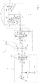
- einen schematischen Hydraulikplan einer Einrichtung zur Steuerung einer Auslassklappe einer Ballenpresse.
- In der
Figur 1 der Zeichnung wird eine schematisch dargestellte Ballenpresse 10, in der Art einer landwirtschaftlichen Rundballenpresse zum Pressen eines rundzylindrischen Ballens 12 gezeigt, welche einen Gehäuseteil 14 aufweist, der sich mittels Rädern 16 auf einem Untergrund 18 abstützt und die mittels einer Deichsel 20 an ein Zugfahrzeug 22, z. B. einen Ackerschlepper, anschließbar ist. - An einer bezogen auf eine Vorwärtsfahrtrichtung vorderen, unteren Seite des Gehäuseteils 14 befindet sich in bekannter Weise eine Aufnahmevorrichtung 24 zur Aufnahme und Zufuhr von Erntegut, die geschnittenes Erntegut in einen Pressraum 26 fördert, wobei der Gehäuseteil 14 einen vorderen Teil des Pressraum 26 umgibt. An dem rückwärtigen oberen Eckbereich des ersten Gehäuseteils 14 befindet sich ein Lager 28 für eine einen zweiten Gehäuseteil bildende schwenkbare Auslassklappe 30, die einen hinteren Teil des Pressraums 26 umgibt. Die Auslassklappe 30 gibt im geöffneten Zustand eine Öffnung 32 frei, durch welche ein von der Ballenpresse 10 gepresster Ballen 12 abgesetzt bzw. entladen oder ausgeworfen werden kann.
- Gemäß dem vorliegenden Ausführungsbeispiel ist der Pressraum 26 der Ballenpresse 10 größenunveränderlich ausgebildet und die Ballenpresse 10 weist eine Vielzahl zueinander parallel verlaufender Pressrollen 34 (exemplarisch wurden hier nur einige wenige Pressrollen 34 mit dem Bezugszeichen 34 versehen), deren Rollachsen 36 bei geschlossenem zweiten Gehäuseteil 24 auf einem Kreisbogen gelegen sind, und von denen wenigstens einige angetrieben sind. Die Pressrollen 36 dienen, neben einem Pressen und einer Formgebung, insbesondere auch einer Rotationserzeugung oder einer Rotationserhaltung des in dem Pressraum 20 angeordneten Rundballens 12. Die Ballenpresse 10 ist hier exemplarisch zur Darstellung der Öffnung 32 mit leicht geöffneter Auslassklappe 30 abgebildet.
- Es wird nun auch auf die
Figur 2 Bezug genommen, in der eine Einrichtung 38 zur Steuerung der Auslassklappe 30 in zumindest einem manuellen und einem automatischen Modus schematisch dargestellt wird. Gemäß dem vorliegenden Ausführungsbeispiel ist eine Druckquelle 40 vorgesehen, bei der es sich um eine Hydraulikpumpe des Zugfahrzeugs 22 handelt. Die Druckquelle 40 steht in konventioneller Weise mit einem Druckmittelreservoir 42 des Zugfahrzeugs 22 in Verbindung und liefert über ein Steuerventil 44, dass hier als elektromagnetisch betätigbares 4/3-Wegeventil mit vier Anschlüsse 44.1, 44.2, 44.3 und 44.4 ausgeführt ist, einen Hydraulikdruck für an das Zugfahrzeug 22 anschließbare Anbaugeräte, wie beispielsweise der hier beschriebenen Ballenpresse 10. Darüber hinaus ist in der Steuerungseinrichtung 38 in ebenfalls bekannter Weise ein Überdruckventil 46 vorgesehen, das öffnet, sollte in der Hydraulikkreis der Steuerungseinrichtung 38 ein Druck anstehen, der einen vergebenen Höchstdruck übersteigt. - Zur Betätigung der schwenkbaren Auslassklappe 30 sind an der Ballenpresse zwei gemeinsam ansteuerbare Schwenkantriebe bzw. Auslassklappenantriebe 48 vorgesehen, die in bekannter Art und Weise als doppeltwirkenden Hydraulikmotoren ausgebildet sind und erste Anschlüsse 48.1 und zweite Anschlüsse 48.2 aufweisen. Es ist aber auch denkbar, dass nur ein Auslassklappenantrieb 48 bzw. nur ein Hydraulikmotor vorgesehen ist. Die Auslassklappenantriebe 48 weisen jeweils einen Zylinder 50 und einen in dem Zylinder 50 verschiebbaren Kolben 52 auf, wobei der Kolben 52 den Zylinder 50 in einen ersten und einen zweiten Zylinderbereich 50a, 50b unterteilt. Den Auslassklappenantrieben 48 vorgelagert ist ein gemäß dem vorliegenden Ausführungsbeispiel manuell betätigbarer, arretierbarer Sperrschieber 54 mit Anschlüssen 54.1, 54.2 und 54.3 vorgesehen, mittels dem ein Hydraulikfluss zu und von den Schwenkantrieben 48 über deren Anschlüssen 48.1 und 48.2 erlaubt bzw. unterbunden werden kann.
- Das Steuerventil 44 kann wahlweise eine Stellung A, B oder C einnehmen, wobei in der ersten Stellung A eine ein erstes Druckmessmittel 56a aufweisende Druckleitung 58a über die Anschlüsse 44.1 und 44.2 mit Druck beaufschlagt wird. Nimmt das Steuerventil 44 seine dritte Stellung C ein, so wird eine zweite, ebenfalls ein Druckmessmittel 56b aufweisende Druckleitung 58b über die Anschlüsse 44.1 und 44.4 mit Druck beaufschlagt Nimmt das Steuerventil 44 seine mittlere Stellung bzw. seine Sperrstellung B ein, wird ein Hydraulikfluss unterbunden bzw. es wird keine der Druckleitungen 58a, b mit Druck beaufschlagt.
- Weiter ist ein Auslassklappen- bzw. Verteilerventil 60 vorgesehen, das als ein elektromagnetisch betätigbares 6/3-Wegeventil ausgebildet ist und sechs Anschlüsse 60.1, 60.2, 60.3, 60.4, 60.5 und 60.6 aufweist. Das Verteilerventil 60 ist zwischen den Druckmessmitteln 56a,b und dem Sperrschieber 54 vorgesehen und kann drei Stellungen, eine erste Durchlassstellung D, eine Sperrstellung E und eine zweite Durchlassstellung F einnehmen. In seiner ersten Durchlassstellung D verbindet das Verteilerventil 60 die erste Druckleitung 58a über seine Anschlüsse 60.1 und 60.4 mit dem ersten Anschluss 54.1 des Sperrschiebers 54 und über die zweiten Anschlüsse 54.2 und 54.3 des Sperrschiebers 54 mit den ersten Anschlüssen 48.1 der Schwenkantriebe 48. Über die Anschlüsse 60.2 und 60.5 wird eine Verbindung zwischen den zweiten Anschlüssen 48.2 der Auslassklappenantriebe 48 mit der zweiten Druckleitung 58b hergestellt. In seiner Sperrstellung E wird ein Hydraulikfluss zu und von den Auslassklappenantrieben 48 unterbunden und es wird über die Anschlüsse 60.3 und 60.6 eine Verbindung zwischen den Druckleitungen 58a und 58b hergestellt. In der zweiten Durchlassstellung F wird über die Anschlüsse 60.1 und 60.5 eine Verbindung mit dem ersten Anschluss 54.1 des Sperrschiebers 54 und über die zweiten Anschlüsse 54.2 und 54.3 des Sperrschiebers 54 mit den ersten Anschlüssen 48.1 der Auslassklappenantriebe 48 hergestellt. Über die Anschlüsse 60.2 und 60.4 werden die zweiten Anschlüssen 48.2 der Auslassklappenantriebe 48 mit der zweiten Druckleitung 58b verbunden.
- Darüber hinaus ist eine Steuer- bzw. Regeleinheit 62 zur Steuerung und/oder Regelung einzelner oder mehrerer Funktionen bzw. Abläufe der Ballenpresse 10 vorgesehen, über die das Verteilerventil 60 angesteuert werden kann. Die Steuerungseinheit 62 ist mit einer Betätigungseinrichtung 64 zur Aktivierung bzw. Deaktivierung eines Automatikmodus der Auslassklappe 30 und darüber hinaus mit den Druckmessmitteln 56a, b wirksam verbunden.
- Im Folgenden soll nun genauer auf die Funktionsweise der zuvor beschriebenen Einrichtung 38 eingegangen werden.
- Die Ballenpresse 10 kann in einem manuellen und einem automatischen Modus betrieben werden, der von einer Bedienungsperson über die vorzugsweise in einer Kabine des Zugfahrzeugs 22 angeordneten Betätigungseinrichtung 64 ausgewählt werden kann.
- Im manuellen Modus ist ein Neutralzustand vorgesehen, in dem das Steuerventil 44 seine Sperrstellung B und das Verteilerventil 60 seiner ersten Durchlassstellung D einnimmt. In diesem Neutralzustand wird keine der Druckleitungen 58a, b mit Druck beaufschlagt.
- Zum Öffnen der Auslassklappe 30 wird das Steuerventil 44 in bekannter Art und Weise angesteuert und nimmt seine Stellung A ein, in der die Druckleitung 58a mit Druck beaufschlagt wird. Das Verteilerventil 60 befindet sich unverändert in seiner ersten Durchlassstellung D, wodurch der Anschluss 48.1 des Auslassklappenantriebe 48 mit Druck beaufschlagt und die Kolben 52 der Auslassklappenantriebe 48 bezogen auf die Zylinder 50 ausgefahren werden, um die Auslassklappe 30 zu öffnen. Sich in den nun nicht mit Druck beaufschlagten Bereichen 48b der Zylinder 50 befindendes Druckmittel kann über die Anschlüsse 48.2 in Richtung des Druckmittelreservoirs 42 abfließen.
- Um die Auslassklappe 30 zu schließen, wird das Steuerventil 44 derart angesteuert, dass es seine Stellung C einnimmt und die Anschlüsse 48.2 der Auslassklappenantriebe 48 über die Druckleitung 58b und das sich weiterhin in seiner ersten Durchlassstellung D befindliche Verteilerventil 60 mit Druck beaufschlagt werden, so dass die Kolben 52 der Auslassklappenantriebe 48 bezogen auf die Zylinder 50 eingefahren werden, um die Auslassklappe 30 zu schließen. Sich in den nun nicht mit Druck beaufschlagten Bereichen 50a der Zylinder 50 befindendes Druckmittel kann nun in Richtung des Druckmittelreservoirs 42 abfließen.
- Um die Ballenpresse 10 bzw. die Steuerungseinrichtung 38 in einem automatischen Modus zu betreiben, muss zuerst das Steuerventil 44 in eine seiner aktiven Stellungen A oder C gebracht werden, in der eine der Druckleitungen 58a oder b mit Druck beaufschlagt wird.
- Im Anschluss kann durch eine Betätigung des Betätigungsschalters 64 der automatische Modus aktiviert werden, in dem die Steuerungseinrichtung 38 initial einen Neutralzustand einnimmt, in dem sich das Verteilerventil 60 in seiner Sperrstellung E befindet. Die Druckmessmittel 56a und b ermitteln nun einen jeweils einen in den Druckleitungen 58a bzw. b anstehenden Druck und übermitteln diese Information an die Steuereinrichtung 62. Darüber hinaus stehen der Steuereinrichtung 62 in bekannter Weise Informationen über den aktuellen Zustand der Ballepresse 10 zur Verfügung, insbesondere darüber, ob ein sich in der Ballenpresse 10 befindlicher Ballen 12 aus dem Pressraum 26 abgegeben werden soll, beispielsweise da ein Ballenbildungs- bzw. Ballenbindungs- und/oder Ballenumhüllungsprozess abgeschlossen ist.
- Liegt der Steuereinrichtung 62 nun die Information vor, dass der Ballen 12 aus dem Pressraum 26 abgeben werden soll, so steuert diese das Verteilerventil 60 in Abhängigkeit von einer zwischen den Druckmessmitteln 56a und b anstehenden Druckdifferenz derart an, dass es seine ersten Durchlassstellung D einnimmt, wenn sich das Steuerventil 44 in seiner Stellung A befindet und somit an dem Druckmessmittel 56a bzw. in der Druckleitung 58a ein höherer Druck ansteht als an dem Druckmessmittel 56b bzw. in der Druckleitung 56b. Befindet sich das Steuerventil 44 allerdings bei Aktivierung des automatischen Modus in seiner Stellung C liegt in der Druckleitung 58b bzw. an dem Druckmessmittel 56b ein höherer Druck an als in der Druckleitung 56a bzw. an dem Druckmessmittel 56a und die Steuereinrichtung 62 steuert das Verteilerventil 60 derart an, dass es seine zweite Durchlassstellung F einnimmt. Entsprechend beaufschlagt die Druckquelle 40 die Bereiche 50a der Zylinder 50 mit Druck. Die Kolben 52 fahren nun bezogen auf die Zylinder 50 aus und verschwenken gemäß dem gezeigten Ausführungsbeispiel die Auslassklappe 30 nach oben. Diese gibt nun die Öffnung 32 frei und der Ballen 12 kann den Pressraum 26 verlassen.
- Soll die Auslassklappe 30 (wieder) geschlossen werden, da der Ballen 12 den Pressraum 26 verlassen hat, was beispielsweise durch einen oder mehrere entsprechende Sensoren (beispielsweise nicht gezeigt Druck- oder Auflagesensoren) ermittelt werden kann, die beispielsweise an einer Entladerampe 66 (siehe
Figur 1 ) der Ballenpresse 10 angeordnet sein können, so steuert die Steuereinrichtung 62 das Verteilerventil 60 derart an, dass es seine Stellung F einnimmt, wenn das Steuerventil 44 sich in seiner Stellung A befindet und somit in der Druckleitung 58a bzw. an dem Druckmessmittel 56a ein höherer Druck ansteht als in der Druckleitung 58b bzw. an dem Druckmessmittel 56b. Befindet sich das Steuerventil 44 aber in seiner Stellung C und es liegt somit in der Druckleitung 58b bzw. an dem Druckmessmittel 56b ein höherer Druck an als in der Druckleitung 58a bzw. an dem Druckmessmittel 56a, so steuert die Steuereinrichtung 62 das Verteilerventil 60 derart an, dass es sein Stellung A einnimmt. - Ist ein Betrieb im automatischen Modus nicht länger gewünscht, kann dieser deaktiviert werden, in dem die Bedienungsperson den Betätigungsschalter 64 entsprechend betätigt bzw. in eine entsprechende Stellung bringt. Es ist darüber hinaus bzw. alternativ vorgesehen, dass die Steuereinrichtung 38 in den manuellen Modus zurückkehrt, wenn das das Steuerventil 44 während eines Betriebs im automatischen Modus, gegebenenfalls auch nur kurzfristig, in seine Sperrstellung B verbracht wird, in der es einen Druckmittelstrom von der Druckquelle 42 zu dem Verteilerventil 60 unterbindet. Die Druckmessmittel 56a, b ermitteln dann nicht länger eine Druckdifferenz zwischen den in den Druckleitungen 58a, b anstehenden Drücken und die Steuereinrichtung 62 steuert das Verteilerventil 62 derart an, dass es seine Stellung A und damit die Steuerungsanordnung 38 den zuvor beschriebenen Neutralzustand des manuellen Modus einnimmt. Dies kann insbesondere dann günstig sein, wenn die Ballenpresse 10 in Gelände unterschiedlicher Geländeformen eingesetzt wird, beispielsweise einem Gelände, in dem sich Hügel und flache Geländebereiche abwechseln. Hier, wie auch in einer Notfallsituation, kann es wichtig und/oder hilfreich sein, dass eine Bedienungsperson schnell und/oder kurzfristig die manuelle Kontrolle über ein Abgeben des Ballens aus dem Pressraum bzw. eines Schließens und/oder Öffnen einer Auslassklappe (zurück-) erlangen kann.
Claims (9)
- Einrichtung (38) zur Steuerung der Auslassklappe (30) einer Ballenpresse (10) in wenigstens einem manuellen und einem automatischen Modus mit einer ersten und einer zweiten Druckleitung (58a, b) über die ein Auslassklappenantrieb (48) selektiv mit Druck beaufschlagbar ist, dadurch gekennzeichnet, dass mit den Druckleitungen (58a, b) Druckmessmittel (56a, b) wirksam verbunden sind, die geeignet sind, einen jeweils in der Druckleitung (58a, b) anstehenden Druck zu ermitteln, und mit den Druckleitungen (58a, b) den Druckmessmitteln (56a, b) nachgeordnet ein wenigstens eine erste und eine zweiten Durchlassstellung (D, F) sowie eine Sperrstellung (E) aufweisendes Verteilerventil (60) verbunden ist, welches in dem wenigstens einen automatischen Modus in Abhängigkeit vom Wert einer Druckdifferenz zwischen den ermittelten Drücken eine vorbestimmte Stellung (D, E, F) einnimmt.
- Einrichtung nach Anspruch 1, dadurch gekennzeichnet, dass das Verteilerventil (60) in einer ersten Durchlassstellung (D, F) den Auslassklappenantrieb derart mit Druck beaufschlagt, dass dieser die Auslassklappe (30) in eine erste Position bringt, in der sie einen Pressraum (26) der Ballenpresse (10) zumindest im Wesentlichen verschließt, und in einer zweiten Durchlassstellung (D, F) den Auslassklappenantrieb (48) derart mit Druck beaufschlagt, dass dieser die Auslassklappe (30) in eine zweite Position bringt, in der sie vorzugsweise eine Öffnung (32) freigibt, durch den ein Ballen (12) den Pressraum (26) verlassen kann, wobei die erste Durchlassstellung (D, F) in dem automatischen Modus vorzugsweise mit einem Wert der Druckdifferenz mit einem ersten, insbesondere positiven bzw. negativen, Vorzeichen und die zweite Durchlassstellung (D, F) mit einem Wert der Druckdifferenz mit einem dem ersten entgegensetzen Vorzeichen korrespondiert.
- Einrichtung nach einem der vorherigen Ansprüche, dadurch gekennzeichnet, dass die Druckleitungen (58a b) derart ausgebildet sind, dass sie direkt oder indirekt an ein Steuerventil (44) eines Zugfahrzeugs (22) anschließbar sind, welches vorzugsweise derart mit einer Druckquelle (40) in Verbindung steht, dass es entweder die erste oder die zweite Druckleitung (58a, b) mit Druck beaufschlagen oder eine Sperrstellung (B) einnehmen kann, in der keine der Druckleitungen (58a, b) mit Druck beaufschlagt wird.
- Einrichtung nach einem der vorherigen Ansprüche, dadurch gekennzeichnet, dass der automatische Modus nur dann aktivierbar ist, wenn der Wert der Druckdifferenz nicht zumindest annähernd Null ist bzw. das Steuerventil (44) nicht seine Sperrstellung (B) einnimmt und/oder der automatische Modus automatisch deaktivierbar vorgesehen ist, insbesondere sobald der Wert der Druckdifferenz zumindest annähernd Null ist bzw. das Steuerventil (44) seine Sperrstellung (B) einnimmt.
- Einrichtung nach einem der vorherigen Ansprüche, dadurch gekennzeichnet, dass der Auslassklappenantrieb (48) zumindest einen Hydraulikmotor aufweist bzw. als ein solcher ausgebildet ist, wobei der Hydraulikmotor einen Zylinder (50) und einen in dem Zylinder (50) durch Beaufschlagung mit Druck in eine bezogen auf den Zylinder (50) eingefahrene und eine bezogen auf den Zylinder (50) ausgefahrene Stellung bringbaren Kolben (52) umfasst.
- Einrichtung nach einem der vorherigen Ansprüche, dadurch gekennzeichnet, dass eine Steuereinheit (62) zur direkten oder indirekten Ansteuerung zumindest des Verteilerventil (60) vorgesehen ist.
- Einrichtung nach einem der vorherigen Ansprüche, dadurch gekennzeichnet, dass eine Betätigungseinrichtung (64) zur Wahl wenigstens eines manuellen und eines automatischen Modus vorgesehen ist, die vorzugsweise mit einer/der Steuereinheit (62) wirksam verbindbar ist.
- Ballenpresse (10) mit einer Auslassklappe (30), die mittels eines Auslassklappenantriebs (48) zumindest in eine erste Position, in der die Auslassklappe (30) einen Pressraum (26) der Ballenpresse (10) zumindest im Wesentlichen verschließt und in eine zweite Position bringbar ist, in der sie eine Öffnung (32) freigibt, durch die ein Ballen (12) den Pressraum (26) der Ballenpresse (10) verlassen kann, gekennzeichnet durch eine Einrichtung (38) nach einem der Ansprüche 1 bis 7.
- Verfahren zur Steuerung der Auslassklappe (30) einer Ballenpresse (10) gemäß Anspruch 8 in wenigstens einem manuellen und einem automatischen Modus, dadurch gekennzeichnet, dass die Druckmessmittel (56a, b) einen jeweils in der Druckleitung (58a, b) anstehenden Druck ermitteln, und das Verteilerventil (60) zumindest in dem wenigstens einen automatischen Modus in Abhängigkeit vom Wert einer Differenz zwischen den ermittelten Drücken eine vorbestimmte Stellung (D, E, F) einnimmt.
Applications Claiming Priority (1)
| Application Number | Priority Date | Filing Date | Title |
|---|---|---|---|
| DE102017213436.4A DE102017213436A1 (de) | 2017-08-02 | 2017-08-02 | Einrichtung zur Steuerung der Auslassklappe einer Ballenpresse, Ballenpresse und Verfahren |
Publications (2)
| Publication Number | Publication Date |
|---|---|
| EP3437458A1 true EP3437458A1 (de) | 2019-02-06 |
| EP3437458B1 EP3437458B1 (de) | 2020-09-23 |
Family
ID=62916585
Family Applications (1)
| Application Number | Title | Priority Date | Filing Date |
|---|---|---|---|
| EP18183011.8A Active EP3437458B1 (de) | 2017-08-02 | 2018-07-11 | Einrichtung zur steuerung der auslassklappe einer ballenpresse, ballenpresse und verfahren |
Country Status (5)
| Country | Link |
|---|---|
| US (1) | US10334787B2 (de) |
| EP (1) | EP3437458B1 (de) |
| KR (1) | KR102600714B1 (de) |
| CN (1) | CN109383868B (de) |
| DE (1) | DE102017213436A1 (de) |
Families Citing this family (1)
| Publication number | Priority date | Publication date | Assignee | Title |
|---|---|---|---|---|
| IT201700093544A1 (it) | 2017-08-11 | 2019-02-11 | Kverneland Group Ravenna Srl | Imballatore connettibile ad un trattore per realizzare balle rotonde e metodo per realizzare balle rotonde |
Citations (4)
| Publication number | Priority date | Publication date | Assignee | Title |
|---|---|---|---|---|
| EP2042028A1 (de) | 2007-09-28 | 2009-04-01 | Deere & Company | Sequenz- und Zeitgabesteuerung für Vorrichtung zum Ausstoßen großer runder Ballen |
| EP2923560A1 (de) * | 2014-03-25 | 2015-09-30 | CNH Industrial Belgium nv | Ballenpresssystem mit ballenpositionssensor |
| AU2012307238B2 (en) * | 2011-09-14 | 2016-10-27 | Maricap Oy | Method and apparatus for handling material in a pneumatic pipe transport system |
| EP3150061A1 (de) * | 2015-09-30 | 2017-04-05 | Deere & Company | Hydraulisches system mit landwirtschaftlicher ausrüstung und verfahren dafür |
Family Cites Families (16)
| Publication number | Priority date | Publication date | Assignee | Title |
|---|---|---|---|---|
| FR2513775A1 (fr) * | 1980-05-28 | 1983-04-01 | Comagref | Procede d'entretien d'un mouvement d'oscillation, son application aux dispositifs oscillants a force d'entretien par fluide hydraulique haute pression et presse, notamment presse a pailles, comportant un tel dispositif oscillant |
| FR2643785B1 (fr) * | 1989-03-03 | 1992-02-07 | Hesston Braud | Procede et dispositif de regulation de densite pour ramasseuse-presse a balles parallelepipediques |
| US5622104A (en) * | 1995-08-28 | 1997-04-22 | Gehl Company | Cylindrical baler having hydraulic circuit for controlling bale density and tailgate operation |
| EP1018292B8 (de) * | 1999-01-09 | 2005-06-29 | GKN Walterscheid GmbH | Hubwerk für die Unterlenker einer Anbauvorrichtung eines Traktors |
| US6272825B1 (en) * | 1999-09-15 | 2001-08-14 | Hay & Forage Industries | Round baler having hydraulically sequenced clutch and tailgate cylinders |
| DE10303201C5 (de) | 2003-01-28 | 2015-03-12 | Lely Vermeer Maschinenfabrik GmbH | Rundballenpresse für landwirtschaftliche Halmgüter |
| US20070234908A1 (en) * | 2006-04-10 | 2007-10-11 | James Hines | Multiple Baler System |
| CN101318568A (zh) * | 2007-06-05 | 2008-12-10 | 何塞·C·G·洛佩斯 | 固定可膨胀纤维捆包的系统及应用该系统的捆包 |
| CA2630199A1 (en) * | 2008-05-01 | 2009-11-01 | Multimatic Inc. | Vehicle auxiliary hydraulic system |
| US7849791B2 (en) * | 2008-11-10 | 2010-12-14 | Cnh America Llc | Optimized baler tailgate cycle |
| CN202137968U (zh) * | 2011-06-08 | 2012-02-08 | 锦州辽能生物质能源开发有限公司 | 秸秆压捆机 |
| CN102598964A (zh) * | 2012-03-20 | 2012-07-25 | 王连 | 秸秆收集运输车的压实打包装置 |
| CN203040228U (zh) * | 2013-02-20 | 2013-07-10 | 中机美诺科技股份有限公司 | 一种适用于捡拾圆捆机的可调节草捆密度的液压控制装置 |
| US9107348B2 (en) * | 2013-11-25 | 2015-08-18 | Cnh Industrial America Llc | Fluid circuit for bale ejection |
| US9241443B2 (en) * | 2014-03-13 | 2016-01-26 | Deere & Company | Gate position control of round bale discharge |
| CN106884816B (zh) * | 2017-03-21 | 2018-06-26 | 江苏大学 | 一种圆捆打捆机喂料口开度自适应控制系统及其控制方法 |
-
2017
- 2017-08-02 DE DE102017213436.4A patent/DE102017213436A1/de not_active Withdrawn
-
2018
- 2018-07-02 CN CN201810706797.5A patent/CN109383868B/zh active Active
- 2018-07-11 EP EP18183011.8A patent/EP3437458B1/de active Active
- 2018-07-25 KR KR1020180086451A patent/KR102600714B1/ko active Active
- 2018-07-25 US US16/044,540 patent/US10334787B2/en active Active
Patent Citations (4)
| Publication number | Priority date | Publication date | Assignee | Title |
|---|---|---|---|---|
| EP2042028A1 (de) | 2007-09-28 | 2009-04-01 | Deere & Company | Sequenz- und Zeitgabesteuerung für Vorrichtung zum Ausstoßen großer runder Ballen |
| AU2012307238B2 (en) * | 2011-09-14 | 2016-10-27 | Maricap Oy | Method and apparatus for handling material in a pneumatic pipe transport system |
| EP2923560A1 (de) * | 2014-03-25 | 2015-09-30 | CNH Industrial Belgium nv | Ballenpresssystem mit ballenpositionssensor |
| EP3150061A1 (de) * | 2015-09-30 | 2017-04-05 | Deere & Company | Hydraulisches system mit landwirtschaftlicher ausrüstung und verfahren dafür |
Also Published As
| Publication number | Publication date |
|---|---|
| EP3437458B1 (de) | 2020-09-23 |
| CN109383868A (zh) | 2019-02-26 |
| KR20190014468A (ko) | 2019-02-12 |
| DE102017213436A1 (de) | 2019-02-07 |
| CN109383868B (zh) | 2022-06-03 |
| US20190037775A1 (en) | 2019-02-07 |
| US10334787B2 (en) | 2019-07-02 |
| KR102600714B1 (ko) | 2023-11-13 |
Similar Documents
| Publication | Publication Date | Title |
|---|---|---|
| EP2067399B1 (de) | Anordnung zur Verstellung der Position einer Aufnehmertrommel und eines Niederhalters einer landwirtschaftlichen Erntemaschine | |
| DE69607969T4 (de) | Rundballenpresse mit veränderlichem pressraum und ein pressraum mit veränderlicher geometrie um ballenkerne zu formen | |
| EP0104510B1 (de) | Ballenschiebevorrichtung für eine Rundballenpresse | |
| EP2689654B1 (de) | Fördervorrichtung und Ballenpresse mit einer solchen | |
| DE10303201B4 (de) | Rundballenpresse für landwirtschaftliche Halmgüter | |
| EP3900517A1 (de) | Rundballenpresse und verfahren zum betrieb einer rundballenpresse | |
| DE19718229A1 (de) | Landwirtschaftliche Rundballenpresse | |
| EP1230837B1 (de) | Rundballenpresse | |
| EP1366654B1 (de) | Rundballenpresse | |
| EP2984922A1 (de) | Ballenwickeleinrichtung | |
| EP3437458B1 (de) | Einrichtung zur steuerung der auslassklappe einer ballenpresse, ballenpresse und verfahren | |
| DE60004936T2 (de) | Vorrichtung und Verfahren zur Positionierung lenkbarere Räder | |
| EP3560323B1 (de) | Landwirtschaftliche rundballenpresse und verfahren zum betrieb einer landwirtschaftlichen rundballenpresse | |
| DE29911916U1 (de) | Wickelvorrichtung und System zum Pressen und Wickeln von Ballen | |
| DE4031590C1 (de) | ||
| DE10212722A1 (de) | Erntemaschine | |
| EP4129045B1 (de) | Rundballenpresse und verfahren zum öffnen einer auswurfklappe einer rundballenpresse | |
| EP1446998A1 (de) | Vorrichtung zum Unterstützen des Austritts eines Rundballens | |
| EP1595439B1 (de) | Maschine zum Aufnehmen und Pressen von landwirtschaftlichem Erntegut | |
| EP3760031B1 (de) | Rundballenpresse und verfahren zum betrieb einer rundballenpresse | |
| DE2517340A1 (de) | Rollballenpresse fuer landwirtschaftliche halmgueter mit zweiteiligem pressraumgehaeuse | |
| EP1595440B1 (de) | Maschine zum Aufnehmen und Pressen von landwirtschaftlichem Erntegut | |
| EP3771322B1 (de) | Landwirtschaftliche maschine | |
| EP3420805B1 (de) | Umhüllungseinrichtung, blockiereinrichtung, ballenpresse und verfahren zur anpassung einer ballenpresse an ein hüllmaterial | |
| DE102022134299A1 (de) | Landwirtschaftliche Ballenpresse |
Legal Events
| Date | Code | Title | Description |
|---|---|---|---|
| PUAI | Public reference made under article 153(3) epc to a published international application that has entered the european phase |
Free format text: ORIGINAL CODE: 0009012 |
|
| STAA | Information on the status of an ep patent application or granted ep patent |
Free format text: STATUS: THE APPLICATION HAS BEEN PUBLISHED |
|
| AK | Designated contracting states |
Kind code of ref document: A1 Designated state(s): AL AT BE BG CH CY CZ DE DK EE ES FI FR GB GR HR HU IE IS IT LI LT LU LV MC MK MT NL NO PL PT RO RS SE SI SK SM TR |
|
| AX | Request for extension of the european patent |
Extension state: BA ME |
|
| STAA | Information on the status of an ep patent application or granted ep patent |
Free format text: STATUS: REQUEST FOR EXAMINATION WAS MADE |
|
| 17P | Request for examination filed |
Effective date: 20190814 |
|
| RBV | Designated contracting states (corrected) |
Designated state(s): AL AT BE BG CH CY CZ DE DK EE ES FI FR GB GR HR HU IE IS IT LI LT LU LV MC MK MT NL NO PL PT RO RS SE SI SK SM TR |
|
| GRAP | Despatch of communication of intention to grant a patent |
Free format text: ORIGINAL CODE: EPIDOSNIGR1 |
|
| STAA | Information on the status of an ep patent application or granted ep patent |
Free format text: STATUS: GRANT OF PATENT IS INTENDED |
|
| INTG | Intention to grant announced |
Effective date: 20200506 |
|
| GRAS | Grant fee paid |
Free format text: ORIGINAL CODE: EPIDOSNIGR3 |
|
| GRAA | (expected) grant |
Free format text: ORIGINAL CODE: 0009210 |
|
| STAA | Information on the status of an ep patent application or granted ep patent |
Free format text: STATUS: THE PATENT HAS BEEN GRANTED |
|
| AK | Designated contracting states |
Kind code of ref document: B1 Designated state(s): AL AT BE BG CH CY CZ DE DK EE ES FI FR GB GR HR HU IE IS IT LI LT LU LV MC MK MT NL NO PL PT RO RS SE SI SK SM TR |
|
| REG | Reference to a national code |
Ref country code: GB Ref legal event code: FG4D Free format text: NOT ENGLISH |
|
| REG | Reference to a national code |
Ref country code: CH Ref legal event code: EP |
|
| REG | Reference to a national code |
Ref country code: DE Ref legal event code: R096 Ref document number: 502018002521 Country of ref document: DE |
|
| REG | Reference to a national code |
Ref country code: IE Ref legal event code: FG4D Free format text: LANGUAGE OF EP DOCUMENT: GERMAN |
|
| REG | Reference to a national code |
Ref country code: AT Ref legal event code: REF Ref document number: 1315421 Country of ref document: AT Kind code of ref document: T Effective date: 20201015 |
|
| PG25 | Lapsed in a contracting state [announced via postgrant information from national office to epo] |
Ref country code: HR Free format text: LAPSE BECAUSE OF FAILURE TO SUBMIT A TRANSLATION OF THE DESCRIPTION OR TO PAY THE FEE WITHIN THE PRESCRIBED TIME-LIMIT Effective date: 20200923 Ref country code: SE Free format text: LAPSE BECAUSE OF FAILURE TO SUBMIT A TRANSLATION OF THE DESCRIPTION OR TO PAY THE FEE WITHIN THE PRESCRIBED TIME-LIMIT Effective date: 20200923 Ref country code: GR Free format text: LAPSE BECAUSE OF FAILURE TO SUBMIT A TRANSLATION OF THE DESCRIPTION OR TO PAY THE FEE WITHIN THE PRESCRIBED TIME-LIMIT Effective date: 20201224 Ref country code: FI Free format text: LAPSE BECAUSE OF FAILURE TO SUBMIT A TRANSLATION OF THE DESCRIPTION OR TO PAY THE FEE WITHIN THE PRESCRIBED TIME-LIMIT Effective date: 20200923 Ref country code: NO Free format text: LAPSE BECAUSE OF FAILURE TO SUBMIT A TRANSLATION OF THE DESCRIPTION OR TO PAY THE FEE WITHIN THE PRESCRIBED TIME-LIMIT Effective date: 20201223 Ref country code: BG Free format text: LAPSE BECAUSE OF FAILURE TO SUBMIT A TRANSLATION OF THE DESCRIPTION OR TO PAY THE FEE WITHIN THE PRESCRIBED TIME-LIMIT Effective date: 20201223 |
|
| PG25 | Lapsed in a contracting state [announced via postgrant information from national office to epo] |
Ref country code: LV Free format text: LAPSE BECAUSE OF FAILURE TO SUBMIT A TRANSLATION OF THE DESCRIPTION OR TO PAY THE FEE WITHIN THE PRESCRIBED TIME-LIMIT Effective date: 20200923 Ref country code: RS Free format text: LAPSE BECAUSE OF FAILURE TO SUBMIT A TRANSLATION OF THE DESCRIPTION OR TO PAY THE FEE WITHIN THE PRESCRIBED TIME-LIMIT Effective date: 20200923 |
|
| REG | Reference to a national code |
Ref country code: NL Ref legal event code: MP Effective date: 20200923 |
|
| REG | Reference to a national code |
Ref country code: LT Ref legal event code: MG4D |
|
| PG25 | Lapsed in a contracting state [announced via postgrant information from national office to epo] |
Ref country code: LT Free format text: LAPSE BECAUSE OF FAILURE TO SUBMIT A TRANSLATION OF THE DESCRIPTION OR TO PAY THE FEE WITHIN THE PRESCRIBED TIME-LIMIT Effective date: 20200923 Ref country code: SM Free format text: LAPSE BECAUSE OF FAILURE TO SUBMIT A TRANSLATION OF THE DESCRIPTION OR TO PAY THE FEE WITHIN THE PRESCRIBED TIME-LIMIT Effective date: 20200923 Ref country code: EE Free format text: LAPSE BECAUSE OF FAILURE TO SUBMIT A TRANSLATION OF THE DESCRIPTION OR TO PAY THE FEE WITHIN THE PRESCRIBED TIME-LIMIT Effective date: 20200923 Ref country code: CZ Free format text: LAPSE BECAUSE OF FAILURE TO SUBMIT A TRANSLATION OF THE DESCRIPTION OR TO PAY THE FEE WITHIN THE PRESCRIBED TIME-LIMIT Effective date: 20200923 Ref country code: PT Free format text: LAPSE BECAUSE OF FAILURE TO SUBMIT A TRANSLATION OF THE DESCRIPTION OR TO PAY THE FEE WITHIN THE PRESCRIBED TIME-LIMIT Effective date: 20210125 Ref country code: RO Free format text: LAPSE BECAUSE OF FAILURE TO SUBMIT A TRANSLATION OF THE DESCRIPTION OR TO PAY THE FEE WITHIN THE PRESCRIBED TIME-LIMIT Effective date: 20200923 |
|
| PG25 | Lapsed in a contracting state [announced via postgrant information from national office to epo] |
Ref country code: IS Free format text: LAPSE BECAUSE OF FAILURE TO SUBMIT A TRANSLATION OF THE DESCRIPTION OR TO PAY THE FEE WITHIN THE PRESCRIBED TIME-LIMIT Effective date: 20210123 Ref country code: PL Free format text: LAPSE BECAUSE OF FAILURE TO SUBMIT A TRANSLATION OF THE DESCRIPTION OR TO PAY THE FEE WITHIN THE PRESCRIBED TIME-LIMIT Effective date: 20200923 Ref country code: AL Free format text: LAPSE BECAUSE OF FAILURE TO SUBMIT A TRANSLATION OF THE DESCRIPTION OR TO PAY THE FEE WITHIN THE PRESCRIBED TIME-LIMIT Effective date: 20200923 Ref country code: ES Free format text: LAPSE BECAUSE OF FAILURE TO SUBMIT A TRANSLATION OF THE DESCRIPTION OR TO PAY THE FEE WITHIN THE PRESCRIBED TIME-LIMIT Effective date: 20200923 |
|
| REG | Reference to a national code |
Ref country code: DE Ref legal event code: R097 Ref document number: 502018002521 Country of ref document: DE |
|
| PG25 | Lapsed in a contracting state [announced via postgrant information from national office to epo] |
Ref country code: SK Free format text: LAPSE BECAUSE OF FAILURE TO SUBMIT A TRANSLATION OF THE DESCRIPTION OR TO PAY THE FEE WITHIN THE PRESCRIBED TIME-LIMIT Effective date: 20200923 |
|
| PLBE | No opposition filed within time limit |
Free format text: ORIGINAL CODE: 0009261 |
|
| STAA | Information on the status of an ep patent application or granted ep patent |
Free format text: STATUS: NO OPPOSITION FILED WITHIN TIME LIMIT |
|
| PG25 | Lapsed in a contracting state [announced via postgrant information from national office to epo] |
Ref country code: SI Free format text: LAPSE BECAUSE OF FAILURE TO SUBMIT A TRANSLATION OF THE DESCRIPTION OR TO PAY THE FEE WITHIN THE PRESCRIBED TIME-LIMIT Effective date: 20200923 Ref country code: DK Free format text: LAPSE BECAUSE OF FAILURE TO SUBMIT A TRANSLATION OF THE DESCRIPTION OR TO PAY THE FEE WITHIN THE PRESCRIBED TIME-LIMIT Effective date: 20200923 |
|
| 26N | No opposition filed |
Effective date: 20210624 |
|
| PG25 | Lapsed in a contracting state [announced via postgrant information from national office to epo] |
Ref country code: IT Free format text: LAPSE BECAUSE OF FAILURE TO SUBMIT A TRANSLATION OF THE DESCRIPTION OR TO PAY THE FEE WITHIN THE PRESCRIBED TIME-LIMIT Effective date: 20200923 |
|
| REG | Reference to a national code |
Ref country code: CH Ref legal event code: PL |
|
| PG25 | Lapsed in a contracting state [announced via postgrant information from national office to epo] |
Ref country code: MC Free format text: LAPSE BECAUSE OF FAILURE TO SUBMIT A TRANSLATION OF THE DESCRIPTION OR TO PAY THE FEE WITHIN THE PRESCRIBED TIME-LIMIT Effective date: 20200923 |
|
| REG | Reference to a national code |
Ref country code: BE Ref legal event code: MM Effective date: 20210731 |
|
| PG25 | Lapsed in a contracting state [announced via postgrant information from national office to epo] |
Ref country code: LI Free format text: LAPSE BECAUSE OF NON-PAYMENT OF DUE FEES Effective date: 20210731 Ref country code: CH Free format text: LAPSE BECAUSE OF NON-PAYMENT OF DUE FEES Effective date: 20210731 |
|
| PG25 | Lapsed in a contracting state [announced via postgrant information from national office to epo] |
Ref country code: LU Free format text: LAPSE BECAUSE OF NON-PAYMENT OF DUE FEES Effective date: 20210711 |
|
| PG25 | Lapsed in a contracting state [announced via postgrant information from national office to epo] |
Ref country code: BE Free format text: LAPSE BECAUSE OF NON-PAYMENT OF DUE FEES Effective date: 20210731 |
|
| GBPC | Gb: european patent ceased through non-payment of renewal fee |
Effective date: 20220711 |
|
| PG25 | Lapsed in a contracting state [announced via postgrant information from national office to epo] |
Ref country code: GB Free format text: LAPSE BECAUSE OF NON-PAYMENT OF DUE FEES Effective date: 20220711 |
|
| PG25 | Lapsed in a contracting state [announced via postgrant information from national office to epo] |
Ref country code: NL Free format text: LAPSE BECAUSE OF NON-PAYMENT OF DUE FEES Effective date: 20200923 Ref country code: CY Free format text: LAPSE BECAUSE OF FAILURE TO SUBMIT A TRANSLATION OF THE DESCRIPTION OR TO PAY THE FEE WITHIN THE PRESCRIBED TIME-LIMIT Effective date: 20200923 |
|
| PG25 | Lapsed in a contracting state [announced via postgrant information from national office to epo] |
Ref country code: HU Free format text: LAPSE BECAUSE OF FAILURE TO SUBMIT A TRANSLATION OF THE DESCRIPTION OR TO PAY THE FEE WITHIN THE PRESCRIBED TIME-LIMIT; INVALID AB INITIO Effective date: 20180711 |
|
| PG25 | Lapsed in a contracting state [announced via postgrant information from national office to epo] |
Ref country code: MK Free format text: LAPSE BECAUSE OF FAILURE TO SUBMIT A TRANSLATION OF THE DESCRIPTION OR TO PAY THE FEE WITHIN THE PRESCRIBED TIME-LIMIT Effective date: 20200923 |
|
| REG | Reference to a national code |
Ref country code: AT Ref legal event code: MM01 Ref document number: 1315421 Country of ref document: AT Kind code of ref document: T Effective date: 20230711 |
|
| PG25 | Lapsed in a contracting state [announced via postgrant information from national office to epo] |
Ref country code: MT Free format text: LAPSE BECAUSE OF FAILURE TO SUBMIT A TRANSLATION OF THE DESCRIPTION OR TO PAY THE FEE WITHIN THE PRESCRIBED TIME-LIMIT Effective date: 20200923 |
|
| PG25 | Lapsed in a contracting state [announced via postgrant information from national office to epo] |
Ref country code: AT Free format text: LAPSE BECAUSE OF NON-PAYMENT OF DUE FEES Effective date: 20230711 |
|
| PG25 | Lapsed in a contracting state [announced via postgrant information from national office to epo] |
Ref country code: AT Free format text: LAPSE BECAUSE OF NON-PAYMENT OF DUE FEES Effective date: 20230711 |
|
| PGFP | Annual fee paid to national office [announced via postgrant information from national office to epo] |
Ref country code: DE Payment date: 20250620 Year of fee payment: 8 |
|
| PGFP | Annual fee paid to national office [announced via postgrant information from national office to epo] |
Ref country code: FR Payment date: 20250725 Year of fee payment: 8 |
|
| PGFP | Annual fee paid to national office [announced via postgrant information from national office to epo] |
Ref country code: IE Payment date: 20250728 Year of fee payment: 8 |
|
| PG25 | Lapsed in a contracting state [announced via postgrant information from national office to epo] |
Ref country code: TR Free format text: LAPSE BECAUSE OF FAILURE TO SUBMIT A TRANSLATION OF THE DESCRIPTION OR TO PAY THE FEE WITHIN THE PRESCRIBED TIME-LIMIT Effective date: 20200923 |
|
| PGFP | Annual fee paid to national office [announced via postgrant information from national office to epo] |
Ref country code: AT Payment date: 20260410 Year of fee payment: 5 |