EP3437090B1 - Modélisation adaptative de trajet secondaire dans un système de régulation de bruit actif - Google Patents
Modélisation adaptative de trajet secondaire dans un système de régulation de bruit actif Download PDFInfo
- Publication number
- EP3437090B1 EP3437090B1 EP17716715.2A EP17716715A EP3437090B1 EP 3437090 B1 EP3437090 B1 EP 3437090B1 EP 17716715 A EP17716715 A EP 17716715A EP 3437090 B1 EP3437090 B1 EP 3437090B1
- Authority
- EP
- European Patent Office
- Prior art keywords
- filter
- noise control
- active noise
- control system
- coefficients
- Prior art date
- Legal status (The legal status is an assumption and is not a legal conclusion. Google has not performed a legal analysis and makes no representation as to the accuracy of the status listed.)
- Active
Links
- 230000003044 adaptive effect Effects 0.000 title claims description 103
- 238000000034 method Methods 0.000 claims description 32
- 230000008569 process Effects 0.000 claims description 20
- 230000000694 effects Effects 0.000 claims description 8
- 238000001514 detection method Methods 0.000 claims description 7
- 230000000875 corresponding effect Effects 0.000 description 26
- 230000006870 function Effects 0.000 description 14
- 238000010586 diagram Methods 0.000 description 10
- 238000005516 engineering process Methods 0.000 description 8
- 230000004044 response Effects 0.000 description 8
- 230000008859 change Effects 0.000 description 6
- 238000004590 computer program Methods 0.000 description 6
- 230000003595 spectral effect Effects 0.000 description 5
- 230000002159 abnormal effect Effects 0.000 description 3
- 230000008901 benefit Effects 0.000 description 3
- 230000009467 reduction Effects 0.000 description 3
- 230000005534 acoustic noise Effects 0.000 description 2
- 230000006978 adaptation Effects 0.000 description 2
- 230000002411 adverse Effects 0.000 description 2
- 210000000613 ear canal Anatomy 0.000 description 2
- 239000011159 matrix material Substances 0.000 description 2
- PXFBZOLANLWPMH-UHFFFAOYSA-N 16-Epiaffinine Natural products C1C(C2=CC=CC=C2N2)=C2C(=O)CC2C(=CC)CN(C)C1C2CO PXFBZOLANLWPMH-UHFFFAOYSA-N 0.000 description 1
- 230000009471 action Effects 0.000 description 1
- 230000002238 attenuated effect Effects 0.000 description 1
- 230000001276 controlling effect Effects 0.000 description 1
- 230000002596 correlated effect Effects 0.000 description 1
- 238000000354 decomposition reaction Methods 0.000 description 1
- 239000006260 foam Substances 0.000 description 1
- 238000004519 manufacturing process Methods 0.000 description 1
- 230000007246 mechanism Effects 0.000 description 1
- 230000004048 modification Effects 0.000 description 1
- 238000012986 modification Methods 0.000 description 1
- 230000000737 periodic effect Effects 0.000 description 1
- 230000008672 reprogramming Effects 0.000 description 1
- 238000007493 shaping process Methods 0.000 description 1
- 238000004088 simulation Methods 0.000 description 1
- 239000007779 soft material Substances 0.000 description 1
- 230000005236 sound signal Effects 0.000 description 1
- 230000009466 transformation Effects 0.000 description 1
Images


Classifications
-
- F—MECHANICAL ENGINEERING; LIGHTING; HEATING; WEAPONS; BLASTING
- F01—MACHINES OR ENGINES IN GENERAL; ENGINE PLANTS IN GENERAL; STEAM ENGINES
- F01N—GAS-FLOW SILENCERS OR EXHAUST APPARATUS FOR MACHINES OR ENGINES IN GENERAL; GAS-FLOW SILENCERS OR EXHAUST APPARATUS FOR INTERNAL COMBUSTION ENGINES
- F01N1/00—Silencing apparatus characterised by method of silencing
- F01N1/06—Silencing apparatus characterised by method of silencing by using interference effect
- F01N1/065—Silencing apparatus characterised by method of silencing by using interference effect by using an active noise source, e.g. speakers
-
- G—PHYSICS
- G10—MUSICAL INSTRUMENTS; ACOUSTICS
- G10K—SOUND-PRODUCING DEVICES; METHODS OR DEVICES FOR PROTECTING AGAINST, OR FOR DAMPING, NOISE OR OTHER ACOUSTIC WAVES IN GENERAL; ACOUSTICS NOT OTHERWISE PROVIDED FOR
- G10K11/00—Methods or devices for transmitting, conducting or directing sound in general; Methods or devices for protecting against, or for damping, noise or other acoustic waves in general
- G10K11/16—Methods or devices for protecting against, or for damping, noise or other acoustic waves in general
- G10K11/175—Methods or devices for protecting against, or for damping, noise or other acoustic waves in general using interference effects; Masking sound
- G10K11/178—Methods or devices for protecting against, or for damping, noise or other acoustic waves in general using interference effects; Masking sound by electro-acoustically regenerating the original acoustic waves in anti-phase
- G10K11/1781—Methods or devices for protecting against, or for damping, noise or other acoustic waves in general using interference effects; Masking sound by electro-acoustically regenerating the original acoustic waves in anti-phase characterised by the analysis of input or output signals, e.g. frequency range, modes, transfer functions
- G10K11/17813—Methods or devices for protecting against, or for damping, noise or other acoustic waves in general using interference effects; Masking sound by electro-acoustically regenerating the original acoustic waves in anti-phase characterised by the analysis of input or output signals, e.g. frequency range, modes, transfer functions characterised by the analysis of the acoustic paths, e.g. estimating, calibrating or testing of transfer functions or cross-terms
- G10K11/17817—Methods or devices for protecting against, or for damping, noise or other acoustic waves in general using interference effects; Masking sound by electro-acoustically regenerating the original acoustic waves in anti-phase characterised by the analysis of input or output signals, e.g. frequency range, modes, transfer functions characterised by the analysis of the acoustic paths, e.g. estimating, calibrating or testing of transfer functions or cross-terms between the output signals and the error signals, i.e. secondary path
-
- G—PHYSICS
- G10—MUSICAL INSTRUMENTS; ACOUSTICS
- G10K—SOUND-PRODUCING DEVICES; METHODS OR DEVICES FOR PROTECTING AGAINST, OR FOR DAMPING, NOISE OR OTHER ACOUSTIC WAVES IN GENERAL; ACOUSTICS NOT OTHERWISE PROVIDED FOR
- G10K11/00—Methods or devices for transmitting, conducting or directing sound in general; Methods or devices for protecting against, or for damping, noise or other acoustic waves in general
- G10K11/16—Methods or devices for protecting against, or for damping, noise or other acoustic waves in general
- G10K11/175—Methods or devices for protecting against, or for damping, noise or other acoustic waves in general using interference effects; Masking sound
- G10K11/178—Methods or devices for protecting against, or for damping, noise or other acoustic waves in general using interference effects; Masking sound by electro-acoustically regenerating the original acoustic waves in anti-phase
- G10K11/1781—Methods or devices for protecting against, or for damping, noise or other acoustic waves in general using interference effects; Masking sound by electro-acoustically regenerating the original acoustic waves in anti-phase characterised by the analysis of input or output signals, e.g. frequency range, modes, transfer functions
- G10K11/17821—Methods or devices for protecting against, or for damping, noise or other acoustic waves in general using interference effects; Masking sound by electro-acoustically regenerating the original acoustic waves in anti-phase characterised by the analysis of input or output signals, e.g. frequency range, modes, transfer functions characterised by the analysis of the input signals only
- G10K11/17825—Error signals
-
- G—PHYSICS
- G10—MUSICAL INSTRUMENTS; ACOUSTICS
- G10K—SOUND-PRODUCING DEVICES; METHODS OR DEVICES FOR PROTECTING AGAINST, OR FOR DAMPING, NOISE OR OTHER ACOUSTIC WAVES IN GENERAL; ACOUSTICS NOT OTHERWISE PROVIDED FOR
- G10K11/00—Methods or devices for transmitting, conducting or directing sound in general; Methods or devices for protecting against, or for damping, noise or other acoustic waves in general
- G10K11/16—Methods or devices for protecting against, or for damping, noise or other acoustic waves in general
- G10K11/175—Methods or devices for protecting against, or for damping, noise or other acoustic waves in general using interference effects; Masking sound
- G10K11/178—Methods or devices for protecting against, or for damping, noise or other acoustic waves in general using interference effects; Masking sound by electro-acoustically regenerating the original acoustic waves in anti-phase
- G10K11/1783—Methods or devices for protecting against, or for damping, noise or other acoustic waves in general using interference effects; Masking sound by electro-acoustically regenerating the original acoustic waves in anti-phase handling or detecting of non-standard events or conditions, e.g. changing operating modes under specific operating conditions
- G10K11/17833—Methods or devices for protecting against, or for damping, noise or other acoustic waves in general using interference effects; Masking sound by electro-acoustically regenerating the original acoustic waves in anti-phase handling or detecting of non-standard events or conditions, e.g. changing operating modes under specific operating conditions by using a self-diagnostic function or a malfunction prevention function, e.g. detecting abnormal output levels
-
- G—PHYSICS
- G10—MUSICAL INSTRUMENTS; ACOUSTICS
- G10K—SOUND-PRODUCING DEVICES; METHODS OR DEVICES FOR PROTECTING AGAINST, OR FOR DAMPING, NOISE OR OTHER ACOUSTIC WAVES IN GENERAL; ACOUSTICS NOT OTHERWISE PROVIDED FOR
- G10K11/00—Methods or devices for transmitting, conducting or directing sound in general; Methods or devices for protecting against, or for damping, noise or other acoustic waves in general
- G10K11/16—Methods or devices for protecting against, or for damping, noise or other acoustic waves in general
- G10K11/175—Methods or devices for protecting against, or for damping, noise or other acoustic waves in general using interference effects; Masking sound
- G10K11/178—Methods or devices for protecting against, or for damping, noise or other acoustic waves in general using interference effects; Masking sound by electro-acoustically regenerating the original acoustic waves in anti-phase
- G10K11/1785—Methods, e.g. algorithms; Devices
- G10K11/17853—Methods, e.g. algorithms; Devices of the filter
- G10K11/17854—Methods, e.g. algorithms; Devices of the filter the filter being an adaptive filter
-
- G—PHYSICS
- G10—MUSICAL INSTRUMENTS; ACOUSTICS
- G10K—SOUND-PRODUCING DEVICES; METHODS OR DEVICES FOR PROTECTING AGAINST, OR FOR DAMPING, NOISE OR OTHER ACOUSTIC WAVES IN GENERAL; ACOUSTICS NOT OTHERWISE PROVIDED FOR
- G10K11/00—Methods or devices for transmitting, conducting or directing sound in general; Methods or devices for protecting against, or for damping, noise or other acoustic waves in general
- G10K11/16—Methods or devices for protecting against, or for damping, noise or other acoustic waves in general
- G10K11/175—Methods or devices for protecting against, or for damping, noise or other acoustic waves in general using interference effects; Masking sound
- G10K11/178—Methods or devices for protecting against, or for damping, noise or other acoustic waves in general using interference effects; Masking sound by electro-acoustically regenerating the original acoustic waves in anti-phase
- G10K11/1785—Methods, e.g. algorithms; Devices
- G10K11/17857—Geometric disposition, e.g. placement of microphones
-
- G—PHYSICS
- G10—MUSICAL INSTRUMENTS; ACOUSTICS
- G10K—SOUND-PRODUCING DEVICES; METHODS OR DEVICES FOR PROTECTING AGAINST, OR FOR DAMPING, NOISE OR OTHER ACOUSTIC WAVES IN GENERAL; ACOUSTICS NOT OTHERWISE PROVIDED FOR
- G10K11/00—Methods or devices for transmitting, conducting or directing sound in general; Methods or devices for protecting against, or for damping, noise or other acoustic waves in general
- G10K11/16—Methods or devices for protecting against, or for damping, noise or other acoustic waves in general
- G10K11/175—Methods or devices for protecting against, or for damping, noise or other acoustic waves in general using interference effects; Masking sound
- G10K11/178—Methods or devices for protecting against, or for damping, noise or other acoustic waves in general using interference effects; Masking sound by electro-acoustically regenerating the original acoustic waves in anti-phase
- G10K11/1787—General system configurations
- G10K11/17879—General system configurations using both a reference signal and an error signal
- G10K11/17881—General system configurations using both a reference signal and an error signal the reference signal being an acoustic signal, e.g. recorded with a microphone
-
- G—PHYSICS
- G10—MUSICAL INSTRUMENTS; ACOUSTICS
- G10K—SOUND-PRODUCING DEVICES; METHODS OR DEVICES FOR PROTECTING AGAINST, OR FOR DAMPING, NOISE OR OTHER ACOUSTIC WAVES IN GENERAL; ACOUSTICS NOT OTHERWISE PROVIDED FOR
- G10K2210/00—Details of active noise control [ANC] covered by G10K11/178 but not provided for in any of its subgroups
- G10K2210/10—Applications
- G10K2210/108—Communication systems, e.g. where useful sound is kept and noise is cancelled
- G10K2210/1081—Earphones, e.g. for telephones, ear protectors or headsets
-
- G—PHYSICS
- G10—MUSICAL INSTRUMENTS; ACOUSTICS
- G10K—SOUND-PRODUCING DEVICES; METHODS OR DEVICES FOR PROTECTING AGAINST, OR FOR DAMPING, NOISE OR OTHER ACOUSTIC WAVES IN GENERAL; ACOUSTICS NOT OTHERWISE PROVIDED FOR
- G10K2210/00—Details of active noise control [ANC] covered by G10K11/178 but not provided for in any of its subgroups
- G10K2210/30—Means
- G10K2210/301—Computational
- G10K2210/3018—Correlators, e.g. convolvers or coherence calculators
-
- G—PHYSICS
- G10—MUSICAL INSTRUMENTS; ACOUSTICS
- G10K—SOUND-PRODUCING DEVICES; METHODS OR DEVICES FOR PROTECTING AGAINST, OR FOR DAMPING, NOISE OR OTHER ACOUSTIC WAVES IN GENERAL; ACOUSTICS NOT OTHERWISE PROVIDED FOR
- G10K2210/00—Details of active noise control [ANC] covered by G10K11/178 but not provided for in any of its subgroups
- G10K2210/30—Means
- G10K2210/301—Computational
- G10K2210/3028—Filtering, e.g. Kalman filters or special analogue or digital filters
Definitions
- This disclosure generally relates to active noise control in headsets.
- Active noise control involves cancelling unwanted noise by generating a substantially opposite signal often referred to as anti-noise.
- this document features a computer implemented method according to claim 1.
- Implementations of the above aspects can include one or more of the following.
- the corresponding portions of the frequency range associated with two subband adaptive filters of the set can be at least partially non-overlapping.
- the filter coefficients for each subband filter in the set are updated based on a signal-to-noise ratio (SNR) in the portion of the frequency range associated with the corresponding subband filter.
- SNR signal-to-noise ratio
- the active noise control system can be disposed in a headset.
- the active noise control system can be configured to cancel broadband noise.
- the secondary path can include an electro-acoustic path between an acoustic transducer and an error sensor associated with the active noise control system. Affecting the operation of the active noise control system can include reducing an effect of the unstable condition.
- any instability resulting from a change in the secondary path may be reduced, or in some cases, eliminated within a short time from the onset of such instability.
- Tracking the frequency or frequencies at which the instability is manifested, and using a corresponding subband filter for modeling the secondary path may in some cases allow for accurate and efficient modeling of the secondary path.
- the headsets or earphones can be made compatible with accessories (e.g., different types of earbuds or tips) that may potentially alter the corresponding secondary paths.
- the technology may also be used in identifying events that alter the secondary paths of an ANC system. For example, when deployed in an ANC headset or earphone, the detected variations in the secondary path may be used in distinguishing one user from another, or in detecting when the headset or earphone is not being worn by a user.
- This document describes techniques for adaptively modeling a secondary path of an active noise control (ANC) system.
- the document describes techniques for detecting the onset of an unstable condition resulting from a change in the secondary path of the ANC system, and adaptively updating a model of the secondary path in order to address the unstable condition. This is done by using an adaptive filter in a system identification mode.
- a filter is referred to herein as a system identification filter, and can include a bank of subband adaptive filters each of which corresponds to a different portion of the frequency band over which the unstable condition may be manifested.
- the model of the secondary path is updated by updating the coefficients of a corresponding subband filter. This way, in some cases, the unstable condition may be mitigated more accurately and efficiently than updating the model using one full-range adaptive filter.
- Acoustic noise control systems are used for cancelling or reducing unwanted or unpleasant noise.
- such noise control systems may be used in personal acoustic devices such as headsets and earphones to reduce the effect of ambient noise.
- Acoustic noise control can also be used in automotive or other transportation systems (e.g., in cars, trucks, buses, aircrafts, boats or other vehicles) to cancel or attenuate unwanted noise produced by, for example, mechanical vibrations or engine harmonics.
- an ANC system can include an electroacoustic or electromechanical system that can be configured to cancel at least some of the unwanted noise (often referred to as primary noise) based on the principle of superposition. This can be done by identifying an amplitude and phase of the primary noise and producing another signal (often referred to as an anti-noise) of about equal amplitude and opposite phase. An appropriate anti-noise signal combines with the primary noise such that both are substantially canceled (e.g., canceled to within a specification or acceptable tolerance).
- "canceling" noise may include reducing the "canceled" noise to a specified level or to within an acceptable tolerance, and does not require complete cancellation of all noise.
- ANC systems can be used in attenuating a wide range of noise signals, including, for example, broadband noise and/or low-frequency noise that may not be easily attenuated using passive noise control systems. In some cases, ANC systems provide feasible noise control mechanisms in terms of size, weight, volume, and cost.
- FIG.1 shows an example of an active noise control system 100 for canceling a noise produced by a noise source 105.
- This noise can be referred to as the primary noise.
- the primary noise may be ambient noise.
- the primary noise can be a noise generated by the engine of the automobile.
- the nature of the primary noise may vary from one application to another.
- the primary noise can be broadband noise.
- the primary noise can be a narrowband noise such as harmonic noise.
- the system 100 includes a reference sensor 110 that detects the noise from the noise source 105 and provides a signal to an ANC engine 120 (e.g., as a digital signal x(n)).
- the ANC engine 120 produces an anti-noise signal (e.g., as a digital signal y(n)) that is provided to a secondary source 125.
- the secondary source 125 produces a signal that cancels or reduces the effect of the primary noise.
- the primary noise is an acoustic signal
- the secondary source 125 can be configured to produce an acoustic anti-noise that cancels or reduces the effect of the acoustic primary noise. Any cancellation error can be detected by an error sensor 115.
- the error sensor 115 provides a signal (e.g., as a digital signal e(n)) to the ANC engine 120 such that the ANC engine can modify the anti-noise producing process accordingly to reduce or eliminate the error.
- the ANC engine 120 can include an adaptive filter, the coefficients of which can be adaptively changed based on variations in the primary noise.
- the ANC engine 120 can be configured to process the signals detected by the reference sensor 110 and the error sensor 115 to produce a signal that is provided to the secondary source 125.
- the ANC engine 120 can be of various types.
- the ANC engine 120 is based on feed-forward control, in which the primary noise is sensed by the reference sensor 110 before the noise reaches a secondary source such as secondary source 125.
- the ANC engine 120 can be based on feedback control, where the ANC engine 120 cancels the primary noise based on the residual noise detected by the error sensor 115 and without the benefit of a reference sensor 110.
- both feed-forward and feedback control are used.
- the ANC engine 120 can be configured to control noise in various frequency bands.
- the ANC engine 120 can be configured to control broadband noise such as white noise.
- the ANC engine 120 can be configured to control narrow band noise such as harmonic noise from a vehicle engine.
- the ANC engine 120 includes an adaptive digital filter, the coefficients of which can be adjusted based on, for example, the variations in the primary noise.
- the ANC engine is a digital system, where signals from the reference and error sensors (e.g., electroacoustic or electromechanical transducers) are sampled and processed using processing devices such as digital signal processors (DSP), microcontrollers or microprocessors. Such processing devices can be used to implement adaptive signal processing techniques used by the ANC engine 120.
- DSP digital signal processors
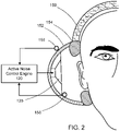
- FIG. 2 shows an example of an ANC system deployed in a headset 150.
- the headset 150 includes an ear-cup 152 on each side, which fits on or over the ear of a user.
- the ear-cup 152 may include a layer 154 of soft material (e.g., soft foam) for a comfortable fit over the ear of the user.
- the ANC system on the headset 150 includes an external microphone 156 disposed on the outside of the ear-cup to detect ambient noise.
- the external microphone 156 may serve as the reference sensor (e.g., the reference sensor 110 shown in the block diagram of FIG. 1 ) for the ANC system.
- the ANC system also includes an internal microphone 158 which may serve as the error sensor (e.g., the error sensor 115 in the bock diagram of FIG.
- the internal microphone 158 can be deployed proximate (e.g., within a few millimeters) to the user's ear canal and/or the secondary source 125.
- the secondary source 125 can be the acoustic transducer that radiates audio signals from an audio source device that the headset 150 is connected to.
- the external microphone 156, the internal microphone 158, and the secondary source 125 are connected to an active noise control engine 120 as shown in FIG. 2 . While FIG. 2 shows the ANC engine 120 as a block external to the headset 150, the ANC engine 120 may be deployed in a portion of the headset 150 (e.g., in the ear-cup 152).
- the ANC engine 120 may also be deployed at a location external to the headset 150 (e.g., in a source device to which the headset 150 is connected). While FIG. 2 shows an ANC system deployed in a headset, such an ANC system may also be deployed in other personal acoustic devices such as earphones or hearing aids. Unless otherwise stated, any description with respect to headsets is applicable to such devices.
- the acoustic path between the noise source and the error sensor 115 may be referred to as the primary path 130, and the acoustic path between the secondary source 125 and error sensor 115 may be referred to as the secondary path 135.
- the acoustic path between the external microphone 156 and the internal microphone may form a portion of the primary path, and the acoustic path between the secondary source 125 and the internal microphone 158 may form the secondary path.
- the primary path 130 and/or the secondary path 135 can include additional components such as components of the ANC system or the environment in which the ANC system is deployed.
- the secondary path can include one or more components of the ANC engine 120, secondary source 125, and/or the error sensor 115 (e.g., the internal microphone 158).
- the secondary path can include electronic components of the ANC engine 120 and/or the secondary source 125, such as one or more digital filters, amplifiers, digital to analog (D/A) converters, analog to digital (A/D) converters, and digital signal processors.
- the secondary path can also include an electro-acoustic response (e.g., frequency response and/or magnitude and phase response) associated with the secondary source 125, an acoustic path associated with the secondary source 125 and dynamics associated with the error sensor 115.
- an ANC system may use a model of the secondary path (e.g., an acoustic transfer function representing the secondary path) in generating an anti-noise signal. Therefore, any changes to the model of the secondary path may affect the performance of the ANC system.
- the secondary path of a headset 150 can change when the headset is moved from one user to another.
- the secondary path may also change if one or more portions of a headset or earphone is changed. For example, if the cushioning layer 154 is removed, or swapped with a different cushioning layer, the secondary path of the headset 150 may be altered.
- the secondary path can change with the removal or swapping of such ear-tip.
- the corresponding ANC system may be rendered unstable.
- the ANC system may add more noise due to the instability. For a headset or earphone, this may be manifested, for example, by a screeching sound that degrades user-experience.
- adverse effects due to a change in the secondary path may be mitigated by selecting a different model or transfer function for the secondary path from a set of preset models.
- preset models for different changes may be unavailable, particularly if the nature of variation is not known in advance.
- an ANC earphone is to be made compatible with ear-tips manufactured by third-parties, preset models of the resulting secondary paths may not be available during the production of the ANC earphone.
- the technology described herein allows for updating the model of the secondary path using an adaptive filter.
- one or more adaptive filters may be run in a system identification mode to update the model of the secondary path. In some cases, this may allow for accommodating a wide range of variations in the secondary path. Accommodating such a wide range may be challenging, or even impossible, for an ANC headset or earphone that uses a limited number of preset models for the secondary paths.
- FIGs. 3A and 3B are block diagrams showing implementation details of an example ANC system 300 in accordance with the technology described herein.
- FIG. 3 is a block diagram of an example feedforward adaptive ANC system
- FIG. 4 is a block diagram of an example adaptive filter that can be used for modeling the secondary path in the ANC system of FIG. 3 .
- the ANC system 300 includes an adaptive filter that adapts to an unknown environment 305 represented by P(z) in the z domain.
- frequency domain functions may be represented in terms of their z domain representations, with the corresponding time domain (or sample domain) representations being functions of n.
- the transfer function of the secondary path 315 is represented as S(z).
- the adaptive filter 310 (represented as W(z)) can be configured to track time variations of the environment 305.
- the adaptive filter 310 can be configured to reduce (e.g., to substantially minimize) the residual error signal e(n). Therefore, the adaptive filter 310 is configured such that the target output y(n) of the adaptive filter 310, as processed by the secondary path, is substantially equal to the primary noise d(n).
- the output, when processed by the secondary path, can be represented as y'(n).
- the primary noise d(n) in this example is the source signal x(n) as processed by the unknown environment 305. Comparing FIG. 3 with the example of the ANC system deployed in the headset 150 (as shown in FIG.
- the secondary path 315 can therefore include the secondary source 125 and/or the acoustic path between the secondary source 125 and the internal microphone 158.
- the residual error e(n) is substantially equal to zero for perfect cancellation, and non-zero for imperfect cancellation.
- the ANC system 300 includes an adaptive engine 320.
- the adaptive engine 320 can be configured to compute and update the filter coefficients of the adaptive filter 310, for example, in accordance with changes in the primary noise.
- the adaptive engine 320 generates updated coefficients for the adaptive filter 310 based on output of a filter 325 configured to model the secondary path 315 of the active noise control system 300.
- the filter 325 is referred to herein as a system identification filter, the coefficients of which may represent, at least approximately, a transfer function of the secondary path 315.
- the ANC system 300 can include a second adaptive filter 330 for updating the coefficients of the system identification filter 325 in accordance with variations in the secondary path 315.
- coefficients of the second adaptive filter 330 can be updated by the adaptive engine 320.
- a separate adaptive engine may be provided for updating the coefficients of the second adaptive filter 330.
- the filter coefficients of the adaptive filter 310 and/or the second adaptive filter 330 can be updated based on an adaptive process implemented using the adaptive engine 320.
- the adaptive engine 320 can be implemented using a processing device such as a DSP, microcontroller, or microprocessor, and can be configured to update the coefficients of the adaptive filter 310 and/or the second adaptive filter 330 based on one or more input signals.
- the adaptive engine 320 can be configured to update the adaptive filter coefficients in various ways.
- the adaptive engine 320 can be configured to implement a least mean square (LMS) process (or a normalized least mean square (NLMS) process) to update the filter coefficients.
- LMS least mean square
- NLMS normalized least mean square
- ⁇ represents a scalar quantity for step size, i.e., a variable controlling how much the coefficients are adjusted towards the destination in each iteration
- ⁇ n E e 2 n is the mean squared error
- the adaptive engine 320 can be configured to implement a filtered X-LMS (FxLMS) process that uses affine projection.
- FxLMS filtered X-LMS
- the adaptive engine 320 can be configured to use past data to determine a future coefficient.
- X ap is a matrix that represents historical data related to the coefficient, with the number of columns being equal to the number of historical samples, and the number of rows being equal to the number of adaptive coefficients.
- e ap is a vector that represents corresponding historical error data.
- X ap is a matrix with two rows and five columns
- e ap is a vector of five elements.
- the number of historical samples used by the adaptive engine 320 can be experimentally determined, or determined based on theoretical criteria. The processes described above can also be used for generating the coefficients of the second adaptive filter 330.
- the coefficients of the system identification filter 325 are updated using the coefficients of the second adaptive filter 330 to account for dynamic changes in the secondary path 315.
- the coefficients of the system identification filter 325 can be updated upon determination of an unstable condition in the ANC system 300.
- the coefficients of the system identification filter 325 may be updated intermittently, for example, at periodic intervals, possibly regardless of whether any unstable condition is detected.
- the second adaptive filter 330 can be updated independently to the updating of the system identification filter.
- the second adaptive filter 330 may be updated substantially continuously, and the system identification filter 325 may be updated using the coefficients of the second adaptive filter 330, for example, upon detection of an unstable condition in the ANC system 300.
- the system identification filter 325 can have multiple taps or coefficients. For example, a 128 tap filter can be used as the system identification filter to account for an entire frequency range over which potential unstable conditions may be manifested in the ANC system 300. However, in many practical applications, a given unstable condition in the ANC system 300 is manifested over a range of frequencies that is much smaller than the entire frequency range represented by all the taps of the system identification filter. For example, for an ANC system deployed in a headset or earphone, a particular unstable condition may be manifested as an audible sound over a small frequency range, which is a subset of the entire frequency range over which other unstable conditions in the headset or earphone may be manifested.
- adapting the full range filter e.g., all 128 taps in the present example
- adapting the full range (128 taps in the present example) may be inefficient and inaccurate.
- such inaccurate adaptation of the taps or coefficients may also lead to other unstable conditions in the system.
- the convergence of a high-order full range filter may also be slow, and therefore potentially unsuitable for adapting to fast changes.
- the above noted problems may be mitigated by implementing the second adaptive filter 330 as a set of multiple subband adaptive filters.
- Each of the multiple subband adaptive filters has a smaller number of coefficients, and represent a corresponding portion of the frequency range associated with potential unstable conditions in the active noise control system 300.
- a given unstable condition in the ANC system 300 triggers updates to the coefficients of only one or more subbands that are associated with the smaller frequency range of the given unstable condition.
- the subband filters corresponding to the substantially unaffected frequency bands do not try to adapt to the unstable condition, which in turn may lead to reduced chances of inaccurate adaptions across all the taps of the second adaptive filter 330.
- fast convergence of such filters may make the filters suitable for adapting to fast changes.
- FIG. 5 is a block diagram of an ANC system 500 according to one embodiment of the present invention, where an adaptive filter 530 includes a bank of subband filters 532a-532n (532, in general).
- the filter coefficients of the filters 532 are generated by the adaptive engine 520.
- the coefficients of the subband filters 532 are combined to generate updated coefficients for the system identification filter 325.
- Each of the subband filters 532 is configured to adapt to changes in a corresponding portion of the entire frequency range associated with potential unstable conditions in the active noise control system 500.
- frequency ranges associated with consecutive subband filters 532 e.g., subband filters 532a and 532b
- a given subband filter 532 is updated to account for an unstable condition in the corresponding frequency range.
- the error signal e(n) may be passed through a filter bank 525 of bandpass filters 527 to split the error signal into multiple components. This process may be referred to a polyphase decomposition of the error signal.
- the passband of the individual bandpass filters 527 in the filter bank 525 are made at least partially non-overlapping such that the error signal is split into components that correspond to different frequency bands.
- each component of the error signal is then provided to the adaptive engine 520 to generate coefficients for an adaptive filter associated with the corresponding portion of the frequency range.
- the input signal x(n) (which is generated by the secondary source of the ANC system) is also decomposed using a filter bank 525 of bandpass filters 527.
- the input signal is therefore also split into multiple components corresponding to different frequency ranges, and provided to the adaptive engine 520 to generate coefficients for an adaptive filter associated with the corresponding portion of the frequency range.
- the individual components of the error signal and the input signal are downsampled, for example, to reduce processing burden for the adaptive engine 520.
- the adaptive engine 520 can be configured to generate coefficients for individual subband adaptive filters 532 based on the corresponding components of the input signal x(n) and the error signal e(n).
- the adaptive engine 520 is configured to compute a correlation between the corresponding components the input signal x(n) and the error signal e(n), and update the coefficients of the corresponding adaptive filter based on determining that the correlation satisfies a threshold condition. For example, if the correlation value satisfies the threshold, the adaptive engine 520 may determine that the coherence between the input and output in that particular frequency band is high, and update the filter coefficients accordingly to reduce such coherence.
- the updates can be performed in the frequency domain, which are then converted to filter coefficient values for subband filters 532, for example via a transformation operation such as an inverse Fast Fourier Transform (IFFT).
- IFFT inverse Fast Fourier Transform
- the filter coefficient values of the different subband filters 532 are combined (e.g., via an overlap-add or overlap-save process) and provided to the system identification filter 325.
- the coefficients of the subband filters can be combined and copied as the filter coefficients for the system identification filter 325 upon detection of an unstable condition in the ANC system 500.
- FIG. 5 illustrates one particular example of filter structures that may be used for the technology described herein. Other structures that use subband filters may also be used. Additional examples of such filter structures are described in the publication: Merched et. al, "A New Delayless Subband Adaptive Filter Structure," IEEE Transactions on Signal Processing, Vol. 47, No. 6, June 1999 .
- tracking accuracy of the subband filters 532 may be improved by providing additional spectral information that is processed by the adaptive engine 520 to generate the corresponding filter coefficients. This may be useful, for example, when the corresponding component of the error signal occupies a relatively small portion of the frequency range associated with the subband filter. In such cases, accuracy and/or convergence of the corresponding adaptive subband filter may be improved by artificially supplying additional spectral content/information for the frequency range associated with the subband filter.
- such information can be provided by adding shaped white noise to the output of the secondary source of the ANC system upon detection an unstable condition. The shaping of the white noise may depend, for example, on the nature of manifestation of the unstable condition.
- such additional spectral content may serve to broaden the frequency range over which the system identification is performed by a subband filter. Spectral content may also be added in generating updated coefficients for a full-range adaptive filter that does not include subband filters.
- FIG. 6 shows a flowchart for an example process 600 for updating coefficients of a system identification filter to account for changes to the secondary path of an ANC system.
- an adaptive engine e.g., the ANC engine 120 or the adaptive engines 320 or 520, as described above.
- Operations of the process 600 include detecting an onset of an unstable condition in an ANC system (610). As an ANC system begins to go unstable, the signal at the error sensor (e.g., the internal microphone 158 in FIG. 2 ) may become dominated by the output of the secondary source of the ANC system.
- detecting the onset of the unstable condition includes computing a correlation between signals from a secondary source and an error sensor of the active noise control system, and detecting the onset of the unstable condition upon determining that the correlation satisfies a threshold condition.
- FIG. 7A illustrates plots associated with an ANC system attempting to cancel a background noise represented by the plot 705.
- FIG. 7A shows the results of 5 second simulation of a broadband, feed-forward FxLMS adaptive filter.
- the plot 710 represents the signal received by the error sensor
- the plot 715 represents a correlation between the output of the secondary sensor and the signal received by the error sensor.
- the correlation plot 715 exhibits a peak around 0.2s.
- the signal received by the error sensor became highly correlated with the output of the secondary source, which indicated the onset of an unstable condition in the system.
- the system identification filter was reprogrammed upon detection of the unstable condition.
- the process 600 also includes obtaining updated filter coefficients for a system-identification filter configured to represent a transfer function of a secondary path of the active noise control system (620). This is done responsive to detection of the onset of the unstable condition.
- the updated filter coefficients can be generated using a set of multiple subband adaptive filters, wherein filter coefficients of each subband adaptive filter in the set are configured to adapt to changes in a corresponding portion of a frequency range associated with potential unstable conditions in the active noise control system. This includes obtaining the filter coefficients of each subband adaptive filter in the set, and generating the updated filter coefficients for the system-identification filter as a combination of filter coefficients of multiple subband adaptive filters.
- the corresponding portions of the frequency range associated with two subband adaptive filters of the set are at least partially non-overlapping.
- the filter coefficients for each subband filter in the set are updated based on a signal-to-noise ratio (SNR) in the portion of the frequency range associated with the corresponding subband filter. For example, considering the output of the secondary source as the signal, a high SNR may signify a run-away condition and therefore a potentially unstable condition.
- the coefficients of a subband filter are updated only if the SNR in the corresponding frequency range exceeds a threshold value. The threshold value may be determined experimentally.
- Operations of the process 600 also include programming the system identification filter with the updated coefficients to affect operation of the active noise control system (630). Affecting the operation of the active noise control system can include reducing an effect of the unstable condition. This is illustrated via the plots shown in FIGs. 7A and 7B .
- the system identification filter upon detection of the unstable condition, was reprogrammed with coefficients obtained from the subband filters. This resulted in a reduction of the error (as indicated by the time variance of the plot 710), as well as a reduction in the correlation between the output of the secondary sensor and the signal received by the error sensor (as indicated by the time variance of the plot 715). Further, FIG.
- FIG. 7B illustrates the reduction in the power spectral density (PSD) of the error signal 720 in comparison to the PSD of the noise signal 725 upon reprogramming of the system identification filter.
- FIG. 7C shows how the transfer function of the secondary path is tracked by that of the system identification filter.
- the plot 730 illustrates the magnitude response of a reference secondary path
- the plot 735 illustrates the magnitude response of the system identification filter implemented in accordance with the technology described herein. As evident from FIG. 7C , the magnitude response of the system identification filter was found to closely track the magnitude response of the reference secondary path.
- the functionality described herein, or portions thereof, and its various modifications can be implemented, at least in part, via a computer program product, e.g., a computer program tangibly embodied in an information carrier, such as one or more non-transitory machine-readable media or storage device, for execution by, or to control the operation of, one or more data processing apparatus, e.g., a programmable processor, a computer, multiple computers, and/or programmable logic components.
- a computer program product e.g., a computer program tangibly embodied in an information carrier, such as one or more non-transitory machine-readable media or storage device, for execution by, or to control the operation of, one or more data processing apparatus, e.g., a programmable processor, a computer, multiple computers, and/or programmable logic components.
- a computer program can be written in any form of programming language, including compiled or interpreted languages, and it can be deployed in any form, including as a stand-alone program or as a module, component, subroutine, or other unit suitable for use in a computing environment.
- a computer program can be deployed to be executed on one computer or on multiple computers at one site or distributed across multiple sites and interconnected by a network.
- Actions associated with implementing all or part of the functions can be performed by one or more programmable processors executing one or more computer programs to perform the functions of the calibration process. All or part of the functions can be implemented as, special purpose logic circuitry, e.g., an FPGA and/or an ASIC (application-specific integrated circuit).
- special purpose logic circuitry e.g., an FPGA and/or an ASIC (application-specific integrated circuit).
- processors suitable for the execution of a computer program include, by way of example, both general and special purpose microprocessors, and any one or more processors of any kind of digital computer.
- a processor will receive instructions and data from a read-only memory or a random access memory or both.
- Components of a computer include a processor for executing instructions and one or more memory devices for storing instructions and data.
- the technology described herein may be used to generate a customized set of coefficients for individual users, thereby allowing for increased personalization of ANC headsets. Further, because an abnormal or distorted transfer function of the secondary path may be indicative of a damaged product (or a particular abnormal condition), the generated coefficients for the system identification filter may be used, for example, in hardware diagnostics, and/or to mitigate abnormal or undesirable conditions.
- Elements of different implementations described herein may be combined to form other embodiments as defined in the appended claims. Elements may be left out of the structures described herein without adversely affecting their operation. Furthermore, various separate elements may be combined into one or more individual elements to perform the functions described herein.
Landscapes
- Engineering & Computer Science (AREA)
- Physics & Mathematics (AREA)
- Acoustics & Sound (AREA)
- Multimedia (AREA)
- Chemical & Material Sciences (AREA)
- Combustion & Propulsion (AREA)
- Mechanical Engineering (AREA)
- General Engineering & Computer Science (AREA)
- Soundproofing, Sound Blocking, And Sound Damping (AREA)
- Headphones And Earphones (AREA)
- Filters That Use Time-Delay Elements (AREA)
Claims (15)
- Procédé mis en œuvre par ordinateur (600) comprenant :la fourniture d'un système de régulation active de bruit (500) comprenant :- un ou plusieurs dispositifs de traitement,- un filtre d'identification de système (325) ayant des coefficients configurés pour représenter une fonction de transfert d'un trajet secondaire du système de régulation active de bruit,- un filtre adaptatif (530) comprenant une banque de multiples filtres adaptatifs de sous-bande (532) dont chacun a un plus petit nombre de coefficients et correspond à une partie différente d'une bande de fréquences,- un moteur adaptatif (520) configuré pour générer des coefficients pour les filtres adaptatifs de sous-bande,le système de régulation active de bruit étant agencé pour recevoir un signal d'entrée (x(n)) à partir d'une source de bruit et pour délivrer un signal d'erreur (e(n)) qui est sensiblement égal à zéro dans le cas d'une annulation de bruit parfaite ;la détection (610), par les un ou plusieurs dispositifs de traitement, de l'apparition d'un état instable et d'une gamme de fréquences associée à l'état instable détecté ;en réponse à la détection de l'apparition de l'état instable,la génération (620), par les un ou plusieurs dispositifs de traitement, de coefficients de filtre mis à jour pour le filtre d'identification de système (325), etla programmation (630) du filtre d'identification de système avec les coefficients de filtre mis à jour pour avoir une incidence sur le fonctionnement du système de régulation active de bruit ;le procédé étant caractérisé en ce que :les coefficients de filtre mis à jour pour le filtre d'identification de système sont générés comme une combinaison de coefficients de filtre de chacun des multiples filtres adaptatifs de sous-bande dans un ensemble de filtres adaptatifs de sous-bande correspondant à la gamme de fréquences associée à l'état instable détecté ; eten réponse à la détection de l'apparition de l'état instable :le calcul, par le moteur adaptatif, d'une valeur de corrélation entre les composantes correspondantes du signal d'entrée et du signal d'erreur, etla mise à jour, par le moteur adaptatif, sur la base du fait de déterminer que la corrélation calculée est conforme à un état seuil, de coefficients pour des filtres adaptatifs de sous-bande dans une partie correspondante de la gamme de fréquences détectée.
- Procédé (600) selon la revendication 1, dans lequel, lorsqu'une valeur de corrélation entre les composantes correspondantes du signal d'entrée et du signal d'erreur est conforme à l'état seuil, les coefficients de filtre des filtres adaptatifs de sous-bande sont mis à jour de manière à réduire une cohérence entre le signal d'entrée et le signal d'erreur.
- Procédé (600) selon la revendication 1, comprenant en outre l'obtention des coefficients de filtre de chaque filtre adaptatif de sous-bande dans l'ensemble ; et dans lequel la génération des coefficients de filtre mis à jour pour le filtre d'identification de système comme une combinaison de coefficients de filtre de multiples filtres adaptatifs de sous-bande est réalisée via un procédé d'ajout à chevauchement ou de sauvegarde à chevauchement.
- Procédé (600) selon la revendication 1, dans lequel les parties correspondantes de la gamme de fréquences associées à deux filtres adaptatifs de sous-bande de l'ensemble sont au moins partiellement sans chevauchement.
- Procédé (600) selon la revendication 1, dans lequel des coefficients de filtre pour chaque filtre de sous-bande dans l'ensemble sont mis à jour sur la base d'un rapport signal sur bruit (SNR) dans la partie de la gamme de fréquences associée au filtre de sous-bande correspondant.
- Procédé (600) selon la revendication 1, dans lequel le trajet secondaire (135) comprend un trajet électroacoustique entre un transducteur acoustique (125) et un détecteur d'erreurs (115) associé au système de régulation active de bruit.
- Procédé (600) selon la revendication 1, dans lequel l'incidence sur le fonctionnement du système de régulation active de bruit comprend la réduction d'un effet de l'état instable.
- Système de régulation active de bruit (300 ; 500) agencé pour recevoir un signal d'entrée (x(n)) à partir d'une source de bruit et pour délivrer un signal d'erreur (e(n)) qui est sensiblement égal à zéro dans le cas d'une annulation de bruit parfaite, le système de régulation active de bruit comprenant :un filtre d'identification de système (325) ayant des coefficients configurés pour représenter une fonction de transfert d'un trajet secondaire du système de régulation active de bruit ;un filtre adaptatif (530) comprenant une banque de multiples filtres adaptatifs de sous-bande (532) dont chacun a un plus petit nombre de coefficients et correspond à une partie différente d'une bande de fréquences ; etun moteur de régulation active de bruit (520) incluant un ou plusieurs processeurs, configuré pour générer des coefficients pour les filtres adaptatifs de sous-bande et configuré pour :détecter (610) l'apparition d'un état instable dans le système de régulation active de bruit et une gamme de fréquences associée à l'état instable détecté ; eten réponse à la détection de l'apparition de l'état instable,générer (620) des coefficients de filtre mis à jour pour le filtre d'identification de système, etprogrammer (630) le filtre d'identification de système avec les coefficients de filtre mis à jour pour avoir une incidence sur le fonctionnement du système de régulation active de bruit,le système de régulation active de bruit étant caractérisé en ce que :
en réponse à la détection de l'apparition de l'état instable, le moteur de régulation active de bruit est en outre configuré pour :calculer une valeur de corrélation entre les composantes correspondantes du signal d'entrée et du signal d'erreur,mettre à jour, sur la base du fait de déterminer que la corrélation calculée est conforme à un état seuil, des coefficients pour des filtres adaptatifs de sous-bande dans une partie correspondante de la gamme de fréquences détectée, etgénérer les coefficients de filtre mis à jour pour le filtre d'identification de système comme une combinaison de coefficients de filtre de chacun des multiples filtres adaptatifs de sous-bande dans un ensemble de filtres adaptatifs de sous-bande correspondant à la gamme de fréquences associée à l'état instable détecté. - Système de régulation active de bruit (300 ; 500) selon la revendication 8, dans lequel, lorsqu'une valeur de corrélation entre les composantes correspondantes du signal d'entrée et du signal d'erreur est conforme à l'état seuil, les coefficients de filtre des filtres adaptatifs de sous-bande sont mis à jour de manière à réduire une cohérence entre le signal d'entrée et le signal d'erreur.
- Système de régulation active de bruit (300 ; 500) selon la revendication 8, dans lequel le moteur de régulation active de bruit est en outre configuré pour :obtenir les coefficients de filtre de chaque filtre adaptatif de sous-bande dans l'ensemble ; etgénérer les coefficients de filtre mis à jour pour le filtre d'identification de système comme une combinaison de coefficients de filtre de multiples filtres adaptatifs de sous-bande, via un procédé d'ajout à chevauchement ou de sauvegarde à chevauchement.
- Système de régulation active de bruit (300 ; 500) selon la revendication 8, dans lequel les parties correspondantes de la gamme de fréquences associées à deux filtres adaptatifs de sous-bande de l'ensemble sont au moins partiellement sans chevauchement.
- Système de régulation active de bruit (300 ; 500) selon la revendication 8, dans lequel des coefficients de filtre pour chaque filtre de sous-bande dans l'ensemble sont mis à jour sur la base d'un rapport signal sur bruit (SNR) dans la partie de la gamme de fréquences associée au filtre de sous-bande correspondant.
- Système de régulation active de bruit (300 ; 500) selon la revendication 8, dans lequel le système de régulation active de bruit est disposé dans un casque (150).
- Système de régulation active de bruit (300 ; 500) selon la revendication 8, dans lequel le trajet secondaire comprend un trajet électroacoustique entre un transducteur acoustique et un détecteur d'erreurs associé au système de régulation active de bruit.
- Système de régulation active de bruit (300 ; 500) selon la revendication 8, dans lequel l'incidence sur le fonctionnement du système de régulation active de bruit comprend la réduction d'un effet de l'état instable.
Applications Claiming Priority (2)
| Application Number | Priority Date | Filing Date | Title |
|---|---|---|---|
| US15/085,204 US9704471B1 (en) | 2016-03-30 | 2016-03-30 | Adaptive modeling of secondary path in an active noise control system |
| PCT/US2017/024547 WO2017172774A1 (fr) | 2016-03-30 | 2017-03-28 | Modélisation adaptative de trajet secondaire dans un système de régulation de bruit actif |
Publications (2)
| Publication Number | Publication Date |
|---|---|
| EP3437090A1 EP3437090A1 (fr) | 2019-02-06 |
| EP3437090B1 true EP3437090B1 (fr) | 2022-12-07 |
Family
ID=58530669
Family Applications (1)
| Application Number | Title | Priority Date | Filing Date |
|---|---|---|---|
| EP17716715.2A Active EP3437090B1 (fr) | 2016-03-30 | 2017-03-28 | Modélisation adaptative de trajet secondaire dans un système de régulation de bruit actif |
Country Status (5)
| Country | Link |
|---|---|
| US (2) | US9704471B1 (fr) |
| EP (1) | EP3437090B1 (fr) |
| JP (1) | JP6625765B2 (fr) |
| CN (1) | CN109074800A (fr) |
| WO (1) | WO2017172774A1 (fr) |
Families Citing this family (23)
| Publication number | Priority date | Publication date | Assignee | Title |
|---|---|---|---|---|
| US11445306B2 (en) * | 2016-08-26 | 2022-09-13 | Starkey Laboratories, Inc. | Method and apparatus for robust acoustic feedback cancellation |
| SE541331C2 (en) | 2017-11-30 | 2019-07-09 | Creo Dynamics Ab | Active noise control method and system |
| SE1850077A1 (en) | 2018-01-24 | 2019-07-25 | Creo Dynamics Ab | Active noise control method and system using variable actuator and sensor participation |
| CN108550371B (zh) * | 2018-03-30 | 2021-06-01 | 云知声智能科技股份有限公司 | 智能语音交互设备快速稳定的回声消除方法 |
| US10425068B1 (en) | 2018-06-14 | 2019-09-24 | Nxp B.V. | Self-testing of an analog mixed-signal circuit using pseudo-random noise |
| US10396974B1 (en) | 2018-07-20 | 2019-08-27 | Nxp B.V. | Self-testing of a phase-locked loop using a pseudo-random noise |
| CN109613821B (zh) * | 2018-11-23 | 2021-10-22 | 重庆邮电大学 | 一种基于ANC系统中FxLMS改进算法的FPGA硬件结构 |
| US10937418B1 (en) * | 2019-01-04 | 2021-03-02 | Amazon Technologies, Inc. | Echo cancellation by acoustic playback estimation |
| CN109994098B (zh) * | 2019-01-11 | 2021-02-02 | 同济大学 | 一种基于次级通路离线重构的计权噪声主动控制方法 |
| US10917074B2 (en) * | 2019-03-29 | 2021-02-09 | Bose Corporation | Subband adaptive filter for systems with partially acausal transfer functions |
| US10586524B1 (en) * | 2019-03-29 | 2020-03-10 | Bose Corporation | Systems and methods for detecting divergence in an adaptive system |
| CN112565959A (zh) * | 2019-09-26 | 2021-03-26 | 广东思派康电子科技有限公司 | 一种接口耳机降噪设计方法 |
| BR112022004181A2 (pt) * | 2019-09-30 | 2022-05-31 | Shenzhen Shokz Co Ltd | Sistemas e métodos para redução de ruído usando a técnica de redução de ruído de sub-banda |
| CN110718205B (zh) * | 2019-10-17 | 2023-02-14 | 南京南大电子智慧型服务机器人研究院有限公司 | 一种无次级路径有源噪声控制系统及实现方法 |
| JP2023506802A (ja) * | 2019-12-12 | 2023-02-20 | シェンツェン・ショックス・カンパニー・リミテッド | ノイズ制御システム及び方法 |
| CN110996209B (zh) * | 2019-12-13 | 2022-02-15 | 恒玄科技(上海)股份有限公司 | 主动降噪方法、系统以及耳机 |
| CN110933554B (zh) * | 2019-12-13 | 2022-02-15 | 恒玄科技(上海)股份有限公司 | 主动降噪方法、系统以及耳机 |
| CN113015050B (zh) * | 2019-12-20 | 2022-11-22 | 瑞昱半导体股份有限公司 | 具有抗噪机制的音频播放装置及方法 |
| CN113077778B (zh) * | 2020-01-03 | 2023-01-10 | 中车唐山机车车辆有限公司 | 动车组主动降噪系统 |
| CN113365176B (zh) * | 2020-03-03 | 2023-04-28 | 华为技术有限公司 | 一种实现主动噪声消除的方法、装置和电子设备 |
| CN112201220B (zh) * | 2020-10-07 | 2023-06-23 | 安庆师范大学 | 分布式三维空间降噪系统及其使用方法 |
| CN112017683B (zh) * | 2020-10-20 | 2021-01-05 | 南京南大电子智慧型服务机器人研究院有限公司 | 一种频域无次级路径有源噪声控制系统 |
| WO2023077252A1 (fr) * | 2021-11-02 | 2023-05-11 | 华为技术有限公司 | Système, procédé et dispositif de réduction de bruit actif à base de structure fxlms |
Family Cites Families (16)
| Publication number | Priority date | Publication date | Assignee | Title |
|---|---|---|---|---|
| JPH0895577A (ja) * | 1994-09-21 | 1996-04-12 | Fujitsu Ten Ltd | 騒音制御装置 |
| JP3159176B2 (ja) | 1998-06-11 | 2001-04-23 | 日本電気株式会社 | 帯域分割適応フィルタによる未知システム同定方法及び装置 |
| US20100284546A1 (en) * | 2005-08-18 | 2010-11-11 | Debrunner Victor | Active noise control algorithm that requires no secondary path identification based on the SPR property |
| AU2003261203A1 (en) * | 2002-07-19 | 2004-02-09 | The Penn State Research Foundation | A linear independent method for noninvasive online secondary path modeling |
| ATE402468T1 (de) * | 2004-03-17 | 2008-08-15 | Harman Becker Automotive Sys | Geräuschabstimmungsvorrichtung, verwendung derselben und geräuschabstimmungsverfahren |
| CA2481629A1 (fr) * | 2004-09-15 | 2006-03-15 | Dspfactory Ltd. | Methode et systeme de suppression active du bruit |
| JP4549243B2 (ja) * | 2005-07-05 | 2010-09-22 | アルパイン株式会社 | 車載オーディオ処理装置 |
| EP2133866B1 (fr) * | 2008-06-13 | 2016-02-17 | Harman Becker Automotive Systems GmbH | Système de contrôle de bruit adaptatif |
| EP2365630B1 (fr) * | 2010-03-02 | 2016-06-08 | Harman Becker Automotive Systems GmbH | Filtrage FIR adaptatif de sous-bande efficace |
| EP2444967A1 (fr) * | 2010-10-25 | 2012-04-25 | Fraunhofer-Gesellschaft zur Förderung der Angewandten Forschung e.V. | Suppression d'écho comprenant la modélisation des composants de la réverbération tardive |
| US8718291B2 (en) * | 2011-01-05 | 2014-05-06 | Cambridge Silicon Radio Limited | ANC for BT headphones |
| EP2530840B1 (fr) * | 2011-05-30 | 2014-09-03 | Harman Becker Automotive Systems GmbH | Filtrage FIR adaptatif de sous-bande efficace |
| US9324311B1 (en) * | 2013-03-15 | 2016-04-26 | Cirrus Logic, Inc. | Robust adaptive noise canceling (ANC) in a personal audio device |
| US9591403B2 (en) * | 2013-08-22 | 2017-03-07 | Bose Corporation | Instability detection and correction in sinusoidal active noise reduction systems |
| US9240819B1 (en) * | 2014-10-02 | 2016-01-19 | Bose Corporation | Self-tuning transfer function for adaptive filtering |
| US10121464B2 (en) * | 2014-12-08 | 2018-11-06 | Ford Global Technologies, Llc | Subband algorithm with threshold for robust broadband active noise control system |
-
2016
- 2016-03-30 US US15/085,204 patent/US9704471B1/en active Active
-
2017
- 2017-03-28 JP JP2018551189A patent/JP6625765B2/ja active Active
- 2017-03-28 EP EP17716715.2A patent/EP3437090B1/fr active Active
- 2017-03-28 WO PCT/US2017/024547 patent/WO2017172774A1/fr active Application Filing
- 2017-03-28 CN CN201780021672.2A patent/CN109074800A/zh active Pending
- 2017-06-07 US US15/616,332 patent/US10056065B2/en active Active
Also Published As
| Publication number | Publication date |
|---|---|
| US10056065B2 (en) | 2018-08-21 |
| WO2017172774A1 (fr) | 2017-10-05 |
| US20170287461A1 (en) | 2017-10-05 |
| US9704471B1 (en) | 2017-07-11 |
| JP2019511878A (ja) | 2019-04-25 |
| EP3437090A1 (fr) | 2019-02-06 |
| CN109074800A (zh) | 2018-12-21 |
| JP6625765B2 (ja) | 2019-12-25 |
Similar Documents
| Publication | Publication Date | Title |
|---|---|---|
| EP3437090B1 (fr) | Modélisation adaptative de trajet secondaire dans un système de régulation de bruit actif | |
| EP2996112B1 (fr) | Système adaptatif de contrôle de bruit avec une robustesse améliorée | |
| US10373600B2 (en) | Active noise control system | |
| EP3472830B1 (fr) | Atténuation d'états instables dans un système actif de lutte contre le bruit | |
| US8385559B2 (en) | Adaptive digital noise canceller | |
| KR20200129038A (ko) | 차량 내 노이즈 상쇄 적응 필터 다이버전스 제어 | |
| US11250832B2 (en) | Feedforward active noise control | |
| US20200204916A1 (en) | Extended bandwidth adaptive noise cancelling system and methods | |
| CN116438597A (zh) | 用于适应所估计的次级路径的系统和方法 | |
| EP3994681B1 (fr) | Commande automatique de bruit | |
| EP3994682B1 (fr) | Commande automatique de bruit | |
| JP7449186B2 (ja) | 車載システム | |
| US11100910B2 (en) | Noise amplification control in adaptive noise cancelling systems |
Legal Events
| Date | Code | Title | Description |
|---|---|---|---|
| STAA | Information on the status of an ep patent application or granted ep patent |
Free format text: STATUS: UNKNOWN |
|
| STAA | Information on the status of an ep patent application or granted ep patent |
Free format text: STATUS: THE INTERNATIONAL PUBLICATION HAS BEEN MADE |
|
| PUAI | Public reference made under article 153(3) epc to a published international application that has entered the european phase |
Free format text: ORIGINAL CODE: 0009012 |
|
| STAA | Information on the status of an ep patent application or granted ep patent |
Free format text: STATUS: REQUEST FOR EXAMINATION WAS MADE |
|
| 17P | Request for examination filed |
Effective date: 20181002 |
|
| AK | Designated contracting states |
Kind code of ref document: A1 Designated state(s): AL AT BE BG CH CY CZ DE DK EE ES FI FR GB GR HR HU IE IS IT LI LT LU LV MC MK MT NL NO PL PT RO RS SE SI SK SM TR |
|
| AX | Request for extension of the european patent |
Extension state: BA ME |
|
| DAV | Request for validation of the european patent (deleted) | ||
| DAX | Request for extension of the european patent (deleted) | ||
| STAA | Information on the status of an ep patent application or granted ep patent |
Free format text: STATUS: EXAMINATION IS IN PROGRESS |
|
| 17Q | First examination report despatched |
Effective date: 20200820 |
|
| STAA | Information on the status of an ep patent application or granted ep patent |
Free format text: STATUS: EXAMINATION IS IN PROGRESS |
|
| STAA | Information on the status of an ep patent application or granted ep patent |
Free format text: STATUS: EXAMINATION IS IN PROGRESS |
|
| GRAP | Despatch of communication of intention to grant a patent |
Free format text: ORIGINAL CODE: EPIDOSNIGR1 |
|
| STAA | Information on the status of an ep patent application or granted ep patent |
Free format text: STATUS: GRANT OF PATENT IS INTENDED |
|
| INTG | Intention to grant announced |
Effective date: 20220912 |
|
| GRAS | Grant fee paid |
Free format text: ORIGINAL CODE: EPIDOSNIGR3 |
|
| GRAA | (expected) grant |
Free format text: ORIGINAL CODE: 0009210 |
|
| STAA | Information on the status of an ep patent application or granted ep patent |
Free format text: STATUS: THE PATENT HAS BEEN GRANTED |
|
| AK | Designated contracting states |
Kind code of ref document: B1 Designated state(s): AL AT BE BG CH CY CZ DE DK EE ES FI FR GB GR HR HU IE IS IT LI LT LU LV MC MK MT NL NO PL PT RO RS SE SI SK SM TR |
|
| REG | Reference to a national code |
Ref country code: GB Ref legal event code: FG4D |
|
| REG | Reference to a national code |
Ref country code: CH Ref legal event code: EP Ref country code: AT Ref legal event code: REF Ref document number: 1536780 Country of ref document: AT Kind code of ref document: T Effective date: 20221215 |
|
| REG | Reference to a national code |
Ref country code: DE Ref legal event code: R096 Ref document number: 602017064350 Country of ref document: DE |
|
| REG | Reference to a national code |
Ref country code: IE Ref legal event code: FG4D |
|
| REG | Reference to a national code |
Ref country code: LT Ref legal event code: MG9D |
|
| REG | Reference to a national code |
Ref country code: NL Ref legal event code: MP Effective date: 20221207 |
|
| PG25 | Lapsed in a contracting state [announced via postgrant information from national office to epo] |
Ref country code: SE Free format text: LAPSE BECAUSE OF FAILURE TO SUBMIT A TRANSLATION OF THE DESCRIPTION OR TO PAY THE FEE WITHIN THE PRESCRIBED TIME-LIMIT Effective date: 20221207 Ref country code: NO Free format text: LAPSE BECAUSE OF FAILURE TO SUBMIT A TRANSLATION OF THE DESCRIPTION OR TO PAY THE FEE WITHIN THE PRESCRIBED TIME-LIMIT Effective date: 20230307 Ref country code: LT Free format text: LAPSE BECAUSE OF FAILURE TO SUBMIT A TRANSLATION OF THE DESCRIPTION OR TO PAY THE FEE WITHIN THE PRESCRIBED TIME-LIMIT Effective date: 20221207 Ref country code: FI Free format text: LAPSE BECAUSE OF FAILURE TO SUBMIT A TRANSLATION OF THE DESCRIPTION OR TO PAY THE FEE WITHIN THE PRESCRIBED TIME-LIMIT Effective date: 20221207 Ref country code: ES Free format text: LAPSE BECAUSE OF FAILURE TO SUBMIT A TRANSLATION OF THE DESCRIPTION OR TO PAY THE FEE WITHIN THE PRESCRIBED TIME-LIMIT Effective date: 20221207 |
|
| PGFP | Annual fee paid to national office [announced via postgrant information from national office to epo] |
Ref country code: FR Payment date: 20230222 Year of fee payment: 7 |
|
| REG | Reference to a national code |
Ref country code: AT Ref legal event code: MK05 Ref document number: 1536780 Country of ref document: AT Kind code of ref document: T Effective date: 20221207 |
|
| PG25 | Lapsed in a contracting state [announced via postgrant information from national office to epo] |
Ref country code: RS Free format text: LAPSE BECAUSE OF FAILURE TO SUBMIT A TRANSLATION OF THE DESCRIPTION OR TO PAY THE FEE WITHIN THE PRESCRIBED TIME-LIMIT Effective date: 20221207 Ref country code: PL Free format text: LAPSE BECAUSE OF FAILURE TO SUBMIT A TRANSLATION OF THE DESCRIPTION OR TO PAY THE FEE WITHIN THE PRESCRIBED TIME-LIMIT Effective date: 20221207 Ref country code: LV Free format text: LAPSE BECAUSE OF FAILURE TO SUBMIT A TRANSLATION OF THE DESCRIPTION OR TO PAY THE FEE WITHIN THE PRESCRIBED TIME-LIMIT Effective date: 20221207 Ref country code: HR Free format text: LAPSE BECAUSE OF FAILURE TO SUBMIT A TRANSLATION OF THE DESCRIPTION OR TO PAY THE FEE WITHIN THE PRESCRIBED TIME-LIMIT Effective date: 20221207 Ref country code: GR Free format text: LAPSE BECAUSE OF FAILURE TO SUBMIT A TRANSLATION OF THE DESCRIPTION OR TO PAY THE FEE WITHIN THE PRESCRIBED TIME-LIMIT Effective date: 20230308 |
|
| PG25 | Lapsed in a contracting state [announced via postgrant information from national office to epo] |
Ref country code: NL Free format text: LAPSE BECAUSE OF FAILURE TO SUBMIT A TRANSLATION OF THE DESCRIPTION OR TO PAY THE FEE WITHIN THE PRESCRIBED TIME-LIMIT Effective date: 20221207 |
|
| PG25 | Lapsed in a contracting state [announced via postgrant information from national office to epo] |
Ref country code: SM Free format text: LAPSE BECAUSE OF FAILURE TO SUBMIT A TRANSLATION OF THE DESCRIPTION OR TO PAY THE FEE WITHIN THE PRESCRIBED TIME-LIMIT Effective date: 20221207 Ref country code: RO Free format text: LAPSE BECAUSE OF FAILURE TO SUBMIT A TRANSLATION OF THE DESCRIPTION OR TO PAY THE FEE WITHIN THE PRESCRIBED TIME-LIMIT Effective date: 20221207 Ref country code: PT Free format text: LAPSE BECAUSE OF FAILURE TO SUBMIT A TRANSLATION OF THE DESCRIPTION OR TO PAY THE FEE WITHIN THE PRESCRIBED TIME-LIMIT Effective date: 20230410 Ref country code: EE Free format text: LAPSE BECAUSE OF FAILURE TO SUBMIT A TRANSLATION OF THE DESCRIPTION OR TO PAY THE FEE WITHIN THE PRESCRIBED TIME-LIMIT Effective date: 20221207 Ref country code: CZ Free format text: LAPSE BECAUSE OF FAILURE TO SUBMIT A TRANSLATION OF THE DESCRIPTION OR TO PAY THE FEE WITHIN THE PRESCRIBED TIME-LIMIT Effective date: 20221207 Ref country code: AT Free format text: LAPSE BECAUSE OF FAILURE TO SUBMIT A TRANSLATION OF THE DESCRIPTION OR TO PAY THE FEE WITHIN THE PRESCRIBED TIME-LIMIT Effective date: 20221207 |
|
| PG25 | Lapsed in a contracting state [announced via postgrant information from national office to epo] |
Ref country code: SK Free format text: LAPSE BECAUSE OF FAILURE TO SUBMIT A TRANSLATION OF THE DESCRIPTION OR TO PAY THE FEE WITHIN THE PRESCRIBED TIME-LIMIT Effective date: 20221207 Ref country code: IS Free format text: LAPSE BECAUSE OF FAILURE TO SUBMIT A TRANSLATION OF THE DESCRIPTION OR TO PAY THE FEE WITHIN THE PRESCRIBED TIME-LIMIT Effective date: 20230407 Ref country code: AL Free format text: LAPSE BECAUSE OF FAILURE TO SUBMIT A TRANSLATION OF THE DESCRIPTION OR TO PAY THE FEE WITHIN THE PRESCRIBED TIME-LIMIT Effective date: 20221207 |
|
| REG | Reference to a national code |
Ref country code: DE Ref legal event code: R097 Ref document number: 602017064350 Country of ref document: DE |
|
| PLBE | No opposition filed within time limit |
Free format text: ORIGINAL CODE: 0009261 |
|
| STAA | Information on the status of an ep patent application or granted ep patent |
Free format text: STATUS: NO OPPOSITION FILED WITHIN TIME LIMIT |
|
| PG25 | Lapsed in a contracting state [announced via postgrant information from national office to epo] |
Ref country code: MC Free format text: LAPSE BECAUSE OF FAILURE TO SUBMIT A TRANSLATION OF THE DESCRIPTION OR TO PAY THE FEE WITHIN THE PRESCRIBED TIME-LIMIT Effective date: 20221207 Ref country code: DK Free format text: LAPSE BECAUSE OF FAILURE TO SUBMIT A TRANSLATION OF THE DESCRIPTION OR TO PAY THE FEE WITHIN THE PRESCRIBED TIME-LIMIT Effective date: 20221207 |
|
| REG | Reference to a national code |
Ref country code: CH Ref legal event code: PL |
|
| 26N | No opposition filed |
Effective date: 20230908 |
|
| PG25 | Lapsed in a contracting state [announced via postgrant information from national office to epo] |
Ref country code: SI Free format text: LAPSE BECAUSE OF FAILURE TO SUBMIT A TRANSLATION OF THE DESCRIPTION OR TO PAY THE FEE WITHIN THE PRESCRIBED TIME-LIMIT Effective date: 20221207 |
|
| REG | Reference to a national code |
Ref country code: BE Ref legal event code: MM Effective date: 20230331 |
|
| PG25 | Lapsed in a contracting state [announced via postgrant information from national office to epo] |
Ref country code: LU Free format text: LAPSE BECAUSE OF NON-PAYMENT OF DUE FEES Effective date: 20230328 |
|
| REG | Reference to a national code |
Ref country code: IE Ref legal event code: MM4A |
|
| PG25 | Lapsed in a contracting state [announced via postgrant information from national office to epo] |
Ref country code: LI Free format text: LAPSE BECAUSE OF NON-PAYMENT OF DUE FEES Effective date: 20230331 Ref country code: IE Free format text: LAPSE BECAUSE OF NON-PAYMENT OF DUE FEES Effective date: 20230328 Ref country code: CH Free format text: LAPSE BECAUSE OF NON-PAYMENT OF DUE FEES Effective date: 20230331 |
|
| PG25 | Lapsed in a contracting state [announced via postgrant information from national office to epo] |
Ref country code: BE Free format text: LAPSE BECAUSE OF NON-PAYMENT OF DUE FEES Effective date: 20230331 |
|
| PGFP | Annual fee paid to national office [announced via postgrant information from national office to epo] |
Ref country code: DE Payment date: 20240220 Year of fee payment: 8 Ref country code: GB Payment date: 20240220 Year of fee payment: 8 |