EP3435195B1 - Systeme de came comportant au moins un module mobile de commande d'un dispositif actionnaire - Google Patents
Systeme de came comportant au moins un module mobile de commande d'un dispositif actionnaire Download PDFInfo
- Publication number
- EP3435195B1 EP3435195B1 EP17193453.2A EP17193453A EP3435195B1 EP 3435195 B1 EP3435195 B1 EP 3435195B1 EP 17193453 A EP17193453 A EP 17193453A EP 3435195 B1 EP3435195 B1 EP 3435195B1
- Authority
- EP
- European Patent Office
- Prior art keywords
- cam
- base
- screw
- rotation
- worm screw
- Prior art date
- Legal status (The legal status is an assumption and is not a legal conclusion. Google has not performed a legal analysis and makes no representation as to the accuracy of the status listed.)
- Active
Links
Images


Classifications
-
- H—ELECTRICITY
- H01—ELECTRIC ELEMENTS
- H01H—ELECTRIC SWITCHES; RELAYS; SELECTORS; EMERGENCY PROTECTIVE DEVICES
- H01H3/00—Mechanisms for operating contacts
- H01H3/32—Driving mechanisms, i.e. for transmitting driving force to the contacts
- H01H3/42—Driving mechanisms, i.e. for transmitting driving force to the contacts using cam or eccentric
-
- F—MECHANICAL ENGINEERING; LIGHTING; HEATING; WEAPONS; BLASTING
- F16—ENGINEERING ELEMENTS AND UNITS; GENERAL MEASURES FOR PRODUCING AND MAINTAINING EFFECTIVE FUNCTIONING OF MACHINES OR INSTALLATIONS; THERMAL INSULATION IN GENERAL
- F16H—GEARING
- F16H1/00—Toothed gearings for conveying rotary motion
- F16H1/02—Toothed gearings for conveying rotary motion without gears having orbital motion
- F16H1/04—Toothed gearings for conveying rotary motion without gears having orbital motion involving only two intermeshing members
- F16H1/12—Toothed gearings for conveying rotary motion without gears having orbital motion involving only two intermeshing members with non-parallel axes
- F16H1/16—Toothed gearings for conveying rotary motion without gears having orbital motion involving only two intermeshing members with non-parallel axes comprising worm and worm-wheel
- F16H1/166—Toothed gearings for conveying rotary motion without gears having orbital motion involving only two intermeshing members with non-parallel axes comprising worm and worm-wheel with members rotating around axes on the worm or worm-wheel
-
- F—MECHANICAL ENGINEERING; LIGHTING; HEATING; WEAPONS; BLASTING
- F16—ENGINEERING ELEMENTS AND UNITS; GENERAL MEASURES FOR PRODUCING AND MAINTAINING EFFECTIVE FUNCTIONING OF MACHINES OR INSTALLATIONS; THERMAL INSULATION IN GENERAL
- F16H—GEARING
- F16H1/00—Toothed gearings for conveying rotary motion
- F16H1/02—Toothed gearings for conveying rotary motion without gears having orbital motion
- F16H1/04—Toothed gearings for conveying rotary motion without gears having orbital motion involving only two intermeshing members
- F16H1/12—Toothed gearings for conveying rotary motion without gears having orbital motion involving only two intermeshing members with non-parallel axes
- F16H1/16—Toothed gearings for conveying rotary motion without gears having orbital motion involving only two intermeshing members with non-parallel axes comprising worm and worm-wheel
-
- G—PHYSICS
- G05—CONTROLLING; REGULATING
- G05G—CONTROL DEVICES OR SYSTEMS INSOFAR AS CHARACTERISED BY MECHANICAL FEATURES ONLY
- G05G5/00—Means for preventing, limiting or returning the movements of parts of a control mechanism, e.g. locking controlling member
- G05G5/02—Means preventing undesired movements of a controlling member which can be moved in two or more separate steps or ways, e.g. restricting to a stepwise movement or to a particular sequence of movements
-
- E—FIXED CONSTRUCTIONS
- E05—LOCKS; KEYS; WINDOW OR DOOR FITTINGS; SAFES
- E05B—LOCKS; ACCESSORIES THEREFOR; HANDCUFFS
- E05B37/00—Permutation or combination locks; Puzzle locks
- E05B37/02—Permutation or combination locks; Puzzle locks with tumbler discs or rings arranged on a single axis, each disc being adjustable independently of the others
-
- E—FIXED CONSTRUCTIONS
- E05—LOCKS; KEYS; WINDOW OR DOOR FITTINGS; SAFES
- E05B—LOCKS; ACCESSORIES THEREFOR; HANDCUFFS
- E05B49/00—Electric permutation locks; Circuits therefor ; Mechanical aspects of electronic locks; Mechanical keys therefor
- E05B49/002—Keys with mechanical characteristics, e.g. notches, perforations, opaque marks
- E05B49/004—Keys with mechanical characteristics, e.g. notches, perforations, opaque marks actuating mechanical switches
-
- E—FIXED CONSTRUCTIONS
- E05—LOCKS; KEYS; WINDOW OR DOOR FITTINGS; SAFES
- E05B—LOCKS; ACCESSORIES THEREFOR; HANDCUFFS
- E05B63/00—Locks or fastenings with special structural characteristics
-
- F—MECHANICAL ENGINEERING; LIGHTING; HEATING; WEAPONS; BLASTING
- F16—ENGINEERING ELEMENTS AND UNITS; GENERAL MEASURES FOR PRODUCING AND MAINTAINING EFFECTIVE FUNCTIONING OF MACHINES OR INSTALLATIONS; THERMAL INSULATION IN GENERAL
- F16H—GEARING
- F16H53/00—Cams or cam-followers, e.g. rollers for gearing mechanisms
- F16H53/02—Single-track cams for single-revolution cycles; Camshafts with such cams
- F16H53/04—Adjustable cams
Definitions
- the invention relates to a cam system comprising at least one mobile module for controlling an actuator device, in particular an electrical contact, the end position of which is adjustable by means of a gear device.
- US 3,128,638 A describes a control device including a timing cam for an electrical switch which allows precise adjustment of when the switch is actuated.
- the device includes a worm transmission and a cam locking system.
- the invention aims to overcome this drawback.
- the invention proposes a control cam system as described in claim 1, comprising in particular a base device secured in rotation to a rotary shaft and a cam mounted adjustable in angular position on the base and in what the adjustment device comprises a endless screw mounted on the base and which meshes with teeth associated with the cam so that a rotation of the screw causes a change in the angular position of the cam on the base.
- FIG. 1 shows, by way of non-exclusive example, a system of four adjustable cam modules 1 according to the invention, which are stacked on the same rotary drive shaft 3.
- Each module as shown in figure 2 comprises a base 5 secured in rotation to the shaft 3 and a cam disc 7 which is mounted on the base 5 adjustable in angular position by means of a gear device 9.
- Each cam disc is intended to control an electrical contact 10 of an external support structure 11.
- This gear device 9 essentially comprises a worm screw 13 fixedly mounted in the base 5 and extending perpendicular to the shaft 3 and which meshes with a toothed ring 15 concentric with the shaft 3 and integral in rotation with the cam disc 7.
- the teeth 16 of the crown 15 are slightly inclined relative to the direction of the axis of the shaft 3.
- the cam disc 7 comprises a cylindrical end piece 18 which projects perpendicularly from the surface of the disc and is intended to engage on a complementary cylindrical end piece 20 of the base 5.
- the toothed ring 15 is arranged coaxially on the end piece 18 of the cam disc 7 being integral in rotation with it, as shown in particular by the figures 2 And 3 .
- the base 5 is made in the form of an oval bowl comprising side walls 22 which extend perpendicularly from the bottom 23 as seen in the figure 2 .
- the disc In its mounted position on the base, the disc rests on the free upper edge of the side wall 22 of the base, more precisely on raised parts 24, 25 of this wall which are located at the opposite portions relative to the axis and the furthest from each other.
- the side wall is not rounded but has a profile, in the top view, in the shape of a U whose branches 28 are parallel.
- a cutout 30 is made in the shape of an arc of a circle.
- cutouts are intended to receive the endless screw 13 which extends, as indicated above, perpendicular to the drive shaft 3 of the base.
- the axis of this shaft coincides with the axis of the end pieces 18 and 20 respectively of the disc 7 and the base 5.
- the position of the screw is chosen so that it can mesh with the teeth 16 of the toothed ring 15 to that a rotation of the screw causes the rotation of the crown 15 and thus of the cam disc 7.
- the ends of the screw are, for this purpose, configured to allow rotation of the screw by a tool such as a screwdriver. At least one end of the screw is accessible from the outside for this purpose.
- the base is fixed on the shaft thanks to, for example, a non-circular opening 32, for example hexagonal, in the bottom wall 23 of the base.
- the screw comprises at each end, that is to say on either side of the threaded part, a part with a multi-section cross section, for example, hexagonal and the module comprises, associated at each of the two hexagonal portions 34 a spring 36 which is supported by one end on a stop element (not shown) of the base and acts by its other end on one of the six sides of the part with a hexagonal section of the screw.
- the screw is maintained in a desired angular position following adjustment by rotation of this screw, by the pressure exerted by the springs on the support panel.
- the sides on one side of the threaded part of the screw are angularly offset by 30° relative to the sides on the other side, which provides blocking and also indexing in 12 positions.
- the toothed ring 15 is integral in rotation with the axis 3 and the screw 13 is provided on the cam 7 which carries a contact control element 37.
- the figure 7 shows a module conforming to the figure 5 , but provided with another version of realization of the means for blocking the position of the cam after an adjustment.
- the screw 13 comprises, on either side of its threaded part, a series of impressions 39 which are made in the peripheral surface of the screw and angularly distributed thereon.
- the locking means comprise two helical springs 36, each mounted in a holding element 40 and associated with a series of impressions and provided at its end adjacent to the screw with a spherical element 41 intended to engage removably under the The effect of the spring in a cavity, following an adjustment of the position of the cam. If necessary, by shifting the imprints of the two series angularly, we can double the number of indexing positions.
Landscapes
- Engineering & Computer Science (AREA)
- General Engineering & Computer Science (AREA)
- Mechanical Engineering (AREA)
- Structural Engineering (AREA)
- Physics & Mathematics (AREA)
- General Physics & Mathematics (AREA)
- Automation & Control Theory (AREA)
- Transmission Devices (AREA)
- Gear Transmission (AREA)
- Chairs For Special Purposes, Such As Reclining Chairs (AREA)
Description
- L'invention concerne un système de came comportant au moins un module mobile de commande d'un dispositif actionneur, notamment d'un contact électrique, dont la position de fin de course est réglable au moyen d'un dispositif à engrenage.
- Des systèmes de ce type, qui sont connus présentent l'inconvénient majeur d'avoir une structure complexe et être d'une manipulation non aisée.
US 3 128 638 A décrit un dispositif de commande comprenant une came de synchronisation pour un interrupteur électrique qui permet un réglage précis du moment où l'interrupteur est actionné. Le dispositif comprend une transmission à vis sans fin et un système de blocage de la came. - L'invention a pour but de pallier cet inconvénient.
- Pour atteindre ce but, l'invention propose un système de came de commande tel que décrit dans la revendication 1, comprenant notamment un dispositif de base solidaire en rotation d'un arbre rotatif et une came montée réglable en position angulaire sur la base et en ce que le dispositif de réglage comprend une vis sans fin montée sur la base et qui engrène une denture associée à la came afin qu'une rotation de la vis provoque un changement de la position angulaire de la came sur la base.
- L'invention sera mieux comprise, et d'autres buts, caractéristiques, détails et avantages de celle-ci apparaîtront plus clairement dans la description explicative qui va suivre faite en référence aux dessins annexés donnés uniquement à titre d'exemple illustrant un mode de réalisation de l'invention et dans lesquels :
- la
figure 1 est une vue en perspective d'un système de came selon l'invention, qui comporte quatre modules de came réglable superposés; - la
figure 2 est une vue latérale d'un module de came réglable selon l'invention ; - la
figure 3 est une vue de dessous du module de lafigure 2 ; - les
figures 4A et 4B sont des vues en perspective respectivement, de la base de la came, et du dispositif d'engrenage du module de came réglable de lafigure 2 ; - la
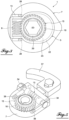
figure 5 est une vue d'un concept optimisé d'une partie d'un module de came réglable et verrouillable en position, ce concept n'appartient pas à l'invention ; - les
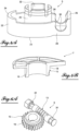
figures 6A et6B sont des vue en perspective des moyens de verrouillage de la came et des moyens d'indexation du concept de lafigure 5 ; et - la
figure 7 est une vue en perspective d'un mode de réalisation selon l'invention présentant une autre version du module de lafigure 5 . - La
figure 1 montre, à titre d'exemple non exclusif, un système de quatre modules de came 1 réglable selon l'invention, qui sont empilés sur un même arbre rotatif d'entrainement 3. - Chaque module tel que représenté à la
figure 2 comprend une base 5 solidaire en rotation de l'arbre 3 et un disque à came 7 qui est monté sur la base 5 réglable en position angulaire au moyen d'un dispositif à engrenage 9. Chaque disque à came est destiné à commander un contact électrique 10 d'une structure de support extérieure 11. Ce dispositif d'engrenage 9 comprend essentiellement une vis sans fin 13 montée fixe dans la base 5 et s'étendant perpendiculairement à l'arbre 3 et qui engrène une couronne dentée 15 concentrique à l'arbre 3 et solidaire en rotation du disque de came 7. Les dents 16 de la couronne 15 sont légèrement inclinées par rapport à la direction de l'axe de l'arbre 3. - En se reportant notamment aux
figures 4A et 4B , on voit que le disque à came 7 comprend un embout cylindrique 18 qui fait saillie perpendiculairement de la surface du disque et est destiné à s'engager sur un embout cylindrique complémentaire 20 de la base 5. La couronne dentée 15 est disposée coaxialement sur l'embout 18 du disque à came 7 en étant solidaire en rotation de celui-ci, comme le montre notamment lesfigures 2 et3 . - Ainsi la vis sans fin 13 est solidaire de la base 5. La came 7 est en mouvement par rapport à la base 5.
- La base 5 est réalisée sous forme d'une cuvette ovale comportant des parois latérales 22 qui s'étendent perpendiculairement à partir du fond 23 comme on le voit sur la
figure 2 . Dans sa position montée sur la base, le disque prend appui sur le bord supérieur libre de la paroi latérale 22 de la base, plus précisément sur des parties surélevées 24, 25 de cette paroi qui sont situées au niveau des portions opposées par rapport à l'axe et les plus éloignées l'une de l'autre. On constate qu'au niveau de la paroi surélevée 25, la paroi latérale n'est pas arrondie mais présente un profil, dans la vue de dessus, en forme d'un U dont les branches 28 sont parallèles. Dans chacune de ces portions de paroi est pratiquée une découpe 30 en forme d'un arc de cercle. Ces découpes sont destinées à recevoir la vis sans fin 13 qui s'étend, comme indiqué plus haut, perpendiculairement à l'arbre 3 d'entrainement de la base. L'axe de cet arbre est confondu avec l'axe des embouts 18 et 20 respectivement du disque 7 et de la base 5. La position de la vis est choisie de façon qu'elle puisse engrener les dents 16 de la couronne dentée 15 pour qu'une rotation de la vis provoque la rotation de la couronne 15 et ainsi du disque à came 7. Les extrémités de la vis sont, à cette fin, configurées pour permettre un entrainement en rotation de la vis par un outil tel qu'un tournevis. Au moins une extrémité de la vis est à cette fin accessible de l'extérieur. Il est encore à noter que la base est fixée sur l'arbre grâce à par exemple une ouverture non circulaire 32, par exemple hexagonale, dans la paroi de fond 23 de la base. - Grâce à l'inclinaison des filets de la vis et des dents de la couronne, lorsque la came est amenée par rotation de la vis dans une position prédéterminée souhaitée, cette position est assurée par un effet d'auto-blocage lorsque la came est soumise à une force de résistance, c'est-à-dire lorsque la came atteint le contact à actionner.
- Dans la version de mise en oeuvre d'un exemple de système de came de commande représentée aux
figures 5 ,6A et6B , la vis sans fin 13 est solidaire de la came 37, et par contre la couronne dentée 15 est fixe. Cet exemple n'appartient pas à l'objet de l'invention. - Le blocage de la position de la came, après un réglage, est assuré par des moyens de blocage spécifiques illustrés clairement sur la
figure 6B . A cette fin, la vis comporte au niveau de chaque extrémité, c'est-à-dire de part et d'autre de la partie filetée, une partie à section transversale multi-pans, par exemple, hexagonale et le module comporte, associé à chacune des deux portions hexagonales 34 un ressort 36 qui prend appui par une extrémité sur un élément de butée (non représenté) de la base et agit par son autre extrémité sur un des six pans de la partie à section hexagonale de la vis. Ainsi, la vis est maintenue dans une position angulaire souhaitée suite à un réglage par rotation de cette vis, par la pression qu'exercent les ressorts sur le pan d'appui. Sur la figure, les pans d'un côté de la partie filetée de la vis sont angulairement décalés de 30° par rapport aux pans de l'autre côté, ce qui procure un blocage et aussi un indexage en 12 positions. Il est à noter, comme mentionné plus haut, que sur lafigure 5 , la couronne dentée 15 est solidaire en rotation de l'axe 3 et la vis 13 est prévue sur la came 7 qui porte un élément de commande de contact 37. - Conformément à l'invention la
figure 7 montre un module conforme à lafigure 5 , mais pourvu d'une autre version de réalisation des moyens de blocage de la position de la came après un réglage. Dans cette version la vis 13 comprend, de part et d'autre de sa partie filetée une série d'empreintes 39 qui sont pratiquées dans la surface périphérique de la vis et angulairement réparties sur celle-ci. Comme sur lafigure 5 , les moyens de blocage comportent deux ressorts hélicoïdaux 36, chacun monté dans un élément de maintien 40 et associé à une série d'empreintes et pourvu à son extrémité adjacente à la vis d'un élément sphérique 41 destiné à s'engager amoviblement sous l'effet du ressort dans une empreinte, suite à un réglage de la position de la came. Le cas échéant, en décalant les empreintes des deux séries angulairement, on peut doubler le nombre des positions d'indexage. - Bien entendu, de multiples modifications peuvent être apportées au mode de réalisation de l'invention qui vient d'être décrit à titre d'exemple non limitatif, et toute modification utile peut être apportée à la présente invention sans sortir du cadre de celle-ci tel que défini par les revendications annexées. Ainsi les configurations de la base et de la came avec sa couronne peuvent être différentes, à condition de conserver, comme organe de réglage la vis sans fin ou un organe analogue, qui permet un actionnement facile de l'extérieur.
Claims (5)
- Système de came de commande comportant au moins un module de came mobile de commande d'un dispositif actionneur, notamment d'un contact électrique, dont la position de fin de course est réglable au moyen d'un dispositif à engrenage, le module comprenant une base (5) solidaire en rotation d'un arbre rotatif (3) et une came (7) montée réglable en position angulaire sur la base, et le dispositif à engrenage (9) comprenant une vis sans fin (13) montée sur la base (5) et engrenant une denture (16) associée à la came (7) afin qu'une rotation de la vis provoque un changement de la position angulaire de la came sur la base, cette came (7) étant verrouillable par des moyens de blocage de la vis sans fin dans sa position angulaire correspondante, caractérisé en ce que, pour assurer le blocage de la vis sans fin (13), celle-ci comprend des empreintes (39) pratiquées dans sa surface périphérique et angulairement décalées et en ce que la vis est bloquée par engagement d'un élément poussoir (36, 41) dans l'une de ces dites empreintes (39).
- Système selon la revendication précédente, caractérisé en ce que l'élément poussoir (36, 41) est formé par un ressort de compression (36) portant à son extrémité adjacente à la vis un élément sphérique (41) destiné à s'engager dans les empreintes (39).
- Système selon la revendication 1 ou 2, caractérisé en ce que la came est réalisée sous forme d'un disque présentant à sa périphérie une partie en forme de came.
- Système selon l'une des revendications 1 à 3, caractérisé en ce qu'il comprend une pluralité de modules de came de commande montée sur un arbre d'entrainement commun (3).
- Système selon l'une des revendications 1 à 4, caractérisé en ce que la vis sans fin (13) est disposée dans la base (5), perpendiculairement à l'arbre (3) d'entrainement en rotation de la base, et engrène une couronne dentée (15) qui est solidaire en rotation de la came (7).
Applications Claiming Priority (1)
| Application Number | Priority Date | Filing Date | Title |
|---|---|---|---|
| FR1757159A FR3069666B1 (fr) | 2017-07-27 | 2017-07-27 | Systeme de came comportant au moins un module mobile de commande d'un dispositif actionnaire |
Publications (2)
| Publication Number | Publication Date |
|---|---|
| EP3435195A1 EP3435195A1 (fr) | 2019-01-30 |
| EP3435195B1 true EP3435195B1 (fr) | 2024-05-29 |
Family
ID=60051327
Family Applications (1)
| Application Number | Title | Priority Date | Filing Date |
|---|---|---|---|
| EP17193453.2A Active EP3435195B1 (fr) | 2017-07-27 | 2017-09-27 | Systeme de came comportant au moins un module mobile de commande d'un dispositif actionnaire |
Country Status (8)
| Country | Link |
|---|---|
| US (1) | US20190035565A1 (fr) |
| EP (1) | EP3435195B1 (fr) |
| KR (1) | KR102148837B1 (fr) |
| CN (1) | CN109308092A (fr) |
| ES (1) | ES2983227T3 (fr) |
| FI (1) | FI3435195T3 (fr) |
| FR (1) | FR3069666B1 (fr) |
| RU (1) | RU2673355C1 (fr) |
Families Citing this family (1)
| Publication number | Priority date | Publication date | Assignee | Title |
|---|---|---|---|---|
| CN117775262A (zh) * | 2023-12-28 | 2024-03-29 | 中国航空工业集团公司西安飞机设计研究所 | 一种凸轮式电门机构 |
Citations (1)
| Publication number | Priority date | Publication date | Assignee | Title |
|---|---|---|---|---|
| US2903528A (en) * | 1958-03-31 | 1959-09-08 | Allen Bradley Co | Continuously adjustable limit switch |
Family Cites Families (23)
| Publication number | Priority date | Publication date | Assignee | Title |
|---|---|---|---|---|
| US284860A (en) * | 1883-09-11 | Jones | ||
| US1162693A (en) * | 1914-12-01 | 1915-11-30 | Gen Railway Signal Co | Adjustable cam. |
| US1421408A (en) * | 1919-03-27 | 1922-07-04 | Aeolian Co | Adjustable connection for actuating arms |
| GB322656A (en) * | 1928-12-19 | 1929-12-12 | Glyndwr Owen Ellis | Improvements in shaft couplings |
| US2226662A (en) * | 1939-08-05 | 1940-12-31 | Bendix Westinghouse Automotive | Brake mechanism |
| US2469570A (en) * | 1947-09-29 | 1949-05-10 | Crouse Hinds Co | Adjustable actuating member |
| US3080770A (en) * | 1961-04-18 | 1963-03-12 | Acton Lab Inc | Screw controlled relative positioning unit |
| US3128638A (en) * | 1961-08-15 | 1964-04-14 | Acton Lab Inc | Adjustable cam |
| US3338112A (en) * | 1966-02-23 | 1967-08-29 | U S Baird Corp | Adjustable cam |
| GB1459688A (en) * | 1974-06-07 | 1976-12-22 | Appliance Components Ltd | Adjustable cam assemblies |
| US4512167A (en) * | 1983-08-04 | 1985-04-23 | Sargent & Greenleaf, Inc. | Variable position quick mount combination lock |
| UA66824C2 (uk) * | 2000-06-22 | 2004-06-15 | Сергій Олександрович Фівейський | Електромеханічний замок |
| DE10311202A1 (de) * | 2003-03-14 | 2004-10-14 | Man B & W Diesel Ag | Lager für eine mit hoher Drehzahl umlaufende Welle |
| FI120109B (fi) * | 2006-05-02 | 2009-06-30 | Abloy Oy | Lukkorunko |
| TR200801927A2 (tr) * | 2008-03-24 | 2009-01-21 | Vemus Endüstri̇yel Elektroni̇k Sanayi̇ Ve Ti̇caret Li̇mi̇ted Şi̇rketi̇ | Mikro motorlu kilitleme dili sistemi. |
| US8302742B2 (en) * | 2008-11-18 | 2012-11-06 | Bendix Spicer Foundation Brake Llc | Self-setting automatic slack adjuster with increased durability |
| US8672101B2 (en) * | 2008-11-18 | 2014-03-18 | Bendix Spicer Foundation Brake Llc | Automatic slack adjuster with clutch release cam |
| KR101039897B1 (ko) * | 2009-08-13 | 2011-06-09 | 기아자동차주식회사 | 엔진의 연속 가변 밸브 리프트 장치 |
| CN102913077A (zh) * | 2012-09-24 | 2013-02-06 | 温州沃卡锘斯五金有限公司 | 带遥控器防盗警报自行车锁 |
| CN202833787U (zh) * | 2012-10-28 | 2013-03-27 | 陈槐 | 拉杆式制动调整臂 |
| KR101549429B1 (ko) * | 2014-04-23 | 2015-09-03 | 주식회사목림 | 가구용 높이 조절장치 |
| DE102014007287A1 (de) * | 2014-05-20 | 2015-11-26 | Thyssenkrupp Presta Teccenter Ag | Nockenwelle |
| US9957734B2 (en) * | 2014-07-03 | 2018-05-01 | Schlage Lock Company Llc | Mortise and multipoint latching assembly |
-
2017
- 2017-07-27 FR FR1757159A patent/FR3069666B1/fr active Active
- 2017-09-27 EP EP17193453.2A patent/EP3435195B1/fr active Active
- 2017-09-27 FI FIEP17193453.2T patent/FI3435195T3/fi active
- 2017-09-27 ES ES17193453T patent/ES2983227T3/es active Active
- 2017-09-27 US US15/716,611 patent/US20190035565A1/en not_active Abandoned
- 2017-10-04 RU RU2017134869A patent/RU2673355C1/ru active
- 2017-11-03 KR KR1020170146000A patent/KR102148837B1/ko active Active
- 2017-11-03 CN CN201711070309.8A patent/CN109308092A/zh active Pending
Patent Citations (1)
| Publication number | Priority date | Publication date | Assignee | Title |
|---|---|---|---|---|
| US2903528A (en) * | 1958-03-31 | 1959-09-08 | Allen Bradley Co | Continuously adjustable limit switch |
Also Published As
| Publication number | Publication date |
|---|---|
| US20190035565A1 (en) | 2019-01-31 |
| RU2673355C1 (ru) | 2018-11-26 |
| FR3069666B1 (fr) | 2021-11-05 |
| ES2983227T3 (es) | 2024-10-22 |
| KR20190013397A (ko) | 2019-02-11 |
| EP3435195A1 (fr) | 2019-01-30 |
| CN109308092A (zh) | 2019-02-05 |
| KR102148837B1 (ko) | 2020-08-27 |
| FI3435195T3 (fi) | 2024-08-21 |
| FR3069666A1 (fr) | 2019-02-01 |
Similar Documents
| Publication | Publication Date | Title |
|---|---|---|
| EP1046965B1 (fr) | Montre à remontage automatique | |
| FR2730441A1 (fr) | Dispositif de serrage destine a serrer un outil en forme de disque axialement a bloc | |
| CH703400A2 (fr) | Boîte de montre. | |
| EP3829015B1 (fr) | Appareillage a support d'appareillage basculant | |
| EP0402198A1 (fr) | Ensemble d'écrou à verrouillage | |
| EP3253615A1 (fr) | Ensemble d'articulation debrayable pour siege de vehicule automobile | |
| FR3069666A1 (fr) | Systeme de came comportant au moins un module mobile de commande d'un dispositif actionnaire | |
| EP0354081A1 (fr) | Dispositif de commande pour dérailleur de cycle | |
| EP3003776A1 (fr) | Ensemble d'articulation debrayable pour siege de vehicule automobile | |
| EP1441155B1 (fr) | Dispositif de commande de boîte de vitesses permettant un changement de rapport accéléré, et méthode de changement de rapport associé | |
| FR2944297A1 (fr) | Dispositif d'assemblage, ensemble de deux pieces assemblees par un tel dispositif et lame de machine de formation de la foule comprenant un tel ensemble | |
| EP2765463B1 (fr) | Mécanisme de transmission de mouvements axiaux et rotatifs entre deux axes décalés et pièce d'horlogerie comportant ce mécanisme | |
| FR2463698A1 (fr) | Dispositif de reglage de l'inclinaison relative de deux organes tels que les deux parties d'un siege de vehicule | |
| FR2531895A1 (fr) | Cle de serrage | |
| EP4053369B1 (fr) | Système de pivotement d'un support d appareillage et appareillage à encastrer comprenant un tel système de pivotement | |
| FR2774441A1 (fr) | Mecanisme d'embrayage a friction, notamment pour vehicule automobile, comportant un dispositif de rattrapage d'usure | |
| FR2587965A1 (fr) | Manivelle pour pedalier de bicyclette | |
| FR3006302A1 (fr) | Ouvre-boite manuel du type a arbre rotatif muni d'une molette et d'une poignee de manoeuvre | |
| FR2525724A1 (fr) | Mecanisme d'activation d'une vanne | |
| EP1369970B1 (fr) | Dispositif de fixation d'un coffret électrique sur une surface de support | |
| EP3063419A1 (fr) | Bague anti-desserrage d'un ecrou | |
| CH720109B1 (fr) | Mécanisme de sonnerie doté de plusieurs modes de fonctionnement | |
| EP3829014A1 (fr) | Appareillage avec un support d'appareillage basculant et un systeme de verrouillage debrayable au moyen d'une touche d'actionnement basculante | |
| FR2854221A1 (fr) | Dispositif de commande de boite de vitesse manuelle pilotee a grille de preselection et methode de changement de rapport associee | |
| FR3153760A1 (fr) | Outil d’installation d’un assemblage vis-écrou |
Legal Events
| Date | Code | Title | Description |
|---|---|---|---|
| PUAI | Public reference made under article 153(3) epc to a published international application that has entered the european phase |
Free format text: ORIGINAL CODE: 0009012 |
|
| STAA | Information on the status of an ep patent application or granted ep patent |
Free format text: STATUS: THE APPLICATION HAS BEEN PUBLISHED |
|
| AK | Designated contracting states |
Kind code of ref document: A1 Designated state(s): AL AT BE BG CH CY CZ DE DK EE ES FI FR GB GR HR HU IE IS IT LI LT LU LV MC MK MT NL NO PL PT RO RS SE SI SK SM TR |
|
| AX | Request for extension of the european patent |
Extension state: BA ME |
|
| STAA | Information on the status of an ep patent application or granted ep patent |
Free format text: STATUS: REQUEST FOR EXAMINATION WAS MADE |
|
| 17P | Request for examination filed |
Effective date: 20190730 |
|
| RBV | Designated contracting states (corrected) |
Designated state(s): AL AT BE BG CH CY CZ DE DK EE ES FI FR GB GR HR HU IE IS IT LI LT LU LV MC MK MT NL NO PL PT RO RS SE SI SK SM TR |
|
| STAA | Information on the status of an ep patent application or granted ep patent |
Free format text: STATUS: EXAMINATION IS IN PROGRESS |
|
| 17Q | First examination report despatched |
Effective date: 20210319 |
|
| GRAP | Despatch of communication of intention to grant a patent |
Free format text: ORIGINAL CODE: EPIDOSNIGR1 |
|
| STAA | Information on the status of an ep patent application or granted ep patent |
Free format text: STATUS: GRANT OF PATENT IS INTENDED |
|
| RIC1 | Information provided on ipc code assigned before grant |
Ipc: H01H 19/62 20060101ALN20231205BHEP Ipc: F16H 53/04 20060101ALI20231205BHEP Ipc: F16H 1/16 20060101ALI20231205BHEP Ipc: G05G 5/06 20060101AFI20231205BHEP |
|
| INTG | Intention to grant announced |
Effective date: 20231220 |
|
| RIN1 | Information on inventor provided before grant (corrected) |
Inventor name: GUILLAUME, ROMAIN Inventor name: DAJIC, IVAN |
|
| GRAS | Grant fee paid |
Free format text: ORIGINAL CODE: EPIDOSNIGR3 |
|
| GRAA | (expected) grant |
Free format text: ORIGINAL CODE: 0009210 |
|
| STAA | Information on the status of an ep patent application or granted ep patent |
Free format text: STATUS: THE PATENT HAS BEEN GRANTED |
|
| AK | Designated contracting states |
Kind code of ref document: B1 Designated state(s): AL AT BE BG CH CY CZ DE DK EE ES FI FR GB GR HR HU IE IS IT LI LT LU LV MC MK MT NL NO PL PT RO RS SE SI SK SM TR |
|
| REG | Reference to a national code |
Ref country code: CH Ref legal event code: EP |
|
| REG | Reference to a national code |
Ref country code: IE Ref legal event code: FG4D Free format text: LANGUAGE OF EP DOCUMENT: FRENCH |
|
| REG | Reference to a national code |
Ref country code: DE Ref legal event code: R096 Ref document number: 602017082247 Country of ref document: DE |
|
| P01 | Opt-out of the competence of the unified patent court (upc) registered |
Free format text: CASE NUMBER: APP_41623/2024 Effective date: 20240715 |
|
| REG | Reference to a national code |
Ref country code: FI Ref legal event code: FGE |
|
| REG | Reference to a national code |
Ref country code: LT Ref legal event code: MG9D |
|
| REG | Reference to a national code |
Ref country code: NL Ref legal event code: MP Effective date: 20240529 |
|
| PG25 | Lapsed in a contracting state [announced via postgrant information from national office to epo] |
Ref country code: IS Free format text: LAPSE BECAUSE OF FAILURE TO SUBMIT A TRANSLATION OF THE DESCRIPTION OR TO PAY THE FEE WITHIN THE PRESCRIBED TIME-LIMIT Effective date: 20240929 |
|
| PG25 | Lapsed in a contracting state [announced via postgrant information from national office to epo] |
Ref country code: BG Free format text: LAPSE BECAUSE OF FAILURE TO SUBMIT A TRANSLATION OF THE DESCRIPTION OR TO PAY THE FEE WITHIN THE PRESCRIBED TIME-LIMIT Effective date: 20240529 |
|
| PG25 | Lapsed in a contracting state [announced via postgrant information from national office to epo] |
Ref country code: HR Free format text: LAPSE BECAUSE OF FAILURE TO SUBMIT A TRANSLATION OF THE DESCRIPTION OR TO PAY THE FEE WITHIN THE PRESCRIBED TIME-LIMIT Effective date: 20240529 |
|
| PG25 | Lapsed in a contracting state [announced via postgrant information from national office to epo] |
Ref country code: GR Free format text: LAPSE BECAUSE OF FAILURE TO SUBMIT A TRANSLATION OF THE DESCRIPTION OR TO PAY THE FEE WITHIN THE PRESCRIBED TIME-LIMIT Effective date: 20240830 |
|
| REG | Reference to a national code |
Ref country code: AT Ref legal event code: MK05 Ref document number: 1691171 Country of ref document: AT Kind code of ref document: T Effective date: 20240529 |
|
| REG | Reference to a national code |
Ref country code: ES Ref legal event code: FG2A Ref document number: 2983227 Country of ref document: ES Kind code of ref document: T3 Effective date: 20241022 |
|
| PG25 | Lapsed in a contracting state [announced via postgrant information from national office to epo] |
Ref country code: AT Free format text: LAPSE BECAUSE OF FAILURE TO SUBMIT A TRANSLATION OF THE DESCRIPTION OR TO PAY THE FEE WITHIN THE PRESCRIBED TIME-LIMIT Effective date: 20240529 |
|
| PG25 | Lapsed in a contracting state [announced via postgrant information from national office to epo] |
Ref country code: PL Free format text: LAPSE BECAUSE OF FAILURE TO SUBMIT A TRANSLATION OF THE DESCRIPTION OR TO PAY THE FEE WITHIN THE PRESCRIBED TIME-LIMIT Effective date: 20240529 |
|
| PG25 | Lapsed in a contracting state [announced via postgrant information from national office to epo] |
Ref country code: LV Free format text: LAPSE BECAUSE OF FAILURE TO SUBMIT A TRANSLATION OF THE DESCRIPTION OR TO PAY THE FEE WITHIN THE PRESCRIBED TIME-LIMIT Effective date: 20240529 |
|
| PG25 | Lapsed in a contracting state [announced via postgrant information from national office to epo] |
Ref country code: PL Free format text: LAPSE BECAUSE OF FAILURE TO SUBMIT A TRANSLATION OF THE DESCRIPTION OR TO PAY THE FEE WITHIN THE PRESCRIBED TIME-LIMIT Effective date: 20240529 Ref country code: NO Free format text: LAPSE BECAUSE OF FAILURE TO SUBMIT A TRANSLATION OF THE DESCRIPTION OR TO PAY THE FEE WITHIN THE PRESCRIBED TIME-LIMIT Effective date: 20240829 Ref country code: LV Free format text: LAPSE BECAUSE OF FAILURE TO SUBMIT A TRANSLATION OF THE DESCRIPTION OR TO PAY THE FEE WITHIN THE PRESCRIBED TIME-LIMIT Effective date: 20240529 Ref country code: IS Free format text: LAPSE BECAUSE OF FAILURE TO SUBMIT A TRANSLATION OF THE DESCRIPTION OR TO PAY THE FEE WITHIN THE PRESCRIBED TIME-LIMIT Effective date: 20240929 Ref country code: HR Free format text: LAPSE BECAUSE OF FAILURE TO SUBMIT A TRANSLATION OF THE DESCRIPTION OR TO PAY THE FEE WITHIN THE PRESCRIBED TIME-LIMIT Effective date: 20240529 Ref country code: GR Free format text: LAPSE BECAUSE OF FAILURE TO SUBMIT A TRANSLATION OF THE DESCRIPTION OR TO PAY THE FEE WITHIN THE PRESCRIBED TIME-LIMIT Effective date: 20240830 Ref country code: BG Free format text: LAPSE BECAUSE OF FAILURE TO SUBMIT A TRANSLATION OF THE DESCRIPTION OR TO PAY THE FEE WITHIN THE PRESCRIBED TIME-LIMIT Effective date: 20240529 Ref country code: AT Free format text: LAPSE BECAUSE OF FAILURE TO SUBMIT A TRANSLATION OF THE DESCRIPTION OR TO PAY THE FEE WITHIN THE PRESCRIBED TIME-LIMIT Effective date: 20240529 Ref country code: RS Free format text: LAPSE BECAUSE OF FAILURE TO SUBMIT A TRANSLATION OF THE DESCRIPTION OR TO PAY THE FEE WITHIN THE PRESCRIBED TIME-LIMIT Effective date: 20240829 |
|
| P02 | Opt-out of the competence of the unified patent court (upc) changed |
Free format text: CASE NUMBER: APP_53085/2024 Effective date: 20240923 |
|
| PG25 | Lapsed in a contracting state [announced via postgrant information from national office to epo] |
Ref country code: NL Free format text: LAPSE BECAUSE OF FAILURE TO SUBMIT A TRANSLATION OF THE DESCRIPTION OR TO PAY THE FEE WITHIN THE PRESCRIBED TIME-LIMIT Effective date: 20240529 |
|
| PG25 | Lapsed in a contracting state [announced via postgrant information from national office to epo] |
Ref country code: NL Free format text: LAPSE BECAUSE OF FAILURE TO SUBMIT A TRANSLATION OF THE DESCRIPTION OR TO PAY THE FEE WITHIN THE PRESCRIBED TIME-LIMIT Effective date: 20240529 |
|
| PG25 | Lapsed in a contracting state [announced via postgrant information from national office to epo] |
Ref country code: DK Free format text: LAPSE BECAUSE OF FAILURE TO SUBMIT A TRANSLATION OF THE DESCRIPTION OR TO PAY THE FEE WITHIN THE PRESCRIBED TIME-LIMIT Effective date: 20240529 |
|
| PG25 | Lapsed in a contracting state [announced via postgrant information from national office to epo] |
Ref country code: EE Free format text: LAPSE BECAUSE OF FAILURE TO SUBMIT A TRANSLATION OF THE DESCRIPTION OR TO PAY THE FEE WITHIN THE PRESCRIBED TIME-LIMIT Effective date: 20240529 |
|
| PG25 | Lapsed in a contracting state [announced via postgrant information from national office to epo] |
Ref country code: CZ Free format text: LAPSE BECAUSE OF FAILURE TO SUBMIT A TRANSLATION OF THE DESCRIPTION OR TO PAY THE FEE WITHIN THE PRESCRIBED TIME-LIMIT Effective date: 20240529 |
|
| PG25 | Lapsed in a contracting state [announced via postgrant information from national office to epo] |
Ref country code: SK Free format text: LAPSE BECAUSE OF FAILURE TO SUBMIT A TRANSLATION OF THE DESCRIPTION OR TO PAY THE FEE WITHIN THE PRESCRIBED TIME-LIMIT Effective date: 20240529 Ref country code: RO Free format text: LAPSE BECAUSE OF FAILURE TO SUBMIT A TRANSLATION OF THE DESCRIPTION OR TO PAY THE FEE WITHIN THE PRESCRIBED TIME-LIMIT Effective date: 20240529 |
|
| PG25 | Lapsed in a contracting state [announced via postgrant information from national office to epo] |
Ref country code: SM Free format text: LAPSE BECAUSE OF FAILURE TO SUBMIT A TRANSLATION OF THE DESCRIPTION OR TO PAY THE FEE WITHIN THE PRESCRIBED TIME-LIMIT Effective date: 20240529 |
|
| PG25 | Lapsed in a contracting state [announced via postgrant information from national office to epo] |
Ref country code: SM Free format text: LAPSE BECAUSE OF FAILURE TO SUBMIT A TRANSLATION OF THE DESCRIPTION OR TO PAY THE FEE WITHIN THE PRESCRIBED TIME-LIMIT Effective date: 20240529 Ref country code: SK Free format text: LAPSE BECAUSE OF FAILURE TO SUBMIT A TRANSLATION OF THE DESCRIPTION OR TO PAY THE FEE WITHIN THE PRESCRIBED TIME-LIMIT Effective date: 20240529 Ref country code: RO Free format text: LAPSE BECAUSE OF FAILURE TO SUBMIT A TRANSLATION OF THE DESCRIPTION OR TO PAY THE FEE WITHIN THE PRESCRIBED TIME-LIMIT Effective date: 20240529 Ref country code: EE Free format text: LAPSE BECAUSE OF FAILURE TO SUBMIT A TRANSLATION OF THE DESCRIPTION OR TO PAY THE FEE WITHIN THE PRESCRIBED TIME-LIMIT Effective date: 20240529 Ref country code: DK Free format text: LAPSE BECAUSE OF FAILURE TO SUBMIT A TRANSLATION OF THE DESCRIPTION OR TO PAY THE FEE WITHIN THE PRESCRIBED TIME-LIMIT Effective date: 20240529 Ref country code: CZ Free format text: LAPSE BECAUSE OF FAILURE TO SUBMIT A TRANSLATION OF THE DESCRIPTION OR TO PAY THE FEE WITHIN THE PRESCRIBED TIME-LIMIT Effective date: 20240529 |
|
| REG | Reference to a national code |
Ref country code: DE Ref legal event code: R097 Ref document number: 602017082247 Country of ref document: DE |
|
| PLBE | No opposition filed within time limit |
Free format text: ORIGINAL CODE: 0009261 |
|
| STAA | Information on the status of an ep patent application or granted ep patent |
Free format text: STATUS: NO OPPOSITION FILED WITHIN TIME LIMIT |
|
| PG25 | Lapsed in a contracting state [announced via postgrant information from national office to epo] |
Ref country code: SI Free format text: LAPSE BECAUSE OF FAILURE TO SUBMIT A TRANSLATION OF THE DESCRIPTION OR TO PAY THE FEE WITHIN THE PRESCRIBED TIME-LIMIT Effective date: 20240529 Ref country code: MC Free format text: LAPSE BECAUSE OF FAILURE TO SUBMIT A TRANSLATION OF THE DESCRIPTION OR TO PAY THE FEE WITHIN THE PRESCRIBED TIME-LIMIT Effective date: 20240529 |
|
| REG | Reference to a national code |
Ref country code: CH Ref legal event code: PL |
|
| 26N | No opposition filed |
Effective date: 20250303 |
|
| PG25 | Lapsed in a contracting state [announced via postgrant information from national office to epo] |
Ref country code: LU Free format text: LAPSE BECAUSE OF NON-PAYMENT OF DUE FEES Effective date: 20240927 |
|
| PG25 | Lapsed in a contracting state [announced via postgrant information from national office to epo] |
Ref country code: CH Free format text: LAPSE BECAUSE OF NON-PAYMENT OF DUE FEES Effective date: 20240930 |
|
| PG25 | Lapsed in a contracting state [announced via postgrant information from national office to epo] |
Ref country code: IE Free format text: LAPSE BECAUSE OF NON-PAYMENT OF DUE FEES Effective date: 20240927 |
|
| PG25 | Lapsed in a contracting state [announced via postgrant information from national office to epo] |
Ref country code: SE Free format text: LAPSE BECAUSE OF FAILURE TO SUBMIT A TRANSLATION OF THE DESCRIPTION OR TO PAY THE FEE WITHIN THE PRESCRIBED TIME-LIMIT Effective date: 20240529 |
|
| PGFP | Annual fee paid to national office [announced via postgrant information from national office to epo] |
Ref country code: FI Payment date: 20250930 Year of fee payment: 9 |
|
| PGFP | Annual fee paid to national office [announced via postgrant information from national office to epo] |
Ref country code: IT Payment date: 20250929 Year of fee payment: 9 |
|
| PGFP | Annual fee paid to national office [announced via postgrant information from national office to epo] |
Ref country code: BE Payment date: 20250925 Year of fee payment: 9 Ref country code: GB Payment date: 20250927 Year of fee payment: 9 |
|
| PGFP | Annual fee paid to national office [announced via postgrant information from national office to epo] |
Ref country code: FR Payment date: 20250908 Year of fee payment: 9 |
|
| PG25 | Lapsed in a contracting state [announced via postgrant information from national office to epo] |
Ref country code: PT Free format text: LAPSE BECAUSE OF NON-PAYMENT OF DUE FEES Effective date: 20240529 |
|
| PGFP | Annual fee paid to national office [announced via postgrant information from national office to epo] |
Ref country code: DE Payment date: 20251002 Year of fee payment: 9 |
|
| PG25 | Lapsed in a contracting state [announced via postgrant information from national office to epo] |
Ref country code: CY Free format text: LAPSE BECAUSE OF FAILURE TO SUBMIT A TRANSLATION OF THE DESCRIPTION OR TO PAY THE FEE WITHIN THE PRESCRIBED TIME-LIMIT; INVALID AB INITIO Effective date: 20170927 |
|
| PGFP | Annual fee paid to national office [announced via postgrant information from national office to epo] |
Ref country code: ES Payment date: 20251001 Year of fee payment: 9 |
|
| PG25 | Lapsed in a contracting state [announced via postgrant information from national office to epo] |
Ref country code: HU Free format text: LAPSE BECAUSE OF FAILURE TO SUBMIT A TRANSLATION OF THE DESCRIPTION OR TO PAY THE FEE WITHIN THE PRESCRIBED TIME-LIMIT; INVALID AB INITIO Effective date: 20170927 |
|
| PG25 | Lapsed in a contracting state [announced via postgrant information from national office to epo] |
Ref country code: TR Free format text: LAPSE BECAUSE OF FAILURE TO SUBMIT A TRANSLATION OF THE DESCRIPTION OR TO PAY THE FEE WITHIN THE PRESCRIBED TIME-LIMIT Effective date: 20240529 |
|
| PG25 | Lapsed in a contracting state [announced via postgrant information from national office to epo] |
Ref country code: LT Free format text: LAPSE BECAUSE OF FAILURE TO SUBMIT A TRANSLATION OF THE DESCRIPTION OR TO PAY THE FEE WITHIN THE PRESCRIBED TIME-LIMIT Effective date: 20240529 |